CN108600590B - Terminal - Google Patents
TerminalDownload PDFInfo
- Publication number
- CN108600590B CN108600590BCN201810551033.3ACN201810551033ACN108600590BCN 108600590 BCN108600590 BCN 108600590BCN 201810551033 ACN201810551033 ACN 201810551033ACN 108600590 BCN108600590 BCN 108600590B
- Authority
- CN
- China
- Prior art keywords
- assembly
- valve
- camera
- terminal
- camera assembly
- Prior art date
- Legal status (The legal status is an assumption and is not a legal conclusion. Google has not performed a legal analysis and makes no representation as to the accuracy of the status listed.)
- Active
Links
Images


Classifications
- H—ELECTRICITY
- H04—ELECTRIC COMMUNICATION TECHNIQUE
- H04M—TELEPHONIC COMMUNICATION
- H04M1/00—Substation equipment, e.g. for use by subscribers
- H04M1/02—Constructional features of telephone sets
- H04M1/0202—Portable telephone sets, e.g. cordless phones, mobile phones or bar type handsets
- H04M1/026—Details of the structure or mounting of specific components
- H04M1/0264—Details of the structure or mounting of specific components for a camera module assembly
- H—ELECTRICITY
- H04—ELECTRIC COMMUNICATION TECHNIQUE
- H04N—PICTORIAL COMMUNICATION, e.g. TELEVISION
- H04N23/00—Cameras or camera modules comprising electronic image sensors; Control thereof
- H04N23/50—Constructional details
- H04N23/51—Housings
- G—PHYSICS
- G06—COMPUTING OR CALCULATING; COUNTING
- G06F—ELECTRIC DIGITAL DATA PROCESSING
- G06F21/00—Security arrangements for protecting computers, components thereof, programs or data against unauthorised activity
- G06F21/70—Protecting specific internal or peripheral components, in which the protection of a component leads to protection of the entire computer
- G06F21/82—Protecting input, output or interconnection devices
- G06F21/83—Protecting input, output or interconnection devices input devices, e.g. keyboards, mice or controllers thereof
- H—ELECTRICITY
- H04—ELECTRIC COMMUNICATION TECHNIQUE
- H04M—TELEPHONIC COMMUNICATION
- H04M1/00—Substation equipment, e.g. for use by subscribers
- H04M1/02—Constructional features of telephone sets
- H04M1/0202—Portable telephone sets, e.g. cordless phones, mobile phones or bar type handsets
- H04M1/026—Details of the structure or mounting of specific components
- H04M1/0266—Details of the structure or mounting of specific components for a display module assembly
- H—ELECTRICITY
- H04—ELECTRIC COMMUNICATION TECHNIQUE
- H04N—PICTORIAL COMMUNICATION, e.g. TELEVISION
- H04N23/00—Cameras or camera modules comprising electronic image sensors; Control thereof
- H04N23/50—Constructional details
- H—ELECTRICITY
- H04—ELECTRIC COMMUNICATION TECHNIQUE
- H04N—PICTORIAL COMMUNICATION, e.g. TELEVISION
- H04N23/00—Cameras or camera modules comprising electronic image sensors; Control thereof
- H04N23/57—Mechanical or electrical details of cameras or camera modules specially adapted for being embedded in other devices
- H—ELECTRICITY
- H04—ELECTRIC COMMUNICATION TECHNIQUE
- H04N—PICTORIAL COMMUNICATION, e.g. TELEVISION
- H04N23/00—Cameras or camera modules comprising electronic image sensors; Control thereof
- H04N23/60—Control of cameras or camera modules
- H—ELECTRICITY
- H04—ELECTRIC COMMUNICATION TECHNIQUE
- H04N—PICTORIAL COMMUNICATION, e.g. TELEVISION
- H04N23/00—Cameras or camera modules comprising electronic image sensors; Control thereof
- H04N23/60—Control of cameras or camera modules
- H04N23/61—Control of cameras or camera modules based on recognised objects
- H04N23/611—Control of cameras or camera modules based on recognised objects where the recognised objects include parts of the human body
- H—ELECTRICITY
- H04—ELECTRIC COMMUNICATION TECHNIQUE
- H04N—PICTORIAL COMMUNICATION, e.g. TELEVISION
- H04N23/00—Cameras or camera modules comprising electronic image sensors; Control thereof
- H04N23/60—Control of cameras or camera modules
- H04N23/62—Control of parameters via user interfaces
- H—ELECTRICITY
- H04—ELECTRIC COMMUNICATION TECHNIQUE
- H04N—PICTORIAL COMMUNICATION, e.g. TELEVISION
- H04N23/00—Cameras or camera modules comprising electronic image sensors; Control thereof
- H04N23/60—Control of cameras or camera modules
- H04N23/63—Control of cameras or camera modules by using electronic viewfinders
- H—ELECTRICITY
- H04—ELECTRIC COMMUNICATION TECHNIQUE
- H04M—TELEPHONIC COMMUNICATION
- H04M1/00—Substation equipment, e.g. for use by subscribers
- H04M1/66—Substation equipment, e.g. for use by subscribers with means for preventing unauthorised or fraudulent calling
- H04M1/667—Preventing unauthorised calls from a telephone set
- H04M1/67—Preventing unauthorised calls from a telephone set by electronic means
Landscapes
- Engineering & Computer Science (AREA)
- Signal Processing (AREA)
- Multimedia (AREA)
- Human Computer Interaction (AREA)
- Computer Hardware Design (AREA)
- Theoretical Computer Science (AREA)
- Computer Security & Cryptography (AREA)
- Software Systems (AREA)
- Physics & Mathematics (AREA)
- General Engineering & Computer Science (AREA)
- General Physics & Mathematics (AREA)
- Studio Devices (AREA)
Abstract
Translated fromChinese
Description
Translated fromChinese技术领域technical field
本发明涉及终端技术领域,特别是涉及一种终端。The present invention relates to the technical field of terminals, and in particular, to a terminal.
背景技术Background technique
随着科技水平的提高,电子产品配置的功能器件越来越多,从而可以满足用户各种各样的使用需求,例如手机、平板电脑等终端通常配置有摄像头,从而能够满足用户的拍摄需求。With the improvement of technology level, electronic products are equipped with more and more functional devices, which can meet the various needs of users. For example, terminals such as mobile phones and tablet computers are usually equipped with cameras, so as to meet the shooting needs of users.
目前,摄像头通常安装在终端机体的背面或屏幕上方,并外露于终端机体,用户可以通过相机应用等控制软件启动摄像头,并进行拍摄。At present, the camera is usually installed on the back of the terminal body or on the top of the screen, and is exposed on the terminal body. The user can activate the camera through control software such as a camera application and take pictures.
然而,由于摄像头暴露在终端机体之外,并由软件控制开启,而终端与其他电子设备进行交互时会存在一定的软件中毒风险,因此,在控制软件中毒时摄像头极易被控制开启,从而被不法分子利用,进行非法拍摄,进而暴露用户隐私。However, since the camera is exposed outside the terminal body and is controlled by software, and the terminal interacts with other electronic devices, there is a certain risk of software poisoning. Therefore, the camera is easily controlled to be turned on when controlling software poisoning Criminals use it to illegally shoot, thereby exposing user privacy.
发明内容SUMMARY OF THE INVENTION
本发明提供一种终端,以解决现有的摄像头外露于终端机体,并由软件控制开启,从而在控制软件中毒时摄像头极易被控制开启而用于偷拍的问题。The present invention provides a terminal to solve the problem that the existing camera is exposed on the terminal body and is controlled by software to be turned on, so that the camera can be easily controlled to be turned on for candid photography when the control software is poisoned.
为了解决上述问题,本发明公开了一种终端,包括容纳腔、摄像头控制装置;In order to solve the above-mentioned problems, the present invention discloses a terminal, comprising an accommodating cavity and a camera control device;
所述摄像头控制装置包括摄像头组件、开关阀组件、伸缩方向相互垂直的第一弹性组件和第二弹性组件;The camera control device includes a camera assembly, an on-off valve assembly, a first elastic assembly and a second elastic assembly whose expansion and contraction directions are perpendicular to each other;
所述容纳腔设置于所述终端内,所述容纳腔的开口位于所述终端的侧壁,所述摄像头控制装置设置于所述容纳腔内,所述摄像头组件配置为通过所述开口伸出或缩入所述终端,所述摄像头组件与所述终端电连接;The accommodating cavity is disposed in the terminal, the opening of the accommodating cavity is located on the side wall of the terminal, the camera control device is disposed in the accommodating cavity, and the camera assembly is configured to protrude through the opening or retracted into the terminal, the camera assembly is electrically connected to the terminal;
所述开关阀组件设置于所述容纳腔的侧壁,包括至少一个阀体和至少一个阀芯,所述至少一个阀芯可伸出或缩回所述至少一个阀体;The on-off valve assembly is disposed on the side wall of the accommodating cavity, and includes at least one valve body and at least one valve core, and the at least one valve core can extend or retract the at least one valve body;
所述第一弹性组件位于所述容纳腔的底部和所述摄像头组件之间,并与所述摄像头组件连接,所述第一弹性组件配置为在被释放沿所述摄像头组件的收缩方向的压力时,驱动所述摄像头组件伸出所述终端;The first elastic component is located between the bottom of the accommodating cavity and the camera head assembly, and is connected with the camera head assembly, the first elastic component is configured to be released from the pressure along the retraction direction of the camera head assembly when the camera assembly is driven to extend out of the terminal;
所述第二弹性组件设置在所述摄像头组件上;the second elastic assembly is arranged on the camera assembly;
所述开关阀组件关闭时,所述至少一个阀芯伸出,伸出的所述至少一个阀芯在所述摄像头组件缩入所述终端内时与所述第二弹性组件卡接,以向所述第一弹性组件施加沿所述摄像头组件的收缩方向的压力;所述开关阀组件开启时,每个所述阀芯收回,与所述第二弹性组件分离,以释放施加在所述第一弹性组件上沿所述摄像头组件的收缩方向的压力。When the on-off valve assembly is closed, the at least one valve core extends, and the extended at least one valve core is clamped with the second elastic component when the camera assembly is retracted into the terminal, so as to be connected to the second elastic component. The first elastic component applies pressure along the retraction direction of the camera assembly; when the switch valve component is opened, each of the valve cores retracts and separates from the second elastic component to release the pressure applied to the first elastic component. The pressure on an elastic component along the retracting direction of the camera component.
可选地,所述开关阀组件包括机械阀;Optionally, the on-off valve assembly includes a mechanical valve;
所述机械阀的阀芯配置为在外力作用下缩回所述机械阀的阀体,以进行开启。The valve core of the mechanical valve is configured to retract the valve body of the mechanical valve under the action of an external force for opening.
可选地,所述开关阀组件包括电磁阀;Optionally, the switch valve assembly includes a solenoid valve;
所述电磁阀的阀芯配置为在接收到电磁阀开启信号时缩回所述电磁阀的阀体,以进行开启。The valve core of the solenoid valve is configured to retract the valve body of the solenoid valve to open when receiving the solenoid valve opening signal.
可选地,所述终端还包括身份识别模块和控制模块,所述电磁阀、所述控制模块和所述身份识别模块依次电连接;Optionally, the terminal further includes an identification module and a control module, and the solenoid valve, the control module and the identification module are electrically connected in sequence;
所述身份识别模块配置为对采集到的身份信息进行验证,以及在所述身份信息验证通过时,向所述控制模块输入验证通过信号;The identity recognition module is configured to verify the collected identity information, and when the identity information is verified and passed, input a verification pass signal to the control module;
所述控制模块配置为在接收到所述验证通过信号时,向所述电磁阀输入使所述电磁阀的阀芯缩回所述电磁阀的阀体的电磁阀开启信号。The control module is configured to input, to the solenoid valve, a solenoid valve opening signal for retracting the valve core of the solenoid valve to the valve body of the solenoid valve when the verification pass signal is received.
可选地,所述第二弹性组件包括至少一个第二弹簧和卡块,所述卡块在所述摄像头组件缩入所述终端的过程中与所述开关阀组件接触的一面为斜面,且所述卡块在所述至少一个第二弹簧的伸缩方向上的厚度,沿所述容纳腔的顶部到底部的方向逐渐减小;Optionally, the second elastic component includes at least one second spring and a blocking block, and the side of the blocking block that contacts the on-off valve assembly during the process of retracting the camera assembly into the terminal is an inclined surface, and The thickness of the clamping block in the telescopic direction of the at least one second spring gradually decreases along the direction from the top to the bottom of the accommodating cavity;
每个所述第二弹簧的一端嵌入所述摄像头组件的腔体内,以在所述腔体内伸缩,另一端连接所述卡块的一端;每个所述第二弹簧的伸缩方向与所述摄像头组件的伸缩方向垂直;One end of each of the second springs is embedded in the cavity of the camera assembly to expand and contract in the cavity, and the other end is connected to one end of the clamping block; the expansion and contraction direction of each of the second springs is the same as that of the camera. The expansion and contraction direction of the component is vertical;
所述卡块的另一端靠近所述开关阀组件,所述开关阀组件关闭时,所述卡块在所述摄像头组件缩入所述终端内时与伸出的所述至少一个阀芯卡接,所述开关阀组件开启时,与伸出的每个所述阀芯分离。The other end of the blocking block is close to the on-off valve assembly, and when the on-off valve assembly is closed, the blocking block is snapped with the protruding at least one valve core when the camera assembly is retracted into the terminal , when the on-off valve assembly is opened, it is separated from each of the protruding valve cores.
可选地,所述容纳腔还包括限位槽,所述限位槽位于所述开关阀组件与所述开口之间的所述容纳腔的侧壁上;所述卡块在所述摄像头组件伸出所述终端内时,卡接在所述限位槽内。Optionally, the accommodating cavity further includes a limit groove, and the limit groove is located on the side wall of the accommodating cavity between the on-off valve assembly and the opening; the blocking block is on the camera head assembly When extending into the terminal, it is clamped in the limiting groove.
可选地,所述第一弹性组件包括至少一个第一弹簧;Optionally, the first elastic component includes at least one first spring;
每个所述第一弹簧的一端连接所述摄像头组件的底部,另一端连接所述容纳腔的底部;每个所述第一弹簧的伸缩方向与所述摄像头组件的伸缩方向相同。One end of each of the first springs is connected to the bottom of the camera assembly, and the other end is connected to the bottom of the accommodating cavity; the telescopic direction of each of the first springs is the same as the telescopic direction of the camera assembly.
可选地,所述容纳腔与所述摄像头组件相对的侧壁上设置有滑轨,所述摄像头组件与所述滑轨接触的侧壁上设置有突起结构,所述突起结构在所述摄像头组件伸缩时沿所述滑轨滑动。Optionally, a sliding rail is provided on the side wall of the accommodating cavity opposite to the camera assembly, and a protruding structure is provided on the side wall of the camera assembly in contact with the sliding rail, and the protruding structure is on the camera head. The assembly slides along the slide rail when it is extended and retracted.
可选地,当所述开关阀组件同时包括机械阀和电磁阀时,所述电磁阀的阀芯与所述机械阀的阀芯套筒连接。Optionally, when the on-off valve assembly includes both a mechanical valve and a solenoid valve, the valve core of the solenoid valve is connected to the valve core sleeve of the mechanical valve.
与现有技术相比,本发明包括以下优点:Compared with the prior art, the present invention includes the following advantages:
在本发明实施例中,第一弹性组件在开关阀组件的压力下,可以将摄像头组件限制在终端的容纳腔内,因此,当摄像头控制软件中毒时,摄像头在被控制开启的情况下也不会伸出终端机体,从而能够避免被不法分子偷拍,进而避免暴露用户隐私,提高了终端的安全性。当需要使用摄像头进行拍摄时,可以开启开关阀组件,从而第一弹性组件上的压力被释放时可以驱动摄像头组件伸出终端机体,能够保证正常的拍摄功能。In this embodiment of the present invention, under the pressure of the switch valve assembly, the first elastic component can confine the camera assembly in the accommodating cavity of the terminal. Therefore, when the camera control software is poisoned, the camera will not be turned on even if it is controlled. The terminal body will be extended, so as to avoid being secretly photographed by criminals, thereby avoiding exposing user privacy, and improving the security of the terminal. When the camera needs to be used for shooting, the switch valve assembly can be opened, so that when the pressure on the first elastic assembly is released, the camera assembly can be driven to extend out of the terminal body, which can ensure the normal shooting function.
附图说明Description of drawings
图1示出了本发明实施例的一种终端的结构示意图;FIG. 1 shows a schematic structural diagram of a terminal according to an embodiment of the present invention;
图2示出了本发明实施例的一种机械阀和电磁阀独立设置的示意图;FIG. 2 shows a schematic diagram of the independent arrangement of a mechanical valve and a solenoid valve according to an embodiment of the present invention;
图3示出了本发明实施例的一种选择摄像头的提示界面示意图;3 shows a schematic diagram of a prompt interface for selecting a camera according to an embodiment of the present invention;
图4示出了本发明实施例的一种卡块卡接在限位槽内的示意图;FIG. 4 shows a schematic diagram of a clamping block being clamped in a limiting slot according to an embodiment of the present invention;
图5示出了本发明实施例的一种手指按压摄像头组件的示意图。FIG. 5 shows a schematic diagram of a finger pressing camera assembly according to an embodiment of the present invention.
附图标记说明:Description of reference numbers:
100-终端,10-容纳腔,11-限位槽,20-摄像头控制装置,21-摄像头组件,22-开关阀组件,23-第一弹性组件,24-第二弹性组件,211-摄像头固定件,212-摄像头,221-机械阀,222-电磁阀,2211-机械阀的阀芯,2212-机械阀的阀体,2221-电磁阀的阀芯,2222-电磁阀的阀体,231-第一弹簧,241-第二弹簧,242-卡块,001-手指,002-指纹识别模块,003-提示界面。100-terminal, 10-accommodating cavity, 11-limiting slot, 20-camera control device, 21-camera assembly, 22-switch valve assembly, 23-first elastic assembly, 24-second elastic assembly, 211-camera fixing parts, 212-camera, 221-mechanical valve, 222-solenoid valve, 2211-mechanical valve spool, 2212-mechanical valve body, 2221-solenoid valve spool, 2222-solenoid valve body, 231- First spring, 241-second spring, 242-block, 001-finger, 002-fingerprint identification module, 003-prompt interface.
具体实施方式Detailed ways
为使本发明的上述目的、特征和优点能够更加明显易懂,下面结合附图和具体实施方式对本发明作进一步详细的说明。In order to make the above objects, features and advantages of the present invention more clearly understood, the present invention will be described in further detail below with reference to the accompanying drawings and specific embodiments.
实施例一Example 1
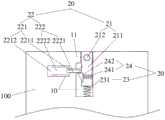
图1示出了本发明实施例一的一种终端的结构示意图。参照图1,该终端100可以包括容纳腔10和摄像头控制装置20。FIG. 1 shows a schematic structural diagram of a terminal according to Embodiment 1 of the present invention. Referring to FIG. 1 , the
摄像头控制装置20可以包括摄像头组件21、开关阀组件22、伸缩方向相互垂直的第一弹性组件23和第二弹性组件24。The
容纳腔10可以设置于终端内,容纳腔10的开口位于终端的侧壁。摄像头控制装置20设置于容纳腔10内,摄像头组件21可以配置为通过容纳腔10的开口伸出或缩入终端。另外,摄像头组件21可以与终端电连接,具体地,摄像头组件21可以通过排线与终端中控制摄像头开启或关闭的模块电连接,排线可以穿过容纳腔10通向终端内部的通道与终端电连接,并通过冗余的长度保证摄像头组件21在伸缩时与终端的电连接,其中,控制摄像头开启或关闭的模块可以集成在终端的主板或其他控制模块上,当然也可以另行设置,本发明实施例对此不作具体限定。The
开关阀组件22可以设置于容纳腔10的侧壁,开关阀组件22可以包括至少一个阀体和至少一个阀芯,至少一个阀芯可伸出或缩回至少一个阀体。其中,一个阀芯可以对应套筒连接一个阀体,从而每个阀芯均可分别伸出或缩回对应的阀体,当然,在实际应用中,多个阀芯也可以套筒连接在一个阀体中,本发明实施例对此不作具体限定。The on-off
第一弹性组件23位于容纳腔10的底部和摄像头组件21之间,并与摄像头组件21连接,也即第一弹性组件的一端可以连接摄像头组件21,另一端可以连接容纳腔的底部。第一弹性组件23可以配置为在被释放沿摄像头组件21的收缩方向的压力时,驱动摄像头组件21伸出终端,从而摄像头组件21中的摄像头可以进行拍摄。另外,第二弹性组件24可以设置在摄像头组件21上。The first
开关阀组件22关闭时,至少一个阀芯可以伸出,伸出的至少一个阀芯在摄像头组件21缩入终端内时可以与第二弹性组件24卡接,以向第一弹性组件23施加沿摄像头组件21的收缩方向的压力。开关阀组件22开启时,每个阀芯可以收回,从而与第二弹性组件24分离,以释放施加在第一弹性组件23上沿摄像头组件21的收缩方向的压力。When the
由于第二弹性组件24设置在摄像头组件21上,摄像头组件21可以连接第一弹性组件23的一端,且第一弹性组件23和第二弹性组件24的伸缩方向相互垂直,因此,在开关阀组件22与第二弹性组件24卡接时,第二弹性组件24可以将开关阀组件22施加于自身,且垂直于自身伸缩方向的压力,通过摄像头组件21施加于第一弹性组件23,由于该压力与第一弹性组件23的伸缩方向相同,因此第一弹性组件23可以被压缩,从而能够将摄像头组件21限制在容纳腔10内。在开关阀组件22开启时,开关阀组件22间接施加于第一弹性组件23的压力可以被释放,从而第一弹性组件23可以驱动摄像头组件21伸出容纳腔10,从而进行拍摄。Since the second
由于在不需要使用摄像头时,也即开关阀组件22关闭,且摄像头组件21缩入终端内时,开关阀组件22可以向第二弹性组件24施加压力,进而第二弹性组件24可以通过连接的摄像头组件21将压力施加于第一弹性组件23,从而第一弹性组件23在压力作用下被压缩时可以将摄像头组件21限制在终端内,因此,当相机软件等摄像头控制软件中毒时,摄像头在被控制开启的情况下也不会伸出终端的容纳腔10,从而能够避免被不法分子偷拍,进而避免暴露用户隐私。当需要使用摄像头进行拍摄时,用户可以开启开关阀组件22,从而开关阀组件22通过第二弹性组件24和摄像头组件21施加于第一弹性组件23上的压力被释放,从而第一弹性组件23可以带动摄像头组件21伸出终端,从而能够进行正常的拍摄。When the camera does not need to be used, that is, when the
具体地,参照图1,摄像头组件21可以包括摄像头固定件211和至少一个摄像头212,其中,摄像头固定件211可以包括两个腔体,至少一个摄像头212可以嵌入其中一个腔体中。至少一个摄像头212可以包括背对背嵌入摄像头固定件211的前置摄像头和后置摄像头,每个摄像头均可以与终端电连接。在实际应用中,第一弹性组件23在开关阀组件22开启时,至少带动摄像头组件21中的摄像头部分伸出容纳腔10即可。Specifically, referring to FIG. 1 , the
进一步地,容纳腔10与摄像头组件21相对的侧壁上可以设置有滑轨,滑轨的轨道方向可以与摄像头组件21的伸缩方向相同,本发明实施例对此不作具体限定,相应的,摄像头组件21与滑轨接触的侧壁上可以设置有突起结构,具体地,滑块可以设置在摄像头固定件211与滑轨接触的侧壁上,突起结构在摄像头组件21伸缩时可以沿滑轨滑动。在实际应用中,摄像头组件21侧壁上的突起结构可以为与摄像头固定件211粘接的滑块,也可以为摄像头固定件211上加工出的突起部分,本发明实施例对此不作具体限定。通过在容纳腔10与摄像头组件21相对的侧壁上设置滑轨,以及在摄像头组件21与滑轨接触的侧壁上设置突起结构,从而在摄像头组件21伸缩时,突起结构可以带动摄像头组件21沿滑轨伸出终端,进而可以精确控制摄像头组件21的运动路径,提高摄像头组件21伸缩时的稳定性。Further, a slide rail may be provided on the side wall of the
在一种实现方式中,开关阀组件22可以包括机械阀221,机械阀221的阀芯2211可以配置为在外力作用下缩回机械阀221的阀体2212,以进行开启。其中,阀芯2211的伸缩方向只要保证阀芯2211在伸出阀体2212时,可以与第二弹性组件24卡接即可,例如阀芯2211的设置方向可以垂直于摄像头组件21的伸缩方向,或者可以与摄像头组件21伸缩方向的垂直方向呈较小的角度,本发明实施例对此不作具体限定。机械阀221的开启和关闭可以由终端用户手动进行控制,用户可以向机械阀221施加使阀芯2211缩回阀体2212的外力,从而开启机械阀221,阀芯2211可以第二弹性组件24的一端分离。用户还可以向机械阀221施加使阀芯2211伸出阀体2212的外力,从而关闭机械阀221,阀芯2211可以与第二弹性组件24的一端卡接。在实际应用中,用户可以通过上述方式,也即施加使机械阀221关闭的外力来关闭机械阀221,当然,用户还可以通过停止施加使机械阀221开启的外力的方式关闭机械阀221,也即机械阀221在没有外力的情况下,阀芯2211可以自动恢复至伸出阀体2212的状态,本发明实施例对于机械阀221的关闭方式不作具体限定。In an implementation manner, the
由于机械阀221需要用户手动开启,无法通过软件控制,因此在控制摄像头开启的软件中毒时,机械阀221仍然可以通过阀芯2211向第二弹性组件24施加压力,从而将摄像头组件21限制在容纳腔10内,从而可以避免摄像头组件21的伸缩被软件非法控制,能够进一步提高摄像头的安全性。Since the
在另一种实现方式中,开关阀组件22可以包括电磁阀222,电磁阀222的阀芯2221可以配置为在接收到电磁阀开启信号时缩回电磁阀222的阀体2222,以进行开启。其中,阀芯2221的伸缩方向只要保证阀芯2221在伸出阀体2222时,可以与第二弹性组件24卡接即可,例如阀芯2221的设置方向可以垂直于摄像头组件21的伸缩方向,或者可以与摄像头组件21伸缩方向的垂直方向呈较小的角度,本发明实施例对此不作具体限定。电磁阀222关闭时,电磁阀222的阀芯2221可以伸出电磁阀222的阀体2222,从而伸出的阀芯2221可以与第二弹性组件24的一端卡接,以通过第二弹性组件24和摄像头组件21向第一弹性组件23施加压力,将摄像头组件21限制在容纳腔10内。电磁阀222开启时,电磁阀222的阀芯2221可以收回电磁阀222的阀体2222,从而阀芯2221可以与第二弹性组件24的一端分离,以释放施加在第一弹性组件23上的压力,第一弹性组件23可以驱动摄像头组件21伸出容纳腔10。In another implementation, the
在实际应用中,可以通过设定电磁阀开启信号的有效持续时长来关闭电磁阀222,也即在电磁阀开启信号持续的时长之内,电磁阀222可以开启,超过该时长之后,电磁阀开启信号断开,从而电磁阀222可以关闭。当然,在另外一种实现方式中,还可以通过电磁阀关闭信号关闭电磁阀222,也即是电磁阀222的阀芯2221可以配置为在接收到电磁阀关闭信号时伸出电磁阀222的阀体2222,以进行关闭。In practical applications, the
电磁阀222可以控制摄像头组件21伸出或缩入终端,而不控制摄像头212的开启或关闭,也即控制摄像头伸出和控制摄像头拍摄的功能是各自独立的,因此,在控制摄像头开启的软件中毒时,关闭时的电磁阀222仍然可以在摄像头组件21缩入终端内时,通过第二弹性组件24和摄像头组件21向第一弹性组件23施加压力,从而将摄像头组件21限制在容纳腔10内,如此,即使摄像头212被控制开启,电磁阀222也可以将摄像头组件21限制在终端内,从而摄像头212也无法进行拍摄。通过关闭电磁阀222,可以避免摄像头212被软件非法控制时伸出终端,能够进一步提高摄像头212的安全性。The
在第三种实现方式中,开关阀组件22可以在包括机械阀221的基础上,还包括电磁阀222,也即两种开关阀同时开启时实现开关阀组件22的开启,两种开关阀同时关闭时实现开关阀组件22的关闭。In a third implementation manner, the on-off
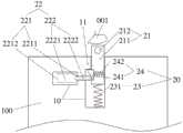
对于包括电磁阀222的开关阀组件22,机械阀221和电磁阀222可以独立设置。例如,图2示出了一种机械阀221和电磁阀222独立设置的示意图,参照图2,机械阀221可以与电磁阀222平行设置,也即机械阀221的阀芯2211与电磁阀222的阀芯2221的伸缩方向相互平行,当机械阀221和电磁阀222均开启时,两个阀芯均可以缩回各自对应的阀体,从而实现开关阀组件22与第二弹性组件24的分离。其中,参照图2,机械阀221的阀芯2211的控制部分可以外露于终端机体,从而便于用户进行手动控制。需要说明的是,在实际设置机械阀221和电磁阀222时,机械阀221和电磁阀222可以平行设置,也可以非平行设置,只要保证两个阀芯均能够在伸出时与第二弹性组件24卡接即可。For the on-off
另外,当开关阀组件22同时包括机械阀221和电磁阀222时,电磁阀222与机械阀221还可以套筒连接,其中,二者的阀芯可以套筒连接,二者的阀体也可以套筒连接,在进行电磁阀222与机械阀221的套筒设计时,保证各自的阀芯收缩互不影响即可。电磁阀222与机械阀221进行套筒连接,能够缩小开关阀组件22所占用的空间,以便于设置或增加其他终端器件。In addition, when the
进一步地,当开关阀组件22包括电磁阀222时,终端还可以包括身份识别模块和控制模块(图1中均未示出),其中,电磁阀222、控制模块和身份识别模块可以依次电连接。身份识别模块可以配置为对采集到的身份信息进行验证,以及在身份信息验证通过时,向控制模块输入验证通过信号。控制模块可以配置为在接收到验证通过信号时,向电磁阀222输入使电磁阀222的阀芯2221缩回电磁阀222的阀体2222的电磁阀开启信号。Further, when the
其中,身份识别模块可以通过至少一种不需要摄像头的身份识别模式进行身份识别,例如指纹识别、密码识别、静脉识别、声音识别等等。以指纹识别为例,身份识别模块具体可以为指纹识别模块,终端用户可以事先在终端中设置并存储自己的指纹图像,之后可以开启通过指纹开启电磁阀222的功能。当用户需要使用摄像头进行拍摄时,可以在终端的指纹识别区域按压手指,以向指纹识别模块输入指纹图像,指纹模块在采集到指纹图像时,可以将该指纹图像与存储的指纹图像进行对比,以对该指纹图像进行验证。当该指纹图像与存储的指纹图像一致时,确定对该指纹图像验证通过,此时,指纹识别模块可以向控制模块输入验证通过信号。控制模块在接收到指纹识别模块发送的验证通过信号时,可以向电磁阀222输入电磁阀开启信号,从而可以开启电磁阀222。The identity recognition module can perform identity recognition through at least one identity recognition mode that does not require a camera, such as fingerprint recognition, password recognition, vein recognition, and voice recognition. Taking fingerprint recognition as an example, the identity recognition module may be a fingerprint recognition module. The terminal user can set and store his own fingerprint image in the terminal in advance, and then can enable the function of opening the
通过身份验证开启电磁阀222,可以在摄像头组件21伸出容纳腔10的过程中引入身份验证机制,从而只有身份验证通过的用户才能够开启摄像头进行拍摄,而未通过身份验证的用户则无法开启摄像头进行拍摄,如此,能够防止摄像头在机主不知情的情况下被利用,进而能够提高摄像头的安全性,防止摄像头被能够接触到终端的不法分子使用。By opening the
另外,由于摄像头组件21可以包括前置摄像头和后置摄像头,因此,在指纹识别模块对指纹图像验证通过之后,终端可以显示选择摄像头的提示界面。如图3所示,当用户通过手指001按压指纹识别区域时,指纹识别模块002可以采集到指纹图像并进行验证,验证通过之后,终端可以显示选择摄像头的提示界面003,在一种实现方式中,提示界面003可以显示“手指向上滑动启动前置摄像头”以及“手指向下滑动启动后置摄像头”的提示信息,从而用户可以通过手指001的滑动方向选择开启前置摄像头或后置摄像头。在另一种实现方式中,指纹识别模块002对指纹图像验证通过之后,可以默认开启摄像头中的一者,用户可以通过摄像头转换图标或者预设转换操作转换摄像头,本发明实施例对此不作具体限定。In addition, since the
需要说明的是,在实际应用中,身份识别模块和控制模块可以集成在终端的主板或其他现有的模块上,当然也可以另行设置,本发明实施例对此不作具体限定。It should be noted that, in practical applications, the identity recognition module and the control module may be integrated on the main board of the terminal or other existing modules, and of course may also be set separately, which are not specifically limited in this embodiment of the present invention.
进一步地,第二弹性组件24可以包括至少一个第二弹簧241和卡块242,图1仅示例性地示出了第二弹性组件24包括一个第二弹簧241的情况。其中,卡块242在摄像头组件21缩入终端的过程中与开关阀组件22接触的一面为斜面,且卡块242在至少一个第二弹簧241的伸缩方向上的厚度,沿容纳腔10的顶部到底部的方向逐渐减小,也即如图1所示,卡块242可以为一截面为三角形的块状结构,从而卡块242靠近容纳腔10顶部的端面在开关阀组件22关闭时可以与开关阀组件22卡接。Further, the second
每个第二弹簧241可以平行设置,从而在设置之后,每个第二弹簧241的伸缩方向均相同,且每个第二弹簧241的伸缩方向与摄像头组件21的伸缩方向垂直。每个第二弹簧241的一端可以嵌入摄像头组件21的腔体内,以在腔体内伸缩,另一端可以连接卡块242的一端。对于摄像头组件21的两个腔体,其中一个腔体可以用于容纳至少一个摄像头212,另一个腔体可以用于容纳至少一个第二弹簧241。Each of the
参照图1,卡块242的一端可以连接第二弹簧241,卡块242的另一端靠近开关阀组件22,开关阀组件22关闭时,卡块242在摄像头组件21缩入终端时与伸出的至少一个阀芯卡接。开关阀组件22开启时,卡块242的另一端可以与伸出的每个阀芯分离。Referring to FIG. 1, one end of the blocking
进一步地,第一弹性组件23可以包括至少一个第一弹簧231,图1仅示例性地示出了第一弹性组件23包括一个第一弹簧231的情况。每个第一弹簧231可以平行设置,从而在设置之后,每个第一弹簧231的伸缩方向均相同,且每个第一弹簧231的伸缩方向与摄像头组件21的伸缩方向相同。其中,每个第一弹簧231的一端可以连接摄像头组件21的底部,从而与摄像头组件21固定,另一端可以连接容纳腔10的底部,从而与终端机体固定。Further, the first
参照图1,容纳腔10还可以包括限位槽11,限位槽11可以位于开关阀组件22与容纳腔10的开口之间的容纳腔10的侧壁上,卡块242在摄像头组件21伸出终端内时,可以卡接在限位槽11内。图4示出了一种卡块卡接在限位槽内的示意图,参照图4,当开关阀组件22开启时,开关阀组件22可以与卡块242分离,从而释放施加在第一弹簧231上的压力,第一弹簧231可以驱动摄像头组件21伸出终端的容纳腔10,伸出一定距离之后,卡块242可以卡接在限位槽11内,从而摄像头组件21无法继续伸出,此时,摄像头组件21的摄像头部分已经伸出终端,可以正常进行拍摄。通过设置限位槽11,可以在摄像头组件21伸出终端时,限制摄像头组件21伸出的最远位置,在第一弹性组件23的弹力作用过大时,能够避免摄像头组件21在过大的弹力作用下脱出终端机体,从而可以避免摄像头组件21无法收缩入终端内的情况发生,并且可以避免摄像头组件21脱出后受损。1 , the
另外,开关阀组件22开启,且摄像头组件21伸出终端之后,开关阀组件22中的电磁阀222可以马上复位,电磁阀222复位后将处于关闭状态,电磁阀222的复位不会影响摄像头组件21伸出终端的状态。当然,在实际应用中,用户还可以在摄像头组件21伸出终端之后马上复位机械阀221,机械阀221复位后将处于关闭状态,也可以在下次进行拍摄之前的任意时间复位机械阀221,本发明实施例对此不作具体限定。In addition, after the on-off
当然,在实际应用中,为了避免摄像头组件21在伸出终端时脱出终端机体,还可以对每个第一弹簧231的长度或弹性限度进行控制,也即是可以选择伸长后无法使摄像头组件21完全脱出终端机体的弹簧作为第一弹簧231,本发明实施例对此不作具体限定。Of course, in practical applications, in order to prevent the
图5示出了一种手指按压摄像头组件的示意图。参照图5,在终端用户使用摄像头完成拍摄之后需要收回摄像头时,用户可以用手指001按压摄像头组件21,从而可以控制摄像头组件21缩入容纳腔10,此时,由于开关阀组件22中至少有电磁阀222可以复位,因此摄像头组件21在被按压的过程中,至少有电磁阀222的阀芯2221可以与卡块242的斜面进行滑动接触,卡块242在沿容纳腔10顶部向容纳腔10底部运动的过程中,由于斜面与开关阀组件22滑动摩擦,因此,摄像头组件21逐渐压缩第一弹簧231,同时卡块242逐渐向摄像头组件21的腔体内收缩,从而摄像头组件21可以逐渐缩入容纳腔10。当卡块242通过开关阀组件22的位置,也即卡块242的斜面完全滑过开关阀组件22时,卡块242靠近容纳腔10顶部的端面将位于开关阀组件22的位置之下,此时,开关阀组件22对第二弹簧241没有垂直于摄像头组件21伸缩方向的压力,因此,第一弹簧231可以被释放,卡块242靠近容纳腔10顶部的端面将与开关阀组件22卡接,进而摄像头组件21可以恢复至图1所示的状态,被限制在终端的容纳腔10内。FIG. 5 shows a schematic diagram of a finger pressing the camera assembly. Referring to FIG. 5 , when the end user needs to retract the camera after using the camera to complete the shooting, the user can press the
在实际应用中,容纳腔10可以利用终端的显示屏、后盖等形成,从而可以将摄像头组件21容纳在终端内,并且在不需要使用摄像头时,摄像头组件21缩入容纳腔10,还能够避免摄像头的镜头被外部物体划伤。In practical applications, the
在本发明实施例中,第一弹性组件在开关阀组件的压力下,可以将摄像头组件限制在终端的容纳腔内,因此,当摄像头控制软件中毒时,摄像头在被控制开启的情况下也不会伸出终端机体,从而能够避免被不法分子偷拍,进而避免暴露用户隐私,提高了终端的安全性。当需要使用摄像头进行拍摄时,可以开启开关阀组件,从而第一弹性组件上的压力被释放时可以驱动摄像头组件伸出终端机体,能够保证正常的拍摄功能。In this embodiment of the present invention, under the pressure of the switch valve assembly, the first elastic component can confine the camera assembly in the accommodating cavity of the terminal. Therefore, when the camera control software is poisoned, the camera will not be turned on even if it is controlled. The terminal body will be extended, so as to avoid being secretly photographed by criminals, thereby avoiding exposing user privacy, and improving the security of the terminal. When the camera needs to be used for shooting, the switch valve assembly can be opened, so that when the pressure on the first elastic assembly is released, the camera assembly can be driven to extend out of the terminal body, which can ensure the normal shooting function.
本领域技术人员应该知悉,说明书中所描述的实施例属于优选实施例,所涉及的动作和模块并不一定是本发明所必须的。还需要说明的是,在本文中,诸如第一和第二等之类的关系术语仅仅用来将一个实体或者操作与另一个实体或操作区分开来,而不一定要求或者暗示这些实体或操作之间存在任何这种实际的关系或者顺序。而且,术语“包括”、“包含”或者其任何其他变体意在涵盖非排他性的包含,从而使得包括一系列要素的过程、方法、商品或者设备不仅包括那些要素,而且还包括没有明确列出的其他要素,或者是还包括为这种过程、方法、商品或者设备所固有的要素。在没有更多限制的情况下,由语句“包括一个......”限定的要素,并不排除在包括所述要素的过程、方法、商品或者设备中还存在另外的相同要素。Those skilled in the art should know that the embodiments described in the specification belong to the preferred embodiments, and the actions and modules involved are not necessarily required by the present invention. It should also be noted that in this document, relational terms such as first and second are used only to distinguish one entity or operation from another, and do not necessarily require or imply those entities or operations There is no such actual relationship or order between them. Furthermore, the terms "comprising", "comprising" or any other variation thereof are intended to encompass a non-exclusive inclusion such that a process, method, article of manufacture or device comprising a list of elements includes not only those elements, but also includes not explicitly listed or other elements inherent to such a process, method, commodity or apparatus. Without further limitation, an element qualified by the phrase "comprising a..." does not preclude the presence of additional identical elements in the process, method, article of manufacture or device that includes the element.
以上对本发明所提供的一种终端,进行了详细介绍,本文中应用了具体个例对本发明的原理及实施方式进行了阐述,以上实施例的说明只是用于帮助理解本发明的方法及其核心思想;同时,对于本领域的一般技术人员,依据本发明的思想,在具体实施方式及应用范围上均会有改变之处,综上所述,本说明书内容不应理解为对本发明的限制。A terminal provided by the present invention has been introduced in detail above. Specific examples are used in this paper to illustrate the principles and implementations of the present invention. The descriptions of the above embodiments are only used to help understand the method and its core of the present invention. At the same time, for those of ordinary skill in the art, according to the idea of the present invention, there will be changes in the specific implementation and application scope. To sum up, the content of this specification should not be construed as a limitation of the present invention.
Claims (8)
Priority Applications (2)
| Application Number | Priority Date | Filing Date | Title |
|---|---|---|---|
| CN201810551033.3ACN108600590B (en) | 2018-05-31 | 2018-05-31 | Terminal |
| US16/255,957US10924643B2 (en) | 2018-05-31 | 2019-01-24 | Terminal with controlled elastic camera component |
Applications Claiming Priority (1)
| Application Number | Priority Date | Filing Date | Title |
|---|---|---|---|
| CN201810551033.3ACN108600590B (en) | 2018-05-31 | 2018-05-31 | Terminal |
Publications (2)
| Publication Number | Publication Date |
|---|---|
| CN108600590A CN108600590A (en) | 2018-09-28 |
| CN108600590Btrue CN108600590B (en) | 2020-11-13 |
Family
ID=63630104
Family Applications (1)
| Application Number | Title | Priority Date | Filing Date |
|---|---|---|---|
| CN201810551033.3AActiveCN108600590B (en) | 2018-05-31 | 2018-05-31 | Terminal |
Country Status (2)
| Country | Link |
|---|---|
| US (1) | US10924643B2 (en) |
| CN (1) | CN108600590B (en) |
Families Citing this family (17)
| Publication number | Priority date | Publication date | Assignee | Title |
|---|---|---|---|---|
| CN111034378B (en)* | 2017-07-06 | 2021-09-03 | 惠普发展公司,有限责任合伙企业 | Movable mounting assembly |
| CN209462415U (en)* | 2018-09-07 | 2019-10-01 | Oppo广东移动通信有限公司 | mobile terminal |
| CN109359458B (en)* | 2018-10-19 | 2021-06-29 | 北京小米移动软件有限公司 | Application unlocking method, device and computer-readable storage medium |
| CN109218477B (en)* | 2018-10-29 | 2020-08-07 | 维沃移动通信(杭州)有限公司 | Camera device and terminal |
| CN109379517B (en)* | 2018-11-06 | 2021-03-12 | Oppo(重庆)智能科技有限公司 | Electronic device |
| CN111431548B (en)* | 2019-01-10 | 2021-11-23 | 北京小米移动软件有限公司 | Pop-up device and terminal equipment |
| CN109782853B (en)* | 2019-02-15 | 2020-07-10 | 广东虹勤通讯技术有限公司 | Press camera assembly and electronic equipment |
| JP7244300B2 (en)* | 2019-02-28 | 2023-03-22 | 日本電産コパル株式会社 | Camera module shielding mechanism, electronic equipment |
| CN110035156B (en)* | 2019-04-22 | 2020-09-01 | 维沃移动通信(杭州)有限公司 | Terminal equipment |
| WO2021045281A1 (en)* | 2019-09-06 | 2021-03-11 | 삼성전자주식회사 | Electronic device and camera moving assembly |
| CN110691235B (en)* | 2019-09-11 | 2021-02-23 | 华为技术有限公司 | Detection method, device and equipment |
| CN113542577A (en)* | 2020-04-16 | 2021-10-22 | 北京小米移动软件有限公司 | A method, device and storage medium for controlling a telescopic camera |
| US11435781B1 (en)* | 2021-03-23 | 2022-09-06 | Lenovo (Singapore) Pte. Ltd. | Computing device |
| CN115346814A (en)* | 2021-05-13 | 2022-11-15 | 北京小米移动软件有限公司 | terminal |
| CN113309952B (en)* | 2021-06-30 | 2024-12-10 | 高创(苏州)电子有限公司 | Electronic devices |
| CN113452823B (en)* | 2021-07-19 | 2024-04-26 | 维沃移动通信有限公司 | Electronic equipment |
| CN114827214A (en)* | 2021-10-29 | 2022-07-29 | 北京京东方技术开发有限公司 | Method for controlling application terminal, storage medium and camera |
Citations (4)
| Publication number | Priority date | Publication date | Assignee | Title |
|---|---|---|---|---|
| CN103533225A (en)* | 2013-11-01 | 2014-01-22 | 京东方科技集团股份有限公司 | Camera and electronic equipment |
| CN104023190A (en)* | 2014-06-20 | 2014-09-03 | 冠捷显示科技(厦门)有限公司 | Automatic lifting camera and display device thereof |
| CN105141815A (en)* | 2015-09-02 | 2015-12-09 | 小米科技有限责任公司 | Device and terminal for automatically popping up camera |
| CN207304649U (en)* | 2018-01-17 | 2018-05-01 | 深圳市诚壹科技有限公司 | Concealed pick-up head structure and mobile phone |
Family Cites Families (13)
| Publication number | Priority date | Publication date | Assignee | Title |
|---|---|---|---|---|
| US5880928A (en)* | 1997-06-13 | 1999-03-09 | Ma; His-Kuang | Notebook computer with audio and video effects |
| JP4338954B2 (en)* | 2002-10-17 | 2009-10-07 | 富士フイルム株式会社 | camera |
| US20050014527A1 (en)* | 2003-07-18 | 2005-01-20 | Agere Systems Incorporated | Retractable rotatable camera module for mobile communication device and method of operation thereof |
| TWI543579B (en)* | 2010-05-10 | 2016-07-21 | 鴻海精密工業股份有限公司 | Portable electronic device |
| TWI548966B (en)* | 2014-12-29 | 2016-09-11 | 鴻海精密工業股份有限公司 | Electronic device |
| US9736383B2 (en)* | 2015-10-30 | 2017-08-15 | Essential Products, Inc. | Apparatus and method to maximize the display area of a mobile device |
| US9762781B2 (en)* | 2015-10-30 | 2017-09-12 | Essential Products, Inc. | Apparatus and method to maximize the display area of a mobile device by increasing the size of the display without necessarily increasing the size of the phone |
| WO2017179803A1 (en)* | 2016-04-15 | 2017-10-19 | Lg Electronics Inc. | Displacement sensor and camera module having the same |
| CN106850896B (en)* | 2017-03-07 | 2019-12-03 | Oppo广东移动通信有限公司 | Terminal device |
| ES2816098T3 (en)* | 2017-11-03 | 2021-03-31 | Guangdong Oppo Mobile Telecommunications Corp Ltd | Sliding mobile phone camera by electromagnetic force |
| WO2019184561A1 (en)* | 2018-03-31 | 2019-10-03 | Guangdong Oppo Mobile Telecommunications Corp., Ltd. | Electronic device |
| TWI662877B (en)* | 2018-05-22 | 2019-06-11 | 仁寶電腦工業股份有限公司 | Functional element rotation reset device and electronic apparatus |
| CN108834354B (en)* | 2018-07-10 | 2020-10-30 | 北京小米移动软件有限公司 | Functional component, control method and terminal for functional component |
- 2018
- 2018-05-31CNCN201810551033.3Apatent/CN108600590B/enactiveActive
- 2019
- 2019-01-24USUS16/255,957patent/US10924643B2/enactiveActive
Patent Citations (4)
| Publication number | Priority date | Publication date | Assignee | Title |
|---|---|---|---|---|
| CN103533225A (en)* | 2013-11-01 | 2014-01-22 | 京东方科技集团股份有限公司 | Camera and electronic equipment |
| CN104023190A (en)* | 2014-06-20 | 2014-09-03 | 冠捷显示科技(厦门)有限公司 | Automatic lifting camera and display device thereof |
| CN105141815A (en)* | 2015-09-02 | 2015-12-09 | 小米科技有限责任公司 | Device and terminal for automatically popping up camera |
| CN207304649U (en)* | 2018-01-17 | 2018-05-01 | 深圳市诚壹科技有限公司 | Concealed pick-up head structure and mobile phone |
Also Published As
| Publication number | Publication date |
|---|---|
| US10924643B2 (en) | 2021-02-16 |
| US20190373141A1 (en) | 2019-12-05 |
| CN108600590A (en) | 2018-09-28 |
Similar Documents
| Publication | Publication Date | Title |
|---|---|---|
| CN108600590B (en) | Terminal | |
| CN107277324B (en) | Camera module and terminal | |
| US11256159B2 (en) | Camera shutters | |
| CN206302443U (en) | a mobile terminal | |
| CN109246361B (en) | Camera module control method and device | |
| US9578147B2 (en) | Casing and portable electronic device using same | |
| CN109995904B (en) | Functional module, electronic device and control method of electronic device | |
| CN106446618A (en) | Mobile terminal control method and device and mobile terminal | |
| CN114545709A (en) | Electronically controlled privacy shutter | |
| US9397420B2 (en) | Card slot structure having an automatic card ejection function | |
| CN108810380A (en) | A kind of terminal device and control method | |
| CN109743423B (en) | Display device and control method thereof | |
| CN105138137A (en) | Method and device for conducting camera shooting by combining fingerprint and volume keys in stand-by state | |
| TWI382298B (en) | Business card case mounted on notebook computer | |
| CN1941793A (en) | Electronic device with camera head | |
| TWI811682B (en) | Image capturing device | |
| US9756238B2 (en) | Image capturing apparatus for performing authentication of a photographer and organizing image data for each photographer and control method thereof | |
| CN112612320B (en) | Electronic device with image acquisition function | |
| CN208782853U (en) | A kind of turnover concealed mobile phone camera | |
| CN221827232U (en) | Notebook computer | |
| KR101329734B1 (en) | Folding type battery cover assembly module and electronic device comprising the same | |
| CN115396568B (en) | camera device | |
| US12101539B2 (en) | Information handling system camera shutter with secondary security by power removal | |
| US12284449B2 (en) | Information handling system camera shutter with audio feedback of position change | |
| CN211779808U (en) | Clamping device |
Legal Events
| Date | Code | Title | Description |
|---|---|---|---|
| PB01 | Publication | ||
| PB01 | Publication | ||
| SE01 | Entry into force of request for substantive examination | ||
| SE01 | Entry into force of request for substantive examination | ||
| GR01 | Patent grant | ||
| GR01 | Patent grant | ||
| CP03 | Change of name, title or address | Address after:215200 No. 1700 Zhongshan North Road, Wujiang Economic and Technological Development Zone, Suzhou City, Jiangsu Province Patentee after:Gaochuang (Suzhou) Electronics Co.,Ltd. Patentee after:BOE TECHNOLOGY GROUP Co.,Ltd. Address before:100015 No. 10, Jiuxianqiao Road, Beijing, Chaoyang District Patentee before:BOE TECHNOLOGY GROUP Co.,Ltd. Patentee before:Gaochuang (Suzhou) Electronics Co.,Ltd. | |
| CP03 | Change of name, title or address |