CN108590790B - Liquefied gas energy storage power generation device and energy storage power generation method thereof - Google Patents
Liquefied gas energy storage power generation device and energy storage power generation method thereofDownload PDFInfo
- Publication number
- CN108590790B CN108590790BCN201810337946.5ACN201810337946ACN108590790BCN 108590790 BCN108590790 BCN 108590790BCN 201810337946 ACN201810337946 ACN 201810337946ACN 108590790 BCN108590790 BCN 108590790B
- Authority
- CN
- China
- Prior art keywords
- gas
- energy storage
- compression
- expansion
- liquefied
- Prior art date
- Legal status (The legal status is an assumption and is not a legal conclusion. Google has not performed a legal analysis and makes no representation as to the accuracy of the status listed.)
- Active
Links
- 238000004146energy storageMethods0.000titleclaimsabstractdescription428
- 238000010248power generationMethods0.000titleclaimsabstractdescription294
- 238000000034methodMethods0.000titleclaimsabstractdescription55
- 239000007788liquidSubstances0.000claimsabstractdescription510
- 238000007906compressionMethods0.000claimsabstractdescription342
- 230000006835compressionEffects0.000claimsabstractdescription334
- 239000007789gasSubstances0.000claimsdescription994
- 230000005611electricityEffects0.000claimsdescription96
- 238000012546transferMethods0.000claimsdescription44
- 230000007246mechanismEffects0.000claimsdescription24
- 238000009423ventilationMethods0.000claimsdescription8
- 238000002309gasificationMethods0.000claimsdescription5
- 229910052698phosphorusInorganic materials0.000claimsdescription2
- 230000008901benefitEffects0.000abstractdescription14
- 230000007613environmental effectEffects0.000abstractdescription6
- 238000010586diagramMethods0.000description45
- 230000008569processEffects0.000description39
- 238000005516engineering processMethods0.000description21
- IJGRMHOSHXDMSA-UHFFFAOYSA-NAtomic nitrogenChemical compoundN#NIJGRMHOSHXDMSA-UHFFFAOYSA-N0.000description12
- 239000000463materialSubstances0.000description9
- 239000000126substanceSubstances0.000description9
- 229910052757nitrogenInorganic materials0.000description6
- 239000013589supplementSubstances0.000description6
- XLYOFNOQVPJJNP-UHFFFAOYSA-NwaterSubstancesOXLYOFNOQVPJJNP-UHFFFAOYSA-N0.000description6
- 230000008859changeEffects0.000description4
- 230000007423decreaseEffects0.000description3
- 230000005012migrationEffects0.000description3
- 238000013508migrationMethods0.000description3
- 238000002156mixingMethods0.000description3
- 239000000203mixtureSubstances0.000description3
- 238000000926separation methodMethods0.000description3
- UFHFLCQGNIYNRP-UHFFFAOYSA-NHydrogenChemical compound[H][H]UFHFLCQGNIYNRP-UHFFFAOYSA-N0.000description2
- 230000009471actionEffects0.000description2
- 238000001816coolingMethods0.000description2
- 238000011161developmentMethods0.000description2
- 239000001307heliumSubstances0.000description2
- 229910052734heliumInorganic materials0.000description2
- SWQJXJOGLNCZEY-UHFFFAOYSA-Nhelium atomChemical compound[He]SWQJXJOGLNCZEY-UHFFFAOYSA-N0.000description2
- 239000001257hydrogenSubstances0.000description2
- 229910052739hydrogenInorganic materials0.000description2
- 230000005678Seebeck effectEffects0.000description1
- QVGXLLKOCUKJST-UHFFFAOYSA-Natomic oxygenChemical compound[O]QVGXLLKOCUKJST-UHFFFAOYSA-N0.000description1
- UBAZGMLMVVQSCD-UHFFFAOYSA-Ncarbon dioxide;molecular oxygenChemical compoundO=O.O=C=OUBAZGMLMVVQSCD-UHFFFAOYSA-N0.000description1
- 238000009833condensationMethods0.000description1
- 230000005494condensationEffects0.000description1
- 238000001704evaporationMethods0.000description1
- 230000008020evaporationEffects0.000description1
- 238000010438heat treatmentMethods0.000description1
- 238000009413insulationMethods0.000description1
- 239000001301oxygenSubstances0.000description1
- 229910052760oxygenInorganic materials0.000description1
- 239000000047productSubstances0.000description1
- 238000011160researchMethods0.000description1
- 238000006467substitution reactionMethods0.000description1
- 238000009834vaporizationMethods0.000description1
- 230000008016vaporizationEffects0.000description1
Images


Classifications
- F—MECHANICAL ENGINEERING; LIGHTING; HEATING; WEAPONS; BLASTING
- F01—MACHINES OR ENGINES IN GENERAL; ENGINE PLANTS IN GENERAL; STEAM ENGINES
- F01K—STEAM ENGINE PLANTS; STEAM ACCUMULATORS; ENGINE PLANTS NOT OTHERWISE PROVIDED FOR; ENGINES USING SPECIAL WORKING FLUIDS OR CYCLES
- F01K25/00—Plants or engines characterised by use of special working fluids, not otherwise provided for; Plants operating in closed cycles and not otherwise provided for
- F01K25/02—Plants or engines characterised by use of special working fluids, not otherwise provided for; Plants operating in closed cycles and not otherwise provided for the fluid remaining in the liquid phase
- F—MECHANICAL ENGINEERING; LIGHTING; HEATING; WEAPONS; BLASTING
- F01—MACHINES OR ENGINES IN GENERAL; ENGINE PLANTS IN GENERAL; STEAM ENGINES
- F01K—STEAM ENGINE PLANTS; STEAM ACCUMULATORS; ENGINE PLANTS NOT OTHERWISE PROVIDED FOR; ENGINES USING SPECIAL WORKING FLUIDS OR CYCLES
- F01K27/00—Plants for converting heat or fluid energy into mechanical energy, not otherwise provided for
Landscapes
- Engineering & Computer Science (AREA)
- Chemical & Material Sciences (AREA)
- Combustion & Propulsion (AREA)
- Mechanical Engineering (AREA)
- General Engineering & Computer Science (AREA)
- Filling Or Discharging Of Gas Storage Vessels (AREA)
- Separation By Low-Temperature Treatments (AREA)
Abstract
Description
Translated fromChinese技术领域technical field
本发明的实施例涉及一种液化气体储能发电装置和液化气体储能发电装置的储能发电方法。Embodiments of the present invention relate to a liquefied gas energy storage power generation device and an energy storage power generation method of the liquefied gas energy storage power generation device.
背景技术Background technique
随着电力系统的发展,太阳能发电技术和风力发电技术等可再生能源发电技术越来越受到重视,装机规模也越来越大。然而,太阳能发电技术和风力发电技术等可再生能源发电技术产生的电力会随着天气、季节等因素而产生波动,具有一定的间歇性。With the development of the power system, more and more attention has been paid to renewable energy power generation technologies such as solar power generation technology and wind power generation technology, and the installed capacity is also increasing. However, the power generated by renewable energy power generation technologies such as solar power generation technology and wind power generation technology fluctuates with weather, season and other factors, and has a certain intermittent.
另一方面,电网的负荷也会随着昼夜、季节等因素而变化。因此,可利用储能发电技术在可再生能源发电技术产生的电力较多的情况下或者电网负荷较低的情况下将多余电能存储起来,在可再生能源发电技术产生的电力较少的情况下或者电网负荷较高的情况下利用存储的能量进行发电以提高对能源的利用效率。On the other hand, the load of the power grid will also change with factors such as day and night, seasons and so on. Therefore, energy storage power generation technology can be used to store excess electrical energy when the renewable energy power generation technology produces more electricity or when the grid load is low, and when the renewable energy power generation technology produces less electricity Or when the grid load is high, the stored energy is used to generate electricity to improve the utilization efficiency of energy.
发明内容SUMMARY OF THE INVENTION
本公开实施例提供一种液化气体储能发电装置及其储能发电方法。该液化储能发电装置可提供一种新型的利用液化空气进行储能发电的装置,液化气体储能发电技术的存储容量比较大,而所占用的体积则相对较小。该液化气体储能发电装置具有无污染、对环境友好、储能成本较低、经济效益高等优点。并且,该液化气体储能发电装置的能量利用效率较高。Embodiments of the present disclosure provide a liquefied gas energy storage power generation device and an energy storage power generation method thereof. The liquefied gas energy storage power generation device can provide a new type of device for energy storage and power generation using liquefied air. The storage capacity of the liquefied gas energy storage power generation technology is relatively large, while the occupied volume is relatively small. The liquefied gas energy storage power generation device has the advantages of no pollution, environmental friendliness, low energy storage cost and high economic benefit. In addition, the energy utilization efficiency of the liquefied gas energy storage power generation device is relatively high.
本公开至少一个实施例提供一种液化气体储能发电装置,其包括:气体压缩膨胀单元,包括气体端口;液化储能单元,与所述气体压缩膨胀单元相连;热电交换单元,与所述液化储能单元相连;以及液体源,与所述热电交换单元相连,所述气体压缩膨胀单元被配置为利用电能对来自所述气体端口的气体进行压缩、膨胀以形成第一压缩气体并将所述第一压缩气体输送至所述液化储能单元,所述热电交换单元被配置为利用电能吸收所述液化储能单元中液态气体的热量并将热量转移至所述液体源以促使所述第一压缩气体在所述液化储能单元中液化,所述热电交换单元还被配置为利用所述液体源与所述液化储能单元中液态气体的温差进行发电并将所述液体源的热量转移至所述液化储能单元中液态气体以促使所述液化储能单元中液态气体气化,所述气体压缩膨胀单元还被配置为利用所述液化储能单元中的气体进行发电。At least one embodiment of the present disclosure provides a liquefied gas energy storage power generation device, which includes: a gas compression and expansion unit, including a gas port; a liquefaction energy storage unit, connected to the gas compression and expansion unit; a thermoelectric exchange unit, connected to the liquefied gas an energy storage unit connected; and a liquid source connected to the thermoelectric exchange unit, the gas compression and expansion unit configured to use electrical energy to compress and expand the gas from the gas port to form a first compressed gas and A first compressed gas is delivered to the liquefied energy storage unit, and the thermoelectric exchange unit is configured to utilize electrical energy to absorb heat of the liquid gas in the liquefied energy storage unit and transfer the heat to the liquid source to cause the first The compressed gas is liquefied in the liquefaction energy storage unit, and the thermoelectric exchange unit is further configured to utilize the temperature difference between the liquid source and the liquid gas in the liquefaction energy storage unit to generate electricity and transfer heat from the liquid source to The liquefied gas in the liquefied energy storage unit promotes the gasification of the liquid gas in the liquefied energy storage unit, and the gas compression and expansion unit is further configured to utilize the gas in the liquefied energy storage unit to generate electricity.
例如,在本公开一实施例提供的液化气体储能发电装置中,所述液化储能单元包括相互连通的液体空间和气体空间,所述液体空间被配置为存储液化气体,所述气体空间被配置为存储气体,所述气体压缩膨胀单元与所述气体空间相连,所述热电交换单元与所述液体空间相连。For example, in the liquefied gas energy storage power generation device provided by an embodiment of the present disclosure, the liquefied energy storage unit includes a liquid space and a gas space that are communicated with each other, the liquid space is configured to store liquefied gas, and the gas space is Configured to store gas, the gas compression and expansion unit is connected to the gas space, and the thermoelectric exchange unit is connected to the liquid space.
例如,在本公开一实施例提供的液化气体储能发电装置中,所述第一压缩气体处于气液临界状态。For example, in the liquefied gas energy storage power generation device provided by an embodiment of the present disclosure, the first compressed gas is in a gas-liquid critical state.
例如,在本公开一实施例提供的液化气体储能发电装置中所述气体压缩膨胀单元包括至少一个压缩膨胀模块,各所述压缩膨胀模块包括:等温压缩膨胀装置,与所述气体端口相连;绝热压缩膨胀装置,与所述等温压缩膨胀装置相连,以及控温液体源,与所述等温压缩膨胀设备相连,所述等温压缩膨胀装置被配置为利用电能和所述控温液体源中的液体对来自所述气体端口的气体进行等温压缩以形成第二压缩气体并输送至所述绝热压缩膨胀装置,所述绝热压缩膨胀装置被配置为对所述第二压缩气体进行绝热膨胀以形成第三压缩气体,所述第三压缩气体的压强小于所述第二压缩气体的压强,所述等温压缩膨胀装置还被配置为利用所述液化储能单元中的气体进行发电。For example, in the liquefied gas energy storage power generation device provided by an embodiment of the present disclosure, the gas compression and expansion unit includes at least one compression and expansion module, and each of the compression and expansion modules includes: an isothermal compression and expansion device connected to the gas port; an adiabatic compression-expansion device connected to the isothermal compression-expansion device, and a temperature-controlled liquid source connected to the isothermal-compression-expansion device, the isothermal compression-expansion device configured to utilize electrical energy and liquid in the temperature-controlled liquid source isothermal compression of the gas from the gas port to form a second compressed gas and delivery to the adiabatic compression expansion device configured to adiabatically expand the second compressed gas to form a third compressed gas compressed gas, the pressure of the third compressed gas is lower than the pressure of the second compressed gas, and the isothermal compression and expansion device is further configured to use the gas in the liquefied energy storage unit to generate electricity.
例如,在本公开一实施例提供的液化气体储能发电装置中,所述绝热压缩膨胀装置包括压缩机,所述压缩机被配置为利用电能压缩来自所述液化储能单元中的气体以形成第四压缩气体,所述等温压缩膨胀装置还被配置为利用所述第四压缩气体进行发电,所述第四压缩气体的压强大于所述第一压缩气体。For example, in the liquefied gas energy storage power generation device provided by an embodiment of the present disclosure, the adiabatic compression and expansion device includes a compressor, and the compressor is configured to use electrical energy to compress the gas from the liquefied gas energy storage unit to form a a fourth compressed gas, the isothermal compression expansion device is further configured to generate electricity using the fourth compressed gas, the pressure of the fourth compressed gas is higher than that of the first compressed gas.
例如,在本公开一实施例提供的液化气体储能发电装置中,所述气体压缩膨胀单元包括N个压缩膨胀模块,N个所述压缩膨胀模块包括N个控温液体源,所述N个压缩膨胀模块串联设置以对来自所述气体端口的气体进行分级压缩和膨胀,所述N为大于1的正整数。For example, in the liquefied gas energy storage power generation device provided by an embodiment of the present disclosure, the gas compression and expansion unit includes N compression and expansion modules, and the N compression and expansion modules include N temperature-controlling liquid sources, and the N compression and expansion modules include N temperature-controlling liquid sources. Compression and expansion modules are arranged in series to perform staged compression and expansion of the gas from the gas port, and the N is a positive integer greater than 1.
例如,在本公开一实施例提供的液化气体储能发电装置中,所述N个压缩膨胀模块被配置为利用对应设置的控温液体源进行等温压缩,所述N个压缩膨胀模块中各所述控温液体源的液体的温度范围不同。For example, in the liquefied gas energy storage power generation device provided by an embodiment of the present disclosure, the N compression-expansion modules are configured to perform isothermal compression by using a corresponding temperature-controlled liquid source, and each of the N compression-expansion modules is configured to perform isothermal compression. The temperature ranges of the liquids of the temperature-controlled liquid sources are different.
例如,在本公开一实施例提供的液化气体储能发电装置中,所述热电交换单元包括至少一个热电交换模块,热电交换模块被配置在:液化储能单元与液体源之间;液化储能单元与控温液体源之间;温度不同的控温液体源之间;以及控温液体源与液体源之间。For example, in the liquefied gas energy storage power generation device provided by an embodiment of the present disclosure, the thermoelectric exchange unit includes at least one thermoelectric exchange module, and the thermoelectric exchange module is configured between: the liquefied energy storage unit and the liquid source; the liquefied energy storage unit and the liquid source; between the unit and the temperature-controlled liquid source; between the temperature-controlled liquid sources with different temperatures; and between the temperature-controlled liquid source and the liquid source.
例如,在本公开一实施例提供的液化气体储能发电装置中,所述热电交换单元包括P个热电交换模块,所述w个热电交换模块分别与所述液化储能单元和控温液体源相连,所述x个热电交换模块分别与所述温度不同的控温液体源相连,所述y个热电交换模块分别与所述控温液体源和液体源相连,所述z个热电交换模块分别与所述液化储能单元和液体源相连。所述w,x, y,z为小于P的非负整数,且w+x+y+z=P。For example, in the liquefied gas energy storage power generation device provided by an embodiment of the present disclosure, the thermoelectric exchange unit includes P thermoelectric exchange modules, and the w thermoelectric exchange modules are respectively connected with the liquefied gas energy storage unit and the temperature-controlled liquid source. Connected, the x thermoelectric exchange modules are respectively connected with the temperature control liquid sources with different temperatures, the y thermoelectric exchange modules are respectively connected with the temperature control liquid source and the liquid source, and the z thermoelectric exchange modules are respectively connected to the liquefied energy storage unit and a liquid source. The w, x, y, z are non-negative integers less than P, and w+x+y+z=P.
例如,在本公开一实施例提供的液化气体储能发电装置中,来自所述气体端口的气体包括M个气体组分,所述液化储能单元包括M个液化储能模块,第M个所述液化储能模块与第N个所述压缩膨胀模块相连,第g个所述液化储能模块与第k个所述压缩膨胀模块相连,第g个所述液化储能模块被配置为存储液化后的第g个所述气体组分,第g个所述气体组分的液化温度小于或等于与第k个所述压缩膨胀模块对应设置的所述控温液体源中液体的温度,所述g为小于M的正整数,所述k为小于N的正整数。For example, in the liquefied gas energy storage power generation device provided by an embodiment of the present disclosure, the gas from the gas port includes M gas components, the liquefied energy storage unit includes M liquefied energy storage modules, and the M th The liquefaction energy storage module is connected to the Nth compression expansion module, the gth liquefaction energy storage module is connected to the kth compression expansion module, and the gth liquefaction energy storage module is configured to store liquefaction After the g-th gas component, the liquefaction temperature of the g-th gas component is less than or equal to the temperature of the liquid in the temperature-controlled liquid source set corresponding to the k-th compression-expansion module, and the g is a positive integer smaller than M, and the k is a positive integer smaller than N.
例如,在本公开一实施例提供的液化气体储能发电装置中,所述第g个液化储能模块被配置为将来自所述气体端口中的第g个气体组分液化并分离。For example, in the liquefied gas energy storage power generation device provided by an embodiment of the present disclosure, the g th liquefied energy storage module is configured to liquefy and separate the g th gas component from the gas port.
例如,在本公开一实施例提供的液化气体储能发电装置中,所述等温压缩膨胀装置包括:控温液压活塞,与所述气体端口和所述绝热压缩膨胀装置分别相连;以及抽蓄发电设备,与所述控温液压活塞和所述控温液体源相连,所述抽蓄发电设备被配置为利用电能将所述控温液体源中的液体输送至所述控温液压活塞以对来自所述气体端口的气体进行等温压缩,所述抽蓄发电设备还被配置利用所述控温液压活塞中气体膨胀进行发电。For example, in the liquefied gas energy storage power generation device provided by an embodiment of the present disclosure, the isothermal compression expansion device includes: a temperature-controlled hydraulic piston, which is respectively connected to the gas port and the adiabatic compression expansion device; and a pumped storage power generation device A device is connected to the temperature-controlled hydraulic piston and the temperature-controlled liquid source, and the pumped-storage power generation device is configured to use electrical energy to deliver the liquid in the temperature-controlled liquid source to the temperature-controlled hydraulic piston to provide power from the temperature-controlled hydraulic piston. The gas in the gas port is subjected to isothermal compression, and the pumped-storage power generation device is further configured to utilize the gas expansion in the temperature-controlled hydraulic piston to generate electricity.
例如,在本公开一实施例提供的液化气体储能发电装置中,所述绝热压缩膨胀装置包括:膨胀机,与所述控温液压活塞和所述液化储能单元分别相连;以及第一电机,与所述膨胀机相连,所述膨胀机被配置为对来自所述控温液压活塞的气体进行绝热膨胀,所述第一电机利用所述膨胀机中的气体的绝热膨胀进行发电。For example, in the liquefied gas energy storage power generation device provided by an embodiment of the present disclosure, the adiabatic compression and expansion device includes: an expander, which is respectively connected to the temperature control hydraulic piston and the liquefied energy storage unit; and a first motor is connected to the expander, the expander is configured to adiabatically expand the gas from the temperature-controlled hydraulic piston, and the first motor utilizes the adiabatic expansion of the gas in the expander to generate electricity.
例如,在本公开一实施例提供的液化气体储能发电装置中,所述等温压缩膨胀装置还包括:螺杆式空压机;储气装置;第二气体管道;以及发电设备,所述储气装置分别连接所述第二气体管道和所述第一气体管道;所述第二气体管道连接所述储气装置和所述螺杆式空压机;所述螺杆式空压机与所述气体端口相连,所述螺杆式空压机还与所述发电设备相连,所述绝热压缩膨胀装置还包括:液压活塞,所述液压活塞与所述螺杆式空压机和所述发电设备相连。For example, in the liquefied gas energy storage power generation device provided by an embodiment of the present disclosure, the isothermal compression expansion device further includes: a screw air compressor; a gas storage device; a second gas pipeline; The device is respectively connected with the second gas pipeline and the first gas pipeline; the second gas pipeline is connected with the gas storage device and the screw air compressor; the screw air compressor and the gas port The screw-type air compressor is also connected with the power generation equipment, and the adiabatic compression and expansion device further comprises: a hydraulic piston, and the hydraulic piston is connected with the screw-type air compressor and the power generation equipment.
例如,在本公开一实施例提供的液化气体储能发电装置中,所述等温压缩膨胀装置包括:至少两级压缩膨胀装置;以及换热装置,与各两级压缩膨胀装置相连,各压缩膨胀装置包括膨胀机和压缩机并被配置为实现绝热压缩和绝热膨胀,所述换热装置被配置为恢复经对应设置的所述压缩膨胀装置绝热压缩或绝热膨胀之后的气体的温度。For example, in the liquefied gas energy storage power generation device provided by an embodiment of the present disclosure, the isothermal compression and expansion device includes: at least two-stage compression-expansion devices; The device includes an expander and a compressor and is configured to achieve adiabatic compression and adiabatic expansion, and the heat exchange device is configured to restore the temperature of the gas after adiabatic compression or adiabatic expansion of the correspondingly arranged compression-expansion device.
例如,在本公开一实施例提供的液化气体储能发电装置中,所述绝热压缩膨胀装置包括:气体活塞,包括活塞杆并与所述等温压缩膨胀装置相连,第二电机,与所述活塞杆相连,所述气体活塞被配置为对来自所述等温压缩膨胀装置的气体进行绝热膨胀,所述第二电机利用所述活塞杆的运动进行发电。For example, in the liquefied gas energy storage power generation device provided by an embodiment of the present disclosure, the adiabatic compression and expansion device includes: a gas piston, which includes a piston rod and is connected to the isothermal compression and expansion device, and a second motor, which is connected to the piston. Rods are connected, the gas piston is configured to adiabatically expand the gas from the isothermal compression expansion device, and the second motor utilizes the movement of the piston rod to generate electricity.
例如,在本公开一实施例提供的液化气体储能发电装置中,所述热电交换单元包括至少一个热电交换模块,各所述热电交换模块包括:第一气体等温压缩膨胀装置,被配置为存储所述第一温度范围的液体和第一气体;第二气体等温压缩膨胀装置,被配置为存储所述第二温度范围的液体和第二气体;两个绝热压缩膨胀设备,分别与所述第一气体等温压缩膨胀装置和所述第二气体等温压缩膨胀装置相连,并被配置为交换所述第一气体和所述第二气体,所述第一气体等温压缩膨胀装置和第二气体等温压缩膨胀装置被配置为利用所述不同温度的控温液体源中的液体对来自所述两个绝热压缩膨胀设备的气体分别同时进行等温压缩和等温膨胀。所述绝热压缩膨胀设备被配置为分别对所述第一气体和所述第二气体同时进行绝热压缩和膨胀。For example, in the liquefied gas energy storage power generation device provided by an embodiment of the present disclosure, the thermoelectric exchange unit includes at least one thermoelectric exchange module, and each of the thermoelectric exchange modules includes: a first gas isothermal compression and expansion device configured to store the liquid and the first gas in the first temperature range; a second gas isothermal compression and expansion device configured to store the liquid and the second gas in the second temperature range; two adiabatic compression and expansion devices, respectively connected with the first A gas isothermal compression expansion device is connected to the second gas isothermal compression expansion device and is configured to exchange the first gas and the second gas, the first gas isothermal compression expansion device and the second gas isothermal compression expansion device The expansion device is configured to simultaneously perform isothermal compression and isothermal expansion of the gas from the two adiabatic compression-expansion devices, respectively, using the liquid in the temperature-controlled liquid sources of different temperatures. The adiabatic compression-expansion device is configured to simultaneously adiabatically compress and expand the first gas and the second gas, respectively.
例如,在本公开一实施例提供的液化气体储能发电装置中,所述热电交换单元包括至少一个热电交换模块,各所述热电交换模块包括:第一压力罐,被配置为存储所述第一温度范围的液体和第一气体;第二压力罐,被配置为存储第二温度范围的液体和第二气体;第一液压活塞;第二液压活塞;换气机构,与所述第一压力罐和所述第二压力罐相连,并被配置为交换所述第一气体和所述第二气体;以及发电设备,所述第一压力罐与所述第一液压活塞相连,所述第二压力罐与所述第二液压活塞相连,所述第一液压活塞、所述第二液压活塞、所述发电设备机械相连。For example, in the liquefied gas energy storage power generation device provided by an embodiment of the present disclosure, the thermoelectric exchange unit includes at least one thermoelectric exchange module, and each of the thermoelectric exchange modules includes: a first pressure tank configured to store the first pressure tank. a liquid of a temperature range and a first gas; a second pressure tank configured to store a liquid of a second temperature range and a second gas; a first hydraulic piston; a second hydraulic piston; a tank connected to the second pressure tank and configured to exchange the first gas and the second gas; and a power plant, the first pressure tank connected to the first hydraulic piston, the second The pressure tank is connected with the second hydraulic piston, and the first hydraulic piston, the second hydraulic piston, and the power generating device are mechanically connected.
例如,在本公开一实施例提供的液化气体储能发电装置中,所述热电交换单元包括至少一个热电交换模块,各所述热电交换模块包括:热泵,被配置为利用电能实现能量转移。For example, in the liquefied gas energy storage power generation device provided by an embodiment of the present disclosure, the thermoelectric exchange unit includes at least one thermoelectric exchange module, and each of the thermoelectric exchange modules includes: a heat pump configured to utilize electrical energy to achieve energy transfer.
本公开至少一个实施例还提供一种液化气体储能发电装置的储能发电方法,所述液化气体储能发电装置包括上述任一项所述的液化气体储能发电装置,所述储能发电方法包括:储能阶段,通过所述气体端口向所述气体压缩膨胀单元通入气体;所述气体压缩膨胀单元利用电能对来自所述气体端口的气体进行压缩和膨胀以形成第一压缩气体并将所述第一压缩气体输送至所述液化储能单元;以及所述热电交换单元利用电能吸收所述液化储能单元中液态气体的热量并将热量转移至所述液体源以促使第一压缩气体在所述液化储能单元液化,在发电阶段,所述热电交换单元利用所述液体源与所述液化储能单元中液态气体的温差进行发电并将所述液体源的热量转移至所述液化储能单元中液态气体以促使所述液化储能单元中液态气体气化;以及所述气体压缩膨胀单元还被配置为利用所述液化储能单元中的气体进行发电。At least one embodiment of the present disclosure further provides an energy storage and power generation method for a liquefied gas energy storage power generation device, the liquefied gas energy storage power generation device includes the liquefied gas energy storage power generation device described in any one of the above, and the energy storage power generation device The method includes: in an energy storage stage, gas is introduced into the gas compression and expansion unit through the gas port; the gas compression and expansion unit utilizes electric energy to compress and expand the gas from the gas port to form a first compressed gas and delivering the first compressed gas to the liquefied energy storage unit; and the thermoelectric exchange unit utilizes electrical energy to absorb heat from the liquid gas in the liquefied energy storage unit and transfer the heat to the liquid source to cause the first compression The gas is liquefied in the liquefaction energy storage unit, and in the power generation stage, the thermoelectric exchange unit utilizes the temperature difference between the liquid source and the liquid gas in the liquefaction energy storage unit to generate electricity and transfer the heat of the liquid source to the The liquid gas in the liquefied energy storage unit is liquefied to promote the gasification of the liquid gas in the liquefied energy storage unit; and the gas compression and expansion unit is further configured to use the gas in the liquefied energy storage unit to generate electricity.
例如,在本公开一实施例提供的液化气体储能发电装置的储能发电方法中,在储能阶段,所述气体压缩膨胀单元利用电能对来自所述气体端口的气体进行等温压缩。For example, in the energy storage power generation method of a liquefied gas energy storage power generation device provided by an embodiment of the present disclosure, in the energy storage stage, the gas compression and expansion unit utilizes electric energy to perform isothermal compression on the gas from the gas port.
附图说明Description of drawings
为了更清楚地说明本公开实施例的技术方案,下面将对实施例的附图作简单地介绍,显而易见地,下面描述中的附图仅仅涉及本公开的一些实施例,而非对本公开的限制。In order to explain the technical solutions of the embodiments of the present disclosure more clearly, the accompanying drawings of the embodiments will be briefly introduced below. Obviously, the drawings in the following description only relate to some embodiments of the present disclosure, rather than limit the present disclosure. .
图1为根据本公开一实施例提供的一种液化气体储能发电装置的示意图;FIG. 1 is a schematic diagram of a liquefied gas energy storage power generation device according to an embodiment of the present disclosure;
图2为根据本公开一实施例提供的另一种液化气体储能发电装置的示意图;2 is a schematic diagram of another liquefied gas energy storage power generation device provided according to an embodiment of the present disclosure;
图3为根据本公开一实施例提供的一种气体膨胀压缩单元的示意图;3 is a schematic diagram of a gas expansion and compression unit provided according to an embodiment of the present disclosure;
图4为根据本公开一实施例提供的另一种气体压缩膨胀单元的示意图;4 is a schematic diagram of another gas compression and expansion unit provided according to an embodiment of the present disclosure;
图5为根据本公开一实施例提供的另一种气体压缩膨胀单元的示意图;5 is a schematic diagram of another gas compression and expansion unit provided according to an embodiment of the present disclosure;
图6为根据本公开一实施例提供的另一种气体压缩膨胀单元的示意图;6 is a schematic diagram of another gas compression and expansion unit provided according to an embodiment of the present disclosure;
图7为根据本公开一实施例提供的一种气体压缩膨胀单元中等温压缩膨胀装置的示意图;7 is a schematic diagram of an isothermal compression and expansion device for a gas compression and expansion unit provided according to an embodiment of the present disclosure;
图8为根据本公开一实施例提供的一种气体压缩膨胀单元中的绝热压缩膨胀装置的示意图;8 is a schematic diagram of an adiabatic compression-expansion device in a gas compression-expansion unit provided according to an embodiment of the present disclosure;
图9为根据本公开一实施例提供的另一种气体压缩膨胀单元中的绝热压缩膨胀装置的示意图;9 is a schematic diagram of an adiabatic compression-expansion device in another gas compression-expansion unit provided according to an embodiment of the present disclosure;
图10为本公开一实施例提供的一种液化气体储能发电装置的热电交换单元的示意图;10 is a schematic diagram of a thermoelectric exchange unit of a liquefied gas energy storage power generation device according to an embodiment of the present disclosure;
图11为本公开一实施例提供的另一种热电交换单元的示意图;11 is a schematic diagram of another thermoelectric exchange unit provided by an embodiment of the present disclosure;
图12为根据本公开一实施例提供的一种热电交换模块中的绝热压缩膨胀装置的示意图;12 is a schematic diagram of an adiabatic compression-expansion device in a thermoelectric exchange module provided according to an embodiment of the present disclosure;
图13为根据本公开一实施例提供的一种热电交换模块的液压控制机构的示意图;13 is a schematic diagram of a hydraulic control mechanism of a thermoelectric exchange module according to an embodiment of the present disclosure;
图14为根据本公开一实施例提供的另一种热电交换模块的液压控制机构的示意图;14 is a schematic diagram of a hydraulic control mechanism of another thermoelectric exchange module provided according to an embodiment of the present disclosure;
图15为根据本公开一实施例提供的一种液化气体储能发电装置的热电交换模块的配置示意图;15 is a schematic configuration diagram of a thermoelectric exchange module of a liquefied gas energy storage power generation device according to an embodiment of the present disclosure;
图16为根据本公开一实施例提供的一种液化气体储能发电装置的示意图;16 is a schematic diagram of a liquefied gas energy storage power generation device according to an embodiment of the present disclosure;
图17为根据本公开一实施例提供的一种液化气体储能发电装置在储能时气体、电能及热量流向的示意图;17 is a schematic diagram of the flow of gas, electric energy and heat during energy storage in a liquefied gas energy storage power generation device according to an embodiment of the present disclosure;
图18为根据本公开一实施例提供的一种液化气体储能发电装置在发电时气体、电能及热量流向的示意图;18 is a schematic diagram of the flow of gas, electric energy and heat during power generation of a liquefied gas energy storage power generation device according to an embodiment of the present disclosure;
图19为本公开一实施例提供的另一种液化气体储能发电装置的示意图;19 is a schematic diagram of another liquefied gas energy storage power generation device according to an embodiment of the present disclosure;
图20为本公开一实施例提供的另一种液化气体储能发电装置的示意图;20 is a schematic diagram of another liquefied gas energy storage power generation device provided by an embodiment of the present disclosure;
图21为本公开一实施例提供的另一种液化气体储能发电装置的示意图;21 is a schematic diagram of another liquefied gas energy storage power generation device according to an embodiment of the present disclosure;
图22为本公开一实施例提供的另一种液化气体储能发电装置的示意图;以及22 is a schematic diagram of another liquefied gas energy storage power generation device provided by an embodiment of the present disclosure; and
图23为本公开一实施例提供的一种液化气体储能发电装置的液化储能单元液体空间连接外部管道的示意图。FIG. 23 is a schematic diagram of a liquid space of a liquefied energy storage unit of a liquefied gas energy storage power generation device connected to an external pipeline according to an embodiment of the present disclosure.
具体实施方式Detailed ways
为使本公开实施例的目的、技术方案和优点更加清楚,下面将结合本公开实施例的附图,对本公开实施例的技术方案进行清楚、完整地描述。显然,所描述的实施例是本公开的一部分实施例,而不是全部的实施例。基于所描述的本公开的实施例,本领域普通技术人员在无需创造性劳动的前提下所获得的所有其他实施例,都属于本公开保护的范围。In order to make the purpose, technical solutions and advantages of the embodiments of the present disclosure more clear, the technical solutions of the embodiments of the present disclosure will be clearly and completely described below with reference to the accompanying drawings of the embodiments of the present disclosure. Obviously, the described embodiments are some, but not all, embodiments of the present disclosure. Based on the described embodiments of the present disclosure, all other embodiments obtained by those of ordinary skill in the art without creative efforts fall within the protection scope of the present disclosure.
除非另外定义,本公开使用的技术术语或者科学术语应当为本公开所属领域内具有一般技能的人士所理解的通常意义。本公开中使用的“第一”、“第二”以及类似的词语并不表示任何顺序、数量或者重要性,而只是用来区分不同的组成部分。“包括”或者“包含”等类似的词语意指出现该词前面的元件或者物件涵盖出现在该词后面列举的元件或者物件及其等同,而不排除其他元件或者物件。“连接”或者“相连”等类似的词语并非限定于物理的或者机械的连接,而是可以包括电性的连接,不管是直接的还是间接的。Unless otherwise defined, technical or scientific terms used in this disclosure shall have the ordinary meaning as understood by one of ordinary skill in the art to which this disclosure belongs. As used in this disclosure, "first," "second," and similar terms do not denote any order, quantity, or importance, but are merely used to distinguish the various components. "Comprises" or "comprising" and similar words mean that the elements or things appearing before the word encompass the elements or things recited after the word and their equivalents, but do not exclude other elements or things. Words like "connected" or "connected" are not limited to physical or mechanical connections, but may include electrical connections, whether direct or indirect.
在研究中,本申请的发明人发现:在液化气体储能发电技术、压缩空气储能发电技术和抽水储能发电技术三种大规模、大容量储能发电技术中,液化气体储能发电技术的储能密度是最大的;因此,液化气体储能发电技术的存储容量比较大,而所占用的体积则相对较小。另外,液化气体储能发电技术还具有无污染、对环境友好、并且储能成本较低,经济效益高等优点。液化气体储能发电技术在电力市场上将会扮演重要角色,具有较好的发展前景。During the research, the inventors of the present application found that among the three large-scale and large-capacity energy storage and power generation technologies, liquefied gas energy storage power generation technology, compressed air energy storage power generation technology and pumped water energy storage power generation technology, the liquefied gas energy storage power generation technology The energy storage density is the largest; therefore, the storage capacity of the liquefied gas energy storage power generation technology is relatively large, and the occupied volume is relatively small. In addition, the liquefied gas energy storage power generation technology also has the advantages of no pollution, environmental friendliness, low energy storage cost, and high economic benefits. The liquefied gas energy storage power generation technology will play an important role in the power market and has a good development prospect.
本发明实施例提供一种液化气体储能发电装置及其储能发电方法。该液化气体储能发电装置包括气体压缩膨胀单元、液化储能单元、热电交换单元以及液体源。气体压缩膨胀单元包括气体端口;液化储能单元与气体压缩膨胀单元相连;热电交换单元与液化储能单元相连;液体源与热电交换单元相连,气体压缩膨胀单元被配置为利用电能对来自气体端口的气体进行压缩、膨胀以形成第一压缩气体并将第一压缩气体输送至液化储能单元,热电交换单元被配置为利用电能吸收液化储能单元中液态气体的热量并将热量转移至液体源以促使第一压缩气体在液化储能单元中液化,热电交换单元还被配置为利用液体源与液化储能单元中液态气体的温差进行发电并将液体源的热量转移至液化储能单元中液态气体以促使液化储能单元中液态气体气化,气体压缩膨胀单元还被配置为利用液化储能单元中的气体进行发电。由此,该液化气体储能发电装置提供一种新型的利用液化空气进行储能发电的装置,液化气体储能发电技术的存储容量比较大,而所占用的体积则相对较小。该液化气体储能发电装置具有无污染、对环境友好、储能成本较低、经济效益高等优点。并且,该液化气体储能发电装置的能量利用效率较高。Embodiments of the present invention provide a liquefied gas energy storage power generation device and an energy storage power generation method thereof. The liquefied gas energy storage power generation device includes a gas compression and expansion unit, a liquefied energy storage unit, a thermoelectric exchange unit and a liquid source. The gas compression and expansion unit includes a gas port; the liquefied energy storage unit is connected with the gas compression and expansion unit; the thermoelectric exchange unit is connected with the liquefied energy storage unit; The gas is compressed and expanded to form a first compressed gas and transport the first compressed gas to the liquefied energy storage unit, and the thermoelectric exchange unit is configured to utilize electrical energy to absorb the heat of the liquid gas in the liquefied energy storage unit and transfer the heat to the liquid source In order to promote the liquefaction of the first compressed gas in the liquefied energy storage unit, the thermoelectric exchange unit is further configured to use the temperature difference between the liquid source and the liquid gas in the liquefied energy storage unit to generate electricity and transfer the heat of the liquid source to the liquid in the liquefied energy storage unit. The gas is used to promote the gasification of the liquid gas in the liquefied energy storage unit, and the gas compression and expansion unit is further configured to use the gas in the liquefied energy storage unit to generate electricity. Therefore, the liquefied gas energy storage power generation device provides a new type of device for using liquefied air for energy storage and power generation. The storage capacity of the liquefied gas energy storage power generation technology is relatively large, and the occupied volume is relatively small. The liquefied gas energy storage power generation device has the advantages of no pollution, environmental friendliness, low energy storage cost and high economic benefit. In addition, the energy utilization efficiency of the liquefied gas energy storage power generation device is relatively high.
下面结合附图对本发明实施例提供的液化气体储能发电装置及其储能发电方法进行说明。The liquefied gas energy storage power generation device and the energy storage power generation method thereof provided by the embodiments of the present invention will be described below with reference to the accompanying drawings.
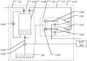
本公开至少一个实施例提供一种液化气体储能发电装置。图1为根据本公开一实施例提供一种液化气体储能发电装置的示意图。如图1所示,该液化气体储能发电装置包括气体压缩膨胀单元110、液化储能单元120、热电交换单元130以及液体源140。气体压缩膨胀单元110包括气体端口112;液化储能单元120与气体压缩膨胀单元110相连;热电交换单元130与液化储能单元120相连;液体源140与热电交换单元130相连,气体压缩膨胀单元110被配置为利用电能对来自气体端口112的气体进行压缩、膨胀以形成第一压缩气体并将第一压缩气体输送至液化储能单元120,热电交换单元130 被配置为利用电能吸收液化储能单元120中液态气体的热量并将热量转移至液体源140以促使第一压缩气体在液化储能单元120中液化,热电交换单元 130还被配置为利用液体源140与液化储能单元120中液态气体的温差进行发电并将液体源的热量转移至液化储能单元120中液态气体以促使液化储能单元120中液态气体气化,气体压缩膨胀单元110还被配置为利用液化储能单元120中的气体进行发电。At least one embodiment of the present disclosure provides a liquefied gas energy storage power generation device. FIG. 1 is a schematic diagram of a liquefied gas energy storage power generation device according to an embodiment of the present disclosure. As shown in FIG. 1 , the liquefied gas energy storage power generation device includes a gas compression and
在本实施例提供的液化气体储能发电装置中,在进行储能时,气体压缩膨胀单元110可消耗电能来压缩来自气体端口112的气体(例如,空气)以形成第一压缩气体(具有特定压强和温度的气体)并将第一压缩气体输送至液化储能单元120,热电交换单元130可消耗电能吸收液化储能单元120中液态气体的热量并将热量转移至液体源140以促使第一压缩气体在液化储能单元120中液化,从而将电能存储在液化气体中。由于液化气体的体积较小,存储的能量较高,因此该液化气体储能发电技术的存储容量比较大,而所占用的体积则相对较小。另一方面,液化气体无污染、对环境友好、成本较低,因此该液化气体储能发电装置具有无污染、对环境友好、储能成本较低、经济效益高等优点。当本实施例提供的液化气体储能发电装置进行发电时,热电交换单元130还被配置为利用液体源140与液化储能单元120中液态气体的温差进行发电并将液体源的热量转移至液化储能单元120中液态气体,促使液态气体汽化以使液化储能单元120中液态气体气化,气体压缩膨胀单元 110还被配置为利用液化储能单元120中的气体进行膨胀做功以进行发电。因此,该液化气体储能发电装置提供一种新型的利用液化空气进行储能发电的装置。并且,该液化气体储能发电装置的能量利用效率较高。需要说明的是,在本实施例提供的液化气体储能发电装置的运行过程中,液化储能单元 120内气液两相物质通过混合实现热交换,从而可使液化储能单元120内气液两相物质温度保持稳定。In the liquefied gas energy storage power generation device provided in this embodiment, during energy storage, the gas compression and
例如,在一些示例中,第一压缩气体处于气液临界状态。由此,当热电交换单元消耗电能吸收液化储能单元中液态气体的热量并将热量转移至液体源时,可便于将第一压缩气体在液化储能单元中液化。For example, in some examples, the first compressed gas is in a gas-liquid critical state. Thus, when the thermoelectric exchange unit consumes electrical energy to absorb the heat of the liquid gas in the liquefied energy storage unit and transfer the heat to the liquid source, it may be facilitated to liquefy the first compressed gas in the liquefied energy storage unit.
例如,在一些示例中,如图1所示,气体压缩膨胀单元110和热电交换单元130可连接到电网300。由此,该液化气体储能发电装置可在电网300 负荷较低的情况下将多余电能存储起来,在电网300负荷较高的情况下利用存储的能量进行发电以提高对能源的利用效率。For example, in some examples, as shown in FIG. 1 , the gas
图2为根据本公开一实施例提供一种液化气体储能发电装置的示意图。如图2所示,液化储能单元120包括相互连通的液体空间121和气体空间 122,液体空间121被配置为存储液化气体,气体空间122被配置为存储气体,气体压缩膨胀单元110与气体空间122相连,热电交换单元130与液体空间121相连。需要说明的是,上述的液体空间和气体空间是指液体或气体所占据的空间,另外,上述液体空间和气体空间的分界线可随着液体的增加、气体的减少或者液体的减少、气体的增加而变化,并非固定的空间。FIG. 2 is a schematic diagram of a liquefied gas energy storage power generation device according to an embodiment of the present disclosure. As shown in FIG. 2 , the liquefied
图3为根据本公开一实施例提供的一种气体压缩膨胀单元的示意图。如图3所示,气体压缩膨胀单元110包括至少一个压缩膨胀模块1100,各压缩膨胀模块1100包括等温压缩膨胀装置114,绝热压缩膨胀装置116和控温液体源150。等温压缩膨胀装置114分别与气体端口112和控温液体源150相连;绝热压缩膨胀装置116与等温压缩膨胀装置114相连,等温压缩膨胀装置116可利用电能和控温液体源150中的液体对来自气体端口112的气体进行等温压缩以形成第二压缩气体并输送至绝热压缩膨胀装置116,绝热压缩膨胀单元116可对第二压缩气体进行绝热膨胀以形成第三压缩气体,等温压缩膨胀装置114还可利用液化储能单元110中的气体进行发电。由此,控温液体源150中的液体使压缩膨胀单元110的气体的温度保持稳定,从而进行等温压缩,从而可进一步提高该液化气体储能发电装置的能量利用效率。需要说明的是,由于气体压缩膨胀单元110可包括多个压缩膨胀模块1100,因此,第三压缩气体与第一压缩气体的状态不同;当气体压缩膨胀单元仅包括一个压缩膨胀模块1100时,第三压缩气体与第一压缩气体的状态相同。FIG. 3 is a schematic diagram of a gas compression and expansion unit according to an embodiment of the present disclosure. As shown in FIG. 3 , the gas compression-
在本实施例提供的液化气体储能发电装置进行储能时,外部气体(例如空气)先通过气体端口112进入等温压缩膨胀装置114进行等温压缩,以形成第二压缩气体,即高压气体;第二压缩气体再通过气体管道进入绝热压缩膨胀装置116进行绝热膨胀,从而变成第三压缩气体;第三压缩气体通过气体管道转移至液化储能单元120,或者,当气体压缩膨胀单元110包括多个压缩膨胀模块1100时,第三压缩气体通过气体管道进入另一个压缩膨胀模块110,以继续进行压缩。在本实施例提供的液化气体储能发电装置进行发电时,液化储能单元120中的气态气体先通过气体管道进入绝热压缩膨胀装置116进行绝热压缩,以变为高温高压的气体,高温高压的气体再通过气体管道进入等温压缩膨胀装置114以进行等温膨胀并进行发电,等温膨胀后的气体经气体管道排出,或者,当气体压缩膨胀单元110包括多个压缩膨胀模块1100时,等温膨胀后的气体经气体管道转移至另一个压缩膨胀模块1100以继续进行发电。需要说明的是,经过绝热膨胀后,第三压缩气体的压强小于第二压缩气体的压强。When the liquefied gas energy storage power generation device provided in this embodiment performs energy storage, external gas (such as air) first enters the isothermal compression and
例如,当气体压缩膨胀单元110仅包括一个压缩膨胀模块1100时,第三压缩气体为第一压缩气体。For example, when the gas compression and
例如,在一些示例中,绝热压缩膨胀装置116出口设置节流阀,在本实施例提供的液化气体储能发电装置进行储能时,第三压缩气体经节流阀节流液化进入液化储能单元120进一步促进气体液化的进行。For example, in some examples, a throttle valve is set at the outlet of the adiabatic compression-
图4为根据本公开一实施例提供的另一种气体压缩膨胀单元的示意图。如图4所示,各压缩膨胀模块1100还包括第一活塞杆115和第一发电设备 117。等温压缩膨胀装置114和绝热压缩膨胀装置116均通过第一活塞杆115 与第一发电设备117相连,第一发电设备117连接电网300。当本示例提供的液化气体储能发电装置进行储能时,外部气体先通过气体端口112进入等温压缩膨胀装置114进行等温压缩,从而变为第二压缩气体,即高压气体;第二压缩气体再通过气体管道进入绝热压缩膨胀装置116进行绝热膨胀,从而变为第三压缩气体;最后,第三压缩气体通过气体管道转移至液化储能单元120或下一个压缩膨胀模块1100。当本示例提供的液化气体储能发电装置进行发电时,液化储能单元120中的气态气体先通过气体管道进入绝热压缩膨胀装置116进行绝热压缩,从而变为高温高压的气体,高温高压的气体再通过气体管道进入等温压缩膨胀装置114进行等温膨胀,从而进行发电;经过等温膨胀的气体通过气体端口112排出或转移至另一个压缩膨胀模块以继续进行发电。FIG. 4 is a schematic diagram of another gas compression and expansion unit provided according to an embodiment of the present disclosure. As shown in FIG. 4 , each
例如,在一些示例中,第一发电设备117可为直线发电机、曲柄发电机、以液压机构为基础的虚拟抽蓄系统或液压泵系统。For example, in some examples, the first
例如,在一些示例中,如图4所示,等温压缩膨胀装置114和绝热压缩膨胀装置116通过第一活塞杆115同轴相连,当然,本公开包括但不限于此,等温压缩膨胀装置114和绝热压缩膨胀装置116也可分别与单独的活塞杆相连。For example, in some examples, as shown in FIG. 4 , the isothermal compression-
图5为根据本公开一实施例提供的另一种气体压缩膨胀单元的示意图。如图5所示,气体压缩膨胀单元110包括至少一个压缩膨胀模块1100。压缩膨胀模块1100包括气体端口112、等温压缩膨胀装置114以及绝热压缩膨胀装置116。等温压缩膨胀装置114和绝热压缩膨胀装置116均连接电网300,等温压缩膨胀装置114以及绝热压缩膨胀装置116可通过气体管道相连。FIG. 5 is a schematic diagram of another gas compression and expansion unit provided according to an embodiment of the present disclosure. As shown in FIG. 5 , the gas
例如,在一些示例中,如图5所示,等温压缩膨胀装置114可通过控温液体活塞1140实现等温压缩和等温膨胀过程。例如,等温压缩膨胀装置114 包括控温液体活塞1140、设置在气体端口112上的阀门1-1、设置在第一气体管道113上的阀门1-2、设置在液体管道1141上的阀门1-4、第二发电设备1142、以及第一电机1143。控温液体活塞1140通过阀门1-1连接气体端口112,通过阀门1-2连接第一气体管道113;控温液体活塞1140通过液体管道1141与控温液体源150相连,并通过阀门1-4连接第二发电设备1142;第一电机1143连接控温液体活塞1140的上下两端,通过循环抽水来促进温液体活塞1140中的气水混合;第二发电设备1142连接电网300。当然,本公开包括但不限于此,等温压缩膨胀装置也可采用其他方式来实现等温压缩和等温膨胀过程。例如,等温压缩膨胀装置可采用螺杆空压机、喷淋式等温压缩膨胀装置或多级压缩中间换热装置来实现等温压缩和等温膨胀过程。For example, in some examples, as shown in FIG. 5 , the isothermal
例如,在一些示例中,第二发电设备1142可为直线发电机、曲柄发电机、以液压机构为基础的虚拟抽蓄系统或液压泵系统。For example, in some examples, the second
例如,在一些示例中,如图5所示,所述绝热压缩膨胀装置包括压缩机 1161,压缩机1161被配置为利用电能压缩来自液化储能单元120中的气体以形成第四压缩气体,等温压缩膨胀装置114还可利用第四压缩气体进行发电,第四压缩气体的压强大于第一压缩气体。由此,可提高发电效率。For example, in some examples, as shown in FIG. 5, the adiabatic compression-expansion device includes a
例如,在一些示例中,如图5所示,绝热压缩膨胀装置116可通过压缩机1161和膨胀机1162来实现绝热压缩和绝热膨胀过程。例如,绝热压缩膨胀装置116包括膨胀机1161、压缩机1162、阀门3-1、阀门3-2、阀门3-3、阀门3-4以及第三发电设备1163。第一气体管道113通过阀门3-1和阀门3-2 分别连接膨胀机1161和压缩机1162;压缩机1161和膨胀机1162分别通过阀门3-3和阀门3-4与外界相连(例如,液化储能单元或者下一个压缩膨胀模块);膨胀机1161和压缩机1162分别通过第二活塞杆1164和第三活塞杆 1165与第三发电设备1163相连;第三发电设备1163可连接电网300。例如,第三发电设备1163可包括电机和发电机,以利用电能做功以及利用机械能发电。For example, in some examples, as shown in FIG. 5 , adiabatic compression-
例如,在一些示例中,第三发电设备1163可为直线发电机、曲柄发电机、以液压机构为基础的虚拟抽蓄系统或液压泵系统。For example, in some examples, the third
图5示出的气体压缩膨胀单元在初始状态时,所有阀门全关闭,控温液体活塞1140注入部分控温液体源150中的液体。当本示例提供的液化气体储能发电系统进行储能时,先打开阀门1-1,外部气体(例如空气)先通过气体端口112进入控温液体活塞1140,关闭阀门1-1;打开阀门1-4,第二发电设备1142作为水泵运行,利用电能将控温液体源150中液体转移至控温液体活塞1140将控温液体活塞1140内的气体等温压缩变为高压气体,例如,将来自气体端口112的气体进行等温压缩以形成第二压缩气体,第一电机1143在压缩过程中一直运行使控温液体活塞1140内气水充分混合促进等温压缩;压缩完成后,打开阀门1-2、3-1、3-3,由于控温液体源150中的液体被持续转移至控温液体活塞1140,控温液体活塞1140内高压气体(例如,第二压缩气体)将通过第一气体管道113等压迁移进入膨胀机1161,经过绝热膨胀变为特定温度和压强的气体并通过第二活塞杆1164推动第三发电设备1163发电,例如,将所述第二压缩气体进行膨胀以形成第三压缩气体,最后将获得的气体转移至液化储能单元120或另一个压缩膨胀模块。在气体等温压缩过程,第二发电设备1142消耗电能,在气体绝热膨胀过程中,第三发电设备1163发出电能,整体上将消耗电能。In the initial state of the gas compression and expansion unit shown in FIG. 5 , all valves are fully closed, and the temperature-controlling
当本示例提供的液化气体储能发电系统进行发电时,打开阀门1-2、1-4、 3-2、3-4,液化储能单元120中的气态气体或上一个压缩膨胀模块中的气体进入压缩机1162,以进行绝热压缩变为第四压缩气体,即高温高压的气体;高温高压的气体再通过第一气体管道113进入控温液体活塞1140;关闭阀门 1-2,高温高压的气体在控温液体活塞1140中进行等温膨胀,从而推动第二发电设备1142发电。同样地,第一电机1143可在压缩过程中一直运行使控温液体活塞1140内气水充分混合促进等温压缩;气体发电后,打开阀门1-1,气体经气体端口112排出或转移至下一个压缩膨胀模块。在气体绝热压缩过程中,第三发电设备1163消耗电能,在气体等温膨胀过程中,第二发电设备1142发出电能,整体上将发出电能。When the liquefied gas energy storage power generation system provided in this example generates electricity, open the valves 1-2, 1-4, 3-2, 3-4 to liquefy the gaseous gas in the
例如,在一些示例中,等温压缩膨胀装置可通过螺杆式空压机来实现等温压缩和等温膨胀。该等温压缩膨胀装置包括:螺杆式空压机;储气装置;第二气体管道;以及发电设备,储气装置分别连接第二气体管道和第一气体管道;第二气体管道连接储气装置和螺杆式空压机;螺杆式空压机与气体端口相连,螺杆式空压机还与发电设备相连,绝热压缩膨胀装置还包括:控温液压活塞,控温液压活塞与螺杆式空压机和发电设备相连。For example, in some examples, the isothermal compression expansion device can achieve isothermal compression and isothermal expansion by means of a screw air compressor. The isothermal compression and expansion device comprises: a screw-type air compressor; a gas storage device; a second gas pipeline; Screw-type air compressor; the screw-type air compressor is connected with the gas port, the screw-type air compressor is also connected with the power generation equipment, and the adiabatic compression and expansion device also includes: temperature-controlled hydraulic piston, temperature-controlled hydraulic piston and screw-type air compressor and connected to power generation equipment.
图6为根据本公开一实施例提供的另一种气体压缩膨胀单元的示意图。如图6所示,气体压缩膨胀单元110包括至少一个压缩膨胀模块1100。压缩膨胀模块1100包括气体端口112、第一气体管道113、等温压缩膨胀装置114、绝热压缩膨胀装置116、第四发电设备1144、第四活塞杆1145。等温压缩膨胀装置114通过气体端口112与外界或另一个压缩膨胀模组相连,通过第一气体管道113与绝热压缩膨胀装置116相连。绝热压缩膨胀装置116可连接液化储能单元120或下一个压缩膨胀模块。等温压缩膨胀装置114和绝热压缩膨胀装置116均通过第四活塞杆1145与第四发电设备1144相连。第四发电设备1144可连接电网300。FIG. 6 is a schematic diagram of another gas compression and expansion unit provided according to an embodiment of the present disclosure. As shown in FIG. 6 , the gas
例如,如图6所示,等温压缩膨胀装置114可通过螺杆式空压机1146、储气装置1147和第二气体管道1148实现等温压缩过程。储气装置1147分别通过阀门1-9、阀门1-10连接第二气体管道1148和第一气体管道113;第二气体管道1148连接储气装置1147和螺杆式空压机1146;螺杆式空压机 1146通过阀门1-6与气体端口112相连;因此储气装置1147通过阀门1-9、螺杆式空压机1146、阀门1-6与气体端口112相连。螺杆式空压机1146还通过第四活塞杆1145连接第四发电设备1144。绝热压缩膨胀装置116包括液压活塞1160,从而可通过液压活塞1160实现绝热压缩膨胀。绝热压缩膨胀装置116包括阀门3-14、阀门3-15、阀门3-16和阀门3-17。液压活塞1160 通过第四活塞杆1145与螺杆式空压机1146和第四发电设备1144相连。液压活塞1160与通过阀门3-14和阀门3-15连接第一气体管道113,通过阀门 3-16和阀门3-17与外界或另一个压缩膨胀模块相连。For example, as shown in FIG. 6 , the isothermal compression and
例如,在一些示例中,第四发电设备1144可为直线发电机、曲柄发电机、以液压机构为基础的虚拟抽蓄系统或液压泵系统。For example, in some examples, the fourth
图6示出的气体压缩膨胀单元在初始状态时,所有阀门全关闭。当本示例提供的液化气体储能发电系统进行储能时,先打开阀门1-6,外部气体先通过气体端口112进入螺杆式空压机1146,同时第二电机1149将控温液体源115的液体转移至螺杆式空压机1146;第四发电设备1144作电动机运行推动第四活塞杆1145将螺杆式空压机1146内气液混合物进行等温压缩,变为高压气液混合物;打开阀门1-9,高压气液混合物通过第二气体管道1148 进入储气装置1147;压缩完成后,关闭阀门1-9,打开阀门1-10、阀门3-15,储气装置1147内高压气体将通过第一气体管道113等压迁移进入液压活塞1160中,关闭阀门3-15;高压气体在液压活塞1160中绝热膨胀变为特定温度和压强的气体并推动第四活塞杆1145,此时第四发电设备1144作发电机进行发电;最后打开阀门3-14和阀门3-17,高压气体进入液压活塞1160,同时,特定温度和压强的气体转移至液化储能单元120或另一个压缩膨胀模块;之后,关闭阀门3-14,准备下一次绝热膨胀。在本示例提供的液化气体储能发电系统进行储能的整个过程中,阀门1-12和第四发电设备1144通过相互配合维持储气装置1147内压强的稳定。另外,在本示例提供的液化气体储能发电系统进行储能的整个过程中,与第四活塞杆1145同轴相连的螺杆式空压机1146和液压活塞1160可以使气体等温压缩过程和绝热膨胀过程同时进行,从而可提高运行效率。在气体等温压缩过程,第四发电设备1144 消耗电能,在气体绝热膨胀过程中,第四发电设备1144发出电能,整体上将消耗电能。In the initial state of the gas compression and expansion unit shown in FIG. 6 , all valves are fully closed. When the liquefied gas energy storage power generation system provided in this example performs energy storage, the valves 1-6 are opened first, and the external air first enters the
例如,在一些示例中,等温压缩膨胀装置包括:至少两级压缩膨胀装置;以及换热装置,与各两级压缩膨胀装置相连,各压缩膨胀装置包括膨胀机和压缩机并被配置为实现绝热压缩和绝热膨胀,换热装置被配置为恢复经对应设置的压缩膨胀装置绝热压缩或绝热膨胀之后的气体的温度。For example, in some examples, an isothermal compression-expansion device includes: at least two-stage compression-expansion devices; and a heat exchange device coupled to each of the two-stage compression-expansion devices, each of the compression-expansion devices including an expander and a compressor and configured to achieve thermal insulation Compression and adiabatic expansion, the heat exchange device is configured to restore the temperature of the gas after adiabatic compression or adiabatic expansion of the correspondingly arranged compression and expansion device.
图7为根据本公开一实施例提供的一种气体压缩膨胀单元中等温压缩膨胀装置的示意图。等温压缩膨胀装置114可通过多级压缩膨胀、中间换热的方式以实现等温压缩膨胀。图7示出了一种两级压缩膨胀,中间换热的等温压缩膨胀装置。如图7所示,等温压缩膨胀装置114包括阀门1-15、阀门1-16、阀门1-19、阀门1-20、压缩机1-18、膨胀机1-17、发电设备1-21、换热器 1-22、电机1-23、阀门1-24、阀门1-25、阀门1-28、阀门1-29、压缩机1-27、膨胀机1-16、发电设备1-30、换热器1-31、电机1-32。气体端口112分别通过阀门1-15、阀门1-16连接膨胀机1-17、压缩机1-18,换热器1-22分别通过阀门1-19、阀门1-20连接膨胀机1-17、压缩机1-18,发电设备1-21分别通过活塞杆连接膨胀机1-17、压缩机1-18;换热器1-22分别通过阀门1-24、阀门1-25连接膨胀机1-26、压缩机1-27,换热器1-31分别通过阀门1-28、阀门1-29连接膨胀机1-26、压缩机1-27,发电设备1-30分别通过活塞杆连接膨胀机1-26、压缩机1-27,换热器1-31连接第一气体管道113;发电设备 1-21、发电设备1-30连接电网,换热器1-22、换热器1-31分别通过电机1-23、阀门1-32与外部液体管道相连,从而与控温液体源相连。7 is a schematic diagram of an isothermal compression and expansion device for a gas compression and expansion unit provided according to an embodiment of the present disclosure. The isothermal compression-
图7示出的气体压缩膨胀单元在初始状态时,所有阀门全关闭。当本示例提供的液化气体储能发电系统进行储能时,打开阀门1-16、阀门1-20、阀门1-25、阀门1-29,外部气体先通过气体端口112进入压缩机1-17绝热压缩升温升压;气体绝热压缩后进入换热器1-22与控温液体源中的液体换热恢复至最初的温度后进入压缩机1-27;气体在压缩机1-27中再次绝热压缩升温升压;气体绝热压缩后进入再次进入换热器1-31与控温液体换热恢复至最初的温度后进入第一气体管道113。在本示例提供的液化气体储能发电系统进行储能的整个过程中,电机1-23、电机1-32不断通过外部液体管道将控温液体源中的液体转移至换热器1-22、换热器1-31与气体换热;整个过程为近似的等温压缩过程,分级数越多,整个过程越接近等温。In the initial state of the gas compression and expansion unit shown in FIG. 7 , all valves are fully closed. When the liquefied gas energy storage power generation system provided in this example performs energy storage, open the valve 1-16, valve 1-20, valve 1-25, and valve 1-29, and the external gas first enters the compressor 1-17 through the
当本示例提供的液化气体储能发电系统进行发电时,打开阀门1-28、 1-24、1-19、1-15,气体先通过第一气体管道113进入膨胀机1-26绝热膨胀降温降压;气体绝热膨胀后进入换热器1-22与控温液体换热恢复至最初的温度后进入膨胀机1-17;气体在压缩机1-17中再次绝热压缩降温降压;气体绝热膨胀后进入再次进入换热器1-34与控温液体换热恢复至最初的温度后进入气体端口112;在本示例提供的液化气体储能发电系统进行储能的整个过程中,电机1-23、1-33不断通过将控温液体转移至换热器1-22、1-34 与气体换热;整个过程为近似的等温膨胀过程,分级数越多,整个过程越接近等温。When the liquefied gas energy storage power generation system provided in this example is generating electricity, the valves 1-28, 1-24, 1-19, 1-15 are opened, and the gas first enters the expander 1-26 through the
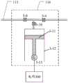
图8为根据本公开一实施例提供的一种气体压缩膨胀单元中的绝热压缩膨胀装置的示意图。绝热压缩膨胀装置116可通过液压活塞实现绝热压缩膨胀。如图8所示,绝热压缩膨胀装置116包括阀门3-8、阀门3-9、阀门3-10、活塞杆3-11、活塞缸3-12、发电设备3-13。第一气体管道130通过阀门3-8、阀门3-10连接活塞缸3-12;活塞缸3-12通过阀门3-9、阀门3-10与外界或另一个压缩膨胀模块相连;发电设备3-13通过活塞杆3-11连接活塞缸3-12,发电设备3-13连接电网。8 is a schematic diagram of an adiabatic compression-expansion device in a gas compression-expansion unit provided according to an embodiment of the present disclosure. The adiabatic compression-
图8示出的气体压缩膨胀单元在初始状态时,所有阀门全关闭。当本示例提供的液化气体储能发电系统进行储能时,打开阀门3-8、阀门3-10,气体先通过第一气体管道113进入活塞缸3-12,关闭阀门3-8;气体在活塞缸 3-12中绝热膨胀推动活塞杆3-11使发电设备3-13发出电能;气体降至指定温度和压强后,打开阀门3-9,气体进入液化储能单元120或另一个压缩膨胀模块。In the initial state of the gas compression and expansion unit shown in FIG. 8 , all valves are fully closed. When the liquefied gas energy storage power generation system provided in this example performs energy storage, the valve 3-8 and valve 3-10 are opened, the gas first enters the piston cylinder 3-12 through the
当本示例提供的液化气体储能发电系统进行发电时,打开阀门3-9、阀门3-10,气体先进入活塞缸3-12,关闭阀门3-9;发电设备3-13消耗电能推动活塞杆3-11使气体在活塞缸3-12中绝热压缩;气体压缩至指定压强和温度后,打开阀门3-8,气体通过第一气体管道113进入等温压缩膨胀装置。When the liquefied gas energy storage power generation system provided in this example is generating electricity, open the valves 3-9 and 3-10, the gas first enters the piston cylinder 3-12, and close the valve 3-9; the power generation equipment 3-13 consumes electricity to push the piston The rod 3-11 compresses the gas adiabatically in the piston cylinder 3-12; after the gas is compressed to the specified pressure and temperature, the valve 3-8 is opened, and the gas enters the isothermal compression and expansion device through the
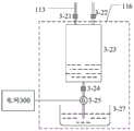
图9为根据本公开一实施例提供的另一种气体压缩膨胀单元中的绝热压缩膨胀装置的示意图。绝热压缩膨胀装置可通过液体活塞实现绝热压缩膨胀。如图9所示,绝热压缩膨胀装置116包括阀门3-21、阀门3-22、液体活塞3-23、阀门3-24、液体管道3-26、液体源3-27、发电设备3-25。液体活塞分别通过阀门3-21连接第一气体管道113,通过阀门3-22与外界相连;液体活塞3-23通过阀门3-24连接发电设备3-25和液体管道3-26,液体管道 3-26连接液体源3-27;发电设备3-25连接电网300。9 is a schematic diagram of an adiabatic compression-expansion device in another gas compression-expansion unit provided according to an embodiment of the present disclosure. The adiabatic compression-expansion device can achieve adiabatic compression-expansion through a liquid piston. As shown in FIG. 9 , the adiabatic
图9示出的气体压缩膨胀单元在初始状态时,所有阀门全关闭。当本示例提供的液化气体储能发电系统进行储能时,打开阀门3-21,气体先通过第一气体管道113进入液体活塞3-23,关闭阀门3-21;打开阀门3-24,气体在液体活塞3-23中绝热膨胀,液体活塞3-23中的液体推动发电设备3-25进行发电,液体排出至液体源3-27;气体降至指定温度和压强后,关闭阀门3-24,打开阀门3-22,气体进入液化储能单元120或另一个压缩膨胀模块。In the initial state of the gas compression and expansion unit shown in FIG. 9 , all valves are fully closed. When the liquefied gas energy storage power generation system provided in this example performs energy storage, open the valve 3-21, the gas first enters the liquid piston 3-23 through the
当本示例提供的液化气体储能发电系统进行发电时,打开阀门3-22,气体先进入液体活塞3-23,关闭阀门3-22;打开阀门3-24,发电设备3-25消耗电能将液体源3-27内液体转移至液体活塞3-23使气体在液体活塞3-23中绝热压缩;气体压缩至指定压强和温度后,关闭阀门3-24,打开阀门3-21,气体通过第一气体管道113进入等温压缩膨胀装置。When the liquefied gas energy storage power generation system provided in this example generates electricity, open the valve 3-22, the gas first enters the liquid piston 3-23, close the valve 3-22; open the valve 3-24, the power consumption of the power generation equipment 3-25 will be The liquid in the liquid source 3-27 is transferred to the liquid piston 3-23, and the gas is compressed adiabatically in the liquid piston 3-23; after the gas is compressed to the specified pressure and temperature, the valve 3-24 is closed, and the valve 3-21 is opened, and the gas passes through the
图10为本公开一实施例提供的一种液化气体储能发电装置的热电交换单元的示意图。如图10所示,该热电交换单元130包括第一气体等温压缩膨胀装置1301、第二气体等温压缩膨胀装置1302和两个绝热压缩膨胀装置 1303。第一气体等温压缩膨胀装置1301被配置为对第一气体进行等温压缩、膨胀;第二气体等温压缩膨胀装置1302被配置为对第二气体进行等温压缩、膨胀;绝热压缩膨胀装置1303被配置为分别对第一气体和第二气体进行绝热压缩、膨胀,实现第一气体和第二气体的交换。10 is a schematic diagram of a thermoelectric exchange unit of a liquefied gas energy storage power generation device according to an embodiment of the disclosure. As shown in FIG. 10 , the
例如,当采用图10所示的热电交换单元的液化气体储能发电系统在进行储能时,假设初始状态时,第一气体为低温高压气体,第一气体等温压缩膨胀装置的控温液体源为低温液体;第二气体为高温低压气体,第二气体等温压缩膨胀装置的控温液体源为高温液体。热电交换单元利用电能使第二气体在第二气体等温压缩膨胀装置等温压缩变为高温高压的气体,同时使第一气体在第一气体等温压缩膨胀装置等温膨胀变为低温低压的气体;高温高压的第二气体经绝热压缩膨胀设备绝热膨胀变为高压低温的第一气体送入第一气体等温压缩膨胀装置,同时低温低压的第一气体经另一绝热压缩膨胀设备绝热压缩变为低压高温的第二气体送入第二气体等温压缩膨胀装置。热电交换单元消耗电能将第一气体等温压缩膨胀装置的低温的控温液体源的热量转移至第二气体等温压缩膨胀装置的高温的控温液体源。For example, when the liquefied gas energy storage power generation system using the thermoelectric exchange unit shown in FIG. 10 is performing energy storage, it is assumed that in the initial state, the first gas is a low-temperature high-pressure gas, and the temperature-controlled liquid source of the isothermal compression and expansion device for the first gas is It is a low temperature liquid; the second gas is a high temperature and low pressure gas, and the temperature control liquid source of the second gas isothermal compression and expansion device is a high temperature liquid. The thermoelectric exchange unit utilizes electric energy to make the second gas isothermally compressed in the second gas isothermal compression and expansion device to become a high-temperature and high-pressure gas, and at the same time, the first gas is isothermally expanded in the first gas isothermal compression-expansion device to become a low-temperature and low-pressure gas; high-temperature and high-pressure gas; The second gas is adiabatically expanded into a high-pressure and low-temperature first gas through adiabatic compression-expansion equipment, and is sent to the first gas isothermal compression-expansion device. The second gas is fed into the second gas isothermal compression and expansion device. The thermoelectric exchange unit consumes electric energy to transfer the heat of the low temperature temperature-controlled liquid source of the first gas isothermal compression expansion device to the high temperature temperature controlled liquid source of the second gas isothermal compression expansion device.
当采用图10所示的热电交换单元的液化气体储能发电系统在进行发电时,假设初始状态时,第一气体为低温低压气体,第一气体等温压缩膨胀装置的控温液体源为低温液体;第二气体为高温高压气体,第二气体等温压缩膨胀装置的控温液体源为高温液体。第二气体在第二气体等温压缩膨胀装置等温膨胀变为高温低压的气体,同时使第一气体在第一气体等温压缩膨胀装置等温压缩变为低温高压的气体;高温低压的第二气体经绝热压缩膨胀设备绝热膨胀变为低压低温的第一气体送入第一气体等温压缩膨胀装置,同时低温低压的第一气体经另一绝热压缩膨胀设备绝热压缩变为高压高温的第二气体送入第二气体等温压缩膨胀装置。第二气体等温压缩膨胀装置的高温的控温液体源的热量转移至第一气体等温压缩膨胀装置的低温温的控温液体源,热电交换单元发出电能。When the liquefied gas energy storage power generation system using the thermoelectric exchange unit shown in FIG. 10 is generating electricity, assuming the initial state, the first gas is a low-temperature and low-pressure gas, and the temperature-controlling liquid source of the first gas isothermal compression and expansion device is a low-temperature liquid. The second gas is high temperature and high pressure gas, and the temperature control liquid source of the second gas isothermal compression and expansion device is high temperature liquid. The second gas is isothermally expanded in the second gas isothermal compression expansion device to become a high temperature and low pressure gas, while the first gas is isothermally compressed in the first gas isothermal compression expansion device to become a low temperature and high pressure gas; the high temperature and low pressure second gas is adiabatic The first gas with low pressure and low temperature after adiabatic expansion by compression and expansion equipment is sent to the first gas isothermal compression and expansion device. Two gas isothermal compression expansion device. The heat of the high temperature temperature control liquid source of the second gas isothermal compression expansion device is transferred to the low temperature temperature control liquid source of the first gas isothermal compression expansion device, and the thermoelectric exchange unit generates electric energy.
需要说明的是,第一外部液体源310内的液体的温度可大于第二外部液体源320内液体的温度。It should be noted that the temperature of the liquid in the first external
例如,在一些示例中,第一气体和第二气体可以同时采用氢气或氦气,第一气体和第二气体也可以分别同时采用氢气和氦气。For example, in some examples, the first gas and the second gas may be hydrogen or helium, and the first gas and the second gas may be hydrogen and helium, respectively.
图11为本公开一实施例提供的另一种热电交换单元的示意图。如图11 所示,该热电交换单元130包括至少一个热电交换模块1300,各热电交换模块1300包括第一压力罐134,可存储第一温度范围的液体和第一气体;第二压力罐136,可存储第二温度范围的液体和第二气体;液压控制机构1310,包括第一液压活塞137;第二液压活塞139;换气机构138,与第一压力罐 134和第二压力罐136相连,并可交换第一气体和第二气体;以及发电设备135。第一压力罐134与第一液压活塞137相连,第二压力罐136与第二液压活塞139相连,第一液压活塞137、第二液压活塞139、发电设备135机械相连,例如,通过活塞杆同轴相连。初始状态时,假设第一气体为高压气体,第一液压活塞137可在第一气体的膨胀作用下运动,发电设备135被第一液压活塞137驱动,第二液压活塞139推动第二温度范围的液体进入第二压力罐136并压缩第二气体。当第二气体转变为高压气体时,第二液压活塞 133可在第二气体的膨胀作用下运动,发电设备135被第二液压活塞139驱动,第一液压活塞137推动第一温度范围的液体进入第一压力罐136并压缩第一气体。由此,该热电交换模块可利用第一温度范围的液体和第二温度范围的液体的温度差进行发电。FIG. 11 is a schematic diagram of another thermoelectric exchange unit provided by an embodiment of the disclosure. As shown in FIG. 11 , the
例如,如图11所示,该热电交换模块1300包括第一压力罐第一压力罐 134、发电设备135、第二压力罐136、换气机构138。该换气机构138通过液压活塞实现,包括阀门8-1、阀门8-2、阀门8-3、液压活塞缸8-6、活塞杆8-5、发电设备8-4。液压活塞缸8-6通过阀门8-3、8-1连接第一压力罐 134;液压活塞缸8-6通过阀门8-3、8-2连接第二压力罐136;液压活塞缸8-6通过活塞杆8-5连接发电设备8-4。该热电交换模块还包括第一液压活塞 137、第二液压活塞139、阀门9-1、阀门9-2、阀门9-3、阀门9-4、阀门9-5、阀门9-6、阀门9-7和阀门9-8。液压第一液压活塞137通过阀门9-1、9-2连接第一压力罐134;液压第一液压活塞137通过阀门9-3、9-4连接第一外部液体源310;液压第二液压活塞139通过阀门9-5、9-6连接第二压力罐136;液压第一液压活塞137通过阀门9-7、9-8连接第二外部液体源320;发电设备135通过活塞杆连接第一液压活塞137和第二液压活塞139;发电设备135 可连接电网300。For example, as shown in FIG. 11 , the
需要说明的是,第一外部液体源310内的液体的温度可小于第二外部液体源320内液体的温度;发电设备135也可为直线发电机或曲柄发电机或以液压机构为基础的虚拟抽蓄系统或液压泵系统;第一液压活塞137和第二液压活塞139可通过活塞杆同轴相连或分别与单独的活塞杆相连。It should be noted that the temperature of the liquid in the first external
图11所示的热电交换模块处于初始状态时,所有阀门全关闭。When the thermoelectric exchange module shown in Fig. 11 is in the initial state, all valves are fully closed.
当采用图11所示的热电交换模块的的液化气体储能发电系统在进行储能时,假设初始时第一液压活塞137的活塞杆9-16位于第一液压活塞137 最左侧(其他位置类似),打开阀门9-1、9-4、9-6、9-7,第一压力罐134中的低温低压气体等温膨胀,第一温度范围的液体从第一压力罐134中流出,并经阀门9-1进入第一液压活塞137第一液压活塞137的左侧,第一液压活塞137右侧的第一温度范围的液体经阀门9-4进入第一外部液体源310,活塞杆9-16在第一温度范围的液体的推动下向右运动,同时,活塞杆9-16在第二液压活塞139中向右运动,第二液压活塞139右侧的第二温度范围的液体经阀门9-6进入第二压力罐136,第二温度范围的液体进入第二压力罐 136,压缩第二压力罐136内的第二气体,第二温度范围的液体经阀门9-7 进入第二液压活塞139的左侧,如此,活塞杆9-16运动到第一液压活塞137的最右侧。关闭阀门9-1、9-4、9-6、9-7,打开阀门9-2、9-3、9-5、9-8,第一压力罐134中的第一气体等温膨胀,第一温度范围的液体从第一压力罐 134中流出经阀门9-2进入第一液压活塞137的右侧,第一液压活塞137的左侧的第一温度范围的液体经阀门9-3进入第一外部液体源310,活塞杆9-16 在上述过程中被第一温度范围的液体推动,并向左运动,同时,活塞杆9-16 在第二液压活塞139中向左运动,推动活塞缸9-16左侧的第二温度范围的液体经阀门9-5进入第二压力罐136中,第二温度范围的液体进入第二压力罐6,压缩第二压力罐6内的第二气体,第二温度范围的液体经阀门9-8进入第二液压活塞139的右侧,这样直到活塞杆9-16运动到第一液压活塞137 的最左侧,再关闭阀门9-2、9-3、9-5、9-8,打开阀门9-1、9-4、9-6、9-7,如此往复,从而实现活塞杆9-16在第一液压活塞137和第二液压活塞139 内往复运动,并通过发电设备135消耗电能,实现热量由低温热源向高温热源的转移。当上述过程结束后,需要将第一压力罐134内气体送入第二压力罐136,第二压力罐136内的气体送入第一压力罐134。首先,可将第一压力罐134内的等温膨胀后的气体通过阀门8-1、8-3迁移至液压活塞缸8-6内,例如,可通过将发电设备135运行在电机模式以驱动活塞杆9-16在第一液压活塞137和第二液压活塞139中往复运动,消耗电网中的电能驱动活塞杆 9-16运动。由此,发电设备135可以驱动活塞杆9-16进行往复运动,当活塞杆9-16向右运动时,打开阀门9-2、9-3、8-1、8-3,关闭阀门9-1、9-4,同时将第二液压活塞139屏蔽,即打开阀门9-7、9-8,关闭阀门9-5、9-6,保证第二液压活塞139左右两侧都与第二外部液体源320相连,这样第一液压活塞139左右两侧压力相同,对活塞杆9-16的运动没有影响,同时也不改变第二压力罐136内的气体状态。开闭相关阀门后,第一温度范围的液体经阀门9-3进入第一液压活塞137的左侧,第一液压活塞137右侧的低温液体在活塞杆9-16的推动下经阀门9-2进入第一压力罐134内,第一压力罐 134内的气体通过阀门8-1、8-3进入液压活塞8-6内。当活塞杆9-16向左运动时,打开阀门9-1、9-4、8-1、8-3,关闭阀门9-2、9-3,同时打开阀门9-7、 9-8,关闭阀门9-5、9-6,将第二液压活塞139屏蔽,第一温度范围的液体经阀门9-4进入第一液压活塞137的右侧,第一液压活塞137左侧的第一温度范围的液体经阀门9-1进入第一压力罐134内,第一压力罐134内的气体通过阀门8-1、8-3进入液压活塞8-6内。如此,活塞杆9-16往复运动直到第一压力罐134内的气体全部进入液压活塞8-6内,此时,需要将第一压力罐 136内的气体迁移到第一压力罐134内,关闭阀门8-3,打开阀门8-1、8-2,当活塞杆9-16向右运动时,打开阀门9-1、9-4、9-6、9-7,关闭阀门9-2、 9-3、9-5、9-8,第二温度范围的液体经阀门9-7进入第二液压活塞139的左侧,第二液压活塞139右侧的第二温度范围的液体被活塞杆9-16推动经阀门9-6进入第一压力罐136内,第一压力罐136内的气体经阀门8-1、8-3进入第一压力罐134内,第一压力罐134内的第一温度范围的液体经阀门9-1 进入第一液压活塞137的左侧,第一液压活塞137右侧的第一温度范围的液体经阀门9-4进入第一外部液体源310内。当活塞杆9-16向左运动时,打开阀门9-2、9-3、9-5、9-8,关闭阀门9-1、9-4、9-6、9-7,第二外部液体源 320内的第二温度范围的液体经阀门9-8进入第二液压活塞139的右侧,第二液压活塞139左侧的第一温度范围的液体被活塞9-16推动经阀门9-5进入第一压力罐6内,第一压力罐6内的气体经过阀门8-1、8-3进入第一压力罐 134内,第一压力罐134内的第一温度范围的液体经阀门9-2进入第一液压活塞137的右侧,第一液压活塞137左侧的低温液体被活塞9-16推动经阀门9-3进入第一外部液体源310。如此,活塞杆9-16往复运动,直到第一压力罐6内的气体全部迁移到第一压力罐134内,此时需要将液压活塞8-6内的气体迁移至第一压力罐136内,关闭阀门8-1,打开阀门8-2、8-3,同时关闭阀门9-1、9-2,打开阀门9-3、9-4,将第一液压活塞137屏蔽,当活塞杆9-16向右运动时,打开阀门9-5、9-8,关闭阀门9-6、9-7,第二液压活塞 139右侧的第二温度范围的液体被活塞杆9-16推动经阀门9-8进入第二外部液体源320,第一压力罐136内的第二温度范围的液体经阀门9-5进入第二液压活塞139的左侧,液压活塞8-6内的气体经阀门8-2、8-3进入第一压力罐136内,当活塞杆9-16向左运动时,打开阀门9-6、9-7,关闭阀门9-5、 9-8,第二液压活塞139的左侧的第二温度范围的液体被活塞杆9-16推动经阀门9-7进入第二外部液体源320内,第二压力罐136内的第二温度范围的液体经阀门9-6进入第二液压活塞139的右侧,液压活塞8-6内的气体经阀门8-2、8-3进入第二压力罐136内。如此,活塞杆9-16往复运动直到液压活塞8-6内的气体全部迁移到第二压力罐136内,至此,气体中转迁移过程结束。When the liquefied gas energy storage power generation system using the thermoelectric exchange module shown in FIG. 11 performs energy storage, it is assumed that the piston rods 9-16 of the first hydraulic piston 137 are initially located at the leftmost position of the first hydraulic piston 137 (other positions similar), open the valves 9-1, 9-4, 9-6, 9-7, the low-temperature and low-pressure gas in the first pressure tank 134 expands isothermally, the liquid in the first temperature range flows out from the first pressure tank 134, and Enter the first hydraulic piston 137 via valve 9-1 to the left of the first hydraulic piston 137, and the liquid in the first temperature range on the right side of the first hydraulic piston 137 enters the first external liquid source 310 via valve 9-4, and the piston rod 9 -16 is pushed to the right by the liquid of the first temperature range, at the same time, the piston rods 9-16 are moved to the right in the second hydraulic piston 139, and the liquid of the second temperature range to the right of the second hydraulic piston 139 passes through the valve 9-6 enters the second pressure tank 136, the liquid in the second temperature range enters the second pressure tank 136, compresses the second gas in the second pressure tank 136, and the liquid in the second temperature range enters the second hydraulic pressure through valve 9-7 The left side of the piston 139 , and thus the piston rods 9 - 16 move to the far right of the first hydraulic piston 137 . Close the valves 9-1, 9-4, 9-6, 9-7, open the valves 9-2, 9-3, 9-5, 9-8, the first gas in the
需要说明的是,上述的气体中转迁移过程是先将第一压力罐134内的气体迁移至液压活塞8-6,然后再将第二压力罐136内的气体迁移至第一压力罐134。然而,本公开包括但不限于上述的迁移顺序,也可先将第二压力罐 136内的第二气体迁移至液压活塞8-6,然后再将第一压力罐134内的第一气体迁移至第二压力罐136。It should be noted that, in the above-mentioned gas transfer process, the gas in the
当采用图11所示的热电交换模块的的液化气体储能发电系统在进行发电时,假设初始时第一液压活塞137的活塞杆9-16位于第一液压活塞137 的最左侧(其他位置类似),打开阀门9-2、9-3、9-5、9-8,第二压力罐136 中的高温高压气体等温膨胀,第二温度范围的液体从第二压力罐136中流出,并经阀门9-5进入第二液压活塞139的左侧,第二液压活塞139右侧的第一温度范围的液体经阀门9-8进入第二外部液体源320,活塞杆9-16在第二温度范围的液体的推动下向右运动,同时,活塞杆9-16在第一液压活塞137 中向右运动,第一液压活塞137右侧的低温液体经阀门9-2进入第一压力罐 134,低温液体进入第一压力罐134,压缩第一压力罐134内的低温低压气体,第一外部液体源310中的第一温度范围的液体经阀门9-3进入第一液压活塞 137的左侧,如此,活塞杆9-16运动到第二液压活塞139的最右侧。关闭阀门9-2、9-3、9-5、9-8,打开9-1、9-4、9-6、9-7,第一压力罐136中的高温高压气体等温膨胀,第二温度范围的液体从第一压力罐136中流出经阀门9-6 进入第二液压活塞139的右侧,第二液压活塞139的左侧的第一温度范围的液体经阀门9-7进入第二外部液体源320,活塞杆9-16在上述过程中被第二温度范围的液体推动,并向左运动,同时,活塞杆9-16在第一液压活塞137 中向左运动,推动活塞缸9-16左侧的具有第一温度范围的液体经阀门9-1进入第一压力罐134中,低温液体进入第一压力罐134,压缩第一压力罐134 内的低温低压气体,第一外部液体源310中的第一温度范围的液体经阀门9-4 进入第一液压活塞137的右侧,这样直到活塞杆9-16运动到第二液压活塞 139的最左侧,再关闭阀门9-1、9-4、9-6、9-7,打开阀门9-2、9-3、9-5、 9-8,如此往复,从而实现活塞杆9-16在第一液压活塞137和第二液压活塞 139内往复运动,实现热量由高温热源向低温热源的转移,并通过发电设备135发出电能。When the liquefied gas energy storage power generation system using the thermoelectric exchange module shown in FIG. 11 is generating electricity, it is assumed that the piston rods 9-16 of the first
当上述过程结束后,需要将第一压力罐134内气体送入第一压力罐136,第一压力罐136内的气体送入第一压力罐134。该气体中转迁移过程可参考储能时的气体中转迁移过程。After the above process is completed, the gas in the
图12为本公开一实施例提供的一种热电交换模块中绝热压缩膨胀装置的示意图。如图12所示,该绝热压缩膨胀装置138采用液压活塞实现,包括阀门8-7、阀门8-9、阀门8-11、液压活塞8-13、活塞杆8-14、发电设备 8-15、阀门8-8、阀门8-10、阀门8-12、液压活塞8-16、活塞杆8-17、发电设备8-18。液压活塞8-13通过阀门8-7、8-11连接第一压力罐;液压活塞8-13 通过阀门8-9、8-11连接第二压力罐;液压活塞8-13通过活塞杆8-14连接发电设备8-15;液压活塞8-16通过阀门8-8、8-12连接第一压力罐;液压活塞 8-16通过阀门8-10、8-12连接第二压力罐;液压活塞8-16通过活塞杆8-17 连接发电设备8-18。发电设备8-15和发电设备8-18均连接电网300。12 is a schematic diagram of an adiabatic compression-expansion device in a thermoelectric exchange module according to an embodiment of the disclosure. As shown in FIG. 12 , the adiabatic compression and
当采用图12所示的换气机构的的液化气体储能发电系统进行储能时,当该热电交换模块的等温压缩膨胀过程结束后,需要将第一压力罐134内气体绝热压缩后送入第二压力罐136,第二压力罐136内的气体绝热膨胀后送入第一压力罐134。可先将第一压力罐134中气体迁移到液压活塞8-13中,保持阀门9-7、9-8打开,阀门9-5、9-6关闭,将第二液压活塞139屏蔽,交替打开阀门9-1、9-4,关闭阀门9-2、9-3,发电设备9-9推动活塞杆9-16 在第一液压活塞137、9-15内往复运动,通过活塞杆9-16在第一液压活塞 137中的往复运动,将第一外部液体源310中的第一温度范围的液体推入第一压力罐134中,将第一压力罐134中的气体迁移至液压活塞8-13中。同样地,再将第一液压活塞137屏蔽,交替打开阀门9-5、9-8,关闭阀门9-6、9-7,发电设备推动活塞杆9-16在第一液压活塞137、9-15内往复运动,通过活塞杆9-16在第二液压活塞139中的往复运动,将第二外部液体源320 中的高温液体推入第二压力罐136中,将第二压力罐136中的气体迁移至液压活塞8-16中。When the liquefied gas energy storage power generation system of the ventilation mechanism shown in FIG. 12 is used for energy storage, after the isothermal compression and expansion process of the thermoelectric exchange module is completed, the gas in the
此时,为了将迁移到液压活塞8-13的气体绝热压缩,将迁移到液压活塞8-16的气体绝热膨胀,以分别与第二压力罐136和第二压力罐136的温度匹配,可通过发电设备8-15驱动活塞杆8-14运动,以使迁移到液压活塞 8-13的气体绝热压缩升温,可通过发电设备8-18驱动活塞杆8-17运动,以使迁移到液压活塞8-16的气体绝热膨胀降温。由此,该换气机构可较快地使迁移到液压活塞8-13的气体和迁移到液压活塞8-16的气体分别与第二压力罐136和第一压力罐134的温度匹配。At this time, in order to adiabatically compress the gas migrated to the hydraulic pistons 8-13 and adiabatically expand the gas migrated to the hydraulic pistons 8-16 to match the temperatures of the
在完成上述的变温过程后,可将液压活塞8-13中进行完绝热压缩过程的气体转移到第二压力罐136内,将液压活塞8-16中进行完绝热膨胀后的气体转移到第一压力罐134中,继续进行下一次气体等温压缩膨胀过程,交替进行,实现连续发电。需要说明的是,上述将液压活塞8-13中进行完绝热压缩过程的气体转移到第二压力罐136内,将液压活塞8-16中进行完绝热膨胀后的气体转移到第一压力罐134中的具体步骤可参见前述示例的相关描述,再次不再赘述。After the above temperature changing process is completed, the gas in the hydraulic piston 8-13 after the adiabatic compression process can be transferred to the
当采用图12所示的换气机构的的液化气体储能发电系统进行发电时,当该热电交换模块的等温压缩膨胀过程结束后,需要将第二压力罐136内气体绝热膨胀后送入第一压力罐134,第一压力罐134内的气体绝热压缩后送入第二压力罐136。可先将第二压力罐136中气体迁移到液压活塞8-16中,保持阀门9-3、9-4打开,阀门9-1、9-2关闭,将第一液压活塞137屏蔽,交替打开阀门9-5、9-8,关闭阀门9-6、9-7,发电设备135推动活塞杆9-16 在第一液压活塞137、9-15内往复运动,通过活塞杆9-16在第二液压活塞 139中的往复运动,将第二外部液体源320的第二温度范围液体推入第二压力罐136中,将第二压力罐136中的气体迁移至液压活塞8-16中。同样地,再将第二液压活塞139屏蔽,交替打开阀门9-1、9-4,关闭阀门9-2、9-3,发电设备9-9推动活塞杆9-16在第一液压活塞137、9-15内往复运动,通过活塞杆9-16在第一液压活塞137中的往复运动,将第一外部液体源310中的第一温度范围液体推入第一压力罐134中,将第一压力罐134中的气体迁移至液压活塞8-13中。When the liquefied gas energy storage power generation system with the ventilation mechanism shown in FIG. 12 is used to generate electricity, after the isothermal compression and expansion process of the thermoelectric exchange module is completed, the gas in the
此时,为了将迁移到液压活塞8-16的气体绝热膨胀,将迁移到液压活塞8-16的气体绝热压缩,以分别与第一压力罐134和第二压力罐136的温度匹配,可通过发电设备8-18驱动活塞杆8-17运动,以使迁移到液压活塞 8-16的气体绝热膨胀降温,可通过发电设备8-15驱动活塞杆8-14运动,以使迁移到液压活塞8-13的气体绝热压缩升温。由此,该换气机构可较快地使迁移到液压活塞8-16的气体和迁移到液压活塞8-13的气体分别与第一压力罐134和第二压力罐136的温度匹配。At this time, in order to adiabatically expand the gas migrated to the hydraulic pistons 8-16, adiabatically compress the gas migrated to the hydraulic pistons 8-16 to match the temperatures of the
在完成上述的变温过程后,可将液压活塞8-16中进行完绝热膨胀过程的气体转移到第一压力罐134内,将液压活塞8-13中进行完绝热压缩后的气体转移到第二压力罐136中,继续进行下一次气体等温压缩膨胀过程,交替进行,实现连续发电。需要说明的是,上述将液压活塞8-16中进行完绝热膨胀过程的气体转移到第一压力罐134内,将液压活塞8-13中进行完绝热压缩后的气体转移到第二压力罐136中的具体步骤可参见前述示例的相关描述,再次不再赘述。After the above-mentioned temperature changing process is completed, the gas in the hydraulic piston 8-16 after the adiabatic expansion process can be transferred to the
图13为根据本公开一实施例提供的另一种热电交换模块中的液压控制机构的示意图。如图13所示,该液压控制机构通过发电设备实现,包括阀门9-11、阀门9-13、发电设备9-10、发电设备9-12。发电设备9-10连接第一压力罐,发电设备9-12连接第二压力罐;发电设备9-10通过阀门9-11连接第一外部液体源310,发电设备9-12通过阀门9-13连接第二外部液体源 320;发电设备9-10和发电设备9-12均连接电网300。13 is a schematic diagram of a hydraulic control mechanism in another thermoelectric exchange module provided according to an embodiment of the present disclosure. As shown in FIG. 13 , the hydraulic control mechanism is realized by a power generating device, including a valve 9-11, a valve 9-13, a power generating device 9-10, and a power generating device 9-12. The power generation equipment 9-10 is connected to the first pressure tank, the power generation equipment 9-12 is connected to the second pressure tank; the power generation equipment 9-10 is connected to the first external
当采用图13所示的液压控制机构的的液化气体储能发电系统进行储能时,第一压力罐134中的低温低压气体等温膨胀,第一温度范围的液体从第一压力罐134中流出,并经阀门9-11和发电设备9-10进入第一外部液体源 310,第二外部液体源320中第二温度范围的液体经阀门9-13和发电设备9-12 进入第二压力罐136,第二压力罐136中的高温高压气体等温压缩。整个过程发电设备9-10发出电能,发电设备9-12消耗电能,总体消耗电能。When the liquefied gas energy storage power generation system using the hydraulic control mechanism shown in FIG. 13 is used for energy storage, the low-temperature and low-pressure gas in the
当采用图13所示的液压控制机构的的液化气体储能发电系统进行发电时,第二压力罐136中的高温高压气体等温膨胀,高温液体从第二压力罐136 中流出,并经阀门9-13和发电设备9-10进入第二外部液体源320,第一外部液体源310中第一温度范围的液体经阀门9-11和发电设备9-11进入第一压力罐134,第一压力罐134中的低温低压气体等温压缩。整个过程发电设备9-12发出电能,发电设备9-10消耗电能,总体发出电能。When using the liquefied gas energy storage power generation system of the hydraulic control mechanism shown in FIG. 13 to generate electricity, the high-temperature and high-pressure gas in the
图14为根据本公开一实施例提供的另一种热电交换模块的液压控制机构的示意图。如图14所示,该液压控制机构通过发电设备实现,包括阀门 9-11、阀门9-13、发电设备9-10、发电设备9-12。发电设备9-10连接第一压力罐,发电设备9-12连接第二压力罐;发电设备9-10通过阀门9-11连接第一外部液体源310,发电设备9-12通过阀门9-13连接第二外部液体源320;发电设备9-10和发电设备9-11存在机械连接,例如通过连杆相连;发电设备9-12连接电网300。14 is a schematic diagram of another hydraulic control mechanism of a thermoelectric exchange module provided according to an embodiment of the present disclosure. As shown in Fig. 14, the hydraulic control mechanism is realized by power generation equipment, including valve 9-11, valve 9-13, power generation equipment 9-10, and power generation equipment 9-12. The power generation equipment 9-10 is connected to the first pressure tank, the power generation equipment 9-12 is connected to the second pressure tank; the power generation equipment 9-10 is connected to the first external
当采用图14所示的液压控制机构的的液化气体储能发电系统进行储能时,第一压力罐134中的低温低压气体等温膨胀,第一温度范围的液体从第一压力罐134中流出,并经阀门9-11和发电设备9-10进入第一外部液体源 310,第二外部液体源320中第二温度范围的液体经阀门9-13和发电设备9-12 进入第二压力罐136,第二压力罐136中的高温高压气体等温压缩。整个过程中,第一温度范围的液体推动发电设备9-10发电,发电设备9-10通过机械连接带动发电设备9-12将高温液体转移至第二压力罐136中;整个过程发电设备9-10发出电能,发电设备9-12消耗电能,总体消耗电能。When the liquefied gas energy storage power generation system with the hydraulic control mechanism shown in FIG. 14 is used for energy storage, the low-temperature and low-pressure gas in the
当采用图14所示的液压控制机构的的液化气体储能发电系统进行发电时,第二压力罐136中的高温高压气体等温膨胀,第二温度范围的液体从第二压力罐136中流出,并经阀门9-13和发电设备9-10进入第二外部液体源 320,第一外部液体源310中低温液体经阀门9-11和发电设备9-110进入第一压力罐134,第一压力罐134中的低温低压气体等温压缩。整个过程中,第二温度范围的液体推动发电设备9-12发电,发电设备9-12通过机械连接带动发电设备9-10将第一温度范围的液体转移至第一压力罐134中;整个过程发电设备9-12发出电能,发电设备9-10消耗电能,总体发出电能。When the liquefied gas energy storage power generation system of the hydraulic control mechanism shown in FIG. 14 is used to generate electricity, the high temperature and high pressure gas in the
图15为根据本公开一实施例提供的一种液化气体储能发电装置的热电交换模块的配置示意图。如图15所示,液化储能单元120的液体空间和液体源140之间存在温差,可以设置热电交换模块;液化储能单元120的液体空间和压缩膨胀模块1100的控温液体源150之间存在温差,可以设置热电交换模块;不同压缩膨胀模块1100的控温液体源150之间存在温差,可以设置热电交换模块;压缩膨胀模块1100的控温液体源150和液体源140之间存在温差,可以设置热电交换模块。15 is a schematic configuration diagram of a thermoelectric exchange module of a liquefied gas energy storage power generation device according to an embodiment of the present disclosure. As shown in FIG. 15 , there is a temperature difference between the liquid space of the liquefaction
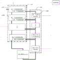
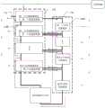
图16为根据本公开一实施例提供的一种液化气体储能发电装置的示意图。如图16所示,气体压缩膨胀单元110包括N个压缩膨胀模块1100,N 个压缩膨胀模块1100包括N个控温液体源150,N个压缩膨胀模块1100串联设置以对来自气体端口112的气体进行分级压缩和膨胀,N为大于1的正整数。由此,通过N个压缩膨胀模块对来自气体端口的气体进行分级压缩和膨胀,可在气体压力不大的压缩膨胀模块中使用耐压强度较低的设备,在气体压力大的压缩膨胀模块中使用耐压强度高的设备,从而可从整体上降低设备的成本。FIG. 16 is a schematic diagram of a liquefied gas energy storage power generation device according to an embodiment of the present disclosure. As shown in FIG. 16 , the gas compression-
例如,在一些示例中,如图16所示,N个控温液体源150与N个压缩膨胀模块1100一一对应设置,压缩膨胀模块1100被配置为利用对应设置的控温液体源150来进行等温压缩,N个控温液体源150中各控温液体源的液体的温度范围不同。需要说明的是,本公开实施例包括但不限于此,N个控温液体源150中各控温液体源的液体的温度范围也可相同。For example, in some examples, as shown in FIG. 16 , N temperature-controlling
例如,在一些示例中,上述的热电交换模块也可采用其他设备来实现。例如,热电交换模块可为热泵,可利用电能实现能量转移。例如,热泵可通过气体膨胀吸热和气体压缩放热的方式或蒸发和冷凝的方式消耗电能实现热量转移,并被配置为通过气体在高温液体内等温膨胀和在低温液体内等温压缩的方式或基于热电材料的塞贝克效应的温差发电器实现发电。例如,在一些示例中,如图16所示,热电交换单元130包括N个热电交换模块1300,N个热电交换模块1300与N个控温液体源150一一对应设置,第N个热电交换模块150分别与液化储能单元120与第N个控温液体源150相连,第n 个热电交换模块1300分别与第n个控温液体源150与第n+1个控温液体源 150相连,n为小于N的正整数。由此,N个热电交换模块1300可实现分级换热,从而可从整体上降低设备的成本。For example, in some examples, the thermoelectric exchange modules described above may also be implemented using other devices. For example, the thermoelectric exchange module can be a heat pump, which can utilize electrical energy for energy transfer. For example, a heat pump may consume electrical energy to transfer heat by means of gas expansion and compression, or evaporation and condensation, and configured to perform isothermal expansion of gas in a high temperature liquid and isothermal compression in a low temperature liquid, or Thermoelectric generators based on the Seebeck effect of thermoelectric materials realize power generation. For example, in some examples, as shown in FIG. 16 , the
例如,在一些示例中,如图16所示,该液化气体储能发电装置对气体进行多级压缩膨胀实现液化。该液化气体储能发电装置包括三个部分:气体压缩膨胀单元110、液化储能单元120和热电交换单元130。气体压缩膨胀单元110由N个压缩膨胀模块1100构成,热电交换单元130由N个热电交换模块1300构成;此外,N个压缩膨胀模块1100配置N个控温液体源150, N个热电交换模块1300与N个控温液体源150一一对应设置,第N个热电交换模块150分别与液化储能单元120与第N个控温液体源150相连,第n 个热电交换模块1300分别与第n个控温液体源150与第n+1个控温液体源 150相连,n为小于N的正整数。N个压缩膨胀模块串联设置,即第一个压缩膨胀模块的出口与第二个压缩膨胀模块的入口相连,第二个压缩膨胀模块的出口与第三个压缩膨胀模块的入口相连,以此类推。第N个压缩膨胀模块的出口与液化储能单元120的气体空间相连。N个压缩膨胀模块与N个控温液体源一一对应设置,各压缩膨胀模块利用对应设置的控温液体源来实现等温压缩。For example, in some examples, as shown in FIG. 16 , the liquefied gas energy storage power generation device performs multi-stage compression and expansion on the gas to achieve liquefaction. The liquefied gas energy storage power generation device includes three parts: a gas compression and
图16所示的液化气体储能发电装置在进行储能时,外部气体经气体端口112进入第一个压缩膨胀模块,第一个压缩膨胀模块消耗电能将外部气体转换为特定压强和温度的气体并通过气体管道转移至第二个压缩膨胀模块,第二个压缩膨胀模块消耗电能将外部气体转换为特定压强和温度的气体并通过气体管道转移至第三个压缩膨胀模块,以此类推;最后,第N个压缩膨胀模块消耗电能将外部气体转换为第一个压缩气体并通过气体管道转移至液化储能单元120的气体空间;同时,第一个控温液体源吸收第一个压缩膨胀模块中气体等温压缩的热量维持气体温度恒定,第二个控温液体源吸收第二个压缩膨胀模块中气体等温压缩的热量维持气体温度恒定,以此类推;同时,第一个热电交换模块消耗电能将第二个控温液体源的多余的热量转移至第一个控温液体源以维持第二个控温液体源的温度恒定,第二个热电交换模块消耗电能将第三个控温液体源的多余的热量转移至第二个控温液体源以维持第三个控温液体源的温度恒定,以此类推;第N个热电交换模块消耗电能吸收液化储能单元120液态气体的热量转移至第N个控温液体源;这样液化储能单元120内液态气体温度下降、气态气体压强上升使气体液化,实现电能存储。另外,在该液化气体储能发电装置的运行过程中,液化储能单元 120内气液两相物质通过混合实现热交换,使液化储能单元120内气液两相物质温度保持稳定。When the liquefied gas energy storage power generation device shown in FIG. 16 performs energy storage, the external gas enters the first compression and expansion module through the gas port 112, and the first compression and expansion module consumes electric energy to convert the external gas into a gas with a specific pressure and temperature And transferred to the second compression and expansion module through the gas pipeline, the second compression and expansion module consumes electricity to convert the external gas into gas with a specific pressure and temperature and transferred to the third compression and expansion module through the gas pipeline, and so on; , the Nth compression-expansion module consumes electricity to convert the external gas into the first compressed gas and transfers it to the gas space of the liquefaction energy storage unit 120 through the gas pipeline; at the same time, the first temperature-controlled liquid source absorbs the first compression-expansion module The heat of isothermal compression of the gas in the middle keeps the gas temperature constant, the second temperature-controlled liquid source absorbs the heat of the isothermal compression of the gas in the second compression expansion module to maintain the gas temperature constant, and so on; at the same time, the first thermoelectric exchange module consumes electricity Transfer the excess heat of the second temperature-controlled liquid source to the first temperature-controlled liquid source to maintain the temperature of the second temperature-controlled liquid source constant, and the second thermoelectric exchange module consumes electricity to transfer the third temperature-controlled liquid source. The excess heat is transferred to the second temperature-controlled liquid source to maintain the temperature of the third temperature-controlled liquid source constant, and so on; The Nth temperature-controlled liquid source; in this way, the temperature of the liquid gas in the liquefaction
图16所示的液化气体储能发电装置在进行发电时,第N个热电交换模块利用第N个控温液体源和液化储能单元120中的液态气体的温度差发电,第N个控温液体源的热量转移至液化储能单元120内的液态气体中使液态气体升温,液化储能单元120内的气态气体转移至压缩膨胀单元110,液化储能单元120内液态气体温度上升、气态气体压强下降使液态气体汽化;气态气体经气体管道进入第N个压缩膨胀模块发电后经气体管道进入第N-1个压缩膨胀模块发电,第N-1个压缩膨胀模块发电后的气体经气体管道进入第 N-2个压缩膨胀模块发电,以此类推;最后,气体经气体端口112排出;同时,第N个控温液体源补充第N个压缩膨胀模块中气体等温膨胀的热量维持气体温度恒定,第N-1个控温液体源补充第N-1个压缩膨胀模块中气体等温膨胀的热量维持气体温度恒定,以此类推;同时,第N-1个热电交换模块利用第N-1控温液体源和第N个控温液体源的温度差发电,第N-1个控温液体源的热量转移至第N个控温液体源以维持第N个控温液体源的温度恒定,第N-2个热电交换模块利用第N-2控温液体源和第N-1个控温液体源的温度差发电,第N-2个控温液体源的热量转移至第N-1个控温液体源以维持第N-1个控温液体源的温度恒定,以此类推;在该液化气体储能发电装置的运行过程中,液化储能单元120内气液两相物质通过混合实现热交换,使液化储能单元120内气液两相物质温度保持稳定。When the liquefied gas energy storage power generation device shown in FIG. 16 is generating electricity, the Nth thermoelectric exchange module uses the temperature difference between the Nth temperature-controlling liquid source and the liquid gas in the liquefied
图17为根据本公开一实施例提供的一种液化气体储能发电装置在储能时气体、电能及热量流向的示意图。如图17所示,在液化气体储能发电装置进行储能时,电网300中电能分别流向气体压缩膨胀单元110的压缩膨胀模块1100和热电交换单元130的热电交换模块1300;外部气体经压缩膨胀模块单元110最终进入液化储能单元120的气体空间被液化;各压缩膨胀模块1100的热量分别流入与之对应的控温液体源150;液化储能单元120的液体空间的热量转移至压缩膨胀模块单元110,压缩膨胀模块单元110的热量经热电交换模块最终流出。17 is a schematic diagram illustrating the flow of gas, electric energy and heat during energy storage in a liquefied gas energy storage power generation device according to an embodiment of the present disclosure. As shown in FIG. 17 , when the liquefied gas energy storage power generation device performs energy storage, the electric energy in the
图18为根据本公开一实施例提供的一种液化气体储能发电装置在发电时气体、电能及热量流向的示意图。如图18所示,在液化气体储能发电装置进行发电时,气体压缩膨胀单元110的压缩膨胀模块1100和热电交换单元130的热电交换模块1300发出的电能均流向电网300;液化储能单元120 的气体空间的气态气体经气体端口112最终排出。18 is a schematic diagram illustrating the flow of gas, electric energy and heat during power generation of a liquefied gas energy storage power generation device according to an embodiment of the present disclosure. As shown in FIG. 18 , when the liquefied gas energy storage power generation device generates electricity, the electric energy generated by the
图19为本公开一实施例提供的另一种液化气体储能发电装置的示意图。如图19所示,热电交换单元130包括N+1个热电交换模块1300,N+1个热电交换模块1300与N个气体压缩膨胀单元110150和液化储能单元120一一对应设置,第N+1个热电交换模块1300分别与液化储能单元120与液体源 140相连,第p个热电交换模块1300分别与第p个气体压缩膨胀单元110 的控温液体源150与液体源140相连,p为小于等于N的正整数。由此,各热电交换模块1300可共用一个液体源140。FIG. 19 is a schematic diagram of another liquefied gas energy storage power generation device according to an embodiment of the present disclosure. As shown in FIG. 19 , the
例如,如图19所示,该液化气体储能发电装置对气体进行多级压缩膨胀实现液化,包括三个部分:气体压缩膨胀单元110、液化储能单元120和热电交换单元130。气体压缩膨胀单元110由N个压缩膨胀模块1100构成,热电交换单元130由N+1个热电交换模块1300构成;此外,N个气体压缩膨胀单元110配置N个控温液体源150;液体源140配置1个。N个压缩膨胀模块串联设置,即第一个压缩膨胀模块的出口与第二个压缩膨胀模块的入口相连,第二个压缩膨胀模块的出口与第三个压缩膨胀模块的入口相连,以此类推。第N个压缩膨胀模块的出口与液化储能单元120的气体空间相连。 N个压缩膨胀模块与N个控温液体源一一对应设置,各压缩膨胀模块利用对应设置的控温液体源来实现等温压缩。N+1个热电交换模块1300与N个气体压缩膨胀单元110的N个控温液体源150和液化储能单元120一一对应设置,第N+1个热电交换模块1300分别与液化储能单元120与液体源140相连,第p个热电交换模块1300分别与第p个气体压缩膨胀单元110的控温液体源150与液体源140相连,p为小于等于N的正整数。由此,该液化气体储能发电单元中的N个热电交换模块可共享同一个液体源140。For example, as shown in FIG. 19 , the liquefied gas energy storage power generation device performs multi-stage compression and expansion on gas to achieve liquefaction, and includes three parts: a gas compression and
图19所示的液化气体储能发电装置在进行储能时,外部气体经气体端口112进入第一个压缩膨胀模块,第一个压缩膨胀模块消耗电能将外部气体转换为特定压强和温度的气体并通过气体管道转移至第二个压缩膨胀模块,第二个压缩膨胀模块消耗电能将外部气体转换为特定压强和温度的气体并通过气体管道转移至第三个压缩膨胀模块,以此类推;最后,第N个压缩膨胀模块消耗电能将外部气体转换为第一个压缩气体并通过气体管道转移至液化储能单元120的气体空间;同时,第一个控温液体源吸收第一个压缩膨胀模块中气体等温压缩的热量维持气体温度恒定,第二个控温液体源吸收第二个压缩膨胀模块中气体等温压缩的热量维持气体温度恒定,以此类推;同时,第一个热电交换模块消耗电能将第一个控温液体源的多余的热量转移至液体源以维持第一个控温液体源的温度恒定,第二个热电交换模块消耗电能将第二个控温液体源的多余的热量转移至液体源以维持第二个控温液体源的温度恒定,以此类推;第N+1个热电交换模块消耗电能吸收液化储能单元 120液态气体的热量转移至液体源;这样液化储能单元120内液态气体温度下降、气态气体压强上升使气体液化,实现电能存储。另外,在该液化气体储能发电装置的运行过程中,液化储能单元120内气液两相物质通过混合实现热交换,使液化储能单元120内气液两相物质温度保持稳定。When the liquefied gas energy storage power generation device shown in FIG. 19 is storing energy, the external gas enters the first compression and expansion module through the gas port 112, and the first compression and expansion module consumes electric energy to convert the external gas into a gas with a specific pressure and temperature And transferred to the second compression and expansion module through the gas pipeline, the second compression and expansion module consumes electricity to convert the external gas into gas with a specific pressure and temperature and transferred to the third compression and expansion module through the gas pipeline, and so on; , the Nth compression-expansion module consumes electricity to convert the external gas into the first compressed gas and transfers it to the gas space of the liquefaction energy storage unit 120 through the gas pipeline; at the same time, the first temperature-controlled liquid source absorbs the first compression-expansion module The heat of isothermal compression of the gas in the middle keeps the gas temperature constant, the second temperature-controlled liquid source absorbs the heat of the isothermal compression of the gas in the second compression expansion module to maintain the gas temperature constant, and so on; at the same time, the first thermoelectric exchange module consumes electricity Transfer the excess heat of the first temperature-controlled liquid source to the liquid source to maintain the temperature of the first temperature-controlled liquid source constant, and the second thermoelectric exchange module consumes electricity to transfer the excess heat of the second temperature-controlled liquid source to the liquid source to maintain the temperature of the second temperature control liquid source constant, and so on; In 120, the temperature of the liquid gas drops and the pressure of the gaseous gas rises to liquefy the gas to realize electric energy storage. In addition, during the operation of the liquefied gas energy storage power generation device, the gas-liquid two-phase substances in the liquefied
图19所示的液化气体储能发电装置在进行发电时,第N+1个热电交换模块利用液体源140和液化储能单元120中的液态气体的温度差发电,液体源140转移至液化储能单元120内的液态气体中使液态气体升温,液化储能单元120内的气态气体转移至压缩膨胀单元110,液化储能单元120内液态气体温度上升、气态气体压强下降使液态气体汽化;气态气体经气体管道进入第N个压缩膨胀模块发电后经气体管道进入第N-1个压缩膨胀模块发电,第N-1个压缩膨胀模块发电后的气体经气体管道进入第N-2个压缩膨胀模块发电,以此类推;最后,气体经气体端口112排出;同时,第N个控温液体源补充第N个压缩膨胀模块中气体等温膨胀的热量维持气体温度恒定,第 N-1个控温液体源补充第N-1个压缩膨胀模块中气体等温膨胀的热量维持气体温度恒定,以此类推;同时,第N个热电交换模块利用第N控温液体源和液体源的温度差发电,液体源的热量转移至第N个控温液体源以维持第N 个控温液体源的温度恒定,第N-1个热电交换模块利用第N-1控温液体源和液体源的温度差发电,液体源的多余热量转移至第N-1个控温液体源以维持第N-1个控温液体源的温度恒定,以此类推;在该液化气体储能发电装置的运行过程中,液化储能单元120内气液两相物质通过混合实现热交换,使液化储能单元120内气液两相物质温度保持稳定。When the liquefied gas energy storage power generation device shown in FIG. 19 is generating electricity, the N+1th thermoelectric exchange module utilizes the temperature difference between the
图20为本公开一实施例提供的另一种液化气体储能发电装置的示意图。如图20所示,热电交换单元130包括N+1个热电交换模块1300,N+1个热电交换模块1300与N个气体压缩膨胀单元110的N个控温液体源150和液化储能单元120一一对应设置,第N+1个热电交换模块1300分别与液化储能单元120与第N个温控液体源150相连,第1个热电交换模块1300分别与第1个控温液体源150与液体源140相连,第q个热电交换模块1300分别与第q个控温液体源150与第q-1个控温液体源150相连,q为小于等于 N的正整数。FIG. 20 is a schematic diagram of another liquefied gas energy storage power generation device according to an embodiment of the present disclosure. As shown in FIG. 20 , the
例如,如图20所示,该液化气体储能发电装置对气体进行多级压缩膨胀实现液化,包括三个部分:气体压缩膨胀单元110、液化储能单元120和热电交换单元130。气体压缩膨胀单元110由N个压缩膨胀模块1100构成,热电交换单元130由N+1个热电交换模块1300构成;此外,N个压缩膨胀模块1100配置N个控温液体源150;液体源140配置1个。N个压缩膨胀模块串联设置,即第一个压缩膨胀模块的出口与第二个压缩膨胀模块的入口相连,第二个压缩膨胀模块的出口与第三个压缩膨胀模块的入口相连,以此类推。第N个压缩膨胀模块的出口与液化储能单元120的气体空间相连。N 个压缩膨胀模块与N个控温液体源一一对应设置,各压缩膨胀模块利用对应设置的控温液体源来实现等温压缩。N+1个热电交换模块1300与N个控温液体源150和液化储能单元120一一对应设置,第N+1个热电交换模块1300 分别与液化储能单元120与第N各控温液体模组相连,第p个热电交换模块 1300分别与第p个控温液体源150与第p-1个控温液体源150相连,p为小于等于N的正整数。第1个热电交换模块1300分别与第1个控温液体源150 和液体源130相连。For example, as shown in FIG. 20 , the liquefied gas energy storage power generation device performs multi-stage compression and expansion on gas to achieve liquefaction, and includes three parts: a gas compression and
图20所示的液化气体储能发电装置在进行储能时,外部气体经气体端口112进入第一个压缩膨胀模块,第一个压缩膨胀模块消耗电能将外部气体转换为特定压强和温度的气体并通过气体管道转移至第二个压缩膨胀模块,第二个压缩膨胀模块消耗电能将外部气体转换为特定压强和温度的气体并通过气体管道转移至第三个压缩膨胀模块,以此类推;最后,第N个压缩膨胀模块消耗电能将外部气体转换为第一个压缩气体并通过气体管道转移至液化储能单元120的气体空间;同时,第一个控温液体源吸收第一个压缩膨胀模块中气体等温压缩的热量维持气体温度恒定,第二个控温液体源吸收第二个压缩膨胀模块中气体等温压缩的热量维持气体温度恒定,以此类推;同时,第一个热电交换模块消耗电能将第一个控温液体源的多余的热量转移至液体源以维持第一个控温液体源的温度恒定,第二个热电交换模块消耗电能将第二个控温液体源的多余的热量转移至第一个控温液体源以维持第二个控温液体源的温度恒定,以此类推;第N+1个热电交换模块消耗电能吸收液化储能单元120液态气体的热量转移至第N个控温液体源;这样液化储能单元120内液态气体温度下降、气态气体压强上升使气体液化,实现电能存储。另外,在该液化气体储能发电装置的运行过程中,液化储能单元120内气液两相物质通过混合实现热交换,使液化储能单元120内气液两相物质温度保持稳定。When the liquefied gas energy storage power generation device shown in FIG. 20 performs energy storage, the external gas enters the first compression and expansion module through the gas port 112, and the first compression and expansion module consumes electric energy to convert the external gas into a gas with a specific pressure and temperature And transferred to the second compression and expansion module through the gas pipeline, the second compression and expansion module consumes electricity to convert the external gas into gas with a specific pressure and temperature and transferred to the third compression and expansion module through the gas pipeline, and so on; , the Nth compression-expansion module consumes electricity to convert the external gas into the first compressed gas and transfers it to the gas space of the liquefaction energy storage unit 120 through the gas pipeline; at the same time, the first temperature-controlled liquid source absorbs the first compression-expansion module The heat of isothermal compression of the gas in the middle keeps the gas temperature constant, the second temperature-controlled liquid source absorbs the heat of the isothermal compression of the gas in the second compression expansion module to maintain the gas temperature constant, and so on; at the same time, the first thermoelectric exchange module consumes electricity Transfer the excess heat of the first temperature-controlled liquid source to the liquid source to maintain the temperature of the first temperature-controlled liquid source constant, and the second thermoelectric exchange module consumes electricity to transfer the excess heat of the second temperature-controlled liquid source to the first temperature-controlled liquid source to maintain the temperature of the second temperature-controlled liquid source constant, and so on; Temperature-controlled liquid source; in this way, the temperature of the liquid gas in the liquefaction energy storage unit 120 drops, and the pressure of the gaseous gas rises to liquefy the gas, thereby realizing electrical energy storage. In addition, during the operation of the liquefied gas energy storage power generation device, the gas-liquid two-phase substances in the liquefied
图20所示的液化气体储能发电装置在进行发电时,第N+1个热电交换模块利用第N个控温液体源和液化储能单元120中的液态气体的温度差发电,第N个控温液体源的热量转移至液化储能单元120内的液态气体中使液态气体升温,液化储能单元120内的气态气体转移至压缩膨胀单元110,液化储能单元120内液态气体温度上升、气态气体压强下降使液态气体汽化;气态气体经气体管道进入第N个压缩膨胀模块发电后经气体管道进入第N-1 个压缩膨胀模块发电,第N-1个压缩膨胀模块发电后的气体经气体管道进入第N-2个压缩膨胀模块发电,以此类推;最后,气体经气体端口112排出;同时,第N个控温液体源补充第N个压缩膨胀模块中气体等温膨胀的热量维持气体温度恒定,第N-1个控温液体源补充第N-1个压缩膨胀模块中气体等温膨胀的热量维持气体温度恒定,以此类推;同时,第N+1个热电交换模块利用第N控温液体源和液化储能单元中液体的温度差发电,第N个热电交换模块利用第N个控温液体源和第N-1个控温液体源的温度差发电,第 N-1个控温液体源的热量转移至第N个控温液体源以维持第N个控温液体源的温度恒定,以此类推;第一个热电交换模块利用第1个控温液体源和液体源的温度差发电;在该液化气体储能发电装置的运行过程中,液化储能单元 120内气液两相物质通过混合实现热交换,使液化储能单元120内气液两相物质温度保持稳定。When the liquefied gas energy storage power generation device shown in FIG. 20 is generating electricity, the N+1th thermoelectric exchange module uses the temperature difference between the Nth temperature-controlled liquid source and the liquid gas in the liquefied
图21为本公开一实施例提供的另一种液化气体储能发电装置的示意图。如图21和图22所示,来自气体端口的气体包括M个气体组分,液化储能单元120包括M个液化储能模块1200,第M个液化储能模块1200与第N 个压缩膨胀模块1100相连,第g个液化储能模块1200与第k个压缩膨胀模块1100相连,第g个液化储能模块1200被配置为存储液化后的第g个气体组分,第g个气体组分的液化温度小于或等于与第k个压缩膨胀模块100对应设置的控温液体源150中液体的温度,g为小于M的正整数,k为小于N 的正整数。FIG. 21 is a schematic diagram of another liquefied gas energy storage power generation device according to an embodiment of the present disclosure. As shown in FIG. 21 and FIG. 22 , the gas from the gas port includes M gas components, the liquefaction
例如,在一些示例中,第g个液化储能模块可用于将来自气体端口中的第g个气体组分分离出来,以实现其他用途,从而可提高该液化气体储能发电装置的综合经济效益。例如,来自气体端口中的气体为空气,第g个气体组分可为氧气。For example, in some examples, the g-th liquefied energy storage module can be used to separate the g-th gas component from the gas port for other purposes, thereby improving the comprehensive economic benefits of the liquefied gas energy storage power generation device . For example, the gas from the gas port is air and the g-th gas component can be oxygen.
例如,在一些示例中,如图21所示,该液化气体储能发电装置对气体进行多级液化分离。来自气体端口的气体包括M个气体组分,例如,空气可包括氮气、氧气、二氧化碳等气体。液化储能单元120包括M个液化储能模块1200,也就是说,液化储能模块的数量可以与气体组分的数量相同,以分别存储对应的液化气体组分。第M个液化储能模块1200与第N个压缩膨胀模块1100相连,也就是说,第M个液化储能模块存储第N个压缩膨胀模块的产物;第g个液化储能模块1200与第k个压缩膨胀模块1100相连,第g个液化储能模块1200被配置为存储液化后的第g个气体组分,第g个气体组分的液化温度小于或等于与第k个压缩膨胀模块100对应设置的控温液体源150中液体的温度,g为小于M的正整数,k为小于N的正整数。由此,该液化气体储能发电装置不仅可以进行储能发电,还可利用M个液化储能模块来实现气体中组分的分离和利用。需要说明的是,压缩膨胀模块的数量可等于液化储能模块的数量,也可大于液化储能模块的数量。For example, in some examples, as shown in FIG. 21 , the liquefied gas energy storage power generation device performs multi-stage liquefaction separation on gas. The gas from the gas port includes M gas components, for example, air may include nitrogen, oxygen, carbon dioxide, etc. gases. The liquefied
例如,在一些示例中,如图22所示,压缩膨胀模块的数量大于液化储能模块的数量,也就是说,M个液化储能模块可根据压缩膨胀模块对应设置的控温液体源中液体的温度插入N个串联设置的压缩膨胀模块之中。在压缩膨胀模块的分级压缩和膨胀过程中,由于气体中各组分的气体液化温度都比较低,需要经过多个压缩膨胀模组分级压缩和膨胀之后才能到达气体中各组分中液化温度最高的组分所需的液化温度。例如,第g个液化储能模块1200 与第k个压缩膨胀模块1100相连,第g个液化储能模块1200被配置为存储液化后的第g个气体组分,第g个气体组分的液化温度小于或等于与第k个压缩膨胀模块100对应设置的控温液体源150中液体的温度,g为小于M的正整数,k为小于N的正整数。外部气体在多个压缩膨胀模块的连续压缩之后完成某一组分的液化后,第一液化储能模组的气体空间的气态气体将不再含有这一组分或含量极小,第一液化储能模组的气体空间的气态气体进入下一个压缩膨胀模块或多个压缩膨胀模块以完成另一组分的液化,以此类推。最终实现外部气体分级液化分离。For example, in some examples, as shown in FIG. 22 , the number of compression-expansion modules is greater than the number of liquefied energy storage modules, that is, M liquefied energy storage modules can be based on the liquid in the temperature-controlled liquid source corresponding to the compression-expansion modules. The temperature is inserted into N compression expansion modules arranged in series. During the staged compression and expansion process of the compression-expansion module, since the gas liquefaction temperature of each component in the gas is relatively low, it is necessary to undergo staged compression and expansion of multiple compression-expansion modules to reach the highest liquefaction temperature of each component in the gas. the desired liquefaction temperature of the components. For example, the g-th liquefaction
例如,在一些示例中,液化储能模组与下一级的气体压缩膨胀模组之间可增加过滤装置以过滤残留的未液化的这一组分,从而可提高液化后的各气体组分的纯度。For example, in some examples, a filter device can be added between the liquefied energy storage module and the gas compression and expansion module of the next stage to filter the remaining unliquefied component, so as to improve the liquefied gas components purity.
图23为本公开一实施例提供的一种液化气体储能发电装置的液化储能单元液体空间连接外部储气空间的示意图。利用电机122将液化储能单元 120的液体空间124的液态空气经液体管道125送入外部储气空间121,与外部储气空间121内的气体热交换后进入气体空间126构成液态空气的循环流动。外部储气空间121内的气体与液体空间124的液化空气的温度和压强均不同。外部储气空间121内的气体由气体管道123与外界气体源构成气体的循环流动。23 is a schematic diagram of a liquid space of a liquefied energy storage unit of a liquefied gas energy storage power generation device connected to an external gas storage space according to an embodiment of the present disclosure. The
例如,液化储能单元120在储能时,液体空间124内存储压强为3MPa、温度为-150℃的液态空气,外界气体源为外部储气空间121充入压强为 1MPa、温度为-160℃的氮气并使其经气体管道123构成气体的循环流动。在电机122的作用下,液体空间124内的液态空气经液体管道125送入外部储气空间121,液态空气与氮气发生热交换,液态空气热量转移至氮气中,液态空气热交换后进入气体空间126构成液态空气的循环流动。液态空气与氮气的循环流动使液体空间124的液态空气热量转移至氮气中,促进液化过程的进行,以实现不同压强下具有不同温度的同种介质之间的热量交换。For example, when the liquefied
例如,外部气体源为热电交换模块1300的第一气体等温压缩膨胀装置或第二气体等温压缩膨胀装置。第一气体等温压缩膨胀装置或第二气体等温压缩膨胀装置内的气体经过经气体管道123循环流动的同时实现压缩或膨胀过程。For example, the external gas source is the first gas isothermal compression expansion device or the second gas isothermal compression expansion device of the
本公开一实施例还提供一种液化气体储能发电装置的储能发电方法,该液化气体储能发电装置为上述任一项描述的液化气体储能发电装置,该储能发电方法包括以下步骤:An embodiment of the present disclosure further provides an energy storage and power generation method for a liquefied gas energy storage power generation device, the liquefied gas energy storage power generation device is the liquefied gas energy storage power generation device described in any one of the above, and the energy storage power generation method includes the following steps :
步骤S101:储能阶段,通过气体端口向气体压缩膨胀单元通入气体;步骤S102:气体压缩膨胀单元利用电能压缩来自气体端口的气体以形成第一压缩气体并将第一压缩气体输送至液化储能单元;Step S101: In the energy storage stage, gas is introduced into the gas compression and expansion unit through the gas port; Step S102: The gas compression and expansion unit utilizes electrical energy to compress the gas from the gas port to form the first compressed gas and deliver the first compressed gas to the liquefaction storage unit. energy unit;
步骤S103:热电交换单元利用电能吸收液化储能单元中液态气体的热量并将热量转移至液体源以使第一压缩气体在液化储能单元液化;Step S103: the thermoelectric exchange unit utilizes electric energy to absorb the heat of the liquid gas in the liquefaction energy storage unit and transfers the heat to the liquid source to liquefy the first compressed gas in the liquefaction energy storage unit;
步骤S104:在发电阶段,热电交换单元利用液体源与液化储能单元中液态气体的温差进行发电并将液体源的热量转移至液化储能单元中液态气体以使液化储能单元中液态气体气化;以及Step S104: In the power generation stage, the thermoelectric exchange unit utilizes the temperature difference between the liquid source and the liquid gas in the liquefied energy storage unit to generate electricity and transfers the heat of the liquid source to the liquid gas in the liquefied energy storage unit to make the liquid gas in the liquefied energy storage unit and
步骤S105:气体压缩膨胀单元还被配置为利用液化储能单元中的气体进行发电。Step S105: The gas compression and expansion unit is further configured to generate electricity by using the gas in the liquefied energy storage unit.
由此,在本实施例提供的液化气体储能发电装置的储能发电方法中,在进行储能时,气体压缩膨胀单元可消耗电能来压缩来自气体端口的气体(例如,空气)以形成第一压缩气体(具有特定压强和温度的气体)并将第一压缩气体输送至液化储能单元,热电交换单元可消耗电能吸收液化储能单元中液态气体的热量并将热量转移至液体源以使第一压缩气体在液化储能单元中液化,从而将电能存储在液化气体中。由于液化气体的体积较小,存储的能量较高,因此该液化气体储能发电技术的存储容量比较大,而所占用的体积则相对较小。另一方面,液化气体无污染、对环境友好、成本较低,因此该液化气体储能发电装置具有无污染、对环境友好、储能成本较低、经济效益高等优点。当本实施例提供的液化气体储能发电装置进行发电时,热电交换单元还被配置为利用液体源与液化储能单元中液态气体的温差进行发电并将液体源的热量转移至液化储能单元中液态气体,使液态气体汽化以使液化储能单元中液态气体气化,气体压缩膨胀单元还被配置为利用液化储能单元中的气体进行膨胀做功以进行发电。并且,该液化气体储能发电装置的能量利用效率较高。需要说明的是,在本实施例提供的液化气体储能发电装置的运行过程中,液化储能单元内气液两相物质通过混合实现热交换,从而可使液化储能单元内气液两相物质温度保持稳定。Therefore, in the energy storage power generation method of the liquefied gas energy storage power generation device provided in this embodiment, when energy storage is performed, the gas compression and expansion unit can consume electrical energy to compress the gas (eg, air) from the gas port to form the first A compressed gas (gas with a specific pressure and temperature) and the first compressed gas is delivered to the liquefied energy storage unit, the thermoelectric exchange unit can consume electrical energy to absorb the heat of the liquid gas in the liquefied energy storage unit and transfer the heat to the liquid source to make The first compressed gas is liquefied in the liquefied energy storage unit, thereby storing electrical energy in the liquefied gas. Since the volume of the liquefied gas is small and the stored energy is high, the storage capacity of the liquefied gas energy storage power generation technology is relatively large, and the occupied volume is relatively small. On the other hand, liquefied gas is non-polluting, environmentally friendly, and low in cost, so the liquefied gas energy storage power generation device has the advantages of no pollution, environmental friendliness, low energy storage cost, and high economic benefits. When the liquefied gas energy storage power generation device provided in this embodiment generates electricity, the thermoelectric exchange unit is further configured to use the temperature difference between the liquid source and the liquid gas in the liquefied energy storage unit to generate electricity and transfer the heat of the liquid source to the liquefied energy storage unit The liquid gas in the liquefied energy storage unit is vaporized to vaporize the liquid gas in the liquefied energy storage unit, and the gas compression and expansion unit is further configured to utilize the gas in the liquefied energy storage unit to perform expansion and work to generate electricity. In addition, the energy utilization efficiency of the liquefied gas energy storage power generation device is relatively high. It should be noted that, during the operation of the liquefied gas energy storage power generation device provided in this embodiment, the gas-liquid two-phase substances in the liquefied energy storage unit are mixed to realize heat exchange, so that the gas-liquid two-phase materials in the liquefied energy storage unit can be exchanged. The material temperature remains stable.
例如,在一些示例中,在储能阶段,气体压缩膨胀单元利用电能对来自气体端口的气体进行等温压缩。For example, in some examples, the gas compression expansion unit utilizes electrical energy to isothermally compress the gas from the gas port during the energy storage phase.
有以下几点需要说明:The following points need to be noted:
(1)本发明实施例附图中,只涉及到与本发明实施例涉及到的结构,其他结构可参考通常设计。(1) In the drawings of the embodiments of the present invention, only the structures involved in the embodiments of the present invention are involved, and other structures may refer to general designs.
(2)在不冲突的情况下,本发明同一实施例及不同实施例中的特征可以相互组合。(2) The features of the same embodiment and different embodiments of the present invention may be combined with each other without conflict.
以上,仅为本公开的具体实施方式,但本公开的保护范围并不局限于此,任何熟悉本技术领域的技术人员在本公开揭露的技术范围内,可轻易想到变化或替换,都应涵盖在本公开的保护范围之内。因此,本公开的保护范围应以权利要求的保护范围为准。The above are only specific embodiments of the present disclosure, but the protection scope of the present disclosure is not limited thereto. Any person skilled in the art who is familiar with the technical scope of the present disclosure can easily think of changes or substitutions, which should cover within the scope of protection of the present disclosure. Therefore, the protection scope of the present disclosure should be subject to the protection scope of the claims.
Claims (21)
Translated fromChinesePriority Applications (1)
| Application Number | Priority Date | Filing Date | Title |
|---|---|---|---|
| CN201810337946.5ACN108590790B (en) | 2018-04-16 | 2018-04-16 | Liquefied gas energy storage power generation device and energy storage power generation method thereof |
Applications Claiming Priority (1)
| Application Number | Priority Date | Filing Date | Title |
|---|---|---|---|
| CN201810337946.5ACN108590790B (en) | 2018-04-16 | 2018-04-16 | Liquefied gas energy storage power generation device and energy storage power generation method thereof |
Publications (2)
| Publication Number | Publication Date |
|---|---|
| CN108590790A CN108590790A (en) | 2018-09-28 |
| CN108590790Btrue CN108590790B (en) | 2020-10-09 |
Family
ID=63622640
Family Applications (1)
| Application Number | Title | Priority Date | Filing Date |
|---|---|---|---|
| CN201810337946.5AActiveCN108590790B (en) | 2018-04-16 | 2018-04-16 | Liquefied gas energy storage power generation device and energy storage power generation method thereof |
Country Status (1)
| Country | Link |
|---|---|
| CN (1) | CN108590790B (en) |
Families Citing this family (4)
| Publication number | Priority date | Publication date | Assignee | Title |
|---|---|---|---|---|
| CN111561430A (en)* | 2020-04-23 | 2020-08-21 | 北京航空航天大学 | A kind of isothermal expansion device based on gas dissolution and gas-liquid conversion and using method |
| CN112855495B (en)* | 2021-01-20 | 2021-11-05 | 北京航空航天大学 | Liquid-driven ultrahigh-pressure compressed air energy storage system and method thereof |
| CN115207397A (en)* | 2022-09-08 | 2022-10-18 | 国网浙江省电力有限公司宁波供电公司 | Hydrogen fuel cell and compressed air energy storage combined operation system and control method thereof |
| CN115224305A (en)* | 2022-09-14 | 2022-10-21 | 国网浙江省电力有限公司宁波供电公司 | Hydrogen fuel cell power generation system and control method thereof |
Family Cites Families (6)
| Publication number | Priority date | Publication date | Assignee | Title |
|---|---|---|---|---|
| GB0603895D0 (en)* | 2006-02-27 | 2006-04-05 | Highview Entpr Ltd | Energy storage system |
| EP2619420A2 (en)* | 2010-09-20 | 2013-07-31 | State of Oregon acting by and through the State Board of Higher Education on behalf of Oregon State University | A system and method for storing energy and purifying fluid |
| GB2493726A (en)* | 2011-08-16 | 2013-02-20 | Alstom Technology Ltd | Adiabatic compressed air energy storage system |
| EP3384143B1 (en)* | 2015-12-03 | 2022-09-07 | Cheesecake Energy Ltd. | Energy storage system |
| CN106949002A (en)* | 2017-04-06 | 2017-07-14 | 华北电力大学 | A kind of new water-electricity cogeneration ocean energy utilization system |
| CN107124121A (en)* | 2017-05-14 | 2017-09-01 | 罗振波 | A kind of device of the thermo-electric generation of utilization hot and cold water |
- 2018
- 2018-04-16CNCN201810337946.5Apatent/CN108590790B/enactiveActive
Also Published As
| Publication number | Publication date |
|---|---|
| CN108590790A (en) | 2018-09-28 |
Similar Documents
| Publication | Publication Date | Title |
|---|---|---|
| Sun et al. | Design and thermodynamic performance analysis of a new liquid carbon dioxide energy storage system with low pressure stores | |
| CN108590790B (en) | Liquefied gas energy storage power generation device and energy storage power generation method thereof | |
| CN114320504B (en) | Liquid transcritical carbon dioxide energy storage system and method | |
| CN110578567B (en) | Compressed air constant-pressure energy storage power generation system utilizing working medium phase change | |
| Yu et al. | A review of compressed-air energy storage | |
| US8234862B2 (en) | Systems and methods for combined thermal and compressed gas energy conversion systems | |
| US8387375B2 (en) | Systems and methods for optimizing thermal efficiency of a compressed air energy storage system | |
| CN105179033B (en) | The system and its operation method of a kind of utilization cryogenic cold energy storage electric energy | |
| CN107542649A (en) | Low-temperature high-pressure liquid air energy storage system | |
| CN105370407B (en) | Low-temperature liquid air energy storage system | |
| CN114135349B (en) | Thermal power plant waste heat recycling method and energy storage power generation system coupled with thermal power plant | |
| Cheng et al. | Thermodynamic analysis for high-power electricity generation systems based on closed-Brayton-cycle with finite cold source on hypersonic vehicles | |
| CN112963207A (en) | Liquefied air hybrid energy storage and power generation integrated system and method | |
| CN114856738A (en) | A combined cooling, heating and power energy storage system and method based on liquid carbon dioxide storage | |
| CN207795526U (en) | A kind of compressed-air energy-storage system forcing precooling suitable for peak load regulation network band | |
| CN106321343A (en) | Isothermal compression air energy storage power generation system based on liquid temperature control and method thereof | |
| US20180180019A1 (en) | Energy Storage and Power Generation System and Method | |
| CN105736056B (en) | Liquid air energy storage system | |
| CN105697066A (en) | Low-temperature liquid air energy storage system | |
| CN118089261A (en) | Compressed carbon dioxide energy storage system and method for constant-pressure supercritical state storage | |
| CN114221360A (en) | Energy storage method of regenerative heat pump and regenerative heat pump energy storage system | |
| CN114033517A (en) | Geothermal power generation and cold and heat supply system based on carbon dioxide compression energy storage and operation method | |
| Wang et al. | Thermodynamic analysis of novel carbon dioxide pumped-thermal energy storage system | |
| CN105352265B (en) | Liquid precooling working medium cold storage system | |
| CN114382565B (en) | Energy storage power generation system with combined cooling, heating and power |
Legal Events
| Date | Code | Title | Description |
|---|---|---|---|
| PB01 | Publication | ||
| PB01 | Publication | ||
| SE01 | Entry into force of request for substantive examination | ||
| SE01 | Entry into force of request for substantive examination | ||
| GR01 | Patent grant | ||
| GR01 | Patent grant |