CN108528745B - A UAV battery swap charging system - Google Patents
A UAV battery swap charging systemDownload PDFInfo
- Publication number
- CN108528745B CN108528745BCN201810301956.3ACN201810301956ACN108528745BCN 108528745 BCN108528745 BCN 108528745BCN 201810301956 ACN201810301956 ACN 201810301956ACN 108528745 BCN108528745 BCN 108528745B
- Authority
- CN
- China
- Prior art keywords
- charging
- battery
- joint
- control system
- detachable
- Prior art date
- Legal status (The legal status is an assumption and is not a legal conclusion. Google has not performed a legal analysis and makes no representation as to the accuracy of the status listed.)
- Active
Links
Images


Classifications
- B—PERFORMING OPERATIONS; TRANSPORTING
- B64—AIRCRAFT; AVIATION; COSMONAUTICS
- B64F—GROUND OR AIRCRAFT-CARRIER-DECK INSTALLATIONS SPECIALLY ADAPTED FOR USE IN CONNECTION WITH AIRCRAFT; DESIGNING, MANUFACTURING, ASSEMBLING, CLEANING, MAINTAINING OR REPAIRING AIRCRAFT, NOT OTHERWISE PROVIDED FOR; HANDLING, TRANSPORTING, TESTING OR INSPECTING AIRCRAFT COMPONENTS, NOT OTHERWISE PROVIDED FOR
- B64F1/00—Ground or aircraft-carrier-deck installations
- B—PERFORMING OPERATIONS; TRANSPORTING
- B60—VEHICLES IN GENERAL
- B60L—PROPULSION OF ELECTRICALLY-PROPELLED VEHICLES; SUPPLYING ELECTRIC POWER FOR AUXILIARY EQUIPMENT OF ELECTRICALLY-PROPELLED VEHICLES; ELECTRODYNAMIC BRAKE SYSTEMS FOR VEHICLES IN GENERAL; MAGNETIC SUSPENSION OR LEVITATION FOR VEHICLES; MONITORING OPERATING VARIABLES OF ELECTRICALLY-PROPELLED VEHICLES; ELECTRIC SAFETY DEVICES FOR ELECTRICALLY-PROPELLED VEHICLES
- B60L53/00—Methods of charging batteries, specially adapted for electric vehicles; Charging stations or on-board charging equipment therefor; Exchange of energy storage elements in electric vehicles
- B60L53/80—Exchanging energy storage elements, e.g. removable batteries
- H—ELECTRICITY
- H01—ELECTRIC ELEMENTS
- H01M—PROCESSES OR MEANS, e.g. BATTERIES, FOR THE DIRECT CONVERSION OF CHEMICAL ENERGY INTO ELECTRICAL ENERGY
- H01M50/00—Constructional details or processes of manufacture of the non-active parts of electrochemical cells other than fuel cells, e.g. hybrid cells
- H01M50/20—Mountings; Secondary casings or frames; Racks, modules or packs; Suspension devices; Shock absorbers; Transport or carrying devices; Holders
- H—ELECTRICITY
- H01—ELECTRIC ELEMENTS
- H01M—PROCESSES OR MEANS, e.g. BATTERIES, FOR THE DIRECT CONVERSION OF CHEMICAL ENERGY INTO ELECTRICAL ENERGY
- H01M50/00—Constructional details or processes of manufacture of the non-active parts of electrochemical cells other than fuel cells, e.g. hybrid cells
- H01M50/50—Current conducting connections for cells or batteries
- B—PERFORMING OPERATIONS; TRANSPORTING
- B60—VEHICLES IN GENERAL
- B60L—PROPULSION OF ELECTRICALLY-PROPELLED VEHICLES; SUPPLYING ELECTRIC POWER FOR AUXILIARY EQUIPMENT OF ELECTRICALLY-PROPELLED VEHICLES; ELECTRODYNAMIC BRAKE SYSTEMS FOR VEHICLES IN GENERAL; MAGNETIC SUSPENSION OR LEVITATION FOR VEHICLES; MONITORING OPERATING VARIABLES OF ELECTRICALLY-PROPELLED VEHICLES; ELECTRIC SAFETY DEVICES FOR ELECTRICALLY-PROPELLED VEHICLES
- B60L2200/00—Type of vehicles
- B60L2200/10—Air crafts
- H—ELECTRICITY
- H01—ELECTRIC ELEMENTS
- H01M—PROCESSES OR MEANS, e.g. BATTERIES, FOR THE DIRECT CONVERSION OF CHEMICAL ENERGY INTO ELECTRICAL ENERGY
- H01M2220/00—Batteries for particular applications
- H01M2220/20—Batteries in motive systems, e.g. vehicle, ship, plane
- Y—GENERAL TAGGING OF NEW TECHNOLOGICAL DEVELOPMENTS; GENERAL TAGGING OF CROSS-SECTIONAL TECHNOLOGIES SPANNING OVER SEVERAL SECTIONS OF THE IPC; TECHNICAL SUBJECTS COVERED BY FORMER USPC CROSS-REFERENCE ART COLLECTIONS [XRACs] AND DIGESTS
- Y02—TECHNOLOGIES OR APPLICATIONS FOR MITIGATION OR ADAPTATION AGAINST CLIMATE CHANGE
- Y02E—REDUCTION OF GREENHOUSE GAS [GHG] EMISSIONS, RELATED TO ENERGY GENERATION, TRANSMISSION OR DISTRIBUTION
- Y02E60/00—Enabling technologies; Technologies with a potential or indirect contribution to GHG emissions mitigation
- Y02E60/10—Energy storage using batteries
- Y—GENERAL TAGGING OF NEW TECHNOLOGICAL DEVELOPMENTS; GENERAL TAGGING OF CROSS-SECTIONAL TECHNOLOGIES SPANNING OVER SEVERAL SECTIONS OF THE IPC; TECHNICAL SUBJECTS COVERED BY FORMER USPC CROSS-REFERENCE ART COLLECTIONS [XRACs] AND DIGESTS
- Y02—TECHNOLOGIES OR APPLICATIONS FOR MITIGATION OR ADAPTATION AGAINST CLIMATE CHANGE
- Y02T—CLIMATE CHANGE MITIGATION TECHNOLOGIES RELATED TO TRANSPORTATION
- Y02T10/00—Road transport of goods or passengers
- Y02T10/60—Other road transportation technologies with climate change mitigation effect
- Y02T10/70—Energy storage systems for electromobility, e.g. batteries
- Y—GENERAL TAGGING OF NEW TECHNOLOGICAL DEVELOPMENTS; GENERAL TAGGING OF CROSS-SECTIONAL TECHNOLOGIES SPANNING OVER SEVERAL SECTIONS OF THE IPC; TECHNICAL SUBJECTS COVERED BY FORMER USPC CROSS-REFERENCE ART COLLECTIONS [XRACs] AND DIGESTS
- Y02—TECHNOLOGIES OR APPLICATIONS FOR MITIGATION OR ADAPTATION AGAINST CLIMATE CHANGE
- Y02T—CLIMATE CHANGE MITIGATION TECHNOLOGIES RELATED TO TRANSPORTATION
- Y02T10/00—Road transport of goods or passengers
- Y02T10/60—Other road transportation technologies with climate change mitigation effect
- Y02T10/7072—Electromobility specific charging systems or methods for batteries, ultracapacitors, supercapacitors or double-layer capacitors
Landscapes
- Engineering & Computer Science (AREA)
- Mechanical Engineering (AREA)
- Chemical & Material Sciences (AREA)
- Chemical Kinetics & Catalysis (AREA)
- Electrochemistry (AREA)
- General Chemical & Material Sciences (AREA)
- Power Engineering (AREA)
- Transportation (AREA)
- Aviation & Aerospace Engineering (AREA)
- Charge And Discharge Circuits For Batteries Or The Like (AREA)
Abstract
Description
Translated fromChinese技术领域technical field
本发明涉及一种无人机电池更换系统,属于机械技术领域。The invention relates to an unmanned aerial vehicle battery replacement system, which belongs to the technical field of machinery.
背景技术Background technique
无人机是利用无线电遥控设备和自备的程序控制装置操纵的不载人飞机,或者由车载计算机完全地或间歇地自主地操作的不载人飞机。与有人驾驶飞机相比,无人机往往更适合那些太“愚钝,肮脏或危险”的任务。目前,无人机在航拍、农业、植保、微型自拍、快递运输、灾难救援、观察野生动物、监控传染病、测绘、新闻报道、电力巡检、救灾、影视拍摄、制造浪漫等等领域的应用,大大的拓展了无人机本身的用途,发达国家也在积极扩展行业应用与发展无人机技术。Unmanned aerial vehicles are unmanned aircraft operated by radio remote control equipment and self-contained program control devices, or fully or intermittently operated autonomously by on-board computers. Drones tend to be better suited for tasks that are too "dumb, dirty or dangerous" than manned aircraft. At present, drones are used in aerial photography, agriculture, plant protection, miniature selfie, express transportation, disaster rescue, observation of wild animals, monitoring of infectious diseases, surveying and mapping, news reporting, power inspection, disaster relief, film and television shooting, romance and other fields. , greatly expanding the use of the drone itself, and developed countries are also actively expanding industry applications and developing drone technology.
目前,无人机电池已发展到相当成熟的阶段,继续通过电池领域的突破来提高无人机使用效率,成本高、进展慢;同时,要提高无人机续航时间,就要增大电池容量,而电池容量的增大势必导致电池重量增大,从而增加无人机耗电,反过来缩短续航时间。无人机电池普遍续航时间较短,这一缺陷严重阻碍了其产业化的发展。At present, UAV batteries have developed to a fairly mature stage. Continuing to improve the use efficiency of UAVs through breakthroughs in the battery field is costly and slow. At the same time, to improve the battery life of UAVs, it is necessary to increase the battery capacity. , and the increase in battery capacity will inevitably lead to an increase in the weight of the battery, thereby increasing the power consumption of the drone, which in turn shortens the battery life. The battery life of drones is generally short, and this defect seriously hinders the development of its industrialization.
现在已有无人机换电池系统的实用新型专利为提高无人机续航能力提供了一种全新的思路。其原理是通过视觉识别系统识别无人机,使其按照一定的方向降落在无人机平台上,无人机上设有水平插接的电池组,电池组与无人机卡接固定,平台上设有与该电池组相对的换电池装置,换电池装置包括若干个将无人机电池组拉出的空电池槽和若干个装有充满电电池的储备电池槽,电池槽内部设有推拉装置,无人机电池拉出后储备电池槽对准无人机将电池推入,从而完成无人机电池的快速更换。Now there are utility model patents for UAV battery replacement systems, which provide a new idea for improving the endurance of UAVs. The principle is to identify the drone through the visual recognition system, and make it land on the drone platform in a certain direction. The drone is equipped with a horizontally plugged battery pack. There is a battery replacement device opposite to the battery pack. The battery replacement device includes a number of empty battery slots for pulling out the UAV battery pack and a number of reserve battery slots with fully charged batteries, and a push-pull device is arranged inside the battery slot. , after the drone battery is pulled out, the reserve battery slot is aligned with the drone and the battery is pushed in, so as to complete the rapid replacement of the drone battery.
但是,此专利提供的无人机换电池系统应用范围小,实现成本高。首先,其只针对特定的水平插接电池组的无人机,且在无人机上增加视觉识别模块,既增加无人机重量,也影响无人机平衡,同时视觉识别过程中的图像处理也需要额外耗电;其次,无人机具有空间三维运动能力,空中环境复杂,保持稳定飞行本就需要飞行控制系统不断调整姿态,在降落过程中加上视觉识别发出的指令,极有可能对无人机本身的稳定飞行产生影响;最后,无人机视觉识别系统的开发困难大、成本高。However, the UAV battery replacement system provided by this patent has a small application range and a high implementation cost. First of all, it is only for a specific drone with a battery pack inserted horizontally, and adding a visual recognition module to the drone not only increases the weight of the drone, but also affects the balance of the drone. At the same time, the image processing in the visual recognition process also Additional power consumption is required; secondly, the UAV has the ability to move three-dimensionally in space, and the air environment is complex. To maintain a stable flight, the flight control system needs to continuously adjust the attitude, and the instructions issued by visual recognition are added during the landing process. The stable flight of the man-machine itself has an impact; finally, the development of the UAV visual recognition system is difficult and costly.
因此,急需找到一种新的能提高无人机续航能力且应用范围大、实现成本低、对无人机飞行无不良影响的方法。Therefore, it is urgent to find a new method that can improve the endurance of UAVs, has a wide range of applications, has low implementation costs, and has no adverse effects on UAV flight.
发明内容SUMMARY OF THE INVENTION
为解决上述问题,本发明提供了一种无人机电池换接充电系统,此系统包含一种可拆卸电池以及一种可拆卸电池换接充电装置。本发明提供的这种系统具有提高无人机使用效率、整体上增加无人机续航时间、应用范围广、开发周期短、难度适中、实现成本低的优势。In order to solve the above problems, the present invention provides a battery swapping and charging system for drones, which includes a detachable battery and a detachable battery swapping and charging device. The system provided by the invention has the advantages of improving the use efficiency of the UAV, increasing the endurance time of the UAV as a whole, wide application range, short development period, moderate difficulty and low implementation cost.
本发明的技术方案如下:The technical scheme of the present invention is as follows:
本发明提供了一种可拆卸电池,其包含可拆卸电池装置(1)以及电池连接装置(2);所述可拆卸电池装置(1)包含电池(3)、电池仓(4)以及第一接头(5);所述电池连接装置包含连接板(6)、第二接头(7)以及夹紧装置(8);所述电池(3)放置于电池仓(4)仓体内部;所述第一接头(5)底部与电池仓(4)仓体外部相连;所述第一接头(5)顶部含有同心圆槽(9);所述第一接头(5)顶部的同心圆槽(9)中装有压簧片(10);所述压簧片(10)通过导线分别与电池(3)的正负极相连;所述第一接头(5)外侧设有斜坡(11);所述第二接头(7)顶部与连接板(6)相连;所述第二接头(7)内部与连接板(6)相连处含有同心圆槽(9);所述第二接头(7)内部的同心圆槽(9)中装有铜极(12);所述铜极(12)与导线相连;所述夹紧装置(8)包含复位弹簧(13)以及夹手(14);所述复位弹簧(13)与夹手(14)相连;所述夹手(14)通过螺钉(22)连接于第二接头(7)外侧;所述第一接头(5)与第二接头(7)相啮合;所述铜极(12)与压簧片(10)相啮合;所述夹手(14)与第一接头(5)外侧的斜坡(11)啮合。The present invention provides a detachable battery, comprising a detachable battery device (1) and a battery connection device (2); the detachable battery device (1) includes a battery (3), a battery compartment (4) and a first a connector (5); the battery connection device includes a connecting plate (6), a second connector (7) and a clamping device (8); the battery (3) is placed inside the battery compartment (4); the The bottom of the first connector (5) is connected to the outside of the battery compartment (4); the top of the first connector (5) contains a concentric circular groove (9); the concentric circular groove (9) on the top of the first connector (5) ) is equipped with a pressure spring (10); the pressure spring (10) is respectively connected with the positive and negative poles of the battery (3) through wires; the outer side of the first joint (5) is provided with a slope (11); The top of the second joint (7) is connected with the connecting plate (6); the inner part of the second joint (7) is connected with the connecting plate (6) and contains concentric circular grooves (9); the second joint (7) is inside The copper pole (12) is installed in the concentric circular groove (9) of the copper pole; the copper pole (12) is connected with the wire; the clamping device (8) includes a return spring (13) and a clamping hand (14); the The return spring (13) is connected with the gripping hand (14); the gripping hand (14) is connected to the outside of the second joint (7) through a screw (22); the first joint (5) and the second joint (7) The copper pole (12) is engaged with the pressing spring (10); the gripping hand (14) is engaged with the slope (11) on the outer side of the first joint (5).
在本发明的一种实施方式中,所述电池仓(4)为圆盘状。In an embodiment of the present invention, the battery compartment (4) is disc-shaped.
在本发明的一种实施方式中,所述第一接头(5)为圆柱状。In an embodiment of the present invention, the first joint (5) is cylindrical.
在本发明的一种实施方式中,所述第一接头(5)处于电池仓(4)正中位置。In an embodiment of the present invention, the first connector (5) is in the center position of the battery compartment (4).
在本发明的一种实施方式中,所述第一接头(5)顶部的同心圆槽(9)数量为三个。In an embodiment of the present invention, the number of concentric circular grooves (9) on the top of the first joint (5) is three.
在本发明的一种实施方式中,所述第一接头(5)顶部的同心圆槽(9)中,处于第一接头(5)顶部最外侧的同心圆槽(9)深度小于处于内侧的两个同心圆槽(9)。In an embodiment of the present invention, in the concentric circular grooves (9) at the top of the first joint (5), the depth of the concentric circular grooves (9) at the outermost side of the top of the first joint (5) is smaller than the depth of the concentric circular grooves (9) at the inner side. Two concentric circular grooves (9).
在本发明的一种实施方式中,所述第一接头(5)顶部内侧的两个同心圆槽(9)中分别装有一个压簧片(10)。In an embodiment of the present invention, two concentric circular grooves (9) on the inner side of the top of the first joint (5) are respectively provided with a compression spring (10).
在本发明的一种实施方式中,所述第一接头(5)顶部内侧的两个同心圆槽(9)中的压簧片(10)呈180°相对放置。In an embodiment of the present invention, the pressure springs (10) in the two concentric circular grooves (9) on the inner side of the top of the first joint (5) are placed opposite to each other at 180°.
在本发明的一种实施方式中,所述第二接头(7)为圆柱状。In an embodiment of the present invention, the second joint (7) is cylindrical.
在本发明的一种实施方式中,所述第二接头(7)内部镂空。In an embodiment of the present invention, the second joint (7) is hollow inside.
在本发明的一种实施方式中,所述第二接头(7)外壁厚度与第一接头(5)顶部最外侧的同心圆槽(9)的直径相等。In an embodiment of the present invention, the thickness of the outer wall of the second joint (7) is equal to the diameter of the outermost concentric groove (9) at the top of the first joint (5).
在本发明的一种实施方式中,所述第二接头(7)内部的同心圆槽(9)数量为两个。In an embodiment of the present invention, the number of concentric circular grooves (9) inside the second joint (7) is two.
在本发明的一种实施方式中,所述第二接头(7)内部的两个同心圆槽(9)分别固定有一个铜极(12)。In an embodiment of the present invention, two concentric circular grooves (9) inside the second joint (7) are respectively fixed with a copper pole (12).
在本发明的一种实施方式中,所述铜极(12)为圆环状。In an embodiment of the present invention, the copper electrode (12) is annular.
在本发明的一种实施方式中,所述铜极(12)的位置与压簧片(10)位置啮合。In an embodiment of the present invention, the position of the copper pole (12) is engaged with the position of the pressure spring (10).
在本发明的一种实施方式中,所述铜极(12)的正负极与压簧片(10)正负极啮合。In an embodiment of the present invention, the positive and negative electrodes of the copper electrode (12) are engaged with the positive and negative electrodes of the pressing spring (10).
在本发明的一种实施方式中,所述铜极(12)分别与一根导线相连。In an embodiment of the present invention, the copper electrodes (12) are respectively connected with a wire.
在本发明的一种实施方式中,所述铜极(12)中,内侧铜极(12)连接的导线穿过连接板,外侧铜极(12)连接的导线方向与内侧铜极(12)连接的导线方向一致。In an embodiment of the present invention, in the copper pole (12), the wire connected to the inner copper pole (12) passes through the connecting plate, and the direction of the wire connected to the outer copper pole (12) is the same as the direction of the inner copper pole (12) Connect the wires in the same direction.
在本发明的一种实施方式中,所述夹手(14)的数量为两个。In an embodiment of the present invention, the number of the gripping hands (14) is two.
在本发明的一种实施方式中,所述夹手(14)呈180°相对放置。In an embodiment of the present invention, the gripping hands (14) are placed opposite to each other at 180°.
本发明提供了上述可拆卸电池在无人机、无人车、机器人供电方面的应用。The present invention provides the application of the above-mentioned detachable battery in the power supply of unmanned aerial vehicles, unmanned vehicles and robots.
本发明提供了一种无人机,其包含上述可拆卸电池。The present invention provides an unmanned aerial vehicle comprising the above-mentioned detachable battery.
本发明提供了一种可拆卸电池换接充电装置,其包含充电平台(15)以及充电车(16);所述充电平台(15)内部设置有回转台(17)以及充电头(18);所述充电平台(15)顶部设置有喇叭口(34)、卡爪(19)以及摄像头(21);所述充电车(16)内部设置有抬升杆(20)以及蓄电池(23);所述充电车底部设置有车轮(25)以及电机(26);所述位于充电平台(15)位于充电车(16)顶部,充电平台(15)底面即为充电车(16)顶面;所述充电平台(15)顶部有一圆形通孔(31),底部镂空;所述喇叭口(34)设置于圆形通孔(31)上方;所述抬升杆(20)正对圆形通孔(31);所述卡爪(19)设置于喇叭口(34)顶部两侧;所述卡爪(19)分为卡爪臂(27)与卡爪末端(28),卡爪臂(27)为圆环形,卡爪末端(28)为一个半圆环;所述回转台(17)位于喇叭口(34)底部下方;所述回转台(17)有若干个完全相同的接盘(29);所述回转台(17)的其中一个接盘(29)正对喇叭口(34);所述接盘(29)底部有开有一个直径小于接盘(29)本身的通孔(32);所述充电头(18)位于回转台(17)顶部正上方;所述充电头(18)与回转台(17)以中心圆柱(33)相连;所述充电头(18)有若干个充电完全相同的充电臂(30);所述充电臂(30)分别对应除正对喇叭口(34)外的其余接盘(29);所述充电臂(30)末端结构与第二接头(7)底部结构、大小相同,含有两个同心圆槽(9)和两个铜极(12);所述充电臂(30)上的铜极(12)通过导线与蓄电池(23)相连。The invention provides a detachable battery swap charging device, which comprises a charging platform (15) and a charging vehicle (16); the charging platform (15) is provided with a turntable (17) and a charging head (18) inside; The top of the charging platform (15) is provided with a bell mouth (34), a clamping claw (19) and a camera (21); a lifting rod (20) and a battery (23) are provided inside the charging vehicle (16); The bottom of the charging vehicle is provided with a wheel (25) and a motor (26); the charging platform (15) is located on the top of the charging vehicle (16), and the bottom surface of the charging platform (15) is the top surface of the charging vehicle (16); the charging The platform (15) has a circular through hole (31) at the top and hollow at the bottom; the bell mouth (34) is arranged above the circular through hole (31); the lifting rod (20) is facing the circular through hole (31) ); the jaws (19) are arranged on both sides of the top of the bell mouth (34); the jaws (19) are divided into jaw arms (27) and jaw ends (28), and the jaw arms (27) are A circular ring, the end of the jaw (28) is a semi-circular ring; the turntable (17) is located below the bottom of the bell mouth (34); the turntable (17) has several identical receiving plates (29); One of the receiving plates (29) of the turntable (17) is facing the bell mouth (34); the bottom of the receiving plate (29) has a through hole (32) with a diameter smaller than that of the receiving plate (29) itself; the charging The head (18) is located just above the top of the turntable (17); the charging head (18) is connected with the turntable (17) by a central cylinder (33); the charging head (18) has several charging heads (18) with the same charging arm (30); the charging arm (30) respectively corresponds to the other connecting plates (29) except for the bell mouth (34); the end structure of the charging arm (30) and the bottom structure and size of the second connector (7) The same, it contains two concentric grooves (9) and two copper poles (12); the copper poles (12) on the charging arm (30) are connected to the battery (23) through wires.
在本发明的一种实施方式中,所述圆形通孔(31)向充电平台(15)底部延伸,延伸部分最底端接近充电平台(15)内部的回转台(17)。In an embodiment of the present invention, the circular through hole (31) extends toward the bottom of the charging platform (15), and the bottommost end of the extended portion is close to the turntable (17) inside the charging platform (15).
在本发明的一种实施方式中,所述圆形通孔(31)的延伸部分有对称缺口。In an embodiment of the present invention, the extending portion of the circular through hole (31) has a symmetrical notch.
在本发明的一种实施方式中,所述喇叭口(34)的直径大于电池仓(4)直径。In an embodiment of the present invention, the diameter of the bell mouth (34) is larger than the diameter of the battery compartment (4).
在本发明的一种实施方式中,所述卡爪(19)的数量为两个。In an embodiment of the present invention, the number of the jaws (19) is two.
在本发明的一种实施方式中,所述卡爪(19)呈180°相对放置。In an embodiment of the present invention, the jaws (19) are placed opposite to each other at 180°.
在本发明的一种实施方式中,所述卡爪(19)的卡爪臂(27)为外径等于喇叭口(34)顶部外径的圆环形。In an embodiment of the present invention, the claw arm (27) of the claw (19) is a circular ring with an outer diameter equal to the outer diameter of the top of the bell mouth (34).
在本发明的一种实施方式中,所述卡爪(19)的初始位置是卡爪臂(27)与喇叭口(34)顶部外径在水平面上的投影重合处。In an embodiment of the present invention, the initial position of the claw (19) is where the projection of the claw arm (27) and the top outer diameter of the bell mouth (34) on the horizontal plane coincides.
在本发明的一种实施方式中,所述卡爪(19)收拢时,两个卡爪末端(28)形成一个整圆。In an embodiment of the present invention, when the jaws (19) are closed, the ends (28) of the two jaws form a complete circle.
在本发明的一种实施方式中,所述卡爪(19)收拢时,两个卡爪末端(28)形成一个直径等于第二接头(7)的整圆。In an embodiment of the present invention, when the jaws (19) are closed, the ends (28) of the two jaws form a full circle with a diameter equal to the second joint (7).
在本发明的一种实施方式中,所述回转台(17)有六个完全相同的接盘(29)。In an embodiment of the present invention, the rotary table (17) has six identical receptacles (29).
在本发明的一种实施方式中,所述接盘(29)直径等于电池仓(4)直径。In an embodiment of the present invention, the diameter of the connecting plate (29) is equal to the diameter of the battery compartment (4).
在本发明的一种实施方式中,所述回转台(17)可绕中心圆柱(33)旋转。In an embodiment of the present invention, the turntable (17) is rotatable around the central cylinder (33).
在本发明的一种实施方式中,所述充电头(18)可绕中心圆柱(33)上下移动。In an embodiment of the present invention, the charging head (18) can move up and down around the central cylinder (33).
在本发明的一种实施方式中,所述充电臂(30)的数量比接盘(29)数量少一个。In an embodiment of the present invention, the number of the charging arms (30) is one less than the number of the receptacles (29).
在本发明的一种实施方式中,所述摄像头(21)设置于充电平台(15)顶部正中央。In an embodiment of the present invention, the camera (21) is arranged at the center of the top of the charging platform (15).
在本发明的一种实施方式中,所述抬升杆(20)直径小于通孔(32)直径。In an embodiment of the present invention, the diameter of the lifting rod (20) is smaller than the diameter of the through hole (32).
本发明提供了上述可拆卸电池换接充电装置在无人机、无人车、机器人供电方面的应用。The present invention provides the application of the above-mentioned detachable battery swapping and charging device in the power supply of unmanned aerial vehicles, unmanned vehicles and robots.
本发明提供了一种无人机电池换接充电系统,其包含上述可拆卸电池以及可拆卸电池换接充电装置;所述无人机电池换接充电系统还包含飞行控制系统、装置控制系统;所述飞行控制系统设置于无人机内部;所述装置控制系统设置于可拆卸电池换接充电装置内部。The invention provides an unmanned aerial vehicle battery swap charging system, which includes the above-mentioned detachable battery and a detachable battery swap charging device; the drone battery swap charging system also includes a flight control system and a device control system; The flight control system is arranged inside the drone; the device control system is arranged inside the detachable battery swapping and charging device.
在本发明的一种实施方式中,所述飞行控制系统包含陀螺仪、卫星定位模块以及控制电路。In an embodiment of the present invention, the flight control system includes a gyroscope, a satellite positioning module and a control circuit.
在本发明的一种实施方式中,所述陀螺仪可感知无人机飞行姿势;所述卫星定位模块可控制无人机悬停水平位置及高度。In an embodiment of the present invention, the gyroscope can sense the flying posture of the UAV; the satellite positioning module can control the horizontal position and height of the UAV hovering.
在本发明的一种实施方式中,所述装置控制系统包含视觉识别模块(24)、运动控制系统、电池换接充电控制系统。In an embodiment of the present invention, the device control system includes a visual recognition module (24), a motion control system, and a battery swap charging control system.
在本发明的一种实施方式中,所述视觉识别模块(24)可识别无人机位置;所述运动控制系统可控制可拆卸电池换接充电装置外部运动;所述电池换接充电控制系统可控制可拆卸电池换接充电装置内部运作。In an embodiment of the present invention, the visual recognition module (24) can identify the position of the drone; the motion control system can control the external movement of the detachable battery swapping and charging device; the battery swapping and charging control system Controls the inner workings of the removable battery swap charging device.
在本发明的一种实施方式中,所述可拆卸电池安装于无人机底部。In an embodiment of the present invention, the detachable battery is mounted on the bottom of the drone.
在本发明的一种实施方式中,所述可拆卸电池的电池仓(4)底部设置有图案。In an embodiment of the present invention, the bottom of the battery compartment (4) of the detachable battery is provided with a pattern.
本发明提供了上述无人机电池换接充电系统在无人机供电领域的应用。The invention provides the application of the above-mentioned UAV battery swap charging system in the field of UAV power supply.
有益效果:Beneficial effects:
(1)本发明充电平台圆形通孔上方设置喇叭口,喇叭口上方最大直径大于可拆卸电池电池仓的直径,增加了可拆卸电池换接充电装置视觉识别定位的容错性,降低了无人机降落在可拆卸电池换接充电装置上的精度要求。(1) A bell mouth is arranged above the circular through hole of the charging platform of the present invention, and the maximum diameter above the bell mouth is larger than the diameter of the detachable battery battery compartment, which increases the fault tolerance of the visual identification and positioning of the detachable battery swapping and charging device, and reduces the unmanned The accuracy requirements for the landing of the machine on the removable battery swap charging device.
(2)本发明喇叭口两侧分别安装有一个卡爪,两侧卡爪关于喇叭口圆心呈中心对称,卡爪末端为半圆环,卡爪的初始位置是卡爪臂四分之一圆环与喇叭口外径在水平面上的投影重合处,这样设计卡爪,可让卡爪在初始位置时相对于喇叭口突出的部分尽可能小,避免对无人机降落产生影响。(2) A jaw is installed on both sides of the bell mouth of the present invention, the jaws on both sides are symmetrical about the center of the bell mouth, the end of the jaw is a semi-circle, and the initial position of the jaw is a quarter circle of the jaw arm The projection of the ring and the outer diameter of the bell mouth on the horizontal plane coincides. The jaws are designed in this way to make the protruding part of the jaw relative to the bell mouth as small as possible in the initial position, so as to avoid affecting the landing of the drone.
(3)本发明可拆卸电池换接充电装置喇叭口下方有一段圆环形延伸部分,其最下端接近充电平台内部的回转台,延伸部分对称开有缺口,这样既保证电池仓能准确落入回转台对应接盘处,又不影响回转台的旋转。(3) There is a circular extension part under the bell mouth of the detachable battery swapping and charging device of the present invention, the lowermost end of which is close to the turntable inside the charging platform, and the extension part is symmetrically opened with a gap, which not only ensures that the battery compartment can accurately fall into The rotary table corresponds to the receiving plate, and does not affect the rotation of the rotary table.
(4)本发明通过回转台的旋转可将没电的可拆卸电池的电池仓充满电再次给无人机换上,以实现可拆卸电池电池仓的循环利用。(4) In the present invention, the battery compartment of the dead detachable battery can be fully charged and replaced by the drone through the rotation of the turntable, so as to realize the recycling of the battery compartment of the detachable battery.
(5)本发明充电头可上下移动,既能让充电头同时给所有可拆卸电池的电池仓充电,保证充电的高效性,也可让充电头与电池仓暂时分离,回转台的转动不受影响。(5) The charging head of the present invention can move up and down, which can not only allow the charging head to charge the battery compartments of all detachable batteries at the same time to ensure the high efficiency of charging, but also allow the charging head and the battery compartment to be temporarily separated, and the rotation of the turntable will not be affected. influences.
(6)本发明电池仓为圆盘形,无人机与可拆卸电池换接充电装置的对接只需考虑两者位置,无需考虑两者方向,降低了视觉识别模块的开发难度。(6) The battery compartment of the present invention is disc-shaped, and the docking between the drone and the detachable battery swapping and charging device only needs to consider the positions of the two, without considering the direction of the two, which reduces the difficulty of developing the visual recognition module.
(7)本发明卡爪工作时收拢为整圆环,无人机无论哪个角度都可以自动实现拆换电池,无需考虑无人机降落方向,降低了视觉识别模块的开发难度。(7) The jaws of the present invention are folded into a whole ring when working, and the UAV can automatically remove and replace the battery at any angle, without considering the landing direction of the UAV, which reduces the development difficulty of the visual recognition module.
(8)充分利用无人机已经成熟的卫星定位返航技术,不对已有的无人机飞行控制系统进行修改,保证了无人机飞行的稳定。将视觉识别系统安装在地面充电车上,通过地面充电车对降落过程中的无人机进行识别,并控制充电车做出相应的移动来弥补无人机卫星定位返航过程中产生的偏差,保证了无人机准确落在充电平台相应位置,同时将无人机降落时的三维运动控制转化为充电车的二维运动控制,降低了视觉识别模块的开发成本与难度。(8) Make full use of the UAV's mature satellite positioning return technology, and do not modify the existing UAV flight control system to ensure the stability of the UAV flight. Install the visual recognition system on the ground charging vehicle, identify the UAV during the landing process through the ground charging vehicle, and control the charging vehicle to make corresponding movements to make up for the deviation generated during the UAV satellite positioning return process, ensuring The UAV can accurately land on the corresponding position of the charging platform, and the three-dimensional motion control when the UAV lands is converted into the two-dimensional motion control of the charging vehicle, which reduces the development cost and difficulty of the visual recognition module.
附图说明Description of drawings
图1为可拆卸电池装置的示意图。FIG. 1 is a schematic diagram of a removable battery device.
图2为可拆卸电池装置的俯视图。Figure 2 is a top view of the removable battery device.
图3为电池连接装置的示意图。FIG. 3 is a schematic diagram of a battery connection device.
图4为电池连接装置的仰视图。FIG. 4 is a bottom view of the battery connection device.
图5为可拆卸电池夹紧装置处于夹紧状态的示意图。FIG. 5 is a schematic view of the detachable battery clamping device in a clamped state.
图6为可拆卸电池夹紧装置处于松开状态的示意图。FIG. 6 is a schematic view of the detachable battery clamping device in a released state.
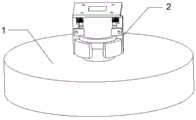
图7为可拆卸电池换接充电装置的示意图。FIG. 7 is a schematic diagram of a detachable battery swap charging device.
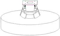
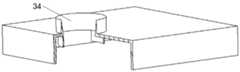
图8为可拆卸电池换接充电装置充电平台的示意图。FIG. 8 is a schematic diagram of a charging platform for a detachable battery swapping charging device.
图9为可拆卸电池换接充电装置充电平台的示意图。FIG. 9 is a schematic diagram of a charging platform for a detachable battery swapping charging device.
图10为可拆卸电池换接充电装置充电车的示意图。FIG. 10 is a schematic diagram of a charging vehicle with a detachable battery swapping charging device.
图11为可拆卸电池换接充电装置充电平台卡爪处于初始位置的俯视图。FIG. 11 is a top view of the charging platform claw of the detachable battery swap charging device in the initial position.
图12为可拆卸电池换接充电装置充电平台卡爪处于收拢状态的俯视图。FIG. 12 is a top view of the charging platform claw of the detachable battery swap charging device in a folded state.
图13为可拆卸电池换接充电装置回转台的示意图。FIG. 13 is a schematic diagram of the turntable of the detachable battery swapping and charging device.
图14为可拆卸电池换接充电装置充电头的示意图。FIG. 14 is a schematic diagram of the charging head of the detachable battery swapping charging device.
图15为可拆卸电池换接充电装置充电头的俯视图。FIG. 15 is a top view of the charging head of the detachable battery swap charging device.
图16为无人机电池换接充电系统的流程图。Figure 16 is a flow chart of the UAV battery swap charging system.
可拆卸电池装置(1),电池连接装置(2),电池(3),电池仓(4),第一接头(5),连接板(6),第二接头(7),夹紧装置(8),同心圆槽(9),压簧片(10),斜坡(11),铜极(12),复位弹簧(13),夹手(14),充电平台(15),充电车(16),回转台(17),充电头(18),卡爪(19),抬升杆(20),摄像头(21),蓄电池(23),视觉识别模块(24),车轮(25),电机(26),卡爪臂(27),卡爪末端(28),接盘(29),充电臂(30),圆形通孔(31),通孔(32),中心圆柱(33),喇叭口(34),螺钉(22)。Detachable battery device (1), battery connecting device (2), battery (3), battery compartment (4), first connector (5), connecting plate (6), second connector (7), clamping device ( 8), concentric circular groove (9), pressure spring (10), slope (11), copper pole (12), return spring (13), gripper (14), charging platform (15), charging car (16) ), turntable (17), charging head (18), jaws (19), lifting rod (20), camera (21), battery (23), visual recognition module (24), wheels (25), motor ( 26), claw arm (27), claw end (28), connecting plate (29), charging arm (30), circular through hole (31), through hole (32), central cylinder (33), bell mouth (34), screw (22).
具体实施方式Detailed ways
下面结合附图和具体实施例对本发明作进一步详细的说明。The present invention will be described in further detail below with reference to the accompanying drawings and specific embodiments.
如图5、6所示,本发明提供的可拆卸电池包含可拆卸电池装置(1)以及电池连接装置(2),可拆卸电池装置(1)包含电池(3)、电池仓(4)以及第一接头(5),电池连接装置包含连接板(6)、第二接头(7)以及夹紧装置(8)。As shown in Figures 5 and 6, the removable battery provided by the present invention includes a removable battery device (1) and a battery connection device (2), and the removable battery device (1) includes a battery (3), a battery compartment (4) and The first connector (5), the battery connecting device comprises a connecting plate (6), a second connector (7) and a clamping device (8).
如图1、2所示,电池(3)放置于电池仓(4)仓体内部,第一接头(5)底部与电池仓(4)仓体外部相连,电池仓(4)为圆盘状,第一接头(5)为圆柱状,第一接头(5)处于电池仓(4)正中位置,第一接头(5)顶部含有同心圆槽(9),同心圆槽(9)的数量为三个,同心圆槽(9)中,处于第一接头(5)顶部最外侧的同心圆槽(9)深度小于处于内侧的两个同心圆槽(9),第一接头(5)顶部内侧的两个同心圆槽(9)中分别装有压簧片(10),第一接头(5)顶部内侧的两个同心圆槽(9)中分别装有一个压簧片(10),第一接头(5)顶部内侧的两个同心圆槽(9)中的压簧片(10)呈180°相对放置,第一接头(5)顶部内侧的两个同心圆槽(9)中的压簧片(10)通过导线分别与电池(3)的正负极相连,第一接头(5)外侧设有斜坡(11)。As shown in Figures 1 and 2, the battery (3) is placed inside the battery compartment (4), the bottom of the first connector (5) is connected to the outside of the battery compartment (4), and the battery compartment (4) is disc-shaped , the first connector (5) is cylindrical, the first connector (5) is in the center of the battery compartment (4), the top of the first connector (5) contains concentric circular grooves (9), and the number of concentric circular grooves (9) is Three, among the concentric circular grooves (9), the depth of the outermost concentric circular groove (9) at the top of the first joint (5) is less than the depth of the two concentric circular grooves (9) located on the inner side, and the inner side of the top of the first joint (5) The two concentric circular grooves (9) are respectively equipped with a pressure spring (10), and the two concentric circular grooves (9) on the inside of the top of the first joint (5) are respectively equipped with a pressure spring (10). The pressure springs (10) in the two concentric circular grooves (9) on the inner side of the top of a joint (5) are placed opposite to each other at 180°, and the pressure springs (10) in the two concentric circular grooves (9) on the inner side of the top of the first joint (5) The reeds (10) are respectively connected with the positive and negative electrodes of the battery (3) through wires, and a slope (11) is provided on the outside of the first joint (5).
如图3、4所示,第二接头(7)顶部与连接板(6)相连,第二接头(7)为圆柱状,第二接头(7)内部镂空,第二接头(7)外壁厚度与第一接头(5)顶部最外侧的同心圆槽(9)的直径相等,第二接头(7)内部与连接板(6)相连处含有同心圆槽(9),同心圆槽(9)的数量为两个,第二接头(7)内部的两个同心圆槽(9)分别固定有铜极(12),第二接头(7)内部的两个同心圆槽(9)分别固定有一个铜极(12),铜极(12)为圆环状,铜极(12)位置与压簧片(10)位置啮合,铜极(12)正负极与压簧片(10)正负极啮合,铜极(12)分别与导线相连,铜极(12)分别与一根导线相连,铜极(12)中,内侧铜极(12)连接的导线穿过连接板,外侧铜极(12)连接的导线方向与内侧铜极(12)连接的导线方向一致,夹紧装置(8)包含复位弹簧(13)以及夹手(14),复位弹簧(13)与夹手(14)相连,夹手(14)的数量为两个,夹手(14)通过螺钉(22)连接于第二接头(7)外侧,夹手(14)呈180°相对放置,夹手(14)与第一接头(5)外侧的斜坡(11)啮合。As shown in Figures 3 and 4, the top of the second joint (7) is connected to the connecting plate (6), the second joint (7) is cylindrical, the inside of the second joint (7) is hollowed out, and the thickness of the outer wall of the second joint (7) The diameter of the outermost concentric groove (9) at the top of the first joint (5) is equal to that of the second joint (7), and the inner part of the second joint (7) connected with the connecting plate (6) contains a concentric groove (9). The concentric groove (9) The number is two, the two concentric circular grooves (9) inside the second joint (7) are respectively fixed with copper poles (12), and the two concentric circular grooves (9) inside the second joint (7) are respectively fixed with A copper pole (12), the copper pole (12) is annular, the position of the copper pole (12) is engaged with the position of the pressure spring (10), and the positive and negative poles of the copper pole (12) are connected to the positive and negative poles of the pressure spring (10). The poles are meshed, and the copper poles (12) are respectively connected with the wires, and the copper poles (12) are respectively connected with a wire. 12) The direction of the connected wire is the same as the direction of the wire connected to the inner copper pole (12). The clamping device (8) includes a return spring (13) and a clamping hand (14). The restoring spring (13) is connected to the clamping hand (14). , the number of the gripping hands (14) is two, the gripping hands (14) are connected to the outer side of the second joint (7) through the screws (22), the gripping hands (14) are placed opposite to each other at 180°, and the gripping hands (14) are connected to the second joint (7). A ramp (11) on the outside of a joint (5) engages.
如图7、8、10所示,本发明提供的可拆卸电池换接充电装置包含充电平台(15)、充电车(16)、回转台(17)、充电头(18)、卡爪(19)以及抬升杆(20),可拆卸电池换接充电装置包含充电平台(15)以及充电车(16),充电平台(15)内部设置有回转台(17)以及充电头(18),充电平台(15)顶部设置有喇叭口(34)、卡爪(19)以及摄像头(21),充电车(16)内部设置有抬升杆(20)以及蓄电池(23),充电车底部设置有车轮(25)、电机(26)。As shown in Figures 7, 8, and 10, the detachable battery swapping and charging device provided by the present invention comprises a charging platform (15), a charging cart (16), a turntable (17), a charging head (18), and a clamping claw (19). ) and a lifting rod (20), the detachable battery swapping and charging device includes a charging platform (15) and a charging cart (16), the charging platform (15) is provided with a turntable (17) and a charging head (18), and the charging platform (15) A bell mouth (34), a clamping claw (19) and a camera (21) are arranged at the top, a lift rod (20) and a battery (23) are arranged inside the charging vehicle (16), and wheels (25) are arranged at the bottom of the charging vehicle ), motor (26).
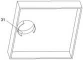
如图8、9所示,充电平台(15)顶部有一圆形通孔(31),底部镂空,圆形通孔(31)向充电平台(15)底部延伸,延伸部分最底端接近充电平台(15)内部的回转台(17),圆形通孔(31)的延伸部分有对称缺口,位于充电平台(15)位于充电车(16)顶部,充电平台(15)底面即为充电车(16)顶面,喇叭口(34)设置于圆形通孔(31)上方,喇叭口(34)直径大于电池仓(4)直径。As shown in Figures 8 and 9, the top of the charging platform (15) has a circular through hole (31), the bottom is hollowed out, the circular through hole (31) extends to the bottom of the charging platform (15), and the bottom end of the extended part is close to the charging platform (15) The inner turntable (17), the extension of the circular through hole (31) has a symmetrical notch, and is located on the charging platform (15) on the top of the charging vehicle (16), and the bottom surface of the charging platform (15) is the charging vehicle ( 16) On the top surface, the bell mouth (34) is arranged above the circular through hole (31), and the diameter of the bell mouth (34) is larger than the diameter of the battery compartment (4).
如图11、12所示,卡爪(19)的数量为两个,卡爪(19)设置于喇叭口(34)顶部两侧,卡爪(19)呈180°相对放置,卡爪(19)分为卡爪臂(27)与卡爪末端(28),卡爪臂(27)为圆环形,卡爪末端(28)为一个半圆环,卡爪臂(27)为外径等于喇叭口(34)顶部外径的圆环形,卡爪(19)的初始位置是卡爪臂(27)与喇叭口(34)顶部外径在水平面上的投影重合处,卡爪(19)收拢时,两个卡爪末端(28)形成一个整圆,卡爪(19)收拢时,两个卡爪末端(28)形成一个直径等于第二接头(7)的整圆。As shown in Figures 11 and 12, the number of the claws (19) is two, the claws (19) are arranged on both sides of the top of the bell mouth (34), the claws (19) are placed opposite to each other at 180°, and the claws (19) ) is divided into a claw arm (27) and a claw end (28), the claw arm (27) is a circular ring, the claw end (28) is a semi-circle, and the claw arm (27) has an outer diameter equal to The outer diameter of the top of the bell mouth (34) is circular, the initial position of the claw (19) is the projection of the claw arm (27) and the top outer diameter of the bell mouth (34) on the horizontal plane, and the claw (19) When folded, the two jaw ends (28) form a full circle, and when the jaws (19) are folded, the two jaw ends (28) form a full circle with a diameter equal to the second joint (7).
如图7、10、13、14、15所示,回转台(17)位于喇叭口(34)底部下方,回转台(17)有若干个完全相同的接盘(29),接盘(29)直径等于电池仓(4)直径,接盘(29)底部有开有一个直径小于接盘(29)本身的通孔(32),回转台(17)的其中一个接盘(29)正对喇叭口(34),充电头(18)位于回转台(17)顶部正上方,充电头(18)与回转台(17)以中心圆柱(33)相连,回转台(17)可绕中心圆柱(33)旋转,充电头(18)可绕中心圆柱(33)上下移动,充电头(18)有若干个充电完全相同的充电臂(30),充电臂(30)的数量比接盘(29)数量少一个,充电臂(30)分别对应除正对喇叭口(34)外的其余接盘(29),充电臂(30)末端结构与第二接头(7)底部结构、大小相同,含有两个同心圆槽(9)和两个铜极(12),充电臂(30)上的铜极(12)通过导线与蓄电池(23)相连,摄像头(21)设置于充电平台(15)顶部正中央,抬升杆(20)正对圆形通孔(31),抬升杆(20)直径小于通孔(32)直径。As shown in Figures 7, 10, 13, 14, and 15, the turntable (17) is located below the bottom of the bell mouth (34). The diameter of the battery compartment (4), the bottom of the receiving plate (29) has a through hole (32) with a diameter smaller than that of the receiving plate (29) itself, and one of the receiving plates (29) of the turntable (17) is facing the bell mouth (34), The charging head (18) is located just above the top of the turntable (17). The charging head (18) is connected to the turntable (17) by a central cylinder (33). The turntable (17) can rotate around the central cylinder (33). (18) It can move up and down around the central cylinder (33). The charging head (18) has several charging arms (30) that are completely charged. 30) Corresponding to the other connecting plates (29) except the bell mouth (34) facing each other, the end structure of the charging arm (30) is the same as the bottom structure and size of the second connector (7), including two concentric circular grooves (9) and Two copper poles (12), the copper poles (12) on the charging arm (30) are connected to the battery (23) through wires, the camera (21) is arranged in the center of the top of the charging platform (15), and the lifting rod (20) is located in the center of the top of the charging platform (15). For the circular through hole (31), the diameter of the lifting rod (20) is smaller than the diameter of the through hole (32).
本发明提供的无人机电池换接充电系统包含上述可拆卸电池以及可拆卸电池换接充电装置,无人机电池换接充电系统还包含飞行控制系统、装置控制系统,飞行控制系统设置于无人机内部,装置控制系统设置于可拆卸电池换接充电装置内部。飞行控制系统包含陀螺仪、卫星定位模块以及控制电路。陀螺仪可感知无人机飞行姿势,卫星定位模块可控制无人机悬停水平位置及高度。装置控制系统包含视觉识别模块(24)、运动控制系统、电池换接充电控制系统。视觉识别模块(24)可识别无人机位置,运动控制系统可控制可拆卸电池换接充电装置外部运动,电池换接充电控制系统可控制可拆卸电池换接充电装置内部运作。The UAV battery swap charging system provided by the present invention includes the above-mentioned detachable battery and the detachable battery swap charging device. The UAV battery swap charging system also includes a flight control system and a device control system. Inside the man-machine, the device control system is set inside the detachable battery swapping and charging device. The flight control system includes a gyroscope, a satellite positioning module and a control circuit. The gyroscope can sense the flying posture of the UAV, and the satellite positioning module can control the horizontal position and height of the UAV hovering. The device control system includes a visual recognition module (24), a motion control system, and a battery swap charging control system. The visual recognition module (24) can identify the position of the drone, the motion control system can control the external movement of the detachable battery swapping and charging device, and the battery swapping and charging control system can control the internal operation of the detachable battery swapping and charging device.
实施例Example
下面以无人机为例,具体阐述本发明可拆卸电池、可拆卸电池换接充电装置以及无人机电池换接充电系统的实施方法:The following takes the drone as an example to specifically describe the implementation method of the detachable battery, the detachable battery swapping and charging device, and the drone battery swapping and charging system of the present invention:
(1)在无人机底部安装本发明的可拆卸电池,并于可拆卸电池电池仓4底部设置特殊图案,可拆卸电池铜极12通过导线将电池仓4内电池3的能源供给无人机;(1) Install the detachable battery of the present invention at the bottom of the drone, and set a special pattern on the bottom of the
(2)无人机起飞,卫星定位模块可大致记录无人机起始位置;(2) The UAV takes off, and the satellite positioning module can roughly record the starting position of the UAV;
(3)无人机失去遥控器信号或接收到遥控器一键返航指令,无人机内部的飞行控制系统控制无人机自动返航至起始位置上空,并开始缓缓下降;(3) The drone loses the remote control signal or receives a one-key return command from the remote control. The flight control system inside the drone controls the drone to automatically return to the starting position and start to descend slowly;
(4)无人机返航至起始位置,可拆卸电池换接充电装置上的摄像头21捕捉、拍摄电池仓4底部的特殊图案,并传送至可拆卸电池换接充电装置内部的视觉识别模块24;(4) The drone returns to the starting position, and the
(5)可拆卸电池换接充电装置内部的运动控制系统控制可拆卸电池换接充电装置通过电机26催动车轮25进行移动,确保喇叭口34在无人机电池仓4正下方;(5) The motion control system inside the detachable battery swapping and charging device controls the detachable battery swapping and charging device to drive the wheel 25 to move through the motor 26, to ensure that the
(6)可拆卸电池换接充电装置内部的视觉识别模块24根据图片可判断无人机可拆卸电池装置1是否已落入喇叭口34内;(6) The visual recognition module 24 inside the detachable battery swapping and charging device can judge whether the
(7)可拆卸电池换接充电装置内部的电池拆换、充电控制系统驱动卡爪19工作,将复位弹簧13压缩,可拆卸电池的夹手14松开,电池顺着喇叭口34落入接盘中;(7) The detachable battery is replaced and the battery inside the charging device is replaced and replaced, and the charging control system drives the claw 19 to work, compresses the
(8)充电头18向上移动,回转台17旋转一定的角度,充电头18向下移动继续充电,电源为蓄电池23,抬升杆20将新的电池抬升至无人机下方,卡爪19归位,复位弹簧使电池的夹手再次夹紧电池,拆换过程完成,无人机可再次工作。(8) The charging
虽然本发明已以较佳实施例公开如上,但其并非用以限定本发明,任何熟悉此技术的人,在不脱离本发明的精神和范围内,都可做各种的改动与修饰,因此本发明的保护范围应该以权利要求书所界定的为准。Although the present invention has been disclosed above with preferred embodiments, it is not intended to limit the present invention. Anyone who is familiar with this technology can make various changes and modifications without departing from the spirit and scope of the present invention. Therefore, The protection scope of the present invention should be defined by the claims.
Claims (5)
Translated fromChinesePriority Applications (1)
| Application Number | Priority Date | Filing Date | Title |
|---|---|---|---|
| CN201810301956.3ACN108528745B (en) | 2018-04-04 | 2018-04-04 | A UAV battery swap charging system |
Applications Claiming Priority (1)
| Application Number | Priority Date | Filing Date | Title |
|---|---|---|---|
| CN201810301956.3ACN108528745B (en) | 2018-04-04 | 2018-04-04 | A UAV battery swap charging system |
Publications (2)
| Publication Number | Publication Date |
|---|---|
| CN108528745A CN108528745A (en) | 2018-09-14 |
| CN108528745Btrue CN108528745B (en) | 2020-02-18 |
Family
ID=63483245
Family Applications (1)
| Application Number | Title | Priority Date | Filing Date |
|---|---|---|---|
| CN201810301956.3AActiveCN108528745B (en) | 2018-04-04 | 2018-04-04 | A UAV battery swap charging system |
Country Status (1)
| Country | Link |
|---|---|
| CN (1) | CN108528745B (en) |
Families Citing this family (7)
| Publication number | Priority date | Publication date | Assignee | Title |
|---|---|---|---|---|
| TWI682573B (en)* | 2018-11-08 | 2020-01-11 | 瑞軒科技股份有限公司 | Battery assembly, system for assembly and disassembly of battery and method thereof |
| CN110525243A (en)* | 2019-09-06 | 2019-12-03 | 北京有感科技有限责任公司 | Unmanned plane wireless charging device |
| CN110758128A (en)* | 2019-11-04 | 2020-02-07 | 中国北方车辆研究所 | Vehicle-mounted unmanned vehicle charging system |
| CN110979091B (en)* | 2019-12-24 | 2023-03-31 | 江南大学 | Unmanned aerial vehicle battery replacement system |
| CN111267790B (en)* | 2020-02-11 | 2021-07-27 | 江南大学 | A kind of UAV battery quick change system |
| CN111267791B (en)* | 2020-02-11 | 2021-04-30 | 江南大学 | A kind of UAV battery quick change device |
| CN112659961B (en)* | 2020-11-17 | 2022-11-25 | 重庆峘能电动车科技有限公司 | Electricity vending machine and electricity exchanging station |
Family Cites Families (6)
| Publication number | Priority date | Publication date | Assignee | Title |
|---|---|---|---|---|
| CN201004180Y (en)* | 2007-01-26 | 2008-01-09 | 青岛天骄无人机遥感技术有限公司 | UAV Attitude Control System |
| CN102424111B (en)* | 2012-01-06 | 2014-05-07 | 厦门大学 | Flexible saucer-shaped aircraft |
| CN102902276A (en)* | 2012-10-12 | 2013-01-30 | 大连理工大学 | Flying control system based on polarized light sensor |
| CN105278541B (en)* | 2015-09-02 | 2018-08-17 | 盐城智博科技有限公司 | A kind of aircraft auxiliary landing control method and system |
| CN106483979A (en)* | 2016-12-19 | 2017-03-08 | 重庆信首科技有限公司 | A kind of unmanned aerial vehicle control system for land for growing field crops bird repellent |
| CN206984418U (en)* | 2017-05-27 | 2018-02-09 | 辛亚行 | A kind of vehicle-mounted unmanned aerial vehicle landing platform |
- 2018
- 2018-04-04CNCN201810301956.3Apatent/CN108528745B/enactiveActive
Also Published As
| Publication number | Publication date |
|---|---|
| CN108528745A (en) | 2018-09-14 |
Similar Documents
| Publication | Publication Date | Title |
|---|---|---|
| CN108528745B (en) | A UAV battery swap charging system | |
| CN108515866B (en) | Detachable battery switching charging device | |
| CN110667870B (en) | Unmanned aerial vehicle is energy autonomous base station of independently taking off and land trading battery based on solar energy power supply | |
| CN105857593B (en) | A four-rotor multi-purpose flying robot | |
| CN111056032B (en) | An unmanned ship-borne unmanned aerial vehicle charging and lifting system and its realization method | |
| CN104898690A (en) | Rotor unmanned aerial vehicle self journey-continuing realization method based on APM platform | |
| CN209080161U (en) | It is a kind of for launching the unmanned plane grabbing device of miniature photovoltaic clean robot | |
| CN106873623A (en) | A kind of unmanned plane is quickly independently continued a journey system and method | |
| CN106218912A (en) | UAV battery automatic exchange, data transmission and fault detection platform | |
| CN204096090U (en) | A kind of Unmanned Aircraft Systems (UAS) | |
| CN111267790B (en) | A kind of UAV battery quick change system | |
| CN108033031A (en) | Field unmanned flight's platform with solar charging device | |
| CN106218873A (en) | The anti-protection structure of crashing of a kind of unmanned plane | |
| CN109774521B (en) | UAV docking system | |
| CN211390988U (en) | Airport, airborne charging device and module and automatic airport and unmanned aerial vehicle | |
| CN110065645A (en) | High-precision UAV Flight Control System | |
| CN110979091B (en) | Unmanned aerial vehicle battery replacement system | |
| CN111038326B (en) | Rotatory device of changing of unmanned aerial vehicle battery | |
| CN111404239A (en) | A porous charging panel of antiskid for unmanned aerial vehicle descending charges | |
| CN112278307B (en) | Unmanned aerial vehicle positioning, clamping and charging mechanism, control method and hangar | |
| CN113479107B (en) | A long-lasting battery-replacing UAV in the air and its use method | |
| CN108448040B (en) | a removable battery | |
| CN207759063U (en) | Field unmanned flight's platform with solar charging device | |
| CN211642603U (en) | Many rotor unmanned aerial vehicle remove power supply unit based on vision | |
| CN118529293A (en) | A drone capable of replacing power in the air and a method of using the drone |
Legal Events
| Date | Code | Title | Description |
|---|---|---|---|
| PB01 | Publication | ||
| PB01 | Publication | ||
| SE01 | Entry into force of request for substantive examination | ||
| SE01 | Entry into force of request for substantive examination | ||
| GR01 | Patent grant | ||
| GR01 | Patent grant |