CN108517799B - A kind of traffic control method of road merging area using lifting speed bumps - Google Patents
A kind of traffic control method of road merging area using lifting speed bumpsDownload PDFInfo
- Publication number
- CN108517799B CN108517799BCN201810317857.4ACN201810317857ACN108517799BCN 108517799 BCN108517799 BCN 108517799BCN 201810317857 ACN201810317857 ACN 201810317857ACN 108517799 BCN108517799 BCN 108517799B
- Authority
- CN
- China
- Prior art keywords
- vehicle
- road
- speed
- main
- merging
- Prior art date
- Legal status (The legal status is an assumption and is not a legal conclusion. Google has not performed a legal analysis and makes no representation as to the accuracy of the status listed.)
- Expired - Fee Related
Links
- 238000000034methodMethods0.000titleclaimsabstractdescription51
- 230000007246mechanismEffects0.000claimsabstractdescription39
- 230000008569processEffects0.000claimsdescription36
- 230000006698inductionEffects0.000claimsdescription16
- 238000009434installationMethods0.000claimsdescription15
- 230000001133accelerationEffects0.000claimsdescription11
- 230000009471actionEffects0.000claimsdescription8
- 239000002985plastic filmSubstances0.000claimsdescription4
- 229920006255plastic filmPolymers0.000claimsdescription4
- 230000001681protective effectEffects0.000claimsdescription4
- 125000004122cyclic groupChemical group0.000claimsdescription3
- 230000009467reductionEffects0.000claimsdescription3
- 230000004044responseEffects0.000claimsdescription3
- 230000033001locomotionEffects0.000description8
- 238000010586diagramMethods0.000description7
- 230000008859changeEffects0.000description5
- 238000006073displacement reactionMethods0.000description5
- 230000005540biological transmissionEffects0.000description4
- 238000001514detection methodMethods0.000description4
- 230000033228biological regulationEffects0.000description3
- 238000003780insertionMethods0.000description3
- 230000037431insertionEffects0.000description3
- 230000001276controlling effectEffects0.000description2
- 230000001934delayEffects0.000description2
- 238000013461designMethods0.000description2
- 206010039203Road traffic accidentDiseases0.000description1
- 238000013475authorizationMethods0.000description1
- 230000009286beneficial effectEffects0.000description1
- 238000011835investigationMethods0.000description1
- 238000002955isolationMethods0.000description1
- 239000002184metalSubstances0.000description1
- 238000012545processingMethods0.000description1
- 238000011897real-time detectionMethods0.000description1
- 238000011084recoveryMethods0.000description1
- 230000001105regulatory effectEffects0.000description1
- 238000005096rolling processMethods0.000description1
- 230000001960triggered effectEffects0.000description1
Images


Classifications
- E—FIXED CONSTRUCTIONS
- E01—CONSTRUCTION OF ROADS, RAILWAYS, OR BRIDGES
- E01F—ADDITIONAL WORK, SUCH AS EQUIPPING ROADS OR THE CONSTRUCTION OF PLATFORMS, HELICOPTER LANDING STAGES, SIGNS, SNOW FENCES, OR THE LIKE
- E01F9/00—Arrangement of road signs or traffic signals; Arrangements for enforcing caution
- E01F9/50—Road surface markings; Kerbs or road edgings, specially adapted for alerting road users
- E01F9/529—Road surface markings; Kerbs or road edgings, specially adapted for alerting road users specially adapted for signalling by sound or vibrations, e.g. rumble strips; specially adapted for enforcing reduced speed, e.g. speed bumps
- E—FIXED CONSTRUCTIONS
- E01—CONSTRUCTION OF ROADS, RAILWAYS, OR BRIDGES
- E01F—ADDITIONAL WORK, SUCH AS EQUIPPING ROADS OR THE CONSTRUCTION OF PLATFORMS, HELICOPTER LANDING STAGES, SIGNS, SNOW FENCES, OR THE LIKE
- E01F13/00—Arrangements for obstructing or restricting traffic, e.g. gates, barricades ; Preventing passage of vehicles of selected category or dimensions
- E01F13/04—Arrangements for obstructing or restricting traffic, e.g. gates, barricades ; Preventing passage of vehicles of selected category or dimensions movable to allow or prevent passage
- E01F13/048—Arrangements for obstructing or restricting traffic, e.g. gates, barricades ; Preventing passage of vehicles of selected category or dimensions movable to allow or prevent passage with obstructing members moving in a translatory motion, e.g. vertical lift barriers, sliding gates
Landscapes
- Engineering & Computer Science (AREA)
- Architecture (AREA)
- Civil Engineering (AREA)
- Structural Engineering (AREA)
- Traffic Control Systems (AREA)
Abstract
Description
Translated fromChinese技术领域technical field
本发明涉及交通信息工程及其控制领域,具体涉及一种利用升降减速带的道路合流区交通控制方法。The invention relates to the field of traffic information engineering and its control, in particular to a traffic control method in a road merging area using a lifting speed bump.
背景技术Background technique
在城市交通系统中,道路合流区域的通行能力是影响道路通行能力的重要因素之一,而在现有城市道路系统之中分合流路口数量众多且无相应交通管理控制设施,这就导致在早、晚高峰期间分合流区交织变道车辆数量增多,使得分合流区成为"瓶颈"从而引发交通拥挤。In the urban traffic system, the traffic capacity of the road junction area is one of the important factors affecting the road traffic capacity. In the existing urban road system, there are a large number of sub-junction intersections and no corresponding traffic management and control facilities, which leads to early . During the evening rush hour, the number of vehicles interweaving and changing lanes in the sub-merging area increases, making the sub-merging area a "bottleneck" and causing traffic congestion.
目前国内针对合流区高峰时实行的"拉链式"交通法规:“在两车道并一车道出现停车排队等候或者缓慢行驶时,左边过一辆车,右边过一辆车,然后左边再过一辆车,反反复复,有序行进。”该法规存在两个不足:The current domestic "zipper-type" traffic regulations for the rush hour in the merging area: "When there are two lanes and one lane waiting in line or when driving slowly, pass a car on the left, a car on the right, and then another car on the left. Cars, repeatedly, and orderly." There are two shortcomings in this regulation:
1)车辆到达合流区之后需要减速瞭望后通过,由此会产生交通延误;1) After the vehicle reaches the merging area, it needs to slow down and look around before passing, which will cause traffic delays;
2)法规应用前提是合流区两条道路都产生了排队,可以实施交替通行,如果有一方没有车辆将产生更大的延误,并且增大另一方向车辆拥挤程度。2) The premise of the application of the regulations is that the two roads in the merging area have queues, and alternate traffic can be implemented. If one side has no vehicles, it will cause greater delays and increase the congestion of vehicles in the other direction.
因此,需要一种基于实时检测数据下的智能控制设施来协助车辆顺利合流。Therefore, an intelligent control facility based on real-time detection data is needed to assist the smooth merging of vehicles.
发明内容SUMMARY OF THE INVENTION
本发明的目的是为了解决合流区交通车流速度慢及秩序混乱的问题,而提出一种利用升降减速带的道路合流区交通控制方法。The purpose of the present invention is to provide a traffic control method in a road merging area using a lift and deceleration belt in order to solve the problems of slow traffic flow and disordered order in the merging area.
一种升降减速带包括:底板、液压装置、平面四杆机构、滑块、减速带主体和导轨;A lift deceleration belt comprises: a base plate, a hydraulic device, a plane four-bar mechanism, a slider, a deceleration belt main body and a guide rail;
在底板表面的一端设置液压装置,液压装置与平面四杆机构连接;在底板表面的另一端设置导轨,滑块与减速带主体下表面的支撑杆连接,滑块沿着导轨上下运动,减速带主体设置在平面四杆机构的上方;A hydraulic device is arranged on one end of the base plate surface, and the hydraulic device is connected with the plane four-bar mechanism; a guide rail is arranged at the other end of the base plate surface, and the slider is connected with the support rod on the lower surface of the main body of the speed bump. The slider moves up and down along the guide rail, and the speed bump The main body is arranged above the plane four-bar mechanism;
减速带主体的下表面设置滚轮导槽,平面四杆机构上设置滚轮装置,滚轮装置与滚轮导槽配合使用,实现平面四杆机构横向移动从而带动减速带主体在滑块的作用下沿导轨上下移动。The lower surface of the main body of the speed bump is provided with a roller guide groove, and the flat four-bar mechanism is provided with a roller device. The roller device is used in conjunction with the roller guide groove to realize the lateral movement of the flat four-bar mechanism to drive the speed bump body to move up and down along the guide rail under the action of the slider. move.
一种利用升降减速带的道路合流区交通控制方法包括以下步骤:A traffic control method in a road merging area using a lift and speed bump includes the following steps:
步骤一:选取合流区主路和辅路安装所述升降减速带的位置、地感线圈位置以及可变限速牌的位置;Step 1: Select the position of the main road and the auxiliary road in the junction area to install the lifting and deceleration belt, the position of the ground sense coil and the position of the variable speed limit sign;
步骤二:在步骤一选取的位置安装所述升降减速带、地感线圈位置以及可变限速牌;Step 2: install the lift deceleration belt, the position of the ground induction coil and the variable speed limit card at the position selected in step 1;
步骤三:根据步骤二安装的升降减速带、地感线圈位置以及可变限速牌对主路和辅路车辆进行控制。Step 3: Control the main road and auxiliary road vehicles according to the lifting speed bumps installed in step 2, the position of the ground sensing coil and the variable speed limit sign.
本发明的有益效果为:The beneficial effects of the present invention are:
地磁线圈检测主路和辅路的速度和到达检测器时间判断车辆到达交织地点,升降减速带根据预计到达时间进行决策,灵活升起减速带和改变限速信息对车辆进行控制。如预计到达时间可使车辆满足插入条件,则系统不采取措施作用车辆。如不满足要求,通过第一组减速带的升起和可变信息板的限速信息变化控制对应主路两车辆拉开间距,控制辅路车辆满足到达空隙时间。在对车辆进行第一次调整后,若车辆未能按照第一次的控制需要进行速度的变化,则对车辆进行二次控制,使其满足预期。The geomagnetic coil detects the speed of the main road and the auxiliary road and the arrival time of the detector to determine the arrival of the vehicle at the intersection. The lifting and deceleration belt makes decisions according to the estimated arrival time, and flexibly raises the deceleration belt and changes the speed limit information to control the vehicle. If the estimated time of arrival allows the vehicle to meet the insertion conditions, the system takes no action to act on the vehicle. If the requirements are not met, the distance between the two vehicles on the corresponding main road is controlled by the rise of the first group of speed bumps and the change of the speed limit information of the variable information board, and the vehicles on the auxiliary road are controlled to meet the arrival time of the gap. After the vehicle is adjusted for the first time, if the vehicle fails to change the speed according to the first control requirement, the vehicle will be controlled a second time to make it meet the expectations.
对于满足车辆插入条件的车辆,可使其在无干扰的情况下正常运行,保持路面通畅,正常实现交汇,而不满足车辆插入条件的一组车辆,使该组车辆在两组设施强制调整后顺利实现交汇,变无序合流为有序合流,可以有效提高交织路段的通行能力,提高通行效率,改善交通路段拥挤堵塞的现象。与现有的无信号控制和交叉通行指示牌相比,本发明所述的控制设施,能够使交织区通行能力提高20%-30%,同时也能够缓解驾驶人员因为交汇而要精神高度集中的驾驶状态,降低在该区域出现交通事故的概率。For vehicles that meet the vehicle insertion conditions, it can run normally without interference, keep the road unobstructed, and realize the intersection normally. For a group of vehicles that do not meet the vehicle insertion conditions, the group of vehicles can be forced to adjust after the two groups of facilities. The smooth realization of the intersection and the change from disorderly convergence to orderly convergence can effectively improve the traffic capacity of the interweaving road section, improve the traffic efficiency, and improve the congestion and congestion of the traffic road section. Compared with the existing non-signal control and cross traffic signs, the control facility of the present invention can increase the traffic capacity of the interweaving area by 20%-30%, and can also alleviate the driver's high concentration due to the intersection. Driving state, reducing the probability of traffic accidents in the area.
附图说明Description of drawings
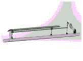
图1为本发明升降减速带示意图;Fig. 1 is the schematic diagram of the lifting deceleration belt of the present invention;
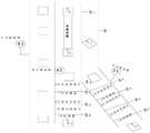
图2为滑块示意图;Figure 2 is a schematic diagram of the slider;
图3为滚轮导槽示意图;Figure 3 is a schematic diagram of a roller guide groove;
图4为升降减速带设计机械结构图;Fig. 4 is the mechanical structure diagram of the design of the lift deceleration belt;
图5为本发明升降减速带侧视图1;Fig. 5 is the side view 1 of the lifting deceleration belt of the present invention;
图6为本发明升降减速带侧视图2;Fig. 6 is the side view 2 of the lifting deceleration belt of the present invention;
图7为本发明升降减速带布设位置示意图;FIG. 7 is a schematic diagram of the arrangement position of the lifting deceleration belt according to the present invention;
图8为本发明控制设施实物3D图;8 is a 3D diagram of a physical object of the control facility of the present invention;
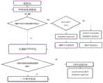
图9为本发明升降减速带控制流程图。Fig. 9 is the control flow chart of the lifting and deceleration belt of the present invention.
具体实施方式Detailed ways
具体实施方式一:一种升降减速带包括:底板1、液压装置2、平面四杆机构3、定位滑块4、减速带主体5和导轨6;Embodiment 1: A lift deceleration belt includes: a bottom plate 1, a hydraulic device 2, a plane four-
在底板1表面的一端设置液压装置2,液压装置2与平面四杆机构3连接;在底板1表面的另一端设置导轨6,定位滑块4与减速带主体5下表面的支撑杆连接,定位滑块4沿着导轨6上下运动,减速带主体5设置在平面四杆机构3的上方;A hydraulic device 2 is arranged at one end of the surface of the base plate 1, and the hydraulic device 2 is connected with the plane four-
减速带主体5的下表面设置滚轮导槽5-1,平面四杆机构3上设置滚轮3-1,滚轮3-1与滚轮导槽5-1配合使用,实现平面四杆机构3横向移动从而带动减速带主体(5)在定位滑块4的作用下沿导轨6上下移动。该智能升降减速带(本发明升降减速带)设计参数要求如下:A roller guide groove 5-1 is arranged on the lower surface of the

本发明升降减速带的工作原理:The working principle of the lifting speed reduction belt of the present invention:
如图1和图4所示,本发明包括底板1、液压装置2、平面四杆机构3、定位滑块4、减速带主体5、导轨6以及控制装置(图中未标出):减速带主体5置于路面以下,平面四杆机构3以上,液压装置2置于平面四杆机构3与定位滑块4之间,减速带主体5上设有橡胶减速带,橡胶减速带平时与路面平齐,必要时升起,控制装置与液压装置2相连。As shown in Figures 1 and 4, the present invention includes a base plate 1, a hydraulic device 2, a plane four-
传动机构以及支撑机构为平面四杆机构,由底板1、液压装置2、平面四杆机构3、定位滑块4和减速带主体5、导轨6组成。在平面四杆机构右侧加有滚轮滑块机构用以限制平面四杆机构的水平方向运动,为了满足运动关系,在与减速带主体5连接的每个低副处均加有滚轮滑块装置。The transmission mechanism and the supporting mechanism are a plane four-bar mechanism, which is composed of a base plate 1, a hydraulic device 2, a plane four-
控制装置用于控制液压装置的运动。The control device is used to control the movement of the hydraulic device.
升降减速带在工作时,传感器测得的车速会反馈给控制装置,控制装置控制液压装置2的运动,液压缸运动实现对平面四杆机构的运动的控制,进而实现对减速带的升降控制。液压缸顶起时,平面四杆机构3逆时针旋转,由于定位滑块4的作用,减速带主体5垂直起升,带动减速带上升;液压缸降下时,平面四杆机构3顺时针旋转,由于定位滑块4的作用,减速带主体5垂直下降,带动减速带下降。When the lifting speed bump is working, the vehicle speed measured by the sensor will be fed back to the control device, which controls the movement of the hydraulic device 2, and the movement of the hydraulic cylinder realizes the control of the movement of the plane four-bar mechanism, thereby realizing the lifting control of the speed bump. When the hydraulic cylinder is jacked up, the plane four-
为了限制减速带水平方向的位移,本发明采用定位滑块4,并辅助设计了滚轮导槽5-1(如图3所示)和滚轮3-1来补偿平面四杆机构3的水平位移。滚轮导槽5-1的结构如下图所示。减速带工作时,定位滑块4被导轨6顶住,使得平面四杆机构3的水平位移受阻。同时,滚轮3-1连接在平面四杆机构3上,滚轮可在连接在减速带主体5上的5-1滚轮导槽内滚动,由此可补偿减速带在水平方向上的位移,使整个系统的自由度为1,实现垂直起降。In order to limit the horizontal displacement of the deceleration belt, the present invention adopts the
在补偿平面四杆机构3的水平位移时,不仅要靠滑动导槽5-1及滚轮3-1的配合,还需要用到定位滑块4和导轨6的配合滚动动才行。定位滑块4在导轨6上滚动的示意图如图2所示。When compensating the horizontal displacement of the plane four-
具体实施方式二:本实施方式与具体实施方式一不同的是:减速带主体5的上表面为向上突起曲面,且减速带主体5的横截面为劣弧弓形状。底板1的长度大于减速带主体5的长度。Embodiment 2: The difference between this embodiment and Embodiment 1 is that the upper surface of the
其它步骤及参数与具体实施方式一相同。Other steps and parameters are the same as in the first embodiment.
具体实施方式三:本实施方式与具体实施方式一或二不同的是:所述减速带主体5的长度为道路单车道的宽度。Embodiment 3: The difference between this embodiment and Embodiment 1 or 2 is that the length of the speed bump
其它步骤及参数与具体实施方式一或二相同。Other steps and parameters are the same as in the first or second embodiment.
具体实施方式四:本实施方式与具体实施方式一至三之一不同的是:所述减速带主体5的宽度为30cm。Embodiment 4: The difference between this embodiment and one of Embodiments 1 to 3 is that the width of the speed bump
其它步骤及参数与具体实施方式一至三之一相同。Other steps and parameters are the same as one of the first to third embodiments.
具体实施方式五:本实施方式与具体实施方式一至四之一不同的是:所述液压装置2外部设置保护装置。Embodiment 5: The difference between this embodiment and one of Embodiments 1 to 4 is that a protection device is provided outside the hydraulic device 2 .
其它步骤及参数与具体实施方式一至四之一相同。Other steps and parameters are the same as one of the first to fourth embodiments.
具体实施方式六:利用升降减速带的道路合流区交通控制方法包括以下步骤:Embodiment 6: The traffic control method in the road merging area using the lifting and deceleration belt includes the following steps:
步骤一:选取合流区主路和辅路安装所述升降减速带的位置、地感线圈位置以及可变限速牌的位置;Step 1: Select the position of the main road and the auxiliary road in the junction area to install the lifting and deceleration belt, the position of the ground sense coil and the position of the variable speed limit sign;
步骤二:在步骤一选取的位置安装所述升降减速带、地感线圈以及可变限速牌;Step 2: Install the lift deceleration belt, ground sense coil and variable speed limit card at the position selected in step 1;
步骤三:根据步骤二安装的升降减速带、地感线圈以及可变限速牌对主路和辅路车辆进行控制。如图9所示。Step 3: Control the main road and auxiliary road vehicles according to the lifting speed bumps, ground induction coils and variable speed limit plates installed in step 2. As shown in Figure 9.
具体实施方式七:本实施方式与具体实施方式六不同的是:如图7和图8所示,所述步骤一中选取合流区主路和辅路安装所述升降减速带的位置、地感线圈位置以及可变限速牌的位置的具体过程为:Embodiment 7: The difference between this embodiment and
在主路和辅路上分别设置两个地感线圈和两个升降减速带;Two ground induction coils and two lift deceleration belts are respectively set on the main road and the auxiliary road;
设置车辆合流位置为S1;Set the vehicle merging position as S1 ;
以车辆前进方向为正方向,在主路和辅路上车辆经过的第二处升降减速带的位置为S2,在主路和辅路S2位置分别设置1个可变限速牌;Taking the forward direction of the vehicle as the positive direction, the position of the second lifting and deceleration belt on the main road and the auxiliary road is S2 , and a variable speed limit sign is set at the position of S2 on the main road and the auxiliary road respectively;
S2位置确定的具体过程为:The specific process of S2 position determination is as follows:
主路车辆经过该系统减速加速(加速减速)调整后,以满足成功合流的空间条件。如果车辆在离开该系统至合流位置S1期间擅自变速,则会使得合流无法按要求完成,因此S1S2为使车辆经过系统调整后,主路合流速度保持匀速行驶的最小距离,即:The main road vehicle is adjusted by the system to decelerate and accelerate (accelerate and decelerate) to meet the space conditions for successful merging. If the vehicle shifts without authorization during the period from leaving the system to the merging position S1 , the merging cannot be completed as required, so S1 S2 is the minimum distance for the vehicle to keep the main road merging speed at a constant speed after the system is adjusted, namely:
S1S2=vmin×tmaxS1 S2 =vmin ×tmax
其中vmin为主路高峰小时合流区入口前行车速度最小值,tmax为车辆经过限速牌保持匀速的最大时间;S1S2为S1和S2之间的距离;Among them, vmin is the minimum value of the vehicle speed before the entrance of the merging area of the main road during peak hours, tmax is the maximum time for the vehicle to pass the speed limit sign and maintain a constant speed; S1 S2 is the distance between S1 and S2 ;
以车辆前进方向为正方向,在主路和辅路上车辆经过的第二处地感线圈的位置为S3,第S3位置确定的具体过程为:Taking the forward direction of the vehicle as the positive direction, the position of the second ground sensing coil passed by the vehicle on the main road and the auxiliary road is S3 , and the specific process of determining the S3 position is:
2号检测器的安装位置以地磁传感器检测速度的安装位置公式为例:The installation position of the No. 2 detector takes the installation position formula of the detection speed of the geomagnetic sensor as an example:
S2S3=X+13.9tsS2 S3 =X+13.9ts
其中ts为处理器的响应时间和升降减速带运行时间;S2S3为S2和S3之间的距离;X是车辆速度检测器安装视距;Where ts is the response time of the processor and the running time of the lifting and deceleration belt; S2 S3 is the distance between S2 and S3 ; X is the vehicle speed detector installation line of sight;
以车辆前进方向为正方向,在主路和辅路上车辆经过的第一处升降减速带的位置为S4,在辅路S4位置设置1个可变限速牌;Taking the forward direction of the vehicle as the positive direction, the position of the first lift and deceleration belt that the vehicle passes through on the main road and the auxiliary road is S4 , and a variable speed limit sign is set at the position of S4 on the auxiliary road;
主路车辆经过1号强制变速区变速之后需要调整速度。所以司机在通过1号变强制速区后应看到2号变速区旁的限速装置,故S2S4之间的距离应小于最大行车速度下的视距,即:Vehicles on the main road need to adjust their speed after passing through the No. 1 forced transmission zone. Therefore, the driver should see the speed limiter next to the No. 2 transmission area after passing through the No. 1 transmission speed zone, so the distance between S2 S4 should be smaller than the sight distance at the maximum driving speed, namely:
S4位置确定的具体过程为:The specific process of determining the position of S4 is as follows:
S2S4≤120(m)S2 S4 ≤120(m)
其中m为单位米。where m is the unit of meter.
除此之外S3S4还应使得车辆在到达2号检测器之间能够完成速度恢复过程,即:In addition, S3 S4 should also enable the vehicle to complete the speed recovery process before reaching the No. 2 detector, namely:

其中vmax为道路限速值,S2S4为S2和S4之间的距离,S3S4为S3和S4之间的距离;Where vmax is the road speed limit value, S2 S4 is the distance between S2 and S4 , and S3 S4 is the distance between S3 and S4 ;
以车辆前进方向为正方向,在主路和辅路上车辆经过的第一处地感线圈的位置为S5,第S5位置确定的具体过程为:Taking the forward direction of the vehicle as the positive direction, the position of the first ground induction coil that the vehicle passes through on the main road and the auxiliary road is S5 , and the specific process for determining the S5th position is:
类比S2S3,S3S4应取两者最大值,即:Analogy S2 S3 , S3 S4 should take the maximum value of the two, namely:
S4S5≥max(S2S3,S3S4)S4 S5 ≥max(S2 S3 ,S3 S4 )
S4S5为S4和S5之间的距离。S4 S5 is the distance between S4 and S5 .
主路和辅路车辆合流位置S1之间存在一个最小差值;There is a minimum difference between the merging position S1of vehicles on the main road and the auxiliary road;

其中v主为主路调查最大限速值,T为主路和辅路最大限速值下的临界最小间隙。Among them, vis the main road to investigate the maximum speed limit value, and T is the critical minimum clearance under the maximum speed limit value of the main road and auxiliary road.
其它步骤及参数与具体实施方式六相同。Other steps and parameters are the same as in the sixth embodiment.
具体实施方式八:本实施方式与具体实施方式六或七不同的是:所述步骤二中在步骤一选取的位置安装所述升降减速带的具体过程为:Embodiment 8: The difference between this embodiment and
1)在步骤一选取的安装所述升降减速带的位置,将路面切割出与减速带主体5长度和宽度尺寸相同的长方形,并挖深10cm,将底板1固定;1) at the position of the installation of the lift deceleration belt selected in step 1, the road surface is cut out into a rectangle with the same length and width as the deceleration belt
2)用膨胀螺栓将液压装置2和平面四杆机构3固定在底板1上;将导轨6固定在底板1上,将定位滑块4安装在导轨上,将减速带主体5安装在平面四杆机构3的上方;液压装置2安装在有路沿石的一侧;为尽可能保持路面完整性,液压系统装箱置于路边,若有绿化带,则置于绿化带中,若无绿化带,则置于主辅路中间的隔离带上。2) Fix the hydraulic device 2 and the plane four-
3)液压装置2安装保护箱,升降减速带置于上端开口的保护箱中,减速带主体5上方设置带有减速带反光标志的塑胶膜,反光塑胶膜固定在道路上(能满足减速带最大升高高度)。3) A protective box is installed in the hydraulic device 2, the lifting and deceleration belt is placed in the protective box with the upper end opening, and a plastic film with a reflective sign of the deceleration belt is arranged above the
升降减速带如图5和图6所示;The lift deceleration belt is shown in Figure 5 and Figure 6;
其它步骤及参数与具体实施方式六或七相同。Other steps and parameters are the same as in the sixth or seventh embodiment.
具体实施方式九:本实施方式与具体实施方式六至八之一不同的是:所述步骤三中根据步骤二安装的升降减速带、地感线圈位置以及可变限速牌对主路和辅路车辆进行控制的具体过程为:Embodiment 9: This embodiment differs from one of
步骤三一:对主路和辅路车辆进行第一次控制;Step 31: Control the main road and auxiliary road vehicles for the first time;
对辅路的控制过程为:The control process of the auxiliary road is as follows:
在主路和辅路S5位置的第一处地感线圈检测车辆速度,处理器记录车辆到达S5位置的时刻,当主路第一处地感线圈检测到主路第i辆车时处理器判断辅路第一处地感线圈是否检测到第i辆车,若无车辆,则不对主路车辆进行控制;若有车辆,则计算主路和辅路第i辆车预计到达车辆合流位置S1的时间;The vehicle speed is detected by the first ground induction coil at the position S5 of the main road and the auxiliary road, and the processor records the time when the vehicle reaches the position S5. When the first ground induction coil of the main road detects the i- th vehicle on the main road, the processor judges Whether the ith vehicle is detected by the ground induction coil at the first place on the side road, if there is no vehicle, the vehicle on the main road will not be controlled; if there isa vehicle, calculate the estimated time for the ith vehicle on the main road and the side road to arrive at the vehicle merging position S1 ;
计算主路和辅路车辆预计到达车辆合流位置S1的时间的过程为:The processof calculating the time when the main road and auxiliary road vehicles are expected to arrive at the vehicle merging position S1 is as follows:
道路合流区的主路和辅路车辆以速度v从S5行驶,且未采取任何措施控制时,合流前主路和辅路车辆需要先以加速度a减速到合流速度v*,再以合流速度v*匀速通过合流位置S1过程行驶时间t;When the main road and auxiliary road vehicles in the road merging area travel from S5 at speed v, and no control measures are taken, the main road and auxiliary road vehicles need to decelerate at the acceleration a to the merging speed v* before the merging, and then at the merging speed v* Travel time t during the process of passing through the confluence position S1 ata constant speed;

若辅路车辆预计到达车辆合流位置S1的时间大于主路车辆预计到达车辆合流位置S1的时间,则辅路S4位置设置可变限速牌显示限高速信息,辅路S2位置设置可变限速牌显示限低速信息,所述限低速信息为35km~45km每小时(根据实际交通调查确定的);If the time that the vehicle on the side road is expected to arrive at the vehicle merging position S1 is greaterthan the time that the vehicleon the main road is expected to arrive at the vehicle merging position S1,a variable speed limit sign is set at the position of the side road S4 to display the speed limit information, and a variable speed limit sign is set at the position of the side road S2. The speed sign displays the information of the low speed limit, and the low speed limit information is 35km-45km per hour (determined according to the actual traffic investigation);
所述限高速信息的计算过程为:The calculation process of the speed limit information is as follows:
Δhi=ti辅-ti主Δhi = ti auxiliary - ti main

ti辅为辅路第i辆车预计到达车辆合流位置S1的时间,ti主为主路第i辆车预计到达车辆合流位置S1的时间,v'i辅为辅路S5位置的第一处地感线圈检测到第i辆车速度,
若辅路第i辆车预计到达车辆合流位置S1的时间小于主路第i辆车预计到达车辆合流位置S1的时间,则辅路S2位置设置的升降减速带升高;If the estimated time for the i-th vehicle on the side road to arrive at the vehicle merging position S1 is less than the estimated time for the i-th vehicle on the main road to arrive at the vehicle merging position S1 , the lift and deceleration belt set at the side road S2 position is raised;
所述辅路S2位置设置的升降减速带升高的高度具体为:The height of the lift deceleration belt set at the position of the auxiliary road S2 is specifically:

v'i辅=7.03R0.5v'i auxiliary = 7.03R0.5
由
若辅路第i辆车预计到达车辆合流位置S1的时间等于主路第i辆车预计到达车辆合流位置S1的时间,则不采取操作;If the time when the i-th vehicle on the side road is expected to arrive at the vehicle merging position S1 is equal to the time when the i-th vehicle on the main road is expected to arrive at the vehicle merging position S1 , no action is taken;
当辅路第i辆车行驶到第二处检测器安装位置S3时对车辆进行速度检测,将车速与处理器运算得出的合流需要车速进行比对;若车辆在减速控制后速度处于合流需要速度范围值内,则在第二处检测器安装位置S3不进行升高,避免对车辆运行产生干扰,影响合流;若车辆在减速控制后超出速度合流需要速度范围值,则处理器输出高电平信号,触发继电器装置,启动驱动电机转动固定角度,带动升降减速带的减速带主体5升高3cm,对车辆进行惩罚性减速;When the i-th vehicle on the side road travels to the second detector installation position S3, the speedof the vehicle is detected, and the vehicle speed is compared with the required speed of the confluence calculated by the processor; Within the speed range value, the second detector installation positionS3 will not be raised to avoid interference to the vehicle operation and affect the merging; if the vehicle exceeds the speed range required for speed merging after deceleration control, the processor output high The level signal triggers the relay device, starts the drive motor to rotate at a fixed angle, drives the deceleration belt
对主路的控制过程为:The control process for the main road is as follows:
在主路和辅路S5位置的第一处地感线圈检测车辆速度,处理器记录第i个车辆到达S5位置的时刻,当主路第一处地感线圈检测到车辆时处理器判断辅路第一处地感线圈是否检测到车辆,若无车辆,则不对主路车辆进行控制;若有车辆,则当主路S5位置的第一处地感线圈检测到第i+1个车辆到达时,计算主路第i个车辆和第i+1个车辆预计到达车辆合流位置S1的时间;The vehicle speed is detected by the first ground sensing coil at the position of S5on the main road and the auxiliary road, and the processor records the time when the i- th vehicle reaches the position S5. When the vehicle is detected by the ground sensing coil at the first position on the main road, the processor judges that the auxiliary road is the first Whether a ground sensing coil detects a vehicle, if there is no vehicle, the vehicle on the main road will not be controlled; if there is a vehicle, when the first ground sensing coil at the position of S5on the main road detects the arrival of the i+1th vehicle, Calculate the estimated time for the i-th vehicle and the i+1-th vehicle on the main road to arrive at the vehicle merging position S1 ;
计算主路第i个车辆和第i+1个车辆预计到达车辆合流位置S1的时间过程为:The time process for calculating the expected arrival time of the i-th vehicle and the i+1-th vehicle on the main road to the vehicle merging position S1 is:
道路合流区的主路车辆以速度v从S5行驶,且未采取任何措施控制时,合流前主路车辆需要先以加速度a减速到合流速度v*,再以合流速度v*匀速通过合流位置S1过程行驶时间t;When the main road vehicle in the road merging area travels from S5 at the speed v, and no control measures are taken, the main road vehicle needs to decelerate at the acceleration a to the merging speed v* before the merging, and then pass through the merging position at a uniform speed at the merging speed v* S1 process travel timet ;

道路合流区的主路和辅路车辆以速度v从S5行驶,且未采取任何措施控制时,合流前主路和辅路车辆需要先以加速度a减速到合流速度v*,再以合流速度v*匀速通过合流位置S1过程行驶时间t;When the main road and auxiliary road vehicles in the road merging area travel from S5 at speed v, and no control measures are taken, the main road and auxiliary road vehicles need to decelerate at the acceleration a to the merging speed v* before the merging, and then at the merging speed v* Travel time t during the process of passing through the confluence position S1 ata constant speed;
若主路第i个车辆和第i+1个车辆预计到达车辆合流位置S1的时间t差值大于或等于合流速度v*对应的主路和辅路最大限速值下的临界最小间隙T(T采用Drew法根据辅路车辆需要合流对应的速度与主路速度确定)时不对第i+1个车辆进行控制;If the time t difference between the i-th vehicle and the i+1 -th vehicle on the main road is expected to arrive at the vehicle merging position S1 is greater than or equal to the merging speed v* the critical minimum clearance T ( T does not control the i+1th vehicle when the Drew method is used to determine the corresponding speed of the auxiliary road vehicles that need to merge and the main road speed);
若主路第i个车辆和第i+1个车辆预计到达车辆合流位置S1的时间t差值小于合流速度v*对应的主路和辅路最大限速值下的临界最小间隙T(T采用Drew法根据辅路车辆需要合流对应的速度与主路速度确定)时,则主路S2位置设置的升降减速带升高;If the time t difference between the i-th vehicle and the i+1 -th vehicle on the main road is expected to reach the vehicle merging position S1 is less than the merging speed v* the critical minimum clearance T under the maximum speed limit value of the main road and the auxiliary road corresponding to When the Drew method is determined according to the speed of the auxiliary road vehicles that need to merge and the speed of the main road), the lifting and deceleration belt set at the position of the main road S2 is raised;
所述主路S2位置设置的升降减速带升高的高度具体为:The height of the lift deceleration belt set at the position of the main road S2 is specifically:
Δti+1=ti+1主-ti主Δti+1 =ti+1 main - ti main

v'i+1主=7.03R0.5v'i+1 main = 7.03R0.5
由

当主路第i+1辆车行驶到第二处检测器安装位置S3时对车辆进行速度检测,将车速与处理器运算得出的合流需要车速进行比对;若车辆在减速控制后速度处于合流需要速度范围值内,则在第二处检测器安装位置S3不进行升高,避免对车辆运行产生干扰,影响合流;若车辆在减速控制后超出速度合流需要速度范围值,则处理器输出高电平信号,触发继电器装置,启动驱动电机转动固定角度,带动升降减速带的减速带主体(5)升高3cm,对车辆进行惩罚性减速;When the i+1th vehicle on the main road travels to the second detector installation position S3, the speedof the vehicle is detected, and the vehicle speed is compared with the required speed of the confluence calculated by the processor; If the speed is within the required speed rangeof the merging, the detector installation position S3 will not be raised at the second place, so as to avoid disturbing the operation of the vehicle and affecting the merging; if the vehicle exceeds the required speed range of the speed after the deceleration control, the processor will Output a high-level signal, trigger the relay device, start the drive motor to rotate at a fixed angle, drive the deceleration belt main body (5) of the lift deceleration belt to rise by 3cm, and punitively decelerate the vehicle;
步骤三二:计算辅路Δhi+1和主路Δti+2,并将计算的辅路Δhi+1和主路Δti+2带入到步骤三一中进行循环控制;Step 32: Calculate the auxiliary road Δhi+1 and the main road Δti+2 , and bring the calculated auxiliary road Δhi+1 and the main road Δti+2 into step 31 for cyclic control;
当对辅路第i+1辆车进行控制时,计算v'i+1辅时将主路第i+1辆车的Δti+1带入到辅路第i+1辆车计算Δhi=ti辅-ti主中,即Δhi+1=ti+1辅-ti+1主+Δti+1;When controlling the i+1-th vehicle on the side road, when calculating v'i+1 , the Δti+1 of the i+1-th vehicle on the main road is brought into the i+1-th vehicle on the side road to calculate Δhi =ti auxiliary -ti main , that is, Δhi+1 =ti+1 auxiliary -ti+1 main +Δti+1 ;
Δhi+1为辅路第i+1辆车预计到达车辆合流位置S1的时间和主路第i+1辆车经过升降减速带调整之后的实际时间ti+1主+Δti+1的差值;Δhi+1 is the difference between the time when the i+1th vehicle on the side road is expected to arrive at the vehicle merging position S1 and the actual time ti+1onthe main road after the i+1th vehicle on the main road is adjusted by the lift and deceleration belt. difference;
当对主路第i+2辆车进行控制时,计算v'i+2主时将主路第i+1辆车的Δti+1带入到主路第i+2辆车计算Δti+2=ti+2主-ti+1主中,即Δti+2=ti+2主-ti+1主-Δti+1;When controlling the i+2th vehicle on the main road, when calculating v'i+2 , take the Δti+1 of the i+1th vehicle on the main road into the i+2th vehicle on the main road to calculate Δti +2 =ti+2 main -ti+1 main middle, namely Δti+2 =ti+2 main -ti+1 main -Δt i+1 ;
Δti+2为主路第i+2辆车预计到达车辆合流位置S1的时间和主路第i+1辆车经过升降减速带调整之后的实际时间ti+1主+Δti+1差值。Δti+2 is the estimated time when the i+2th vehicle on the main road arrives at the vehicle merging position S1 and the actual time t i+1 when the i+1th vehicle on the main road is adjusted by the lift and deceleration belt.Main +Δti+1 difference.
其它步骤及参数与具体实施方式六至八之一相同。Other steps and parameters are the same as one of the sixth to eighth embodiments.
实施例一:Example 1:
本实例中检测模块采用地磁线圈车辆检测器,控制模块采用ATmega2560中央处理器,可变信息板采用LED显示屏。In this example, the detection module adopts the geomagnetic coil vehicle detector, the control module adopts the ATmega2560 central processing unit, and the variable information board adopts the LED display screen.
设置S1为合流区位置;以车辆前进方向为正方向,主路和辅路奖惩限速区结束位置为S2。其中:vmin取35km/h、tmax取3s。Set S1 as the position of the merging area; take the forward direction of the vehicle as the positive direction, and the end position of the reward and punishment speed limit area of the main road and the auxiliary road is S2 . Among them: vmin is 35km/h, tmax is 3s.
S1S2=vmin×tmax=35/3.6×3=29.17mS1 S2 =vmin ×tmax =35/3.6×3=29.17m
2号检测器的位置以地磁传感器检测速度的位置公式为例,其中:X=16m,反应时间ts=3s;The position of the No. 2 detector takes the position formula of the detection speed of the geomagnetic sensor as an example, in which: X=16m, and the response timets =3s;
S2S3=X+13.9ts=16+13.9×3=57.7mS2 S3 =X+13.9ts =16+13.9×3=57.7m
第二处检测器和第一处升降减速带及可变信息板设施位置距离:其中:vmax=70km/h、vmin=35,The distance between the second detector and the first lifting speed bump and variable information board facilities: where: vmax = 70km/h, vmin = 35,

第一处升降减速带及可变信息板设施和第一处检测器距离:The distance between the first lift speed bump and variable information board facilities and the first detector:
类比S2S3,S3S4应取两者最大值,即:Analogy S2 S3 , S3 S4 should take the maximum value of the two, namely:
S4S5=max(S2S3,S3S4)=(57.7,50.8)=57.7mS4 S5 =max(S2 S3 ,S3 S4 )=(57.7,50.8)=57.7m
同时主路和辅路车辆合流位置S1之间存在一个最小差值;At the same time, there is a minimum difference between the merging position S1 of vehicles on the main road and the auxiliary road;

本实例中判断升降减速带如下:In this example, the lifting and deceleration belt is judged as follows:
第一组检测器分别采取一组基于地磁传感器装置车速检测,一组传感器由两个地磁线圈组成,两线圈由24V稳压电源持续供电。车辆通过线圈时金属底盘引起电感量的变化,产生一次脉冲信号,经调整后触发处理器中时钟开始计时,在经过第二个线圈再次产生脉冲信号,触发时钟停止计时过程,处理器根据两线圈距离值与时间差之比V=S/ΔT在程序中运算得出当前车辆速度。如本实例中S取值为0.8m,测得ΔT=0.08s时,由公式求出v=0.8/0.08=10m/sThe first set of detectors respectively adopts a set of vehicle speed detection based on a geomagnetic sensor device. One set of sensors is composed of two geomagnetic coils, and the two coils are continuously powered by a 24V regulated power supply. When the vehicle passes through the coil, the metal chassis causes a change in inductance, and a pulse signal is generated. After adjustment, the clock in the processor is triggered to start timing. After passing through the second coil, a pulse signal is generated again, which triggers the clock to stop the timing process. The processor is based on the two coils. The ratio of the distance value to the time difference V=S/ΔT is calculated in the program to obtain the current vehicle speed. If the value of S is 0.8m in this example, when ΔT=0.08s is measured, v=0.8/0.08=10m/s can be obtained from the formula
获得第一组车辆速度与到达时间的数据后,处理器运算程序开始计算车辆预计到达合流区时间。After obtaining the data of the first set of vehicle speed and arrival time, the processor operation program starts to calculate the estimated time of arrival of the vehicle at the merging area.
本实例中,检测到i——i+2主路车辆车速均v为10m/s,主路车辆需要先以加速度a=2.67m/s减速到合流速度v*=7m/s,再以合流速度v*匀速通过合流位置S1,则预计过程行驶时间t;In this example, it is detected that the vehicle speed v of the main road i-i+2 is 10m/s. The speed v* passes through the confluence position S1 at a constant speed, then the estimated process travel time t;


检测到主路车辆车速v为10m/s,主路车辆需要先以加速度a=2.5m/s减速到合流速度v*=7m/s,再以合流速度v*匀速通过合流位置S1,则预计过程行驶时间t;It is detected that the vehicle speed v on the main road is 10m/s, and the main road vehicle needs to decelerate to the confluence speed v* =7m/s with the acceleration a=2.5m/s, and then pass through the confluence position S1 at a uniform speed with the confluence speed v* , then Estimated process travel time t;
改下数值为2.5s;Change the value to 2.5s;

获得以上参数后,处理器执行逻辑比较程序将辅路车预计到达时间与对应前车预计到达时间进行比较,辅路车晚于主路前车到达的情况下,处理器通过加速调整程序控制设施进入加速调整过程开始对主路后车进行强制加速控制。辅路车早于主路前车到达的情况下,处理器通过减速调整程序主路控制设施进入减速调整过程开始对主路后车进行强制加速控制。本实例中辅路车早于主路车辆,升降减速带响应;After obtaining the above parameters, the processor executes the logic comparison program to compare the estimated arrival time of the auxiliary road vehicle with the estimated arrival time of the corresponding vehicle in front. If the auxiliary road vehicle arrives later than the vehicle in front of the main road, the processor controls the facility to enter the acceleration through the acceleration adjustment program. The adjustment process begins to control the forced acceleration of the vehicle behind on the main road. When the vehicle on the auxiliary road arrives earlier than the vehicle in front of the main road, the processor enters the deceleration adjustment process through the main road control facility of the deceleration adjustment program to start the forced acceleration control for the vehicle behind the main road. In this example, the auxiliary road vehicle is earlier than the main road vehicle, and the lifting speed bump responds;
Δhi=ti主-ti辅=0.01sΔhi =ti main -ti auxiliary = 0.01s
辅路调整后速度
v'i辅=7.03R0.5=6.58m/sv'i auxiliary = 7.03R0.5 = 6.58m/s

减速带升高高度为
获得以上参数后,处理器执行逻辑比较程序将上述主路空隙大小与最小临界间隙进行比较,小于临界间隙,对对应间隙的主路两车的后车进行减速调整,处理器通过减速调整程序控制设施进入减速调整过程开始对主路后车进行强制减速控制。After obtaining the above parameters, the processor executes a logic comparison program to compare the size of the above-mentioned main road gap with the minimum critical gap, if it is smaller than the critical gap, and adjusts the deceleration of the two vehicles behind the main road corresponding to the gap, and the processor controls the deceleration adjustment program through the deceleration adjustment program. When the facility enters the deceleration adjustment process, it starts to control the forced deceleration of the vehicles behind the main road.
本实例中车辆设前后两车时距0.8s;In this example, the time distance between the front and rear of the vehicle is set to be 0.8s;
Δti+1=ti+1主-ti主=0.3sΔti+1 =ti+1 main -ti main = 0.3s


v'i主=7.03R0.5v'i main = 7.03R0.5
减速带升高高度为
当主路第i+1辆车行驶到第二处检测器安装位置S3时对车辆进行速度检测,将车速与处理器运算得出的合流需要车速进行比对;若车辆在减速控制后速度处于合流需要速度范围值内,则在第二处检测器安装位置S3不进行升高,避免对车辆运行产生干扰,影响合流;若车辆在减速控制后超出速度合流需要速度范围值,则处理器输出高电平信号,触发继电器装置,启动驱动电机转动固定角度,带动升降减速带的减速带主体升高3cm,对车辆进行惩罚性减速,本实例中设车速减速至需要范围,则不需要对其进行减速惩罚。When the i+1th vehicle on the main road travels to the second detector installation position S3, the speedof the vehicle is detected, and the vehicle speed is compared with the required speed of the confluence calculated by the processor; If the speed is within the required speed rangeof the merging, the detector installation position S3 will not be raised at the second place, so as to avoid disturbing the operation of the vehicle and affecting the merging; if the vehicle exceeds the required speed range of the speed after the deceleration control, the processor will Output a high-level signal, trigger the relay device, start the drive motor to rotate at a fixed angle, drive the main body of the deceleration belt to rise by 3cm, and decelerate the vehicle punitively. It carries a slowdown penalty.
最终,全部过程执行完成后,主路第i车到达时间为ti主=25.19s;辅路i车到达时间为ti辅=26.124s,主路第i+1辆到达时间为ti+1主=28.505s,车头时距为3.315s,Finally, after the whole process is completed, the arrival time of the i-th vehicle on the main road is ti main = 25.19s; the arrival time of the i-th vehicle on the side road is ti auxiliary = 26.124s, and the arrival time of the i+1th vehicle on the main road is ti+1 Main = 28.505s, headway is 3.315s,
计算辅路Δhi+1和主路Δti+2,并将计算的辅路Δhi+1和主路Δti+2带入到上述步骤中进行循环控制;Calculate the auxiliary road Δhi+1 and the main road Δti+2 , and bring the calculated auxiliary road Δhi+1 and the main road Δti+2 into the above steps for cyclic control;


Δhi+1=ti+1主-ti+1辅=0.77sΔhi+1 =ti+1 main -ti+1 auxiliary = 0.77s

Δti+1=ti+1主-ti主=0.3sΔti+1 =ti+1 main -ti main = 0.3s

Δhi+1为辅路第i+1辆车预计到达车辆合流位置S1的时间和主路第i+1辆车经过升降减速带调整之后的实际时间ti+1主+Δti+1的差值;Δhi+1 is the difference between the time when the i+1th vehicle on the side road is expected to arrive at the vehicle merging position S1 and the actual time ti+1onthe main road after the i+1th vehicle on the main road is adjusted by the lift and deceleration belt. difference;
主路第i+1辆到达时间为ti+1主=28.505s,辅路i车到达时间为ti+1辅=28.927s,主路第i+2辆到达时间为ti+2主=32.225s,车头时距为3.298s。The arrival time of the i+1th vehicle on the main road is ti+1 main =28.505s, the arrival time of the i+1 auxiliary vehicle on the auxiliary road is ti+1 auxiliary =28.927s, and the arrival time of the i+2th vehicle on the main road is ti+2 main = 32.225s, the headway is 3.298s.
本发明还可有其它多种实施例,在不背离本发明精神及其实质的情况下,本领域技术人员当可根据本发明作出各种相应的改变和变形,但这些相应的改变和变形都应属于本发明所附的权利要求的保护范围。The present invention can also have other various embodiments. Without departing from the spirit and essence of the present invention, those skilled in the art can make various corresponding changes and deformations according to the present invention, but these corresponding changes and deformations are all It should belong to the protection scope of the appended claims of the present invention.
Claims (3)
Translated fromChinese


Priority Applications (1)
| Application Number | Priority Date | Filing Date | Title |
|---|---|---|---|
| CN201810317857.4ACN108517799B (en) | 2018-04-10 | 2018-04-10 | A kind of traffic control method of road merging area using lifting speed bumps |
Applications Claiming Priority (1)
| Application Number | Priority Date | Filing Date | Title |
|---|---|---|---|
| CN201810317857.4ACN108517799B (en) | 2018-04-10 | 2018-04-10 | A kind of traffic control method of road merging area using lifting speed bumps |
Publications (2)
| Publication Number | Publication Date |
|---|---|
| CN108517799A CN108517799A (en) | 2018-09-11 |
| CN108517799Btrue CN108517799B (en) | 2020-10-16 |
Family
ID=63430810
Family Applications (1)
| Application Number | Title | Priority Date | Filing Date |
|---|---|---|---|
| CN201810317857.4AExpired - Fee RelatedCN108517799B (en) | 2018-04-10 | 2018-04-10 | A kind of traffic control method of road merging area using lifting speed bumps |
Country Status (1)
| Country | Link |
|---|---|
| CN (1) | CN108517799B (en) |
Families Citing this family (4)
| Publication number | Priority date | Publication date | Assignee | Title |
|---|---|---|---|---|
| CN109487729B (en)* | 2018-12-20 | 2021-03-19 | 余笑眉 | A device for passing vehicles within a specific width range used in municipal engineering |
| AT17822U1 (en)* | 2021-03-02 | 2023-03-15 | Kurt Martin Lugger Dr | Procedure for traffic regulation of lane narrowing |
| CN113763580A (en)* | 2021-09-09 | 2021-12-07 | 皖南医学院 | A kind of compatible parking lot charging system and method based on ETC |
| CN116564096B (en)* | 2023-07-07 | 2023-09-15 | 四川交通职业技术学院 | Tunnel traffic control system and method |
Citations (6)
| Publication number | Priority date | Publication date | Assignee | Title |
|---|---|---|---|---|
| GB9416066D0 (en)* | 1993-10-12 | 1994-09-28 | J & R Hill Steel Fabricators L | Improvements in or relating to traffic control arrangements |
| CN201317911Y (en)* | 2008-12-15 | 2009-09-30 | 吴文庆 | Warning sound deceleration strip |
| CN102363948B (en)* | 2011-11-07 | 2013-06-12 | 中国民航大学 | Barrier-free automatic lifting speed bump and control method |
| CN104464317A (en)* | 2014-12-03 | 2015-03-25 | 武汉理工大学 | Expressway entrance ring road converging zone guiding control system and method |
| CN105862616A (en)* | 2016-05-29 | 2016-08-17 | 华南理工大学 | Liftable speed reduction belt |
| CN206298838U (en)* | 2016-12-21 | 2017-07-04 | 齐齐哈尔大学 | A kind of multi link deceleration strip lowering or hoisting gear |
- 2018
- 2018-04-10CNCN201810317857.4Apatent/CN108517799B/ennot_activeExpired - Fee Related
Patent Citations (6)
| Publication number | Priority date | Publication date | Assignee | Title |
|---|---|---|---|---|
| GB9416066D0 (en)* | 1993-10-12 | 1994-09-28 | J & R Hill Steel Fabricators L | Improvements in or relating to traffic control arrangements |
| CN201317911Y (en)* | 2008-12-15 | 2009-09-30 | 吴文庆 | Warning sound deceleration strip |
| CN102363948B (en)* | 2011-11-07 | 2013-06-12 | 中国民航大学 | Barrier-free automatic lifting speed bump and control method |
| CN104464317A (en)* | 2014-12-03 | 2015-03-25 | 武汉理工大学 | Expressway entrance ring road converging zone guiding control system and method |
| CN105862616A (en)* | 2016-05-29 | 2016-08-17 | 华南理工大学 | Liftable speed reduction belt |
| CN206298838U (en)* | 2016-12-21 | 2017-07-04 | 齐齐哈尔大学 | A kind of multi link deceleration strip lowering or hoisting gear |
Non-Patent Citations (1)
| Title |
|---|
| 城市快速路匝道分合流区交通运行特性及优化控制方法研究;郭涛;《中国优秀硕士学位论文全文数据库 工程科技Ⅱ辑》;20150415(第04期);89-90* |
Also Published As
| Publication number | Publication date |
|---|---|
| CN108517799A (en) | 2018-09-11 |
Similar Documents
| Publication | Publication Date | Title |
|---|---|---|
| CN108517799B (en) | A kind of traffic control method of road merging area using lifting speed bumps | |
| CN104464317B (en) | On-Ramp on Freeway interflow district's guiding control system and method | |
| CN206292974U (en) | A tidal variable lane control device | |
| CN102635076B (en) | Tunnel back reflection illuminating system setting method based on train speed control and train distance keeping | |
| CN107730937B (en) | Tunnel entrance and exit dynamic vehicle speed induction method for minimizing traffic accident risk | |
| CN110544377A (en) | Collision avoidance method for pedestrians at intersections based on vehicle-road coordination | |
| US10699568B1 (en) | Video-based crossroad signal machine control method | |
| CN112258849B (en) | Dynamic automatic driving special lane based on expressway and use method thereof | |
| CN110675624B (en) | A driving risk control method for high-risk road sections | |
| CN108320535A (en) | A kind of passing control method of road merging area weaving vehicles | |
| CN114293419B (en) | Emergency danger-avoiding lane system for long downhill road section and vehicle danger-avoiding method | |
| CN107123288B (en) | A kind of unsignalized intersection vehicle guidance device and bootstrap technique | |
| CN203222747U (en) | Movable paving type deceleration strip | |
| CN109377751A (en) | A kind of intelligent road machine non-divided guardrail control system and method | |
| CN102995575A (en) | Road speed limiting control device | |
| CN108376475B (en) | Speed limiting equipment for road traffic and working method thereof | |
| CN110070727B (en) | No-ramp expressway overload control system | |
| CN113793517A (en) | An intelligent vehicle-road coordination uncontrolled intersection guidance method for left-turn vehicles | |
| CN115223362A (en) | Special lane for dynamic automatic driving of urban road and use method thereof | |
| CN103150894A (en) | Control method for eliminating traffic jam of expressway principal line toll station through flow | |
| CN206591377U (en) | A kind of smartway device | |
| CN116229715A (en) | Method and system for generating continuous flow in road weaving area | |
| CN107179196A (en) | A kind of lane shift analog detection method and test system | |
| CN105220916A (en) | Parking apparatus and control system thereof and method | |
| CN106869046A (en) | Slope deceleration strip |
Legal Events
| Date | Code | Title | Description |
|---|---|---|---|
| PB01 | Publication | ||
| PB01 | Publication | ||
| SE01 | Entry into force of request for substantive examination | ||
| SE01 | Entry into force of request for substantive examination | ||
| GR01 | Patent grant | ||
| GR01 | Patent grant | ||
| CF01 | Termination of patent right due to non-payment of annual fee | ||
| CF01 | Termination of patent right due to non-payment of annual fee | Granted publication date:20201016 Termination date:20210410 |