CN108511975B - Lever type connector - Google Patents
Lever type connectorDownload PDFInfo
- Publication number
- CN108511975B CN108511975BCN201810159002.3ACN201810159002ACN108511975BCN 108511975 BCN108511975 BCN 108511975BCN 201810159002 ACN201810159002 ACN 201810159002ACN 108511975 BCN108511975 BCN 108511975B
- Authority
- CN
- China
- Prior art keywords
- lever
- housing
- terminal
- locking portion
- side locking
- Prior art date
- Legal status (The legal status is an assumption and is not a legal conclusion. Google has not performed a legal analysis and makes no representation as to the accuracy of the status listed.)
- Active
Links
Images


Classifications
- H—ELECTRICITY
- H01—ELECTRIC ELEMENTS
- H01R—ELECTRICALLY-CONDUCTIVE CONNECTIONS; STRUCTURAL ASSOCIATIONS OF A PLURALITY OF MUTUALLY-INSULATED ELECTRICAL CONNECTING ELEMENTS; COUPLING DEVICES; CURRENT COLLECTORS
- H01R13/00—Details of coupling devices of the kinds covered by groups H01R12/70 or H01R24/00 - H01R33/00
- H01R13/62—Means for facilitating engagement or disengagement of coupling parts or for holding them in engagement
- H01R13/629—Additional means for facilitating engagement or disengagement of coupling parts, e.g. aligning or guiding means, levers, gas pressure electrical locking indicators, manufacturing tolerances
- H01R13/62933—Comprising exclusively pivoting lever
- H01R13/62938—Pivoting lever comprising own camming means
- H—ELECTRICITY
- H01—ELECTRIC ELEMENTS
- H01R—ELECTRICALLY-CONDUCTIVE CONNECTIONS; STRUCTURAL ASSOCIATIONS OF A PLURALITY OF MUTUALLY-INSULATED ELECTRICAL CONNECTING ELEMENTS; COUPLING DEVICES; CURRENT COLLECTORS
- H01R13/00—Details of coupling devices of the kinds covered by groups H01R12/70 or H01R24/00 - H01R33/00
- H01R13/62—Means for facilitating engagement or disengagement of coupling parts or for holding them in engagement
- H01R13/629—Additional means for facilitating engagement or disengagement of coupling parts, e.g. aligning or guiding means, levers, gas pressure electrical locking indicators, manufacturing tolerances
- H01R13/62933—Comprising exclusively pivoting lever
- H01R13/62955—Pivoting lever comprising supplementary/additional locking means
- H—ELECTRICITY
- H01—ELECTRIC ELEMENTS
- H01R—ELECTRICALLY-CONDUCTIVE CONNECTIONS; STRUCTURAL ASSOCIATIONS OF A PLURALITY OF MUTUALLY-INSULATED ELECTRICAL CONNECTING ELEMENTS; COUPLING DEVICES; CURRENT COLLECTORS
- H01R2107/00—Four or more poles
- H—ELECTRICITY
- H01—ELECTRIC ELEMENTS
- H01R—ELECTRICALLY-CONDUCTIVE CONNECTIONS; STRUCTURAL ASSOCIATIONS OF A PLURALITY OF MUTUALLY-INSULATED ELECTRICAL CONNECTING ELEMENTS; COUPLING DEVICES; CURRENT COLLECTORS
- H01R24/00—Two-part coupling devices, or either of their cooperating parts, characterised by their overall structure
- H01R24/20—Coupling parts carrying sockets, clips or analogous contacts and secured only to wire or cable
- H—ELECTRICITY
- H01—ELECTRIC ELEMENTS
- H01R—ELECTRICALLY-CONDUCTIVE CONNECTIONS; STRUCTURAL ASSOCIATIONS OF A PLURALITY OF MUTUALLY-INSULATED ELECTRICAL CONNECTING ELEMENTS; COUPLING DEVICES; CURRENT COLLECTORS
- H01R24/00—Two-part coupling devices, or either of their cooperating parts, characterised by their overall structure
- H01R24/28—Coupling parts carrying pins, blades or analogous contacts and secured only to wire or cable
Landscapes
- Details Of Connecting Devices For Male And Female Coupling (AREA)
Abstract
Translated fromChinese
Description
Translated fromChinese技术领域technical field
本发明涉及一种杠杆式连接器,其包括可彼此装配的第一壳体和第二壳体以及安装在第二杠杆上的杠杆。The present invention relates to a lever-type connector comprising a first housing and a second housing which are fittable to each other and a lever mounted on the second lever.
背景技术Background technique
传统上,提出了一种杠杆式连接器,其包括辅助凸壳体和凹壳体的装配的杠杆。Conventionally, a lever-type connector has been proposed that includes a lever that assists the assembly of the male and female housings.
例如,在一种传统的杠杆式连接器中,杠杆可旋转地安装在一壳体上,而突出销设置在另一壳体中。并且在突出销插入形成于杠杆的凸轮孔中的状态下,通过转动杠杆,将两壳体拉向对方以彼此装配。For example, in one conventional lever-type connector, the lever is rotatably mounted on one housing and the protruding pin is provided in the other housing. And in a state where the protruding pin is inserted into the cam hole formed in the lever, by rotating the lever, the two housings are pulled toward each other to be assembled with each other.
[专利文献1]JP-A-2009-117059[Patent Document 1] JP-A-2009-117059
[专利文献2]JP-A-2012-238472[Patent Document 2] JP-A-2012-238472
[专利文献3]JP-A-2008-034336[Patent Document 3] JP-A-2008-034336
根据相关技术,杠杆式连接器通常构造成使得在装配时,通过旋转杠杆将两个壳体彼此拉动的同时,收容在一壳体中的端子(例如凸端子)被按压成与收容在另一壳体中的端子(例如凹端子)接触。因此,在装配时,需要将用于拉动两个壳体的力(例如在两个壳体的滑动运动期间产生的摩擦力和在两个端子的滑动运动期间产生的摩擦力)和用于按压两个端子彼此接触的力(例如用于将凸端子压入凹端子的力)施加在杠杆上。为了方便起见,下面将这种在装配时施加在杠杆上的力称为“装配力”。According to the related art, a lever-type connector is generally constructed such that a terminal (eg, a male terminal) accommodated in one casing is pressed into contact with the other casing while the two casings are pulled to each other by rotating a lever at the time of assembly. Terminals (eg female terminals) in the housing make contact. Therefore, at the time of assembly, it is necessary to combine the force for pulling the two housings (for example, the frictional force generated during the sliding movement of the two housings and the frictional force generated during the sliding movement of the two terminals) and the force for pressing The force with which the two terminals are in contact with each other (eg, the force used to press the male terminal into the female terminal) is exerted on the lever. For convenience, the force exerted on the lever during assembly is hereinafter referred to as "assembly force".
特别地,在收容在壳体中的端子数量多(极数多)的情况下,需要大量的端子压接触,且壳体本身的尺寸也变大,从而上述装配力趋于增加。然而,即使在这种情况下,也希望尽可能大地提高装配作业性。In particular, in the case where the number of terminals housed in the case is large (large number of poles), a large number of terminal crimp contacts are required, and the size of the case itself becomes large, so that the above-mentioned assembly force tends to increase. However, even in this case, it is desired to improve assembly workability as much as possible.
发明内容SUMMARY OF THE INVENTION
一个或多个实施例提供了一种装配作业性优异的杠杆式连接器。One or more embodiments provide a lever-type connector excellent in assembly workability.
在方面(1),一种杠杆式连接器包括:第一壳体和第二壳体,所述第一壳体和第二壳体能够彼此装配;和安装在所述第二壳体上的杠杆。所述第一壳体包括能够在其中收容第一端子的第一端子收容室,以及凸轮凸台,当所述第一壳体和第二壳体彼此装配时,所述凸轮凸台沿着装配方向与所述第一壳体一起移动。所述第二壳体包括能够在其中收容第二端子的第二端子收容室。所述杠杆包括能够接收所述凸轮凸台的凸轮凹槽。所述杠杆使所述第一壳体和第二壳体彼此接近,并且在使所述凸轮凸台沿着所述凸轮凹槽移动的同时使所述第一端子和第二端子彼此按压接触。在所述第一端子和第二端子彼此按压接触之前,所述凸轮凸台和凸轮凹槽彼此接触。In aspect (1), a lever-type connector includes: a first housing and a second housing, the first housing and the second housing being fittable to each other; and a lever mounted on the second housing lever. The first housing includes a first terminal accommodating chamber capable of accommodating a first terminal therein, and a cam boss along which is assembled when the first and second housings are assembled with each other. The direction moves with the first housing. The second housing includes a second terminal accommodating chamber capable of accommodating a second terminal therein. The lever includes a cam groove capable of receiving the cam boss. The lever brings the first and second housings close to each other, and brings the first and second terminals into pressing contact with each other while moving the cam boss along the cam groove. The cam boss and the cam groove are in contact with each other before the first terminal and the second terminal are pressed into contact with each other.
在方面(2),所述凸轮凸台具有长径沿着所述装配方向延伸的椭圆形横截面形状。In aspect (2), the cam boss has an elliptical cross-sectional shape with a major diameter extending along the fitting direction.
根据方面(1),在装配时,在第一端子和第二端子被按压成彼此接触之前,凸轮凸台与杠杆的凸轮凹槽接触。换句话说,由于端子彼此按压接触的开始而使装配力增大的时刻和由于第一和第二壳体通过凸轮凸台和杠杆之间的配合被拉向对方而使装配力增大的时刻可以彼此不同(可以偏移)。因此,与两个时刻彼此重合的情况(用于按压端子彼此接触的力和用于将壳体拉向对方的力同时需要的情况)相比,能够降低装配力的增加程度(增加率)。According to aspect (1), at the time of assembly, before the first terminal and the second terminal are pressed into contact with each other, the cam boss is brought into contact with the cam groove of the lever. In other words, the timing at which the fitting force increases due to the start of the terminals in pressing contact with each other and the timing at which the fitting force increases due to the first and second housings being pulled toward each other by the engagement between the cam boss and the lever Can be different from each other (can be offset). Therefore, the increase degree (increase rate) of the fitting force can be reduced compared to the case where the two timings coincide with each other (the force for pressing the terminals to contact each other and the force for pulling the housing toward each other are required at the same time).
因此,该结构的杠杆式连接器的装配作业性优异。Therefore, the lever-type connector of this structure is excellent in assembling workability.
根据方面(2),在开始端子之间的按压接触的时刻和开始将两个壳体拉向对方的时刻彼此不同(偏移)的示例中,凸轮凸台的横截面形状(与凸轮凸台的突出方向正交的凸轮凸台的横截面的形状)是长径沿装配方向延伸的椭圆形状。因此,与凸轮凸台的横截面形状为正圆的情况相比,能够使凸轮凸台与杠杆的凸轮凹槽的接触时刻提前。According to the aspect (2), in an example in which the timing of starting the pressing contact between the terminals and the timing of starting to pull the two housings toward each other are different (offset) from each other, the cross-sectional shape of the cam boss (different from the cam boss) The shape of the cross section of the cam boss whose protruding direction is orthogonal) is an elliptical shape with a long diameter extending in the assembly direction. Therefore, compared with the case where the cross-sectional shape of the cam boss is a perfect circle, the contact timing between the cam boss and the cam groove of the lever can be advanced.
因此,根据这种结构的杠杆式连接器,不改变凸轮凸台的位置和端子收容室的结构的设计,仅通过改变凸轮凸台的形状的设计,两个时刻可以彼此不同(可以偏移)。Therefore, according to the lever type connector of this structure, without changing the design of the position of the cam boss and the structure of the terminal accommodating chamber, only by changing the design of the shape of the cam boss, the two timings can be different from each other (can be offset) .
根据一个或多个实施例,可以提供一种装配作业性优异的杠杆式连接器。According to one or more embodiments, a lever-type connector excellent in assembly workability can be provided.
至此简要描述了一个或多个实施例。此外,当参照附图阅读下面描述的用于实施本发明的模式时,将进一步阐明本发明的细节。One or more embodiments have been briefly described thus far. Furthermore, the details of the present invention will be further clarified when the modes for carrying out the present invention described below are read with reference to the accompanying drawings.
附图说明Description of drawings
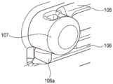
图1A是从正面看时构成根据本发明实施例的杠杆式连接器的凸壳体的透视图。图1B是图1A所示的凸轮凸台周边的放大透视图。1A is a perspective view of a male housing constituting a lever-type connector according to an embodiment of the present invention when viewed from the front. FIG. 1B is an enlarged perspective view of the periphery of the cam boss shown in FIG. 1A .
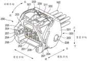
图2A是从正面看时构成根据本发明实施例的杠杆式连接器的凹壳体的透视图。图2B是图2A所示的杠杆侧锁定部件的周边的放大透视图。2A is a perspective view of a female housing constituting a lever-type connector according to an embodiment of the present invention when viewed from the front. FIG. 2B is an enlarged perspective view of the periphery of the lever-side locking member shown in FIG. 2A .
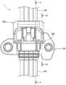
图3是凸壳体和凹壳体之间的装配开始状态的俯视图。FIG. 3 is a plan view of a state where the assembly between the male case and the female case is started.
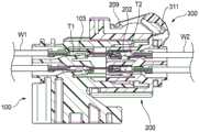
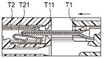
图4A是沿着图3所示的箭头A-A截取的横截面图。图4B是沿着图3所示的箭头B-B截取的横截面图。FIG. 4A is a cross-sectional view taken along arrow A-A shown in FIG. 3 . FIG. 4B is a cross-sectional view taken along arrow B-B shown in FIG. 3 .
图5A和5B分别示出了在凸壳体和凹壳体之间的装配开始状态之前的阶段中凸轮凸台与杠杆之间以及凸端子与凹端子之间的位置关系。图5C和5D分别示出了在凸壳体和凹壳体之间的装配开始状态下凸轮凸台与杠杆之间以及凸端子与凹端子之间的位置关系。图5E和5F分别示出了在凸壳体和凹壳体之间的装配开始状态之后的阶段中凸轮凸台与杠杆之间以及凸端子与凹端子之间的位置关系。5A and 5B respectively show the positional relationship between the cam boss and the lever and between the male terminal and the female terminal in the stage before the fitting start state between the male housing and the female housing. 5C and 5D respectively show the positional relationship between the cam boss and the lever and between the male terminal and the female terminal in the start state of assembling between the male housing and the female housing. 5E and 5F respectively show the positional relationship between the cam boss and the lever and between the male terminal and the female terminal in the stage after the fitting start state between the male housing and the female housing.
图6A是沿着图5A中所示的箭头C-C截取的横截面图。图6B是沿着图5C所示的箭头D-D截取的横截面图。图6C是沿着图5E所示的箭头E-E截取的横截面图。Figure 6A is a cross-sectional view taken along arrows C-C shown in Figure 5A. Figure 6B is a cross-sectional view taken along arrows D-D shown in Figure 5C. Figure 6C is a cross-sectional view taken along arrows E-E shown in Figure 5E.
图7A是从凸壳体侧观察时图6B所示状态的透视图。图7B是图7A所示的杠杆侧锁定部件的周边的放大透视图。Fig. 7A is a perspective view of the state shown in Fig. 6B as viewed from the convex housing side. FIG. 7B is an enlarged perspective view of the periphery of the lever-side locking member shown in FIG. 7A .
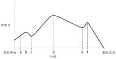
图8是表示在凸壳体和凹壳体之间从装配开始到装配完成的装配力的推移的示例的曲线图。8 is a graph showing an example of the transition of the fitting force between the male case and the female case from the start of the fitting to the completion of the fitting.
具体实施方式Detailed ways
<实施例><Example>
以下给出根据本发明实施例的杠杆式连接器1的描述。A description is given below of the lever type connector 1 according to the embodiment of the present invention.
根据本发明实施例的杠杆式连接器1包括图1A和1B中所示的凸壳体100、图2A和2B中所示的凹壳体200,其装配到凸壳体100以便在其中收容凸壳体100(凸壳体100插入到凹壳体200中),以及可旋转地安装在凹壳体200上的在图2A和2B中所示的杠杆300。The lever-type connector 1 according to the embodiment of the present invention includes the
如图1A和2B以及图2A和2B所示,这里定义了杠杆300的“装配方向”、“宽度方向”、“竖直方向”、“前”、“后”、“上”、“下”和“旋转方向”。“装配方向”、“宽度方向”和“竖直方向”彼此正交。此外,“凸壳体100与凹壳体200的装配时间”也简称为“装配时间”。图2A和2B示出了杆300处于临时锁定位置(装配开始位置)的状态,其中杆300从临时锁定位置(装配开始位置)向前旋转,从而其朝向最终锁定位置(装配完成位置)移动。As shown in FIGS. 1A and 2B and FIGS. 2A and 2B , "assembly direction", "width direction", "vertical direction", "front", "rear", "upper", "lower" of the
如图1A所示,凸壳体100由树脂制成,其包括在宽度方向上较长的方形管状主体周壁部101和与其一体形成的从主体周壁部101的下端沿宽度方向延伸的支撑部102。在主体周壁部101的内部形成有多个收容室103(参照图4A),其分别沿着装配方向延伸,用于在其中收容分别连接到多个(在本实施例中为8个)电线W1的端部的多个凸端子T1(参照图4A)。As shown in FIG. 1A , the
在主体周壁部101的上表面的宽度方向的两端附近,形成有一对上表面肋104。成对的上表面肋104向上方突出,并且沿装配方向在主体周壁部101的整个区域上基本彼此平行地在装配方向上延伸。在主体周壁部101的两个侧表面的上下部形成有上肋105和下肋106,它们分别沿宽度方向向外突出,并且从主体周壁部101的后端附近到沿装配方向从中央稍微向前的位置彼此平行地沿装配方向延伸。A pair of
主体周壁部101在其两个侧表面上分别包括凸轮凸台107。每个凸轮凸台107形成在上肋105和下肋106的前端之间,并且比上肋105和下肋106更大地在宽度方向上向外突出。如图1B所示,凸轮凸台107的横截面的形状(与凸轮凸台107的突出方向正交的横截面的形状)为长径沿装配方向(参照图4A、图4B等)延伸的椭圆形状。The main body
如图2A所示,凹壳体200由树脂制成并且包括在宽度方向上较长的方形管状主体周壁部201。在装配时,将凸壳体100和凹壳体200彼此装配,使得主体周壁部201的内周面和凸壳体100的主体周壁部101的外周面相互重叠(同样参照图3、图4A和4B)。在主体周壁部201的内部沿装配方向分别形成有多个端子收容室202(参照图4A),用于在其中收容分别连接到多个(在该实施例中为8个)电线W2的端部的多个凹端子T2(参照图4A)。As shown in FIG. 2A , the
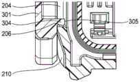
主体周壁部201在其上壁的内表面的宽度方向两端附近具有一对上表面凹槽203。成对的上表面凹槽203向上方凹陷,并且从主体周壁部101的前端向其后侧沿装配方向相互平行地延伸。主体周壁部201在其两侧壁上包括分别沿装配方向延伸的窗口(贯通孔)204。窗口204的上边缘表面205和下边缘表面206从主体周壁部101的前端沿装配方向相互平行地向后延伸。主体周壁部201在其两个侧壁的内表面的前端包括侧表面凹槽207,它们分别与窗口204的上边缘表面205和下边缘表面206的前端连续并且在宽度方向上向外凹陷。The main body
在装配时,凸壳体100的成对的上表面肋104分别插入/引导到成对的上表面凹槽203中,凸壳体100的成对的凸轮凸台107穿过成对的侧表面凹槽207,并且凸壳体100的成对的上肋105和下肋106分别接触/引导到成对的窗口204的上边缘表面205和下边缘表面206。When assembled, the paired
在主体周壁部201的两个侧表面的后侧上的预定位置处,形成有分别在宽度方向上向外突出的一对旋转轴208。在成对的旋转轴208上装配有一对孔303(杠杆300和凹壳体200连接在一起的连接部分),它们形成在杠杆中。因此,杠杆300安装在凹壳体200上,使得其能够围绕成对的旋转轴208旋转。At predetermined positions on the rear sides of both side surfaces of the main body
主体周壁部201包括形成在其上表面的宽度方向中央部分并向上突出的锁定喙209(同样参照图4A)。提供锁定喙209以便将简单地存在于最终锁定位置的杠杆300保持在最终锁定位置(稍后讨论其细节)。The main body
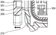
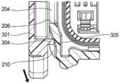
主体周壁部201在其两个侧表面的前侧区域中包括引导倾斜表面210,其分别从窗口204的下边缘表面206向下并且在宽度方向上向内倾斜(参见图4B至6C)。稍后描述引导倾斜表面210的功能等。The main body
如图2A所示,杠杆300由树脂制成并具有大致U形的形状,包括一对侧板部301以及用于将成对的侧板部301的一侧端部连接在一起的连接部302。成对的侧板部301分别具有由贯通孔构成的一对孔303。当凹壳体200的成对的旋转轴208分别插入成对的孔303中时,在成对的侧板部301夹置凹壳体200的两个侧表面的情况下,能够使杠杆300相对于凹壳体200(围绕成对的旋转轴208)旋转。As shown in FIG. 2A , the
在成对的侧板部301的另一端(自由端)附近,分别形成有与其一体的杠杆侧锁定部304,其在宽度方向上向内突出。如图2A和2B所示,在杠杆300处于其临时锁定位置的状态下,成对的杠杆侧锁定部304分别前进到成对的窗口204中,并且被锁定成使得它们被上边缘表面205和下边缘表面206夹置。由于杠杆侧锁定部304的这种锁定,杠杆300被锁定在其临时锁定位置并且被禁止移动到其最终锁定位置。In the vicinity of the other ends (free ends) of the paired
每个杠杆侧锁定部304包括在宽度方向上向内突出的突出部分305。在装配中,成对的突出部分305被位于凸壳体100的成对凸轮凸台107附近的下肋106的前端106a(参见图1B)按压,以升高到下肋106的顶部上,从而使成对的杠杆侧锁定部304在宽度方向上向外弹性变形(参见图6B中所示的箭头)。结果,杠杆侧锁定部304由下边缘表面206的锁定被移除,由此使得杠杆300能够沿着旋转方向从临时锁定位置向着最终锁定位置向前移动。Each lever-
在成对的侧板部301的表面内部沿宽度方向分别形成有凸轮凹槽306(例如参照图4B)。成对的凸轮凹槽306形成为使得在装配时,随着杠杆300从临时锁定位置旋转到最终锁定位置,它们将凸壳体100的成对的凸轮凸台107从凸轮凹槽306的入口部307拉至其最内部308(稍后描述其细节)。这里,每个凸轮凹槽306由在旋转方向上向前存在的侧壁309和与侧壁309连续并沿旋转方向向后存在的侧壁310限定。
在杠杆300的连接部302的旋转方向前端的宽度方向中央部分中形成有锁定喙保持部分311(参见图2A和4A)。锁定喙保持部分311与凹壳体200的锁定喙209(参见图2A和4A)配合,以将简单存在于最终锁定位置的杠杆300保持在最终锁定位置。A locking
具体而言,当杠杆300从临时锁定位置到达最终锁定位置时,锁定喙保持部分311与锁定喙209接触以将其保持。结果,存在于最终锁定位置的杠杆300被保持在最终锁定位置。另一方面,在这种状态下,当锁定喙保持部分311对锁定喙29的保持被移除时,杠杆300能够从最终锁定位置向临时锁定位置移动(沿旋转方向向后)。Specifically, when the
参照图3至图7,下面给出将凸壳体100装配到凹壳体200中的操作的描述。Referring to FIGS. 3 to 7 , a description is given below of the operation of fitting the
首先,在杠杆300被锁定在临时锁定位置的情况下,凹壳体200和凸壳体100的前表面被布置为彼此面对,并且如图5A和5B所示,凸壳体100插入到凹壳体200中。图5A和5B示出了开始装配之前的阶段。First, with the
在图5A和5B所示的阶段,杠杆300的成对的杠杆侧锁定部304的突出部分305还没有被凸壳体100的成对的下肋106的前端106a(参见图1B)按压。因此,如图6A所示,成对的杠杆侧锁定部304(其下表面)被锁定到成对的窗口204的下边缘表面206,从而禁止杠杆300移动到最终锁定位置。此外,在该阶段,如图5B所示,凸端子T1的前端T11还没有被按压成与凹端子T2的弹性变形部T21接触。At the stage shown in FIGS. 5A and 5B , the protruding
接下来,如图5C和5D所示,凸壳体100相对于凹壳体200沿装配方向进一步被按压,从而插入到装配开始状态(同样参见图3以及图4A和4B)。在装配开始状态下,如图5C所示,凸壳体100的成对的凸轮凸台107位于杠杆300的成对的凸轮凹槽306的入口部307中,并开始与凸轮凹槽306的侧壁310接触。Next, as shown in FIGS. 5C and 5D , the
在装配开始状态下,如图7A和7B所示,由于成对的杠杆侧锁定部304的突出部分305被成对的下肋106的前端106a按压以移动到成对的下肋106的顶部上,如图6B所示,成对的杠杆侧锁定部304在宽度方向上向外弹性变形(参见图6B中所示的箭头)。因此,杠杆侧锁定部304由下边缘表面206的锁定被移除,从而使杠杆300能够从临时锁定位置移动到最终锁定位置。这里,如图7B所示,由于成对的杠杆侧锁定部304的突出部分305在成对的下侧肋106的顶部上以与其点接触的方式滑动,所以其摩擦力小于其以面接触方式滑动的情况,从而能够抑制如由滑动运动引起的凸壳体100相对于凹壳体200的按压力的这种增大。In the assembly start state, as shown in FIGS. 7A and 7B , since the protruding
此外,在装配开始状态下,如图5D所示,凸端子T1的前端T11还未被按压成与凹端子T2的弹性变形部T21接触。换句话说,在凸端子T1的前端T11被按压成与凹端子T2的弹性变形部T21接触之前,凸轮凸台107与凸轮凹槽306的侧壁310接触。这是因为,当凸轮凸台107的横截面形状是长径在装配方向上延伸的椭圆形状时,凸轮凸台107与凸轮凹槽306的侧壁310的接触时刻更早于凸轮凸台107的横截面形状为圆形形状的情况。In addition, in the assembly start state, as shown in FIG. 5D , the front end T11 of the male terminal T1 has not yet been pressed into contact with the elastically deformed portion T21 of the female terminal T2. In other words, the
在装配开始状态下,如上所述,杠杆300处于能够从临时锁定位置移动到最终锁定位置的状态。因此,在装配开始状态下,当凸壳体100相对于凹壳体200在装配方向上被进一步按压时,凸轮凸台107按压凸轮凹槽306的侧壁310,由此杠杆300开始从临时锁定位置向最终锁定位置旋转。In the assembly start state, as described above, the
这里,在下面配置的情况下,也就是其中在装配开始状态,杠杆侧锁定部304的突出部分305与下肋106的上表面的向下且沿宽度方向向内倾斜的这样的部分接触,当杠杆侧锁定部304的弹性变形的突出部分305按压下肋106的顶表面(的倾斜部分)时,突出部分305接收到向下的反作用力。在接收到该反作用力时,杠杆300开始从临时锁定位置向最终锁定位置旋转。在这种情况下,为了开始杠杆300从临时锁定位置向最终锁定位置旋转,不需要在装配方向上相对于凹壳体200来按压凸壳体100。Here, in the case of the following configuration, that is, in the assembly start state, the protruding
当杠杆300以这种方式开始从临时锁定位置向最终锁定位置旋转时,如图5E、图5F和图6C所示,成对的杠杆侧锁定部304的弹性变形的突出部分305移动到凹壳体200的成对的引导倾斜表面210上(同样参见图4B至图6C),并且在恢复弹性的同时按压引导倾斜表面210。When the
这里,如上所述,引导倾斜表面210在宽度方向上向下和向内倾斜的同时延伸。因此,当成对的杠杆侧锁定部304的弹性变形的突出部305在恢复弹性的同时按压引导倾斜表面210时,突出部分305接收到向下的反作用力。当接收到该反作用力时,杠杆300接收到沿旋转方向前进的力(朝向最终锁定位置)。换句话说,刚好在由杠杆侧锁定部304的下边缘表面206的锁定移除之后,通过引导倾斜表面210对杠杆300赋予旋转辅助效果。该旋转辅助效果刚好在杠杆300开始从临时锁定位置向最终锁定位置旋转之后使操作感提高。Here, as described above, the guide inclined
在杠杆300开始从临时锁定位置向最终锁定位置旋转之后,杠杆300在接收到旋转辅助效果的同时朝向最终锁定位置旋转。因此,由于凸轮凹槽306的侧壁309根据杠杆300的旋转的进程将凸轮凸台107朝向凹壳体200的后侧按压,所以凸轮凸台107(并且最终是凸壳体100)被拉向凹壳体200的后侧(参照图5E)。After the
随着杠杆300的旋转的进行,成对的杠杆侧锁定部304的突出部分305在引导倾斜表面210上滑动。在这种情况下,如图6C所示,突出部分305在引导倾斜表面210上以与其点接触方式滑动。因此,摩擦阻力小于它们以面接触滑动时的情况,由此能够抑制如由突出部分的滑动引起的凸壳体100相对于凹壳体200的按压力的这种增大。As the rotation of the
随着杠杆300在旋转方向上的前向旋转的进行,上述旋转辅助效果随着杠杆侧锁定部304的弹性变形量减少而逐渐减小。在该实施例中,如图5E和6C所示,在杠杆300在旋转方向上的前向旋转进行并且杠杆侧锁定部304完全恢复弹性的时间附近(即在旋转辅助效果消失的时间附近),如图5F所示,凸端子T1的前端T11被按压成与凹端子T2的弹性变形部T21接触。As the forward rotation of the
即使在凸端子T1的前端T11被按压成与凹端子T2的弹性变形部T21接触之后,当杠杆300进一步向最终锁定位置旋转时,凸轮凹槽306的侧壁309将凸轮凸台107进一步压向凹壳体200的后侧,由此,随着杠杆300的转动的进行,凸轮凸台107(以及最终是凸壳体100)被进一步拉向凹壳体200的后侧。Even after the front end T11 of the male terminal T1 is pressed into contact with the elastic deformation portion T21 of the female terminal T2, when the
并且当杠杆300到达最终锁定位置时,凸轮凸台107到达凸轮凹槽306的最深部(参见图4A、4B以及图5A至5F),凸壳体100成为装配完成状态,如上所述,杠杆300的锁定喙保持部311(参照图4A)与凹壳体200的锁定喙209(参照图4A)接触以将其保持。这完成了分别设置在凸壳体100和凹壳体200(参照图4A)中的凸端子T1和凹端子T2之间的导通连接,并且杠杆300保持在最终锁定位置。And when the
参考图8,下面给出了在装配时凸壳体100在装配方向上从凸壳体100和凹壳体200的前表面的位置彼此重合的状态的移动量(在下文中称为“行程”)与凸壳体100在装配方向上其相对于凹壳体200的运动所需的压力(装配力)之间的关系的示例的附加描述。Referring to FIG. 8 , the amount of movement (hereinafter referred to as “stroke”) of the
在图8中,行程a对应于通过凸壳体100的下肋106的前端106a(参见图1B)按压杠杆侧锁定部304的突出部分305开始时(即杠杆侧锁定部304的弹性变形开始时)的时刻。行程b对应于上述装配开始状态(杠杆侧锁定部304的弹性变形量增大以移除通过杠杆侧锁定部304的下边缘表面206的锁定的状态,且凸轮凸台107开始与凸轮凹槽306接触)。行程c对应于杠杆侧锁定部304完全恢复弹性且凸端子T1的前端T11被按压成与凹端子T2的弹性变形部T21接触的时刻。行程d对应于由凸端子T1的前端的压入引起的凹端子T2的弹性变形部T2的弹性变形量最大化的时刻。行程e对应于锁定喙保持部311开始对锁定喙209的保持操作的时刻。行程f对应于锁定喙保持部311对锁定喙209的保持操作完成时的时刻(即上述的装配完成状态)。In FIG. 8 , the stroke a corresponds to when the protruding
如图8所示,即使在行程a之前,由于在壳体的滑动运动期间产生的摩擦力(在主体周部101、201的滑动期间产生的摩擦力)等,按压力变化为逐渐增大。从行程a到行程b,随着杠杆侧锁定部304的弹性变形量的增加,将由凸壳体100接收的沿宽度方向向内的反作用力增大,从而按压力增加。从行程b到行程c,由于上述的旋转辅助效果,按压力减小。从行程c到行程d,压入阻力随着如由凸端子T1的前端T11的压入引起的凹端子T2的弹性变形部T21的弹性变形量的这种增加而增加,由此按压力增加。从行程d到行程e,按压力由于例如由凸轮凹槽306的形状等引起的凸轮凸台107和凸轮凹槽306之间的滑动阻力的减小而减小。并且从行程e到行程f,按压力由于由锁定喙保持部311的保持操作以保持锁喙209引起的阻力的增加而增加。As shown in FIG. 8 , even before the stroke a, the pressing force changes to gradually increase due to the frictional force generated during the sliding motion of the housing (frictional force generated during the sliding of the main body
如上所述,根据本发明实施例的杠杆式连接器1,在装配时,凸壳体100的凸轮凸台107在凸端子T1被压入凹端子T2之前与杠杆300的凸轮凹槽306接触。换句话说,由于凸端子1的按压接触的开始而使装配所需的力的大小增大时的时刻可以与由于通过凸轮凸台107开始杠杆300的旋转而使装配所需的力的大小增大时的时刻不同。因此,当与凸端子T1的按压接触和通过凸轮凸台107的杠杆300的旋转开始在相同时刻被执行的实施例相比时,可以减小同时装配所需的力的增加的大小。As described above, according to the lever type connector 1 of the embodiment of the present invention, during assembly, the
因此,本实施例的杠杆式连接器1能够抑制装配所需的力的大的变动,因此能够提高装配作业性。Therefore, the lever-type connector 1 of the present embodiment can suppress large fluctuations in the force required for assembly, so that assembly workability can be improved.
另外,凸轮凸台107的横截面形状提供长径沿着装配方向延伸(参见图1B)的椭圆形状。因此,当与凸轮凸台107的横截面形状提供圆形形状的情况相比,能够使凸轮凸台107与杠杆300的凸轮凹槽306接触的时刻提前。结果,在不改变凸轮凸台107的位置的情况下,可以使凸端子T1的按压接触的时刻和通过凸轮凸台107的杠杆300的旋转开始的时刻彼此不同。Additionally, the cross-sectional shape of the
<其他实施例><Other Examples>
这里,本发明不限于上述实施例,在本发明的范围内可以适当地采用各种修改、改进等。此外,上述实施例的各个组成元件的材料、形状、尺寸、数量、布置位置等是任意的,但不限于此,只要它们能够实现本发明即可。Here, the present invention is not limited to the above-described embodiments, and various modifications, improvements, and the like can be appropriately adopted within the scope of the present invention. In addition, the materials, shapes, dimensions, numbers, arrangement positions, etc. of the respective constituent elements of the above-described embodiments are arbitrary, but not limited thereto, as long as they can realize the present invention.
例如,在上述实施例中,杠杆300的杠杆侧锁定部304的突出部分305在凹壳体200的引导倾斜表面210上以点接触滑动(参见图6C)。然而,突出部分305的形状也可被设计成使得突出部分305在凹壳体200的引导倾斜表面210上以线接触滑动。与面接触滑动运动相比,这样设计的形状也可以降低摩擦阻力,由此能够抑制如由滑动运动引起的凸壳体100相对于凹壳体200的按压力的这种增大。For example, in the above-described embodiment, the protruding
这里,根据本发明的杠杆式连接器1的实施例的特征简要地列举为以下配置(1)和(2)。Here, the features of the embodiment of the lever type connector 1 according to the present invention are briefly listed as the following configurations (1) and (2).
(1)一种杠杆式连接器(1),包括:(1) A lever-type connector (1), comprising:
第一壳体(100)和第二壳体(200),所述第一壳体和第二壳体能够彼此装配;和a first case (100) and a second case (200), the first case and the second case being capable of being assembled with each other; and
安装在所述第二壳体上的杠杆(300),a lever (300) mounted on the second housing,
其中,所述第一壳体(100)包括能够在其中收容第一端子(T1)的第一端子收容室(103),以及凸轮凸台(107),当所述第一壳体(100)和第二壳体(200)彼此装配时,所述凸轮凸台沿着装配方向与所述第一壳体一起移动,Wherein, the first housing (100) includes a first terminal accommodating chamber (103) capable of accommodating a first terminal (T1) therein, and a cam boss (107), when the first housing (100) When the second casing (200) is assembled with each other, the cam boss moves together with the first casing along the assembly direction,
其中,所述第二壳体(200)包括能够在其中收容第二端子(T2)的第二端子收容室(202),Wherein, the second housing (200) includes a second terminal accommodating chamber (202) capable of accommodating the second terminal (T2) therein,
其中,所述杠杆(300)包括能够接收所述凸轮凸台的凸轮凹槽(306),wherein the lever (300) includes a cam groove (306) capable of receiving the cam boss,
其中,所述杠杆使所述第一壳体和第二壳体彼此接近,并且在使所述凸轮凸台沿着所述凸轮凹槽移动的同时使所述第一端子和第二端子彼此按压接触,并且wherein the lever brings the first and second housings close to each other and presses the first and second terminals against each other while moving the cam boss along the cam groove contact, and
其中,在所述第一端子(T1)和第二端子(T2)彼此按压接触之前,所述凸轮凸台(107)和凸轮凹槽(306)形成彼此接触。Wherein, before the first terminal (T1) and the second terminal (T2) are in pressing contact with each other, the cam boss (107) and the cam groove (306) are brought into contact with each other.
(2)根据上述构造(1)所述的杠杆式连接器,(2) The lever type connector according to the above configuration (1),
其中,所述凸轮凸台(107)具有长径沿着所述装配方向延伸的椭圆形横截面形状。Wherein, the cam boss (107) has an oval cross-sectional shape with a long diameter extending along the assembly direction.
附图标记列表List of reference signs
1:杠杆式连接器1: Lever Connector
100:凸壳体(第一壳体)100: Convex shell (first shell)
103:端子收容室(第一端子收容室)103: Terminal storage room (first terminal storage room)
107:凸轮凸台107: Cam boss
200:凹壳体(第二壳体)200: Concave shell (second shell)
202:端子收容室(第二端子收容室)202: Terminal storage room (second terminal storage room)
300:杠杆300: Leverage
306:凸轮凹槽306: Cam groove
T1:凸端子(第一端子)T1: male terminal (first terminal)
T2:凹端子(第二端子)T2: female terminal (second terminal)
Claims (2)
Applications Claiming Priority (2)
| Application Number | Priority Date | Filing Date | Title |
|---|---|---|---|
| JP2017036757AJP6574798B2 (en) | 2017-02-28 | 2017-02-28 | Lever type connector |
| JP2017-036757 | 2017-02-28 |
Publications (2)
| Publication Number | Publication Date |
|---|---|
| CN108511975A CN108511975A (en) | 2018-09-07 |
| CN108511975Btrue CN108511975B (en) | 2020-09-29 |
Family
ID=63112383
Family Applications (1)
| Application Number | Title | Priority Date | Filing Date |
|---|---|---|---|
| CN201810159002.3AActiveCN108511975B (en) | 2017-02-28 | 2018-02-26 | Lever type connector |
Country Status (4)
| Country | Link |
|---|---|
| US (1) | US10490939B2 (en) |
| JP (1) | JP6574798B2 (en) |
| CN (1) | CN108511975B (en) |
| DE (1) | DE102018202277B4 (en) |
Families Citing this family (3)
| Publication number | Priority date | Publication date | Assignee | Title |
|---|---|---|---|---|
| JP6574799B2 (en)* | 2017-02-28 | 2019-09-11 | 矢崎総業株式会社 | Lever type connector |
| JP6618509B2 (en)* | 2017-06-06 | 2019-12-11 | 矢崎総業株式会社 | Lever type connector |
| JP7010886B2 (en)* | 2019-06-06 | 2022-01-26 | 矢崎総業株式会社 | Connector and power circuit breaker |
Citations (4)
| Publication number | Priority date | Publication date | Assignee | Title |
|---|---|---|---|---|
| JP2002134223A (en)* | 2000-10-23 | 2002-05-10 | Sumitomo Wiring Syst Ltd | Connector |
| CN104584335A (en)* | 2012-08-06 | 2015-04-29 | 矢崎总业株式会社 | Charging inlet device |
| JP2015133204A (en)* | 2014-01-10 | 2015-07-23 | イリソ電子工業株式会社 | Connector |
| US9106000B2 (en)* | 2012-09-06 | 2015-08-11 | Sumitomo Wiring Systems, Ltd. | Connector and connector assembly |
Family Cites Families (20)
| Publication number | Priority date | Publication date | Assignee | Title |
|---|---|---|---|---|
| US5458496A (en)* | 1993-07-12 | 1995-10-17 | Sumitomo Wiring Systems, Ltd. | Charge coupling for electric vehicle |
| EP0727846B1 (en)* | 1993-11-05 | 2001-01-24 | SUMITOMO WIRING SYSTEMS, Ltd. | Lever type connector |
| US5709560A (en)* | 1994-12-14 | 1998-01-20 | Sumitomo Wiring Systems, Ltd. | Connector having a pivotable connection-assistance member |
| JP3715115B2 (en)* | 1998-09-10 | 2005-11-09 | 矢崎総業株式会社 | Lever fitting type connector |
| JP2001035591A (en)* | 1999-07-16 | 2001-02-09 | Sumitomo Wiring Syst Ltd | Lever-type connector |
| DE19938930C1 (en)* | 1999-08-17 | 2001-04-12 | Framatome Connectors Int | Electrical connector |
| US6558176B1 (en)* | 2002-03-07 | 2003-05-06 | Tyco Electronics Corp. | Mate assist assembly for connecting electrical contacts |
| JP2004303440A (en)* | 2003-03-28 | 2004-10-28 | Sumitomo Wiring Syst Ltd | Lever type connector |
| JP2006147492A (en)* | 2004-11-24 | 2006-06-08 | Sumitomo Wiring Syst Ltd | Connector |
| JP4678333B2 (en)* | 2005-09-29 | 2011-04-27 | 住友電装株式会社 | Lever type connector |
| JP4622930B2 (en)* | 2006-04-20 | 2011-02-02 | 住友電装株式会社 | Lever type connector |
| JP4884158B2 (en) | 2006-06-26 | 2012-02-29 | 矢崎総業株式会社 | Lever type connector |
| JP2009093930A (en)* | 2007-10-10 | 2009-04-30 | Sumitomo Wiring Syst Ltd | Lever type connector |
| JP2009117059A (en) | 2007-11-02 | 2009-05-28 | Yazaki Corp | connector |
| JP5354815B2 (en)* | 2009-07-06 | 2013-11-27 | 矢崎総業株式会社 | Wire or cable |
| JP2011023127A (en)* | 2009-07-13 | 2011-02-03 | Sumitomo Wiring Syst Ltd | Lever type connector |
| JP5582091B2 (en)* | 2011-05-11 | 2014-09-03 | 住友電装株式会社 | Lever type connector |
| JP5783468B2 (en)* | 2012-10-29 | 2015-09-24 | 住友電装株式会社 | connector |
| JP2016207414A (en)* | 2015-04-21 | 2016-12-08 | 住友電装株式会社 | connector |
| JP6441866B2 (en)* | 2016-09-21 | 2018-12-19 | 矢崎総業株式会社 | Lever type connector |
- 2017
- 2017-02-28JPJP2017036757Apatent/JP6574798B2/enactiveActive
- 2018
- 2018-01-11USUS15/868,093patent/US10490939B2/enactiveActive
- 2018-02-14DEDE102018202277.1Apatent/DE102018202277B4/enactiveActive
- 2018-02-26CNCN201810159002.3Apatent/CN108511975B/enactiveActive
Patent Citations (4)
| Publication number | Priority date | Publication date | Assignee | Title |
|---|---|---|---|---|
| JP2002134223A (en)* | 2000-10-23 | 2002-05-10 | Sumitomo Wiring Syst Ltd | Connector |
| CN104584335A (en)* | 2012-08-06 | 2015-04-29 | 矢崎总业株式会社 | Charging inlet device |
| US9106000B2 (en)* | 2012-09-06 | 2015-08-11 | Sumitomo Wiring Systems, Ltd. | Connector and connector assembly |
| JP2015133204A (en)* | 2014-01-10 | 2015-07-23 | イリソ電子工業株式会社 | Connector |
Also Published As
| Publication number | Publication date |
|---|---|
| JP6574798B2 (en) | 2019-09-11 |
| JP2018142479A (en) | 2018-09-13 |
| CN108511975A (en) | 2018-09-07 |
| US20180248311A1 (en) | 2018-08-30 |
| DE102018202277B4 (en) | 2021-10-07 |
| DE102018202277A1 (en) | 2018-08-30 |
| US10490939B2 (en) | 2019-11-26 |
Similar Documents
| Publication | Publication Date | Title |
|---|---|---|
| JP5193888B2 (en) | connector | |
| CN100511860C (en) | Lever type connector | |
| JP4857048B2 (en) | Lever type connector | |
| CN108511975B (en) | Lever type connector | |
| JPH09204956A (en) | Lever type connector | |
| JP5784529B2 (en) | Lever type connector | |
| JP2003249305A (en) | Lever type connector | |
| JP4579082B2 (en) | Rotating lever type connector | |
| CN108511976B (en) | Lever type connector | |
| JP2004319225A (en) | Lever type connector | |
| JP2002270286A (en) | Lever-driven connector assembly | |
| JP5035359B2 (en) | Lever type connector | |
| CN109066213B (en) | rod connector | |
| JP6018016B2 (en) | connector | |
| EP2771946A1 (en) | Connector | |
| JP2002260780A (en) | Connector assembly | |
| JP4705675B2 (en) | Double acting mechanical support connector | |
| JP3035776B1 (en) | connector | |
| CN115411571A (en) | Connector comprising a rod and connector system provided with a connector comprising a rod | |
| JP2009059510A (en) | Waterproof connector | |
| JP2000082542A (en) | Half mating prevention connector | |
| JP6131110B2 (en) | Female terminals and connectors | |
| JP2018206647A (en) | Lever type connector | |
| CN110120604B (en) | Connector component and connector | |
| JP2002289303A (en) | Connector assembly body of lever driving type |
Legal Events
| Date | Code | Title | Description |
|---|---|---|---|
| PB01 | Publication | ||
| PB01 | Publication | ||
| SE01 | Entry into force of request for substantive examination | ||
| SE01 | Entry into force of request for substantive examination | ||
| GR01 | Patent grant | ||
| GR01 | Patent grant |