CN108507502B - Method for measuring engineering collimation parameters of accelerator - Google Patents
Method for measuring engineering collimation parameters of acceleratorDownload PDFInfo
- Publication number
- CN108507502B CN108507502BCN201711258153.6ACN201711258153ACN108507502BCN 108507502 BCN108507502 BCN 108507502BCN 201711258153 ACN201711258153 ACN 201711258153ACN 108507502 BCN108507502 BCN 108507502B
- Authority
- CN
- China
- Prior art keywords
- value
- calculating
- parameters
- collimation
- parameter
- Prior art date
- Legal status (The legal status is an assumption and is not a legal conclusion. Google has not performed a legal analysis and makes no representation as to the accuracy of the status listed.)
- Active
Links
- 238000000034methodMethods0.000titleclaimsabstractdescription46
- 238000004364calculation methodMethods0.000claimsabstractdescription16
- 230000009466transformationEffects0.000claimsabstractdescription9
- 238000013016dampingMethods0.000claimsabstractdescription7
- 238000009434installationMethods0.000claimsabstractdescription5
- 238000005259measurementMethods0.000claimsabstractdescription5
- 238000000354decomposition reactionMethods0.000claimsabstractdescription4
- 239000011159matrix materialSubstances0.000claimsdescription29
- 238000012937correctionMethods0.000claimsdescription15
- 238000006243chemical reactionMethods0.000claimsdescription10
- 238000012897Levenberg–Marquardt algorithmMethods0.000claimsdescription8
- YBJHBAHKTGYVGT-ZKWXMUAHSA-N(+)-BiotinChemical compoundN1C(=O)N[C@@H]2[C@H](CCCCC(=O)O)SC[C@@H]21YBJHBAHKTGYVGT-ZKWXMUAHSA-N0.000claimsdescription3
- 238000013461designMethods0.000claimsdescription3
- FEPMHVLSLDOMQC-UHFFFAOYSA-Nvirginiamycin-S1Natural productsCC1OC(=O)C(C=2C=CC=CC=2)NC(=O)C2CC(=O)CCN2C(=O)C(CC=2C=CC=CC=2)N(C)C(=O)C2CCCN2C(=O)C(CC)NC(=O)C1NC(=O)C1=NC=CC=C1OFEPMHVLSLDOMQC-UHFFFAOYSA-N0.000claimsdescription3
- 238000010276constructionMethods0.000claims2
- 230000017105transpositionEffects0.000claims1
- 238000012360testing methodMethods0.000description5
- 238000012546transferMethods0.000description2
- 230000009286beneficial effectEffects0.000description1
- 230000007812deficiencyEffects0.000description1
- 238000010586diagramMethods0.000description1
- 238000004519manufacturing processMethods0.000description1
- 238000000691measurement methodMethods0.000description1
- 238000012986modificationMethods0.000description1
- 230000004048modificationEffects0.000description1
- 238000005457optimizationMethods0.000description1
- 238000013519translationMethods0.000description1
Images


Classifications
- G—PHYSICS
- G01—MEASURING; TESTING
- G01B—MEASURING LENGTH, THICKNESS OR SIMILAR LINEAR DIMENSIONS; MEASURING ANGLES; MEASURING AREAS; MEASURING IRREGULARITIES OF SURFACES OR CONTOURS
- G01B11/00—Measuring arrangements characterised by the use of optical techniques
- G01B11/26—Measuring arrangements characterised by the use of optical techniques for measuring angles or tapers; for testing the alignment of axes
- G01B11/27—Measuring arrangements characterised by the use of optical techniques for measuring angles or tapers; for testing the alignment of axes for testing the alignment of axes
- G01B11/272—Measuring arrangements characterised by the use of optical techniques for measuring angles or tapers; for testing the alignment of axes for testing the alignment of axes using photoelectric detection means
Landscapes
- Physics & Mathematics (AREA)
- General Physics & Mathematics (AREA)
- Length Measuring Devices By Optical Means (AREA)
Abstract
Description
Translated fromChinese技术领域technical field
本发明涉及精密工程与工业测量技术领域,尤其是涉及一种加速器工程准直参数的测量方法。The invention relates to the technical field of precision engineering and industrial measurement, in particular to a method for measuring alignment parameters of accelerator engineering.
背景技术Background technique
目前,在诸如航空航天、汽车制造、加速器、射电望远镜等大尺寸工程数字化安装中,大多采用高精度全站仪、激光跟踪仪、摄影测量等仪器,其准直参数(3个平移量、3个旋转量)的正确性和可靠性显得尤为重要。然而准直参数的测量方法中,清华大学的发明专利目标测量点只能取3个点,显然没有充分的多余观测量,测量精度不高。浙江大学的发明专利以最小二乘误差作为目标函数,利用牛顿法求解最优化问题,但是牛顿法太过依赖初值,且宜不收敛。商用软件Spatial Analyzer采用阻尼最小二乘法,实现了大角度情况下准直参数的求解,然而在坐标系原点偏离元件中心会产生偏差,且其抗差解法不具备自动化赋权,求解效率和精度都不高。At present, in the digital installation of large-scale projects such as aerospace, automobile manufacturing, accelerators, and radio telescopes, most of the high-precision total stations, laser trackers, photogrammetry and other instruments are used. The correctness and reliability of the rotation amount) are particularly important. However, in the measurement method of the collimation parameter, the target measurement points of the invention patent of Tsinghua University can only take 3 points, obviously there is not enough redundant observation, and the measurement accuracy is not high. The invention patent of Zhejiang University uses the least square error as the objective function, and uses the Newton method to solve the optimization problem, but the Newton method relies too much on the initial value and should not converge. The commercial software Spatial Analyzer uses the damped least squares method to solve the collimation parameters in the case of large angles. However, when the origin of the coordinate system deviates from the center of the component, deviations will occur, and the robust solution method does not have automatic weighting, and the solution efficiency and accuracy are both high. not tall.
发明内容SUMMARY OF THE INVENTION
本发明的目的在于针对现有技术的不足提供一种加速器工程准直参数的测量方法。从而有效解决现有技术中的问题。The purpose of the present invention is to provide a method for measuring the collimation parameters of accelerator engineering in view of the deficiencies of the prior art. Thus, the problems in the prior art can be effectively solved.
为实现上述目的,本发明采取的技术方案为:所述的一种加速器工程准直参数的测量方法,其特点通过建立机械设备标定理论值与实测安装值的坐标转化关系,依据奇异值分解法求得设备的姿态参数,具体包括如下步骤:In order to achieve the above-mentioned purpose, the technical scheme adopted in the present invention is as follows: the method for measuring the collimation parameters of an accelerator engineering is characterized by establishing the coordinate transformation relationship between the theoretical value of mechanical equipment calibration and the measured installation value, and according to the singular value decomposition method. Obtaining the attitude parameters of the device includes the following steps:
(1)首先根据设计尺寸,建立全局坐标系,确定环形加速器原点为其圆心,直线加速器原点为其长轴中心,水平面向上法向为Y轴正向,长轴为Z轴,右手定则确定第三轴指向;(1) First, establish a global coordinate system according to the design size, determine the origin of the circular accelerator as the center of the circle, the origin of the linear accelerator as the center of the long axis, the normal direction of the horizontal plane upward is the positive direction of the Y axis, the long axis is the Z axis, and the right-hand rule is determined. The third axis points to;
(2)使用控制器、数据线连接高精度全站仪、激光跟踪仪、便携式测量臂或摄影测量仪器和电脑,对待安装元件进行标定,建立其中心局部坐标系,将其基准转移至3个以上的外部靶标座,使用激光跟踪这些外部靶标座,得到基准理论值;(2) Use the controller and data cable to connect the high-precision total station, laser tracker, portable measuring arm or photogrammetry instrument and computer, calibrate the components to be installed, establish their central local coordinate system, and transfer their datums to three For the above external target coordinates, use the laser to track these external target coordinates to obtain the benchmark theoretical value;
(3)使用高精度全站仪、激光跟踪仪、便携式测量臂或摄影测量,恢复全局坐标系,并现场安装该元件,再次测量步骤二的外部靶标座,得到实测值;(3) Use a high-precision total station, a laser tracker, a portable measuring arm or photogrammetry to restore the global coordinate system, install the component on site, and measure the external target coordinates of
(4)利用两组3个以上靶座的坐标值,求得准直参数;大角度情况下采用阻尼最小二乘法求解,小角度或坐标系偏心情况下采用结构总体最小二乘法求解,存在粗差情况下采用拟稳平差求解;(4) Use the coordinate values of two or more target bases to obtain the collimation parameters; in the case of large angles, the damped least squares method is used to solve them, and in the case of small angles or the eccentricity of the coordinate system, the overall least squares method of the structure is used to solve them. Use quasi-stable adjustment to solve in poor condition;
(5)完成准直参数求解,显示并保存结果。(5) Complete the solution of collimation parameters, display and save the results.
所述的步骤四中的阻尼最小二乘法包括如下步骤:The damped least squares method in the fourth step includes the following steps:
a)指定转换参数初值xk=(0,0,0,0,0,0,0,1),阻尼因子初值uk=0.001,其中下标k为迭代次数,取值为0,1...n;a) Specify the initial value of the conversion parameter xk = (0, 0, 0, 0, 0, 0, 0, 1), the initial value of the damping factor uk = 0.001, where the subscript k is the number of iterations, and the value is 0, 1...n;
b)组建误差方程V=BX+L,其中B为系数矩阵,L为常数矩阵,V为误差矩阵;b) set up the error equation V=BX+L, wherein B is the coefficient matrix, L is the constant matrix, and V is the error matrix;
c)构建线性方程组
d)计算参数改正数dxk,参数估值xk+1=xk+dxkd) Calculate parameter correction number dxk , parameter estimate xk+1 =xk +dxk
e)如果参数改正数dxk≤10-8,计算结束,输出xk+1;e) If the parameter correction number dxk ≤ 10-8 , the calculation ends, and output xk+1 ;
f)如果参数改正数不满足步骤e)条件,则按
g)按
h)按
i)按
j)如果比例因子C<0.25,则:
k)如果比例因子0.25≤C≤0.75,则:
l)如果比例因子C>0.75,再进行如下分步骤l) If the scale factor C>0.75, then proceed to the following sub-steps
1)令μk=μk/2;1) Let μk = μk/2 ;
2)如果μk<S,则
3)如果μk≥S,则继续进行步骤1),直至μk<S,执行步骤2);3) If μk ≥ S, proceed to step 1) until μk <S, and execute step 2);
m)根据步骤j)、k)、l)三步骤计算的迭代值,再执行步骤d),直至e)步骤出现。所述的步骤四中的结构总体最小二乘法求解包括如下步骤:m) According to the iteration value calculated in the three steps of steps j), k) and l), perform step d) until step e) occurs. The structural overall least squares solution in the described
a)指定转换参数初值x0=(0,0,0,0,0,0,0,1),系数阵改正向量初值EA0=0; b)按以下步骤构造结构矩阵D;a) Specify the initial value of the conversion parameter x0 =(0, 0, 0, 0, 0, 0, 0, 1), and the initial value of the coefficient matrix correction vector EA0 =0; b) Construct the structure matrix D according to the following steps;
1)构造四个矩阵:

2)构造结构矩阵五个分量:

3)则
c)按以下步骤计算转换矩阵R:c) Calculate the transformation matrix R as follows:
1)构造矩阵

2)计算转换矩阵R=[-Im FD];2) Calculate the transformation matrix R=[-Im FD];
d)按下式计算参数改正数dx,参数估值xk=x0+dx;d) Calculate the parameter correction number dx according to the following formula, parameter estimation xk =x0 +dx ;
e)
f)如果norm(dx)≤10-8,则
g)否则,根据e)式计算拉格朗日常数向量M;g) Otherwise, calculate the Lagrangian number vector M according to the formula e);
h)计算迭代值;h) Calculate the iteration value;
i)
k)
l)再次执行d),直至满足f)条件,计算结束。l) Execute d) again until the condition f) is satisfied, and the calculation ends.
所述的步骤四中的拟稳平差求解包括如下步骤:The quasi-stable adjustment solution in the fourth step includes the following steps:
a)计算三维坐标分量差;a) Calculate the three-dimensional coordinate component difference;
b)
c)计算三维坐标分量差均值;c) Calculate the mean value of the three-dimensional coordinate component difference;
d)
e)计算三维坐标分量残差;e) Calculate the residuals of the three-dimensional coordinate components;
f)
g)计算残差中位数;g) Calculate the median of residuals;
h)
i)计算三维坐标单位权中误差;i) Calculate the error in the weight of the three-dimensional coordinate unit;
j)
k)按以下步骤定权P;k) Determine the weight P according to the following steps;
1)如果abs(Vi/σ)≤1.5则P=1;1) If abs(Vi /σ)≤1.5, then P=1;
2)否则P=0;2) Otherwise P=0;
l)计算转换参数;l) Calculate the conversion parameters;
m)x=(BTPB)-1BTPL。m)x = (BT PB)-1 BT PL.
本发明的有益效果是:所述的一种加速器工程准直参数的测量方法,其采用阻尼最小二乘、结构总体最小二乘和拟稳估计三种方法,解决大角度、坐标系偏心和存在粗差情况下准直参数的求解问题;能够配合激光跟踪仪、便携式测量臂或全站仪使用,完成准直参数的计算;具备在任何角度下,都可计算准直参数;具备在坐标系偏心下,不必移动坐标系,即可准确计算准直参数;具备在存在粗差下,也可不损失精度地计算准直参数。提高了计算效率和精度,具备抗差性。The beneficial effects of the present invention are as follows: the method for measuring the engineering collimation parameters of the accelerator adopts three methods: damping least squares, overall least squares of the structure and quasi-stable estimation, so as to solve the problems of large angle, eccentricity of the coordinate system and existence of Solving the problem of collimation parameters in the case of gross error; can be used with laser tracker, portable measuring arm or total station to complete the calculation of collimation parameters; it can calculate the collimation parameters at any angle; it can be used in the coordinate system Under eccentricity, the collimation parameters can be calculated accurately without moving the coordinate system; if there is a gross error, the collimation parameters can also be calculated without loss of accuracy. The calculation efficiency and accuracy are improved, and it is resistant to differences.
附图说明:Description of drawings:
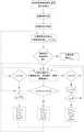
图1是本发明的总体流程示意图;Fig. 1 is the overall flow schematic diagram of the present invention;
图2是本发明的阻尼最下二乘流程图;Fig. 2 is the damping lowest square flow chart of the present invention;
图3是本发明的结构总体最小二乘流程图;Fig. 3 is the structure overall least squares flow chart of the present invention;
图4是本发明的拟稳估计流程。FIG. 4 is the quasi-stable estimation flow of the present invention.
具体实施方式Detailed ways
以下结合附图所示之最佳实例作进一步详述:Below in conjunction with the best example shown in the accompanying drawings to be described in further detail:
如图1至4所示,所述的一种加速器工程准直参数的测量方法,其特点通过建立机械设备标定理论值与实测安装值的坐标转化关系,依据奇异值分解法求得设备的姿态参数,具体包括如下步骤:As shown in Figures 1 to 4, the described method for measuring the collimation parameters of accelerator engineering is characterized by establishing the coordinate transformation relationship between the theoretical value of mechanical equipment calibration and the measured installation value, and obtaining the attitude of the equipment according to the singular value decomposition method. parameters, including the following steps:
(1)首先根据设计尺寸,建立全局坐标系,确定环形加速器原点为其圆心,直线加速器原点为其长轴中心,水平面向上法向为Y轴正向,长轴为Z轴,右手定则确定第三轴指向;(1) First, establish a global coordinate system according to the design size, determine the origin of the circular accelerator as the center of the circle, the origin of the linear accelerator as the center of the long axis, the normal direction of the horizontal plane upward is the positive direction of the Y axis, the long axis is the Z axis, and the right-hand rule is determined. The third axis points to;
(2)使用控制器、数据线连接高精度全站仪、激光跟踪仪、便携式测量臂或摄影测量仪器和电脑,对待安装元件进行标定,建立其中心局部坐标系,将其基准转移至3个以上的外部靶标座,使用激光跟踪这些外部靶标座,得到基准理论值;(2) Use the controller and data cable to connect the high-precision total station, laser tracker, portable measuring arm or photogrammetry instrument and computer, calibrate the components to be installed, establish their central local coordinate system, and transfer their datums to three For the above external target coordinates, use the laser to track these external target coordinates to obtain the benchmark theoretical value;
(3)使用高精度全站仪、激光跟踪仪、便携式测量臂或摄影测量,恢复全局坐标系,并现场安装该元件,再次测量步骤二的外部靶标座,得到实测值;(3) Use a high-precision total station, a laser tracker, a portable measuring arm or photogrammetry to restore the global coordinate system, install the component on site, and measure the external target coordinates of
(4)利用两组3个以上靶座的坐标值,求得准直参数;大角度情况下采用阻尼最小二乘法求解,小角度或坐标系偏心情况下采用结构总体最小二乘法求解,存在粗差情况下采用拟稳平差求解;(4) Use the coordinate values of two or more target bases to obtain the collimation parameters; in the case of large angles, the damped least squares method is used to solve them, and in the case of small angles or the eccentricity of the coordinate system, the overall least squares method of the structure is used to solve them. Use quasi-stable adjustment to solve in poor condition;
(5)完成准直参数求解,显示并保存结果。(5) Complete the solution of collimation parameters, display and save the results.
所述的步骤四中的阻尼最小二乘法包括如下步骤:The damped least squares method in the fourth step includes the following steps:
a)指定转换参数初值xk=(0,0,0,0,0,0,0,1),阻尼因子初值uk=0.001,其中下标k为迭代次数,取值为0,1...n;a) Specify the initial value of the conversion parameter xk = (0, 0, 0, 0, 0, 0, 0, 1), the initial value of the damping factor uk = 0.001, where the subscript k is the number of iterations, and the value is 0, 1...n;
b)组建误差方程V=BX+L,其中B为系数矩阵,L为常数矩阵,V为误差矩阵;b) set up the error equation V=BX+L, wherein B is the coefficient matrix, L is the constant matrix, and V is the error matrix;
c)构建线性方程组
d)计算参数改正数dxk,参数估值xk+1=xk+dxkd) Calculate parameter correction number dxk , parameter estimate xk+1 =xk +dxk
e)如果参数改正数dxk≤10-8,计算结束,输出xk+1;e) If the parameter correction number dxk ≤ 10-8 , the calculation ends, and output xk+1 ;
f)如果参数改正数不满足步骤e)条件,则按
g)按
h)按
i)按
j)如果比例因子C<0.25,则:
k)如果比例因子0.25≤C≤0.75,则:
l)如果比例因子C>0.75,再进行如下分步骤l) If the scale factor C>0.75, then proceed to the following sub-steps
1)令μk=μk/2;1) Let μk = μk/2 ;
2)如果μk<S,则
3)如果μk≥S,则继续进行步骤1),直至μk<S,执行步骤6);3) If μk ≥ S, proceed to step 1) until μk <S, and execute step 6);
m)根据步骤j)、k)、l)三步骤计算的迭代值,再执行步骤d),直至e)步骤出现。所述的步骤四中的结构总体最小二乘法求解包括如下步骤:m) According to the iteration value calculated in the three steps of steps j), k) and l), perform step d) until step e) occurs. The structural overall least squares solution in the described
a)指定转换参数初值x0=(0,0,0,0,0,0,0,1),系数阵改正向量初值EA0=0;a) Specify the initial value of the conversion parameter x0 =(0, 0, 0, 0, 0, 0, 0, 1), and the initial value of the coefficient matrix correction vector EA0 =0;
b)按以下步骤构造结构矩阵D;b) construct the structure matrix D according to the following steps;
1)构造四个矩阵:

2)构造结构矩阵五个分量:

3)则
c)按以下步骤计算转换矩阵R:c) Calculate the transformation matrix R as follows:
1)构造矩阵

2)计算转换矩阵R=[-Im FD];2) Calculate the transformation matrix R=[-Im FD];
d)按下式计算参数改正数dx,参数估值xk=x0+dx; e)
f)如果norm(dx)≤10-8,则
g)否则,根据e)式计算拉格朗日常数向量M;g) Otherwise, calculate the Lagrangian number vector M according to the formula e);
h)计算迭代值;h) Calculate the iteration value;
i)
j)更换迭代值;j) replace the iteration value;
k)
l)再次执行d),直至满足f)条件,计算结束。l) Execute d) again until the condition f) is satisfied, and the calculation ends.
所述的步骤四中的拟稳平差求解包括如下步骤:The quasi-stable adjustment solution in the fourth step includes the following steps:
a)计算三维坐标分量差;a) Calculate the three-dimensional coordinate component difference;
b)
d)
e)计算三维坐标分量残差;e) Calculate the residuals of the three-dimensional coordinate components;
f)
g)计算残差中位数;g) Calculate the median of residuals;
h)
i)计算三维坐标单位权中误差;i) Calculate the error in the weight of the three-dimensional coordinate unit;
j)
k)按以下步骤定权P;k) Determine the weight P according to the following steps;
1)如果abs(Vi/σ)≤1.5则P=1;1) If abs(Vi /σ)≤1.5, then P=1;
2)否则P=0;2) Otherwise P=0;
l)计算转换参数;l) Calculate the conversion parameters;
m)x=(BTPB)-1BTPL。m)x=(BT PB)-1 BT PL.
实施例1:阻尼最小二乘法计算大角度Example 1: Damped Least Squares Calculating Large Angles
案例1具有理论值,属于大角度,故采用阻尼最小二乘法计算后与理论值比对,具体结果见表1和2。
表1方法1测试数据表Table 1

表2方法1准直参数计算值误差及其与理论值比对表Table 2
实施例2:结构总体最小二乘法计算坐标系偏心Example 2: Calculation of Coordinate System Eccentricity by Structural Overall Least Squares
案例2坐标系偏心,故按结构总体最小二乘法计算,具体见过见表3、4、5。The coordinate system of
表3方法2测试数据表Table 3

表4方法2测试数据平移量统计表Table 4
表5方法1准直参数计算值误差表Table 5

实施例3:含有粗差情况下拟稳估计法Example 3: Quasi-stable estimation method with gross errors
粗差案例,按拟稳估计计算,具体结果见表6、7和8。The gross error case is calculated according to the quasi-stable estimation, and the specific results are shown in Tables 6, 7 and 8.
表6方法3测试数据表(无粗差)Table 6 Method 3 test data table (no gross error)

表7方法3测试数据表(粗差)Table 7 Method 3 Test Data Table (Gross Error)

表8方法3有无粗差计算参数结果比对表Table 8 Method 3 with or without gross error calculation parameter results comparison table

以上所述仅为本发明的较佳实施例,并不用以限制本发明,凡在本发明的精神和原则之内,所作的任何修改、等同替换、改进等,均应包含在本发明的保护范围之内。The above are only preferred embodiments of the present invention and are not intended to limit the present invention. Any modifications, equivalent replacements, improvements, etc. made within the spirit and principles of the present invention shall be included in the protection of the present invention. within the range.
Claims (4)


Priority Applications (1)
| Application Number | Priority Date | Filing Date | Title |
|---|---|---|---|
| CN201711258153.6ACN108507502B (en) | 2017-12-04 | 2017-12-04 | Method for measuring engineering collimation parameters of accelerator |
Applications Claiming Priority (1)
| Application Number | Priority Date | Filing Date | Title |
|---|---|---|---|
| CN201711258153.6ACN108507502B (en) | 2017-12-04 | 2017-12-04 | Method for measuring engineering collimation parameters of accelerator |
Publications (2)
| Publication Number | Publication Date |
|---|---|
| CN108507502A CN108507502A (en) | 2018-09-07 |
| CN108507502Btrue CN108507502B (en) | 2020-06-16 |
Family
ID=63375425
Family Applications (1)
| Application Number | Title | Priority Date | Filing Date |
|---|---|---|---|
| CN201711258153.6AActiveCN108507502B (en) | 2017-12-04 | 2017-12-04 | Method for measuring engineering collimation parameters of accelerator |
Country Status (1)
| Country | Link |
|---|---|
| CN (1) | CN108507502B (en) |
Families Citing this family (2)
| Publication number | Priority date | Publication date | Assignee | Title |
|---|---|---|---|---|
| CN111238375B (en)* | 2020-03-16 | 2022-06-03 | 北京卫星制造厂有限公司 | Shape reconstruction method for large components of mobile inspection robot based on laser tracker |
| CN117984074B (en)* | 2024-03-29 | 2024-07-12 | 成都飞机工业(集团)有限责任公司 | Gesture-adjusting positioning method for large three-dimensional assembly without fixed measuring points |
Citations (5)
| Publication number | Priority date | Publication date | Assignee | Title |
|---|---|---|---|---|
| JPS61277012A (en)* | 1985-06-03 | 1986-12-08 | Nippon Telegr & Teleph Corp <Ntt> | Method and apparatus for correcting position and posture of camera |
| CN101363715A (en)* | 2008-09-26 | 2009-02-11 | 浙江大学 | Aircraft fuselage attitude calculation method based on laser tracker |
| CN102519441A (en)* | 2011-12-06 | 2012-06-27 | 南京航空航天大学 | Method for measuring positioning points based on laser tracker in docking process of airplane parts |
| CN104101326A (en)* | 2013-04-08 | 2014-10-15 | 同济大学 | Automatic measurement method and apparatus for shield attitude based on spatial geometry analysis |
| CN105404238A (en)* | 2015-10-22 | 2016-03-16 | 南京航空航天大学 | Probe position linearization calibration method for on-machine laser measurement |
- 2017
- 2017-12-04CNCN201711258153.6Apatent/CN108507502B/enactiveActive
Patent Citations (5)
| Publication number | Priority date | Publication date | Assignee | Title |
|---|---|---|---|---|
| JPS61277012A (en)* | 1985-06-03 | 1986-12-08 | Nippon Telegr & Teleph Corp <Ntt> | Method and apparatus for correcting position and posture of camera |
| CN101363715A (en)* | 2008-09-26 | 2009-02-11 | 浙江大学 | Aircraft fuselage attitude calculation method based on laser tracker |
| CN102519441A (en)* | 2011-12-06 | 2012-06-27 | 南京航空航天大学 | Method for measuring positioning points based on laser tracker in docking process of airplane parts |
| CN104101326A (en)* | 2013-04-08 | 2014-10-15 | 同济大学 | Automatic measurement method and apparatus for shield attitude based on spatial geometry analysis |
| CN105404238A (en)* | 2015-10-22 | 2016-03-16 | 南京航空航天大学 | Probe position linearization calibration method for on-machine laser measurement |
Non-Patent Citations (2)
| Title |
|---|
| 三维直角坐标转换的一种阻尼最小二乘稳健估计法;罗长林 等;《武汉大学学报·信息科学版》;20070831;第32卷(第8期);707-710* |
| 浅谈测量平差中的总体最小二乘法;蒲正川 等;《科技致富向导》;20111231(第35期);261* |
Also Published As
| Publication number | Publication date |
|---|---|
| CN108507502A (en) | 2018-09-07 |
Similar Documents
| Publication | Publication Date | Title |
|---|---|---|
| CN114518586B (en) | GNSS precise single-point positioning method based on spherical harmonic expansion | |
| US9658055B2 (en) | Accuracy traceability method based on precision coordinate control network for workshop measurement positioning system | |
| CN109974749B (en) | Evaluation method for comprehensive pointing error of three-axis turntable | |
| CN108413988B (en) | Method for quickly calibrating coordinate system of theodolite at tail end of robot | |
| CN108759798B (en) | Method for realizing precision measurement of high-precision spacecraft | |
| CN104406610B (en) | A kind of magnetometer real time correction device and method | |
| CN110146839A (en) | A Calibration Method for Magnetic Gradient Tensor System of Mobile Platform | |
| CN107167119B (en) | Data processing method for projection deformation | |
| CN105823417B (en) | A kind of method for turning station precision based on photogrammetric raising laser tracker | |
| CN104344804B (en) | Satellite simulation zero gravity state single machine pointing accuracy measurement method | |
| CN104315983A (en) | Method for increasing coordinate measurement field accuracy through space multi-length constraint | |
| CN106443722A (en) | Method for detecting antenna phase center bias | |
| CN110516350B (en) | ERS point error correction method based on anisotropic weighting | |
| CN108317993A (en) | A kind of deviation of plumb line measuring device and method of integrated GNSS and laser tracker | |
| CN109129465B (en) | A robot hand-eye calibration system and its workflow | |
| CN109669196B (en) | A Precise Attitude Measurement Method for Multi-antenna GNSS Carrier Phase Considering Baseline Deformation | |
| CN104197839B (en) | Compensation method for spacecraft assembly accuracy influenced by gravity and temperature | |
| CN108507502B (en) | Method for measuring engineering collimation parameters of accelerator | |
| CN106885585A (en) | A kind of satellite borne photography measuring system integration calibration method based on bundle adjustment | |
| CN114722455A (en) | Three-dimensional engineering control network construction method combining total station and laser tracker | |
| CN111046584B (en) | Precise adjustment method for satellite-borne instrument and equipment | |
| CN108037318A (en) | A kind of unmanned plane accelerometer calibration method based on ellipsoid fitting | |
| CN110132283A (en) | A method and system for locating ground stationary targets by an unmanned aerial vehicle optoelectronic platform | |
| CN110672094B (en) | Distributed POS multi-node multi-parameter instant synchronous calibration method | |
| CN113702994A (en) | Laser tracker measurement accuracy improving method based on rigid constraint |
Legal Events
| Date | Code | Title | Description |
|---|---|---|---|
| PB01 | Publication | ||
| PB01 | Publication | ||
| SE01 | Entry into force of request for substantive examination | ||
| SE01 | Entry into force of request for substantive examination | ||
| GR01 | Patent grant | ||
| GR01 | Patent grant |