CN108490483B - Signal transmission device and system - Google Patents
Signal transmission device and systemDownload PDFInfo
- Publication number
- CN108490483B CN108490483BCN201810343578.5ACN201810343578ACN108490483BCN 108490483 BCN108490483 BCN 108490483BCN 201810343578 ACN201810343578 ACN 201810343578ACN 108490483 BCN108490483 BCN 108490483B
- Authority
- CN
- China
- Prior art keywords
- signal
- current loop
- pin
- circuit
- loop generator
- Prior art date
- Legal status (The legal status is an assumption and is not a legal conclusion. Google has not performed a legal analysis and makes no representation as to the accuracy of the status listed.)
- Active
Links
- 230000008054signal transmissionEffects0.000titleclaimsabstractdescription75
- 239000003990capacitorSubstances0.000claimsdescription36
- 238000006243chemical reactionMethods0.000claimsdescription17
- 230000005540biological transmissionEffects0.000abstractdescription20
- 238000010586diagramMethods0.000description12
- 238000000034methodMethods0.000description8
- 230000008569processEffects0.000description5
- 238000002955isolationMethods0.000description4
- 230000009286beneficial effectEffects0.000description2
- 230000002452interceptive effectEffects0.000description2
- 230000004048modificationEffects0.000description2
- 238000012986modificationMethods0.000description2
- 238000012544monitoring processMethods0.000description2
- HBBGRARXTFLTSG-UHFFFAOYSA-NLithium ionChemical compound[Li+]HBBGRARXTFLTSG-UHFFFAOYSA-N0.000description1
- 239000003245coalSubstances0.000description1
- 230000007812deficiencyEffects0.000description1
- 238000013461designMethods0.000description1
- 230000007613environmental effectEffects0.000description1
- 238000001914filtrationMethods0.000description1
- 230000006872improvementEffects0.000description1
- 230000003993interactionEffects0.000description1
- 229910001416lithium ionInorganic materials0.000description1
- 238000004519manufacturing processMethods0.000description1
- 238000004806packaging method and processMethods0.000description1
- 230000009467reductionEffects0.000description1
- 238000012360testing methodMethods0.000description1
Images


Classifications
- G—PHYSICS
- G01—MEASURING; TESTING
- G01V—GEOPHYSICS; GRAVITATIONAL MEASUREMENTS; DETECTING MASSES OR OBJECTS; TAGS
- G01V1/00—Seismology; Seismic or acoustic prospecting or detecting
- G01V1/22—Transmitting seismic signals to recording or processing apparatus
Landscapes
- Engineering & Computer Science (AREA)
- Remote Sensing (AREA)
- Physics & Mathematics (AREA)
- Life Sciences & Earth Sciences (AREA)
- Acoustics & Sound (AREA)
- Environmental & Geological Engineering (AREA)
- Geology (AREA)
- General Life Sciences & Earth Sciences (AREA)
- General Physics & Mathematics (AREA)
- Geophysics (AREA)
- Amplifiers (AREA)
- Arrangements For Transmission Of Measured Signals (AREA)
Abstract
Translated fromChinese
Description
Translated fromChinese技术领域technical field
本发明涉及基于地震勘探的数据传输技术领域,具体而言,涉及一种信号传输装置及系统。The present invention relates to the technical field of data transmission based on seismic exploration, in particular, to a signal transmission device and system.
背景技术Background technique
在地震勘探中,比如在露天矿井、地下矿山等恶劣环境下,通常需要在特定位置埋设地震检波器,用于对矿山微震事件进行定位和分析,从而实现振动监测、预报、预警的工作,这对于保证矿山安全和高效生产至关重要。检波器在探测到微震事件时,将会产生低至几微伏,高至数十伏的电压信号,并将该信号传输到矿山井下的数据采集装置。In seismic exploration, for example, in harsh environments such as open pit mines and underground mines, it is usually necessary to bury seismometers at specific locations to locate and analyze mine microseismic events, so as to realize vibration monitoring, forecasting, and early warning work. It is essential to ensure mine safety and efficient production. When the geophone detects a microseismic event, it will generate a voltage signal as low as a few microvolts and as high as tens of volts, and transmit the signal to the data acquisition device in the mine.
由于井下环境条件比较恶劣,通常采用防爆型数据采集装置,这些装置通常比较笨重,安装和维护不便,降低了微震监测系统的可靠性,不利于矿山安全。微震检波器探测到的电压信号一般比较微弱,从井下到地面所需要的信号传输电缆较长(其长度可能超过10km),阻抗大,对微弱的电压信号造成衰减,有的矿井(比如煤矿井)电磁干扰比较严重,进一步导致测试信号严重偏离原始信号。即,在现有技术中,地震勘探中,微震信号比较微弱、动态范围大,且容易受到电磁干扰,难以实现远距离传输。因此,如何提供一种可解决上述问题的方案,已成为本领域技术人员的一大难题。Due to the harsh underground environmental conditions, explosion-proof data acquisition devices are usually used. These devices are usually cumbersome and inconvenient to install and maintain, which reduces the reliability of the microseismic monitoring system and is not conducive to mine safety. The voltage signal detected by the microseismic detector is generally weak. The signal transmission cable required from the underground to the ground is long (the length may exceed 10km), and the impedance is large, which will attenuate the weak voltage signal. Some mines (such as coal mines) ) The electromagnetic interference is more serious, which further causes the test signal to deviate from the original signal seriously. That is, in the prior art, in seismic exploration, the microseismic signal is relatively weak, has a large dynamic range, and is susceptible to electromagnetic interference, making it difficult to achieve long-distance transmission. Therefore, how to provide a solution that can solve the above problems has become a major problem for those skilled in the art.
发明内容SUMMARY OF THE INVENTION
为了克服上述现有技术中的不足,本发明提供一种电路结构简单易于实现的信号传输装置及系统,以解决上述问题。In order to overcome the above-mentioned deficiencies in the prior art, the present invention provides a signal transmission device and system with a simple and easy-to-implement circuit structure to solve the above-mentioned problems.
为了实现上述目的,本发明较佳实施例所提供的技术方案如下所示:In order to achieve the above purpose, the technical solution provided by the preferred embodiment of the present invention is as follows:
本发明较佳实施例提供一种信号传输装置,所述信号传输装置包括:A preferred embodiment of the present invention provides a signal transmission device, and the signal transmission device includes:
信号发送模块,用于与信号源连接,所述信号发送模块包括信号发送电路,所述信号发送电路包括电平转换器及电流环发生器;所述电平转换器用于与所述信号源连接,并将所述信号源产生的待传输信号转换为第一电压信号;所述电流环发生器与所述电平转换器连接,用于将所述第一电压信号转换为电流环信号并输出;a signal sending module for connecting with a signal source, the signal sending module includes a signal sending circuit, the signal sending circuit includes a level converter and a current loop generator; the level converter is used for connecting with the signal source , and convert the signal to be transmitted generated by the signal source into a first voltage signal; the current loop generator is connected to the level shifter for converting the first voltage signal into a current loop signal and outputting ;
信号接收模块,与所述电流环发生器连接,用于从所述电流环发生器接收经过所述信号发送模块放大的所述电流环信号,并将所述电流环信号进行隔离放大并转换为电压信号输出。a signal receiving module, connected with the current loop generator, for receiving the current loop signal amplified by the signal sending module from the current loop generator, isolating and amplifying the current loop signal and converting it into Voltage signal output.
可选地,上述信号发送电路还包括第一信号放大器,所述第一信号放大器与所述电流环发生器及所述信号接收模块连接,用于从所述电流环发生器接收所述电流环信号,并对所述电流环信号进行放大,并输出至所述信号接收模块。Optionally, the above-mentioned signal transmission circuit further includes a first signal amplifier, and the first signal amplifier is connected to the current loop generator and the signal receiving module, and is used for receiving the current loop from the current loop generator. signal, amplify the current loop signal, and output to the signal receiving module.
可选地,上述电平转换器的第一管脚、第八管脚均与第一电容的一端连接,所述第一电容的另一端接地;Optionally, the first pin and the eighth pin of the above-mentioned level shifter are both connected to one end of the first capacitor, and the other end of the first capacitor is grounded;
所述电平转换器的第二管脚、第三管脚均与所述信号源连接;The second pin and the third pin of the level shifter are both connected to the signal source;
所述电平转换器的第四管脚接地;the fourth pin of the level shifter is grounded;
所述电平转换器的第五管脚、第六管脚均与第一电阻的一端连接,所述第一电阻的另一端与所述电流环发生器的第二管脚连接;The fifth pin and the sixth pin of the level shifter are both connected to one end of the first resistor, and the other end of the first resistor is connected to the second pin of the current loop generator;
所述电平转换器的第七管脚与第二电容的一端连接,所述第二电容的另一端接地;The seventh pin of the level shifter is connected to one end of the second capacitor, and the other end of the second capacitor is grounded;
所述电流环发生器的第一管脚与第三电容的一端连接,所述第三电容的另一端接地,所述电流环发生器的第一管脚还与第二电阻的一端连接,所述第二电阻的另一端经由第四电阻接地;The first pin of the current loop generator is connected to one end of the third capacitor, the other end of the third capacitor is grounded, and the first pin of the current loop generator is also connected to one end of the second resistor, so the other end of the second resistor is grounded via the fourth resistor;
所述电流环发生器的第三管脚接地;the third pin of the current loop generator is grounded;
所述电流环发生器的第四管脚、第七管脚与所述信号接收模块连接,用于输出放大后的所述电流环信号;The fourth pin and the seventh pin of the current loop generator are connected to the signal receiving module for outputting the amplified current loop signal;
所述电流环发生器的第五管脚与所述第一信号放大器的发射极连接;the fifth pin of the current loop generator is connected to the emitter of the first signal amplifier;
所述电流环发生器的第六管脚与所述第一信号放大器的基极连接;The sixth pin of the current loop generator is connected to the base of the first signal amplifier;
所述电流环发生器的第七管脚还与所述第一信号放大器的集电极连接;The seventh pin of the current loop generator is also connected to the collector of the first signal amplifier;
所述电流环发生器的第八管脚通过第五电容接地;The eighth pin of the current loop generator is grounded through the fifth capacitor;
所述电流环发生器的第四管脚与第七管脚跨接第六电容及二极管,所述二极管的正极管脚与所述电流环发生器的第四管脚连接,所述二极管的负极管脚与所述电流环发生器的第七管脚连接。The fourth pin and the seventh pin of the current loop generator are connected across a sixth capacitor and a diode, the positive pin of the diode is connected to the fourth pin of the current loop generator, and the negative electrode of the diode is connected to the fourth pin of the current loop generator. The pin is connected to the seventh pin of the current loop generator.
可选地,上述第一信号放大器为三极管。Optionally, the above-mentioned first signal amplifier is a triode.
可选地,上述信号接收模块包括信号接收电路,所述信号接收电路包括电源转换子电路及信号接收转换子电路;Optionally, the above-mentioned signal receiving module includes a signal receiving circuit, and the signal receiving circuit includes a power conversion sub-circuit and a signal receiving and conversion sub-circuit;
所述电源转换子电路与所述信号接收转换子电路连接,用于将供电电源转换为预设参数的电源以为所述信号接收转换子电路提供电能,所述信号接收转换子电路还与所述电流环发生器连接。The power conversion sub-circuit is connected with the signal receiving and converting sub-circuit, and is used for converting the power supply into a power supply with preset parameters to provide power for the signal receiving and converting sub-circuit, and the signal receiving and converting sub-circuit is further connected with the said signal receiving and converting sub-circuit. Current loop generator connection.
可选地,上述信号接收转换子电路包括第一DC/DC转换器、第二信号放大器,所述第一DC/DC转换器与所述电流环发生器连接;Optionally, the signal receiving and converting sub-circuit includes a first DC/DC converter and a second signal amplifier, and the first DC/DC converter is connected to the current loop generator;
所述第二信号放大器与所述电流环发生器连接,用于将放大后的所述电流环信号转换为所述电压信号并输出。The second signal amplifier is connected to the current loop generator, and is used for converting the amplified current loop signal into the voltage signal and outputting it.
可选地,上述第二信号放大器为隔离式放大器。Optionally, the above-mentioned second signal amplifier is an isolated amplifier.
可选地,上述电源转换子电路包括与所述供电电源连接的第二DC/DC转换器。Optionally, the above-mentioned power conversion sub-circuit includes a second DC/DC converter connected to the power supply.
可选地,上述信号传输装置还包括与所述信号接收模块连接的电源模块。Optionally, the above signal transmission device further includes a power supply module connected to the signal receiving module.
本发明较佳实施例还一种信号传输系统,包括信号源、信号接收装置及上述的信号传输装置,所述信号源与所述信号传输装置中的信号发送模块连接,所述信号接收装置与所述信号传输装置中的信号接收模块连接。A preferred embodiment of the present invention also provides a signal transmission system, comprising a signal source, a signal receiving device and the above-mentioned signal transmission device, wherein the signal source is connected to a signal sending module in the signal transmission device, and the signal receiving device is connected to The signal receiving module in the signal transmission device is connected.
相对于现有技术而言,本发明提供的信号传输装置及系统至少具有以下有益效果:在信号传输装置中,信号发送模块用于与信号源连接,信号发送模块包括信号发送电路,信号发送电路包括电平转换器及电流环发生器。电平转换器用于与信号源连接,并将信号源产生的待传输信号转换为第一电压信号;电流环发生器与电平转换器连接,用于将第一电压信号转换为电流环信号并输出;信号接收模块,与电流环发生器连接,用于从电流环发生器接收经过信号发送模块放大的电流环信号,并将电流环信号进行隔离放大并转换为电压信号输出。本方案提供的信号传输装置及系统结构简单,易于实现,通过将信号源产生的待传输信号转换为电流环信号进行传输,有助于减少信号失真,提高信号传输的可靠性,并延长传输距离。Compared with the prior art, the signal transmission device and system provided by the present invention have at least the following beneficial effects: in the signal transmission device, a signal transmission module is used to connect with a signal source, the signal transmission module includes a signal transmission circuit, and the signal transmission circuit Including level shifter and current loop generator. The level converter is used for connecting with the signal source and converting the signal to be transmitted generated by the signal source into a first voltage signal; the current loop generator is connected with the level converter for converting the first voltage signal into a current loop signal and Output; the signal receiving module is connected with the current loop generator, and is used for receiving the current loop signal amplified by the signal sending module from the current loop generator, and isolating and amplifying the current loop signal and converting it into a voltage signal for output. The signal transmission device and system provided by this solution have a simple structure and are easy to implement. By converting the signal to be transmitted generated by the signal source into a current loop signal for transmission, it is helpful to reduce signal distortion, improve the reliability of signal transmission, and extend the transmission distance. .
为使本发明的上述目的、特征和优点能更明显易懂,下文特举本发明较佳实施例,并配合所附附图,作详细说明如下。In order to make the above-mentioned objects, features and advantages of the present invention more clearly understood, preferred embodiments of the present invention are exemplified below, and are described in detail as follows in conjunction with the accompanying drawings.
附图说明Description of drawings
为了更清楚地说明本发明实施例的技术方案,下面将对实施例中所需要使用的附图作简单地介绍。应当理解,以下附图仅示出了本发明的某些实施例,因此不应被看作是对范围的限定,对于本领域普通技术人员来讲,在不付出创造性劳动的前提下,还可以根据这些附图获得其他相关的附图。In order to illustrate the technical solutions of the embodiments of the present invention more clearly, the accompanying drawings required in the embodiments will be briefly introduced below. It should be understood that the following drawings only show some embodiments of the present invention, and therefore should not be regarded as a limitation of the scope. Other related figures are obtained from these figures.
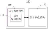
图1为本发明较佳实施例提供的信号传输装置的方框示意图。FIG. 1 is a schematic block diagram of a signal transmission apparatus according to a preferred embodiment of the present invention.
图2为本发明较佳实施例提供的信号传输系统的交互示意图。FIG. 2 is an interactive schematic diagram of a signal transmission system provided by a preferred embodiment of the present invention.
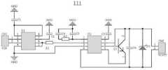
图3为本发明较佳实施例提供的信号发送模块的电路原理示意意图。FIG. 3 is a schematic diagram of a circuit principle of a signal sending module provided by a preferred embodiment of the present invention.
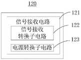
图4为本发明较佳实施例提供的信号接收模块的方框示意图。FIG. 4 is a schematic block diagram of a signal receiving module according to a preferred embodiment of the present invention.
图5为本发明较佳实施例提供的信号接收转换子电路的电路原理示意图。FIG. 5 is a schematic diagram of a circuit principle of a signal receiving and converting sub-circuit provided by a preferred embodiment of the present invention.
图6为本发明较佳实施例提供的电源转换子电路的电路原理示意图。FIG. 6 is a schematic diagram of a circuit principle of a power conversion sub-circuit provided by a preferred embodiment of the present invention.
图标:10-信号传输系统;100-信号传输装置;110-信号发送模块;111-信号发送电路;120-信号接收模块;121-信号接收电路;122-信号接收转换子电路;123-电源转换子电路;200-信号源;300-信号接收装置。Icon: 10-signal transmission system; 100-signal transmission device; 110-signal transmission module; 111-signal transmission circuit; 120-signal reception module; 121-signal reception circuit; 122-signal reception conversion sub-circuit; 123-power conversion Subcircuit; 200-signal source; 300-signal receiving device.
具体实施方式Detailed ways
下面将结合本发明实施例中的附图,对本发明实施例中的技术方案进行清楚、完整地描述。显然,所描述的实施例仅仅是本发明的一部分实施例,而不是全部的实施例。通常在此处附图中描述和示出的本发明实施例的组件可以以各种不同的配置来布置和设计。The technical solutions in the embodiments of the present invention will be clearly and completely described below with reference to the accompanying drawings in the embodiments of the present invention. Obviously, the described embodiments are only some, but not all, embodiments of the present invention. The components of the embodiments of the invention generally described and illustrated in the drawings herein may be arranged and designed in a variety of different configurations.
因此,以下对在附图中提供的本发明的实施例的详细描述并非旨在限制要求保护的本发明的范围,而是仅仅表示本发明的选定实施例。基于本发明的实施例,本领域技术人员在没有做出创造性劳动的前提下所获得的所有其他实施例,都属于本发明保护的范围。Thus, the following detailed description of the embodiments of the invention provided in the accompanying drawings is not intended to limit the scope of the invention as claimed, but is merely representative of selected embodiments of the invention. Based on the embodiments of the present invention, all other embodiments obtained by those skilled in the art without creative work fall within the protection scope of the present invention.
应注意到:相似的标号和字母在下面的附图中表示类似项,因此,一旦某一项在一个附图中被定义,则在随后的附图中不需要对其进行进一步定义和解释。此外,术语“第一”、“第二”等仅用于区分描述,而不能理解为指示或暗示相对重要性。It should be noted that like numerals and letters refer to like items in the following figures, so once an item is defined in one figure, it does not require further definition and explanation in subsequent figures. Furthermore, the terms "first", "second", etc. are only used to differentiate the description and should not be construed to indicate or imply relative importance.
下面结合附图,对本发明的一些实施方式作详细说明。在不冲突的情况下,下述的实施例及实施例中的特征可以相互组合。Some embodiments of the present invention will be described in detail below with reference to the accompanying drawings. The embodiments described below and features in the embodiments may be combined with each other without conflict.
请结合参照图1和图2,其中,图1为本发明较佳实施例提供的信号传输装置100的方框示意图,图2为本发明较佳实施例提供的信号传输系统10的交互示意图。本发明提供的信号传输装置100可以在地质勘探中,对信号源200产生的信号进行传输。可理解地,该信号源200为用于采集地质数据的装置,比如为用于检测地震波的检波器,或者为用于检测地质振动的振动传感器等。在使用时,信号源200通常埋设于地表下。信号源200在检查到相应的地质数据时,便会基于地质数据生成相应的信号,该信号便为待传输信号。Please refer to FIG. 1 and FIG. 2 in combination, wherein FIG. 1 is a schematic block diagram of a
进一步地,信号传输装置100可以在矿场勘探中使用,用于在检测矿场的微振动过程中对信号源200采集的微振动信号进行传输。可理解地,在矿场勘探过程中,通常需要测量矿场的微振动,以便于矿场坍塌前发出报警提示。Further, the
在本实施例中,信号源200通常深埋于地下,以便于减少地面的干扰,使得采集的数据更为准确,而该方式使得信号源200与信号接收装置300的距离较远。也就是信号源200产生的信号在现有技术中无法直接传输至信号接收设备。本发明通过信号传输装置100实现信号源200与信号接收设备之间的数据交互,进而解决信号源200产生的信号不能远距离传输的问题。In this embodiment, the
在本实施例中,信号传输装置100可以包括信号接收模块120及信号发送模块110。其中,信号接收模块120可以包括信号接收电路121。当然,该信号接收模块120还可以包括用于封装信号接收电路121的外壳。In this embodiment, the
进一步地,信号发送电路111可以包括电平转换器及电流环发生器。电平转换器用于与信号源200连接,并将信号源200产生的待传输信号转换为第一电压信号;电流环发生器与电平转换器连接,用于将第一电压信号转换为电流环信号并输出。Further, the
信号接收模块120与电流环发生器连接,用于从电流环发生器接收经过信号发送模块110放大的电流环信号,并将电流环信号进行隔离放大并转换为电压信号输出。The
可选地,信号发送电路111还可以包括第一信号放大器。第一信号放大器与电流环发生器及信号接收模块120连接,用于从电流环发生器接收电流环信号,并对电流环信号进行放大,并输出至信号接收模块120。Optionally, the
请参照图3,为本发明较佳实施例提供的信号发送模块110的电路原理示意意图。在图3中,该第一信号放大器可以为三极管D1,用于对电流环信号进行放大。当然,在其他实施方式中,该第一信号放大器也可以为信号放大芯片,这里对第一信号放大器不作具体限定。Please refer to FIG. 3 , which is a schematic diagram of the circuit principle of the
请再次参照图3,在本实施例中,信号源200产生的信号通常为电压信号,电平转换器(U1)用于将该电压信号转换为低电压信号。信号发送电路111可以包括第一连接端CN1及第二连接端CN2,该电平转换器的第一管脚(管脚1)、第八管脚(管脚8)均与第一电容C1连接,该第一电容C1的另一端接地,用于滤波。其中,第一管脚与第八管脚为电平转换器的参考电压管脚。Referring to FIG. 3 again, in this embodiment, the signal generated by the
电平转换器的第二管脚(管脚2)、第三管脚(管脚3)均与信号源200连接,其中,电平转换器的第二管脚与第一连接端CN1的管脚1连接,电平转换器的第三管脚与第一连接端CN1的管脚2连接,以使得信号源200产生的信号输入至信号传输装置100,第二连接端CN2用于输出电流环信号。The second pin (pin 2) and the third pin (pin 3) of the level shifter are both connected to the
电平转换器的第四管脚(管脚4)接地,即第四管脚为电平转换器的负电源管脚。电平转换器的第五管脚(管脚5)、第六管脚(管脚6)均与第一电阻R1的一端连接,第一电阻R1的另一端与电流环发生器(U2)的第二管脚(管脚2)连接,该第一电阻R1与电流环发生器相配合,用于将电平转换器输出的电压信号转换为电流环信号。电平转换器的第七管脚(管脚7)与第二电容C2的一端连接,第二电容C2的另一端接地。The fourth pin (pin 4) of the level shifter is grounded, that is, the fourth pin is the negative power supply pin of the level shifter. The fifth pin (pin 5) and the sixth pin (pin 6) of the level shifter are both connected to one end of the first resistor R1, and the other end of the first resistor R1 is connected to the current loop generator (U2). The second pin (pin 2) is connected, and the first resistor R1 cooperates with the current loop generator to convert the voltage signal output by the level shifter into a current loop signal. The seventh pin (pin 7) of the level shifter is connected to one end of the second capacitor C2, and the other end of the second capacitor C2 is grounded.
电流环发生器的第一管脚(管脚1)与第三电容C3的一端连接,第三电容C3的另一端接地,电流环发生器的第一管脚还与第二电阻R2的一端连接,第二电阻R2的另一端经由第四电阻R4接地。The first pin (pin 1) of the current loop generator is connected to one end of the third capacitor C3, the other end of the third capacitor C3 is grounded, and the first pin of the current loop generator is also connected to one end of the second resistor R2 , the other end of the second resistor R2 is grounded via the fourth resistor R4.
电流环发生器的第三管脚(管脚3)接地。电流环发生器的第四管脚(管脚4)、第七管脚(管脚7)与信号接收模块120连接,用于输出放大后的电流环信号。电流环发生器的第五管脚(管脚5)与第一信号放大器的发射极连接。电流环发生器的第六管脚(管脚6)与第一信号放大器的基极连接。电流环发生器的第七管脚还与第一信号放大器的集电极连接。电流环发生器的第八管脚(管脚8)通过第五电容C5接地。电流环发生器的第四管脚与第七管脚跨接第六电容C6及二极管D1,二极管D1的正极管脚与电流环发生器的第四管脚连接,二极管的负极管脚与电流环发生器的第七管脚连接。The third pin (pin 3) of the current loop generator is grounded. The fourth pin (pin 4) and the seventh pin (pin 7) of the current loop generator are connected to the
请结合参照图4和图5,其中,图4为本发明较佳实施例提供的信号接收模块120的方框示意图,图5为本发明较佳实施例提供的信号接收转换子电路122的电路原理示意图。在本实施例中,信号接收模块120可以包括信号接收电路121,信号接收电路121可以包括电源转换子电路123及信号接收转换子电路122。信号接收转换子电路122可以包括第三连接端CN3及第四连接端CN4。Please refer to FIG. 4 and FIG. 5 in combination, wherein FIG. 4 is a block diagram of the
电源转换子电路123与信号接收转换子电路122连接,用于将供电电源转换为预设参数的电源以为信号接收转换子电路122提供电能,信号接收转换子电路122还与电流环发生器连接。其中,该预设参数可根据实际情况进行设定,这里不作具体限定。The
可选地,信号接收转换子电路122包括第一DC/DC转换器、第二信号放大器,第一DC/DC转换器与电流环发生器连接。第二信号放大器与电流环发生器连接,用于将放大后的电流环信号转换为电压信号并输出。Optionally, the signal receiving and converting
可选地,在图5中,第一DC/DC转换器可以为隔离式DC/DC转换器U4,第二信号放大器可以隔离式放大器U5。隔离式DC/DC转换器U4的管脚1通过第五电阻R5与供电电源连接。该供电电源还经由有极性电容C11接地。隔离式DC/DC转换器U4的管脚2经由第七电阻R7接地,隔离式DC/DC转换器U4的管脚2还与电容C12的一端及电阻R6的一端连接,电容C12的另一端及电阻R6的另一端相连接,并可以与24V的供电电源连接。电容C12的另一端及电阻R6的另一端还与二极管D2的负极管脚连接,二极管D2的正极管脚与隔离式DC/DC转换器U4的管脚5连接。二极管D2的正极管脚还可以通过与电感L1与供电电源连接。隔离式DC/DC转换器U4的管脚3与供电电源连接,隔离式DC/DC转换器U4的管脚4接地。Optionally, in FIG. 5 , the first DC/DC converter may be an isolated DC/DC converter U4, and the second signal amplifier may be an isolated amplifier U5.
第三连接端CN3的管脚1与二极管D2的负极管脚连接,第三连接端CN3的管脚1还可以与第二连接端CN2的管脚1连接,用于为电流环发生器U2提供电能。第三连接端CN3的管脚2可以与第二连接端CN2的管脚2及隔离式放大器U5的管脚2连接,使得放大后的电流环信号输入至隔离式放大器U5。隔离式放大器U5可以将电流环信号隔离转换为电压信号,以便于信号接收装置300对转换后的电压信号进行识别处理。The
第三连接端CN3的管脚2还可以经由串联的电阻R8及电阻R9与隔离式放大器U5的管脚3连接。隔离式放大器U5的管脚3还通过电容C14接地。隔离式放大器U5的管脚4直接接地。第三连接端CN3的管脚3与供电电源连接,第三连接端CN3的管脚4接地。The
隔离式放大器U5的管脚5接地。第三连接端CN3的管脚6和管脚7分别与第四连接端CN4的管脚2和管脚1连接,用于输出隔离转换后的电压信号。隔离式放大器U5的管脚8可以与+5V的电源连接,该+5V的电源可以是由电源转换子电路123输出的电源。
可选地,请参照图6,为本发明较佳实施例提供的电源转换子电路123的电路原理示意图。该电源转换子电路123可以包括与供电电源连接的第二DC/DC转换器。第二DC/DC转换器可以为隔离式DC/DC转换器U3,用于将放大后的电流环信号转换为电压信号,有助于减少电磁干扰,降低信号的失真,提高信号传输的可靠性。Optionally, please refer to FIG. 6 , which is a schematic diagram of the circuit principle of the
可选地,隔离式DC/DC转换器U3可以包括20个管脚。隔离式DC/DC转换器U3的管脚2、管脚5、管脚6、管脚8及管脚10均接地。隔离式DC/DC转换器U3的管脚9与供电电源连接,隔离式DC/DC转换器U3的管脚9通过并联的电容C7及电容C8接地。隔离式DC/DC转换器U3的管脚11、管脚15、管脚16及管脚19接地。隔离式DC/DC转换器U3的管脚12可以作为+5V的电源输出端,可以与隔离式放大器U5的管脚8连接,用于为隔离式放大器U5提供电能。隔离式DC/DC转换器U3的管脚12还通过并联的电容C9及电容C10接地,其中电容C10可以为有极性电容。Optionally, the isolated DC/DC converter U3 may include 20 pins.
隔离式DC/DC转换器U3的管脚13可以通过电阻R4接地,隔离式DC/DC转换器U3的管脚13还可以经由串联的电阻R3及电容C10接地。The
可选地,信号传输装置100还可以包括与信号接收模块120连接的电源模块,该电源模块可以为铅蓄电池、锂离子电池等,用于为信号传输装置100提供电能。Optionally, the
值得说明的是,本发明电路中各电子器件(比如各供电电源、各电容、各电阻、电感、隔离式DC/DC转换器、电流环发生器等)的参数或型号可根据实际情况进行选取,这里不作具体限定。It is worth noting that the parameters or models of each electronic device (such as each power supply, each capacitor, each resistance, inductance, isolated DC/DC converter, current loop generator, etc.) in the circuit of the present invention can be selected according to the actual situation. , which is not specifically limited here.
基于上述设计,信号传输装置100结构简单、易于实现、便于安装使用,有助于信号传输装置100的小型化及低成本化。该信号传输装置100通过将信号源200产生的待传输信号转换为电流环信号进行传输,提高了信号传输的抗干扰能力,有助于降低信号在传输过程中的失真,提高信号在传输过程中的稳定性,延长传输距离,进而有利于实现远距离信号的传输,提高数据(信号)传输的精度。Based on the above design, the
请再次参照图2,本发明较佳实施例还提供一种信号传输系统10。该信号传输系统10可以包括信号源200、信号接收装置300及上述的信号传输装置100。信号源200与信号传输装置100中的信号发送模块110连接,信号接收装置300与信号传输装置100中的信号接收模块120连接。该信号传输系统10可以用于采集地质数据,并在信号的远程传输过程中,能够减少信号失真,提高传输的可靠性。Referring to FIG. 2 again, a preferred embodiment of the present invention further provides a
进一步地,信号接收装置300以是,但不限于,智能手机、个人电脑(personalcomputer,PC)、平板电脑、个人数字助理(personal digital assistant,PDA)、移动上网设备(mobile Internet device,MID)等,用于对信号传输装置100输出的电压信号进行处理。比如,在该电压信号超过预设值时,发出报警提示,其中,该预设值可根据实际情况进行设置。Further, the
通过以上的实施方式的描述,本领域的技术人员可以清楚地了解到本发明可以通过硬件实现,也可以借助软件加必要的通用硬件平台的方式来实现,基于这样的理解,本发明的技术方案可以以软件产品的形式体现出来,该软件产品可以存储在一个非易失性存储介质(可以是CD-ROM,U盘,移动硬盘等)中,包括若干指令用以使得一台计算机设备(可以是个人计算机,服务器,或者网络设备等)执行本发明各个实施场景的方法。From the description of the above embodiments, those skilled in the art can clearly understand that the present invention can be implemented by hardware or by means of software plus a necessary general hardware platform. Based on such understanding, the technical solution of the present invention It can be embodied in the form of a software product, which can be stored in a non-volatile storage medium (which can be a CD-ROM, U disk, mobile hard disk, etc.), and includes several instructions to make a computer device (which can be It is a personal computer, a server, or a network device, etc.) to execute the method of each implementation scenario of the present invention.
综上所述,本发明提供一种信号传输装置及系统。在信号传输装置中,信号发送模块用于与信号源连接,信号发送模块包括信号发送电路,信号发送电路包括电平转换器及电流环发生器。电平转换器用于与信号源连接,并将信号源产生的待传输信号转换为第一电压信号;电流环发生器与电平转换器连接,用于将第一电压信号转换为电流环信号并输出;信号接收模块,与电流环发生器连接,用于从电流环发生器接收经过信号发送模块放大的电流环信号,并将电流环信号进行隔离放大并转换为电压信号输出。本方案提供的信号传输装置及系统结构简单,易于实现,通过将信号源产生的待传输信号转换为电流环信号进行传输,有助于减少信号失真,提高信号传输的可靠性,并延长传输距离。In summary, the present invention provides a signal transmission device and system. In the signal transmission device, the signal transmission module is used for connecting with the signal source, the signal transmission module includes a signal transmission circuit, and the signal transmission circuit includes a level converter and a current loop generator. The level converter is used for connecting with the signal source and converting the signal to be transmitted generated by the signal source into a first voltage signal; the current loop generator is connected with the level converter for converting the first voltage signal into a current loop signal and Output; the signal receiving module is connected with the current loop generator, and is used for receiving the current loop signal amplified by the signal sending module from the current loop generator, and isolating and amplifying the current loop signal and converting it into a voltage signal for output. The signal transmission device and system provided by this solution have a simple structure and are easy to implement. By converting the signal to be transmitted generated by the signal source into a current loop signal for transmission, it is helpful to reduce signal distortion, improve the reliability of signal transmission, and extend the transmission distance. .
以上所述仅为本发明的优选实施例而已,并不用于限制本发明,对于本领域的技术人员来说,本发明可以有各种更改和变化。凡在本发明的精神和原则之内,所作的任何修改、等同替换、改进等,均应包含在本发明的保护范围之内。The above descriptions are only preferred embodiments of the present invention, and are not intended to limit the present invention. For those skilled in the art, the present invention may have various modifications and changes. Any modification, equivalent replacement, improvement, etc. made within the spirit and principle of the present invention shall be included within the protection scope of the present invention.
Claims (8)
Translated fromChinesePriority Applications (1)
| Application Number | Priority Date | Filing Date | Title |
|---|---|---|---|
| CN201810343578.5ACN108490483B (en) | 2018-04-17 | 2018-04-17 | Signal transmission device and system |
Applications Claiming Priority (1)
| Application Number | Priority Date | Filing Date | Title |
|---|---|---|---|
| CN201810343578.5ACN108490483B (en) | 2018-04-17 | 2018-04-17 | Signal transmission device and system |
Publications (2)
| Publication Number | Publication Date |
|---|---|
| CN108490483A CN108490483A (en) | 2018-09-04 |
| CN108490483Btrue CN108490483B (en) | 2020-08-07 |
Family
ID=63316304
Family Applications (1)
| Application Number | Title | Priority Date | Filing Date |
|---|---|---|---|
| CN201810343578.5AActiveCN108490483B (en) | 2018-04-17 | 2018-04-17 | Signal transmission device and system |
Country Status (1)
| Country | Link |
|---|---|
| CN (1) | CN108490483B (en) |
Families Citing this family (1)
| Publication number | Priority date | Publication date | Assignee | Title |
|---|---|---|---|---|
| CN115494545A (en)* | 2022-08-31 | 2022-12-20 | 煤炭科学技术研究院有限公司 | Seismic wave identification system and method |
Citations (5)
| Publication number | Priority date | Publication date | Assignee | Title |
|---|---|---|---|---|
| CN201464054U (en)* | 2009-07-28 | 2010-05-12 | 宜昌市力天电气有限责任公司 | Explosion-proof temperature transmission controller |
| CN101789684A (en)* | 2010-03-05 | 2010-07-28 | 于锁平 | Power factor corrector |
| CN201555597U (en)* | 2009-12-10 | 2010-08-18 | 株洲振邦科技实业有限公司 | Multifunctional transducer |
| CN102772200A (en)* | 2012-08-06 | 2012-11-14 | 山东省科学院激光研究所 | Pulse-taking signal sensor probe and optical fiber pulse-taking information acquisition system |
| CN103972894A (en)* | 2014-04-29 | 2014-08-06 | 广西电网公司电力科学研究院 | Control method and system for power electronic transformer |
Family Cites Families (3)
| Publication number | Priority date | Publication date | Assignee | Title |
|---|---|---|---|---|
| US5545955A (en)* | 1994-03-04 | 1996-08-13 | International Rectifier Corporation | MOS gate driver for ballast circuits |
| US6344980B1 (en)* | 1999-01-14 | 2002-02-05 | Fairchild Semiconductor Corporation | Universal pulse width modulating power converter |
| US9338853B2 (en)* | 2014-09-17 | 2016-05-10 | Greco Tech Industries Inc. | LED tube driver circuitry for ballast and non-ballast fluorescent tube replacement |
- 2018
- 2018-04-17CNCN201810343578.5Apatent/CN108490483B/enactiveActive
Patent Citations (5)
| Publication number | Priority date | Publication date | Assignee | Title |
|---|---|---|---|---|
| CN201464054U (en)* | 2009-07-28 | 2010-05-12 | 宜昌市力天电气有限责任公司 | Explosion-proof temperature transmission controller |
| CN201555597U (en)* | 2009-12-10 | 2010-08-18 | 株洲振邦科技实业有限公司 | Multifunctional transducer |
| CN101789684A (en)* | 2010-03-05 | 2010-07-28 | 于锁平 | Power factor corrector |
| CN102772200A (en)* | 2012-08-06 | 2012-11-14 | 山东省科学院激光研究所 | Pulse-taking signal sensor probe and optical fiber pulse-taking information acquisition system |
| CN103972894A (en)* | 2014-04-29 | 2014-08-06 | 广西电网公司电力科学研究院 | Control method and system for power electronic transformer |
Also Published As
| Publication number | Publication date |
|---|---|
| CN108490483A (en) | 2018-09-04 |
Similar Documents
| Publication | Publication Date | Title |
|---|---|---|
| CN201837576U (en) | Mine smoke sensor | |
| CN102628960B (en) | Velocity and acceleration two-parameter digital geophone | |
| CN103278846A (en) | Microseismograph, microseism signal acquiring and de-noising method, and microseism signal acquiring method | |
| CN103513273B (en) | The land digital seismoreceivers of four components | |
| CN108614290A (en) | A kind of wireless distributed three-component seismic data acquisition system based on LoRa technologies | |
| CN108490483B (en) | Signal transmission device and system | |
| CN119044676A (en) | Underground cable fault positioning method based on acousto-magnetic characteristic matching analysis and ground penetrating sensing system | |
| CN205749930U (en) | A kind of mining VHD electrical prospecting apparatus self-adapting data acquisition system | |
| CN209373104U (en) | Distance-measuring equipment based on fmcw radar signal processing | |
| CN102253402B (en) | Special charge sensitive amplifying circuit for gold silicon surface barrier semiconductor detector | |
| CN204832539U (en) | Active seismic sensor of high sensitivity three -component | |
| CN203787074U (en) | Electronic percussion instrument and non-contacting sensor thereof | |
| CN111856312B (en) | Low-frequency power supply ripple interference tester | |
| CN113514873A (en) | Detector string signal processing front-end circuit system | |
| Zhang et al. | Development of a new distributed hybrid seismic and electrical data acquisition station based on system-on-a-programmable-chip technology | |
| CN115097519B (en) | A microseismic detection signal front-end processing system | |
| CN110412407A (en) | Failure cable essence distance measuring method based on sounding analytic approach | |
| CN208314124U (en) | Partial discharge detection device | |
| CN111610557A (en) | Oil exploration detection device and method based on 5G communication | |
| CN206594317U (en) | Hydrophone sensitivity detector and its sound pressure signal collecting mechanism | |
| CN203133289U (en) | Data acquisition device for microlog data acquisition and seismic wave excitation apparatus | |
| CN209231532U (en) | A kind of volume body coils formula electromagnetism interference pulse metal detector | |
| CN101968427A (en) | Smoke sensor for mine | |
| CN202600055U (en) | Lightning electric field change signal measuring system | |
| CN103995217A (en) | Novel line hunting instrument |
Legal Events
| Date | Code | Title | Description |
|---|---|---|---|
| PB01 | Publication | ||
| PB01 | Publication | ||
| SE01 | Entry into force of request for substantive examination | ||
| SE01 | Entry into force of request for substantive examination | ||
| GR01 | Patent grant | ||
| GR01 | Patent grant |