Movatterモバイル変換


[0]ホーム

URL:


CN108472801B - Handheld power tool with gear switch unit - Google Patents

Handheld power tool with gear switch unit
Download PDF

Info

Publication number
CN108472801B
CN108472801BCN201680074015.XACN201680074015ACN108472801BCN 108472801 BCN108472801 BCN 108472801BCN 201680074015 ACN201680074015 ACN 201680074015ACN 108472801 BCN108472801 BCN 108472801B
Authority
CN
China
Prior art keywords
power tool
hand
held power
switching
gear
Prior art date
Legal status (The legal status is an assumption and is not a legal conclusion. Google has not performed a legal analysis and makes no representation as to the accuracy of the status listed.)
Active
Application number
CN201680074015.XA
Other languages
Chinese (zh)
Other versions
CN108472801A (en
Inventor
F·班特尔
T·迪尔
J·盖林
Current Assignee (The listed assignees may be inaccurate. Google has not performed a legal analysis and makes no representation or warranty as to the accuracy of the list.)
Robert Bosch GmbH
Original Assignee
Robert Bosch GmbH
Priority date (The priority date is an assumption and is not a legal conclusion. Google has not performed a legal analysis and makes no representation as to the accuracy of the date listed.)
Filing date
Publication date
Application filed by Robert Bosch GmbHfiledCriticalRobert Bosch GmbH
Publication of CN108472801ApublicationCriticalpatent/CN108472801A/en
Application grantedgrantedCritical
Publication of CN108472801BpublicationCriticalpatent/CN108472801B/en
Activelegal-statusCriticalCurrent
Anticipated expirationlegal-statusCritical

Links

Images

Classifications

Landscapes

Abstract

Translated fromChinese

手持式工具机(100)具有驱动单元,所述驱动单元具有至少一个驱动马达(120)和与所述驱动马达(120)耦合的、用于驱动插入式工具的传动装置(130),其中,所述传动装置(130)至少能够在两个不同的档位等级之间切换,所述手持式工具机设置有通信接口,所述通信接口设置用于与可由使用者操纵的使用者引导单元通信,并且构造用于从所述使用者引导单元接收用于使所述传动装置(130)因应用而异地在两个不同的档位等级之间切换的切换指示。

Figure 201680074015

The hand-held power tool (100) has a drive unit with at least one drive motor (120) and a gear (130) coupled to the drive motor (120) for driving a plug-in tool, wherein, The transmission (130) is switchable between at least two different gear stages, the hand-held power tool is provided with a communication interface, which is provided for communication with a user guide unit that can be actuated by the user , and is configured to receive switching instructions from the user guide unit for switching the transmission (130) between two different gear levels depending on the application.

Figure 201680074015

Description

Translated fromChinese
具有档位切换单元的手持式工具机Handheld power tool with gear switch unit

技术领域technical field

本发明涉及一种手持式工具机,其具有驱动单元,所述驱动单元具有至少一个驱动马达和与该驱动马达耦合的用于驱动插入式工具的传动装置,其中,传动装置至少能够在两个不同的档位等级之间切换。The present invention relates to a hand-held power tool having a drive unit with at least one drive motor and a gear coupled to the drive motor for driving a plug-in tool, wherein the gear can be moved between at least two Switch between different gear levels.

背景技术Background technique

从现有技术已知手持式工具机,所述手持式工具机具有驱动单元,所述驱动单元具有驱动马达和可切换传动装置,其中,驱动单元配有用于使驱动单元在至少两个不同的档位等级之间切换的档位切换单元。在此,档位切换单元具有用于进行档位切换的可操纵切换环。Hand-held power tools are known from the prior art, which have a drive unit with a drive motor and a switchable gear, wherein the drive unit is provided with a drive unit for operating the drive unit in at least two different Gear switching unit for switching between gear levels. Here, the gear shifting unit has an actuable shifting ring for gear shifting.

此外,从EP 2 848 371 A1已知一种具有档位切换单元的手持式工具机,所述档位切换单元设有可操纵切换环并且设有具有调节马达的调节单元。在这里,该调节马达构造用于在激活时操纵可操纵切换环,用于在至少两个不同的档位等级之间进行档位切换。Furthermore, fromEP 2 848 371 A1 a hand-held power tool is known having a gear shifting unit which is provided with an actuable shifting ring and which is provided with an adjusting unit with an adjusting motor. Here, the actuating motor is designed to actuate, when activated, the actuable shift ring for shifting between at least two different gear stages.

发明内容SUMMARY OF THE INVENTION

本发明提供一种新的手持式工具机,所述手持式工具机具有驱动单元,所述驱动单元具有至少一个驱动马达和与该驱动马达耦合的用于驱动插入式工具的传动装置,其中,所述传动装置至少能够在两个不同的档位等级之间切换。设置有通信接口,所述通信接口设置用于与可由使用者操纵的使用者引导单元通信,并且所述通信接口构造用于从使用者引导单元接收切换指示,用于使传动装置因应用而异地在两个不同的档位等级之间切换。The invention provides a new hand-held power tool with a drive unit with at least one drive motor and a gear coupled to the drive motor for driving a plug-in tool, wherein: The transmission is switchable between at least two different gear levels. A communication interface is provided, the communication interface is arranged to communicate with a user guide unit which can be manipulated by a user, and the communication interface is configured to receive a switching instruction from the user guide unit for application-specific transmission of the transmission Switch between two different gear levels.

因此,本发明实现提供一种手持式工具机,在所述手持式工具机中能够简单地和不复杂地通过使用者引导单元或者其切换指示实现因应用而异的档位切换,使得无经验的使用者也能够有效率地使用手持式工具机。Therefore, the present invention achieves the provision of a hand-held power tool in which an application-specific gear change can be implemented simply and uncomplicatedly by means of a user guide unit or its switching instructions, so that inexperienced of users can also use the hand-held power tool efficiently.

使用者引导单元优选地至少部分地集成到手持式工具机中和/或至少部分地构造为外部的单独的组件。因此,能够以简单的方式提供一种合适的使用者引导单元。The user guidance unit is preferably at least partially integrated into the hand-held power tool and/or at least partially constructed as an external, separate component. Therefore, a suitable user guide unit can be provided in a simple manner.

使用者引导单元优选地具有移动计算机,尤其按照智能手机或者平板计算机的类型构造的移动计算机。对此替代地,也能够使用其它的所谓的“智能设备”(例如表、眼镜等等)作为移动计算机。因此,能够使用广泛提供的移动计算机。The user guidance unit preferably has a mobile computer, in particular in the form of a smartphone or tablet. Alternatively to this, other so-called "smart devices" (eg watches, glasses, etc.) can also be used as mobile computers. Therefore, widely available mobile computers can be used.

根据一种实施方式,使用者引导单元具有交互程序、尤其智能手机App,用于与通信接口通信。因此,能够实现使用者引导单元与通信接口的安全和可靠的通信。According to one embodiment, the user guidance unit has an interactive program, in particular a smartphone app, for communicating with the communication interface. Therefore, safe and reliable communication between the user guide unit and the communication interface can be achieved.

使用者引导单元优选地具有至少一个操作元件,用于发起用于使传动装置在两个不同的档位等级之间切换的切换过程,其中,通信接口构造用于发送控制信号到至少一个操作元件上,以便实现产生下述要求,所述要求用于发起用于通过至少一个操作元件使传动装置在两个不同的档位等级之间切换的切换过程。因此,能够以简单的方式发起切换过程。The user guidance unit preferably has at least one operating element for initiating a switching process for switching the transmission between two different gear stages, wherein the communication interface is designed to send control signals to the at least one operating element , in order to realize that a request is generated for initiating a switching process for switching the transmission between two different gear stages by means of at least one operating element. Hence, the handover procedure can be initiated in a simple manner.

至少一个操作元件优选地设有照明器件,并且所述控制信号构造用于激活所述照明器件,用于可视化所述要求,所述要求用于发起用于使传动装置在两个不同的档位等级之间切换的切换过程。因此,手持式工具机的使用者能够安全和可靠地识别相应要操作的操作元件。At least one operating element is preferably provided with lighting means, and the control signal is configured for activating the lighting means for visualizing the request for initiating the transmission in two different gears The switching process of switching between levels. The user of the hand-held power tool can thus safely and reliably identify the respective operating element to be actuated.

所述至少一个操作元件优选地构造为切换器或者键。因此,能够提供不复杂和成本便宜的操作元件。The at least one operating element is preferably designed as a switch or a key. Thus, an uncomplicated and inexpensive operating element can be provided.

根据一种实施方式,至少一个操作元件具有显示屏,并且控制信号构造用于在显示屏上产生用于可视化所述要求的显示,所述要求用于发起用于使传动装置在两个不同的档位等级之间切换的切换过程。因此,能够向手持式工具机的使用者安全和可靠地显示用于发起切换过程的要求。According to one specific embodiment, the at least one operating element has a display screen, and the control signal is designed to generate a display on the display screen for visualizing the request for initiating the drive to switch between two different The switching process of switching between gear levels. As a result, the user of the hand-held power tool can be safely and reliably displayed the request for initiating the switching procedure.

显示屏优选地按照触摸屏的类型构造。因此,能够提供简单和成本便宜的显示屏。The display screen is preferably constructed as a touch screen. Therefore, a simple and inexpensive display screen can be provided.

优选地能够操纵至少一个操作元件,用于发起用于使传动装置在两个不同的档位等级之间切换的切换过程,并且所述至少一个操作元件具有传感器,所述传感器构造用于在操纵至少一个操作元件时向通信接口传送操纵信号。因此,能够分别操纵操作元件的一个操纵,从而例如能够在显示屏上显示进一步的调节步骤。Preferably, at least one operating element can be actuated for initiating a shifting process for shifting the transmission between two different gear levels, and the at least one operating element has a sensor which is designed to be used during actuation At least one operating element transmits an operating signal to the communication interface. Thus, an actuation of the operating element can be actuated in each case, so that, for example, further adjustment steps can be displayed on the display screen.

优选地设置有调节马达,所述调节马达构造用于在激活的情况下使传动装置在两个不同的档位等级之间切换。因此能够实现自动化的档位切换。A regulating motor is preferably provided, which is configured to switch the transmission between two different gear stages when activated. Therefore, automatic gear switching can be realized.

优选地能够通过操纵至少一个操作元件激活调节马达。因此,能够安全和不复杂地激活调节马达。The adjustment motor can preferably be activated by actuating at least one operating element. Thus, the regulating motor can be activated safely and uncomplicatedly.

根据一种实施方式,所述通信接口构造用于传递控制信号到调节马达上,用于激活该调节马达。因此,能够简单和安全地输送至少一个操作元件的激活信号到所述调节马达上。According to one embodiment, the communication interface is designed to transmit control signals to the actuating motor for activating the actuating motor. Thus, the activation signal of the at least one operating element can be supplied to the actuating motor in a simple and safe manner.

通信接口优选地构造用于传递控制信号到手持式工具机的致动器上,其中,至少一个致动器构造用于在被通信接口激活时使传动装置在至少两个不同的档位等级之间切换。因此,能够以简单的方式实现自动化的档位切换。The communication interface is preferably designed to transmit control signals to actuators of the hand-held power tool, wherein at least one actuator is designed to switch the transmission between at least two different gear stages when activated by the communication interface. switch between. Thus, an automated gear change can be realized in a simple manner.

通信接口优选地按照无线传递模块的类型构造,尤其构造为用于借助于蓝牙标准进行无线通信的无线模块。因此能够实现安全和可靠的数据传递。The communication interface is preferably designed as a wireless transfer module, in particular as a wireless module for wireless communication by means of the Bluetooth standard. Thus, safe and reliable data transfer can be achieved.

附图说明Description of drawings

根据在附图中所示出的实施例在下面的说明中详细地解释本发明。其示出了:The invention is explained in detail in the following description on the basis of the exemplary embodiments shown in the drawings. which shows:

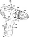
图1具有档位切换单元和通信接口的手持式工具机的立体视图,1 is a perspective view of a hand-held power tool with a gear switch unit and a communication interface,

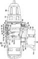
图2具有驱动单元的图1的手持式工具机的部分剖开的侧视图,FIG. 2 is a side view in partial section of the hand-held power tool of FIG. 1 with a drive unit,

图3图1和图2的手持式工具机的驱动单元的纵截面,FIG. 3 is a longitudinal section of the drive unit of the hand-held power tool of FIGS. 1 and 2,

图4具有位置探测单元的图2的档位切换单元的立体部分视图,4 is a perspective partial view of the gear switching unit of FIG. 2 with a position detection unit,

图5图2和图4的位置探测单元的分解视图,Figure 5 is an exploded view of the position detection unit of Figures 2 and 4,

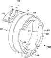
图6根据第一实施方式的、配属于图4和图5的位置探测单元的切换环的立体侧视图,FIG. 6 is a perspective side view of the switching ring associated with the position detection unit of FIGS. 4 and 5 according to the first embodiment,

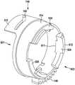
图7具有根据第二实施方式的切换环的、图4的档位切换单元的立体侧视图,7 is a perspective side view of the gear switching unit of FIG. 4 with a switching ring according to a second embodiment,

图8图7的切换环的立体侧视图,Figure 8 is a perspective side view of the switching ring of Figure 7,

图9具有根据第二实施方式的切换环的档位切换单元的立体部分视图,9 is a perspective partial view of a gear switching unit with a switching ring according to a second embodiment,

图10由图1的手持式工具机和根据第一实施方式的操作单元组成的系统的立体视图,FIG. 10 is a perspective view of a system consisting of the hand-held power tool of FIG. 1 and an operating unit according to a first embodiment,

图11具有根据第二实施方式的操作单元的、图1的手持式工具机的立体部分视图,FIG. 11 is a perspective partial view of the hand-held power tool of FIG. 1 with an operating unit according to a second embodiment,

图12根据第一实施方式的操作单元的立体视图,Figure 12 is a perspective view of the operating unit according to the first embodiment,

图13具有示例性的档位切换单元和通信接口的、图1的手持式工具机的示意性线图,13 is a schematic line drawing of the hand-held power tool of FIG. 1 with an exemplary gear switching unit and a communication interface,

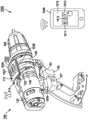
图14根据第二实施方式的档位切换单元的立体视图,Fig. 14 is a perspective view of the gear switching unit according to the second embodiment,

图15图14的档位切换单元的部分分解视图,Figure 15 is a partially exploded view of the gear shifting unit of Figure 14,

图16在未安装好的状态下的、具有根据第二实施方式的切换杆的、图14和图15的档位切换单元的立体视图,16 is a perspective view of the gear switching unit of FIGS. 14 and 15 with the switching lever according to the second embodiment in the disassembled state,

图17在安装好的状态下的、具有切换杆的、图16的档位切换单元的立体的视图,FIG. 17 is a perspective view of the gear switching unit of FIG. 16 with the switching lever in the installed state,

图18在第一档位等级中并且具有第一传感器布置的、根据第三实施方式的档位切换单元的侧视图,Figure 18 is a side view of the gear switching unit according to the third embodiment in the first gear stage and with the first sensor arrangement,

图19在第二档位等级中的、图18的档位切换单元的侧视图,Figure 19 is a side view of the gear switching unit of Figure 18 in the second gear stage,

图20在第一档位等级中并且具有第二传感器布置的、图18和图19的档位切换单元的侧视图,Figure 20 is a side view of the gear switching unit of Figures 18 and 19 in the first gear stage and with the second sensor arrangement,

图21在第二档位等级中的、图20的档位切换单元的侧视图,Figure 21 is a side view of the gear switching unit of Figure 20 in the second gear stage,

图22具有图4和图5的位置探测单元的、根据第四实施方式的档位切换单元的立体视图,Fig. 22 is a perspective view of the gear switching unit according to the fourth embodiment with the position detection unit of Figs. 4 and 5,

图23在第一档位等级中的、图22的档位切换单元的侧视图,Figure 23 is a side view of the gear switching unit of Figure 22 in the first gear stage,

图24在第二档位等级中的、图22和图23的档位切换单元的侧视图,Figure 24 is a side view of the gear switching unit of Figures 22 and 23 in the second gear stage,

图25图22至图24的档位切换单元的立体侧视图,和Fig. 25 is a perspective side view of the range switching unit of Figs. 22-24, and

图26没有传动装置壳体的、图22至图25的档位切换单元的立体视图。Figure 26 is a perspective view of the gear shifting unit of Figures 22 to 25 without the transmission housing.

具体实施方式Detailed ways

图1示出具有壳体110的示例性的手持式工具机100,在所述壳体中布置有至少一个驱动马达(图2中的120),用于驱动可布置在工具接收部190中的、优选可替换的插入式工具。在此,壳体110具有带有手动切换器105的手柄103。驱动马达(图2中的120)例如能够通过手动切换器105操纵、即接通和关断,并且优选地能够电子式地控制或者调节为不但能够实现反向运行,而且能够实现预先给定所希望的旋转速度。此外,在手动切换器105的区域中优选地布置有旋转方向切换器106,可选地,通过所述旋转方向切换器能够调节驱动马达(图2中的120)的旋转方向或者配属于该驱动马达的从动轴(图3中的310)的旋转方向。此外,为了独立于电网地供电,手持式工具机100优选地能够与蓄电池组102连接,但是对此替代地,也能够依赖于电网地运行。FIG. 1 shows an exemplary hand-heldpower tool 100 with ahousing 110 in which at least one drive motor ( 120 in FIG. 2 ) is arranged for driving a power tool which can be arranged in thetool receptacle 190 . , preferably replaceable insert tool. Here, thehousing 110 has ahandle 103 with amanual switch 105 . The drive motor ( 120 in FIG. 2 ) can be actuated, ie switched on and off, for example by means of amanual switch 105 , and can preferably be electronically controlled or regulated so as to enable not only reverse operation but also a predetermined set of conditions. desired rotational speed. Furthermore, arotational direction switch 106 is preferably arranged in the area of themanual switch 105 , by means of which the rotational direction of the drive motor ( 120 in FIG. 2 ) can optionally be adjusted or associated with the drive The direction of rotation of the driven shaft of the motor (310 in Figure 3). Furthermore, the hand-heldpower tool 100 can preferably be connected to abattery pack 102 in order to supply power independently of the mains, but can alternatively also be operated in a mains-dependent manner.

手持式工具机100优选地具有可切换传动装置(图2中的130),所述可切换传动装置至少能够在第一档位等级和第二档位等级之间切换。优选地,手持式工具机100按照冲击钻式螺钉机或者钻式螺钉机的类型构造,其中,第一档位等级例如对应于旋拧模式,并且第二档位等级对应于钻孔模式或者冲击钻孔模式。然而也能够实现另外的档位等级,从而例如钻孔模式对应于第二档位等级,并且冲击钻式模式对应于第三档位等级等等。The hand-heldpower tool 100 preferably has a switchable transmission ( 130 in FIG. 2 ) which can be switched at least between a first gear level and a second gear level. Preferably, the hand-heldpower tool 100 is designed as a hammer drill or drill screw machine, wherein the first gear level corresponds to the screwing mode, for example, and the second gear level corresponds to the drilling mode or impact Drilling pattern. However, further gear levels can also be implemented, such that, for example, the drilling mode corresponds to the second gear level, and the hammer drilling mode corresponds to the third gear level, and so on.

根据一种实施方式,设置有至少一个使用者引导单元115,所述使用者引导单元至少构造用于调节相应的当前运行中所需要的第一档位等级或者第二档位等级。在这里,使用者引导单元115能够构造用于在第一档位等级和第二档位等级之间相应地切换的情况下进行主动和/或被动的使用者引导。在主动的使用者引导的情况下,在相应的切换过程中,优选地通过视觉的、听觉的和/或触觉的、用于切换的指示或者要求引导手持式工具机10的使用者,而在被动的使用者引导的情况下,相应的切换过程自动地被执行,并且优选地仅仅向使用者显示该切换过程。以下详细地说明主动和被动的使用者引导的示例性实现方式。According to one specific embodiment, at least oneuser guidance unit 115 is provided, which is designed at least for setting the respective first gear stage or the second gear stage required in the current operation. In this case, theuser guidance unit 115 can be designed for active and/or passive user guidance when switching between the first gear level and the second gear level accordingly. In the case of active user guidance, the user of the hand-held power tool 10 is guided during the corresponding switching process, preferably by means of visual, audible and/or tactile indications or requests for switching. In the case of passive user guidance, a corresponding switching process is carried out automatically, and preferably only this switching process is displayed to the user. Exemplary implementations of active and passive user guidance are described in detail below.

使用者引导单元115优选地具有至少一个可手动地操纵的操作单元116、117,其具有至少一个、并且如示出地是可手动地操纵的第一操作元件和第二操作元件116、117,其中,操作元件116、117构造用于发起用于使传动装置130在不同的档位等级之间切换的切换过程。优选地两个操作元件116、117中的至少一个能够构造为切换器和/或键。Theuser guidance unit 115 preferably has at least one manuallyactuable operating unit 116 , 117 with at least one, and as shown, a manually actuable first andsecond operating element 116 , 117 , In this case, the operatingelements 116 , 117 are designed to initiate a shifting process for shifting thetransmission 130 between different gear stages. Preferably at least one of the two operatingelements 116 , 117 can be configured as a switch and/or a key.

使用者引导单元115优选地具有移动计算机、例如智能手机和/或平板计算机,和/或操作元件116,117能够构造为显示屏。根据一种实施方式,使用者引导单元115至少部分地集成到手持式工具机100中和/或至少部分地构造为外部的单独的组件(图10中的1040)。在此,显示屏能够集成到手持式工具机100中和/或布置在外部。切换指示优选地能够显示在显示屏上,以便至少使手持式工具机100的使用者容易地操作和/或调节例如手持式工具机100的因应用而异的运行模式。Theuser guidance unit 115 preferably has a mobile computer, for example a smartphone and/or a tablet computer, and/or the operatingelements 116 , 117 can be designed as display screens. According to one specific embodiment, theuser guidance unit 115 is at least partially integrated into the hand-heldpower tool 100 and/or at least partially constructed as an external separate component ( 1040 in FIG. 10 ). In this case, the display screen can be integrated into the hand-heldpower tool 100 and/or arranged externally. The switching indication can preferably be displayed on a display screen in order at least for the user of the hand-heldpower tool 100 to easily operate and/or adjust, for example, an application-specific operating mode of the hand-heldpower tool 100 .

此外,手持式工具机100优选地具有通信接口1050,所述通信接口优选地设置用于与优选可由使用者操纵的使用者引导单元115通信,并且,所述通信接口构造用于至少从使用者引导单元115接收用于使传动装置130因应用而异地在两个不同的档位等级之间切换的切换指示。在此,通信接口1050至少构造用于发送控制信号到操作元件116、117中的至少一个上。在此,优选实现产生用于发起切换过程的要求,所述切换过程用于例如通过操作元件116、117中的至少一个使传动装置130在两个不同的档位等级之间切换。根据一种实施方式,通信接口1050按照无线传递模块的类型构造,尤其构造为用于借助于蓝牙标准无线地通信的无线模块。然而,传递模块也能够构造用于任意其它的、无线的和/或有线的通信,例如通过WLAN和/或LAN的通信。Furthermore, the hand-heldpower tool 100 preferably has acommunication interface 1050 which is preferably provided for communication with auser guide unit 115 , which can preferably be actuated by the user, and which is designed at least from the user Thelead unit 115 receives switching instructions for switching thetransmission 130 between two different gear levels, depending on the application. In this case, thecommunication interface 1050 is designed at least to transmit control signals to at least one of the operatingelements 116 , 117 . In this case, it is preferably implemented to generate a request for initiating a shifting process for shifting thetransmission 130 between two different gear stages, eg by means of at least one of the operatingelements 116 , 117 . According to one specific embodiment, thecommunication interface 1050 is designed as a wireless transfer module, in particular as a wireless module for wireless communication by means of the Bluetooth standard. However, the transfer module can also be configured for any other, wireless and/or wired communication, eg communication via WLAN and/or LAN.

优选在壳体110上、如示出地在工具接收部190的区域中布置有选择性工作区照明装置104,用于照明手持式工具机100的工作区。此外,所述工具接收部190优选地配有用于调节最大可传递转矩的转矩限制元件170。在此,转矩限制元件170能够按照机械式打滑离合器或者电式转矩限制器的类型构造。A selective workarea lighting device 104 is preferably arranged on thehousing 110 , as shown in the region of thetool receptacle 190 , for illuminating the work area of the hand-heldpower tool 100 . Furthermore, thetool receiver 190 is preferably equipped with atorque limiting element 170 for adjusting the maximum transmittable torque. In this case, thetorque limiting element 170 can be designed in the form of a mechanical slip clutch or an electrical torque limiter.

图2示出图1的手持式工具机100,所述手持式工具机如示出地具有带有驱动马达120和可切换传动装置130的驱动单元220。可切换传动装置130优选地具有传动装置壳体136,所述传动装置壳体如示出地由两部分组成地构造有第一传动装置壳体件和第二传动装置壳体件137、138。在此,第一传动装置壳体件137优选地面向驱动马达120地布置,并且第二传动装置壳体件138面向工具接收部190地布置。然而,传动装置壳体136也能够一体地构造或者具有多于两个传动装置壳体件。可切换传动装置130优选地按照行星齿轮传动装置的类型构造,所述行星齿轮传动装置优选地至少能够在两个不同的档位等级之间切换,并且在图3中进一步地说明。FIG. 2 shows the hand-heldpower tool 100 from FIG. 1 , which, as shown, has adrive unit 220 with adrive motor 120 and aswitchable gear 130 . Theswitchable gear 130 preferably has agear housing 136 which, as shown, is constructed in two parts with a first gear housing part and a secondgear housing part 137 , 138 . Here, the firstgear housing part 137 is preferably arranged facing thedrive motor 120 and the secondgear housing part 138 is arranged facing thetool receptacle 190 . However, thegear housing 136 can also be constructed in one piece or have more than two gear housing parts. Theswitchable transmission 130 is preferably constructed as a type of planetary gear transmission, which is preferably switchable between at least two different gear stages, and is further illustrated in FIG. 3 .

根据一种实施方式,可切换传动装置130配有档位切换单元210,所述档位切换单元构造用于使可切换传动装置130在至少两个不同的档位等级之间切换。该档位切换单元210优选地具有至少一个可操纵切换环140。此外,档位切换单元210优选得具有传递单元134。According to one specific embodiment, theswitchable transmission 130 is provided with agear shifting unit 210 which is designed to switch theswitchable transmission 130 between at least two different gear stages. Thegear switching unit 210 preferably has at least onesteerable switching ring 140 . Furthermore, the shiftposition switching unit 210 preferably has thetransmission unit 134 .

可操纵切换环140优选地至少能够在第一旋转位置和第二旋转位置之间扭转,然而对此替代地或者附加地,也能够可轴向移动地构造,如在图14至21中示例性地示出。在此,切换环140的第一旋转位置优选地相应于第一档位等级,并且第二旋转位置相应于第二档位等级。Thesteerable switching ring 140 is preferably at least rotatable between a first rotational position and a second rotational position, but can alternatively or additionally to this be configured to be axially displaceable, as exemplified in FIGS. 14 to 21 . shown. Here, the first rotational position of theswitching ring 140 preferably corresponds to the first gear stage, and the second rotational position corresponds to the second gear stage.

传递单元134优选地构造用于将对可操纵切换环140的操纵传递到传动装置130的优选可轴向移动的切换元件(图3中的350)上。传递单元134优选地具有至少一个可轴向移动的切换杆133和切换箍132,其中,切换杆133使传动装置130的可轴向移动的切换元件(图3中的350)通过切换箍132与档位切换单元210的可操纵切换环140耦合。在此,切换箍132优选地可轴向运动和/或可摆动地支承在切换杆133和可轴向移动的切换元件(图3中的350)上,并且优选地使所述切换元件预紧到预先给定的切换位置中。档位切换单元210或者切换元件(图3中的350)优选地在可切换传动装置130的运行中才切换档位等级,从而仅仅在可切换传动装置130运行时能够进行档位切换。Thetransmission unit 134 is preferably designed to transmit the actuation of theactuable switching ring 140 to a preferably axially displaceable switching element ( 350 in FIG. 3 ) of thetransmission 130 . Thetransmission unit 134 preferably has at least one axiallymovable switching rod 133 and aswitching collar 132 , wherein the switchingrod 133 connects the axially movable switching element ( 350 in FIG. 3 ) of thetransmission 130 via theswitching collar 132 to the other. Thesteerable switching ring 140 of thegear switching unit 210 is coupled. In this case, theswitching collar 132 is preferably supported axially and/or pivotably on the switchingrod 133 and on the axially movable switching element ( 350 in FIG. 3 ), and the latter is preferably preloaded into the preset switching position. Thegear switching unit 210 or the shifting element ( 350 in FIG. 3 ) preferably only switches the gear stage when theswitchable transmission 130 is in operation, so that the gear switching is only possible when theswitchable transmission 130 is in operation.

根据一种实施方式,切换环140具有操纵滑轨142,切换杆133至少区段式地配合到所述操纵滑轨中。为了简化说明,接下来仅仅说明档位切换单元210的具有至少一个可扭转的切换环140并且具有传递单元134的实施方式,所述传递单元具有可摆动的切换箍132。然而,如以上所说明地,切换环140和/或切换箍132也能够在轴向上移动。According to one embodiment, theswitching ring 140 has anactuating rail 142 into which the switchinglever 133 engages at least in sections. In order to simplify the description, only the embodiment of thegear shift unit 210 with at least onetwistable shift ring 140 and with atransmission unit 134 with apivotable shift collar 132 will be described below. However, as explained above, theswitch ring 140 and/or theswitch collar 132 can also be moved in the axial direction.

优选地,切换环140配备有位置探测单元160,所述位置探测单元构造用于探测切换环140的相应的当前切换位置。在此,如以上所说明地,切换环140优选地至少能够在第一旋转位置和第二旋转位置之间扭转,其中,第一旋转位置相应于第一档位等级,并且第二旋转位置相应于第二档位等级。位置探测单元160优选地至少能够在第一探测位置和第二探测位置之间轴向地移动,其中,第一探测位置构造用于探测第一旋转位置,并且第二探测位置构造用于探测第二旋转位置。此切换环140优选地还具有与位置探测单元160连接的滑轨144,所述滑轨构造用于在操纵可操纵切换环140时使位置探测单元160在轴向上移动。Preferably, theswitching ring 140 is equipped with aposition detection unit 160 which is designed to detect the respective current switching position of theswitching ring 140 . Here, as explained above, theswitching ring 140 is preferably at least rotatable between a first rotational position and a second rotational position, wherein the first rotational position corresponds to the first gear stage and the second rotational position corresponds to in the second gear level. Theposition detection unit 160 is preferably axially movable at least between a first detection position and a second detection position, wherein the first detection position is configured to detect the first rotational position and the second detection position is configured to detect the first detection position. Two rotational positions. Thisswitching ring 140 preferably also has aslide rail 144 connected to theposition detection unit 160 which is designed to move theposition detection unit 160 in the axial direction when thesteerable switching ring 140 is actuated.

位置探测单元160优选地具有导向元件164和显示元件162,其中,导向元件164至少区段式地配合到滑轨144中。显示元件162优选地构造用于显示可操纵切换环140的相应地探测的切换位置。Theposition detection unit 160 preferably has aguide element 164 and adisplay element 162 , wherein theguide element 164 engages at least in sections into theslide rail 144 . Thedisplay element 162 is preferably designed to display the corresponding detected switching position of theactuable switching ring 140 .

根据一种实施方式,为了探测可操纵切换环140的相应的当前切换位置或者旋转位置,位置探测单元160配有传感器。根据一种实施方式,该传感器构造为线性传感器155,并且根据另一实施方式,传感器155构造为角度传感器(图7中的710)。According to one specific embodiment, theposition detection unit 160 is equipped with sensors in order to detect the corresponding current switching position or rotational position of theactuable switching ring 140 . According to one embodiment, the sensor is configured as alinear sensor 155, and according to another embodiment, thesensor 155 is configured as an angular sensor (710 in FIG. 7).

在此,线性传感器155优选地布置在配属于位置探测单元160的电子部件150的薄板151上并且构造用于探测位置探测元件160的相应的当前探测位置。在这里,线性传感器155优选地探测位置探测单元160的显示元件162的线性运动进而间接地探测可操纵切换环140的相应的当前切换位置或者旋转位置,因为显示元件162的相应的线性位置分别相应于可操纵切换环140的所配属的切换位置或者旋转位置。在此,线性传感器155优选地配有至少一个传感器元件、如示出地是三个传感器元件152、153、154。与之相比,角度传感器(图7中的710)能够用于探测可操纵切换环140的相应的角度位置,所述角度位置直接相应于可操纵切换环140的相应的切换位置或者旋转位置。In this case, thelinear sensor 155 is preferably arranged on thesheet metal 151 of theelectronic component 150 assigned to theposition detection unit 160 and is designed to detect the corresponding current detection position of theposition detection element 160 . Here, thelinear sensor 155 preferably detects a linear movement of thedisplay element 162 of theposition detection unit 160 and thus indirectly the corresponding current switching position or rotational position of thesteerable switching ring 140 , since the corresponding linear position of thedisplay element 162 respectively corresponds to in the associated switching position or rotational position of thesteerable switching ring 140 . Here, thelinear sensor 155 is preferably equipped with at least one sensor element, threesensor elements 152 , 153 , 154 as shown. In contrast, an angle sensor ( 710 in FIG. 7 ) can be used to detect the corresponding angular position of thesteerable switching ring 140 , which directly corresponds to the corresponding switching or rotational position of thesteerable switching ring 140 .

根据一种实施方式,档位切换单元210配有具有调节马达182的调节单元180。调节马达182优选地配有调节马达传动装置184。调节马达182优选地构造用于在激活时操纵可操纵切换环140,用于在至少两个不同的档位等级之间进行档位切换。在此,优选地能够通过操纵至少一个操作元件116、117或者通过使用者引导单元115激活调节马达180。According to one embodiment, thegear switching unit 210 is equipped with anadjustment unit 180 with anadjustment motor 182 . Theadjustment motor 182 is preferably equipped with anadjustment motor transmission 184 . The regulatingmotor 182 is preferably configured to actuate, when activated, thesteerable shift ring 140 for gear shifting between at least two different gear levels. Here, theadjustment motor 180 can preferably be activated by actuating at least oneoperating element 116 , 117 or by means of theuser guide unit 115 .

通信接口1050优选地构造用于传递控制信号到调节马达182上,用于激活调节马达182。在这里,能够对至少一个操作元件116、117的操纵作出答复地产生控制信号。对此替代地或者附加地,优选地能够通过使用者引导单元115触发产生控制信号,即例如通过呈智能手机或者平板计算机形式的移动计算机触发产生控制信号,从而也能够省去提供操作元件116、117。此外,根据一种实施方式,所述产生也能够直接地被通信接口1050触发,例如根据预先给定的运行参数触发,从而又能够省去提供操作元件116、117。Thecommunication interface 1050 is preferably configured to transmit control signals to theadjustment motor 182 for activating theadjustment motor 182 . Here, control signals can be generated in response to actuation of the at least oneoperating element 116 , 117 . Alternatively or in addition to this, the generation of the control signal can preferably be triggered by theuser guidance unit 115 , ie, for example by a mobile computer in the form of a smartphone or tablet, so that the provision of the operatingelements 116 , 117. Furthermore, according to one embodiment, the generation can also be triggered directly by thecommunication interface 1050 , for example as a function of predefined operating parameters, so that the provision of the operatingelements 116 , 117 can again be dispensed with.

为了在激活调节马达182的情况下操纵可操纵切换环140,调节单元180优选地具有从动轴186,所述从动轴优选地驱动切换环140的驱动元件146。从动轴186和驱动元件146优选地构造为齿轮,所述齿轮相互啮合。从动轴186和驱动元件146的相应齿部优选地以直齿的方式构造,以便通过从动轴186的扭转实现切换环140的扭转。由此,优选地能够实现切换环140在至少两个旋转位置之间扭转。根据一种实施方式,能够通过位置探测单元160的电子部件150控制调节马达182,其中,优选地在电源切断(例如蓄电池更换)之后能够通过位置探测单元160求取当前的切换环位置。In order to actuate thesteerable switching ring 140 with activation of the adjustingmotor 182 , the adjustingunit 180 preferably has anoutput shaft 186 which preferably drives thedrive element 146 of theswitching ring 140 . Theoutput shaft 186 and thedrive element 146 are preferably configured as gears which mesh with each other. The corresponding toothings of theoutput shaft 186 and thedrive element 146 are preferably designed in the manner of straight teeth, in order to achieve a twisting of theswitching ring 140 by twisting theoutput shaft 186 . Thereby, a twisting of theswitching ring 140 between at least two rotational positions is preferably possible. According to one specific embodiment, the regulatingmotor 182 can be controlled by theelectronic component 150 of theposition detection unit 160 , wherein the current switching ring position can be ascertained by theposition detection unit 160 , preferably after a power disconnection (eg battery replacement).

此外,图2说明了手持式工具机100的手动切换器105,所述手动切换器构造用于激活和停用驱动马达120。在此,手动切换器105优选地配有接通/关断切换器107,其中,手动切换器105优选地构造为按钮,然而也可以构造为键。Furthermore, FIG. 2 shows amanual switch 105 of the hand-heldpower tool 100 which is designed to activate and deactivate thedrive motor 120 . Here, themanual switch 105 is preferably equipped with an on/offswitch 107 , wherein themanual switch 105 is preferably designed as a button, but can also be designed as a key.

图3示出优选地构造为行星齿轮传动装置的、图1和图2的可切换传动装置130,用于驱动图1的手持式工具机100的从动轴310。行星齿轮传动装置130优选地具有至少一个第一行星齿轮级和第二行星齿轮级,如示出地是第一行星齿轮级、第二行星齿轮级和第三行星齿轮级372、374、376,如示出地,所述第一行星齿轮级、第二行星齿轮级和第三行星齿轮级实现行星齿轮传动装置130在第一档位等级和第二档位等级中的运行。在此,各个档位等级优选地对应于相应的运行模式,例如旋拧模式、钻孔模式和/或冲击钻式模式/冲击式旋拧模式。例如旋拧模式能够设置用于在第一档位等级中实施具有转矩限制的旋拧过程,而钻孔过程和/或具有冲击功能的钻孔过程或者旋拧过程设置用于在第二档位等级中实施。FIG. 3 shows theswitchable gear 130 of FIGS. 1 and 2 , preferably designed as a planetary gear, for driving theoutput shaft 310 of the hand-heldpower tool 100 of FIG. 1 . Theplanetary gear arrangement 130 preferably has at least one first and second planetary gear stages, such as the first, second and third planetary gear stages 372 , 374 , 376 as shown, As shown, the first, second, and third planetary gear stages enable operation of theplanetary gear arrangement 130 in the first and second gear stages. In this case, the individual gear stages preferably correspond to a corresponding operating mode, for example a screwing mode, a drilling mode and/or a hammer drilling mode/percussion screwing mode. For example, the screwing mode can be set for carrying out a torque-limited screwing process in a first gear level, while a drilling process and/or a drilling process or screwing process with a percussion function can be set for the second gear stage. implemented at the bit level.

行星齿轮传动装置130优选地具有可轴向移动的切换元件350,所述切换元件优选地构造为切换空心轮并且接下来被称作“切换空心轮350”。该切换空心轮350优选地能够在至少两个轴向位置之间移动,其中,一个轴向位置分别对应于一个档位等级。根据一种实施方式,切换空心轮350构造为第二行星齿轮传动级的空心轮,然而替代地,切换空心轮350也能够构造为行星齿轮传动装置130的附加切换空心轮。Theplanetary gear 130 preferably has an axiallydisplaceable shifting element 350 which is preferably designed as a shifting ring gear and is hereinafter referred to as “shift ring gear 350 ”. The shiftingring gear 350 is preferably movable between at least two axial positions, wherein each axial position corresponds to a gear stage. According to one embodiment, the shiftingring gear 350 is designed as a ring gear of the second planetary gear stage, but alternatively, the shiftingring gear 350 can also be designed as an additional shifting ring gear of theplanetary gear 130 .

此外,图3说明了传递单元134与行星齿轮传动装置130的连接,其中,传递单元134优选地构造用于将可操纵切换环140的操纵传递到行星齿轮传动装置130的可轴向移动的切换空心轮350。在这里,配属于传递单元134的切换杆133优选地使行星齿轮传动装置130的切换空心轮350通过切换箍132与档位切换单元210的可操纵切换环140连接。切换箍132优选地可摆动地支承在切换杆133和可轴向移动的切换空心轮350上。优选地在切换空心轮350和行星齿轮传动装置130之间齿挨齿布置的情况下能够进行档位切换。Furthermore, FIG. 3 illustrates the connection of thetransmission unit 134 to theplanetary gear 130 , wherein thetransmission unit 134 is preferably configured to transmit the actuation of theactuable switching ring 140 to the axially displaceable switching of theplanetary gear 130 .Hollow wheel 350. Here, theshift lever 133 assigned to thetransmission unit 134 preferably connects theshift ring gear 350 of theplanetary gear 130 via theshift collar 132 with theactuable shift ring 140 of thegear shift unit 210 . Theswitching collar 132 is preferably pivotably mounted on the switchingrod 133 and the axially displaceableswitching ring gear 350 . Gear shifting is preferably possible with the tooth-to-tooth arrangement between the switchingring gear 350 and theplanetary gear 130 .

此外,图3说明了一种选择性冲击机构,如示出地构造为卡锁式冲击机构的冲击机构320,所述冲击机构优选地能够在冲击钻孔模式下激活。然而要指出,冲击机构320作为卡锁式冲击机构的构型具有仅仅示例性的特征并且不可视为对本发明的限制。冲击机构320也可以构造为任意的其它的冲击机构,例如构造为摆动式冲击机构。为了激活和/或停用冲击机构320或者相应的冲击模式,设置有锁止元件330,所述锁止元件在冲击模式下在可操纵切换环140的面向工具接收部190的端部上被切换环140的停用元件342加载。在此,切换环140在其面向传动装置130的端部344上优选地停靠在壳体110上或者停靠在传动装置壳体136上。Furthermore, FIG. 3 illustrates a selective percussion mechanism, such aspercussion mechanism 320 shown configured as a latching percussion mechanism, which is preferably activatable in percussion drilling mode. It should be pointed out, however, that the configuration of theimpact mechanism 320 as a latching impact mechanism is of a purely exemplary character and should not be considered a limitation of the present invention. Thestriking mechanism 320 can also be designed as any other striking mechanism, for example as a pivoting striking mechanism. In order to activate and/or deactivate thestriking mechanism 320 or the corresponding striking mode, a blockingelement 330 is provided, which is switched in the striking mode at the end of theactuable switching ring 140 facing thetool receptacle 190 . Thedeactivation element 342 of thering 140 is loaded. In this case, theswitching ring 140 preferably rests on thehousing 110 or on thegear housing 136 at itsend 344 facing thetransmission 130 .

图4示出图2的具有切换杆133和切换箍132的传递单元134。如示出地,切换杆133具有第一轴向端部和第二轴向端部431、433,其中,示例性地,第一端部431面向驱动马达120,并且第二端部433面向转矩限制元件170。FIG. 4 shows thetransmission unit 134 of FIG. 2 with theswitch lever 133 and theswitch collar 132 . As shown, theswitch lever 133 has first and second axial ends 431 , 433 , wherein, by way of example, thefirst end 431 faces thedrive motor 120 and thesecond end 433 faces the rotationTorque limiting element 170 .

切换环133优选地布置在传动装置壳体136的(在图4中如示出地在上方的)导向区域416中,其中,切换杆133的第二端部433布置在切换环140和传动装置壳体136之间或者布置在切换环140的面向传动装置壳体136的侧上。在此,切换杆133优选地以其布置在第二端部433上的导向元件(图9中的921)至少区段式地作用到可操纵切换环140的操纵滑轨142中。切换杆133在其第一端部431上具有用于接收切换箍132的、优选槽式的接收部434。Theswitching ring 133 is preferably arranged in a guide region 416 (shown above in FIG. 4 ) of thegear housing 136 , wherein thesecond end 433 of the switchinglever 133 is arranged between the switchingring 140 and the gear. Between thehousings 136 or on the side of theswitching ring 140 facing thegear housing 136 is arranged. In this case, the switchinglever 133 preferably acts with its guide element ( 921 in FIG. 9 ) arranged on thesecond end 433 at least in sections into theactuating slide 142 of theactuable switching ring 140 . On itsfirst end 431 , theswitch lever 133 has a preferably slot-like receptacle 434 for receiving theswitch collar 132 .

根据一种实施方式,为了布置在切换杆133的槽式接收部434中,切换箍132具有接收区域423。接收区域423优选地通过连接区域422与端部区域421连接。在此,为了布置在切换空心轮350上,端部区域421优选地通过传动装置壳体136的槽口414穿过传动装置壳体136。According to one embodiment, theswitching collar 132 has a receivingarea 423 for arrangement in the slot-like receptacle 434 of the switchinglever 133 . The receivingarea 423 is preferably connected to theend area 421 via the connectingarea 422 . In this case, theend region 421 preferably passes through thegear housing 136 through therecess 414 of thegear housing 136 for the arrangement on theswitching ring gear 350 .

切换箍132优选地在连接区域422的区域中通过传动装置壳体136的至少一个导向接片、如示出地是第一导向接片和第二导向接片411、412导向。切换箍132优选地至少接近U形地构造,其中,在图4中仅仅示出切换箍132的一侧,并且其中,相对置的侧优选地类似于在图4中所示出的侧构造。此外,切换箍132优选地构造为线材切换箍。Theswitching collar 132 is preferably guided in the region of the connectingregion 422 by at least one guide web of thetransmission housing 136 , as shown, the first andsecond guide webs 411 , 412 . Theswitching collar 132 is preferably at least approximately U-shaped, wherein only one side of theswitching collar 132 is shown in FIG. 4 , and wherein the opposite side is preferably configured similarly to the side shown in FIG. 4 . Furthermore, the switchingferrule 132 is preferably configured as a wire switching ferrule.

图5示出具有显示元件162和导向元件164的图2的位置探测单元160,其中,显示元件162优选地布置在位置探测单元160的上侧503上,并且导向元件164布置在其下侧504上。在此,上侧503如示出地面向薄板151的下侧502,并且在薄板151的上侧501上布置有优选地构造为线性传感器的传感器155。薄板151优选地具有槽口532,位置探测单元160的显示元件162穿过所述槽口伸出,用于显示可操纵切换环140的相应地探测的切换位置。此外,图5说明了导向元件164在可操纵切换环140的滑轨144中的至少区段式地布置。在此,切换环140优选地面向位置探测单元160的下侧504。FIG. 5 shows theposition detection unit 160 of FIG. 2 with adisplay element 162 and aguide element 164 , wherein thedisplay element 162 is preferably arranged on theupper side 503 of theposition detection unit 160 and theguide element 164 is arranged on itslower side 504 superior. Here, theupper side 503 faces, as shown, thelower side 502 of thelamella 151 , and on theupper side 501 of the lamella 151 asensor 155 , which is preferably designed as a linear sensor, is arranged. Thesheet 151 preferably has aslot 532 through which thedisplay element 162 of theposition detection unit 160 protrudes for displaying the correspondingly detected switching position of thesteerable switching ring 140 . Furthermore, FIG. 5 illustrates the at least segmental arrangement of theguide elements 164 in theslide rail 144 of thesteerable switching ring 140 . Here, theswitching ring 140 preferably faces theunderside 504 of theposition detection unit 160 .

根据一种实施方式,可操纵切换环140具有优选柱形的基体514,所述基体具有第一轴向端部和第二轴向端部521、522以及外周缘和内周缘515、516。基体514优选地至少区段式地具有轴向的扩展区域512,所述扩展区域优选地构造在切换环140的第一端部521上,然而也可以构造在第二端部522上。在此,扩展区域512优选地弧形地构造并且根据第一实施方式设有滑轨144和操纵滑轨142。在此,所述滑轨144如示出地比所述操纵滑轨142更靠近第一端部521地布置。然而,也可以是操纵滑轨142比滑轨144更靠近第一端部521地布置。According to one embodiment, thesteerable switching ring 140 has a preferablycylindrical base body 514 with first and second axial ends 521 , 522 and outer andinner peripheries 515 , 516 . Thebase body 514 preferably has anaxial expansion region 512 at least in sections, which is preferably formed on thefirst end 521 of theswitching ring 140 , but can also be formed on thesecond end 522 . In this case, theexpansion area 512 is preferably arc-shaped and, according to the first embodiment, is provided with theslide rail 144 and theactuating slide rail 142 . Here, theslide rail 144 is, as shown, arranged closer to thefirst end 521 than theactuating slide rail 142 . However, it is also possible that theactuating slide rail 142 is arranged closer to thefirst end 521 than theslide rail 144 .

此外,基体514优选地在其外周缘515上具有用于通过图2的调节单元180驱动切换环140的驱动元件146。驱动元件146优选地构造为圆形的或者扇段状的齿轮元件或者说小齿轮元件。此外,优选在基体514的轴向端部522上布置有至少一个凸台并且如示出地是三个凸台524、526、528,用于停用冲击机构320和/或用于进行转矩限制,所述凸台示例性地构成图3的停用元件342。Furthermore, thebase body 514 preferably has adrive element 146 on itsouter periphery 515 for driving theswitching ring 140 via theadjusting unit 180 of FIG. 2 . Thedrive element 146 is preferably designed as a circular or segment-shaped gear element or pinion element. Furthermore, preferably at least one boss and, as shown, threebosses 524 , 526 , 528 are arranged on theaxial end 522 of thebase body 514 for deactivating theimpact mechanism 320 and/or for applying torque By way of limitation, the boss exemplarily constitutes thedeactivation element 342 of FIG. 3 .

图6示出图5的切换环140,所述切换环按照第一实施方式构造并且优选地具有三个凸台元件524、526、528。在此,凸台元件524、526、528中的每个优选地具有至少一个轴向的扩展部611、612,其中,第一扩展部611朝向切换环140的第一端部521的方向构造,并且第二扩展部612朝向切换环140的第二端部522的方向构造。根据一种实施方式,第一扩展部611构造用于转矩限制,并且第二扩展部612构造用于停用冲击机构320。FIG. 6 shows theswitching ring 140 of FIG. 5 , which is constructed according to the first embodiment and preferably has threeboss elements 524 , 526 , 528 . Here, each of theboss elements 524 , 526 , 528 preferably has at least oneaxial extension 611 , 612 , wherein thefirst extension 611 is formed in the direction of thefirst end 521 of theswitching ring 140 , And thesecond expansion portion 612 is configured toward the direction of thesecond end portion 522 of theswitching ring 140 . According to one embodiment, thefirst extension 611 is configured for torque limiting and thesecond extension 612 is configured for deactivating theimpact mechanism 320 .

图7示出具有根据第二实施方式的可操纵切换环740的、而不包括第一传动装置壳体件137的、图2的档位切换单元210。在此,可操纵切换环740类似于图1至图6的切换环140地构造,然而扩展部512仅仅具有操纵滑轨142。此外,用于探测可操纵切换环740的相应的当前切换位置的位置探测单元740优选地配有构造为角度传感器710的传感器155。如示出地,角度传感器710布置在调节单元180的区域中、尤其布置在从动元件186上。然而,角度传感器710也可以布置在切换环740的区域中。FIG. 7 shows thegear shifting unit 210 of FIG. 2 without the firsttransmission housing part 137 with theactuable shifting ring 740 according to the second embodiment. In this case, theactuable switching ring 740 is constructed similarly to theswitching ring 140 of FIGS. 1 to 6 , however theextension 512 has only theactuating rail 142 . Furthermore, theposition detection unit 740 for detecting the respective current switching position of thesteerable switching ring 740 is preferably equipped with asensor 155 designed as anangle sensor 710 . As shown, theangle sensor 710 is arranged in the region of theadjustment unit 180 , in particular on theoutput element 186 . However, theangle sensor 710 can also be arranged in the region of theswitching ring 740 .

图8示出图7的可操纵切换环740,具有所述可操纵切换环的第一端部和第二端部821、822,其中,扩展区域512类似于图1至图6的可操纵切换环140地布置在切换环740的第一端部821上。在此,图8说明了具有操纵滑轨142的扩展区域512。FIG. 8 shows thesteerable switching ring 740 of FIG. 7 with first and second ends 821 , 822 of the steerable switching ring, wherein theexpansion area 512 is similar to the steerable switching of FIGS. 1-6 Thering 140 is arranged on thefirst end 821 of theswitching ring 740 . Here, FIG. 8 illustrates theextended area 512 with thesteering rail 142 .

图9示出具有图7和图8的可操纵切换环740的、图2的档位切换单元210,并且说明了一种构造在切换杆133的第二端部433上的导向元件921,为了进行档位切换,所述导向元件能够至少区段式地布置在操纵滑轨142中。根据另一实施方式,切换环740的扩展区域512具有第一止挡边沿和第二止挡边沿931、932。此外,第一传动装置壳体件137具有至少一个止挡元件,如示出地是两个止挡元件911、912。在此,第二止挡边沿932优选地在图9中的切换环740的示出的旋转位置(该旋转位置例如相应于旋拧模式)中示例性地贴靠在第二止挡元件912上,并且第一止挡边沿931面向第一止挡元件911,其中,第一止挡边沿931在切换环740的另外的旋转位置(该另外的旋转位置相应于冲击模式)中会贴靠在第一止挡元件911上。FIG. 9 shows thegear shift unit 210 of FIG. 2 with theactuable shift ring 740 of FIGS. 7 and 8 and illustrates aguide element 921 formed on thesecond end 433 of theshift lever 133 for the purpose of For gear shifting, the guide element can be arranged at least in sections in theactuating rail 142 . According to a further embodiment, the expandedregion 512 of theswitching ring 740 has a first stop edge and asecond stop edge 931 , 932 . Furthermore, the firsttransmission housing part 137 has at least one stop element, as shown, twostop elements 911 , 912 . In this case, thesecond stop edge 932 preferably rests on thesecond stop element 912 in the illustrated rotational position of theswitching ring 740 in FIG. 9 , which corresponds, for example, to the screwing mode. , and thefirst stop edge 931 faces thefirst stop element 911 , wherein thefirst stop edge 931 in a further rotational position of theswitching ring 740 , which corresponds to the impact mode, abuts on astop element 911 .

图10示出具有图2的档位切换单元210的、图1的手持式工具机100,根据一种实施方式,所述档位切换单元具有图7的可操纵切换环140和调节单元180以及图1的通信接口1050。此外,手持式工具机100设有图1的使用者引导单元115,在这里,所述使用者引导单元优选地具有用于手动地调节档位等级或者运行模式的操作单元1020。FIG. 10 shows the hand-heldpower tool 100 of FIG. 1 with thegear shifting unit 210 of FIG. 2 , which, according to one embodiment, has theactuable shifting ring 140 and the adjustingunit 180 of FIG. 7 andCommunication interface 1050 of FIG. 1 . Furthermore, the hand-heldpower tool 100 is provided with auser guide unit 115 from FIG. 1 , which preferably has anoperating unit 1020 for manually adjusting the gear level or operating mode.

操作单元1020优选地设有至少一个操作元件,如示出地是三个操作元件1021、1022、1023,用于调节档位等级或者运行模式。如示出地,操作元件1021设置用于调节旋拧模式,操作元件1022设置用于调节钻孔模式,并且操作元件1023设置用于调节冲击模式,其中,操作元件1021-1023示例性地具有与运行模式相应的符号。操作元件1021-1023优选地布置在薄板1030上。在此,操作单元1020优选地至少部分地集成到手持式工具机100中。Theoperating unit 1020 is preferably provided with at least one operating element, three operatingelements 1021 , 1022 , 1023 as shown, for adjusting the gear stage or operating mode. As shown, theoperating element 1021 is provided for adjusting the screwing mode, theoperating element 1022 is provided for adjusting the drilling mode, and theoperating element 1023 is provided for adjusting the striking mode, wherein the operating elements 1021 - 1023 exemplarily have the same Symbols corresponding to the operating mode. The operating elements 1021 - 1023 are preferably arranged on thethin plate 1030 . In this case, theoperating unit 1020 is preferably at least partially integrated into the hand-heldpower tool 100 .

在这里或者对此替代地,使用者引导单元115能够如以上所说明地至少部分地构造为外部的、单独的组件1040。在这种情况下,外部的组件1040优选地具有移动计算机,尤其按照智能手机和/或平板计算机的类型构造的移动计算机。对此替代地,也能够使用其它的所谓的“智能设备”(例如表、眼镜等等)作为移动计算机。在此,如以上所说明的,也能够省去提供操作单元1020,尤其在所述操作单元能够由移动计算机实现的情况下。为了显示所调节的运行模式,手持式工具机100优选地具有显示屏。在这种情况下,使用者引导单元115优选地与手持式工具机100构成工具系统1000。Here or as an alternative to this, theuser guide unit 115 can, as explained above, be at least partially configured as an external,separate component 1040 . In this case, theexternal component 1040 preferably has a mobile computer, in particular a mobile computer designed in the form of a smartphone and/or a tablet computer. Alternatively to this, other so-called "smart devices" (eg watches, glasses, etc.) can also be used as mobile computers. Here, as explained above, the provision of theoperating unit 1020 can also be omitted, especially if the operating unit can be implemented by a mobile computer. In order to display the set operating mode, the hand-heldpower tool 100 preferably has a display screen. In this case, theuser guidance unit 115 preferably forms atool system 1000 with the hand-heldpower tool 100 .

移动计算机1040优选地具有显示屏1010,所述显示屏优选地按照触摸屏的类型构造或者构造用于手势控制。为了输入手持式工具机100的至少一种运行模式,显示屏1010优选地具有至少一个操作元件,如示出地是三个操作元件1011、1012、1013。如示出地,在图10中,操作元件1011-1013在显示屏1010上构造为操作区,然而也能够构造为切换器和/或键。Themobile computer 1040 preferably has adisplay screen 1010, which is preferably constructed as a touch screen or for gesture control. In order to enter at least one operating mode of the hand-heldpower tool 100 , thedisplay screen 1010 preferably has at least one operating element, as shown, three operatingelements 1011 , 1012 , 1013 . As shown in FIG. 10 , the operating elements 1011 - 1013 are configured as operating fields on thedisplay screen 1010 , but can also be configured as switches and/or keys.

在使用者引导单元115不但包括操作单元1020而且包括移动计算机1040的情况下,以上所说明的控制信号优选地构造用于在显示屏1010上产生用于下述要求的显示,所述要求用于发起用于使传动装置130在不同的档位等级之间切换的切换过程。在这里,优选通过显示屏1010上显示指示,所述指示例如是应设置哪种运行模式用于预先给定的工作流程,随后手持式工具机100的使用者例如能够通过操作单元1020调节所述运行模式。在此,在手持式工具机100上的操作元件1021-1023能够设有照明器件(图12中的1231、1232、1233),并且在这种情况下,控制信号构造用于分别激活相应的照明器件(图12中的1231、1232、1233)。In the case where theuser guidance unit 115 includes both theoperating unit 1020 and themobile computer 1040 , the control signals described above are preferably designed to generate a display on thedisplay screen 1010 for the request for A shift process for shifting thetransmission 130 between different gear levels is initiated. In this case, an indication is preferably displayed ondisplay screen 1010 , for example, which operating mode should be set for a predetermined work sequence, and the user of hand-heldpower tool 100 can then adjust said operation, for example, viaoperating unit 1020 . run mode. In this case, the operating elements 1021 - 1023 on the hand-heldpower tool 100 can be provided with lighting means ( 1231 , 1232 , 1233 in FIG. 12 ), and in this case the control signals are designed to activate the respective lighting in each case devices (1231, 1232, 1233 in Figure 12).

此外,移动计算机1040也能够至少部分地集成到手持式工具机100中,并且,运行模式的调节优选分别自动地、优选通过调节单元180进行。要指出,使用者引导单元115的在图10中所说明的示例性实现方式能够任意地相互组合,并且例如通信接口1050也能够承担使用者引导单元115的功能。Furthermore, themobile computer 1040 can also be integrated at least partially into the hand-heldpower tool 100 , and the adjustment of the operating mode is preferably carried out automatically, preferably via theadjustment unit 180 . It is pointed out that the exemplary implementations of theuser guidance unit 115 illustrated in FIG. 10 can be combined with one another as desired, and for example thecommunication interface 1050 can also assume the function of theuser guidance unit 115 .

图11示出图10的操作单元1020,根据一种实施方式,所述操作单元具有用于手动地调节相应的运行模式的调节元件1120。在此,调节元件1120优选地与图2至图6的可操纵切换环140或者图7至图10的可操纵切换环740一体地构造并且优选地穿过操作单元1020的槽口1105伸出。通过调节元件1120在双箭头1103的方向上的移动使切换环140或者切换环740扭转,由此能够调节相应的运行模式。类似于图10地,操作元件1021-1023具有与相应的运行模式相应的符号。FIG. 11 shows theoperating unit 1020 of FIG. 10 , which, according to one embodiment, has anadjusting element 1120 for manually adjusting the corresponding operating mode. In this case, theadjustment element 1120 is preferably formed integrally with theactuable switching ring 140 of FIGS. 2 to 6 or theactuable switching ring 740 of FIGS. 7 to 10 and preferably protrudes through theslot 1105 of theoperating unit 1020 . By shifting theadjusting element 1120 in the direction of thedouble arrow 1103 , theswitching ring 140 or theswitching ring 740 is twisted, as a result of which the corresponding operating mode can be adjusted. Similar to FIG. 10 , the operating elements 1021 - 1023 have symbols corresponding to the respective operating modes.

图12示出具有操作元件1021-1023以及薄板1030的、图10的操作单元1020。在此,所述薄板1030优选地具有至少一个切换元件,并且如示出地是三个切换元件1235、1236、1237。为了显示分别调节的档位等级,优选地设置有三个显示元件1231、1232、1233。所述显示元件优选地构造为照明元件。在这里,具有照明元件1231-1233的切换元件1235-1237分别配属于操作元件1021-1023。如示出地,切换元件1235和照明元件1231配属于操作元件1021,切换元件1236和照明元件1232配属于操作元件1022,并且切换元件1237和照明元件1233配属于操作元件1023。FIG. 12 shows theoperating unit 1020 of FIG. 10 with operating elements 1021 - 1023 andsheet 1030 . Here, thesheet 1030 preferably has at least one switching element, and as shown, three switchingelements 1235 , 1236 , 1237 . In order to display the respectively adjusted gear level, preferably threedisplay elements 1231 , 1232 , 1233 are provided. The display elements are preferably designed as lighting elements. Here, the switching elements 1235-1237 with the lighting elements 1231-1233 are respectively assigned to the operating elements 1021-1023. As shown, switchingelement 1235 andlighting element 1231 are assigned tooperating element 1021 , switchingelement 1236 andlighting element 1232 are assigned tooperating element 1022 , and switchingelement 1237 andlighting element 1233 are assigned tooperating element 1023 .

优选地至少能够激活照明器件1231、1232、1233,用于显示用于发起切换过程的要求,所述切换过程用于使图2的传动装置130在不同的档位等级之间切换。切换元件1235-1237优选地构造为切换器或者键,和/或照明元件1231-1233按照发光二极管的类型构造。替代地,操作单元1020也能够按照显示屏的类型(优选地以触摸屏的方式)构造和/或按照移动计算机的类型构造,其中,在显示屏上的分别要操纵的符号能够分别亮起来和/或发出闪光。操作单元1020优选地与调节单元180或者说调节马达182和调节马达传动装置184连接,用于调节由使用者1230选择的运行模式或者说用于使图2至6的可操纵切换环140扭转,所述切换环又能够使位置探测单元160优选地沿着双箭头1201在轴向上移动。Preferably at least the lighting means 1231, 1232, 1233 can be activated for displaying a request for initiating a shifting process for shifting thetransmission 130 of Figure 2 between different gear levels. The switching elements 1235-1237 are preferably constructed as switches or keys, and/or the lighting elements 1231-1233 are constructed in the type of light-emitting diodes. Alternatively, theoperating unit 1020 can also be designed as a display screen (preferably in the form of a touch screen) and/or as a mobile computer, wherein the symbols on the display screen to be actuated in each case can be individually illuminated and/or or flash. Theoperating unit 1020 is preferably connected to theadjusting unit 180 or the adjustingmotor 182 and the adjustingmotor gear 184 for adjusting the operating mode selected by theuser 1230 or for rotating theactuable switching ring 140 of FIGS. 2 to 6 , Said switching ring in turn enables theposition detection unit 160 to be moved in the axial direction, preferably along thedouble arrow 1201 .

图13示出图10的工具系统1000,具有图10的手持式工具机100和移动计算机1040。在此,图13说明了手持式工具机100,所述手持式工具机具有其驱动单元220,所述驱动单元具有驱动马达120、传动装置130、冲击机构320以及转矩限制元件170。在此,电子部件150控制至少一个致动器1351、1352、1353。如示出地,在图13中示出三个致动器1351、1352、1353,其中,致动器1351示例性地构造用于传动装置130的档位切换,致动器1352构造用于激活/停用冲击机构320,并且致动器1353构造用于借助于转矩限制元件170调节转矩。优选地,在致动器1351-1353激活时,电子部件150传递激活信号到所配属的照明元件1231-1233上。替代地或者附加地,激活信号也可以构造为铃声。FIG. 13 shows thetool system 1000 of FIG. 10 with the hand-heldpower tool 100 of FIG. 10 and themobile computer 1040 . Here, FIG. 13 shows the hand-heldpower tool 100 with itsdrive unit 220 with thedrive motor 120 , thegear 130 , theimpact mechanism 320 and thetorque limiting element 170 . Here, theelectronic component 150 controls at least oneactuator 1351 , 1352 , 1353 . As shown, threeactuators 1351 , 1352 , 1353 are shown in FIG. 13 , wherein theactuator 1351 is configured by way of example for gear shifting of thetransmission 130 and theactuator 1352 is configured for activating Theimpact mechanism 320 is deactivated, and theactuator 1353 is configured to adjust the torque by means of thetorque limiting element 170 . Preferably, when the actuators 1351-1353 are activated, theelectronic component 150 transmits an activation signal to the associated lighting elements 1231-1233. Alternatively or additionally, the activation signal can also be designed as a ringtone.

根据一种实施方式,移动计算机1040具有交互程序1342、1344,尤其具有智能手机App,用于与手持式工具机100的通信接口1050通信。在此,第一程序1342优选地构造用于设置应用情况,例如将螺钉拧入软木中。在这里,程序1342优选针对相应的应用情况确定运行参数,例如转速、旋转方向、转矩、档位等级和/或冲击式运行要求,并且将这些运行参数传递到手持式工具机100的通信接口1050上。According to one specific embodiment, themobile computer 1040 hasinteraction programs 1342 , 1344 , in particular a smartphone app, for communicating with thecommunication interface 1050 of the hand-heldpower tool 100 . Here, thefirst procedure 1342 is preferably configured for setting the application, such as screwing a screw into a cork. In this case,program 1342 preferably determines operating parameters, such as rotational speed, direction of rotation, torque, gear level and/or impact operating requirements for the respective application, and transmits these operating parameters to the communication interface of hand-heldpower tool 100 1050 on.

在这里,通信接口1050优选地构造用于将控制信号传递到手持式工具机100的致动器1351、1352、1353上,其中,至少一个致动器1351构造用于在被通信接口1050激活时使传动装置130在不同的档位等级之间切换。在此,通信接口1050优选地传递控制信号到下述电子部件150上,所述电子部件激活和/或控制相应的致动器1351-1353。In this case, thecommunication interface 1050 is preferably designed to transmit control signals to theactuators 1351 , 1352 , 1353 of the hand-heldpower tool 100 , wherein the at least oneactuator 1351 is designed to be activated by thecommunication interface 1050 . Thetransmission 130 is switched between different gear levels. Here, thecommunication interface 1050 preferably transmits control signals to theelectronic components 150 described below, which activate and/or control the corresponding actuators 1351-1353.

替代地或者附加地,设置有第二程序1344,所述第二程序构造用于调节至少一个确定的运行参数,例如转速、旋转方向、转矩、档位等级和/或冲击式运行要求。在这里,手持式工具机100的使用者直接通过程序1344输入所希望的运行参数。然后所述运行参数传送到手持式工具机100的通信接口1050上,其中,通信接口1050如以上所说明地传递相应的控制信号。Alternatively or additionally, asecond program 1344 is provided, which is designed to adjust at least one specific operating parameter, such as rotational speed, rotational direction, torque, gear level and/or a shock operating request. Here, the user of hand-heldpower tool 100 directly enters desired operating parameters viaprogram 1344 . The operating parameters are then transmitted to thecommunication interface 1050 of the hand-heldpower tool 100 , wherein thecommunication interface 1050 transmits the corresponding control signals as described above.

对此替代地或者附加地,手持式工具机100能够具有至少一个信号发送器1311、1312、1313,用于手动地调节档位等级和/或运行模式或者说用于手动地调节运行参数。如示出地,在图13中示出三个信号发送器1311、1312、1313。在此,第一信号发送器1311示例性地构造用于档位切换,第二信号发送器1312构造用于激活和/或停用冲击机构320,并且第三信号发送器1313构造用于转矩调节。相应的信号发送器1311-1313优选地构造用于因应用而异地或者根据输入地发送控制信号到电子部件150上,使得电子部件150能够激活和/或控制相应的致动器1351-1353。在此,信号发送器1311-1313优选地构造为电信号发送器,然而也能够构造为任意的其它的信号发送器,例如构造为可机械式移动的杠杆臂。Alternatively or in addition to this, the hand-heldpower tool 100 can have at least onesignal transmitter 1311 , 1312 , 1313 for manually setting the gear stage and/or the operating mode or for manually setting the operating parameters. As shown, threesignal transmitters 1311 , 1312 , 1313 are shown in FIG. 13 . Here, thefirst signal transmitter 1311 is designed by way of example for gear shifting, thesecond signal transmitter 1312 is designed for activating and/or deactivating theimpact mechanism 320 , and thethird signal transmitter 1313 is designed for torque adjust. The respective signal transmitters 1311-1313 are preferably configured to transmit control signals to theelectronic component 150, either application-specific or input-dependent, enabling theelectronic component 150 to activate and/or control the respective actuators 1351-1353. In this case, the signal transmitters 1311 - 1313 are preferably designed as electrical signal transmitters, but can also be designed as any other signal transmitters, for example as mechanically movable lever arms.

此外,使用者引导单元115能够配有显示屏和/或移动计算机1040,如以上所说明地,所述显示屏和/或移动计算机显示用于因应用而异地切换传动装置130的切换指示。在此,能够将切换指示在显示屏和/或移动计算机1040上可视化为逐步的指示。在这里,用于发起用于使传动装置130在两种不同的档位等级之间切换的切换过程的至少一个操作元件116、117优选地具有传感器1370,所述传感器构造用于在操纵所述至少一个操作元件116、117时传送操纵信号给通信接口1050和/或移动计算机1040,从而能够显示切换指示的相应下一个步骤。In addition, theuser guidance unit 115 can be provided with a display screen and/or amobile computer 1040 which, as explained above, displays switching instructions for switching thetransmission 130 depending on the application. Here, the switching instructions can be visualized as step-by-step instructions on the display screen and/or themobile computer 1040 . In this case, at least oneoperating element 116 , 117 for initiating a switching process for switching thetransmission 130 between two different gear stages preferably has asensor 1370 which is designed to actuate the At least one of the operatingelements 116, 117 transmits an actuating signal to thecommunication interface 1050 and/or themobile computer 1040 so that the corresponding next step of the switching instruction can be displayed.

所述传感器1370也还能够构造为内部的和/或外部的传感器,用于监测和/或优化手持式工具机100,并且优选地构造为温度传感器、加速度传感器、位置传感器等等。在此,能够设置有软件,所述软件构造用于检查和必要时调整电子部件150或者手持式工具机100的设置,例如,在图1的驱动马达120由于存在过高的转矩而变热的情况下,输出报警信号和/或进行自动档位切换。Thesensors 1370 can also be designed as internal and/or external sensors for monitoring and/or optimization of the hand-heldpower tool 100 , and preferably as temperature sensors, acceleration sensors, position sensors, or the like. In this case, software can be provided which is designed to check and, if necessary, adjust the settings of theelectronic component 150 or of the hand-heldpower tool 100 , for example, thedrive motor 120 of FIG. 1 heats up due to the presence of excessive torque. In the case of , output an alarm signal and/or perform automatic gear switching.

适配器接口1380优选地设置用于与至少一个适配器1385连接。在此,适配器接口1380能够按照机械式接口、电接口和/或数据接口的类型构造,其中,适配器1385构造用于传送信息和/或控制信号到手持式工具机100上,例如转矩、转速、电压、电流和/或其它数据。在适配器接口1380构造为数据接口的情况下,适配器1385优选地具有传递单元。适配器1385优选能够例如构造为测距仪并且通过适配器接口1380输送所求取的参数到手持式工具机100上。在这里,能够在具有和/或没有驱动单元220的情况下使用所述适配器。适配器1385优选地能够通过移动计算机1040激活,其中,该移动计算机或者显示屏能够可视化适配器1385的激活。Theadapter interface 1380 is preferably provided for connection with at least oneadapter 1385 . In this case, theadapter interface 1380 can be designed as a mechanical interface, electrical interface and/or data interface, wherein theadapter 1385 is designed to transmit information and/or control signals to the hand-heldpower tool 100 , for example torque, rotational speed , voltage, current and/or other data. In the case where theadapter interface 1380 is configured as a data interface, theadapter 1385 preferably has a transfer unit. Theadapter 1385 can preferably be designed, for example, as a distance measuring device and transmit the ascertained parameters to the hand-heldpower tool 100 via theadapter interface 1380 . Here, the adapter can be used with and/or without thedrive unit 220 . Theadapter 1385 is preferably activatable by themobile computer 1040, wherein the mobile computer or display screen can visualize the activation of theadapter 1385.

此外,电子部件150优选地控制驱动马达120和/或工作区照明装置104。在此,优选地根据由旋转方向切换器106所传送的旋转方向信号控制驱动马达120。手动切换器105优选地具有锁紧装置1360,所述锁紧装置优选地构造为机械式和/或电式锁紧装置。此外,由蓄电池102给接通/关断切换器107和/或电子部件150供电。Additionally, theelectronic components 150 preferably control thedrive motor 120 and/or theworkspace lighting 104 . Here, thedrive motor 120 is preferably controlled according to the rotation direction signal transmitted by therotation direction switch 106 . Themanual switch 105 preferably has alocking device 1360, which is preferably configured as a mechanical and/or electrical locking device. Furthermore, the on/offswitch 107 and/or theelectronic components 150 are powered by thebattery 102 .

图14示出图2的档位切换单元210,在这里,如示出地,所述档位切换单元能够通过替代的操作元件1460手动地操作并且接下来被称作“档位切换单元1410”。操作元件1460优选地扇段状地构造并且在其上侧1461上具有状态显示部1464,所述状态显示部优选地具有相应的运行模式的符号。此外,操作元件1460优选地在其面向图2的第一传动装置壳体件137的端部上具有携动元件1462,所述携动元件布置在配属于档位切换单元1410的可操纵切换环1440的接收部1442中。通过操作元件1460在双箭头1401的方向上的旋转运动分别实现档位切换或者说运行模式调节。FIG. 14 shows thegear shifting unit 210 of FIG. 2 , here, as shown, it can be manually actuated by means of analternative operating element 1460 and is hereinafter referred to as “gear shifting unit 1410 ” . Theoperating element 1460 is preferably segment-shaped and has astatus display 1464 on itsupper side 1461 , which preferably has symbols for the respective operating modes. Furthermore, theactuating element 1460 preferably has, on its end facing the firsttransmission housing part 137 of FIG. 2 , adriving element 1462 , which is arranged on an actuable shifting ring assigned to the gear shifting unit 1410 . 1440 in thereceiving section 1442. A gear change or operating mode adjustment is effected in each case by a rotational movement of theoperating element 1460 in the direction of thedouble arrow 1401 .

可操纵切换环1440优选地具有带有操纵滑轨1446的扩展区域1444,所述扩展区域面向图3的从动轴310。切换环1440优选地具有两个正对着对置的扩展区域1444。Steerable switching ring 1440 preferably has an extendedarea 1444 withsteering rails 1446 facing drivenshaft 310 of FIG. 3 . Theswitching ring 1440 preferably has two diametrically opposedexpansion regions 1444 .

可操纵切换环1440优选地可轴向移动地和可扭转地构造,其中,切换环1440优选地在扭转时同时在轴向上移动。替代地,也能够通过操作元件1460使切换环1440仅仅能在轴向上移动。此外,设置有切换杆1450,所述切换杆优选地具有两个正对着对置地构造的导向元件1452,所述导向元件布置在操纵滑轨1446中。在此,切换杆1450与图2的传动装置130连接。Theactuable switching ring 1440 is preferably designed to be axially displaceable and twistable, wherein theswitching ring 1440 preferably simultaneously moves in the axial direction when twisted. Alternatively, theswitching ring 1440 can also be moved only in the axial direction via theoperating element 1460 . Furthermore, aswitch lever 1450 is provided, which preferably has twoguide elements 1452 , which are arranged in theactuating slide 1446 , which are arranged in opposite directions. Here, theswitch lever 1450 is connected to thetransmission 130 of FIG. 2 .

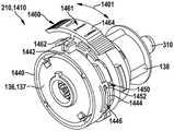
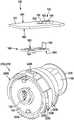
图15示出图14的档位切换单元1410,具有用于将可操纵切换环1440至少接近地固定在第一传动装置壳体件137上的固定元件1510。固定元件1510优选地按照盘的类型构造并且优选地通过夹紧连接和/或螺旋连接将切换环1440固定在第一传动装置壳体件137上。为了使可操纵切换环1440在可操纵切换环1440扭转期间轴向地移动,固定元件1510、切换环1440和/或传动装置壳体136具有至少一个楔式元件1512、1514、1516。如示出地,固定元件1510在其面向切换环1440的侧上、优选地沿着其外周缘具有至少一个楔式元件1512,如示出地,切换环1440在其内周缘上具有至少一个楔式元件1514,并且,如示出地,传动装置壳体136在其外周缘上具有至少一个楔式元件1516。楔式元件1512-1516优选地具有三角形的轮廓,然而可以具有任意的其它的轮廓,例如椭圆的轮廓。FIG. 15 shows the gear shifting unit 1410 of FIG. 14 with a securingelement 1510 for securing theactuable shifting ring 1440 at least proximally on the firsttransmission housing part 137 . The securingelement 1510 is preferably designed in the form of a disk and secures theswitching ring 1440 on the firsttransmission housing part 137 , preferably by means of a clamping connection and/or a screw connection. In order to move thesteerable switching ring 1440 axially during the torsion of thesteerable switching ring 1440 , the fixingelement 1510 , theswitching ring 1440 and/or thetransmission housing 136 have at least onewedge element 1512 , 1514 , 1516 . As shown, the fixingelement 1510 has at least onewedge element 1512 on its side facing theswitching ring 1440 , preferably along its outer circumference, as shown, theswitching ring 1440 has at least one wedge on its innercircumference Type element 1514 and, as shown,transmission housing 136 has at least onewedge element 1516 on its outer periphery. The wedge elements 1512-1516 preferably have a triangular profile, but may have any other profile, such as an elliptical profile.

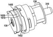
图16示出图14和图15的档位切换单元1410,为了说明切换杆1450而不包括图2的第一传动装置壳体件137。如示出地,所述切换杆具有弧形基体1620,在所述弧形基体的两个端部上分别构造有导向元件1452。此外,图16说明了具有一种替代的切换空心轮1610的、图2的传动装置130。这种切换空心轮1610优选地具有柱形的基体1612,所述柱形的基体具有用于布置切换杆1450的、槽式的槽口1640。FIG. 16 shows the gear shifting unit 1410 of FIGS. 14 and 15 without the firsttransmission housing part 137 of FIG. 2 in order to illustrate the shiftinglever 1450 . As shown, the switch lever has an arc-shapedbase body 1620 on which guideelements 1452 are each formed on both ends. Furthermore, FIG. 16 illustrates thetransmission 130 of FIG. 2 with an alternativeswitching ring gear 1610 . Such aswitching ring gear 1610 preferably has a cylindrical base body 1612 with a slot-like recess 1640 for arranging theswitching lever 1450 .

图17示出具有切换空心轮1610和切换杆1450的、图16的档位切换单元1410。在此,图17说明了切换杆1450在切换空心轮1610的槽口1640中的布置。FIG. 17 shows the gear switching unit 1410 of FIG. 16 with aswitching ring gear 1610 and aswitching lever 1450 . Here, FIG. 17 illustrates the arrangement of theswitching lever 1450 in theslot 1640 of theswitching ring gear 1610 .

图18示出在示例性的第一档位等级中或者说在第一运行模式下的、具有图14至图16的可操纵切换环1440的、替代的档位切换单元1810。类似于图2的切换环140或者图7的切换环740地,切换环1440优选地在其外周缘上具有驱动元件1820。为了进行档位切换,优选地通过调节元件180或者说从动元件186使该驱动元件1820扭转,并且在这里优选地同时在双箭头1802的方向上轴向地移动。在这里,类似于图14的切换环1440地,使切换空心轮1610轴向地移动。FIG. 18 shows an alternative gear shift unit 1810 with theactuable shift ring 1440 of FIGS. 14 to 16 in an exemplary first gear stage or in a first operating mode. Similar to switchingring 140 of FIG. 2 or switchingring 740 of FIG. 7 , switchingring 1440 preferably hasdrive elements 1820 on its outer periphery. For the gear shifting, thedrive element 1820 is preferably twisted by theactuating element 180 or theoutput element 186 and is preferably moved axially here in the direction of thedouble arrow 1802 at the same time. Here, similar to theswitching ring 1440 of FIG. 14 , theswitching ring gear 1610 is moved axially.

档位切换单元1810优选地配有图7的角度传感器710,用于切换环1440的位置探测,根据第一布置变型,所述角度传感器布置在档位切换单元1810的与从动轴310对置的背侧1801上或者说相对于切换环1440同轴线地布置。在此,角度传感器710构造用于直接地测量切换环1440的扭转。The gear switching unit 1810 is preferably equipped with anangle sensor 710 of FIG. 7 for position detection of theswitching ring 1440 , which according to a first arrangement variant is arranged on the gear switching unit 1810 opposite the drivenshaft 310 is arranged coaxially on therear side 1801 or relative to theswitching ring 1440 . In this case, theangle sensor 710 is designed to directly measure the rotation of theswitching ring 1440 .

对此替代地,取代角度传感器710能够使用图2的线性传感器155。该线性传感器优选地构造用于直接地测量切换环1440的轴向移动,所述轴向移动在切换环1440扭转时产生。Alternatively to this, thelinear sensor 155 of FIG. 2 can be used instead of theangle sensor 710 . The linear sensor is preferably configured to directly measure the axial movement of theswitching ring 1440 , which occurs when theswitching ring 1440 is twisted.

图19示出在示例性的第二档位等级中或者说在第二运行模式下的、图18的档位切换单元1810。如示出地,在此使切换环1440在轴向上朝图2的第二传动装置壳体件138的方向移动。FIG. 19 shows the gear switching unit 1810 of FIG. 18 in an exemplary second gear stage or in the second operating mode. As shown, the shiftingring 1440 is displaced here in the axial direction in the direction of the secondtransmission housing part 138 of FIG. 2 .

图20示出在示例性的第一档位等级中或者说在第一运行模式下的、图18和图19的档位切换单元1810,其中,根据第二布置变型,角度传感器710示例性地布置在切换环1440的外周缘的区域中或者说相对于切换环1440在径向上布置。如示出地,角度传感器710在此相对于调节单元180正对着对置地布置。FIG. 20 shows gear switching unit 1810 of FIGS. 18 and 19 in an exemplary first gear stage or in a first operating mode, wherein, according to a second arrangement variant,angle sensor 710 is exemplary It is arranged in the region of the outer circumference of theswitching ring 1440 or is arranged radially with respect to theswitching ring 1440 . As shown, theangle sensor 710 is here arranged opposite to theadjustment unit 180 .

图21示出在示例性的第二档位等级中或者说在第二运行模式下的、图20的档位切换单元1810。如示出地,在此使切换环1440在轴向上朝第二传动装置壳体件138的方向移动。FIG. 21 shows the gear switching unit 1810 of FIG. 20 in an exemplary second gear stage or in a second operating mode. As shown, the shiftingring 1440 is displaced here in the axial direction in the direction of the secondtransmission housing part 138 .

图22示出一种另外的替代的、具有可操纵切换环2240的档位切换单元2210。类似于以上所说明的切换环140、740和/或1440地,切换环2240优选地在其外周缘上具有驱动元件2220,所述驱动元件能够通过图2的调节单元180或者从动元件186扭转,用于档位切换。此外,切换环2240在其外周缘上具有优选地至少一个操纵滑轨、优选地两个正对着对置的操纵滑轨2246。FIG. 22 shows a further alternativegear shift unit 2210 with asteerable shift ring 2240 . Similar to the switching rings 140 , 740 and/or 1440 described above, theswitching ring 2240 preferably has on its outer periphery adrive element 2220 which can be twisted by the adjustingunit 180 or the drivenelement 186 of FIG. 2 , for gear switching. Furthermore, theswitching ring 2240 has preferably at least one actuating rail, preferably twoopposite actuating rails 2246, on its outer circumference.

此外,设置有另外的替代的切换杆2250,所述切换杆具有两个正对着对置地构造的导向元件2252,所述导向元件布置在操纵滑轨2246中,其中,切换杆2250与图2的传动装置130连接。可操纵切换环2240优选地在其外周缘上(如示出地在两个操纵滑轨2246之间)具有可与位置探测单元160连接的滑轨2248。所述滑轨构造用于在操纵可操纵切换环2240时使位置探测单元160轴向地移动。Furthermore, a furtheralternative switch lever 2250 is provided, which has twoguide elements 2252 , which are arranged in oppositely opposite directions and which are arranged in theactuating slide 2246 , wherein theswitch lever 2250 is the same as in FIG. 2 . Thetransmission 130 is connected.Steerable switching ring 2240 preferably hasslide rails 2248 on its outer periphery (as shown between two steering slide rails 2246 ) to whichposition detection unit 160 can be connected. The slide rail is configured to move theposition detection unit 160 axially when thesteerable switching ring 2240 is actuated.

图23示出图22的档位切换单元2210,其中,驱动元件2220与调节单元180连接。如示出地,可操纵切换环2240布置在其第一旋转位置上,所述第一旋转位置对应于第一档位等级或者说第一运行模式。FIG. 23 shows thegear shifting unit 2210 of FIG. 22 , wherein thedrive element 2220 is connected to theadjusting unit 180 . As shown, theactuable shift ring 2240 is arranged in its first rotational position, which corresponds to a first gear stage or a first operating mode.

图24示出在示例性的第二档位等级中或者说在第二运行模式下的、图23的档位切换单元2210。如示出地,可操纵切换环2240在此相对于图23扭转地布置。FIG. 24 shows thegear switching unit 2210 of FIG. 23 in an exemplary second gear stage or in the second operating mode. As shown, thesteerable switching ring 2240 is here twisted relative to FIG. 23 .

图25示出不包括可操纵切换环2240的、图22至图24的档位切换单元2210,并且说明了如示出地栓式的导向元件2252。导向元件2252优选地通过连接元件2512与切换杆2250连接。在此,导向元件2252和连接元件2512布置在如示出地板式的基体2514上。FIG. 25 shows thegear shift unit 2210 of FIGS. 22-24 without thesteerable shift ring 2240 and illustrates the ground-boltedguide element 2252 as shown. Theguide element 2252 is preferably connected to theswitch lever 2250 via the connectingelement 2512 . Here, theguide element 2252 and the connectingelement 2512 are arranged on a floor-like base body 2514 as shown.

连接元件2512优选地至少区段式地盖住配属于切换杆2250的弧形基体(图26中的2610)的端部。如示出地,导向元件2252和连接元件2512在图2的传动装置130的轴向方向上相互隔开间距地布置,然而导向元件2252能够在任意的其它的方向上与连接元件2512连接,例如在径向的方向上布置在连接元件2512上。The connectingelement 2512 preferably covers the end of the arcuate base body ( 2610 in FIG. 26 ) assigned to theswitching lever 2250 at least in sections. As shown, theguide element 2252 and the connectingelement 2512 are arranged at a distance from each other in the axial direction of thetransmission 130 of FIG. 2 , however theguide element 2252 can be connected to the connectingelement 2512 in any other direction, for example Arranged on the connectingelement 2512 in the radial direction.

板式的基体2514、导向元件2252和连接元件2512优选地构成导向单元2510,所述导向单元优选地布置在传动装置壳体136的接收部2520中、尤其在图2的第一传动装置壳体137的接收部中。切换杆2250优选地具有两个导向单元2510,所述两个导向单元优选地正对着对置地布置。The plate-like base body 2514 , theguide element 2252 and the connectingelement 2512 preferably form aguide unit 2510 , which is preferably arranged in thereceptacle 2520 of thetransmission housing 136 , in particular in thefirst transmission housing 137 of FIG. 2 . in the receiving department. Theswitch lever 2250 preferably has twoguide units 2510, which are preferably arranged facing each other.

图26示出不包括图2的第一传动装置壳体件137的、图25的档位切换单元2210,具有图16和图17的切换空心轮1610,该切换空心轮具有用于布置切换杆2250的槽口1640。如示出地,切换杆2250具有带有第一端部和第二端部2611、2612的弧形基体2610。所述弧形基体2610优选地按照切换箍的类型构造,然而也能够类似于图16和图17地具有矩形的横截面或者对此替代地也能够构造为线材件。在基体2610的两个端部2611、2612上优选地分别布置有导向单元2510。在此,图26说明了导向单元2510的连接元件2512在弧形基体2610的端部上的布置,其中,相应的端部2611、2612至少区段式地、优选完全地被连接元件2512盖住。FIG. 26 shows thegear shifting unit 2210 of FIG. 25 without the firsttransmission housing part 137 of FIG. 2 , with the shiftingring gear 1610 of FIGS. 16 and 17 , with the shifting ring gear for arranging the shiftinglever Notch 1640 for 2250. As shown, thetoggle lever 2250 has anarcuate base 2610 with first andsecond ends 2611, 2612. Thecurved base body 2610 is preferably designed in the manner of a switching collar, but can also have a rectangular cross-section analogously to FIGS. 16 and 17 or alternatively can also be designed as a wire part.Guide units 2510 are preferably respectively arranged on the two ends 2611 , 2612 of thebase body 2610 . 26 illustrates the arrangement of the connectingelements 2512 of theguide unit 2510 on the ends of thearcuate base body 2610 , wherein the respective ends 2611 , 2612 are covered at least in sections, preferably completely, by the connectingelements 2512 .

Claims (17)

1. Hand-held power tool (100) having a drive unit (220) with at least one drive motor (120) and a transmission (130) coupled to the drive motor (120) for driving an insertion tool, wherein the transmission (130) can be switched between at least two different gear steps, characterized in that the hand-held power tool has a communication interface (1050) which is provided for communication with a user guide unit (115, 1040) which can be actuated by a user and which is designed to receive a switching instruction from the user guide unit (115, 1040) for switching the transmission (130) between the two different gear steps in an application-specific manner, wherein the communication interface (1050) is designed to transmit a control signal to at least one operating element (115), in order to achieve that a request for initiating a switching process for switching the transmission (130) between the two different gear steps is generated by the user actuating the at least one operating element (115).
CN201680074015.XA2015-12-182016-12-07 Handheld power tool with gear switch unitActiveCN108472801B (en)

Applications Claiming Priority (3)

Application NumberPriority DateFiling DateTitle
DE102015226088.72015-12-18
DE102015226088.7ADE102015226088A1 (en)2015-12-182015-12-18 Hand tool machine with a gear shift unit
PCT/EP2016/080132WO2017102516A1 (en)2015-12-182016-12-07Hand-held power tool comprising a gearshift unit

Publications (2)

Publication NumberPublication Date
CN108472801A CN108472801A (en)2018-08-31
CN108472801Btrue CN108472801B (en)2022-06-21

Family

ID=57530670

Family Applications (1)

Application NumberTitlePriority DateFiling Date
CN201680074015.XAActiveCN108472801B (en)2015-12-182016-12-07 Handheld power tool with gear switch unit

Country Status (5)

CountryLink
US (1)US10994403B2 (en)
EP (1)EP3389944B1 (en)
CN (1)CN108472801B (en)
DE (1)DE102015226088A1 (en)
WO (1)WO2017102516A1 (en)

Families Citing this family (9)

* Cited by examiner, † Cited by third party
Publication numberPriority datePublication dateAssigneeTitle
DE102018111792A1 (en)*2017-08-292019-02-28Festool Gmbh The handheld machine tool
DE102017222006A1 (en)*2017-12-062019-06-06Robert Bosch Gmbh Hand tool with a Moduseinstelleinrichtung
DE102018208048A1 (en)*2018-05-232019-11-28Robert Bosch Gmbh Hand tool
DE102018214092A1 (en)*2018-08-212020-02-27Robert Bosch Gmbh Switching device for a hammer drill and hammer drill with a switching device
DE102019125171B4 (en)*2019-09-182023-12-21Ergobionik Gmbh Hand tool
US11602833B2 (en)*2020-06-022023-03-14Snap-On IncorporatedDirection selector mechanism for a power tool
DE102020210824A1 (en)*2020-08-272022-03-03Robert Bosch Gesellschaft mit beschränkter Haftung Hand tool with a switchable gear
DE102020212708A1 (en)2020-10-082022-04-14Robert Bosch Gesellschaft mit beschränkter Haftung hand tool
JP2022158636A (en)*2021-04-022022-10-17株式会社マキタElectric power tool and impact tool

Citations (4)

* Cited by examiner, † Cited by third party
Publication numberPriority datePublication dateAssigneeTitle
CN101479078A (en)*2006-06-272009-07-08罗伯特·博世有限公司Electric hand tool
CN102092040A (en)*2009-10-022011-06-15罗伯特.博世有限公司Handheld power tool having a shiftable mechanism
CN102785232A (en)*2011-05-192012-11-21日立工机株式会社Electric tool and communication plug for electric tool
CN104798048A (en)*2012-07-092015-07-22创科户外产品技术有限公司An interface for a power tool

Family Cites Families (28)

* Cited by examiner, † Cited by third party
Publication numberPriority datePublication dateAssigneeTitle
US5090485A (en)1987-07-301992-02-25Pomonik George MPile driving using a hydraulic actuator
US6536536B1 (en)*1999-04-292003-03-25Stephen F. GassPower tools
DE10337260A1 (en)2003-08-182005-03-10Bosch Gmbh Robert Operating module for a power tool
JP4497040B2 (en)2005-07-082010-07-07日立工機株式会社 Vibration drill
DE102006000515A1 (en)2006-12-122008-06-19Hilti Ag Electric hand tool
US9193053B2 (en)2008-09-252015-11-24Black & Decker Inc.Hybrid impact tool
US9028088B2 (en)2010-09-302015-05-12Black & Decker Inc.Lighted power tool
DE102011004495B4 (en)*2011-02-222021-11-04Robert Bosch Gmbh Hand machine tool
DE102011007648A1 (en)*2011-04-192012-10-25Robert Bosch GmbhHand tool machine has transmission that is provided for driving drive shaft and is driven by engine, where transmission is switched between two gears over semi-automatic transmission switching device in operation of hand tool machine
US20140069672A1 (en)*2011-05-202014-03-13Hitachi Koki Co., Ltd.Power Tool
JP5914840B2 (en)2012-05-112016-05-11パナソニックIpマネジメント株式会社 Automatic transmission for electric tools
WO2013187411A1 (en)2012-06-122013-12-19日立工機株式会社Power-driven device, power-driven-device system, and electric-power-tool management system
US20140107853A1 (en)*2012-06-262014-04-17Black & Decker Inc.System for enhancing power tools
JP2014023212A (en)*2012-07-132014-02-03Panasonic CorpBoost control circuit and power tool
DE102012212404B4 (en)2012-07-162017-09-28Robert Bosch Gmbh Hand machine tool device
DE102012212417B4 (en)2012-07-162017-06-08Robert Bosch Gmbh switching unit
US9256988B2 (en)*2012-09-112016-02-09Black & Decker Inc.System and method for identifying a power tool
DE102012216602A1 (en)*2012-09-182014-03-20Robert Bosch GmbhElectric power tool i.e. cordless screwdriver, has motor comprising motor shaft, and gear box formed with two gears, where tool is switched between gears when characteristic of tool reaches threshold value that is defined by user of tool
JP6033698B2 (en)2013-02-012016-11-30株式会社マキタ Electric tool
US9466198B2 (en)2013-02-222016-10-11Milwaukee Electric Tool CorporationWireless tracking of power tools and related devices
US9862263B2 (en)2013-03-012018-01-09Delbert TesarMulti-speed hub drive wheels
DE102013208895B4 (en)2013-05-142023-12-14Robert Bosch Gmbh Hand tool device
DE102013212003A1 (en)2013-06-252015-01-08Robert Bosch Gmbh Hand tool
WO2015061370A1 (en)*2013-10-212015-04-30Milwaukee Electric Tool CorporationAdapter for power tool devices
DE102014208980A1 (en)*2014-01-272015-07-30Robert Bosch Gmbh Machine tool device
DE102014209009A1 (en)*2014-01-272015-07-30Robert Bosch Gmbh Machine tool device
US20160226278A1 (en)2015-02-022016-08-04Black & Decker Inc.Power tool battery pack and system
KR102074052B1 (en)*2015-06-022020-02-05밀워키 일렉트릭 툴 코포레이션 Multi-speed power tools with electronic clutch

Patent Citations (4)

* Cited by examiner, † Cited by third party
Publication numberPriority datePublication dateAssigneeTitle
CN101479078A (en)*2006-06-272009-07-08罗伯特·博世有限公司Electric hand tool
CN102092040A (en)*2009-10-022011-06-15罗伯特.博世有限公司Handheld power tool having a shiftable mechanism
CN102785232A (en)*2011-05-192012-11-21日立工机株式会社Electric tool and communication plug for electric tool
CN104798048A (en)*2012-07-092015-07-22创科户外产品技术有限公司An interface for a power tool

Also Published As

Publication numberPublication date
EP3389944B1 (en)2020-04-22
EP3389944A1 (en)2018-10-24
US10994403B2 (en)2021-05-04
US20180370011A1 (en)2018-12-27
DE102015226088A1 (en)2017-06-22
CN108472801A (en)2018-08-31
WO2017102516A1 (en)2017-06-22

Similar Documents

PublicationPublication DateTitle
CN108472801B (en) Handheld power tool with gear switch unit
US11679484B2 (en)Hand-held power tool comprising a percussion mechanism
US11034012B2 (en)Hand-held power tool in which the direction of rotation can be set
CN104626069B (en)Hand held power machine
US11529726B2 (en)Hand-held power tool comprising a communication interface
US12226881B2 (en)System and method for configuring a power tool with an impact mechanism
AU2020200319B2 (en)Systems and methods for configuring a reciprocating saw
CN108367421B (en)Hand-held power tool with switching unit
EP3389947B1 (en)Hand-held power tool comprising a gearshift unit
CN215548419U (en) power tool
CN108367423B (en)Hand-held power tool with adjustable direction of rotation
US12440907B2 (en)Systems and methods for configuring a reciprocating saw
TWI322250B (en)

Legal Events

DateCodeTitleDescription
PB01Publication
PB01Publication
SE01Entry into force of request for substantive examination
GR01Patent grant
GR01Patent grant

[8]ページ先頭

©2009-2025 Movatter.jp