CN108464045B - User terminal, wireless base station and wireless communication method - Google Patents
User terminal, wireless base station and wireless communication methodDownload PDFInfo
- Publication number
- CN108464045B CN108464045BCN201680076148.0ACN201680076148ACN108464045BCN 108464045 BCN108464045 BCN 108464045BCN 201680076148 ACN201680076148 ACN 201680076148ACN 108464045 BCN108464045 BCN 108464045B
- Authority
- CN
- China
- Prior art keywords
- symbols
- tti
- symbol
- stti
- dmrs
- Prior art date
- Legal status (The legal status is an assumption and is not a legal conclusion. Google has not performed a legal analysis and makes no representation as to the accuracy of the status listed.)
- Active
Links
Images


Classifications
- H—ELECTRICITY
- H04—ELECTRIC COMMUNICATION TECHNIQUE
- H04L—TRANSMISSION OF DIGITAL INFORMATION, e.g. TELEGRAPHIC COMMUNICATION
- H04L27/00—Modulated-carrier systems
- H04L27/26—Systems using multi-frequency codes
- H04L27/2601—Multicarrier modulation systems
- H04L27/2602—Signal structure
- H04L27/2605—Symbol extensions, e.g. Zero Tail, Unique Word [UW]
- H04L27/2607—Cyclic extensions
- H—ELECTRICITY
- H04—ELECTRIC COMMUNICATION TECHNIQUE
- H04L—TRANSMISSION OF DIGITAL INFORMATION, e.g. TELEGRAPHIC COMMUNICATION
- H04L1/00—Arrangements for detecting or preventing errors in the information received
- H04L1/12—Arrangements for detecting or preventing errors in the information received by using return channel
- H04L1/16—Arrangements for detecting or preventing errors in the information received by using return channel in which the return channel carries supervisory signals, e.g. repetition request signals
- H04L1/18—Automatic repetition systems, e.g. Van Duuren systems
- H04L1/1812—Hybrid protocols; Hybrid automatic repeat request [HARQ]
- H—ELECTRICITY
- H04—ELECTRIC COMMUNICATION TECHNIQUE
- H04L—TRANSMISSION OF DIGITAL INFORMATION, e.g. TELEGRAPHIC COMMUNICATION
- H04L1/00—Arrangements for detecting or preventing errors in the information received
- H04L1/12—Arrangements for detecting or preventing errors in the information received by using return channel
- H04L1/16—Arrangements for detecting or preventing errors in the information received by using return channel in which the return channel carries supervisory signals, e.g. repetition request signals
- H04L1/18—Automatic repetition systems, e.g. Van Duuren systems
- H04L1/1829—Arrangements specially adapted for the receiver end
- H04L1/1861—Physical mapping arrangements
- H—ELECTRICITY
- H04—ELECTRIC COMMUNICATION TECHNIQUE
- H04L—TRANSMISSION OF DIGITAL INFORMATION, e.g. TELEGRAPHIC COMMUNICATION
- H04L5/00—Arrangements affording multiple use of the transmission path
- H04L5/003—Arrangements for allocating sub-channels of the transmission path
- H04L5/0048—Allocation of pilot signals, i.e. of signals known to the receiver
- H—ELECTRICITY
- H04—ELECTRIC COMMUNICATION TECHNIQUE
- H04L—TRANSMISSION OF DIGITAL INFORMATION, e.g. TELEGRAPHIC COMMUNICATION
- H04L5/00—Arrangements affording multiple use of the transmission path
- H04L5/003—Arrangements for allocating sub-channels of the transmission path
- H04L5/0053—Allocation of signalling, i.e. of overhead other than pilot signals
- H—ELECTRICITY
- H04—ELECTRIC COMMUNICATION TECHNIQUE
- H04W—WIRELESS COMMUNICATION NETWORKS
- H04W28/00—Network traffic management; Network resource management
- H04W28/02—Traffic management, e.g. flow control or congestion control
- H04W28/06—Optimizing the usage of the radio link, e.g. header compression, information sizing, discarding information
- H—ELECTRICITY
- H04—ELECTRIC COMMUNICATION TECHNIQUE
- H04W—WIRELESS COMMUNICATION NETWORKS
- H04W72/00—Local resource management
- H04W72/04—Wireless resource allocation
- H—ELECTRICITY
- H04—ELECTRIC COMMUNICATION TECHNIQUE
- H04W—WIRELESS COMMUNICATION NETWORKS
- H04W72/00—Local resource management
- H04W72/04—Wireless resource allocation
- H04W72/044—Wireless resource allocation based on the type of the allocated resource
- H04W72/0446—Resources in time domain, e.g. slots or frames
- H—ELECTRICITY
- H04—ELECTRIC COMMUNICATION TECHNIQUE
- H04W—WIRELESS COMMUNICATION NETWORKS
- H04W72/00—Local resource management
- H04W72/12—Wireless traffic scheduling
- H—ELECTRICITY
- H04—ELECTRIC COMMUNICATION TECHNIQUE
- H04W—WIRELESS COMMUNICATION NETWORKS
- H04W72/00—Local resource management
- H04W72/20—Control channels or signalling for resource management
Landscapes
- Engineering & Computer Science (AREA)
- Signal Processing (AREA)
- Computer Networks & Wireless Communication (AREA)
- Mobile Radio Communication Systems (AREA)
Abstract
Translated fromChinese
Description
Translated fromChinese技术领域technical field
本发明涉及下一代移动通信系统中的用户终端、无线基站及无线通信方法。The invention relates to a user terminal, a wireless base station and a wireless communication method in the next generation mobile communication system.
背景技术Background technique
在UMTS(通用移动通讯系统(Universal Mobile Telecommunications System))网络中,以进一步的高速数据速率、低延迟等为目的而长期演进(LTE:Long TermEvolution)被规范化(非专利文献1)。此外,以从LTE(也称为LTE Rel.8或9)的进一步的宽带域化及高速化为目的,LTE-A(也称为LTE-Advanced、LTE Rel.10、11或12)被规范化,还研究了LTE的后续系统(例如,也被称为FRA(未来无线接入(Future Radio Access))、5G(第五代移动通信系统(5th generation mobile communication system))、LTE Rel.13、Rel.14等)。In the UMTS (Universal Mobile Telecommunications System) network, Long Term Evolution (LTE: Long Term Evolution) is standardized for the purpose of further high-speed data rate, low delay, etc. (Non-Patent Document 1). In addition, LTE-A (also called LTE-Advanced, LTE Rel. 10, 11, or 12) is standardized for the purpose of further broadband domainization and high-speed acceleration from LTE (also called LTE Rel. 8 or 9). , also studied the successor system of LTE (for example, also known as FRA (Future Radio Access), 5G (5th generation mobile communication system (5th generation mobile communication system)), LTE Rel.13, Rel.14 etc.).
在LTE Rel.10/11中,为了实现宽带域化,引入了集中多个分量载波(CC:Component Carrier)的载波聚合(CA:Carrier Aggregation)。以LTE Rel.8的系统带域作为一个单位而构成各CC。此外,在CA中,同一无线基站(eNB:eNodeB)的多个CC被设定于用户终端(用户设备(UE:User Equipment))。In LTE Rel.10/11, in order to achieve broadband domainization, carrier aggregation (CA: Carrier Aggregation) in which multiple component carriers (CC: Component Carrier) are aggregated is introduced. Each CC is configured with the LTE Rel.8 system band as a unit. Also, in CA, a plurality of CCs of the same radio base station (eNB: eNodeB) are configured in a user terminal (user equipment (UE: User Equipment)).
另一方面,在LTE Rel.12中,还引入了不同的无线基站的多个小区组(CG:CellGroup)被设定于用户终端的双重连接(DC:Dual Connectivity)。各小区组至少由一个小区(CC)构成。由于不同的无线基站的多个CC被集中,所以DC也被称为eNB间CA(Inter-eNB CA)等。On the other hand, LTE Rel.12 also introduces dual connectivity (DC: Dual Connectivity) in which a plurality of cell groups (CG: CellGroup) of different radio base stations are set for user terminals. Each cell group consists of at least one cell (CC). Since a plurality of CCs of different radio base stations are concentrated, DC is also called inter-eNB CA (Inter-eNB CA) or the like.
此外,在LTE Rel.8-12中,引入了将下行(DL:Downlink)发送和上行(UL:Uplink)发送以不同的频带来进行的频分双工(FDD:Frequency Division Duplex)、和将DL发送和UL发送以相同的频带在时间上切换进行的时分双工(TDD:Time Division Duplex)。In addition, in LTE Rel.8-12, frequency division duplexing (FDD: Frequency Division Duplex) in which downlink (DL: Downlink) transmission and uplink (UL: Uplink) transmission are performed in different frequency bands, and Time Division Duplex (TDD: Time Division Duplex) in which DL transmission and UL transmission are time-switched in the same frequency band.
在以上那样的LTE Rel.8-12中,在无线基站和用户终端间的DL发送及UL发送中应用的传输时间间隔(TTI:Transmission Time Interval)被设定为1ms而控制。现有系统(LTE Rel.8-12)中的TTI也被称为子帧、子帧长度等。In LTE Rel.8-12 as described above, a transmission time interval (TTI: Transmission Time Interval) applied to DL transmission and UL transmission between a radio base station and a user terminal is controlled by setting it to 1 ms. TTI in existing systems (LTE Rel.8-12) is also called subframe, subframe length, etc.
现有技术文献prior art literature
非专利文献non-patent literature
非专利文献1:3GPP TS 36.300Rel.8“Evolved Universal Terrestrial RadioAccess(E-UTRA)and Evolved Universal Terrestrial Radio Access Network(E-UTRAN);Overall description;Stage 2”Non-Patent Document 1: 3GPP TS 36.300Rel.8 "Evolved Universal Terrestrial Radio Access (E-UTRA) and Evolved Universal Terrestrial Radio Access Network (E-UTRAN); Overall description;
发明内容Contents of the invention
发明要解决的课题The problem to be solved by the invention
另一方面,在Rel.13以后的LTE或5G等未来的无线通信系统中,设想进行几十GHz等高频带中的通信、或IoT(物联网(Internet of Things))、机器类型通信(MTC:MachineType Communication)、M2M(机器间通信(Machine To Machine))等数据量相对小的通信。在这样的未来的无线通信系统中,在应用现有系统(LTE Rel.8-12)中的通信方法(例如,1ms的传输时间间隔(TTI))的情况下,有不能提供充分的通信服务的顾虑。On the other hand, in future wireless communication systems such as LTE and 5G after Rel. MTC (Machine Type Communication), M2M (Machine To Machine) and other communication with relatively small amount of data. In such a future wireless communication system, in the case of applying the communication method (for example, transmission time interval (TTI) of 1 ms) in the existing system (LTE Rel. 8-12), there is a possibility that sufficient communication service cannot be provided concerns.
因此,在未来的无线通信系统中,考虑利用比1ms的TTI(以下,称为通常TTI)短的TTI(以下,称为缩短TTI)进行通信。在利用缩短TTI的情况下,怎样构成通过该缩短TTI发送的上行共享信道(物理上行链路共享信道(PUSCH:Physical UplinkShared Channel))成为问题。Therefore, in future wireless communication systems, communication using a TTI (hereinafter referred to as shortened TTI) shorter than a TTI of 1 ms (hereinafter referred to as normal TTI) is considered. When shortened TTI is used, how to configure an uplink shared channel (Physical Uplink Shared Channel (PUSCH: Physical Uplink Shared Channel)) transmitted in this shortened TTI becomes a problem.
本发明是鉴于该点而完成的,其目的之一在于提供能够使用适于缩短TTI的结构的上行共享信道进行通信的用户终端、无线基站及无线通信方法。The present invention has been made in view of this point, and one of its objects is to provide a user terminal, a radio base station, and a radio communication method capable of performing communication using an uplink shared channel with a configuration suitable for TTI shortening.
用于解决课题的手段means to solve the problem
本发明的用户终端的一方式的特征在于,具备:发送单元,在由比第一传输时间间隔(TTI)少的码元数构成的第二TTI中发送上行共享信道;以及控制单元,对所述上行共享信道的发送进行控制,所述控制单元设定所述第二TTI以使其包含发送所述第一TTI的上行共享信道的解调用参考信号的2码元中的1码元,通过所述1码元来发送所述第二TTI的上行共享信道的解调用参考信号。An aspect of the user terminal of the present invention is characterized by comprising: a transmission unit for transmitting an uplink shared channel in a second TTI consisting of symbols smaller than the first transmission time interval (TTI); and a control unit for the The transmission of the uplink shared channel is controlled, and the control unit sets the second TTI so that it includes 1 symbol among the 2 symbols of the reference signal for demodulation of the uplink shared channel that transmits the first TTI, by The 1 symbol is used to send the reference signal for demodulation of the uplink shared channel of the second TTI.
发明效果Invention effect
根据本发明,能够使用适于缩短TTI的结构的上行共享信道进行通信。According to the present invention, it is possible to perform communication using an uplink shared channel with a configuration suitable for shortening TTI.
附图说明Description of drawings
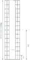
图1是表示通常TTI的结构例的图。FIG. 1 is a diagram showing a configuration example of a normal TTI.
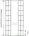
图2A及2B是表示缩短TTI的结构例的图。2A and 2B are diagrams showing configuration examples of TTI shortening.
图3A~3C是表示缩短TTI的设定例的图。3A to 3C are diagrams showing setting examples of shortened TTI.
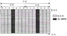
图4A~4C是表示通常TTI的PUSCH结构例的图。4A to 4C are diagrams showing PUSCH configuration examples of a normal TTI.
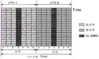
图5A及5B是表示第一方式所涉及的缩短TTI的PUSCH结构的一例的图。5A and 5B are diagrams showing an example of a TTI-shortened PUSCH structure according to the first embodiment.
图6A及6B是表示第一方式所涉及的DMRS的复用例的图。6A and 6B are diagrams showing examples of multiplexing of DMRSs according to the first embodiment.
图7A及7B是表示第一方式所涉及的DMRS的第一映射例的图。7A and 7B are diagrams showing a first mapping example of the DMRS according to the first embodiment.
图8A~8C是表示第一方式所涉及的DMRS的第二映射例的图。8A to 8C are diagrams showing a second mapping example of the DMRS according to the first aspect.
图9A及9B是第一方式所涉及的梳齿的一例的说明图。9A and 9B are explanatory diagrams of an example of comb teeth according to the first aspect.
图10A及10B是表示第一方式所涉及的缩短TTI的PUSCH结构的其他例的图。10A and 10B are diagrams showing other examples of the TTI-shortened PUSCH configuration according to the first embodiment.
图11A及11B是表示第二方式所涉及的缩短TTI的PUSCH结构的一例的图。11A and 11B are diagrams showing an example of a TTI-shortened PUSCH structure according to the second aspect.
图12是表示第二方式所涉及的UCI的第一映射例的图。FIG. 12 is a diagram showing a first mapping example of UCI according to the second aspect.
图13是表示第二方式所涉及的UCI的第二映射例的图。FIG. 13 is a diagram showing a second mapping example of UCI according to the second aspect.
图14A及14B是表示第三方式所涉及的缩短TTI的PUSCH结构的一例的图。14A and 14B are diagrams showing an example of a TTI-shortened PUSCH structure according to the third aspect.
图15是表示本实施方式所涉及的无线通信系统的概略结构的一例的图。FIG. 15 is a diagram showing an example of a schematic configuration of a wireless communication system according to this embodiment.
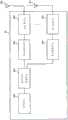
图16是表示本实施方式所涉及的无线基站的整体结构的一例的图。FIG. 16 is a diagram showing an example of an overall configuration of a radio base station according to this embodiment.
图17是表示本实施方式所涉及的无线基站的功能结构的一例的图。FIG. 17 is a diagram showing an example of a functional configuration of a radio base station according to this embodiment.
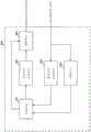
图18是表示本实施方式所涉及的用户终端的整体结构的一例的图。FIG. 18 is a diagram showing an example of an overall configuration of a user terminal according to this embodiment.
图19是表示本实施方式所涉及的用户终端的功能结构的一例的图。FIG. 19 is a diagram showing an example of a functional configuration of a user terminal according to this embodiment.
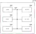
图20是表示本实施方式所涉及的无线基站及用户终端的硬件结构的一例的图。FIG. 20 is a diagram showing an example of a hardware configuration of a radio base station and a user terminal according to this embodiment.
具体实施方式Detailed ways
图1是表示现有系统(LTE Rel.8-12)中的TTI(通常TTI)的一例的图。如图1所示,通常TTI具有1ms的时间长度。通常TTI也被称为子帧,由两个时隙构成。另外,在现有系统中,通常TTI是信道编码后的1数据/分组的发送时间单位,成为调度、链路自适应等的处理单位。FIG. 1 is a diagram showing an example of a TTI (normal TTI) in a conventional system (LTE Rel. 8-12). As shown in FIG. 1 , generally a TTI has a time length of 1 ms. Usually a TTI is also called a subframe and consists of two time slots. In addition, in conventional systems, TTI is generally a transmission time unit of 1 data/packet after channel coding, and is used as a processing unit for scheduling, link adaptation, and the like.
如图1所示,在下行链路(DL)中通常循环前缀(CP)的情况下,通常TTI包含14个OFDM(正交频分复用(Orthogonal Frequency Division Multiplexing))码元(每时隙7个OFDM码元)而构成。各OFDM码元具有66.7μs的时间长度(码元长度),附加4.76μs的通常CP。由于码元长度和子载波间隔是互为倒数的关系,因此在码元长度66.7μs的情况下,子载波间隔为15kHz。As shown in Figure 1, in the case of a cyclic prefix (CP) in the downlink (DL), a typical TTI contains 14 OFDM (Orthogonal Frequency Division Multiplexing) symbols (per
此外,在上行链路(UL)中通常循环前缀(CP)的情况下,通常TTI包含14个SC-FDMA(单载波频分多址(Single Carrier Frequency Division Multiple Access))码元(每时隙7个SC-FDMA码元)而构成。各SC-FDMA码元具有66.7μs的时间长度(码元长度),附加4.76μs的通常CP。由于码元长度和子载波间隔是互为倒数的关系,因此在码元长度66.7μs的情况下,子载波间隔为15kHz。Furthermore, in the case of the usual cyclic prefix (CP) in the uplink (UL), a typical TTI consists of 14 SC-FDMA (Single Carrier Frequency Division Multiple Access) symbols (per
另外,虽未图示,但在扩展CP的情况下,通常TTI也可以包含12个OFDM码元(或12个SC-FDMA码元)而构成。在该情况下,各OFDM码元(或各SC-FDMA码元)具有66.7μs的时间长度,附加16.67μs的扩展CP。此外,也可以在UL中使用OFDM码元。以下,在不区分OFDM码元、SC-FDMA码元的情况下,称为“码元”。Also, although not shown, in the case of an extended CP, a TTI may generally include 12 OFDM symbols (or 12 SC-FDMA symbols). In this case, each OFDM symbol (or each SC-FDMA symbol) has a time length of 66.7 μs, and an extended CP of 16.67 μs is added. In addition, OFDM symbols can also be used in UL. Hereinafter, when OFDM symbols and SC-FDMA symbols are not distinguished, they are referred to as "symbols".
另一方面,在Rel.13以后的LTE或5G等未来的无线通信系统中,期望适于几十GHz等高频带的无线接口、或分组尺寸小但将延迟最小化的无线接口,以使其适于IoT(物联网)、MTC:机器类通信、M2M(机器间通信)等数据量相对小的通信。On the other hand, in future wireless communication systems such as LTE and 5G after Rel. It is suitable for communications with relatively small data volumes such as IoT (Internet of Things), MTC: Machine Type Communication, and M2M (Machine-to-Machine Communication).
在使用与通常TTI相比更短的时间长度的缩短TTI的情况下,由于对于用户终端或无线基站中的处理(例如,编码、解码等)的时间余量增加,所以能够降低处理延迟。此外,在使用缩短TTI的情况下,能够使每单位时间(例如,1ms)可容纳的用户终端数增加。因此,在未来的无线通信系统中,研究了使用与通常TTI相比更短的缩短TTI作为信道编码后的1数据/分组的发送时间单位、调度、链路自适应等的处理单位。In the case of shortened TTIs using a shorter time length than normal TTIs, processing delays can be reduced because time margins for processing (eg, encoding, decoding, etc.) in user terminals or radio base stations increase. Also, when shortened TTI is used, it is possible to increase the number of user terminals that can be accommodated per unit time (for example, 1 ms). Therefore, in future wireless communication systems, studies are being made to use shortened TTIs shorter than normal TTIs as processing units such as a transmission time unit of 1 data/packet after channel coding, scheduling, and link adaptation.
参照图2A至图2B及图3A至图3C,说明缩短TTI。图2A以及图2B是表示缩短TTI的结构例的图。如图2A及图2B所示,缩短TTI具有比1ms短的时间长度(TTI长度)。缩短TTI例如也可以是0.5ms、0.2ms、0.1ms等倍数成为1ms的TTI长度的一个或多个。或者,在通常CP的情况下通常TTI包含14个码元,因此也可以是7/14ms、4/14ms、3/14ms、1/14ms等成为1/14ms的整数倍的TTI长度的一个或多个。此外,在扩展CP的情况下通常TTI包含12个码元,因此也可以是6/12ms、4/12ms、3/12ms、1/12ms等成为1/12ms的整数倍的TTI长度的一个或多个。另外,在缩短TTI中,也与从前的LTE同样,能够通过广播信息或RRC信令等高层信令来设定(Configure)是通常CP还是扩展CP。由此,能够一边保持与1ms的通常TTI的兼容性(同步),一边引入缩短TTI。Referring to FIG. 2A to FIG. 2B and FIG. 3A to FIG. 3C , shortening of the TTI will be described. 2A and 2B are diagrams showing configuration examples of shortening TTI. As shown in FIGS. 2A and 2B , the shortened TTI has a time length (TTI length) shorter than 1 ms. For example, shortening the TTI may be one or more TTI lengths such as 0.5 ms, 0.2 ms, 0.1 ms, etc. that are multiples of 1 ms. Or, in the case of a normal CP, the TTI usually includes 14 symbols, so one or more TTI lengths such as 7/14ms, 4/14ms, 3/14ms, 1/14ms, etc. that are integer multiples of 1/14ms may be used. indivual. In addition, in the case of an extended CP, TTI usually includes 12 symbols, so it may be one or more TTI lengths such as 6/12ms, 4/12ms, 3/12ms, 1/12ms, etc., which are integer multiples of 1/12ms. indivual. Also in the shortened TTI, similar to conventional LTE, it is possible to configure (Configure) whether to use a normal CP or an extended CP by broadcasting information or higher layer signaling such as RRC signaling. This makes it possible to introduce a shortened TTI while maintaining compatibility (synchronization) with the normal TTI of 1 ms.
图2A是表示缩短TTI的第一结构例的图。如图2A所示,在第一结构例中,缩短TTI由与通常TTI同一数量的码元(在此,14个码元)构成,各码元具有与通常TTI的码元长度(例如,66.7μs)相比更短的码元长度。FIG. 2A is a diagram showing a first configuration example of shortening TTI. As shown in FIG. 2A, in the first configuration example, the shortened TTI is composed of the same number of symbols (here, 14 symbols) as the normal TTI, and each symbol has the same symbol length as the normal TTI (for example, 66.7 symbols). μs) is shorter than the symbol length.
如图2A所示,在维持通常TTI的码元数而使码元长度变短的情况下,能够沿用通常TTI的物理层信号结构(RE配置等)。此外,在维持通常TTI的码元数的情况下,在缩短TTI中也能够包含与通常TTI相同的信息量(比特量)。另一方面,由于码元时间长度与通常TTI的码元不同,因而难以将图2A所示的缩短TTI的信号和通常TTI的信号频率复用到同一系统带域(或,小区、CC)内。As shown in FIG. 2A , when the symbol length is shortened while maintaining the number of symbols of the normal TTI, the physical layer signal configuration (RE configuration, etc.) of the normal TTI can be used. Also, shortened TTIs can contain the same amount of information (amount of bits) as normal TTIs while maintaining the number of symbols in normal TTIs. On the other hand, since the symbol time length is different from that of normal TTI symbols, it is difficult to frequency-multiplex the shortened TTI signal and normal TTI signal shown in Figure 2A into the same system band (or, cell, CC) .
此外,由于码元长度和子载波间隔是互为倒数的关系,因而在如图2A所示那样使码元长度变短的情况下,子载波间隔与通常TTI的15kHz相比变得更宽。若子载波间隔变宽,则能够有效地防止用户终端的移动时的多普勒频移引起的信道间干扰、或用户终端的接收机的相位噪声引起的传输质量劣化。特别是,在几十GHz等高频带中,通过扩大子载波间隔,能够有效地防止传输质量的劣化。Also, since the symbol length and the subcarrier spacing are reciprocal to each other, when the symbol length is shortened as shown in FIG. 2A , the subcarrier spacing becomes wider than 15 kHz in normal TTI. If the subcarrier spacing is widened, it is possible to effectively prevent inter-channel interference caused by Doppler shift when the user terminal moves, or transmission quality degradation caused by phase noise in the receiver of the user terminal. In particular, in high frequency bands such as tens of GHz, the degradation of transmission quality can be effectively prevented by enlarging the subcarrier spacing.
图2B是表示缩短TTI的第二结构例的图。如图2B所示,在第二结构例中,缩短TTI由比通常TTI少的数目的码元构成,各码元具有与通常TTI相同的码元长度(例如,66.7μs)。例如,在图2B中,若设缩短TTI为通常TTI的一半的时间长度(0.5ms),则缩短TTI由通常TTI的一半的码元(在此,7个码元)构成。FIG. 2B is a diagram showing a second configuration example of shortening the TTI. As shown in FIG. 2B , in the second configuration example, the shortened TTI is composed of a smaller number of symbols than the normal TTI, and each symbol has the same symbol length (for example, 66.7 μs) as the normal TTI. For example, in FIG. 2B , if the shortened TTI is half the time length (0.5 ms) of the normal TTI, the shortened TTI consists of half the symbols of the normal TTI (here, 7 symbols).
如图2B所示,在维持码元长度而削减码元数的情况下,能够将缩短TTI中包含的信息量(比特量)与通常TTI相比更削减。因此,用户终端能够以与通常TTI相比更短的时间来进行缩短TTI中包含的信息的接收处理(例如,解调、解码等),能够缩短处理延迟。此外,能够将图2B所示的缩短TTI的信号和通常TTI的信号在同一系统带域(或小区、CC)内频率复用,能够维持与通常TTI的兼容性。As shown in FIG. 2B , when the number of symbols is reduced while maintaining the symbol length, the amount of information (bit amount) included in the shortened TTI can be reduced more than that of the normal TTI. Therefore, the user terminal can perform reception processing (for example, demodulation, decoding, etc.) of the information included in the shortened TTI in a shorter time than the normal TTI, and can shorten the processing delay. In addition, the shortened TTI signal shown in FIG. 2B and the normal TTI signal can be frequency multiplexed within the same system band (or cell, CC), and compatibility with the normal TTI can be maintained.
另外,在图2A及图2B中,示出设想了通常CP的情况(通常TTI由14个码元构成的情况)的缩短TTI的例,但缩短TTI的结构不限于图2A及2B所示。例如,在扩展CP的情况下,图2A的缩短TTI也可以由12个码元构成,图2B的缩短TTI也可以由6个码元构成。这样,缩短TTI为与通常TTI相比更短的时间长度即可,缩短TTI内的码元数、码元长度、CP长度等也可以是任意。2A and 2B show an example of shortened TTI assuming a normal CP (normal TTI is composed of 14 symbols), but the configuration of shortened TTI is not limited to that shown in FIGS. 2A and 2B . For example, in the case of an extended CP, the shortened TTI in FIG. 2A may also be composed of 12 symbols, and the shortened TTI in FIG. 2B may also be composed of 6 symbols. In this way, TTI may be shortened to a shorter time length than normal TTI, and the number of symbols, symbol length, CP length, etc. within TTI may be shortened arbitrarily.
参照图3A至图3C,说明缩短TTI的设定例。未来的无线通信系统也可以构成为能够设定通常TTI及缩短TTI这双方,以便具有与现有系统的兼容性。A setting example of shortening the TTI will be described with reference to FIGS. 3A to 3C . A future wireless communication system may be configured to be able to set both the normal TTI and the shortened TTI so as to have compatibility with existing systems.
例如,如图3A所示,通常TTI和缩短TTI也可以在同一CC(频域)内在时间上混合存在。具体而言,缩短TTI也可以被设定于同一CC的特定的子帧(或特定的无线帧等特定的时间单位)。例如,在图3A中,在同一CC内的连续的5个子帧中设定缩短TTI,在其他子帧中设定通常TTI。另外,设定缩短TTI的子帧的数目或位置不限于图3A所示。For example, as shown in FIG. 3A , normal TTIs and shortened TTIs may also exist temporally in the same CC (frequency domain). Specifically, the shortened TTI may be set in a specific subframe (or a specific time unit such as a specific radio frame) of the same CC. For example, in FIG. 3A , shortened TTIs are set in five consecutive subframes within the same CC, and normal TTIs are set in other subframes. In addition, the number or position of subframes for setting shortened TTI is not limited to that shown in FIG. 3A .
此外,如图3B所示,也可以集中通常TTI的CC和缩短TTI的CC而进行载波聚合(CA)或双重连接(DC)。具体而言,缩短TTI也可以被设定于特定的CC(更具体而言,特定的CC的DL及/或UL)。例如,在图3B中,在特定的CC的DL中设定缩短TTI,在其他CC的DL及UL中设定通常TTI。另外,设定缩短TTI的CC的数目或位置不限于图3B所示。In addition, as shown in FIG. 3B , it is also possible to perform carrier aggregation (CA) or dual connectivity (DC) by concentrating the CCs of the normal TTI and the CCs of the shortened TTI. Specifically, shortening the TTI may also be set to a specific CC (more specifically, the DL and/or UL of the specific CC). For example, in FIG. 3B , the shortened TTI is set in the DL of a specific CC, and the normal TTI is set in the DL and UL of other CCs. In addition, the number or position of the CCs for shortening the TTI is not limited to that shown in FIG. 3B .
此外,在CA的情况下,缩短TTI也可以被设定于同一无线基站的特定的CC(主(P)小区或/及副(S)小区)。另一方面,在DC的情况下,缩短TTI也可以被设定于由第一无线基站形成的主小区组(MCG)内的特定的CC(P小区或/及S小区),也可以被设定于由第二无线基站形成的副小区组(SCG)内的特定的CC(主副(PS)小区或/及S小区)。In addition, in the case of CA, the shortened TTI may be set in a specific CC (primary (P) cell or/and secondary (S) cell) of the same radio base station. On the other hand, in the case of a DC, the shortened TTI may be set to a specific CC (PCell or/and SCell) within the primary cell group (MCG) formed by the first radio base station, or may be set to Specific CCs (primary secondary (PS) cells or/and SCells) within the secondary cell group (SCG) formed by the second radio base station.
此外,如图3C所示,缩短TTI也可以被设定于DL或UL的其中一个。例如,在图3C中,在TDD系统中,对UL设定通常TTI,对DL设定缩短TTI。In addition, as shown in FIG. 3C , the shortened TTI can also be set in either DL or UL. For example, in FIG. 3C , in a TDD system, a normal TTI is set for UL and a shortened TTI is set for DL.
此外,DL或UL的特定的信道或信号也可以被分配(设定)为缩短TTI。例如,也可以是上行控制信道(物理上行链路控制信道(PUCCH:Physical Uplink Control Channel))被分配为通常TTI,上行共享信道(物理上行链路共享信道(PUSCH:Physical Uplink sharedChannel))被分配为缩短TTI。例如在该情况下,用户终端中,PUCCH的发送以通常TTI来进行,PUSCH的发送以缩短TTI来进行。In addition, a specific channel or signal of DL or UL may be assigned (set) to shorten the TTI. For example, an uplink control channel (Physical Uplink Control Channel (PUCCH: Physical Uplink Control Channel)) may be allocated as a normal TTI, and an uplink shared channel (Physical Uplink Shared Channel (PUSCH: Physical Uplink sharedChannel)) may be allocated To shorten TTI. For example, in this case, the user terminal transmits the PUCCH in the normal TTI and transmits the PUSCH in the shortened TTI.
在图3A至图3C中,用户终端基于来自无线基站的隐式(implicit)或显式(explicit)的通知,对缩短TTI进行设定(或/及检测)。以下,说明(1)隐式的通知例、以及基于(2)广播信息或RRC(无线资源控制(Radio Resource Control))信令、(3)MAC(媒体访问控制(Medium Access Control))信令、(4)PHY(物理(Physical))信令的显式的通知例。In FIG. 3A to FIG. 3C , the user terminal sets (or/and detects) the shortened TTI based on an implicit (implicit) or explicit (explicit) notification from the wireless base station. Hereinafter, (1) an example of implicit notification, and (2) broadcast information or RRC (Radio Resource Control) signaling, and (3) MAC (Medium Access Control) signaling will be described. (4) An example of explicit notification of PHY (Physical) signaling.
在(1)隐式的通知的情况下,用户终端也可以基于频带(例如,面向5G的带域、非授权带域等)、系统带宽(例如,100MHz等)、LAA(授权辅助接入(License Assisted Access))中的LBT(对话前监听(Listen Before Talk))的应用有无、所发送的数据的种类(例如,控制数据、声音等)、逻辑信道、传输块、RLC(无线链路控制(Radio Link Control))模式、C-RNTI(小区无线网络临时标识符(Cell-Radio Network Temporary Identifier))等,对缩短TTI进行设定(例如,判断进行通信的小区、信道、信号等为缩短TTI)。此外,也可以在通过被映射到通常TTI的开头1、2、3、或4码元的PDCCH及/或1ms的EPDCCH检测到发往本终端的控制信息(DCI)的情况下,将包含该PDCCH/EPDCCH的1ms判断为通常TTI,在通过采用这以外的结构的PDCCH/EPDCCH(例如被映射到通常TTI的开头1~4码元以外的PDCCH及/或小于1ms的EPDCCH)检测到发往本终端的控制信息(DCI)的情况下,将包含该PDCCH/EPDCCH的小于1ms的规定的时间区间判断为缩短TTI。在此,发往本终端的控制信息(DCI)的检测能够基于对于盲解码后的DCI的CRC的校验结果来进行。In the case of (1) implicit notification, the user terminal can also be based on the frequency band (for example, 5G-oriented band, unlicensed band, etc.), system bandwidth (for example, 100MHz, etc.), LAA (Authorized Assisted Access ( License Assisted Access) LBT (Listen Before Talk (Listen Before Talk)) application, the type of data sent (for example, control data, voice, etc.), logical channel, transport block, RLC (radio link Control (Radio Link Control)) mode, C-RNTI (Cell-Radio Network Temporary Identifier (Cell-Radio Network Temporary Identifier)), etc., set the shortened TTI (for example, determine the communication cell, channel, signal, etc. shorten the TTI). In addition, when the control information (DCI) directed to the own terminal is detected through the PDCCH mapped to the first 1, 2, 3, or 4 symbols of the normal TTI and/or the EPDCCH of 1 ms, the 1 ms of PDCCH/EPDCCH is judged to be a normal TTI, and a PDCCH/EPDCCH with a structure other than this (for example, a PDCCH other than the first 1 to 4 symbols mapped to a normal TTI and/or an EPDCCH of less than 1 ms) is detected. In the case of control information (DCI) of the own terminal, a predetermined time interval of less than 1 ms including the PDCCH/EPDCCH is judged to be shortened TTI. Here, the detection of the control information (DCI) addressed to the own terminal can be performed based on the CRC check result of the blindly decoded DCI.
在(2)广播信息或RRC信令(高层信令)的情况下,也可以基于通过广播信息或RRC信令从无线基站被通知给用户终端的设定信息,设定缩短TTI。该设定信息例如表示利用哪个CC或/及子帧作为缩短TTI,或通过缩短TTI来发送接收哪个信道或/及信号等。用户终端基于来自无线基站的设定信息,半静态(semi-static)地设定缩短TTI。另外,缩短TTI和通常TTI的模式切换也可以以RRC的重构(RRC重设定(RRC Reconfiguration))过程来进行,也可以是在P小区中通过小区内(Intra-cell)切换(HO)、在S小区中通过CC(S小区)的移除/添加(removal/addition)过程来进行。In the case of (2) broadcast information or RRC signaling (higher layer signaling), shortened TTI may be set based on configuration information notified from the radio base station to user terminals by broadcast information or RRC signaling. The setting information indicates, for example, which CC or/and subframe is used as the shortened TTI, or which channel or/and signal is transmitted and received by shortening the TTI, and the like. The user terminal sets the shortened TTI semi-statically based on the setting information from the radio base station. In addition, the mode switching between the shortened TTI and the normal TTI can also be performed through the RRC reconfiguration (RRC Reconfiguration) process, or through intra-cell handover (HO) in the PCell. 1. It is performed in the SCell through a CC (SCell) removal/addition (removal/addition) process.
在(3)MAC信令(L2(层(Layer)2)信令)的情况下,基于通过RRC信令而通知的设定信息而设定的缩短TTI也可以通过MAC信令被激活或去激活(activate或de-activate)。具体而言,用户终端基于来自无线基站的L2控制信号(例如,MAC控制元素),对缩短TTI进行激活或去激活。用户终端通过RRC等高层信令预先设定表示缩短TTI的激活期间的定时器,在通过L2控制信号激活了缩短TTI之后规定的期间没有缩短TTI的UL/DL分配的情况下,也可以将缩短TTI设为去激活。这样的缩短TTI去激活定时器也可以以通常TTI(1ms)为单位来计数,也可以以缩短TTI(例如0.25ms)为单位来计数。另外,在S小区中切换缩短TTI和通常TTI的模式的情况下,S小区可以设为被暂时去激活(de-activate),也可以视为TA(定时提前(Timing Advance))定时器期满。由此,能够设置模式切换时的通信停止期间。In the case of (3) MAC signaling (L2 (Layer 2) signaling), the shortened TTI set based on the setting information notified by RRC signaling may also be activated or deactivated by MAC signaling Activate (activate or de-activate). Specifically, the user terminal activates or deactivates the shortened TTI based on the L2 control signal (eg, MAC control element) from the radio base station. The user terminal pre-sets the timer indicating the activation period of the shortened TTI through high-level signaling such as RRC. When the UL/DL allocation of the shortened TTI is not in the specified period after the shortened TTI is activated through the L2 control signal, the shortened TTI can also be shortened. TTI is set to deactivate. Such a shortened TTI deactivation timer may also be counted in units of a normal TTI (1 ms), or may be counted in a unit of a shortened TTI (for example, 0.25 ms). In addition, when switching between the shortened TTI mode and the normal TTI mode in the SCell, the SCell may be temporarily deactivated (de-activated), or it may be considered that the TA (Timing Advance (Timing Advance)) timer has expired. . Thereby, it is possible to set a communication stop period at the time of mode switching.
在(4)PHY信令(L1(层1)信令)的情况下,基于通过RRC信令而通知的设定信息而设定的缩短TTI也可以通过PHY信令被调度。具体而言,用户终端基于所接收及检测到的L1控制信号(例如,下行控制信道(物理下行链路控制信道(PDCCH:Physical Downlink ControlChannel)或增强物理下行链路控制信道(EPDCCH:Enhanced Physical Downlink ControlChannel)、以下,称为PDCCH/EPDCCH))中包含的信息,对缩短TTI进行检测。In the case of (4) PHY signaling (L1 (layer 1) signaling), shortened TTIs configured based on configuration information notified by RRC signaling may also be scheduled by PHY signaling. Specifically, based on the received and detected L1 control signal (for example, the downlink control channel (Physical Downlink Control Channel (PDCCH: Physical Downlink ControlChannel) or enhanced physical downlink control channel (EPDCCH: Enhanced Physical Downlink ControlChannel), hereinafter referred to as PDCCH/EPDCCH)), detect shortened TTI.
例如,设为分配在通常TTI和缩短TTI中的发送或接收的控制信息(DCI)包含不同的信息元素,(4-1)用户终端在检测到包含分配在缩短TTI中的发送接收的信息元素的控制信息(DCI)的情况下,可以将包含检测出该PDCCH/EPDCCH的定时在内的规定的时间区间辨识为缩短TTI。用户终端能够在PDCCH/EPDCCH中,对分配通常TTI和缩短TTI双方的发送或接收的控制信息(DCI)进行盲解码。或者,(4-2)用户终端在检测到包含分配在缩短TTI中的发送接收的信息元素的控制信息(DCI)的情况下,也可以将包含发送/接收通过该PDCCH/EPDCCH(传输的下行控制信息(DCI:Downlink Control Information))调度的PDSCH或PUSCH的定时在内的规定的时间区间辨识为缩短TTI。或者,(4-3)用户终端在检测到包含分配在缩短TTI中的发送接收的信息元素的控制信息(DCI)的情况下,也可以将包含发送或接收对于通过该PDCCH/EPDCCH(传输的DCI)调度的PDSCH或PUSCH的重发控制信息(也称为HARQ-ACK(混合自动重发请求确认(Hybrid Automatic Repeat reQuest-Acknowledgement))、ACK/NACK、A/N等)的定时在内的规定的时间区间辨识为缩短TTI。For example, assuming that the transmitted or received control information (DCI) allocated in the normal TTI and the shortened TTI contains different information elements, (4-1) the user terminal detects that the transmitted and received information elements contained in the shortened TTI In the case of the control information (DCI) of the corresponding PDCCH/EPDCCH, a predetermined time period including the timing at which the PDCCH/EPDCCH is detected can be recognized as shortening the TTI. In the PDCCH/EPDCCH, the user terminal can blindly decode control information (DCI) that is allocated to both the normal TTI and the shortened TTI for transmission or reception. Or, (4-2) when the user terminal detects the control information (DCI) that includes the information elements for transmission and reception allocated in the shortened TTI, it may also include the transmission/reception through the PDCCH/EPDCCH (transmission downlink A predetermined time interval including the timing of the PDSCH or PUSCH scheduled by the control information (DCI: Downlink Control Information) is recognized as shortening the TTI. Alternatively, (4-3) when the user terminal detects the control information (DCI) that includes the information elements for transmission and reception allocated in the shortened TTI, it may also include the transmission or reception information for transmission through the PDCCH/EPDCCH (transmission) DCI) scheduled PDSCH or PUSCH retransmission control information (also called HARQ-ACK (Hybrid Automatic Repeat reQuest-Acknowledgment (Hybrid Automatic Repeat reQuest-Acknowledgement)), ACK/NACK, A/N, etc.) timing The specified time interval is identified as shortening the TTI.
此外,用户终端也可以基于用户终端的状态(例如,空闲(Idle)状态或连接(Connected)状态),对缩短TTI进行检测。例如,可以设为用户终端在空闲状态的情况下,将全部TTI辨识为通常TTI,且仅对1ms的通常TTI的开头1~4码元中包含的PDCCH进行盲解码。此外,用户终端在连接状态的情况下,也可以基于上述的通知例(1)-(4)的至少一个,对缩短TTI进行设定(或/及检测)。In addition, the user terminal may also detect the shortened TTI based on the state of the user terminal (for example, an idle (Idle) state or a connected (Connected) state). For example, when the user terminal is in an idle state, it may recognize all TTIs as normal TTIs, and blindly decode only PDCCHs included in the first 1 to 4 symbols of a normal TTI of 1 ms. In addition, when the user terminal is in the connected state, the shortened TTI may also be set (or/and detected) based on at least one of the above notification examples (1)-(4).
以上那样,在设定缩短TTI的情况下,怎样构成以该缩短TTI发送的PUSCH成为问题。然而,以通常TTI(子帧)发送的PUSCH如图4A至图4C所示那样构成。As described above, when the shortened TTI is set, how to configure the PUSCH transmitted in the shortened TTI becomes a problem. However, the PUSCH transmitted in a normal TTI (subframe) is configured as shown in FIGS. 4A to 4C .
如图4A-4C所示,以通常TTI发送的PUSCH的解调用参考信号(也称为DMRS:DeModulation Reference Signal、UL DMRS等)被映射到构成子帧的各时隙的规定码元。例如,在使用通常CP(各时隙由7个码元构成)的情况下,如图4A-4C所示,DMRS被映射到各时隙的索引3的码元(各时隙的中央的码元),但不限于此。在使用扩展CP(各时隙由6个码元构成)的情况下,DMRS也可以被映射到各时隙的索引2的码元。以下,将映射DMRS的规定码元称为DMRS码元。As shown in FIGS. 4A-4C , PUSCH demodulation reference signals (also referred to as DMRS: DeModulation Reference Signal, UL DMRS, etc.) transmitted in normal TTIs are mapped to predetermined symbols of each slot constituting a subframe. For example, in the case of using a normal CP (each slot consists of 7 symbols), as shown in Figures 4A-4C, the DMRS is mapped to the symbol of
在此,DMRS的序列长度与使用该DMRS解调的PUSCH的发送带宽相同。此外,DMRS的序列针对各序列长度至少定义30个序列,且分组为30个序列组。在同一小区内使用的DMRS序列属于同一序列组,在小区内使用哪个序列组(DMRS序列索引(DMRS sequence index))也可以在时隙间被变更(跳组)。序列组(DMRS序列索引)也可以基于小区ID来决定,也可以通过系统信息被通知给用户终端,也可以基于可通过用户专用的RRC信令分别被设定于PUSCH及PUCCH的虚拟小区ID来决定。Here, the sequence length of the DMRS is the same as the transmission bandwidth of the PUSCH demodulated using the DMRS. In addition, the sequence of the DMRS defines at least 30 sequences for each sequence length, and is grouped into 30 sequence groups. The DMRS sequences used in the same cell belong to the same sequence group, and which sequence group (DMRS sequence index) to use in the cell may also be changed between slots (group hopping). The sequence group (DMRS sequence index) may be determined based on the cell ID, may be notified to the user terminal through system information, or may be determined based on the virtual cell ID that can be set in the PUSCH and PUCCH respectively through user-specific RRC signaling. Decide.
此外,在同步的多个小区间,无论是哪个小区的哪个用户终端,DMRS都被映射到相同的码元(例如,图4A-4C所示的索引3的码元)。此外,被映射到同一码元的多个DMRS通过循环移位(CS:Cyclic shift)及正交码(OCC:Orthogonal Cover Code),干扰被随机化。In addition, among multiple synchronized cells, no matter which user terminal is in which cell, the DMRS is mapped to the same symbol (for example, the symbol with
在图4A中,示出在通常TTI中通过PUSCH不发送上行控制信息(UCI:上行链路控制信息(Uplink Control Information))而发送上行数据(也称为上行用户数据、UL数据)的情况下的结构例。在图4A中,对两个DMRS码元以外的各码元映射上行数据。In FIG. 4A, a case where uplink data (also referred to as uplink user data, UL data) is transmitted without transmitting uplink control information (UCI: Uplink Control Information) via PUSCH in a normal TTI structure example. In FIG. 4A , uplink data is mapped to symbols other than two DMRS symbols.
在图4B中,示出在通常TTI中通过PUSCH发送UCI和上行数据这双方的情况下的结构例。UCI也可以包含信道质量指示符(CQI:Channel Quality Indicator)、预编码矩阵指示符(PMI:Precoding Matrix Indicator)、秩指示符(RI:Rank Indicator)、或上述的HARQ-ACK的至少一个。FIG. 4B shows a configuration example in the case where both UCI and uplink data are transmitted on the PUSCH in a normal TTI. The UCI may also include a channel quality indicator (CQI: Channel Quality Indicator), a precoding matrix indicator (PMI: Precoding Matrix Indicator), a rank indicator (RI: Rank Indicator), or at least one of the aforementioned HARQ-ACK.
如图4B所示,CQI及/或PMI(以下,称为CQI/PMI)在通常TTI中,从PUSCH的发送带域(例如,1以上的物理资源块(PRB:Physical Resource Block))的一方的PRB开始,在时间方向上被映射到除了两个DMRS码元外的码元。此外,HARQ-ACK从上述发送带域的另一方的PRB开始,在时间方向上被映射到与两个DMRS码元分别相邻的码元。此外,RI在时间方向上被映射到与HARQ-ACK相邻的码元。上行数据、CQI/PMI、RI分别被编码及速率匹配,且被复用,并基于HARQ-ACK而被删截。As shown in FIG. 4B , CQI and/or PMI (hereinafter referred to as CQI/PMI) are from one of the PUSCH transmission bands (for example, 1 or more physical resource blocks (PRB: Physical Resource Block)) in a normal TTI. Starting from the PRB of , is mapped to symbols other than two DMRS symbols in the time direction. Also, HARQ-ACK is mapped to symbols adjacent to two DMRS symbols in the time direction from the PRB on the other side of the transmission band. Also, RI is mapped to symbols adjacent to HARQ-ACK in the time direction. Uplink data, CQI/PMI, and RI are coded, rate-matched, multiplexed, and punctured based on HARQ-ACK.
在图4C中,示出在通常TTI中通过PUSCH发送UCI的情况下的结构例。在图4C中,与图4B同样,CQI/PMI、HARQ-ACK、RI被映射到通常TTI内的码元。FIG. 4C shows a configuration example in the case where UCI is transmitted on the PUSCH in a normal TTI. In FIG. 4C , CQI/PMI, HARQ-ACK, and RI are mapped to symbols within a normal TTI as in FIG. 4B .
另外,在图4A-4C中,设为例示应用DFT(离散傅里叶变换(Discrete FourierTransform))之前的映射图像。实际所发送的码元也可以在频率方向上被交织而配置。设为以下所示的映射图像全部是应用DFT之前。此外,对于DMRS,不应用DFT。In addition, in FIGS. 4A-4C , it is assumed that a map image before application of DFT (Discrete Fourier Transform) is exemplified. Symbols to be actually transmitted may be interleaved and arranged in the frequency direction. Assume that the mapped images shown below are all before applying DFT. Also, for DMRS, DFT is not applied.
使用图4A-4C所示的结构,发送通常TTI中的PUSCH。但是,设想以上那样的通常TTI中的PUSCH的结构不能原样应用于由与通常TTI相比更少的码元数构成的缩短TTI(参照图2B)。另一方面,在不考虑通常TTI中的PUSCH的结构(特别是,各时隙的DMRS码元)而构成缩短TTI的PUSCH的情况下,有对于使用通常TTI发送PUSCH的用户终端(传统(legacy)UE)的干扰增大的顾虑。Using the structures shown in Figures 4A-4C, the PUSCH is transmitted in a typical TTI. However, it is assumed that the PUSCH configuration in the normal TTI as described above cannot be applied as it is to the shortened TTI (see FIG. 2B ) which consists of fewer symbols than the normal TTI. On the other hand, when configuring a PUSCH with a shortened TTI regardless of the structure of the PUSCH in the normal TTI (in particular, the DMRS symbols of each slot), there is a problem for user terminals (legacy ) UE) concerns about increased interference.
因此,本发明人们想到一边维持通常TTI的DMRS码元,一边使由与通常TTI相比更少的码元数构成的每个缩短TTI包含至少一个DMRS码元,并达到了本发明。具体而言,在本发明中,设定缩短TTI以使其包含通常TTI中的2DMRS码元的1码元,由该1码元发送接收缩短TTI的PUSCH的DMRS。Therefore, the present inventors conceived of including at least one DMRS symbol in each shortened TTI consisting of fewer symbols than the normal TTI while maintaining the DMRS symbols of the normal TTI, and arrived at the present invention. Specifically, in the present invention, the shortened TTI is set so as to include one symbol of 2 DMRS symbols in the normal TTI, and the DMRS for receiving the PUSCH of the shortened TTI is transmitted by this one symbol.
以下,参照附图详细说明本发明的一实施方式。另外,在本实施方式中,缩短TTI(第二TTI)由与通常TTI(第一TTI)相比更少的码元数构成,设为各码元具有与通常TTI相同的码元长度(参照图2B)。另外,通常TTI内包含的缩短TTI的数目例如是2、4等,但不限于此。Hereinafter, an embodiment of the present invention will be described in detail with reference to the drawings. In addition, in this embodiment, the shortened TTI (second TTI) is composed of fewer symbols than the normal TTI (first TTI), and each symbol has the same symbol length as the normal TTI (see Figure 2B). In addition, generally, the number of shortened TTIs contained in a TTI is, for example, 2, 4, etc., but not limited thereto.
此外,缩短TTI也被称为部分TTI(partial TTI)、短(short)TTI、sTTI、缩短子帧、短子帧等,通常TTI也被称为TTI、长(long)TTI、lTTI、正常TTI、通常子帧、长子帧、正常子帧、简称为子帧等。此外,以下,例示对各码元应用通常CP的情况,但不限于此。本实施方式还能够适当应用于对各码元应用扩展CP的情况。In addition, shortened TTI is also called partial TTI (partial TTI), short (short) TTI, sTTI, shortened subframe, short subframe, etc., and usually TTI is also called TTI, long (long) TTI, lTTI, normal TTI , normal subframe, long subframe, normal subframe, subframe for short, etc. In addition, the following exemplifies a case where a normal CP is applied to each symbol, but is not limited thereto. This embodiment can also be suitably applied to a case where an extended CP is applied to each symbol.
(第一方式)(first way)
在第一方式中,说明使用在缩短TTI中被分配的PUSCH发送上行数据而不发送UCI的情况下的PUSCH的结构例。In the first aspect, a PUSCH configuration example in a case where uplink data is transmitted using a PUSCH allocated in a shortened TTI and UCI is not transmitted will be described.
<维持DMRS码元的情况><The case of maintaining DMRS symbols>
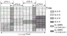
图5A及图5B是表示第一方式所涉及的缩短TTI(sTTI)中的PUSCH结构的一例的图。在图5A中,示出在每个通常TTI(子帧)包含两个sTTI的情况,在图5B中,示出每个子帧包含四个sTTI的情况。如图5A及5B所示,在包含多个sTTI的子帧中,对通常TTI的同一码元(各时隙的中央的码元)设置DMRS码元。5A and 5B are diagrams showing an example of the PUSCH configuration in the shortened TTI (sTTI) according to the first embodiment. FIG. 5A shows a case where two sTTIs are included in each normal TTI (subframe), and FIG. 5B shows a case where each subframe includes four sTTIs. As shown in FIGS. 5A and 5B , in a subframe including a plurality of sTTIs, DMRS symbols are provided for the same symbol (symbol at the center of each slot) in a normal TTI.
在图5A中,各sTTI由包含DMRS码元的7个码元构成。用户终端对第一时隙的DMRS码元(以下,称为第一DMRS码元)映射sTTI-1的DMRS,对第二时隙的DMRS码元(以下,称为第二DMRS码元)映射sTTI-2的DMRS。In FIG. 5A , each sTTI is composed of 7 symbols including DMRS symbols. The user terminal maps the DMRS of sTTI-1 to the DMRS symbol of the first time slot (hereinafter referred to as the first DMRS symbol), and maps the DMRS symbol of the second time slot (hereinafter referred to as the second DMRS symbol) DMRS for sTTI-2.
另一方面,在图5B中,各sTTI由包含在多个sTTI间共用的DMRS码元的4个码元构成。第一DMRS码元被包含于sTTI-1和STTI-2这双方,在sTTI-1和sTTI-2中共用。第二DMRS码元被包含于sTTI-3和STTI-4这双方,在sTTI-3和STTI-4中共用。On the other hand, in FIG. 5B , each sTTI is composed of four symbols including DMRS symbols shared among a plurality of sTTIs. The first DMRS symbol is included in both sTTI-1 and STTI-2, and is shared between sTTI-1 and sTTI-2. The second DMRS symbol is included in both sTTI-3 and STTI-4, and is shared between sTTI-3 and STTI-4.
在图5A及5B中,在不同的sTTI中,也可以是不同的用户终端发送PUSCH,也可以是同一用户终端发送PUSCH。此外,虽未图示,但也可以组合图5A及5B所示的结构例。例如,也可以是在子帧的第一时隙中,如图5A所示那样设定一个sTTI,在第二时隙中,如图5B所示那样设定两个sTTI,也可以设定为与此相反。In FIGS. 5A and 5B , in different sTTIs, different user terminals may transmit the PUSCH, or the same user terminal may transmit the PUSCH. In addition, although not shown, the configuration examples shown in FIGS. 5A and 5B may be combined. For example, in the first time slot of the subframe, one sTTI may be set as shown in FIG. 5A , and in the second time slot, two sTTIs may be set as shown in FIG. 5B , or it may be set as opposite of this.
如图5A所示,在单个sTTI中利用单个DMRS码元的情况下,用户终端与通常TTI的DMRS同样,能够使用由分配该sTTI的PUSCH的DCI中包含的CS/OCC指示字段(CS/OCCindicator Field)指示的循环移位索引(CS索引)及OCC来生成DMRS。As shown in FIG. 5A, in the case of using a single DMRS symbol in a single sTTI, the user terminal can use the CS/OCC indicator field (CS/OCC indicator) included in the DCI of the PUSCH allocated to the sTTI, similar to the DMRS of the normal TTI. Field) indicates the cyclic shift index (CS index) and OCC to generate DMRS.
另一方面,如图5B所示,在多个sTTI中共用单个DMRS码元的情况下,该多个sTTI的DMRS被复用到单个DMRS码元。例如,如图5B所示,在多个sTTI中共用单个DMRS码元的情况下,该多个sTTI的DMRS也可以通过循环移位及/或梳齿状的子载波配置(梳齿(Comb))而被复用。On the other hand, as shown in FIG. 5B , when a single DMRS symbol is shared among multiple sTTIs, the DMRSs of the multiple sTTIs are multiplexed into a single DMRS symbol. For example, as shown in FIG. 5B , in the case of sharing a single DMRS symbol in multiple sTTIs, the DMRSs of the multiple sTTIs can also be configured by cyclic shift and/or comb-shaped subcarriers (comb-tooth (Comb) ) to be reused.
图6A是表示共用同一DMRS码元的多个sTTI的DMRS的复用例的图。另外,在图6B中,说明在图5B的sTTI-1和sTTI-2中共用第一DMRS码元的情况下的DMRS的复用例作为一例,但在sTTI-3和sTTI-4中共用第二DMRS码元的情况下也能够同样地应用。FIG. 6A is a diagram showing an example of DMRS multiplexing of a plurality of sTTIs sharing the same DMRS symbol. In addition, in FIG. 6B, an example of DMRS multiplexing in the case of sharing the first DMRS symbol in sTTI-1 and sTTI-2 of FIG. The same applies to the case of two DMRS symbols.
在图6A中,示出使用了循环移位的复用例。各sTTI的DMRS使用不同的CS索引而生成,被映射到同一DMRS码元。例如,在图6A中,sTTI-1的DMRS使用CS索引#x来生成,另一方面,sTTI-2的DMRS使用CS索引#y来生成。另外,各sTTI的CS索引也可以由DCI内的规定字段(例如,CS/OCC指示字段、循环移位字段(Cyclic Shift Field)等)来示出。In FIG. 6A, an example of multiplexing using cyclic shift is shown. The DMRS for each sTTI is generated using a different CS index, and is mapped to the same DMRS symbol. For example, in FIG. 6A , the DMRS of sTTI-1 is generated using CS index #x, and on the other hand, the DMRS of sTTI-2 is generated using CS index #y. In addition, the CS index of each sTTI may be indicated by a predetermined field (for example, a CS/OCC indication field, a cyclic shift field (Cyclic Shift Field), etc.) in the DCI.
在图6B中,示出使用了梳齿的复用例。如图6B所示,梳齿#0及#1的子载波被交替地配置。对各sTTI的DMRS分配不同的梳齿(子载波)。例如,在图6B中,对sTTI-1的DMRS分配梳齿#0,另一方面,对sTTI-2的DMRS分配梳齿#1。各sTTI的梳齿也可以通过DCI内的规定字段(例如,CS/OCC字段等)指定(例如,若规定字段值=0则梳齿#0等),也可以根据是哪个sTTI而预先决定(例如,若sTTI1则梳齿#0等)。In FIG. 6B , an example of multiplexing using comb teeth is shown. As shown in FIG. 6B , the subcarriers of
另外,在图6A及6B中,在共用单个DMRS码元的多个sTTI中同一用户终端发送PUSCH的情况下,该用户终端也可以仅生成并发送该多个sTTI的其中一个DMRS。在该情况下,例如,在图6A中,使用CS索引#x或#y的其中一个而生成DMRS,在图6B中,对梳齿#0或#1的其中一个映射DMRS。In addition, in FIGS. 6A and 6B , when the same user terminal transmits PUSCH in a plurality of sTTIs sharing a single DMRS symbol, the user terminal may generate and transmit only one DMRS in the plurality of sTTIs. In this case, for example, in FIG. 6A , a DMRS is generated using either CS index #x or #y, and in FIG. 6B , a DMRS is mapped to either comb
此外,也可以使用图6A所示的循环移位及图6B所示的梳齿这双方,复用各sTTI的DMRS。在该情况下,在同一梳齿内通过循环移位复用多个DMRS,从而能够复用3个以上的DMRS。In addition, the DMRS for each sTTI may be multiplexed using both the cyclic shift shown in FIG. 6A and the comb teeth shown in FIG. 6B . In this case, three or more DMRSs can be multiplexed by cyclically shifting and multiplexing a plurality of DMRSs within the same comb.
参照图7A及图8A,说明共用同一DMRS码元的多个sTTI的DMRS的映射例。图7A是表示在共用同一DMRS码元的多个sTTI之间同一用户终端发送PUSCH的情况的图。另外,在图7B中,多个sTTI的PUSCH被分配给同一用户终端,所以用户终端也可以仅发送该多个sTTI的其中一个DMRS。Referring to FIG. 7A and FIG. 8A , an example of DMRS mapping of a plurality of sTTIs sharing the same DMRS symbol will be described. FIG. 7A is a diagram showing a case where the same user terminal transmits a PUSCH between a plurality of sTTIs sharing the same DMRS symbol. In addition, in FIG. 7B , PUSCHs of multiple sTTIs are allocated to the same user terminal, so the user terminal may only transmit one DMRS of the multiple sTTIs.
在图7A中,能够在共用同一DMRS码元的多个sTTI之间对不同的PRB分配PUSCH。在该情况下,DMRS也可以被映射到至少包含在该多个sTTI中被分配给PUSCH的PRB(分配PRB)的PRB。用户终端基于共用同一DMRS码元的多个sTTI中的分配PRB,决定映射(发送)DMRS的PRB(映射PRB)。In FIG. 7A , it is possible to allocate PUSCHs to different PRBs among a plurality of sTTIs that share the same DMRS symbol. In this case, the DMRS may be mapped to PRBs including at least the PRBs allocated to the PUSCH in the plurality of sTTIs (assigned PRBs). The user terminal determines PRBs to map (transmit) the DMRS based on the allocated PRBs in a plurality of sTTIs that share the same DMRS symbol (mapped PRBs).
例如,在图7A中,用户终端在第一DMRS码元中,对包含sTTI-1及sTTI-2各自的分配PRB的连续的PRB映射sTTI-1或sTTI-2的其中一个DMRS并发送。此外,用户终端在第二DMRS码元中,对包含sTTI-3及sTTI-4各自的分配PRB的连续的PRB映射sTTI-3或sTTI-4的其中一个DMRS并发送。For example, in FIG. 7A , in the first DMRS symbol, the user terminal maps one DMRS of sTTI-1 or sTTI-2 to consecutive PRBs including the allocated PRBs of sTTI-1 and sTTI-2, and transmits it. Also, in the second DMRS symbol, the user terminal maps one of the DMRSs of sTTI-3 and sTTI-4 to consecutive PRBs including the allocated PRBs of sTTI-3 and sTTI-4, and transmits it.
此外,在sTTI-2中没有对于用户终端的PUSCH的分配的情况下,该用户终端也可以在第一DMRS码元中,对sTTI-1的分配PRB映射sTTI-1的DMRS并发送。同样,在sTTI-4中没有对于用户终端的PUSCH的分配的情况下,该用户终端也可以在第二DMRS码元中,对sTTI-3的分配PRB映射sTTI-3的DMRS并发送。同样,在sTTI-1中没有对于用户终端的PUSCH的分配的情况下,该用户终端也可以在第一DMRS码元中,对sTTI-2的分配PRB映射sTTI-2的DMRS并发送。同样,在sTTI-3中没有对于用户终端的PUSCH的分配的情况下,该用户终端也可以在第二DMRS码元中,对sTTI-4的分配PRB映射sTTI-4的DMRS并发送。Also, when there is no PUSCH allocation to the user terminal in sTTI-2, the user terminal may map the DMRS of sTTI-1 to the allocated PRB of sTTI-1 in the first DMRS symbol and transmit it. Similarly, when there is no PUSCH allocation for the user terminal in sTTI-4, the user terminal may also map the DMRS of sTTI-3 to the allocated PRB of sTTI-3 in the second DMRS symbol and transmit it. Similarly, when there is no PUSCH allocation for the user terminal in sTTI-1, the user terminal may also map the DMRS of sTTI-2 to the allocated PRB of sTTI-2 in the first DMRS symbol and transmit it. Similarly, when there is no PUSCH allocation to the user terminal in sTTI-3, the user terminal may also map the DMRS of sTTI-4 to the allocated PRB of sTTI-4 in the second DMRS symbol and transmit it.
在图7A所示的情况下,基于共用同一DMRS码元的多个sTTI的分配PRB,决定该DMRS码元中的映射PRB,因此能够在该多个sTTI中灵活地分配PUSCH,并且能够进行在多个sTTI中分配的全部PRB中的信道估计。此外,能够在该DMRS码元中考虑该多个sTTI而映射DMRS。In the case shown in FIG. 7A , based on the allocated PRBs of multiple sTTIs sharing the same DMRS symbol, the mapping PRBs in the DMRS symbol are determined, so the PUSCH can be flexibly allocated in the multiple sTTIs, and it is possible to perform Channel estimation in all PRBs allocated in multiple sTTIs. Also, the DMRS can be mapped in consideration of the plurality of sTTIs in the DMRS symbol.
在图7B中,在共用同一DMRS码元的多个sTTI之间对同一PRB分配PUSCH(不能对不同的PRB分配PUSCH)。在该情况下,DMRS被映射到与该多个sTTI的其中一个的分配PRB相同的PRB。用户终端基于共用同一DMRS码元的多个sTTI之中的其中一个(例如,最初的sTTI)中的分配PRB,决定DMRS码元中的映射PRB。In FIG. 7B , PUSCHs are allocated to the same PRB among multiple sTTIs that share the same DMRS symbol (PUSCHs cannot be allocated to different PRBs). In this case, the DMRS is mapped to the same PRB as the allocated PRB of one of the plurality of sTTIs. The user terminal determines the mapped PRBs in the DMRS symbol based on the allocated PRBs in one of the plurality of sTTIs that share the same DMRS symbol (for example, the first sTTI).
例如,在图7B中,用户终端在第一DMRS码元中,对sTTI-1的分配PRB仅映射sTTI-1的DMRS并发送。在该情况下,假设在sTTI-1中被调度了PUSCH的用户终端在sTTI-2中未被分配不同的PRB。同样,用户终端在第二DMRS码元中,对sTTI-3的分配PRB仅映射sTTI-3的DMRS并发送。在该情况下,假设在sTTI-4中被调度了PUSCH的用户终端在sTTI-4中未被分配不同的PRB。For example, in FIG. 7B , in the first DMRS symbol, the user terminal only maps the DMRS of sTTI-1 to the allocated PRB of sTTI-1 and transmits it. In this case, it is assumed that a user terminal to which a PUSCH is scheduled in sTTI-1 is not allocated a different PRB in sTTI-2. Similarly, in the second DMRS symbol, the user terminal maps only the DMRS of sTTI-3 to the allocated PRB of sTTI-3 and transmits it. In this case, it is assumed that a user terminal to which a PUSCH is scheduled in sTTI-4 is not allocated a different PRB in sTTI-4.
在图7B所示的情况下,仅在共用同一DMRS码元的多个sTTI之中的最初的sTTI中,决定DMRS码元中的映射PRB及DMRS序列,因此能够开始信道估计而不用等待时间上较晚的sTTI的分配信息的解码,因此能够使处理延迟的减轻效果提高。In the case shown in FIG. 7B, the mapping PRB and DMRS sequence in the DMRS symbol are determined only in the first sTTI among a plurality of sTTIs sharing the same DMRS symbol, so channel estimation can be started without waiting time. Decoding the allocation information of the later sTTI can improve the effect of reducing the processing delay.
图8A是表示在共用同一DMRS码元的多个sTTI间之不同的用户终端发送PUSCH的情况的图。另外,在图8B中,在该多个sTTI之间对不同的用户终端分配PUSCH,所以对该多个sTTI的DMRS分别应用不同的CS索引或/及不同的梳齿。FIG. 8A is a diagram showing a case where different user terminals transmit PUSCHs between a plurality of sTTIs sharing the same DMRS symbol. In addition, in FIG. 8B , PUSCHs are allocated to different user terminals among the plurality of sTTIs, so different CS indexes or/and different comb teeth are respectively applied to the DMRSs of the plurality of sTTIs.
在图8A中,在共用同一DMRS码元的多个sTTI之间对不同的PRB分配PUSCH。在该情况下,该多个sTTI的DMRS也可以使用梳齿而被复用。具体而言,该多个sTTI的DMRS在各自的sTTI的分配PRB中,被映射到不同的梳齿。In FIG. 8A , PUSCHs are allocated to different PRBs among multiple sTTIs that share the same DMRS symbol. In this case, the DMRSs of the plurality of sTTIs may also be multiplexed using comb teeth. Specifically, the DMRSs of the multiple sTTIs are mapped to different comb teeth in the allocated PRBs of the respective sTTIs.
例如,在图8A中,设为对sTTI-1的DMRS分配梳齿#0,对sTTI-2的DMRS分配梳齿#1。在该情况下,用户终端对sTTI-1的分配PRB内的梳齿#0映射sTTI-1的DMRS。另一方面,用户终端对sTTI-2的分配PRB内的梳齿#1映射sTTI-2的DMRS。For example, in FIG. 8A ,
由此,如图8B所示,仅在sTTI-1中分配PUSCH的PRB中,仅对梳齿#0的子载波映射DMRS。另一方面,仅在sTTI-2中分配PUSCH的PRB中,仅对梳齿#1的子载波映射DMRS。此外,在sTTI-1及sTTI-2这双方中分配PUSCH的PRB中,对梳齿#0及#1的子载波映射DMRS。Therefore, as shown in FIG. 8B , only in the PRBs to which the PUSCH is allocated in sTTI-1, the DMRS is mapped only to the subcarrier of
如图8A及图8B所示,在通过梳齿对共用同一DMRS码元的多个sTTI的DMRS进行复用的情况下,能够在该多个sTTI之间对PUSCH分配不同的PRB。其结果,能够进行灵活的调度。As shown in FIGS. 8A and 8B , when DMRSs of a plurality of sTTIs sharing the same DMRS symbol are multiplexed by comb teeth, different PRBs can be allocated to the PUSCH among the plurality of sTTIs. As a result, flexible scheduling can be performed.
在图8C中,在共用同一DMRS码元的多个sTTI之间对同一PRB分配PUSCH。在该情况下,该多个sTTI的DMRS也可以使用循环移位而被复用。具体而言,该多个sTTI的DMRS使用不同的CS索引,被映射到同一PRB。用户终端基于该多个sTTI之中的其中一个(例如,最初的sTTI)中的分配PRB,决定DMRS码元中的映射PRB。In FIG. 8C , the PUSCH is allocated to the same PRB among multiple sTTIs that share the same DMRS symbol. In this case, the DMRSs of the plurality of sTTIs may also be multiplexed using cyclic shift. Specifically, the DMRSs of the multiple sTTIs use different CS indexes and are mapped to the same PRB. The user terminal determines the mapped PRB in the DMRS symbol based on the allocated PRB in one of the plurality of sTTIs (for example, the first sTTI).
例如,在图8C中,用户终端分别使用不同的CS索引而生成sTTI-1的DMRS和sTTI-2的DMRS,并映射到第一DMRS码元中的sTTI-1的分配PRB。在该情况下,假设在sTTI-1中被调度了PUSCH的用户终端在sTTI-2中未被分配不同的PRB。关于sTTI-3及sTTI-4也是同样。For example, in FIG. 8C , the user terminal uses different CS indexes to generate a DMRS of sTTI-1 and a DMRS of sTTI-2, and map them to the allocated PRBs of sTTI-1 in the first DMRS symbol. In this case, it is assumed that a user terminal to which a PUSCH is scheduled in sTTI-1 is not allocated a different PRB in sTTI-2. The same applies to sTTI-3 and sTTI-4.
如图8C所示,在假设为在共用同一DMRS码元的多个sTTI之间对同一PRB分配PUSCH的情况下,能够通过循环移位对多个sTTI的DMRS进行复用,能够使与没有将梳齿应用于DMRS的现有系统的融和性提高。此外,能够仅在该多个sTTI之中的最初的sTTI中决定DMRS的映射PRB,因此能够使处理延迟的减轻效果提高。As shown in FIG. 8C , assuming that a PUSCH is allocated to the same PRB between multiple sTTIs that share the same DMRS symbol, the DMRS of multiple sTTIs can be multiplexed by cyclic shift, and the Comb teeth are applied to the existing system of DMRS to improve compatibility. Also, since the DMRS mapping PRB can be determined only in the first sTTI among the plurality of sTTIs, the effect of reducing processing delay can be improved.
另外,在图8A及8B中,在通过梳齿对共用同一DMRS码元的多个sTTI的DMRS进行复用的情况下,也可以对各sTTI的DMRS显式地分配梳齿,也可以隐式地分配。In addition, in FIGS. 8A and 8B, in the case of multiplexing DMRSs of a plurality of sTTIs sharing the same DMRS symbol through combs, the combs may be explicitly assigned to the DMRSs of each sTTI, or may be implicitly allocated. distributed.
具体而言,也可以通过DCI(例如,分配PUSCH的UL许可)中包含的规定字段(例如,CS/OCC指示字段、循环移位字段等)的值,指示梳齿索引。例如,也可以是若CS/OCC指示字段值为0,则表示梳齿索引#0,若CS/OCC指示字段值为1,则表示梳齿索引#1。Specifically, the comb index may be indicated by the value of a predetermined field (eg, CS/OCC indication field, cyclic shift field, etc.) included in DCI (eg, UL grant for PUSCH allocation). For example, if the value of the CS/OCC indication field is 0, it indicates
或者,也可以基于发送PUSCH(调度PUSCH)的sTTI的位置或索引等,用户终端决定梳齿索引。在该情况下,关于对共用同一DMRS码元的各sTTI分配哪个梳齿,可以预先决定,也可以通过高层信令来通知。例如,在图8A中,也可以是用户终端对sTTI-1(或,sTTI-3)的DMRS决定梳齿索引#0,对sTTI-2(或,sTTI-4)的DMRS决定梳齿索引#1。Alternatively, the user terminal may determine the comb index based on the position or index of the sTTI where the PUSCH (scheduled PUSCH) is transmitted. In this case, which comb is allocated to each sTTI sharing the same DMRS symbol may be determined in advance, or may be notified through higher layer signaling. For example, in FIG. 8A , it is also possible that the user terminal determines the
此外,在对各sTTI的DMRS应用梳齿的情况下,用户终端也可以基于梳齿的数目,对PUSCH的发送功率进行控制。图9A是表示发送功率与PSD(功率谱密度(Power SpectrumDensity))的关系的图。如图9A所示,在将应用梳齿的DMRS和PUSCH的发送功率设为相同的情况下,该DMRS的PSD成为PUSCH的PSD的梳齿数(在此,2)倍。In addition, when comb teeth are applied to the DMRS of each sTTI, the user terminal may also control the transmission power of the PUSCH based on the number of comb teeth. FIG. 9A is a graph showing the relationship between transmission power and PSD (Power Spectrum Density). As shown in FIG. 9A , when the transmission power of the DMRS to which the combs are applied and the PUSCH are set to be the same, the PSD of the DMRS is twice the number of combs (here, 2) of the PSD of the PUSCH.
因此,用户终端也可以将应用梳齿的DMRS的发送功率设为1/梳齿数(在此,1/2)倍。由此,如图9B所示,DMRS的PSD变低,该DMRS的PSD和PUSCH的PSD成为等同。其结果,能够抑制DMRS引起的其他小区干扰,且易于估计上行数据的接收SINR。Therefore, the user terminal may also set the transmission power of the DMRS to which comb teeth are applied to 1/the number of comb teeth (here, 1/2) times. Accordingly, as shown in FIG. 9B , the PSD of the DMRS becomes lower, and the PSD of the DMRS becomes equal to the PSD of the PUSCH. As a result, interference from other cells caused by DMRS can be suppressed, and reception SINR of uplink data can be estimated easily.
此外,在共用同一DMRS码元的多个sTTI之间对同一PRB分配PUSCH的情况下,在图8C中,设为该多个sTTI的DMRS通过循环移位而被复用,但不限于此。该多个sTTI的DMRS也可以通过梳齿而被复用。In addition, when a PUSCH is allocated to the same PRB among a plurality of sTTIs sharing the same DMRS symbol, in FIG. 8C , it is assumed that the DMRSs of the plurality of sTTIs are multiplexed by cyclic shifting, but the present invention is not limited thereto. The DMRSs of the multiple sTTIs can also be multiplexed through comb teeth.
以上那样,在对通常TTI的各时隙的DMRS码元,映射由与该通常TTI相比更少的码元数构成的sTTI的DMRS的情况下,能够以sTTI来发送PUSCH,而不使对于以通常TTI来发送PUSCH的传统UE的干扰增大,且能够减轻处理延迟。As described above, when the DMRS of the sTTI consisting of fewer symbols than the normal TTI is mapped to the DMRS symbols of each slot of the normal TTI, it is possible to transmit the PUSCH in the sTTI without using A legacy UE that transmits a PUSCH in a normal TTI increases interference and can reduce processing delay.
<增加DMRS码元的情况><When DMRS symbols are added>
参照图10A及图10B,说明除了上述第一及第二DMRS码元外,对各sTTI设置追加的DMRS码元(以下,称为追加DMRS码元)的情况。另外,关于图10A及图10B,以与图5A及图5B的不同点为中心进行说明。Referring to FIG. 10A and FIG. 10B , a case where an additional DMRS symbol (hereinafter referred to as an additional DMRS symbol) is provided for each sTTI in addition to the first and second DMRS symbols described above will be described. 10A and 10B will be described focusing on differences from FIGS. 5A and 5B .
图10A及图10B是表示第一方式所涉及的sTTI中的PUSCH结构的其他例的图。在图10A中,示出每个子帧包含两个sTTI的情况,在图10B中,示出每个子帧包含四个sTTI的情况。如图10A及10B所示,在包含多个sTTI的子帧中,除了上述第一及第二DMRS码元外,也可以对各sTTI设置追加DMRS码元。10A and 10B are diagrams showing other examples of the PUSCH configuration in sTTI according to the first embodiment. In FIG. 10A , the case where each subframe includes two sTTIs is shown, and in FIG. 10B , the case where each subframe includes four sTTIs is shown. As shown in FIGS. 10A and 10B , in a subframe including a plurality of sTTIs, in addition to the first and second DMRS symbols described above, additional DMRS symbols may be provided for each sTTI.
例如,在图10A中,在sTTI-1中,对最初的码元(索引0)设置追加DMRS码元,在sTTI-2中,对最后的码元(索引6)设置追加DMRS码元。同样,在图10B中,在sTTI-1中,对最初的码元(索引0)设置追加DMRS码元,在sTTI-2中,对最后的码元(索引6)设置追加DMRS码元。关于sTTI-3及sTTI-4也是同样的。另外,追加DMRS码元的位置不限于图10A及10B所示。For example, in FIG. 10A , in sTTI-1, an additional DMRS symbol is set to the first symbol (index 0), and in sTTI-2, an additional DMRS symbol is set to the last symbol (index 6). Similarly, in FIG. 10B , in sTTI-1, an additional DMRS symbol is provided for the first symbol (index 0), and in sTTI-2, an additional DMRS symbol is provided for the last symbol (index 6). The same applies to sTTI-3 and sTTI-4. In addition, the positions where DMRS symbols are added are not limited to those shown in FIGS. 10A and 10B.
在图10A及10B中,上述第一及第二DMRS码元的DMRS如参照图5A-图8C说明的那样,能够使用CS索引、OCC、梳齿的至少一个而生成。由此,能够确保与以通常TTI来发送PUSCH的传统UE的正交性/随机化。In FIGS. 10A and 10B , the DMRS of the first and second DMRS symbols can be generated using at least one of CS index, OCC, and comb teeth as described with reference to FIGS. 5A to 8C . As a result, orthogonality and randomization with legacy UEs that transmit PUSCHs in normal TTIs can be ensured.
另一方面,追加DMRS码元的DMRS也可以使用与上述第一及第二DMRS码元不同的组(DMRS序列索引)的DMRS序列及/或CS索引来生成。此时,例如也可以基于小区ID或虚拟小区ID,在第一及第二DMRS码元和追加DMRS码元中改变生成DMRS序列的组(DMRS序列索引)。由此,能够在与不同的小区连接的用户终端之间将组(DMRS序列索引)的跳跃规则设为不同,因此能够增强小区间干扰的随机化。On the other hand, the DMRS to which the DMRS symbol is added may be generated using a DMRS sequence and/or a CS index of a group (DMRS sequence index) different from the above-mentioned first and second DMRS symbols. In this case, for example, based on the cell ID or virtual cell ID, the group (DMRS sequence index) that generates the DMRS sequence may be changed among the first and second DMRS symbols and the additional DMRS symbol. As a result, the hopping rules of the group (DMRS sequence index) can be set differently among user terminals connected to different cells, and thus the randomization of inter-cell interference can be enhanced.
在图10A及10B所示的情况下,与通常TTI同样,由于每sTTI包含两个DMRS码元,因此能够将以sTTI发送的PUSCH的信道估计精度设为与以通常TTI发送的PUSCH相同水平。因此,将以sTTI发送的PUSCH的信道估计精度与图5A及5B所示的结构相比,能够改善信道估计精度。In the cases shown in FIGS. 10A and 10B , as with normal TTIs, since each sTTI includes two DMRS symbols, the channel estimation accuracy of PUSCH transmitted in sTTIs can be set at the same level as that of PUSCHs transmitted in normal TTIs. Therefore, the channel estimation accuracy of the PUSCH transmitted in sTTI can be improved compared with the structure shown in FIGS. 5A and 5B .
另外,图10A及10B不过是例示,sTTI内的DMRS码元的数目不限于此。例如,在图10A及10B中,也可以通过设置2个以上的追加DMRS码元,从而每sTTI设置3个以上的DMRS码元。通过使每sTTI的DMRS码元数增加,能够进一步改善信道估计精度。In addition, FIGS. 10A and 10B are merely examples, and the number of DMRS symbols in an sTTI is not limited thereto. For example, in FIGS. 10A and 10B , three or more DMRS symbols may be provided per sTTI by providing two or more additional DMRS symbols. By increasing the number of DMRS symbols per sTTI, channel estimation accuracy can be further improved.
此外,设想对通常TTI的最后的码元,配置探测参考信号(SRS:SoundingReference Signal)而不是上行数据。因此,追加DMRS码元也可以被设定于子帧内的最后的sTTI(例如,图10A的sTTI-2、图10B的sTTI-4)的最后的码元。由此,在以通常TTI来发送PUSCH的传统UE使用对最终的码元不分配上行数据的格式(缩短格式(Shortened format))的情况下,能够避免来自该最终的码元中的sTTI的DMRS(追加DMRS)的干扰。In addition, it is assumed that a sounding reference signal (SRS: Sounding Reference Signal) instead of uplink data is placed on the last symbol of a normal TTI. Therefore, the additional DMRS symbol may be set in the last symbol of the last sTTI (for example, sTTI-2 in FIG. 10A , sTTI-4 in FIG. 10B ) in the subframe. Thus, when a legacy UE that transmits PUSCH in a normal TTI uses a format that does not allocate uplink data to the final symbol (shortened format), DMRS from the sTTI in the final symbol can be avoided. (additional DMRS) interference.
以上那样,在设置追加DMRS码元的情况下,能够一边防止对于以通常TTI来发送PUSCH的传统UE的干扰,一边提高以sTTI来发送的PUSCH的信道估计精度。As described above, when an additional DMRS symbol is provided, it is possible to improve the channel estimation accuracy of the PUSCH transmitted in the sTTI while preventing interference with legacy UEs that transmit the PUSCH in the normal TTI.
(第二方式)(second method)
在第二方式中,说明使用在sTTI中被分配的PUSCH来发送UCI及上行数据这双方的情况下的PUSCH的结构例。第二方式中的各sTTI中的DMRS的发送方法与第一方式同样,所以省略说明。在第二方式中,详细叙述UCI及上行数据对于如第一方式中说明的那样构成的sTTI内的资源元素(RE)的映射。In the second aspect, a configuration example of the PUSCH in the case where both UCI and uplink data are transmitted using the PUSCH allocated in sTTI will be described. The method of transmitting the DMRS in each sTTI in the second embodiment is the same as that in the first embodiment, and therefore description thereof will be omitted. In the second aspect, the mapping of UCI and uplink data to the resource elements (REs) in the sTTI configured as described in the first aspect will be described in detail.
另外,以下,说明维持与通常TTI同样的第一及第二DMRS码元的情况(图5A),但不限于此。第二方式中的UCI及上行数据的映射方法在除了上述第一及第二DMRS码元外还对各sTTI设置追加DMRS码元的情况(图10A)下也能够适当应用。In addition, in the following, the case of maintaining the same first and second DMRS symbols as in normal TTI ( FIG. 5A ) will be described, but the present invention is not limited thereto. The method of mapping UCI and uplink data in the second aspect can also be suitably applied to the case where an additional DMRS symbol is set for each sTTI in addition to the above-mentioned first and second DMRS symbols (FIG. 10A).
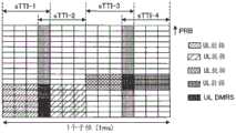
图11A及图11B是表示第二方式所涉及的sTTI中的PUSCH结构的一例的图。在图11A中,示出每个子帧包含两个sTTI的情况,在图11B中,示出每个子帧包含四个sTTI的情况。另外,在图11A及11B中,设在多个sTTI中,对同一用户终端分配PUSCH的情况、或对不同的用户终端分配PUSCH的情况的任一个中,都对该多个缩短TTI映射不同的UCI及上行数据。11A and 11B are diagrams showing an example of a PUSCH configuration in sTTI according to the second aspect. In FIG. 11A , the case where each subframe includes two sTTIs is shown, and in FIG. 11B , the case where each subframe includes four sTTIs is shown. In addition, in FIGS. 11A and 11B , it is assumed that in any of the cases where the PUSCH is allocated to the same user terminal or the PUSCH is allocated to different user terminals in a plurality of sTTIs, different sTTIs are mapped to the plurality of shortened TTIs. UCI and uplink data.
如图11A及图11B所示,在各sTTI中,UCI也可以使用与在通常TTI内映射的UCI相同的规则被映射。图12及13分别是表示图11A及11B所示的sTTI结构中的映射规则的图。另外,在图12及13中,设为资源上所附加的序号表示CQI/PMI、RI、HARQ-ACK的各自的映射顺序。As shown in FIGS. 11A and 11B , in each sTTI, UCI may be mapped using the same rules as UCI mapped in a normal TTI. 12 and 13 are diagrams showing mapping rules in the sTTI structure shown in FIGS. 11A and 11B , respectively. In addition, in FIGS. 12 and 13 , it is assumed that the sequence numbers attached to the resources indicate the respective mapping orders of CQI/PMI, RI, and HARQ-ACK.
如图12所示,在各sTTI中,CQI/PMI从PUSCH的发送带域的一方的PRB开始,在时间方向上被映射到除了DMRS码元外的码元。此外,HARQ-ACK从上述发送带域的另一方的PRB开始在时间方向上被映射到与DMRS码元相邻的2码元。此外,RI在时间方向上被映射到映射HARQ-ACK的2码元的外侧的2码元。As shown in FIG. 12 , in each sTTI, CQI/PMI is mapped to symbols other than DMRS symbols in the time direction starting from one PRB of the PUSCH transmission band. Also, HARQ-ACK is mapped to 2 symbols adjacent to the DMRS symbol in the time direction from the PRB on the other side of the transmission band. Also, RI is mapped in the time direction to 2 symbols outside of the 2 symbols to which HARQ-ACK is mapped.
此外,在图12中,上行数据被编码及速率匹配,与CQI/PMI、RI复用,基于HARQ-ACK而被删截。如图12所示,即使在应用通常TTI的同样的映射规则的情况下,各sTTI的UCI及上行数据仅被映射到各sTTI内的除DMRS码元外的码元,所映射的RE数与通常TTI相比减少。In addition, in FIG. 12, uplink data is coded and rate-matched, multiplexed with CQI/PMI, and RI, and punctured based on HARQ-ACK. As shown in Figure 12, even if the same mapping rule as the normal TTI is applied, the UCI and uplink data of each sTTI are only mapped to symbols other than DMRS symbols in each sTTI, and the number of mapped REs is the same as Usually TTI is reduced compared to.
同样,在图13所示的情况下,各sTTI的UCI及上行数据也应用通常TTI的映射规则,仅被映射到各sTTI内的除DMRS码元外的码元,所映射的RE数与通常TTI相比减少。另外,在图13中,HARQ-ACK及RI分别被映射到各sTTI内的单个码元。因此,图13中的HARQ-ACK及RI的时间方向的映射与频率方向的映射同义。Similarly, in the situation shown in Figure 13, the UCI and uplink data of each sTTI are also mapped to symbols other than DMRS symbols in each sTTI by applying the mapping rules of the normal TTI, and the number of mapped REs is the same as that of the normal TTI TTI is reduced compared to. In addition, in FIG. 13 , HARQ-ACK and RI are each mapped to a single symbol in each sTTI. Therefore, the mapping in the time direction of HARQ-ACK and RI in FIG. 13 is synonymous with the mapping in the frequency direction.
(第三方式)(third way)
在第三方式中,说明使用在sTTI中被分配的PUSCH来发送UCI而不发送上行数据的情况下的PUSCH的结构例。第三方式所涉及的PUSCH结构除了没有上行数据的映射这一点之外,与第二方式同样。In the third aspect, a PUSCH configuration example in the case where UCI is transmitted without transmitting uplink data using the PUSCH allocated in sTTI will be described. The PUSCH structure related to the third aspect is the same as the second aspect except that there is no mapping of uplink data.
图14A及图14B是表示第三方式所涉及的缩短TTI中的PUSCH结构的一例的图。图14A及图14B所示的PUSCH结构除了没有上行数据的映射这一点之外,与在第二方式(图11A及11B)中说明的PUSCH结构同样。关于图14A及图14B中的各sTTI的UCI的映射方法,与第二方式同样,所以省略说明。14A and 14B are diagrams showing an example of the PUSCH configuration in the shortened TTI according to the third aspect. The PUSCH structure shown in FIGS. 14A and 14B is the same as the PUSCH structure described in the second aspect ( FIGS. 11A and 11B ), except that there is no mapping of uplink data. The UCI mapping method for each sTTI in FIG. 14A and FIG. 14B is the same as that of the second embodiment, and thus description thereof will be omitted.
另外,在图14A中,说明维持与通常TTI同样的第一及第二DMRS码元的情况(图5A),但不限于此。第三方式中的UCI的映射方法在除了上述第一及第二DMRS码元外还对各sTTI设置追加DMRS码元的情况(图10A)下也能够适当应用。In addition, in FIG. 14A, the case where the same first and second DMRS symbols are maintained as in the normal TTI ( FIG. 5A ) is described, but the present invention is not limited thereto. The UCI mapping method in the third aspect can also be suitably applied to the case where an additional DMRS symbol is set for each sTTI in addition to the above-mentioned first and second DMRS symbols (FIG. 10A).
(其他)(other)
如在第二及第三方式中说明的那样,在以sTTI的PUSCH来发送UCI的情况下(UCIon PUSCH),也可以通过与以通常TTI的PUSCH发送的UCI不同的规则,进行有效载荷限制。As described in the second and third aspects, when UCI is transmitted on the sTTI PUSCH (UCIon PUSCH), payload limitation may be performed by a different rule from UCI transmitted on the normal TTI PUSCH.
例如,在第二及第三方式中,在HARQ-ACK的有效载荷超过规定的阈值的情况、或HARQ-ACK的有效载荷相对于PUSCH的RE数的比率(即,编码率)超过规定的阈值的情况下,也可以应用空间捆绑。另外,该规定的阈值也可以通过高层信令被通知给用户终端。For example, in the second and third forms, when the payload of HARQ-ACK exceeds a predetermined threshold, or the ratio of the payload of HARQ-ACK to the number of REs of PUSCH (that is, the coding rate) exceeds a predetermined threshold In the case of , spatial bundling can also be applied. In addition, the specified threshold may also be notified to the user terminal through high-layer signaling.
此外,在第二及第三方式中,在CQI/PMI的有效载荷超过规定的阈值的情况、或CQI/PMI的有效载荷相对于PUSCH的RE数的比率(即,编码率)超过规定的阈值的情况下,优先级低的CQI/PMI也可以被丢弃(也可以是发送被中止)。另外,CQI/PMI的优先级也可以与现有系统中的优先级相同。Also, in the second and third forms, when the payload of CQI/PMI exceeds a predetermined threshold, or the ratio of the payload of CQI/PMI to the number of REs of PUSCH (that is, the coding rate) exceeds a predetermined threshold In the case of , the CQI/PMI with low priority may also be discarded (or the transmission may be suspended). In addition, the priority of the CQI/PMI may also be the same as that in the existing system.
例如,在第二及第三方式中,在RI的有效载荷超过规定的阈值的情况、或RI的有效载荷相对于PUSCH的RE数的比率(即,编码率)超过规定的阈值的情况,也可以结合多个小区的RI。另外,对哪些多个小区的RI进行结合也可以通过高层信令被通知给用户终端。此外,作为多个小区的RI的结合方法,考虑(1)使用多个小区的RI的平均、(2)使用多个小区的RI的最大值、(3)使用多个小区的RI的最小值等。For example, in the second and third forms, when the payload of RI exceeds a predetermined threshold, or when the ratio of the payload of RI to the number of REs of PUSCH (that is, the coding rate) exceeds a predetermined threshold, the RIs of multiple cells can be combined. In addition, which multiple cells' RIs are to be combined may also be notified to the user terminal through high-level signaling. Also, as a method of combining RIs of multiple cells, (1) using the average of RIs of multiple cells, (2) using the maximum value of RIs of multiple cells, and (3) using the minimum value of RIs of multiple cells wait.
或者,关于以sTTI来发送的PUSCH中包含的数据、CQI/PMI、RI、HARQ-ACK,也可以将它们的连结比特串视为一个码字,进行联合编码。由此,能够节省对数据、UCI分别单独地追加的CRC比特,所以能够削减开销。在数据(传输块)较大,且被分割为多个码块而分别进行编码的情况下,UCI也可以设为在最初、最后、或特定的顺序的码块中进行联合编码。此时,也可以设为数据和UCI的连结比特串以数据、HARQ-ACK、RI、CQI/PMI的顺序构成。在比特串的尺寸相对于无线资源量过大的情况下,使CQI/PMI的全部或一部分缺失(丢弃),但由于在丢弃前后对码字比特串的数据、HARQ-ACK、RI的位置不会带来影响,所以能够简化编码处理。此外,作为在进行了联合编码时将编码比特映射到无线资源的顺序,能够应用与数据相同的顺序。Alternatively, data, CQI/PMI, RI, and HARQ-ACK included in the PUSCH transmitted in sTTI may be jointly encoded by treating their concatenated bit strings as one codeword. This saves CRC bits to be added separately to data and UCI, so that overhead can be reduced. When the data (transport block) is large and is divided into a plurality of code blocks and coded separately, UCI may be configured to perform joint coding on the first, last, or specific order of code blocks. In this case, the concatenated bit sequence of data and UCI may be configured in the order of data, HARQ-ACK, RI, and CQI/PMI. When the size of the bit string is too large relative to the amount of radio resources, all or part of the CQI/PMI is deleted (discarded). will have an effect, so the encoding process can be simplified. In addition, as the order of mapping coded bits to radio resources when joint coding is performed, the same order as that of data can be applied.
(无线通信系统)(wireless communication system)
以下,说明本发明的一实施方式所涉及的无线通信系统的结构。在该无线通信系统中,应用上述各方式所涉及的无线通信方法。另外,上述各方式所涉及的无线通信方法也可以分别单独应用,也可以组合应用。Hereinafter, a configuration of a wireless communication system according to an embodiment of the present invention will be described. In this wireless communication system, the wireless communication methods according to the above-mentioned aspects are applied. In addition, the wireless communication methods related to the above-mentioned modes may be applied individually or in combination.
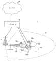
图15是表示本实施方式所涉及的无线通信系统的概略结构的一例的图。在无线通信系统1中,能够应用将以LTE系统的系统带宽(例如,20MHz)为1个单位的多个基本频率块(分量载波)设为一体的载波聚合(CA)及/或双重连接(DC)。另外,无线通信系统1也可以被称为超3G、LTE-A(LTE-Advanced)、IMT-Advanced、4G、5G、FRA(未来无线接入)等。FIG. 15 is a diagram showing an example of a schematic configuration of a wireless communication system according to this embodiment. In the
图15所示的无线通信系统1具备形成宏小区C1的无线基站11、和被配置在宏小区C1内且形成比宏小区C1窄的小型小区C2的无线基站12a~12c。此外,在宏小区C1及各小型小区C2中,配置有用户终端20。The
用户终端20能够与无线基站11及无线基站12这双方连接。设想用户终端20通过CA或DC同时使用利用不同的频率的宏小区C1和小型小区C2。此外,用户终端20能够使用多个小区(CC)(例如,6个以上的CC)应用CA或DC。The
用户终端20和无线基站11之间能够以相对低的频带(例如,2GHz)使用带宽窄的载波(被称为现有载波、传统载波(Legacy carrier)等)进行通信。另一方面,用户终端20和无线基站12之间也可以以相对高的频带(例如,3.5GHz、5GHz等)使用带宽宽的载波,也可以使用和与无线基站11之间相同的载波。另外,各无线基站利用的频带的结构不限于此。Communication between the
无线基站11和无线基站12之间(或两个无线基站12间)能够设为有线连接(例如,遵照CPRI(通用公共无线接口(Common Public Radio Interface))的光纤、X2接口等)或无线连接的结构。Between the
无线基站11及各无线基站12分别与上位站装置30连接,且经由上位站装置30与核心网络40连接。另外,在上位站装置30中,例如包含接入网关装置、无线网络控制器(RNC)、移动性管理实体(MME)等,但并非限定于此。此外,各无线基站12也可以经由无线基站11与上位站装置30连接。The
另外,无线基站11是具有相对宽的覆盖范围的无线基站,也可以被称为宏基站、汇聚节点、eNB(eNodeB)、发送接收点等。此外,无线基站12是具有局部的覆盖范围的无线基站,也可以被称为小型基站、微基站、微微基站、毫微微基站、HeNB(Home eNodeB)、RRH(远程无线头(Remote Radio Head))、发送接收点等。以下,在不区分无线基站11及12的情况下,统称为无线基站10。In addition, the
各用户终端20是支持LTE、LTE-A等各种通信方式的终端,不仅包含移动通信终端,也可以包含固定通信终端。Each
在无线通信系统1中,作为无线接入方式,对下行链路应用OFDMA(正交频分多址),对上行链路应用SC-FDMA(单载波-频分多址)。OFDMA是将频带分割为多个窄的频带(子载波),对各子载波映射数据而进行通信的多载波传输方式。SC-FDMA是将系统带宽按每个终端分割为由一个或连续的资源块构成的带域,通过多个终端使用相互不同的带域,从而降低终端间的干扰的单载波传输方式。另外,上行及下行的无线接入方式不限于它们的组合,也可以在上行链路中使用OFDMA。In the
在无线通信系统1中,作为下行链路的信道,使用在各用户终端20中共享的下行共享信道(物理下行链路共享信道(PDSCH:Physical Downlink Shared Channel))、广播信道(物理广播信道(PBCH:Physical Broadcast Channel))、下行L1/L2控制信道等。通过PDSCH,传输用户数据或高层控制信息、SIB(系统信息块(System Information Block))等。此外,通过PBCH,传输MIB(主信息块(Master Information Block))。In the
下行L1/L2控制信道包含下行控制信道(PDCCH(物理下行链路控制信道)、EPDCCH(增强物理下行链路控制信道))、PCFICH(物理控制格式指示信道(Physical ControlFormat Indicator Channel))、PHICH(物理混合ARQ指示信道(Physical Hybrid-ARQIndicator Channel))等。通过PDCCH,传输包含PDSCH及PUSCH的调度信息的下行控制信息(下行链路控制信息(DCI:Downlink Control Information))等。通过PCFICH,传输用于PDCCH的OFDM码元数。通过PHICH,传输对于PUSCH的HARQ的送达确认信息(ACK/NACK)。EPDCCH与PDSCH(下行共享数据信道)频分复用,与PDCCH同样地被用于DCI等的传输。Downlink L1/L2 control channels include downlink control channels (PDCCH (Physical Downlink Control Channel), EPDCCH (Enhanced Physical Downlink Control Channel)), PCFICH (Physical Control Format Indicator Channel (Physical ControlFormat Indicator Channel)), PHICH ( Physical Hybrid-ARQ Indicator Channel (Physical Hybrid-ARQ Indicator Channel)) and the like. The PDCCH transmits downlink control information (downlink control information (DCI: Downlink Control Information)) including scheduling information of the PDSCH and the PUSCH, and the like. Through PCFICH, the number of OFDM symbols used for PDCCH is transmitted. The HARQ acknowledgment information (ACK/NACK) for the PUSCH is transmitted through the PHICH. The EPDCCH is frequency-division multiplexed with the PDSCH (Downlink Shared Data Channel), and is used for transmission of DCI and the like similarly to the PDCCH.
在无线通信系统1中,作为上行链路的信道,使用在各用户终端20中共享的上行共享信道(物理上行链路共享信道(PUSCH:Physical Uplink Shared Channel))、上行控制信道(物理上行链路控制信道(PUCCH:Physical Uplink Control Channel))、随机接入信道(物理随机接入信道(PRACH:Physical Random Access Channel))等。通过PUSCH,传输用户数据、高层控制信息。包含送达确认信息(ACK/NACK)或无线质量信息(CQI)等的至少一个的上行控制信息(上行链路控制信息(UCI:Uplink Control Information))通过PUSCH或PUCCH被传输。通过PRACH,传输用于与小区建立连接的随机接入前导码。In the
<无线基站><Wireless Base Station>
图16是表示本实施方式所涉及的无线基站的整体结构的一例的图。无线基站10具备多个发送接收天线101、放大器单元102、发送接收单元103、基带信号处理单元104、呼叫处理单元105、传输路径接口106。另外,发送接收天线101、放大器单元102、发送接收单元103也可以构成为分别包含一个以上。FIG. 16 is a diagram showing an example of an overall configuration of a radio base station according to this embodiment. The
通过下行链路从无线基站10发送至用户终端20的用户数据,从上位站装置30经由传输路径接口106输入至基带信号处理单元104。User data transmitted from the
在基带信号处理单元104中,关于用户数据,进行PDCP(分组数据汇聚协议(PacketData Convergence Protocol))层的处理、用户数据的分割/结合、RLC(无线链路控制)重发控制等RLC层的发送处理、MAC(媒体访问控制)重发控制(例如,HARQ(混合自动重发请求)的发送处理)、调度、传输格式选择、信道编码、快速傅里叶反变换(IFFT:Inverse FastFourier Transform)处理、预编码处理等发送处理而转发至发送接收单元103。此外,关于下行控制信号,也进行信道编码或快速傅里叶反变换等发送处理,并转发至发送接收单元103。In the baseband
发送接收单元103将从基带信号处理单元104按每个天线进行预编码而输出的基带信号变换为无线频带而发送。由发送接收单元103频率变换后的无线频率信号通过放大器单元102被放大,从发送接收天线101发送。Transmitting and receiving
能够由基于本发明所涉及的技术领域中的共同认知而说明的发射机/接收机、发送接收电路或发送接收装置构成。另外,发送接收单元103也可以作为一体的发送接收单元而构成,也可以由发送单元及接收单元构成。It can be constituted by a transmitter/receiver, a transmission/reception circuit, or a transmission/reception device explained based on common knowledge in the technical field to which the present invention relates. In addition, the transmitting and receiving
另一方面,关于上行信号,由发送接收天线101接收到的无线频率信号被放大器单元102放大。发送接收单元103接收由放大器单元102放大后的上行信号。发送接收单元103将接收信号频率变换为基带信号,并输出至基带信号处理单元104。On the other hand, regarding the uplink signal, the radio frequency signal received by the transmitting and receiving
此外,发送接收单元103在由与通常TTI(第一TTI)相比更少的码元数构成的缩短TTI(第二TTI)中接收PUSCH。在该PUSCH中,可以包含上行数据(第一方式),也可以包含上行数据及UCI这双方(第二方式),也可以包含UCI(第三方式)。Also, transmitting/receiving
此外,发送接收单元103在设定缩短TTI以使其包含接收通常TTI的PUSCH的DMRS(解调用参考信号)的2码元中的1码元的情况下,由该1码元接收该缩短TTI的PUSCH的DMRS。此外,发送接收单元103在对缩短TTI设定追加DMRS码元的情况下,也可以由追加DMRS码元接收该缩短TTI的DMRS。In addition, when the transmission/
在基带信号处理单元104中,对所输入的上行信号中包含的用户数据,进行快速傅里叶变换(FFT:Fast Fourier Transform)处理、离散傅里叶反变换(IDFT:InverseDiscrete Fourier Transform)处理、纠错解码、MAC重发控制的接收处理、RLC层及PDCP层的接收处理,经由传输路径接口106而转发至上位站装置30。呼叫处理单元105进行通信信道的设定或释放等呼叫处理、或无线基站10的状态管理、或无线资源的管理。In the baseband
传输路径接口106经由规定的接口,与上位站装置30对信号进行发送接收。此外,传输路径接口106也可以经由基站间接口(例如,遵照CPRI(通用公共无线接口)的光纤、X2接口)与相邻无线基站10对信号进行发送接收(回程信令)。The
图17是表示本实施方式所涉及的无线基站的功能结构的一例的图。另外,图17主要示出本实施方式中的特征部分的功能块,设无线基站10还具有无线通信所需的其他功能块。如图17所示,基带信号处理单元104具备控制单元301、发送信号生成单元302、映射单元303、接收信号处理单元304。FIG. 17 is a diagram showing an example of a functional configuration of a radio base station according to this embodiment. In addition, FIG. 17 mainly shows the functional blocks of the characteristic parts in this embodiment, and it is assumed that the
控制单元301实施无线基站10整体的控制。控制单元301例如对由发送信号生成单元302进行的下行信号的生成、或由映射单元303进行的信号的映射、由接收信号处理单元304进行的信号的接收处理进行控制。The
具体而言,控制单元301基于从用户终端20报告的信道状态信息(CSI),进行下行(DL)信号的发送控制(例如,调制方式、编码率、资源分配(调度)等的控制)。Specifically, the
此外,控制单元301对被用于下行信号的接收及/或上行信号的发送的传输时间间隔(TTI)进行控制。控制单元301设定1ms的通常TTI或/及比通常TTI短的缩短TTI。关于缩短TTI的结构例及设定例,如参照图2A-图2B及图3A-图3C说明的那样。控制单元301也可以对用户终端20,通过(1)隐式的通知、或基于(2)RRC信令、(3)MAC信令、(4)PHY信令的至少一个的显式的通知,指示缩短TTI的设定。In addition, the
具体而言,控制单元301设定各缩短TTI(第二TTI),以使其包含发送通常TTI(第一TTI)的PUSCH的DMRS的2码元(DMRS码元)中的一个码元(图5A-图5B、图10A-图10B、图11A-图11B及图14A-图14B)。控制单元301对接收信号处理单元304进行控制,以便基于由该1DMRS码元(或,该1DMRS码元及追加DMRS码元)接收到的DMRS,对缩短TTI中的PUSCH进行解调。Specifically, the
控制单元301能够由基于本发明所涉及的技术领域中的共同认知而说明的控制器、控制电路或控制装置构成。The
发送信号生成单元302基于来自控制单元301的指示,生成下行信号(包含下行数据信号、下行控制信号),输出至映射单元303。具体而言,发送信号生成单元302生成基于上述的高层信令的通知信息(控制信息)或包含用户数据的下行数据信号(PDSCH),输出至映射单元303。此外,发送信号生成单元302生成包含上述的DCI的下行控制信号(PDCCH/EPDCCH),输出至映射单元303。此外,发送信号生成单元302生成CRS、CSI-RS等下行参考信号,输出至映射单元303。The transmission
发送信号生成单元302能够设为基于本发明所涉及的技术领域中的共同认知而说明的信号生成器、信号生成电路或信号生成装置。The transmission
映射单元303基于来自控制单元301的指示,将由发送信号生成单元302生成的下行信号映射到规定的无线资源,输出至发送接收单元103。映射单元303能够设为基于本发明所涉及的技术领域中的共同认知而说明的映射器、映射电路或映射装置。
接收信号处理单元304对从用户终端20发送的上行信号,进行接收处理(例如,解映射、解调、解码等)。具体而言,接收信号处理单元304使用由缩短TTI中包含的上述1DMRS码元(或,上述1DMRS码元及追加DMRS码元)接收到的DMRS,对缩短TTI中的PUSCH进行解调。处理结果被输出至控制单元301。The received
接收信号处理单元304能够由基于本发明所涉及的技术领域中的共同认知而说明的信号处理器、信号处理电路或信号处理装置、以及测量器、测量电路或测量装置构成。The received
<用户终端><User terminal>
图18是表示本实施方式所涉及的用户终端的整体结构的一例的图。用户终端20具有用于MIMO传输的多个发送接收天线201、放大器单元202、发送接收单元203、基带信号处理单元204、应用单元205。FIG. 18 is a diagram showing an example of an overall configuration of a user terminal according to this embodiment. The
由多个发送接收天线201接收到的无线频率信号分别被放大器单元202放大。各发送接收单元203接收由放大器单元202放大后的下行信号。发送接收单元203将接收信号频率变换为基带信号,输出至基带信号处理单元204。The radio frequency signals received by the plurality of transmitting and receiving
基带信号处理单元204对所输入的基带信号,进行FFT处理、或纠错解码、重发控制的接收处理等。下行数据(用户数据)转发至应用单元205。应用单元205进行有关与物理层或MAC层相比更上位的层的处理等。此外,下行链路的数据之中广播信息也被转发至应用单元205。The baseband
另一方面,关于上行数据,从应用单元205被输入至基带信号处理单元204。在基带信号处理单元204中,进行重发控制的发送处理(例如,HARQ的发送处理)、或信道编码、速率匹配、删截、离散傅里叶变换(DFT:Discrete Fourier Transform)处理、IFFT处理等而转发至各发送接收单元203。关于UCI,也进行信道编码、速率匹配、删截、DFT处理、IFFT处理等而转发至各发送接收单元203。On the other hand, the uplink data is input from the
发送接收单元203将从基带信号处理单元204输出的基带信号变换为无线频带而发送。由发送接收单元203频率变换后的无线频率信号通过放大器单元202被放大,从发送接收天线201发送。Transmitting and receiving
此外,发送接收单元203在由与通常TTI(第一TTI)相比更少的码元数构成的缩短TTI(第二TTI)中发送PUSCH。在该PUSCH中,可以包含上行数据(第一方式),也可以包含上行数据及UCI这双方(第二方式),也可以包含UCI(第三方式)。Also, transmitting/receiving
此外,发送接收单元203在设定缩短TTI以使其包含接收通常TTI的PUSCH的DMRS(解调用参考信号)的2DMRS码元的1DMRS码元的情况下,由该1DMRS码元发送该缩短TTI的PUSCH的DMRS。此外,发送接收单元203在对缩短TTI设定追加DMRS码元的情况下,也可以由追加DMRS码元发送该缩短TTI的DMRS。In addition, when the transmission/
发送接收单元203能够设为基于本发明所涉及的技术领域中的共同认知而说明的发射机/接收机、发送接收电路或发送接收装置。此外,发送接收单元203也可以作为一体的发送接收单元而构成,也可以由发送单元及接收单元构成。The transmitting and receiving
图19是表示本实施方式所涉及的用户终端的功能结构的一例的图。另外,在图19中,主要示出本实施方式中的特征部分的功能块,设用户终端20还具有无线通信所需的其他功能块。如图19所示,用户终端20具有的基带信号处理单元204具备控制单元401、发送信号生成单元402、映射单元403、接收信号处理单元404、测量单元405。FIG. 19 is a diagram showing an example of a functional configuration of a user terminal according to this embodiment. In addition, in FIG. 19 , functional blocks that are characteristic parts in this embodiment are mainly shown, and it is assumed that the
控制单元401实施用户终端20整体的控制。控制单元401例如对由发送信号生成单元402进行的信号的生成、或由映射单元403进行的信号的映射、由接收信号处理单元404进行的信号的接收处理进行控制。The
此外,控制单元401对被用于下行(DL)信号的接收及/或上行(UL)信号的发送的传输时间间隔(TTI)进行控制。控制单元301设定1ms的通常TTI或/及比通常TTI短的缩短TTI。关于缩短TTI的结构例及设定例,如参照图2A-图2B及图3A-图3C说明的那样。控制单元401也可以根据来自无线基站10的(1)隐式的通知、或基于(2)RRC信令、(3)MAC信令、(4)PHY信令的至少一个的显式的通知,对缩短TTI进行设定(检测)。In addition, the
具体而言,控制单元401设定缩短TTI(第二TTI),以使其包含发送通常TTI(第一TTI)中的PUSCH的DMRS的2DMRS码元中的一个码元(图5A-图5B、图10A-图10B、图11A-图11B及图14A-图14B)。此外,控制单元401对发送信号生成单元402进行控制以便由该1DMRS码元(或,该1DMRS码元及追加DMRS码元)发送该缩短TTI中的DMRS。Specifically, the
例如,在多个缩短TTI包含上述1DMRS码元的情况下,控制单元401将该多个缩短TTI的解调用参考信号复用到该1DMRS码元内而发送。即,控制单元401将该多个缩短的TTI之中的某缩短TTI的DMRS和其他缩短TTI的DMRS复用到上述1DMRS码元而发送。在该复用中,能够利用循环移位及/或梳齿。For example, when a plurality of shortened TTIs includes the aforementioned 1 DMRS symbol,
在该多个缩短TTI中同一用户终端20发送PUSCH的情况下,且能够对该PUSCH分配不同的资源块的情况下(图7A),控制单元401基于在该多个缩短TTI中分别被分配的PRB来决定发送DMRS的PRB。控制单元401也可以对发送信号生成单元402进行控制,以使其使用所决定的PRB发送该多个缩短TTI的其中一个(例如,最早的缩短TTI)的DMRS。In the case where the
此外,在该多个缩短TTI中同一用户终端20发送PUSCH的情况下,且不能对该PUSCH分配不同的资源块的情况下(图7B),控制单元401将在该多个缩短TTI的其中一个(例如,最早的缩短TTI)中被分配的PRB决定为发送DMRS的PRB。控制单元401也可以对发送信号生成单元402进行控制,以使其使用所决定的PRB发送该多个缩短TTI的其中一个(例如,最早的缩短TTI)的DMRS。In addition, in the case that the
此外,在该多个缩短TTI中不同的用户终端20发送PUSCH的情况下,且能够对该PUSCH分配不同的资源块的情况下(图8A),控制单元401也可以使用梳齿将该多个缩短TTI的DMRS复用到上述1DMRS码元。具体而言,控制单元401对发送信号生成单元402进行控制以使其使用与其他用户终端20不同的梳齿索引发送缩短TTI的DMRS。另外,梳齿索引也可以由DCI的规定字段来指示,也可以根据sTTI而预先决定。In addition, when
此外,在该多个缩短TTI中不同的用户终端20发送PUSCH的情况下,且不能对该PUSCH分配不同的资源块的情况下(图8B),控制单元401也可以使用循环移位将该多个缩短TTI的DMRS复用到上述1DMRS码元。具体而言,控制单元401对发送信号生成单元402进行控制以使其使用与其他用户终端20不同的CS索引发送缩短TTI的DMRS。另外,也可以由DCI的规定字段(例如,CS/OCC字段)来指示使用哪个CS索引。In addition, when
控制单元401能够由基于本发明所涉及的技术领域中的共同认知而说明的控制器、控制电路或控制装置构成。The
发送信号生成单元402基于来自控制单元401的指示,生成(例如,编码、速率匹配、删截、调制等)上行信号(包含上行数据信号、上行控制信号),输出至映射单元403。例如,发送信号生成单元402生成包括上行数据的PUSCH、包括上行数据和UCI(HARQ-ACK、CQI/PMI、RI的至少一个)的PUSCH、包括UCI的PUSCH。The transmission
具体而言,发送信号生成单元402在上述多个缩短TTI中同一用户终端20发送PUSCH的情况下(图7A及7B),使用在其中一个缩短TTI(例如,最早的缩短TTI)中由DCI指示的CS索引及/或OCC,生成DMRS。Specifically, when the
此外,发送信号生成单元402在上述多个缩短TTI中不同的用户终端20发送PUSCH的情况下(图8A及8B),使用在用户终端20发送的缩短TTI中由DCI指示的CS索引及/或OCC,生成DMRS。In addition, when
此外,发送信号生成单元402也可以使用与由上述1DMRS码元发送的DMRS不同的组(DMRS序列索引)的DMRS序列而生成由上述追加DMRS码元发送的DMRS。Also, transmission
发送信号生成单元402能够设为基于本发明所涉及的技术领域中的共同认知而说明的信号生成器、信号生成电路或信号生成装置。The transmission
映射单元403基于来自控制单元401的指示,将由发送信号生成单元402生成的UL信号(上行控制信号及/或上行数据信号)映射到无线资源,输出至发送接收单元203。
具体而言,映射单元403在上述1DMRS码元(或,包含追加DMRS码元)中,对由控制单元401决定的PRB,映射由发送信号生成单元402生成的DMRS。映射单元403能够设为基于本发明所涉及的技术领域中的共同认知而说明的映射器、映射电路或映射装置。Specifically,
接收信号处理单元404对下行信号(包含下行控制信号、下行数据信号),进行接收处理(例如,解映射、解调、解码等)。接收信号处理单元404将从无线基站10接收到的信息输出至控制单元401。接收信号处理单元404例如将广播信息、系统信息、基于RRC信令等高层信令的控制信息、DCI等输出至控制单元401。The received
接收信号处理单元404能够由基于本发明所涉及的技术领域中的共同认知而说明的信号处理器、信号处理电路或信号处理装置构成。此外,接收信号处理单元404能够构成本发明所涉及的接收单元。The received
测量单元405基于来自无线基站10的参考信号(例如,CSI-RS),对信道状态进行测量,将测量结果输出至控制单元401。另外,信道状态的测量也可以按每个CC来进行。The
测量单元405能够由基于本发明所涉及的技术领域中的共同认知而说明的信号处理器、信号处理电路或信号处理装置、以及测量器、测量电路或测量装置构成。The measuring
(硬件结构)(hardware structure)
另外,用于上述实施方式的说明的框图示出了功能单位的块。这些功能块(结构单元)通过硬件及/或软件的任意的组合来实现。此外,各功能块的实现手段没有被特别限定。即,各功能块也可以通过在物理上结合的一个装置来实现,也可以将在物理上分离的两个以上的装置以有线或无线的方式连接,并通过这多个装置来实现。In addition, the block diagrams used in the description of the above-mentioned embodiments show blocks as functional units. These functional blocks (structural units) are realized by any combination of hardware and/or software. In addition, the realization means of each functional block is not specifically limited. That is, each functional block may be realized by a single device that is physically connected, or two or more physically separated devices may be connected in a wired or wireless manner and realized by these multiple devices.
例如,本实施方式中的无线基站、用户终端等也可以作为进行本发明的无线通信方法的处理的计算机来发挥作用。图20是表示本实施方式所涉及的无线基站及用户终端的硬件结构的一例的图。上述的无线基站10及用户终端20也可以作为在物理上包含处理器1001、存储器1002、储存器1003、通信装置1004、输入装置1005、输出装置1006、总线1007等的计算机装置来构成。For example, the wireless base station, the user terminal, etc. in this embodiment may also function as a computer that performs the processing of the wireless communication method of the present invention. FIG. 20 is a diagram showing an example of a hardware configuration of a radio base station and a user terminal according to this embodiment. The
另外,在以下的说明中,“装置”这样的语言能够替换为电路、设备、单元等。无线基站10及用户终端20的硬件结构也可以构成为包含一个或多个图示的各装置,也可以构成为不包含一部分装置。In addition, in the following description, the language of "device" can be replaced with a circuit, a device, a unit, or the like. The hardware configurations of the
无线基站10及用户终端20中的各功能通过在处理器1001、存储器1002等硬件上读入规定的软件(程序),从而处理器1001进行运算,对由通信装置1004进行的通信、或存储器1002及储存器1003中的数据的读出及/或写入进行控制从而实现。Each function in the
处理器1001例如使操作系统操作而对计算机整体进行控制。处理器1001也可以由包含与外围装置的接口、控制装置、运算装置、寄存器等的中央处理装置(中央处理单元(CPU:Central Processing Unit))构成。例如,上述的基带信号处理单元104(204)、呼叫处理单元105等也可以由处理器1001实现。The
此外,处理器1001将程序(程序代码)、软件模块或数据从储存器1003及/或通信装置1004读出至存储器1002,按照它们而执行各种处理。作为程序,使用使计算机执行在上述的实施方式中说明的操作的至少一部分的程序。例如,用户终端20的控制单元401也可以通过被储存至存储器1002且由处理器1001操作的控制程序来实现,关于其他功能块也可以同样地实现。Furthermore, the
存储器1002是计算机可读取的记录介质,例如,也可以由ROM(只读存储器(ReadOnly Memory))、EPROM(可擦除可编程(Erasable Programmable)ROM)、RAM(随机存取存储器(Random Access Memory))等的至少一个构成。存储器1002也可以被称为寄存器、高速缓存、主存储器(主存储装置)等。存储器1002能够保存为了实施本实施方式所涉及的无线通信方法而可执行的程序(程序代码)、软件模块等。The
储存器1003是计算机可读取的记录介质,例如也可以由CD-ROM(紧凑盘(CompactDisc)ROM)等光盘、硬盘驱动、软盘、光磁盘、闪速存储器等的至少一个构成。储存器1003也可以被称为辅助存储装置。The
通信装置1004是用于经由有线及/或无线网络进行计算机间的通信的硬件(发送接收设备),例如也称为网络设备、网络控制器、网卡、通信模块等。例如,上述的发送接收天线101(201)、放大器单元102(202)、发送接收单元103(203)、传输路径接口106等也可以由通信装置1004实现。The
输入装置1005是受理来自外部的输入的输入设备(例如,键盘、鼠标等)。输出装置1006是实施向外部的输出的输出设备(例如,显示器、扬声器等)。另外,输入装置1005及输出装置1006也可以是成为一体的结构(例如,触摸面板)。The
此外,处理器1001或存储器1002等各装置通过用于进行信息通信的总线1007来连接。总线1007可以由单个总线构成,也可以在装置间由不同的总线来构成。In addition, various devices such as the
此外,无线基站10及用户终端20也可以包含微处理器、ASIC(专用集成电路(Application Specific Integrated Circuit))、PLD(可编程逻辑器件(ProgrammableLogic Device))、FPGA(现场可编程门阵列(Field Programmable Gate Array))等硬件而构成,也可以通过该硬件,实现各功能块的一部分或全部。例如,处理器1001也可以被安装于这些硬件的至少一个。In addition, the
另外,关于在本说明书中说明的用语及/或本说明书的理解所需的用语,也可以置换为具有同一或类似的含义的用语。例如,信道及/或码元也可以是信号(信令)。此外,信号也可以是消息。此外,分量载波(CC:Component Carrier)也可以被称为小区、频率载波、载波频率等。In addition, the terms described in this specification and/or terms necessary for the understanding of this specification may be replaced with terms having the same or similar meanings. For example, a channel and/or a symbol may also be a signal (signaling). Furthermore, a signal can also be a message. In addition, a component carrier (CC: Component Carrier) may also be called a cell, a frequency carrier, a carrier frequency, and the like.
此外,无线帧也可以在时域中由一个或多个期间(帧)构成。构成无线帧的该一个或多个各期间(帧)也可以被称为子帧。进而,子帧也可以在时域中由一个或多个时隙构成。进而,时隙也可以在时域中由一个或多个码元(OFDM码元、SC-FDMA码元等)构成。In addition, a radio frame may be composed of one or more periods (frames) in the time domain. The one or more periods (frames) constituting a radio frame may also be referred to as subframes. Furthermore, a subframe may also consist of one or more slots in the time domain. Furthermore, a slot may be composed of one or more symbols (OFDM symbols, SC-FDMA symbols, etc.) in the time domain.
无线帧、子帧、时隙及码元都表示传输信号时的时间单位。无线帧、子帧、时隙及码元也可以使用与它们对应的别的称呼。例如,1子帧也可以被称为发送时间间隔(TTI:Transmission Time Interval),多个连续的子帧也可以被称为TTI,1时隙也可以被称为TTI。也就是说,子帧或TTI也可以是现有的LTE中的子帧(1ms),也可以是比1ms短的期间(例如,1-13码元),也可以是比1ms长的期间。Radio frames, subframes, slots, and symbols all represent time units when transmitting signals. Radio frames, subframes, slots, and symbols may use other names corresponding to them. For example, one subframe may also be called a transmission time interval (TTI: Transmission Time Interval), multiple consecutive subframes may also be called a TTI, and one time slot may also be called a TTI. That is, the subframe or TTI may be a subframe (1 ms) in conventional LTE, may be shorter than 1 ms (for example, 1-13 symbols), or may be longer than 1 ms.
在此,TTI例如是指无线通信中的调度的最小时间单位。例如,在LTE系统中,无线基站对各用户终端进行以TTI单位来分配无线资源(在各用户终端中能够使用的频带宽或发送功率等)的调度。另外,TTI的定义不限于此。Here, TTI refers to, for example, the minimum time unit for scheduling in wireless communication. For example, in the LTE system, a radio base station performs scheduling to allocate radio resources (frequency bandwidth, transmission power, etc. that can be used by each user terminal) in units of TTIs to each user terminal. In addition, the definition of TTI is not limited to this.
资源块(RB:Resource Block)是时域及频域的资源分配单位,也可以在频域中包含一个或多个连续的副载波(子载波(subcarrier))。此外,RB也可以在时域中包含一个或多个码元,也可以是1时隙、1子帧或1TTI的长度。1TTI、1子帧也可以分别由一个或多个资源块构成。另外,RB也可以被称为物理资源块(PRB:Physical RB)、PRB对、RB对等。A resource block (RB: Resource Block) is a resource allocation unit in the time domain and frequency domain, and may include one or more consecutive subcarriers (subcarriers) in the frequency domain. In addition, an RB may also include one or more symbols in the time domain, and may also have a length of 1 slot, 1 subframe, or 1 TTI. 1 TTI and 1 subframe may each be composed of one or more resource blocks. In addition, an RB may also be called a physical resource block (PRB: Physical RB), a PRB pair, or an RB pair.
此外,资源块也可以由一个或多个资源元素(RE:Resource Element)构成。例如,1RE也可以是1子载波及1码元的无线资源区域。In addition, a resource block may also be composed of one or more resource elements (RE: Resource Element). For example, 1 RE may be a radio resource region of 1 subcarrier and 1 symbol.
另外,上述的无线帧、子帧、时隙及码元等的构造不过是例示。例如,无线帧中包含的子帧的数目、子帧中包含的时隙的数目、时隙中包含的码元及RB的数目、RB中包含的子载波的数目、以及TTI内的码元数、码元长度、循环前缀(CP:Cyclic Prefix)长度等的结构能够进行各种变更。In addition, the structures of the above-mentioned radio frame, subframe, slot, symbol, etc. are merely examples. For example, the number of subframes included in a radio frame, the number of slots included in a subframe, the number of symbols and RBs included in a slot, the number of subcarriers included in an RB, and the number of symbols in a TTI , symbol length, cyclic prefix (CP:Cyclic Prefix) length, etc., can be changed in various ways.
此外,在本说明书中说明的信息、参数等也可以以绝对值来表示,也可以以相对于规定的值的相对值来表示,也可以以对应的别的信息来表示。例如,无线资源也可以以规定的索引来指示。In addition, information, parameters, and the like described in this specification may be expressed as absolute values, may be expressed as relative values to predetermined values, or may be expressed as other corresponding information. For example, radio resources may be indicated by predetermined indexes.
在本说明书中说明的信息、信号等也可以使用各种不同的技术的其中一个来表示。例如,在上述的说明整体中可提及的数据、命令、指令、信息、信号、比特、码元、码片等也可以通过电压、电流、电磁波、磁场或磁性粒子、光场或光子、或它们的任意组合来表示。Information, signals, etc. described in this specification may also be represented using any of a variety of different technologies. For example, data, commands, instructions, information, signals, bits, symbols, chips, etc. that may be mentioned throughout the above description may also be transmitted by voltage, current, electromagnetic waves, magnetic fields or magnetic particles, light fields or photons, or any combination of them.
此外,软件、命令、信息等也可以经由传输介质而发送接收。例如,在使用有线技术(同轴线缆、光纤线缆、双绞线及数字订户线路(DSL)等)及/或无线技术(红外线、微波等)从网站、服务器、或其他远程源发送软件的情况下,这些有线技术及/或无线技术被包含于传输介质的定义内。In addition, software, commands, information, etc. may also be sent and received via transmission media. For example, when sending software from a website, server, or other remote source using wire technology (coaxial cable, fiber optic cable, twisted pair, digital subscriber line (DSL), etc.) and/or wireless technology (infrared, microwave, etc.) Where applicable, these wired and/or wireless technologies are included in the definition of transmission medium.
此外,本说明书中的无线基站也可以替换为用户终端。例如,关于将无线基站及用户终端间的通信置换为多个用户终端间的通信(D2D:Device-to-Device)的结构,也可以应用本发明的各方式/实施方式。在该情况下,也可以设为用户终端20具有上述的无线基站10具有的功能的结构。此外,“上行”或“下行”等的语言也可以被替换为“侧(side)”。例如,上行信道也可以被替换为侧信道。In addition, the radio base station in this specification may be replaced with a user terminal. For example, each mode/embodiment of the present invention can also be applied to a configuration in which communication between a radio base station and a user terminal is replaced with communication between a plurality of user terminals (D2D: Device-to-Device). In this case, the
同样,本说明书中的用户终端也可以替换为无线基站。在该情况下,也可以设为无线基站10具有上述的用户终端20具有的功能的结构。Likewise, the user terminal in this specification can also be replaced by a wireless base station. In this case, the
在本说明书中说明的各方式/实施方式也可以单独使用,也可以组合使用,也可以伴随执行而切换使用。此外,规定的信息的通知(例如,“是X”的通知)不限于显式地进行,也可以隐式地(例如,通过不进行该规定的信息的通知)进行。The various modes/embodiments described in this specification may be used alone, may be used in combination, or may be switched and used as they are executed. In addition, notification of predetermined information (for example, notification of "Yes X") is not limited to being performed explicitly, but may be performed implicitly (for example, by not notifying the predetermined information).
信息的通知不限于在本说明书中说明的方式/实施方式,也可以以其他方法来进行。例如,信息的通知也可以通过物理层信令(例如,DCI(下行链路控制信息(DownlinkControl Information))、UCI(上行链路控制信息))、高层信令(例如,RRC(无线资源控制)信令、广播信息(MIB(主信息块)、SIB(系统信息块)等)、MAC(媒体访问控制)信令)、其他信号或它们的组合来实施。此外,RRC信令也可以被称为RRC消息,例如也可以是RRC连接设置(RRCConnectionSetup)消息、RRC连接重构(RRCConnectionReconfiguration)消息等。此外,MAC信令例如也可以由MAC控制元素(MAC CE(Control Element))来通知。Notification of information is not limited to the modes/embodiments described in this specification, and may be performed by other methods. For example, the notification of information may also be through physical layer signaling (for example, DCI (Downlink Control Information (Downlink Control Information)), UCI (Uplink Control Information)), higher layer signaling (for example, RRC (Radio Resource Control) Signaling, broadcast information (MIB (Master Information Block), SIB (System Information Block), etc.), MAC (Media Access Control) signaling), other signals or their combination. In addition, the RRC signaling may also be called an RRC message, such as an RRC Connection Setup (RRCConnectionSetup) message, an RRC Connection Reconfiguration (RRCConnectionReconfiguration) message, and the like. In addition, the MAC signaling may be notified by, for example, a MAC control element (MAC CE (Control Element)).
在本说明书中说明的各方式/实施方式也可以被应用于LTE(长期演进(Long TermEvolution))、LTE-A(LTE-Advanced)、LTE-B(LTE-Beyond)、超3G、IMT-Advanced、4G(第四代移动通信系统)、5G(第五代移动通信系统)、FRA(未来无线接入)、New-RAT(无线接入技术(Radio Access Technology))、CDMA2000、UMB(超移动宽带(Ultra Mobile Broadband))、IEEE 802.11(Wi-Fi(注册商标))、IEEE 802.16(WiMAX(注册商标))、IEEE 802.20、UWB(超宽带(Ultra-WideBand))、蓝牙(Bluetooth)(注册商标)、利用其他恰当的系统的系统及/或基于它们而扩展的下一代系统。The modes/embodiments described in this specification can also be applied to LTE (Long Term Evolution), LTE-A (LTE-Advanced), LTE-B (LTE-Beyond), Super 3G, and IMT-Advanced , 4G (Fourth Generation Mobile Communication System), 5G (Fifth Generation Mobile Communication System), FRA (Future Radio Access), New-RAT (Radio Access Technology), CDMA2000, UMB (Ultra Mobile Broadband (Ultra Mobile Broadband)), IEEE 802.11 (Wi-Fi (registered trademark)), IEEE 802.16 (WiMAX (registered trademark)), IEEE 802.20, UWB (Ultra-WideBand (Ultra-WideBand)), Bluetooth (Bluetooth) (registered trademark), systems that utilize other appropriate systems and/or next-generation systems that expand upon them.
在本说明书中说明的各方式/实施方式的处理过程、时序、流程图等只要没有矛盾,也可以调换顺序。例如,关于在本说明书中说明的方法,以例示的顺序提示各种步骤的元素,不限定于所提示的特定的顺序。The processing procedures, sequences, flowcharts, etc. of the respective modes/embodiments described in this specification may be switched in order unless there is a contradiction. For example, with regard to the method described in this specification, elements of various steps are presented in the order of illustration, and are not limited to the specific order presented.
以上,详细说明了本发明,但对本领域技术人员来说,本发明并非限定于在本说明书中说明的实施方式是显而易见的。例如,上述的各实施方式也可以单独使用,也可以组合使用。本发明能够作为修正及变更方式来实施而不会脱离由权利要求书的记载决定的本发明的宗旨及范围。从而,本说明书的记载以例示说明为目的,对本发明并非具有任何限制性的含义。As mentioned above, although this invention was demonstrated in detail, it is clear to those skilled in the art that this invention is not limited to embodiment demonstrated in this specification. For example, each of the above-mentioned embodiments may be used alone or in combination. The present invention can be implemented as corrected and modified forms without departing from the gist and scope of the present invention determined by the claims. Therefore, the description in this specification is for the purpose of illustration and description, and does not have any restrictive meaning to the present invention.
本申请基于2015年12月25日申请的特愿2015-255029。其内容全部包含于此。This application is based on Japanese Patent Application No. 2015-255029 filed on December 25, 2015. Its contents are contained herein in its entirety.
Claims (6)
Translated fromChineseApplications Claiming Priority (3)
| Application Number | Priority Date | Filing Date | Title |
|---|---|---|---|
| JP2015-255029 | 2015-12-25 | ||
| JP2015255029 | 2015-12-25 | ||
| PCT/JP2016/088263WO2017110959A1 (en) | 2015-12-25 | 2016-12-22 | User terminal, wireless base station, and wireless communication method |
Publications (2)
| Publication Number | Publication Date |
|---|---|
| CN108464045A CN108464045A (en) | 2018-08-28 |
| CN108464045Btrue CN108464045B (en) | 2023-05-30 |
Family
ID=59089480
Family Applications (1)
| Application Number | Title | Priority Date | Filing Date |
|---|---|---|---|
| CN201680076148.0AActiveCN108464045B (en) | 2015-12-25 | 2016-12-22 | User terminal, wireless base station and wireless communication method |
Country Status (6)
| Country | Link |
|---|---|
| US (1) | US20190007248A1 (en) |
| EP (1) | EP3383111A4 (en) |
| JP (1) | JP6954841B2 (en) |
| CN (1) | CN108464045B (en) |
| IL (1) | IL260219A (en) |
| WO (1) | WO2017110959A1 (en) |
Families Citing this family (43)
| Publication number | Priority date | Publication date | Assignee | Title |
|---|---|---|---|---|
| CN116647910A (en)* | 2016-01-26 | 2023-08-25 | 索尼公司 | Terminal device, base station device, and communication method |
| CN109474409B (en)* | 2016-01-29 | 2020-01-03 | 华为技术有限公司 | Transmission method, device and system of reference signal |
| KR102065432B1 (en)* | 2016-03-28 | 2020-01-14 | 주식회사 케이티 | Methods of uplink data channel configuration by a shared demodulation reference signal and apparatuses thereof |
| US10742466B2 (en)* | 2016-03-30 | 2020-08-11 | Panasonic Intellectual Property Corporation Of America | Wireless communication device and wireless communication method |
| CN114884640B (en) | 2016-03-31 | 2024-07-30 | 北京三星通信技术研究有限公司 | Terminal, base station and method in communication system |
| CN109314624B (en)* | 2016-06-09 | 2021-08-20 | Lg 电子株式会社 | Method and apparatus for transmitting and receiving phase noise compensation reference signal in wireless communication system |
| JP6788099B2 (en) | 2016-08-08 | 2020-11-18 | エルジー エレクトロニクス インコーポレイティド | Variable structure reference signal |
| TWI663863B (en)* | 2016-08-10 | 2019-06-21 | 諾基亞科技公司 | Signaling for uplink short transmission time interval transmissions and associated method, apparatus, computer program product and computer readable medium |
| EP3301845B1 (en)* | 2016-09-30 | 2023-01-18 | Nokia Technologies Oy | Granting resources for uplink transmissions |
| CN107889239B (en)* | 2016-09-30 | 2020-10-16 | 华为技术有限公司 | A method and device for sending and receiving uplink control information |
| CN107959647B (en)* | 2016-10-14 | 2022-02-25 | 中兴通讯股份有限公司 | Symbol configuration method and device of multi-carrier system, and data demodulation method and device |
| US20180131490A1 (en)* | 2016-11-04 | 2018-05-10 | Qualcomm Incorporated | Dynamic reference signal configuration for shortened transmission time interval wireless communications |
| MX2019007944A (en)* | 2017-01-05 | 2019-08-29 | Ericsson Telefon Ab L M | Device and node in a wireless communication system for transmitting uplink control information. |
| US20180198650A1 (en)* | 2017-01-06 | 2018-07-12 | Sharp Laboratories Of America, Inc. | User equipments, base stations and methods |
| CN109246582A (en)* | 2017-07-10 | 2019-01-18 | 索尼公司 | Electronic device and wireless communications method |
| CN109391387B (en)* | 2017-08-03 | 2022-05-17 | 维沃移动通信有限公司 | Demodulation reference signal transmission method, network device, and computer-readable storage medium |
| FI3646502T3 (en) | 2017-08-10 | 2025-09-03 | Beijing Xiaomi Mobile Software Co Ltd | Uplink control information multiplexing |
| JP7312896B2 (en)* | 2017-08-10 | 2023-07-21 | パナソニック インテレクチュアル プロパティ コーポレーション オブ アメリカ | Communication device and communication method |
| US10708021B2 (en)* | 2017-08-11 | 2020-07-07 | Lg Electronics Inc. | Method for transmitting SRS in a wireless communication system and apparatus therefor |
| US11140575B2 (en)* | 2017-08-11 | 2021-10-05 | Qualcomm Incorporated | Modifying CSI transmissions over uplink shared resources |
| CN109475000B (en)* | 2017-09-08 | 2022-08-26 | 展讯半导体(南京)有限公司 | Shared channel resource allocation method, device and network side equipment |
| SG11202002879UA (en)* | 2017-09-29 | 2020-04-29 | Ntt Docomo Inc | User terminal and radio communication method |
| US11218350B2 (en) | 2017-10-09 | 2022-01-04 | Qualcomm Incorporated | Downlink demodulation reference signal sharing for short transmission time intervals |
| CN109756991B (en)* | 2017-11-06 | 2021-11-19 | 华为技术有限公司 | Communication method and device |
| US12185257B2 (en) | 2017-11-09 | 2024-12-31 | Qualcomm Incorporated | Uplink transmission techniques in low-latency wireless communication |
| US11291026B2 (en)* | 2017-11-09 | 2022-03-29 | Qualcomm Incorporated | Uplink transmission techniques in low-latency wireless communication |
| CN109842478A (en) | 2017-11-26 | 2019-06-04 | 华为技术有限公司 | A kind of sequence determines method and apparatus |
| US10439779B2 (en)* | 2017-11-26 | 2019-10-08 | Huawei Technologies Co., Ltd. | Sequence determining method and apparatus |
| CN110035527B (en)* | 2018-01-12 | 2023-11-10 | 华为技术有限公司 | Resource indication method, terminal equipment and network equipment |
| EP3742833B1 (en)* | 2018-01-19 | 2024-03-06 | Ntt Docomo, Inc. | User terminal, wireless communication method, base station and system |
| US10925078B2 (en)* | 2018-02-16 | 2021-02-16 | Apple Inc. | Two-tone physical uplink shared channel for machine type communications |
| CN112753241B (en)* | 2018-09-26 | 2024-11-08 | 苹果公司 | Technology in secondary cell group fault measurement report |
| US12047326B2 (en)* | 2018-09-28 | 2024-07-23 | Nec Corporation | Method and base station for transmitting data of a transport block |
| JP7244548B2 (en)* | 2019-02-01 | 2023-03-22 | 株式会社Nttドコモ | Terminal, wireless communication method, base station and system |
| WO2020155189A1 (en)* | 2019-02-03 | 2020-08-06 | 华为技术有限公司 | Reference signal receiving and sending methods, apparatuses and systems |
| US11190248B2 (en) | 2019-03-18 | 2021-11-30 | Qualcomm Incorporated | Channel state information reporting techniques in sidelink wireless communications |
| US11569960B2 (en)* | 2019-05-20 | 2023-01-31 | Telefonaktiebolaget Lm Ericsson (Publ) | DMRS for MMW RAN |
| WO2021005803A1 (en)* | 2019-07-11 | 2021-01-14 | 株式会社Nttドコモ | Terminal and wireless communication method |
| US12058682B2 (en)* | 2020-04-23 | 2024-08-06 | Qualcomm Incorporated | Handling collisions between a feedback message and uplink control information |
| CN115399017B (en)* | 2020-05-14 | 2025-02-25 | 株式会社Ntt都科摩 | terminal |
| CN114389722B (en)* | 2020-10-16 | 2025-04-11 | 北京紫光展锐通信技术有限公司 | Channel occupancy time sharing method, device, system and storage medium |
| WO2023112279A1 (en)* | 2021-12-16 | 2023-06-22 | 株式会社Nttドコモ | Terminal, radio communication method, and base station |
| US20250301465A1 (en)* | 2024-03-20 | 2025-09-25 | Qualcomm Incorporated | Superposition coding for rate control of uplink control information (uci) |
Family Cites Families (8)
| Publication number | Priority date | Publication date | Assignee | Title |
|---|---|---|---|---|
| US20140286255A1 (en)* | 2013-03-25 | 2014-09-25 | Samsung Electronics Co., Ltd. | Uplink demodulation reference signals in advanced wireless communication systems |
| CN104125040A (en)* | 2013-04-28 | 2014-10-29 | 华为技术有限公司 | Transmission method for uplink control information and user equipment |
| JP6376757B2 (en)* | 2014-01-14 | 2018-08-22 | 株式会社Nttドコモ | User terminal, radio base station, and radio communication method |
| WO2015115804A1 (en)* | 2014-01-28 | 2015-08-06 | 주식회사 아이티엘 | Method and device for processing uci in wireless communication system |
| KR20150089715A (en)* | 2014-01-28 | 2015-08-05 | 주식회사 아이티엘 | Method and apparatus of adjusting uci coding rate in wireless communication system |
| US20150327243A1 (en)* | 2014-05-08 | 2015-11-12 | Sharp Laboratories Of America, Inc. | Systems and methods for dual-connectivity operation |
| WO2016010217A1 (en)* | 2014-07-18 | 2016-01-21 | Lg Electronics Inc. | Uplink data transmission method in wireless communication system and apparatus for the same |
| JP6456514B2 (en)* | 2015-04-10 | 2019-01-23 | パナソニック インテレクチュアル プロパティ コーポレーション オブ アメリカPanasonic Intellectual Property Corporation of America | Base station, terminal, reception method and transmission method |
- 2016
- 2016-12-22CNCN201680076148.0Apatent/CN108464045B/enactiveActive
- 2016-12-22WOPCT/JP2016/088263patent/WO2017110959A1/ennot_activeCeased
- 2016-12-22EPEP16878846.1Apatent/EP3383111A4/enactivePending
- 2016-12-22JPJP2017558237Apatent/JP6954841B2/enactiveActive
- 2016-12-22USUS16/065,197patent/US20190007248A1/ennot_activeAbandoned
- 2018
- 2018-06-24ILIL260219Apatent/IL260219A/enunknown
Non-Patent Citations (1)
| Title |
|---|
| Evaluation methodology for latency reduction techniques;Ericsson;3GPP TSG RAN WG1 Meeting #83 R1-157145;全文* |
Also Published As
| Publication number | Publication date |
|---|---|
| EP3383111A1 (en) | 2018-10-03 |
| WO2017110959A1 (en) | 2017-06-29 |
| IL260219A (en) | 2018-07-31 |
| EP3383111A4 (en) | 2018-12-19 |
| CN108464045A (en) | 2018-08-28 |
| JPWO2017110959A1 (en) | 2018-11-08 |
| JP6954841B2 (en) | 2021-10-27 |
| US20190007248A1 (en) | 2019-01-03 |
Similar Documents
| Publication | Publication Date | Title |
|---|---|---|
| CN108464045B (en) | User terminal, wireless base station and wireless communication method | |
| JP7197660B2 (en) | Terminal, wireless communication method, base station and system | |
| CN108432316B (en) | User terminal, wireless base station, and wireless communication method | |
| CN107852720B (en) | User terminal, radio base station, and radio communication method | |
| CN108496386B (en) | User terminal, radio base station, and radio communication method | |
| CN110169164B (en) | User terminal and wireless communication method | |
| CN107852640B (en) | User device, radio base station, and radio communication method | |
| CN108605344B (en) | User terminal, wireless base station, and wireless communication method | |
| CN109891974B (en) | User terminal and wireless communication method | |
| EP4221115A1 (en) | User terminal, radio base station, and radio communication method | |
| CN108702755B (en) | Terminal, base station, system and wireless communication method | |
| CN107925551A (en) | User terminal, wireless base station and wireless communications method | |
| CN108702711A (en) | User terminal, wireless base station and wireless communications method | |
| CN108029040A (en) | User terminal, wireless base station and wireless communication method | |
| JP7168725B2 (en) | Terminal, radio base station, radio communication system and radio communication method | |
| CN107926018A (en) | User terminal, wireless base station, wireless communications method and wireless communication system | |
| CN107926013B (en) | User terminal, radio base station, and radio communication method | |
| WO2017142031A1 (en) | User terminal, wireless base station, and wireless communication method | |
| CN108605345A (en) | User terminal, wireless base station and wireless communications method | |
| CN111345086B (en) | User terminal and wireless communication method | |
| CN108702754B (en) | User terminal, wireless base station, and wireless communication method | |
| OA18894A (en) | User terminal, wireless base station, and wireless communication method |
Legal Events
| Date | Code | Title | Description |
|---|---|---|---|
| PB01 | Publication | ||
| PB01 | Publication | ||
| SE01 | Entry into force of request for substantive examination | ||
| SE01 | Entry into force of request for substantive examination | ||
| GR01 | Patent grant | ||
| GR01 | Patent grant |