CN108462497B - Multi-way selector switch and related products - Google Patents
Multi-way selector switch and related productsDownload PDFInfo
- Publication number
- CN108462497B CN108462497BCN201810220614.9ACN201810220614ACN108462497BCN 108462497 BCN108462497 BCN 108462497BCN 201810220614 ACN201810220614 ACN 201810220614ACN 108462497 BCN108462497 BCN 108462497B
- Authority
- CN
- China
- Prior art keywords
- port
- antenna
- ports
- switch
- signal processing
- Prior art date
- Legal status (The legal status is an assumption and is not a legal conclusion. Google has not performed a legal analysis and makes no representation as to the accuracy of the status listed.)
- Expired - Fee Related
Links
Images


Classifications
- H—ELECTRICITY
- H04—ELECTRIC COMMUNICATION TECHNIQUE
- H04B—TRANSMISSION
- H04B1/00—Details of transmission systems, not covered by a single one of groups H04B3/00 - H04B13/00; Details of transmission systems not characterised by the medium used for transmission
- H04B1/38—Transceivers, i.e. devices in which transmitter and receiver form a structural unit and in which at least one part is used for functions of transmitting and receiving
- H04B1/40—Circuits
- H04B1/44—Transmit/receive switching
- H—ELECTRICITY
- H04—ELECTRIC COMMUNICATION TECHNIQUE
- H04B—TRANSMISSION
- H04B1/00—Details of transmission systems, not covered by a single one of groups H04B3/00 - H04B13/00; Details of transmission systems not characterised by the medium used for transmission
- H04B1/005—Details of transmission systems, not covered by a single one of groups H04B3/00 - H04B13/00; Details of transmission systems not characterised by the medium used for transmission adapting radio receivers, transmitters andtransceivers for operation on two or more bands, i.e. frequency ranges
- H04B1/0053—Details of transmission systems, not covered by a single one of groups H04B3/00 - H04B13/00; Details of transmission systems not characterised by the medium used for transmission adapting radio receivers, transmitters andtransceivers for operation on two or more bands, i.e. frequency ranges with common antenna for more than one band
- H04B1/006—Details of transmission systems, not covered by a single one of groups H04B3/00 - H04B13/00; Details of transmission systems not characterised by the medium used for transmission adapting radio receivers, transmitters andtransceivers for operation on two or more bands, i.e. frequency ranges with common antenna for more than one band using switches for selecting the desired band
- H—ELECTRICITY
- H04—ELECTRIC COMMUNICATION TECHNIQUE
- H04B—TRANSMISSION
- H04B1/00—Details of transmission systems, not covered by a single one of groups H04B3/00 - H04B13/00; Details of transmission systems not characterised by the medium used for transmission
- H04B1/005—Details of transmission systems, not covered by a single one of groups H04B3/00 - H04B13/00; Details of transmission systems not characterised by the medium used for transmission adapting radio receivers, transmitters andtransceivers for operation on two or more bands, i.e. frequency ranges
- H04B1/0053—Details of transmission systems, not covered by a single one of groups H04B3/00 - H04B13/00; Details of transmission systems not characterised by the medium used for transmission adapting radio receivers, transmitters andtransceivers for operation on two or more bands, i.e. frequency ranges with common antenna for more than one band
- H04B1/0057—Details of transmission systems, not covered by a single one of groups H04B3/00 - H04B13/00; Details of transmission systems not characterised by the medium used for transmission adapting radio receivers, transmitters andtransceivers for operation on two or more bands, i.e. frequency ranges with common antenna for more than one band using diplexing or multiplexing filters for selecting the desired band
- H—ELECTRICITY
- H04—ELECTRIC COMMUNICATION TECHNIQUE
- H04B—TRANSMISSION
- H04B1/00—Details of transmission systems, not covered by a single one of groups H04B3/00 - H04B13/00; Details of transmission systems not characterised by the medium used for transmission
- H04B1/005—Details of transmission systems, not covered by a single one of groups H04B3/00 - H04B13/00; Details of transmission systems not characterised by the medium used for transmission adapting radio receivers, transmitters andtransceivers for operation on two or more bands, i.e. frequency ranges
- H04B1/0064—Details of transmission systems, not covered by a single one of groups H04B3/00 - H04B13/00; Details of transmission systems not characterised by the medium used for transmission adapting radio receivers, transmitters andtransceivers for operation on two or more bands, i.e. frequency ranges with separate antennas for the more than one band
- H—ELECTRICITY
- H04—ELECTRIC COMMUNICATION TECHNIQUE
- H04B—TRANSMISSION
- H04B1/00—Details of transmission systems, not covered by a single one of groups H04B3/00 - H04B13/00; Details of transmission systems not characterised by the medium used for transmission
- H04B1/38—Transceivers, i.e. devices in which transmitter and receiver form a structural unit and in which at least one part is used for functions of transmitting and receiving
- H04B1/40—Circuits
- H04B1/401—Circuits for selecting or indicating operating mode
- H—ELECTRICITY
- H04—ELECTRIC COMMUNICATION TECHNIQUE
- H04B—TRANSMISSION
- H04B7/00—Radio transmission systems, i.e. using radiation field
- H04B7/02—Diversity systems; Multi-antenna system, i.e. transmission or reception using multiple antennas
- H04B7/04—Diversity systems; Multi-antenna system, i.e. transmission or reception using multiple antennas using two or more spaced independent antennas
- H04B7/0404—Diversity systems; Multi-antenna system, i.e. transmission or reception using multiple antennas using two or more spaced independent antennas the mobile station comprising multiple antennas, e.g. to provide uplink diversity
- H—ELECTRICITY
- H04—ELECTRIC COMMUNICATION TECHNIQUE
- H04B—TRANSMISSION
- H04B7/00—Radio transmission systems, i.e. using radiation field
- H04B7/02—Diversity systems; Multi-antenna system, i.e. transmission or reception using multiple antennas
- H04B7/04—Diversity systems; Multi-antenna system, i.e. transmission or reception using multiple antennas using two or more spaced independent antennas
- H04B7/0413—MIMO systems
- H—ELECTRICITY
- H04—ELECTRIC COMMUNICATION TECHNIQUE
- H04B—TRANSMISSION
- H04B7/00—Radio transmission systems, i.e. using radiation field
- H04B7/02—Diversity systems; Multi-antenna system, i.e. transmission or reception using multiple antennas
- H04B7/04—Diversity systems; Multi-antenna system, i.e. transmission or reception using multiple antennas using two or more spaced independent antennas
- H04B7/06—Diversity systems; Multi-antenna system, i.e. transmission or reception using multiple antennas using two or more spaced independent antennas at the transmitting station
- H04B7/0602—Diversity systems; Multi-antenna system, i.e. transmission or reception using multiple antennas using two or more spaced independent antennas at the transmitting station using antenna switching
- H04B7/0604—Diversity systems; Multi-antenna system, i.e. transmission or reception using multiple antennas using two or more spaced independent antennas at the transmitting station using antenna switching with predefined switching scheme
- H—ELECTRICITY
- H04—ELECTRIC COMMUNICATION TECHNIQUE
- H04B—TRANSMISSION
- H04B7/00—Radio transmission systems, i.e. using radiation field
- H04B7/02—Diversity systems; Multi-antenna system, i.e. transmission or reception using multiple antennas
- H04B7/04—Diversity systems; Multi-antenna system, i.e. transmission or reception using multiple antennas using two or more spaced independent antennas
- H04B7/06—Diversity systems; Multi-antenna system, i.e. transmission or reception using multiple antennas using two or more spaced independent antennas at the transmitting station
- H04B7/0686—Hybrid systems, i.e. switching and simultaneous transmission
- H—ELECTRICITY
- H04—ELECTRIC COMMUNICATION TECHNIQUE
- H04B—TRANSMISSION
- H04B7/00—Radio transmission systems, i.e. using radiation field
- H04B7/02—Diversity systems; Multi-antenna system, i.e. transmission or reception using multiple antennas
- H04B7/04—Diversity systems; Multi-antenna system, i.e. transmission or reception using multiple antennas using two or more spaced independent antennas
- H04B7/08—Diversity systems; Multi-antenna system, i.e. transmission or reception using multiple antennas using two or more spaced independent antennas at the receiving station
- H04B7/0802—Diversity systems; Multi-antenna system, i.e. transmission or reception using multiple antennas using two or more spaced independent antennas at the receiving station using antenna selection
- H—ELECTRICITY
- H01—ELECTRIC ELEMENTS
- H01Q—ANTENNAS, i.e. RADIO AERIALS
- H01Q7/00—Loop antennas with a substantially uniform current distribution around the loop and having a directional radiation pattern in a plane perpendicular to the plane of the loop
- H—ELECTRICITY
- H04—ELECTRIC COMMUNICATION TECHNIQUE
- H04W—WIRELESS COMMUNICATION NETWORKS
- H04W88/00—Devices specially adapted for wireless communication networks, e.g. terminals, base stations or access point devices
- H04W88/02—Terminal devices
- H04W88/06—Terminal devices adapted for operation in multiple networks or having at least two operational modes, e.g. multi-mode terminals
Landscapes
- Engineering & Computer Science (AREA)
- Computer Networks & Wireless Communication (AREA)
- Signal Processing (AREA)
- Transceivers (AREA)
- Variable-Direction Aerials And Aerial Arrays (AREA)
Abstract
Translated fromChinese
Description
Translated fromChinese技术领域technical field
本申请涉及移动终端技术领域,具体涉及一种多路选择开关及相关产品。The present application relates to the technical field of mobile terminals, in particular to a multiplexer switch and related products.
背景技术Background technique
随着智能手机等电子设备的大量普及应用,智能手机能够支持的应用越来越多,功能越来越强大,智能手机向着多样化、个性化的方向发展,成为用户生活中不可缺少的电子用品。第四代4G移动通信系统中电子设备一般采用单天线或双天线射频系统架构,目前第五代5G移动通信系统新空口NR系统中提出支持4天线的射频系统架构的电子设备。With the widespread application of electronic devices such as smart phones, smart phones can support more and more applications, and their functions are becoming more and more powerful. . The electronic equipment in the fourth-generation 4G mobile communication system generally adopts a single-antenna or dual-antenna radio frequency system architecture. At present, the electronic equipment supporting a four-antenna radio frequency system architecture is proposed in the new air interface NR system of the fifth-generation 5G mobile communication system.
发明内容SUMMARY OF THE INVENTION
本发明实施例提供了一种多路选择开关及相关产品,以期支持5G NR中电子设备通过探测参考信号SRS在发射天线间轮发,发送4端口SRS的功能。Embodiments of the present invention provide a multiplexing switch and related products, so as to support the function of electronic equipment in 5G NR sending 4-port SRS by rotating between transmit antennas through sounding reference signal SRS.
第一方面,本申请实施例提供一种多路选择开关,应用于电子设备,所述电子设备支持单频双发,所述电子设备包括所述多路选择开关、射频电路和天线系统,所述天线系统包括4支天线,所述多路选择开关包括4个T端口和4个P端口,其中,所述4个T端口用于连接所述射频电路,所述4个P端口用于连接所述天线系统,所述4个T端口中的2个T端口全连接所述4个P端口;In the first aspect, an embodiment of the present application provides a multiplexer switch, which is applied to an electronic device. The electronic device supports single-frequency dual-transmission. The electronic device includes the multiplexer switch, a radio frequency circuit, and an antenna system. The antenna system includes 4 antennas, and the multiplexer switch includes 4 T ports and 4 P ports, wherein the 4 T ports are used to connect the radio frequency circuit, and the 4 P ports are used to connect In the antenna system, 2 T ports in the 4 T ports are fully connected to the 4 P ports;
所述多路选择开关用于连接所述射频电路和所述天线系统以实现所述电子设备的预设功能,所述预设功能为支持通过探测参考信号SRS在发射天线间的轮发,发送4端口SRS的功能。The multiplexing switch is used to connect the radio frequency circuit and the antenna system to realize a preset function of the electronic device, and the preset function is to support the rotation of the sounding reference signal SRS among the transmitting antennas, and send the 4-port SRS functionality.
第二方面,本申请实施例提供一种射频系统,包括天线系统、射频电路以及如本发明实施例第一方面所述的多路选择开关;In a second aspect, an embodiment of the present application provides a radio frequency system, including an antenna system, a radio frequency circuit, and the multiplexing switch according to the first aspect of the embodiment of the present application;
所述多路选择开关用于连接所述射频电路和所述天线系统以实现所述电子设备的预设功能,所述预设功能为支持通过探测参考信号SRS在发射天线间轮发,发送4端口SRS的功能。The multiplexer switch is used to connect the radio frequency circuit and the antenna system to realize the preset function of the electronic device, and the preset function is to support the rotation between the transmitting antennas through the sounding reference signal SRS, and send 4 Port SRS function.
第三方面,本申请实施例提供一种无线通信设备,包括天线系统、射频电路以及如本发明实施例第一方面所述的多路选择开关;In a third aspect, an embodiment of the present application provides a wireless communication device, including an antenna system, a radio frequency circuit, and the multiplexing switch according to the first aspect of the embodiment of the present invention;
所述多路选择开关用于连接所述射频电路和所述天线系统以实现所述无线通信设备的预设功能,所述预设功能为支持通过探测参考信号SRS在发射天线间轮发,发送4端口SRS的功能;The multiplexing switch is used to connect the radio frequency circuit and the antenna system to realize a preset function of the wireless communication device, and the preset function is to support the rotation between the transmitting antennas through the sounding reference signal SRS, sending 4-port SRS function;
所述无线通信设备至少包括以下任意一种:电子设备、基站。The wireless communication device includes at least any one of the following: an electronic device and a base station.
可以看出,本申请实施例提供一种多路选择开关,应用于支持单频双发的电子设备,该电子设备包括多路选择开关、射频电路和天线系统,该天线系统具体包括4支天线,多路选择开关包括4个T端口和4个P端口,且4个T端口中的2个T端口全连接所述4个P端口,该多路选择开关连接所述射频电路和所述天线系统以实现所述电子设备的支持通过探测参考信号SRS在发射天线间轮发。It can be seen that an embodiment of the present application provides a multiplexer switch, which is applied to an electronic device that supports single-frequency dual-transmission. The electronic device includes a multiplexer switch, a radio frequency circuit, and an antenna system, and the antenna system specifically includes four antennas , the multiplexing switch includes 4 T ports and 4 P ports, and 2 T ports in the 4 T ports are all connected to the 4 P ports, and the multiplexing switch is connected to the radio frequency circuit and the antenna. The system implements the support of the electronic device by rotating the sounding reference signal SRS among the transmitting antennas.
附图说明Description of drawings
为了更清楚地说明本申请实施例中的技术方案,下面将对实施例中所需要使用的附图作简单地介绍,显而易见地,下面描述中的附图仅仅是本发明的一些实施例,对于本领域普通技术人员来讲,在不付出创造性劳动的前提下,还可以根据这些附图获得其他的附图。In order to illustrate the technical solutions in the embodiments of the present application more clearly, the following briefly introduces the accompanying drawings used in the embodiments. Obviously, the accompanying drawings in the following description are only some embodiments of the present invention. For those of ordinary skill in the art, other drawings can also be obtained from these drawings without any creative effort.
图1是本申请实施例提供的一种电子设备的结构示意图;1 is a schematic structural diagram of an electronic device provided by an embodiment of the present application;
图2是本申请实施例提供的一种4P4T全连接开关的结构示意图;2 is a schematic structural diagram of a 4P4T fully connected switch provided by an embodiment of the present application;
图3是本申请实施例提供的一种4P4T简化开关的结构示意图;3 is a schematic structural diagram of a 4P4T simplified switch provided by an embodiment of the present application;
图4A是本申请实施例提供的电子设备的一种射频电路示例结构;4A is an example structure of a radio frequency circuit of an electronic device provided by an embodiment of the present application;
图4B是本申请实施例提供的电子设备的一种多路选择开关的示例结构;4B is an exemplary structure of a multiplexing switch of an electronic device provided by an embodiment of the present application;
图5A是本申请实施例提供的一种电子设备的示例结构;FIG. 5A is an exemplary structure of an electronic device provided by an embodiment of the present application;
图5B是本申请实施例提供的一种电子设备的示例结构;FIG. 5B is an exemplary structure of an electronic device provided by an embodiment of the present application;
图5C是本申请实施例提供的一种电子设备的的示例结构;FIG. 5C is an exemplary structure of an electronic device provided by an embodiment of the present application;
图5D是本申请实施例提供的一种电子设备的的示例结构;FIG. 5D is an exemplary structure of an electronic device provided by an embodiment of the present application;
图6是本申请实施例提供的电子设备的一种天线系统的示例结构;FIG. 6 is an exemplary structure of an antenna system of an electronic device provided by an embodiment of the present application;
图7是本申请实施例提供的电子设备的一种天线系统的示例结构。FIG. 7 is an example structure of an antenna system of an electronic device provided by an embodiment of the present application.
图8是本申请实施例提供的一种射频系统的示例结构;FIG. 8 is an exemplary structure of a radio frequency system provided by an embodiment of the present application;
图9是本申请实施例提供的一种无线通信设备的示例结构;FIG. 9 is an exemplary structure of a wireless communication device provided by an embodiment of the present application;
图10是本申请实施例提供的一种复用无线通信设备的天线的无线充电接收器的示意图;10 is a schematic diagram of a wireless charging receiver for multiplexing an antenna of a wireless communication device provided by an embodiment of the present application;
图11是本申请实施例提供的一种由4支天线构成的环形阵列天线的结构示意图。FIG. 11 is a schematic structural diagram of a loop array antenna composed of four antennas provided by an embodiment of the present application.
具体实施方式Detailed ways
为了使本技术领域的人员更好地理解本发明方案,下面将结合本申请实施例中的附图,对本申请实施例中的技术方案进行清楚、完整地描述,显然,所描述的实施例仅仅是本发明一部分实施例,而不是全部的实施例。基于本发明中的实施例,本领域普通技术人员在没有作出创造性劳动前提下所获得的所有其他实施例,都属于本发明保护的范围。In order to make those skilled in the art better understand the solutions of the present invention, the technical solutions in the embodiments of the present application will be clearly and completely described below with reference to the accompanying drawings in the embodiments of the present application. Obviously, the described embodiments are only These are some embodiments of the present invention, but not all embodiments. Based on the embodiments of the present invention, all other embodiments obtained by those of ordinary skill in the art without creative efforts shall fall within the protection scope of the present invention.
本发明的说明书和权利要求书及上述附图中的术语“第一”、“第二”等是用于区别不同对象,而不是用于描述特定顺序。此外,术语“包括”和“具有”以及它们任何变形,意图在于覆盖不排他的包含。例如包含了一系列步骤或单元的过程、方法、系统、产品或设备没有限定于已列出的步骤或单元,而是可选地还包括没有列出的步骤或单元,或可选地还包括对于这些过程、方法、产品或设备固有的其他步骤或单元。The terms "first", "second" and the like in the description and claims of the present invention and the above drawings are used to distinguish different objects, rather than to describe a specific order. Furthermore, the terms "comprising" and "having" and any variations thereof are intended to cover non-exclusive inclusion. For example, a process, method, system, product or device comprising a series of steps or units is not limited to the listed steps or units, but optionally also includes unlisted steps or units, or optionally also includes For other steps or units inherent to these processes, methods, products or devices.
在本文中提及“实施例”意味着,结合实施例描述的特定特征、结构或特性可以包含在本发明的至少一个实施例中。在说明书中的各个位置出现该短语并不一定均是指相同的实施例,也不是与其它实施例互斥的独立的或备选的实施例。本领域技术人员显式地和隐式地理解的是,本文所描述的实施例可以与其它实施例相结合。Reference herein to an "embodiment" means that a particular feature, structure, or characteristic described in connection with the embodiment can be included in at least one embodiment of the present invention. The appearances of the phrase in various places in the specification are not necessarily all referring to the same embodiment, nor a separate or alternative embodiment that is mutually exclusive of other embodiments. It is explicitly and implicitly understood by those skilled in the art that the embodiments described herein may be combined with other embodiments.
本申请实施例所涉及到的电子设备可以包括各种具有无线通信功能的手持设备、车载设备、可穿戴设备、计算设备或连接到无线调制解调器的其他处理设备,以及各种形式的用户设备(User Equipment,UE),移动台(Mobile Station,MS),终端设备(terminaldevice)等等。为方便描述,上面提到的设备统称为电子设备。The electronic devices involved in the embodiments of the present application may include various handheld devices with wireless communication functions, vehicle-mounted devices, wearable devices, computing devices, or other processing devices connected to wireless modems, as well as various forms of user equipment (User Equipment). Equipment, UE), mobile station (Mobile Station, MS), terminal device (terminal device) and so on. For convenience of description, the devices mentioned above are collectively referred to as electronic devices.
为了更好理解本申请实施例公开的一种多路选择开关及相关产品,下面对本申请实施例进行详细介绍。In order to better understand a multiplexer switch and related products disclosed in the embodiments of the present application, the embodiments of the present application are described in detail below.
目前,手机的SRS切换switching4天线发射功能是中国移动通信集团CMCC在《中国移动5G规模试验技术白皮书_终端》中的必选项,在第三代合作伙伴计划3GPP中为可选,其主要目的是为了基站通过测量手机4天线上行信号,进而确认4路信道质量及参数,根据信道互易性再针对4路信道做下行最大化多输入多输出Massive MIMO天线阵列的波束赋形,最终使下行4x4 MIMO获得最佳数据传输性能。At present, the SRS switching switching4 antenna transmission function of the mobile phone is a mandatory option in the "China Mobile 5G Scale Test Technology White Paper_Terminal" by China Mobile Communications Group CMCC, and it is optional in the third generation partnership program 3GPP. Its main purpose is to In order for the base station to measure the uplink signals of the 4 antennas of the mobile phone, and then confirm the quality and parameters of the 4 channels, according to the channel reciprocity and then perform the beamforming of the downlink Maximized Multiple Input Multiple Output Massive MIMO antenna array for the 4 channels, and finally make the downlink 4x4 MIMO for optimal data transmission performance.
为满足4天线SRS切换switching发射要求,本申请实施例提出的以简化的4PnT天线开关为核心的射频架构,和现有的3P3T/DPDT/多路小开关切换方案比较,可以减少各路径串联开关数量(将所有或部分开关集合到4PnT的主开关中),从而减少链路损耗,优化终端整体的发射接收性能。In order to meet the 4-antenna SRS switching transmission requirements, the radio frequency architecture with the simplified 4PnT antenna switch as the core proposed in the embodiment of the present application can reduce the number of series switches of each path compared with the existing 3P3T/DPDT/multi-channel small switch switching scheme. Quantity (all or part of the switches are integrated into the 4PnT main switch), thereby reducing the link loss and optimizing the overall transmit and receive performance of the terminal.
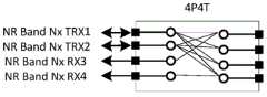
其中,本申请中的P端口英文全称是Port端口,本申请中用于天线开关中连接天线的端口的称谓;T端口英文全称是Throw端口,本申请中用于天线开关中连接射频模块的端口的称谓;举例来说,4P4T开关指的是有4个P端口连接天线,4个T端口连接射频电路。Wherein, the full English name of the P port in this application is Port port, which is used in this application for the title of the port connecting the antenna in the antenna switch; the full English name of the T port is the Throw port, which is used in this application for the port connecting the radio frequency module in the antenna switch. For example, a 4P4T switch means that there are 4 P ports connected to the antenna and 4 T ports connected to the RF circuit.
其中,本申请实施例所描述的多路选择开关中T端口与P端口之间的连接、全连接等概念,均是指T端口通过第一开关管连接P端口的状态,所述T端口和P端口可以是第二开关管的1个端口,该第一开关管用于控制T端口与P端口之间的单向导通(具体包括由T端口向P端口单向导通和由P端口向T端口单向导通),该第一开关管例如可以是由3个金属氧化物半导体MOS管组成的开关阵列(由于第一开关管断开时,若没有接地,寄生参数对其他导通的端口性能影响太大,所以这里设置为3个MOS管,断开时,两侧的2个都断开,中间的接地导通),该第二开关管用于使能对应的端口(T端口或P端口),该第二开关管例如可以是MOS管,该第一开关管和第二开关管的具体形态此处不做唯一限定。具体实现中,电子设备通过该第一开关管可以控制T端口与P端口之间的通路导通,具体的,电子设备可以设置专用控制器与该多路选择开关中的开关管连接。Wherein, concepts such as the connection between the T port and the P port, the full connection, etc. in the multiplexing switch described in the embodiments of the present application all refer to the state in which the T port is connected to the P port through the first switch tube. The P port can be one port of the second switch tube, and the first switch tube is used to control the unidirectional conduction between the T port and the P port (specifically including unidirectional conduction from the T port to the P port and from the P port to the T port). One-way conduction), the first switch tube can be, for example, a switch array composed of three metal-oxide-semiconductor MOS tubes (because when the first switch tube is disconnected, if there is no grounding, the parasitic parameters will affect the performance of other conductive ports It is too large, so it is set to 3 MOS tubes here. When disconnected, the two on both sides are disconnected, and the ground in the middle is turned on). The second switch tube is used to enable the corresponding port (T port or P port) , the second switch tube may be, for example, a MOS tube, and the specific forms of the first switch tube and the second switch tube are not limited here. In specific implementation, the electronic device can control the conduction between the T port and the P port through the first switch tube. Specifically, the electronic device can set a dedicated controller to connect with the switch tube in the multiplexer switch.
其中,所述支持通过探测参考信号SRS在发射天线间轮发,发送4端口SRS的功能是指电子设备通过轮训机制与基站交互确定每个天线对应的上行信道质量的过程。Wherein, the function of supporting the rotation of SRS among transmit antennas through sounding reference signals, and the function of sending 4-port SRS refers to the process in which the electronic device interacts with the base station through the polling mechanism to determine the quality of the uplink channel corresponding to each antenna.
下面对本申请实施例进行详细介绍。The embodiments of the present application will be described in detail below.
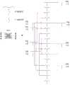
请参阅图1,图1是本申请实施例提供了一种多路选择开关10的结构示意图,该多路选择开关应用于支持单频双发的电子设备100,所述电子设备100包括多路选择开关10、射频电路20和天线系统30,所述天线系统30包括4支天线,所述多路选择开关10包括4个T端口和4个P端口,其中,所述4个T端口用于连接所述射频电路20,所述4个P端口用于连接所述天线系统30,所述4个T端口中的2个T端口全连接所述4个P端口;Please refer to FIG. 1. FIG. 1 is a schematic structural diagram of a
所述多路选择开关10用于连接所述射频电路20和所述天线系统30以实现所述电子设备的预设功能,所述预设功能为支持通过探测参考信号SRS在发射天线间的轮发,发送4端口SRS的功能。The
其中,所述电子设备具体可以是5G NR手机终端或其他5G NR终端设备,例如客户签约设备(Customer Premise Equipment,CPE)或者便携式宽带无线装置(Mobile Wifi,MIFI)。The electronic equipment may specifically be a 5G NR mobile phone terminal or other 5G NR terminal equipment, such as Customer Premise Equipment (CPE) or a portable broadband wireless device (Mobile Wifi, MIFI).
其中,所述单频双发模式是指电子设备最大能力支持单频段、UL双发射通路、或者DL4接收通路的工作模式。Wherein, the single-frequency dual-transmission mode refers to a working mode in which the electronic device has the maximum capability to support a single frequency band, a UL dual transmission path, or a DL4 reception path.
其中,所述多路选择开关10由场效应管构成,由于4个T端口中的2个T端口全连接所述4个P端口,且其它T端口只固定连接1支天线做接收使用,如此可减少4P4T开关内置场效应管数量/体积/成本,提升性能。下面对该部分做详细说明。Among them, the
举例来说,若该4个T端口中每个T端口均全连接4个P端口,则如图2所示的多路选择开关10的示例结构图,该多路选择开关10的场效应管的数量为4+4*4*3+4=56;若该4个T端口中仅有2个T端口全连接4个P端口,则如图3所示的多路选择开关的示例结构图,该多路选择开关10的场效应管的数量为4+(2*4+(4-2)*1)*3+4=38。For example, if each of the 4 T ports is fully connected to 4 P ports, then as shown in FIG. The number is 4+4*4*3+4=56; if only 2 T ports of the 4 T ports are fully connected to the 4 P ports, then the example structure diagram of the multiplexer switch shown in Figure 3 , the number of field effect transistors of the
此外,所述电子设备还可以进一步包括射频收发器,该射频收发器连接所述射频电路20,并与射频电路20、多路选择开关以及天线系统30组成该电子设备的射频系统。In addition, the electronic device may further include a radio frequency transceiver, which is connected to the radio frequency circuit 20 and forms a radio frequency system of the electronic device together with the radio frequency circuit 20 , the multiplexer switch and the
可见,通过限定T端口中全连接4个P端口的T端口的数量,可以有效减少电子设备射频系统的开关数量。也就是说,该全连接型T端口的数量对射频系统的性能有着较大影响。It can be seen that by limiting the number of T ports that are fully connected to four P ports in the T ports, the number of switches in the radio frequency system of the electronic device can be effectively reduced. That is to say, the number of the fully connected T ports has a great influence on the performance of the radio frequency system.
可以看出,本申请实施例提供一种多路选择开关,应用于支持单频双发的电子设备,该电子设备包括多路选择开关、射频电路和天线系统,该天线系统具体包括4支天线,多路选择开关包括4个T端口和4个P端口,且4个T端口中的2个T端口全连接所述4个P端口,该多路选择开关连接所述射频电路和所述天线系统以实现所述电子设备的支持通过探测参考信号SRS在发射天线间轮发。It can be seen that an embodiment of the present application provides a multiplexer switch, which is applied to an electronic device that supports single-frequency dual-transmission. The electronic device includes a multiplexer switch, a radio frequency circuit, and an antenna system, and the antenna system specifically includes four antennas , the multiplexing switch includes 4 T ports and 4 P ports, and 2 T ports in the 4 T ports are all connected to the 4 P ports, and the multiplexing switch is connected to the radio frequency circuit and the antenna. The system implements the support of the electronic device by rotating the sounding reference signal SRS among the transmitting antennas.
在一个实施例中,所述4个T端口包括2个第一T端口和2个第二T端口,其中,所述2个第一T端口分别全连接所述4个P端口,所述2个第二T端口分别连接所述4个P端口中的相应的1个P端口,所述第一T端口为所述4个T端口中至少支持发射功能的T端口,所述第二T端口为所述4个T端口中除所述第一T端口之外的仅支持接收功能的T端口。In an embodiment, the 4 T ports include 2 first T ports and 2 second T ports, wherein the 2 first T ports are fully connected to the 4 P ports respectively, and the 2 two second T ports are respectively connected to a corresponding one P port among the four P ports, the first T port is a T port that supports at least a transmission function among the four T ports, and the second T port is It is the T port that only supports the receiving function among the four T ports except the first T port.
可见,本示例中,由于多路选择开关由第一T端口和第二T端口组成,且第二T端口的数量不为0,故而该多路选择开关相对于全部T端口全连接P端口的形态减少了开关数量,即减少电子设备射频系统发射路径和/或接收路径的开关数量,减少路径损耗,从而提升发射功率/灵敏度,改善5G NR中数据传输速率,改善手机上下行覆盖范围,减少功耗和成本。It can be seen that in this example, since the multiplexing switch is composed of a first T port and a second T port, and the number of the second T ports is not 0, the multiplexing switch is fully connected to the P ports relative to all the T ports. The form reduces the number of switches, that is, reduces the number of switches in the transmit path and/or receive path of the radio frequency system of the electronic equipment, reduces the path loss, thereby improves the transmit power/sensitivity, improves the data transmission rate in 5G NR, improves the mobile phone uplink and downlink coverage, reduces power consumption and cost.
在一个实施例中,所述多路选择开关10为由38个场效应管组成的多路开关。In one embodiment, the multiplexing
在所述电子设备支持单频双发模式的情况下,该电子设备逻辑上包括4路接收信号处理电路和2路发射信号处理电路,且由于所述多路选择开关10包括4个T端口,4个T端口中包括2个第一T端口和2个第二T端口,多路选择开关对应的场效应管的数量为4+(2*4+(4-2)*1)*3+4=38。其中,逻辑上2路发射信号处理电路对应2个第一端口(支持信号收发功能),每个第一端口分别连接该多路选择开关中对应的第一T端口,同时,逻辑上该4路接收信号处理电路中有2路接收信号处理电路分别与2路发射信号处理电路集成至对应的第一端口,剩余2路接收信号处理电路对应2个第二端口(仅支持信号接收),每个第二端口连接多路选择开关中对应的第二T端口。此种情况下对应的射频电路20示例结构如图4A所示,对应的多路选择开关示例结构如图4B所示,其中,发射信号处理单路、接收信号处理电路的具体构成、多路选择开关中的相关词汇释义均与前述实施例类似,此处不再赘述,另外可以理解的是,上述射频电路20和多路选择开关10的匹配形态包括且不限于该附图结构,此处仅为示例。In the case that the electronic device supports the single-frequency dual-transmission mode, the electronic device logically includes 4 channels of receiving signal processing circuits and 2 channels of transmitting signal processing circuits, and since the
可见,本申请实施例提供的多路选择开关10能够使得电子设备支持单频双发模式,有利于简化5G NR终端支持4端口SRS switching时的射频架构,减少发射和接收路径的开关数量,减少路径损耗,从而提升发射功率/灵敏度,改善5G NR中数据传输速率,改善手机上下行覆盖范围,减少功耗。It can be seen that the
在一个实施例中,所述电子设备的所述射频电路20逻辑上包括2路发射信号处理电路和4路接收信号处理电路;In one embodiment, the radio frequency circuit 20 of the electronic device logically includes 2 channels of transmitting signal processing circuits and 4 channels of receiving signal processing circuits;
所述射频电路20物理形态上由2个独立电路模块组成;The radio frequency circuit 20 is physically composed of two independent circuit modules;
所述2个独立电路模块的每个信号收发端口用于连接1个第一T端口,所述2个独立电路模块的每个信号接收端口用于连接1个第二T端口。Each signal transceiving port of the two independent circuit modules is used to connect to a first T port, and each signal receiving port of the two independent circuit modules is used to connect a second T port.
可选的,在一个实施例中,所述电子设备的所述射频电路20逻辑上包括2路发射信号处理电路和4路接收信号处理电路;Optionally, in one embodiment, the radio frequency circuit 20 of the electronic device logically includes 2 channels of transmitting signal processing circuits and 4 channels of receiving signal processing circuits;
所述射频电路20物理形态上由3个独立电路模块组成;The radio frequency circuit 20 is physically composed of three independent circuit modules;
所述3个独立电路模块的每个信号收发端口用于连接1个第一T端口,所述3个独立电路模块的每个信号接收端口用于连接1个第二T端口。Each signal transceiving port of the three independent circuit modules is used to connect to a first T port, and each signal receiving port of the three independent circuit modules is used to connect to a second T port.
具体地,接收信号处理电路中的低噪声放大器LNA可以同时工作,因为功率低,耗电低,通过设计可以规避互相影响,所以同频段的多路接收信号处理电路中的多个LNA可在同一个电路模块中出现。但是由于同一个频段的2个功率放大器PA会出现同时工作的情况(对应UL MIMO模式),此时发射功率较大,2路信号会相互干扰,并且2个PA同时工作时影响散热效率,故而需要2个独立电路模块或3个独立电路模块来设置发射信号处理电路中的PA,有利于降低干扰,提高射频系统信号处理效率和散热效率。Specifically, the low noise amplifier LNAs in the received signal processing circuit can work at the same time. Because of low power and low power consumption, mutual influence can be avoided through design. Therefore, multiple LNAs in the multi-channel received signal processing circuit of the same frequency band can be operated at the same time. appears in a circuit block. However, because the two power amplifier PAs in the same frequency band will work at the same time (corresponding to the UL MIMO mode), the transmit power is large, the two signals will interfere with each other, and the heat dissipation efficiency will be affected when the two PAs work at the same time. Two independent circuit modules or three independent circuit modules are required to set the PA in the transmit signal processing circuit, which is beneficial to reduce interference and improve the signal processing efficiency and heat dissipation efficiency of the radio frequency system.
当所述射频电路20物理形态上由2个独立电路模块组成时,对应的电子设备的势力结构可以参考图5A至5B所示,以下分别进行描述。When the radio frequency circuit 20 is physically composed of two independent circuit modules, the power structure of the corresponding electronic equipment can be referred to as shown in FIGS. 5A to 5B , which will be described separately below.
在一个实施例中,如图5A所示,所述独立电路模块包括第一独立电路模块和第二独立电路模块,所述第一独立电路模块包括1路收发信号处理电路,所述第二独立电路模块包括1路收发信号处理电路和2路接收信号处理电路,所述收发信号处理电路的信号收发端口连接1个所述开关选择电路的10的第一T端口,所述接收信号处理电路的信号接收端口连接对应所述开关选择电路的10的第二T端口。In one embodiment, as shown in FIG. 5A , the independent circuit module includes a first independent circuit module and a second independent circuit module, the first independent circuit module includes 1 channel of signal processing circuits for transceiving, and the second independent circuit module The circuit module includes 1 channel of receiving and sending signal processing circuits and 2 channels of receiving signal processing circuits. The signal receiving port is connected to the second T port of 10 corresponding to the switch selection circuit.
在一个实施例中,如图5B所示,所述独立电路模块包括第一独立电路模块和第二独立电路模块,所述第一独立电路模块包括1路收发信号处理电路和1路接收信号处理电路,所述第二独立电路模块包括1路收发信号处理电路和1路接收信号处理电路,所述收发信号处理电路的信号收发端口连接对应所述开关选择电路的10的第一T端口,所述接收信号处理电路的信号接收端口连接对应所述开关选择电路的10的第二T端口。In one embodiment, as shown in FIG. 5B , the independent circuit module includes a first independent circuit module and a second independent circuit module, and the first independent circuit module includes 1 channel of receiving and sending signal processing circuit and 1 channel of receiving signal processing circuit The second independent circuit module includes 1 channel of transceiver signal processing circuit and 1 channel of receiving signal processing circuit, the signal transceiver port of the transceiver signal processing circuit is connected to the first T port of 10 corresponding to the switch selection circuit, so The signal receiving port of the received signal processing circuit is connected to the second T port of 10 corresponding to the switch selection circuit.
当所述射频电路20物理形态上由3个独立电路模块组成时,对应的电子设备的势力结构可以参考图5C至5D所示,以下分别进行描述。When the radio frequency circuit 20 is physically composed of three independent circuit modules, the power structure of the corresponding electronic device may be shown with reference to FIGS. 5C to 5D , which will be described separately below.
在一个实施例中,如图5C所示,所述独立电路模块包括第一独立电路模块、第二独立电路模块和第三独立电路模块,所述第一独立电路模块包括1路收发信号处理电路,所述第二独立电路模块包括1路收发信号处理电路,所述第一独立电路模块包括2路接收信号处理电路,所述收发信号处理电路的信号收发端口连接对应所述开关选择电路的10的第一T端口,所述接收信号处理电路的信号接收端口连接对应所述开关选择电路的10的第二T端口。In one embodiment, as shown in FIG. 5C , the independent circuit module includes a first independent circuit module, a second independent circuit module, and a third independent circuit module, and the first independent circuit module includes a channel of signal processing circuit for transmitting and receiving signals , the second independent circuit module includes 1 channel of receiving and dispatching signal processing circuits, the first independent circuit module includes 2 channels of receiving signal processing circuits, and the signal transmitting and receiving ports of the transmitting and receiving signal processing circuit are connected to 10 corresponding to the switch selection circuit. The first T port of the received signal processing circuit is connected to the second T port of 10 corresponding to the switch selection circuit.
在一个实施例中,如图5D所示,所述独立电路模块包括第一独立电路模块、第二独立电路模块和第三独立电路模块,所述第一独立电路模块包括1路收发信号处理电路和一路接收信号处理电路,所述第二独立电路模块包括1路收发信号处理电路,所述第一独立电路模块包括1路接收信号处理电路,所述收发信号处理电路的信号收发端口连接对应所述开关选择电路的10的第一T端口,所述接收信号处理电路的信号接收端口连接对应所述开关选择电路的10的第二T端口。In one embodiment, as shown in FIG. 5D , the independent circuit module includes a first independent circuit module, a second independent circuit module and a third independent circuit module, and the first independent circuit module includes 1 channel of signal processing circuit for transceiving and one channel of receiving signal processing circuit, the second independent circuit module includes one channel of receiving and dispatching signal processing circuit, the first independent circuit module includes one channel of receiving signal processing circuit, the signal transmitting and receiving port of the transmitting and receiving signal processing circuit is connected to the corresponding The first T port of 10 of the switch selection circuit, and the signal receiving port of the received signal processing circuit is connected to the second T port of 10 corresponding to the switch selection circuit.
其中,以上实施例中所涉及到的收发信号处理电路包括:功率放大器,低噪声放大器,单刀双掷开关、滤波器以及功率耦合器,其中,所述功率放大器和所述低噪声放大器并联后与所述单刀双掷开关连接,所述单刀双掷开关与所述滤波器连接,所述滤波器与所述功率耦合器连接,所述功率耦合器连接1个所述多路选择开关10的第一T端口。Wherein, the transceiver signal processing circuit involved in the above embodiment includes: a power amplifier, a low noise amplifier, a single-pole double-throw switch, a filter and a power coupler, wherein the power amplifier and the low-noise amplifier are connected in parallel with each other. The SPDT switch is connected, the SPDT switch is connected with the filter, the filter is connected with the power coupler, and the power coupler is connected with the No. A T port.
以上实施例中所涉及到的接收信号处理电路包括:低噪声放大器和滤波器,所述低噪声放大器和所述滤波器连接,所述滤波器连接1个所述多路选择开关10的第二T端口。The received signal processing circuit involved in the above embodiments includes: a low-noise amplifier and a filter, the low-noise amplifier is connected to the filter, and the filter is connected to the second one of the multiplexer switches 10 T port.
所述收发信号处理电路的信号收发端口对应独立电路模块的信号收发端口,其连接多路选择开关的相应的第一T端口;接收信号处理电路的信号接收端口对应独立电路模块的信号接收端口,其连接多路选择开关的相应的第二T端口。The signal transceiving port of the transceiving signal processing circuit corresponds to the signal transceiving port of the independent circuit module, which is connected to the corresponding first T port of the multiplexing switch; the signal receiving port of the receiving signal processing circuit corresponds to the signal receiving port of the independent circuit module, It is connected to the corresponding second T port of the multiplexer switch.
参照图5A,当所述独立电路模块包括第一独立电路模块和第二独立电路模块时,所述第一独立电路模块包括第一收发信号处理电路,所述第二独立电路模块包括第二收发信号处理电路、第一接收信号处理电路、第二接收信号处理电路。其中,第一收发信号处理电路的功率耦合器连接开关选择电路的10的一个第一T端口,第一收发信号处理电路的低噪声放大器和功率放大器分别连接射频收发器的PRX-NX(NX频段的第四接收端口)引脚以及TX-CH0-NX(NX频段的第一发射通路的发射端口)引脚。第二收发信号处理电路的功率耦合器连接开关选择电路的10的另一个第一T端口,第二收发信号处理电路的低噪声放大器和功率放大器分别连接射频收发器的RX1-NX(NX频段的第一接收端口)引脚以及TX-CH1-NX(NX频段的第二发射通路的发射端口)引脚。第一接收信号处理电路的滤波器连接所述开关选择电路的10一个第二T端口,第一接收信号处理电路的低噪声放大器连接所述射频收发器的的RX2-NX(NX频段的第二接收端口)引脚。第二接收信号处理电路的滤波器连接所述开关选择电路的10另一个第二T端口,第二接收信号处理电路的低噪声放大器连接所述射频收发器的的RX3-NX(NX频段的第三接收端口)引脚。5A , when the independent circuit module includes a first independent circuit module and a second independent circuit module, the first independent circuit module includes a first transceiver signal processing circuit, and the second independent circuit module includes a second transceiver A signal processing circuit, a first received signal processing circuit, and a second received signal processing circuit. The power coupler of the first transceiving signal processing circuit is connected to a first T port of the
电子设备通过控制开关管可以控制多路选择开关(第一独立电路模块和第二独立电路模块)的T端口连接P端口的状态以实现所述电子设备支持通过探测参考信号SRS在发射天线间的轮发,发送4端口SRS的功能。The electronic device can control the state of the connection between the T port and the P port of the multiplexing switch (the first independent circuit module and the second independent circuit module) by controlling the switch tube, so as to realize that the electronic device supports the transmission between the transmitting antennas through the sounding reference signal SRS. Round-robin, the function of sending 4-port SRS.
图5B至图5D所示的电子设备中射频收发器、射频电路以及多路选择开关的连接关系可以参照图5A所示的电子设备中射频收发器、射频电路以及多路选择开关的连接关系的描述,此处不再赘述。For the connection relationship between the radio frequency transceiver, the radio frequency circuit and the multiplexing switch in the electronic device shown in FIGS. 5B to 5D, reference may be made to the connection relationship between the radio frequency transceiver, the radio frequency circuit and the multiplexing switch in the electronic device shown in FIG. 5A. description, which will not be repeated here.
可以理解的是,上述接收信号处理电路和发射信号处理电路的具体实现方式可以是多种多样的,本申请实施例不做唯一限定。It can be understood that, the specific implementation manners of the above-mentioned receiving signal processing circuit and transmitting signal processing circuit may be various, and the embodiment of the present application does not make a unique limitation.
在一个实施例中,所述4支天线包括第一天线、第二天线、第三天线和第四天线,所述第一天线、第二天线、第三天线和所述第四天线均为支持第五代新空口5G NR频段的天线。In one embodiment, the four antennas include a first antenna, a second antenna, a third antenna, and a fourth antenna, and the first antenna, the second antenna, the third antenna, and the fourth antenna all support Antennas for the fifth-generation NR 5G NR band.
其中,所述5G NR频段例如可以包括3.3GHz-3.8GHz,4.4GHz-5GHz。Wherein, the 5G NR frequency band may include, for example, 3.3GHz-3.8GHz and 4.4GHz-5GHz.
在一个实施例中,所述4支天线包括第一天线、第二天线、第三天线和第四天线,所述第一天线和所述第四天线为支持LTE频段和5G NR的频段的天线,所述第二天线和所述第三天线为支持5G NR频段的天线。In one embodiment, the four antennas include a first antenna, a second antenna, a third antenna, and a fourth antenna, and the first antenna and the fourth antenna are antennas supporting LTE frequency bands and 5G NR frequency bands , the second antenna and the third antenna are antennas supporting the 5G NR frequency band.
其中,第一和第四天线是为了支持LTE终端上个别频段的DL 4x4 MIMO。其2支接收天线与5G NR的天线共用。所述LTE频段例如可以包括1880-1920MHz、2496-2690MHz。Among them, the first and fourth antennas are used to support DL 4x4 MIMO of individual frequency bands on the LTE terminal. Its two receiving antennas are shared with those of 5G NR. The LTE frequency band may include, for example, 1880-1920 MHz and 2496-2690 MHz.
在一个实施例中,如图6所示,所述天线系统30还包括第一合路器和第二合路器,其中:In one embodiment, as shown in FIG. 6 , the
所述第一合路器的第一端口用于连接所述第一天线,所述第一合路器的第二端口用于连接所述电子设备的LTE 4x4 MIMO中的第一接收通路,所述第一合路器的第三端口用于连接所述多路选择开关10中对应的P端口;The first port of the first combiner is used to connect to the first antenna, and the second port of the first combiner is used to connect to the first receiving channel in the LTE 4x4 MIMO of the electronic device, so The third port of the first combiner is used to connect the corresponding P port in the
所述第二合路器的第一端口用于连接所述第四天线,所述第二合路器的第二端口用于连接所述电子设备的LTE 4x4 MIMO中的第二接收通路,所述第二合路器的第三端口用于连接所述多路选择开关10中对应的P端口。The first port of the second combiner is used to connect to the fourth antenna, and the second port of the second combiner is used to connect to the second receiving channel in the LTE 4x4 MIMO of the electronic device, so The third port of the second combiner is used to connect to the corresponding P port in the
其中,所述LTE 4*4MIMO是下行LTE接收电路,可以定义为第三接收通路。因为当前LTE已经有2路接收。在支持LTE 4x4 MIMO时,会有增加第三和第四接收通道。The LTE 4*4MIMO is a downlink LTE receiving circuit, which can be defined as a third receiving path. Because the current LTE already has 2 channels of reception. When supporting LTE 4x4 MIMO, a third and fourth receive channel will be added.
其中,电子设备会根据实际4支天线情况,将性能较好的1支天线留给电路中主集接收PRX做待机使用,且开关中第一T端口具备收发功能的,即其可以做TX和PRX功能,可任意切换天线,因此不需要对此处的共用天线做连接端口的限制。Among them, according to the actual situation of the four antennas, the electronic equipment will leave the antenna with better performance to the main set receiving PRX in the circuit for standby use, and the first T port in the switch has the function of sending and receiving, that is, it can be used for TX and With the PRX function, the antenna can be switched arbitrarily, so there is no need to limit the connection port for the shared antenna here.
在一个实施例中,如图7所示,所述天线系统30还包括第一单刀双掷SPDT开关和第二SPDT开关,其中,所述第一SPDT开关的第一端口用于连接所述第一天线,所述第一SPDT开关的第二端口用于连接所述电子设备的LTE 4x4MIMO中的第一接收通路,所述第一SPDT开关的第三端口用于连接所述多路选择开关10中对应的P端口;所述第二SPDT开关的第一端口用于连接所述第四天线,所述第二SPDT开关的第二端口用于连接所述电子设备的LTE4x4MIMO中的第二接收通路,所述第二SPDT开关的第三端口用于连接所述多路选择开关10中对应的P端口。In one embodiment, as shown in FIG. 7 , the
请参阅图8,图8是本申请实施例提供了一种射频系统的结构示意图,该射频系统包括天线系统、射频电路以及上述任一实施例所述的多路选择开关;Please refer to FIG. 8. FIG. 8 is a schematic structural diagram of a radio frequency system provided by an embodiment of the present application. The radio frequency system includes an antenna system, a radio frequency circuit, and the multiplexing switch described in any of the above embodiments;
所述多路选择开关用于连接所述射频电路和所述天线系统以实现电子设备的预设功能,所述预设功能为支持通过探测参考信号SRS在发射天线间轮发,发送4端口SRS的功能。The multiplexer switch is used to connect the radio frequency circuit and the antenna system to realize the preset function of the electronic device, and the preset function is to support the rotation between the transmitting antennas through the sounding reference signal SRS, and send the 4-port SRS function.
请参阅图9,图9是本申请实施例提供了一种无线通信设备的结构示意图,该无线通信设备包括天线系统、射频电路以及上述任一实施例所述的多路选择开关;Please refer to FIG. 9. FIG. 9 is a schematic structural diagram of a wireless communication device provided by an embodiment of the present application, where the wireless communication device includes an antenna system, a radio frequency circuit, and the multiplexing switch described in any of the foregoing embodiments;
所述多路选择开关用于连接所述射频电路和所述天线系统以实现所述无线通信设备的预设功能,所述预设功能为支持通过探测参考信号SRS在发射天线间轮发,发送4端口SRS的功能;The multiplexing switch is used to connect the radio frequency circuit and the antenna system to realize a preset function of the wireless communication device, and the preset function is to support the rotation between the transmitting antennas through the sounding reference signal SRS, sending 4-port SRS function;
所述无线通信设备至少包括以下任意一种:电子设备、基站。The wireless communication device includes at least any one of the following: an electronic device and a base station.
此外,如图10所示,本申请实施例所描述的天线系统中的4支天线还可以被该电子设备的无线充电接收器所复用,具体的,该无线充电接收器包括接收天线、接收控制电路,该接收天线与无线充电发射器的发射天线匹配(频率相同或相近情况下谐振,以辐射性谐振磁耦合的方式,将能量通过无线传送的方式传输),接收控制电路通过环形阵列天线将能量转变为直流电DC输出给电池充电,接收控制电路能够动态调整该环形阵列天线的频率,并使之与无线充电发射器的发射天线的频率匹配,以实现配对充电,或者,实时与无线充电发射器进行频率变化范围交互,以实现“专属加密”无线充电模式。In addition, as shown in FIG. 10 , the four antennas in the antenna system described in the embodiments of the present application can also be multiplexed by the wireless charging receiver of the electronic device. Specifically, the wireless charging receiver includes a receiving antenna, a receiving Control circuit, the receiving antenna is matched with the transmitting antenna of the wireless charging transmitter (resonant at the same or similar frequencies, and the energy is transmitted wirelessly in the form of radiative resonance magnetic coupling), and the receiving control circuit passes through the loop array antenna. The energy is converted into direct current DC output to charge the battery, and the receiving control circuit can dynamically adjust the frequency of the loop array antenna and make it match the frequency of the transmitting antenna of the wireless charging transmitter to achieve paired charging, or, real-time and wireless charging The transmitter interacts with frequency varying ranges to enable "proprietary encryption" wireless charging mode.
其中,所述接收天线可以是由4支天线中的至少1支天线所组成的天线(多支情况下天线与天线之间通过开关选通)。Wherein, the receiving antenna may be an antenna composed of at least one antenna among the four antennas (in the case of multiple antennas, a switch is used to select between the antennas).
例如:如图11所示,该接收天线为由上述4支天线构成的环形阵列天线,4支天线具体包括天线1、天线2、天线3、天线4,其中天线1和天线4支持LTE和5G NR频段,天线2和天线3仅支持5G NR频段,天线1的端口和天线4的端口作为该环形阵列天线的端口,其中相邻天线之间通过具有隔离功能的选通电路170连接,该选通电路170包括隔离片171和开关172,隔离片171为导体,开关172还连接控制器,电子设备在无线充电模式下可以连通每个选通电路170的开关172,以形成环形阵列天线接收能量。通过在天线间加入隔离片171,该选通电路170一方面降低了电子设备在正常通信模式下的多天线间的互耦性,提升了多天线间的隔离度,优化了天线性能,另一方面通过开关171能够将多天线串联形成环形阵列天线,以便于更好的匹配发射天线以传输能量,此外,由于天线1和天线4能力强于天线2和天线3,如此设置的环形阵列天线可以尽可能减少能量传输损耗。For example, as shown in Figure 11, the receiving antenna is a ring array antenna composed of the above four antennas. The four antennas specifically include Antenna 1, Antenna 2, Antenna 3, and Antenna 4. Antenna 1 and Antenna 4 support LTE and 5G. NR frequency band, antenna 2 and antenna 3 only support 5G NR frequency band, the port of antenna 1 and the port of antenna 4 are used as the ports of the loop array antenna, wherein adjacent antennas are connected through the
以上是本申请实施例的实施方式,应当指出,对于本技术领域的普通技术人员来说,在不脱离本申请实施例原理的前提下,还可以做出若干改进和润饰,这些改进和润饰也视为本申请的保护范围。The above is the implementation of the embodiments of the present application. It should be pointed out that for those of ordinary skill in the art, without departing from the principles of the embodiments of the present application, several improvements and modifications can also be made. These improvements and modifications are also It is regarded as the protection scope of this application.
Claims (15)
Priority Applications (4)
| Application Number | Priority Date | Filing Date | Title |
|---|---|---|---|
| CN201810220614.9ACN108462497B (en) | 2018-03-16 | 2018-03-16 | Multi-way selector switch and related products |
| PCT/CN2018/113769WO2019174267A1 (en) | 2018-03-16 | 2018-11-02 | Multiway switch, radio frequency system, and electronic device |
| US16/183,707US10567029B2 (en) | 2018-03-16 | 2018-11-07 | Multiway switch, radio frequency system, and electronic device |
| EP18205591.3AEP3540967B1 (en) | 2018-03-16 | 2018-11-12 | Multiway switch, radio frequency system, and electronic device |
Applications Claiming Priority (1)
| Application Number | Priority Date | Filing Date | Title |
|---|---|---|---|
| CN201810220614.9ACN108462497B (en) | 2018-03-16 | 2018-03-16 | Multi-way selector switch and related products |
Publications (2)
| Publication Number | Publication Date |
|---|---|
| CN108462497A CN108462497A (en) | 2018-08-28 |
| CN108462497Btrue CN108462497B (en) | 2020-09-01 |
Family
ID=63236767
Family Applications (1)
| Application Number | Title | Priority Date | Filing Date |
|---|---|---|---|
| CN201810220614.9AExpired - Fee RelatedCN108462497B (en) | 2018-03-16 | 2018-03-16 | Multi-way selector switch and related products |
Country Status (4)
| Country | Link |
|---|---|
| US (1) | US10567029B2 (en) |
| EP (1) | EP3540967B1 (en) |
| CN (1) | CN108462497B (en) |
| WO (1) | WO2019174267A1 (en) |
Families Citing this family (13)
| Publication number | Priority date | Publication date | Assignee | Title |
|---|---|---|---|---|
| CN108462499A (en) | 2018-03-16 | 2018-08-28 | 广东欧珀移动通信有限公司 | Multi-way selector switch and related products |
| CN108599777B (en)* | 2018-03-16 | 2020-09-01 | Oppo广东移动通信有限公司 | Multi-way selector switch and related products |
| CN108199726B (en)* | 2018-03-16 | 2020-08-28 | Oppo广东移动通信有限公司 | Multi-way selector switch and related products |
| CN108512556B (en)* | 2018-03-16 | 2020-06-16 | Oppo广东移动通信有限公司 | Multi-way selector switch, radio frequency system and wireless communication equipment |
| CN108199729B (en)* | 2018-03-16 | 2020-09-04 | Oppo广东移动通信有限公司 | Multi-way selector switch, radio frequency system and wireless communication equipment |
| CN108964677B (en) | 2018-07-23 | 2020-12-08 | Oppo广东移动通信有限公司 | Radio frequency system, antenna switching control method and related products |
| CN109802699B (en)* | 2019-01-24 | 2021-02-09 | 维沃移动通信有限公司 | Signal receiving and transmitting device and terminal equipment |
| CN113726359B (en)* | 2020-05-26 | 2023-08-15 | Oppo广东移动通信有限公司 | RF PA Mid devices, RF systems and communication equipment |
| CN111756396A (en)* | 2020-07-15 | 2020-10-09 | 维沃移动通信有限公司 | Radio frequency circuit, electronic device and control method |
| CN213403006U (en)* | 2020-11-12 | 2021-06-08 | Oppo广东移动通信有限公司 | Radio frequency system and customer premises equipment |
| CN115225111B (en)* | 2020-11-27 | 2023-12-15 | Oppo广东移动通信有限公司 | Radio frequency system, antenna switching method and customer premises equipment |
| US11546905B1 (en)* | 2021-03-26 | 2023-01-03 | Vivint, Inc. | WiFi routers and switching |
| CN114400423B (en)* | 2022-01-21 | 2023-04-25 | 苏州悉芯射频微电子有限公司 | Millimeter wave switch based on coupler structure and design method |
Citations (3)
| Publication number | Priority date | Publication date | Assignee | Title |
|---|---|---|---|---|
| CN1323025A (en)* | 2000-05-09 | 2001-11-21 | 夏普公司 | Data signal line drive circuit, image display device and electronic equipment |
| WO2010019012A2 (en)* | 2008-08-15 | 2010-02-18 | Samsung Electronics Co., Ltd | Method for transmitting uplink sounding reference signal for lte system |
| CN102917460A (en)* | 2011-08-03 | 2013-02-06 | 中兴通讯股份有限公司 | Method and system for time division multiplexing of transmitting channels |
Family Cites Families (13)
| Publication number | Priority date | Publication date | Assignee | Title |
|---|---|---|---|---|
| US8099132B2 (en) | 2007-08-15 | 2012-01-17 | Qualcomm Incorporated | Antenna switching and uplink sounding channel measurement |
| US20100002345A1 (en)* | 2008-07-02 | 2010-01-07 | Skyworks Solutions, Inc. | Radio frequency switch electrostatic discharge protection circuit |
| CN101867402B (en)* | 2010-05-04 | 2014-01-29 | 西安交通大学 | A MIMO system with adaptive antenna selection and its application method |
| CN202103661U (en) | 2011-07-15 | 2012-01-04 | 惠州市正源微电子有限公司 | Multi-mode multi-frequency handset radio frequency front module |
| US8970323B2 (en)* | 2011-07-19 | 2015-03-03 | Infineon Technologies Ag | Circuit arrangement with an antenna switch and a bandstop filter and corresponding method |
| US9070974B2 (en)* | 2012-05-21 | 2015-06-30 | Qualcomm Incorporated | Antenna switching devices, methods, and systems for simultaneous communication |
| US9344174B2 (en) | 2012-05-21 | 2016-05-17 | Qualcomm Incorporated | Systems, apparatus, and methods for antenna selection |
| US10009058B2 (en)* | 2012-06-18 | 2018-06-26 | Qorvo Us, Inc. | RF front-end circuitry for receive MIMO signals |
| CN103905104B (en)* | 2012-12-28 | 2017-12-19 | 中兴通讯股份有限公司 | It is a kind of according to the multi-antenna sending method and terminal of detection reference signal and base station |
| US9172441B2 (en) | 2013-02-08 | 2015-10-27 | Rf Micro Devices, Inc. | Front end circuitry for carrier aggregation configurations |
| US20170195004A1 (en) | 2016-01-06 | 2017-07-06 | Le Holdings (Beijing) Co., Ltd. | Antenna apparatus applied to mobile terminal and mobile terminal |
| CN107733508B (en)* | 2017-08-30 | 2020-10-13 | 努比亚技术有限公司 | Antenna switching method, multi-antenna terminal and computer readable storage medium |
| CN108494413B (en)* | 2018-03-16 | 2020-03-17 | Oppo广东移动通信有限公司 | Electronic equipment with multi-way selection switch |
- 2018
- 2018-03-16CNCN201810220614.9Apatent/CN108462497B/ennot_activeExpired - Fee Related
- 2018-11-02WOPCT/CN2018/113769patent/WO2019174267A1/ennot_activeCeased
- 2018-11-07USUS16/183,707patent/US10567029B2/enactiveActive
- 2018-11-12EPEP18205591.3Apatent/EP3540967B1/enactiveActive
Patent Citations (3)
| Publication number | Priority date | Publication date | Assignee | Title |
|---|---|---|---|---|
| CN1323025A (en)* | 2000-05-09 | 2001-11-21 | 夏普公司 | Data signal line drive circuit, image display device and electronic equipment |
| WO2010019012A2 (en)* | 2008-08-15 | 2010-02-18 | Samsung Electronics Co., Ltd | Method for transmitting uplink sounding reference signal for lte system |
| CN102917460A (en)* | 2011-08-03 | 2013-02-06 | 中兴通讯股份有限公司 | Method and system for time division multiplexing of transmitting channels |
Also Published As
| Publication number | Publication date |
|---|---|
| EP3540967A1 (en) | 2019-09-18 |
| CN108462497A (en) | 2018-08-28 |
| WO2019174267A1 (en) | 2019-09-19 |
| EP3540967B1 (en) | 2020-08-26 |
| US10567029B2 (en) | 2020-02-18 |
| US20190288731A1 (en) | 2019-09-19 |
Similar Documents
| Publication | Publication Date | Title |
|---|---|---|
| CN108199726B (en) | Multi-way selector switch and related products | |
| CN108462506B (en) | Multiplexer switches, radio frequency systems and wireless communication equipment | |
| CN108512556B (en) | Multi-way selector switch, radio frequency system and wireless communication equipment | |
| CN108199730B (en) | Multiplexer switches, radio frequency systems, and wireless communication equipment | |
| CN108462497B (en) | Multi-way selector switch and related products | |
| CN108199729B (en) | Multi-way selector switch, radio frequency system and wireless communication equipment | |
| CN108599779B (en) | Wireless communication device with multiple-way selector switch | |
| CN108512567B (en) | Multiplexer switches, radio frequency systems and wireless communication equipment | |
| CN108494461B (en) | Wireless communication device | |
| CN112134588B (en) | Multi-way selector switch and related products | |
| CN108494413B (en) | Electronic equipment with multi-way selection switch | |
| CN108599777B (en) | Multi-way selector switch and related products | |
| CN108199727A (en) | Multidiameter option switch and Related product | |
| CN108462499A (en) | Multi-way selector switch and related products | |
| CN108923790A (en) | Multi-way selector switch, radio frequency system and wireless communication equipment | |
| CN108599778B (en) | Multi-way selector switch, radio frequency system and wireless communication equipment | |
| CN108900201B (en) | Multi-way selector switch, radio frequency system and electronic equipment | |
| CN108880602A (en) | Multi-way selector switch and related products | |
| CN109039345A (en) | Multi-way selector switch and related products | |
| CN108923792B (en) | Multi-way selector switch and related products | |
| CN108964675A (en) | Multi-way selector switch and related products | |
| CN108390693A (en) | Multidiameter option switch and Related product | |
| CN108923793A (en) | Multi-way selector switch and related products | |
| CN109039367A (en) | Multi-way selector switch and related products | |
| CN108599780A (en) | Multi-channel selector switch and wireless communication device |
Legal Events
| Date | Code | Title | Description |
|---|---|---|---|
| PB01 | Publication | ||
| PB01 | Publication | ||
| SE01 | Entry into force of request for substantive examination | ||
| SE01 | Entry into force of request for substantive examination | ||
| REG | Reference to a national code | Ref country code:HK Ref legal event code:DE Ref document number:1252753 Country of ref document:HK | |
| CB02 | Change of applicant information | ||
| CB02 | Change of applicant information | Address after:Changan town in Guangdong province Dongguan 523860 usha Beach Road No. 18 Applicant after:GUANGDONG OPPO MOBILE TELECOMMUNICATIONS Corp.,Ltd. Address before:Changan town in Guangdong province Dongguan 523860 usha Beach Road No. 18 Applicant before:GUANGDONG OPPO MOBILE TELECOMMUNICATIONS Corp.,Ltd. | |
| GR01 | Patent grant | ||
| GR01 | Patent grant | ||
| CF01 | Termination of patent right due to non-payment of annual fee | ||
| CF01 | Termination of patent right due to non-payment of annual fee | Granted publication date:20200901 |