CN108432049B - Effective Planar Phased Array Antenna Assemblies - Google Patents
Effective Planar Phased Array Antenna AssembliesDownload PDFInfo
- Publication number
- CN108432049B CN108432049BCN201680045476.4ACN201680045476ACN108432049BCN 108432049 BCN108432049 BCN 108432049BCN 201680045476 ACN201680045476 ACN 201680045476ACN 108432049 BCN108432049 BCN 108432049B
- Authority
- CN
- China
- Prior art keywords
- panel
- band
- phased array
- array antenna
- radiating elements
- Prior art date
- Legal status (The legal status is an assumption and is not a legal conclusion. Google has not performed a legal analysis and makes no representation as to the accuracy of the status listed.)
- Expired - Fee Related
Links
Images


Classifications
- H—ELECTRICITY
- H01—ELECTRIC ELEMENTS
- H01Q—ANTENNAS, i.e. RADIO AERIALS
- H01Q21/00—Antenna arrays or systems
- H01Q21/06—Arrays of individually energised antenna units similarly polarised and spaced apart
- H01Q21/061—Two dimensional planar arrays
- H01Q21/064—Two dimensional planar arrays using horn or slot aerials
- H—ELECTRICITY
- H01—ELECTRIC ELEMENTS
- H01Q—ANTENNAS, i.e. RADIO AERIALS
- H01Q13/00—Waveguide horns or mouths; Slot antennas; Leaky-waveguide antennas; Equivalent structures causing radiation along the transmission path of a guided wave
- H01Q13/10—Resonant slot antennas
- H01Q13/18—Resonant slot antennas the slot being backed by, or formed in boundary wall of, a resonant cavity ; Open cavity antennas
- H—ELECTRICITY
- H01—ELECTRIC ELEMENTS
- H01Q—ANTENNAS, i.e. RADIO AERIALS
- H01Q21/00—Antenna arrays or systems
- H01Q21/0006—Particular feeding systems
- H01Q21/0037—Particular feeding systems linear waveguide fed arrays
- H01Q21/0043—Slotted waveguides
- H01Q21/005—Slotted waveguides arrays
- H—ELECTRICITY
- H01—ELECTRIC ELEMENTS
- H01Q—ANTENNAS, i.e. RADIO AERIALS
- H01Q21/00—Antenna arrays or systems
- H01Q21/30—Combinations of separate antenna units operating in different wavebands and connected to a common feeder system
- H—ELECTRICITY
- H01—ELECTRIC ELEMENTS
- H01Q—ANTENNAS, i.e. RADIO AERIALS
- H01Q5/00—Arrangements for simultaneous operation of antennas on two or more different wavebands, e.g. dual-band or multi-band arrangements
- H01Q5/40—Imbricated or interleaved structures; Combined or electromagnetically coupled arrangements, e.g. comprising two or more non-connected fed radiating elements
- H01Q5/42—Imbricated or interleaved structures; Combined or electromagnetically coupled arrangements, e.g. comprising two or more non-connected fed radiating elements using two or more imbricated arrays
Landscapes
- Physics & Mathematics (AREA)
- Electromagnetism (AREA)
- Variable-Direction Aerials And Aerial Arrays (AREA)
- Waveguide Aerials (AREA)
Abstract
Description
Translated fromChinese背景技术Background technique
技术领域technical field
本申请一般涉及相控阵列天线,并且更具体地涉及适用于双波段合成孔径雷达的有效相控阵列天线。This application relates generally to phased array antennas, and more particularly to efficient phased array antennas suitable for use in dual-band synthetic aperture radars.
介绍introduce
多频率多极化合成孔径雷达(SAR)是理想的,但是有效载荷、数据速率、预算、空间分辨率、覆盖面积等的局限性对于实现(尤其是在星载平台上的)多频率全极化SAR提出了重大的技术挑战。Multi-frequency multi-polarization synthetic aperture radar (SAR) is ideal, but limitations of payload, data rate, budget, spatial resolution, coverage area, etc. Chemical SAR presents significant technical challenges.
航天飞机成像雷达SIR-C是运行在多于一个频带的SAR的示例。然而,这两个天线没有共同的孔,而且质量太大,无法在国际空间站(ISS)或小型卫星(SmallSAT)平台上部署。The Space Shuttle Imaging Radar SIR-C is an example of a SAR operating in more than one frequency band. However, the two antennas do not have a common hole and are too massive to be deployed on the International Space Station (ISS) or Small Satellite (SmallSAT) platforms.
天线构造,尤其是在星载平台上的天线构造,由于在面积和厚度上的各种原因而受到限制。例如,运载火箭的物理限制能够对天线的尺寸施加约束。对天线的面积的约束反过来能够对方向性施加约束。由于这个原因,效率能够成为天线设计的主要推动力,寻找减少天线损耗的方法可能变得重要。Antenna construction, especially on a spaceborne platform, is limited for various reasons in area and thickness. For example, physical limitations of launch vehicles can impose constraints on the size of the antenna. Constraining the area of the antenna can in turn impose constraints on directivity. For this reason, efficiency can be a major driver in antenna design, and finding ways to reduce antenna losses may become important.
现有的设计多频相控阵列天线的方法能够包括使用微带阵列。这些可能与高损耗相关联,从而导致效率低下。Existing methods of designing multi-frequency phased array antennas can include the use of microstrip arrays. These can be associated with high losses, leading to inefficiencies.
本申请中所描述的技术涉及设计和构建适于ISS和SmallSAT部署的成本有效、高效率、结构合理的SAR天线,该SAR天线在至少一个频带上受到厚度以及双频操作和全极化的约束。The techniques described in this application relate to the design and construction of cost-effective, high-efficiency, well-structured SAR antennas suitable for ISS and SmallSAT deployments that are constrained by thickness and dual-frequency operation and full polarization in at least one frequency band .
除需要小型、高效率的雷达天线之外,对商用微波和毫米波天线有类似的需求,诸如在无线电点对点和点对多点链路应用中。通常,这些应用使用反射器天线。但是,反射器和馈电喇叭在一起呈现相当大的厚度。In addition to the need for small, high-efficiency radar antennas, there is a similar need for commercial microwave and millimeter-wave antennas, such as in radio point-to-point and point-to-multipoint link applications. Typically, reflector antennas are used for these applications. However, the reflector and feed horn together present a considerable thickness.
一种较小型的替代方案是微带平面阵列。通常需要几个层,并且有时需要特殊的布置来防止平行板模式在不同层之间传播。这些特征连同低损耗材料和支撑结构的成本一起使得该方法的吸引力降低。减少微带阵列的损耗也是困难的,尤其是在高频处。所以,虽然使用微带阵列能够减小天线的厚度,但天线是有损的,并且天线的面积需要大于反射器天线以获得相同的增益。A smaller alternative is the microstrip planar array. Several layers are usually required, and sometimes special arrangements are required to prevent the propagation of the parallel-plate mode between the different layers. These features, along with the cost of low-loss materials and support structures, make this approach less attractive. It is also difficult to reduce losses in microstrip arrays, especially at high frequencies. Therefore, although the thickness of the antenna can be reduced by using a microstrip array, the antenna is lossy and the area of the antenna needs to be larger than that of the reflector antenna to obtain the same gain.
发明内容SUMMARY OF THE INVENTION
平面相控阵列天线组件可以被概述为包括第一面板,第一面板包括用于第一频段的第一多个辐射槽和用于第二频段的第二多个辐射槽;第二面板;插在第一面板和第二面板之间的结构,所述结构包括处于第一频段的第三多个辐射元件和处于第二频段的第四多个辐射元件,所述结构还包括用于第三多个辐射元件的第一馈电网络和用于第四多个辐射元件的第二馈电网络;以及第三面板,其中,第二面板插在所述结构和第三面板之间。The planar phased array antenna assembly can be summarized as including a first panel including a first plurality of radiation slots for a first frequency band and a second plurality of radiation slots for a second frequency band; a second panel; an insert A structure between the first panel and the second panel, the structure including a third plurality of radiating elements in the first frequency band and a fourth plurality of radiating elements in the second frequency band, the structure further including a third plurality of radiating elements for a third frequency band a first feed network for a plurality of radiating elements and a second feed network for a fourth plurality of radiating elements; and a third panel, wherein the second panel is interposed between the structure and the third panel.
该组件可以是在结构上自支撑的。整个组件基本上可以由辐射元件和馈电网络组成。第一面板、第二面板、第三面板和所述结构均可以包括机器加工的铝。第三多个辐射元件中的每一个可以包括耦接到第一多个辐射槽中的至少一个的折叠腔。第四多个辐射元件中的每一个可以包括耦接到第二多个辐射槽中的至少一个的至少一个波导,并且第三面板可以包括波导终端。至少一个波导中的每一个可以是脊形波导。第一频段可以是L波段,并且第二频段可以是X波段。第一馈电网络可以包括至少一个带线以及耦接到第三多个辐射元件中的每一个的至少一个探针。第二馈电网络可以包括耦接到第四多个辐射元件中的每一个的至少一个同轴电缆。第一多个辐射槽可以包括多个交叉槽,所述交叉槽可操作来辐射水平极化的微波和垂直极化的微波。多个交叉槽可以在平面内和穿过平面取向中的至少一个上展开。折叠腔可以至少部分地以电介质材料填充。第一面板、第二面板和第三面板以及插在第一面板与第二面板之间的结构可以构成平面相控阵列天线组件的唯一支撑结构,在没有任何附加结构的情况下,该唯一支撑结构自身支撑所述平面相控阵列天线组件。The assembly may be structurally self-supporting. The entire assembly can basically consist of radiating elements and a feeding network. The first panel, the second panel, the third panel, and the structure may each comprise machined aluminum. Each of the third plurality of radiating elements may include a folded cavity coupled to at least one of the first plurality of radiating slots. Each of the fourth plurality of radiating elements may include at least one waveguide coupled to at least one of the second plurality of radiating slots, and the third panel may include waveguide terminations. Each of the at least one waveguide may be a ridge waveguide. The first frequency band may be the L-band, and the second frequency band may be the X-band. The first feed network may include at least one stripline and at least one probe coupled to each of the third plurality of radiating elements. The second feed network may include at least one coaxial cable coupled to each of the fourth plurality of radiating elements. The first plurality of radiating slots may include a plurality of intersecting slots operable to radiate horizontally polarized microwaves and vertically polarized microwaves. The plurality of intersecting grooves may be deployed in at least one of in-plane and through-plane orientations. The folded cavity may be at least partially filled with a dielectric material. The first panel, the second panel and the third panel and the structure interposed between the first panel and the second panel may constitute the only support structure of the planar phased array antenna assembly, and in the absence of any additional structure, the only support structure The structure itself supports the planar phased array antenna assembly.
合成孔径雷达(SAR)天线可以包括平面相控阵列天线组件。Synthetic aperture radar (SAR) antennas may include planar phased array antenna assemblies.
附图说明Description of drawings
在附图中,相同的附图标记标识相似的元件或动作。附图中的元件的大小和相对位置不一定按比例绘制。例如,各种元件和角度的形状不一定是按比例绘制,并且这些元件中的一些可以被随意地放大和放置以改善绘图可识别性。此外,所画出的元件的特定形状不一定意在传达关于特定元件的实际形状的任何信息,并且可能已经被唯一选择以便于在附图中识别。In the drawings, like reference numerals identify similar elements or acts. The sizes and relative positions of elements in the figures are not necessarily drawn to scale. For example, the shapes of the various elements and angles are not necessarily drawn to scale, and some of these elements may be arbitrarily enlarged and positioned to improve drawing legibility. Furthermore, the particular shapes of elements as depicted are not necessarily intended to convey any information about the actual shape of the particular elements and may have been uniquely selected for ease of identification in the figures.
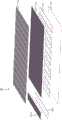
图1是根据至少第一示出的实施例的有效平面相控阵列天线组件的分解等距视图。1 is an exploded isometric view of an active planar phased array antenna assembly in accordance with at least a first illustrated embodiment.
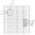
图2是图1的有效平面相控阵列天线组件的第一面板的部分的前视平面图。FIG. 2 is a front plan view of a portion of a first panel of the active planar phased array antenna assembly of FIG. 1 .
图3是图1的有效平面相控阵列天线组件的微波子阵列的等距视图。3 is an isometric view of a microwave subarray of the active planar phased array antenna assembly of FIG. 1 .
图4是图3的微波子阵列的分解等距视图。FIG. 4 is an exploded isometric view of the microwave subarray of FIG. 3 .
图5是移除了顶部面板的图3的微波子阵列的前视平面图的特写。5 is a close-up of a front plan view of the microwave subarray of FIG. 3 with the top panel removed.
图6是移除了侧面以显示L波段腔的图3的微波子阵列的特写的等距局部视图。6 is an isometric partial view of a close-up of the microwave subarray of FIG. 3 with the sides removed to show the L-band cavity.
图7是示出L波段馈电网络的L波段辐射元件的横截面视图。7 is a cross-sectional view showing an L-band radiating element of an L-band feed network.
图8是示出X波段馈电网络的X波段辐射元件的横截面视图。8 is a cross-sectional view showing an X-band radiating element of an X-band feed network.
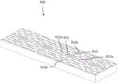
图9是根据至少第二示出的实施例的有效平面相控阵列天线组件的微波子阵列的等距视图。9 is an isometric view of a microwave subarray of an active planar phased array antenna assembly in accordance with at least a second illustrated embodiment.
图10是图9的微波子阵列的分解等距视图。FIG. 10 is an exploded isometric view of the microwave subarray of FIG. 9 .
图11是移除侧面以显示L波段腔的图9的微波子阵列的特写的等距局部视图。11 is an isometric partial view of a close-up of the microwave subarray of FIG. 9 with the sides removed to show the L-band cavity.
图12是示出图9的有效平面相控阵列天线组件的L波段辐射元件的增益的极坐标图。FIG. 12 is a polar plot showing the gain of the L-band radiating elements of the effective planar phased array antenna assembly of FIG. 9 .
图13是示出图9的有效平面相控阵列天线组件的X波段辐射元件的增益的极坐标图。FIG. 13 is a polar plot showing the gain of the X-band radiating elements of the effective planar phased array antenna assembly of FIG. 9 .
图14是示出图9的有效平面相控阵列天线组件的L波段辐射元件的阻抗史密斯圆图。FIG. 14 is a Smith chart showing the impedance of the L-band radiating elements of the effective planar phased array antenna assembly of FIG. 9 .
具体实施方式Detailed ways
除上下文另有要求之外,在说明书和权利要求书中,采用的词语“包括”及其变型应被解释为开放的包括的意义,即“包括但不限于”。In the specification and claims, the use of the word "comprising" and variations thereof should be construed in an open inclusive sense, ie, "including but not limited to", unless the context otherwise requires.
在该说明书中引用的“一个实施例”或“实施例”意味着结合实施例描述的特定特性、结构或特征被包括在至少一个实施例中。因此,在该说明书中的各处出现的短语“在一个实施例中”或“在实施例中”不一定都指的是相同的实施例。此外,特定特性、结构或特征可以以任何合适的方式在一个或更多个实施例组合。Reference in this specification to "one embodiment" or "an embodiment" means that a particular feature, structure or characteristic described in connection with the embodiment is included in at least one embodiment. Thus, appearances of the phrases "in one embodiment" or "in an embodiment" in various places in this specification are not necessarily all referring to the same embodiment. Furthermore, the particular features, structures or characteristics may be combined in any suitable manner in one or more embodiments.
如在该说明书和所附权利要求中所使用的,除内容明确指定之外,单数形式“一个”和“该/所述”包括复数指示物。还应该注意,除内容明确指定之外,术语“或”通常以其最广泛的意义使用,即意味着“和/或”。As used in this specification and the appended claims, the singular forms "a" and "the/said" include plural referents unless the content clearly dictates otherwise. It should also be noted that the term "or" is generally employed in its broadest sense, ie, meaning "and/or", unless the content clearly dictates otherwise.
这里提供的公开的摘要仅仅是为了方便,并不解释实施例的范围或含义。The abstract of the disclosure provided herein is for convenience only and does not interpret the scope or meaning of the embodiments.
在传统的天线组件中,辐射元件通常安装在结构子组件(诸如铝蜂窝板)上。该结构组件在不增强电磁性能的情况下,有助于天线组件的整体质量和体积。In conventional antenna assemblies, radiating elements are typically mounted on structural subassemblies such as aluminum honeycomb panels. The structural assembly contributes to the overall mass and volume of the antenna assembly without enhancing electromagnetic performance.
辐射元件通常不是自支撑的并且被安装到结构子组件。辐射元件通常包括电介质材料,其与用于将辐射元件附接到结构子组件的电介质材料结合能够导致重大的天线损失。Radiating elements are generally not self-supporting and are mounted to structural subassemblies. The radiating element typically includes a dielectric material that, in combination with the dielectric material used to attach the radiating element to the structural subassembly, can result in significant antenna losses.
使用传统技术,能够使用贴片元件来实现多频天线。这样的贴片元件有时被分层或堆叠,并且被穿孔以允许较小的辐射元件辐射通过较大的辐射元件,例如X波段辐射元件辐射通过L波段辐射元件。Using conventional techniques, a multi-frequency antenna can be implemented using patch elements. Such patch elements are sometimes layered or stacked, and perforated to allow smaller radiating elements to radiate through larger radiating elements, eg, X-band radiating elements to radiate through L-band radiating elements.
在本方法中,微波结构包括一个或更多个子阵列中的辐射元件,并且不要求单独的结构子组件。微波子阵列能够是自支撑的并且被配置为使得微波子阵列的辐射元件也用作结构元件。In the present method, the microwave structure includes radiating elements in one or more subarrays, and no separate structure subassembly is required. The microwave sub-array can be self-supporting and configured such that the radiating elements of the microwave sub-array also serve as structural elements.
此外,能够布置多频天线组件来将两个波段(诸如X波段和L波段)的辐射元件集成到共同的孔中。例如,能够在L波段槽之间的空间中放置X波段槽或贴片辐射元件。Furthermore, multi-frequency antenna assemblies can be arranged to integrate radiating elements of two bands, such as X-band and L-band, into a common aperture. For example, X-band slots or patch radiating elements can be placed in the spaces between the L-band slots.
图1示出了根据至少第一示出的实施例的有效平面相控阵列天线组件100。天线组件100的大小能够被定制以满足特定应用的增益和带宽要求。一个示例应用是双波段双极化SAR天线。在双波段双极化SAR天线的示例实施方式中,组件100大约2.15m宽、1.55m长和50mm深,并且重约30kg。Figure 1 shows an active planar phased
天线组件100是双波段(X波段和L波段)、双极化(在L波段的H和V极化)SAR天线组件的示例。虽然本文中描述的实施例涉及双X波段和L波段SAR天线,并且由于本文中其他地方描述的理由,该技术特别适用于基于空间的SAR天线,但是针对包括但不限于不同频率的单波段和多波段SAR天线以及微波和毫米波通信天线的其他频率、极化、配置和应用,也能够采用类似的方法。
天线组件100包括在天线组件100的顶部表面上的第一面板110,其包含用于L波段和X波段辐射元件(在随后的图中详细示出)的槽。
天线组件100包括在第一面板110之下的微波结构120。微波结构120包括一个或更多个子阵列,诸如子阵列120-1,每个子阵列包括L波段和X波段辐射元件。以下更详细地描述辐射元件。The
微波结构120是金属结构,其是自支撑的并且不要求单独结构的子组件。微波结构120能够由一个或更多个金属块(诸如铝块或另一种合适的导电材料的块)加工或制造。针对微波结构120的材料的选择,至少部分地确定了天线的损耗并且因此确定了天线的效率。The
天线组件110包括在微波结构120之下的第二面板130,第二面板130在后面封闭一个或更多个L波段腔。以下参照图11更详细地描述L波段腔。
天线组件110包括在第二面板130之下的第三面板140,第三面板140包括波导终端。第三面板140还为天线组件110提供至少部分的结构支撑。The
在一些实施中,天线组件110包括在第三面板140之下的多层印刷电路板(printedcircuit board,PCB)(图1中未示出),PCB容纳用于X波段辐射元件和L波段辐射元件的全体馈电网络。In some implementations, the
图2是图1的有效平面相控阵列天线组件100的第一面板110的部分的平面视图1。第一面板110包括多个L波段辐射元件,诸如L波段辐射元件210。L波段辐射元件210包括L波段H极化槽212和L波段V极化槽214。FIG. 2 is a plan view 1 of a portion of the
第一面板110还包括多个X波段辐射元件,诸如X波段辐射元件220。X波段辐射元件220包括一个或更多个X波段波导。在图2所示的示例中,X波段元件包括四个X波段波导,诸如X波段波导220-1。X波段波导220-1包括多个X波段槽。在所示的示例中,X波段波导220-1包括六个槽,例如X波段槽220-1a和220-1b。X波段波导220-1还包括X波段馈电器225。The
X波段槽(诸如X波段槽220-1a和220-1b)的长度至少部分地确定了天线组件100的谐振频率。每个X波段槽(诸如X波段槽220-1a和220-1b)距X波段波导(诸如X波段波导220-1)的中心线的偏移至少部分地限定了辐射效率。The length of the X-band slots, such as the X-band slots 220-1a and 220-1b, at least in part determine the resonant frequency of the
由于属于相邻X波段波导的X波段槽沿与相应波导的中心线的相反方向偏移,所以馈电器被配置为彼此异相180°,使得从相邻波导发射的辐射是同相的。Since the X-band slots belonging to adjacent X-band waveguides are offset in the opposite direction from the centerline of the corresponding waveguide, the feeds are configured to be 180° out of phase with each other so that radiation emitted from adjacent waveguides is in-phase.
能够选择每个X波段元件之间以及每个L波段元件之间的间隔,以消除或者至少减少光栅瓣和扫描盲点(在一个或更多个扫描角度上的增益的损失)的影响。The spacing between each X-band element and between each L-band element can be chosen to eliminate or at least reduce the effects of grating lobes and scan blind spots (loss of gain over one or more scan angles).
图3是图1的有效平面相控阵列天线组件的微波子阵列300的等距视图。微波子阵列300包括分别用于L波段和X波段的辐射元件310和320。微波子阵列300还包括L波段和X波段馈电器和馈电外壳(图3中未示出)。FIG. 3 is an isometric view of the
L波段辐射元件具有用于水平极化和垂直极化的交叉槽以及背腔。如图6所示,在孔之后使用谐振腔,减小了开槽天线所需的深度。如下所述,交叉的L波段槽周围的体积能够用于X波段辐射元件。The L-band radiating element has crossed slots for horizontal and vertical polarization and a back cavity. As shown in Figure 6, the use of a resonant cavity after the hole reduces the depth required for the slotted antenna. As described below, the volume surrounding the intersecting L-band slots can be used for X-band radiating elements.
L波段辐射元件310包括L波段H极化槽312和L波段V极化槽314。X波段辐射元件320包括四个波导,每个波导包括多个槽,诸如320-1a和320-1b。The L-
在示例实施中,第一面板和腔之间的空间约为15mm厚。这足够厚以适应X波段波导从其宽尺寸辐射。X波段元件的波导实施是有吸引力的选择,因为它是低损耗的并且增加了天线的效率。In an example implementation, the space between the first panel and the cavity is about 15mm thick. This is thick enough to accommodate the X-band waveguide radiating from its wide dimensions. A waveguide implementation of X-band elements is an attractive option because it is low loss and increases the efficiency of the antenna.
L波段槽之间的空间能够容纳多于一个的X波段波导辐射器。一个实施方式以更高的衰减和更低的功率处理能力为代价,使用脊形波导来增加带宽。脊形波导能够在中心被馈电。X波段辐射器能够通过探针激励或通过波导的环路耦合激励来馈电。The space between the L-band slots can accommodate more than one X-band waveguide radiator. One embodiment uses ridge waveguides to increase bandwidth at the expense of higher attenuation and lower power handling capability. Ridge waveguides can be fed centrally. X-band radiators can be fed by probe excitation or loop-coupled excitation through waveguides.
如图3所示,L波段交叉槽形成围绕X波段辐射单元的边界。在一个实施例中,两组四个X波段脊形波导能够安装在每对L波段交叉槽之间。在另一个实施例中,针对不同的增益要求,在每对L波段交叉槽之间放置单组四个X波段脊形波导。As shown in Figure 3, the L-band cross-groove forms a boundary around the X-band radiating element. In one embodiment, two sets of four X-band ridge waveguides can be installed between each pair of L-band crossing grooves. In another embodiment, a single set of four X-band ridge waveguides is placed between each pair of L-band cross-grooves for different gain requirements.
微波子阵列300还包括顶部面板330、侧板340、端板345和底部面板350。底部面板350是用于L波段辐射元件的接地平面和反射器。微波子阵列300的厚度d与频率有关。厚度d对应于L波段腔的深度(图6中示出),并且对于开槽天线而言,通常是λ/4,其中,λ是L波段波长。如下更详细描述的,通过使用折叠的L波段腔,微波子阵列300的厚度d能够小于λ/4。The
理想的开槽天线是λ/4深,并且包括槽,该槽不是具有通向关联的腔的开口的槽。在L波段波长处,槽的深度(其决定了天线组件的厚度)大约会为6cm。希望减小天线组件的厚度、为馈电器和电子器件留出空间以及满足对天线尺寸(诸如运载火箭尺寸所应用的天线尺寸)的要求。An ideal slotted antenna is λ/4 deep and includes a slot that is not a slot with an opening to the associated cavity. At L-band wavelengths, the depth of the slot, which determines the thickness of the antenna assembly, will be approximately 6 cm. It is desirable to reduce the thickness of the antenna assembly, to make room for the feed and electronics, and to meet requirements for antenna dimensions such as those applied to launch vehicle dimensions.
简单地减小L波段槽的深度会导致难以匹配的天线。由于馈电器附近和辐射槽附近的导电壁的存在,天线具有低阻抗。Simply reducing the depth of the L-band slot results in an antenna that is difficult to match. The antenna has low impedance due to the presence of conductive walls near the feeder and near the radiating slot.
在本申请中描述的技术包括孔后面的谐振腔。从概念上讲,每个L波段槽首先被分叉,然后每个分叉逐渐转向侧边,以使得形成“T”。“T”的交叉件位于由L波段辐射元件占据的天线子组件顶部面板的区域之下。在实施中,每个L波段槽通向L波段腔(如图6所示)。The technology described in this application includes a resonant cavity behind the hole. Conceptually, each L-band slot is first bifurcated, and then each bifurcation is gradually turned to the side so that a "T" is formed. The "T" crosspieces are located below the area of the top panel of the antenna subassembly occupied by the L-band radiating elements. In implementation, each L-band slot leads to an L-band cavity (as shown in Figure 6).
为了使槽有效地辐射,需要周围的导电表面来支撑电流。许多X波段辐射元件能够放置在L波段槽周围的微波子阵列的区域中。For the slot to radiate effectively, a surrounding conductive surface is required to support the current. A number of X-band radiating elements can be placed in the area of the microwave sub-array around the L-band slot.
在一个实施例中,L波段馈电器能够实施在放置在微波子阵列侧面的低损耗衬底材料中,其中探针穿过L波段槽。因为在这个实施例中,L波段馈电外壳沿着微波子阵列300的侧面,所以它们能够充当用于微波子阵列的加强件。In one embodiment, the L-band feed can be implemented in a low-loss substrate material placed on the side of the microwave sub-array, with the probe passing through the L-band slot. Because the L-band feed housings are along the sides of the
在另一个实施例中,L波段馈电器能够使用槽和腔之间的带线来实现。这在下面更详细地描述。In another embodiment, the L-band feed can be implemented using a stripline between the slot and the cavity. This is described in more detail below.
微波子阵列的数量,针对其预期目的,被选择为实现所期望的增益、覆盖范围以及目标分辨率。The number of microwave sub-arrays, for their intended purpose, is selected to achieve the desired gain, coverage, and target resolution.
图4是图3的微波子阵列300的分解视图。微波子阵列300包括顶部面板330、侧板340、端板345和底部面板350。底部面板350覆盖L波段腔的底部并且包括用于X波段馈电器的槽355。FIG. 4 is an exploded view of the
微波子阵列300分别包括L波段H极化槽312和L波段V极化槽314。微波子阵列包括X波段波导,诸如波导320-1。在一些实施例中(诸如图4所示的实施例),波导320-1是脊形波导。The
图5是去除顶部面板330的图3的微波子阵列300的平面视图的特写。微波子阵列300分别包括L波段H极化槽312和L波段V极化槽314。微波子阵列包括X波段波导,诸如脊形波导320-1。微波子阵列300还包括多个X波段馈电器,诸如X波段馈电器325。参照图8更详细地描述X波段馈电器325。5 is a close-up of a plan view of the
图6是去除侧板340以示出L波段腔的图3的微波子阵列300的特写的等距局部视图。6 is an isometric partial view of a close-up of the
L波段腔610的尺寸与频率有关。L波段腔610的深度被选择为提供高的辐射效率,同时保持紧凑的尺寸。类似地,X波段波导(诸如X波段波导320-1)的尺寸至少部分地确定了谐振频率和带宽。X波段波导320-1包括脊620。The size of the L-
图7是示出了L波段馈电网络710的L波段辐射元件700的横截面图。L波段辐射元件700包括L波段槽720、腔730和反射器740。L波段馈电网络710包括带线712、探针714和接地平面716。FIG. 7 is a cross-sectional view illustrating the L-
L波段馈电网络710包括嵌入在带线712中的匹配网络(图7中未示出),以促进跨带宽的阻抗的匹配。The L-
L波段槽720包括彼此异相180°的两个探针。槽720中两个探针的位置被选择为实现所期望的辐射效率。H极化L波段槽和V极化L波段槽能够被独立馈电。能够同时传输H极化脉冲和V极化脉冲。The L-
带线712以穿过槽720的探针714结束,可操作该探针以激励槽720中的场。The
L波段馈电网络710能够包括屏蔽(图7中未示出)以抑制交叉极化。在示例性实施方式中,L波段馈电网络被配置为抑制交叉极化60dB。The L-
图8是示出X波段馈电网络820的X波段辐射元件800的横截面图。X波段辐射元件800包括四个波导810a、810b、810c和810d。波导810a、810b、810c和810d是脊形波导并且在波导内具有脊。脊的尺寸至少部分地确定了功率输送、匹配和带宽。波导中脊的益处是对于等效辐射效率具有更高的增益。包括脊的波导能够小于没有脊的等效波导,并且能够将更多的脊波导封装到等效体积中。FIG. 8 is a cross-sectional view illustrating an
X波段馈电网络820包括四个同轴电缆820a、820b、820c和820d,波导810a、810b、810c和810d中的每个波导针对四个同轴电缆820a、820b、820c和820d中的一个。每个波导由其相应的同轴电缆馈电,电缆的内部导体(图8中未示出)穿过脊中的孔以与波导的顶壁接触。The X-band feed network 820 includes four
馈电同轴电缆被通信地耦接以向辐射槽馈送产生定向光束所需的振幅和相位信号,并执行光束扫描。在图8中所示的示例中,两根相邻的同轴电缆异相180°。A feed coaxial cable is communicatively coupled to feed the radiation slot with the amplitude and phase signals required to generate the directional beam and to perform beam scanning. In the example shown in Figure 8, two adjacent coaxial cables are 180° out of phase.
图9是有效平面相控阵列天线组件的第二实施例的微波子阵列900的等距视图。微波子阵列900包括分别用于H极化和V极化的交叉的L波段槽对,诸如槽910和915。在平面视图中,在图2至图7中,L波段槽(诸如槽310和315)具有矩形形状。在图9中所示的实施例中,槽910和915分别具有圆形端部910a和910b以及915a和915b。9 is an isometric view of a
尽管图9示出了圆形的端部,但其他合适的形状能够用于槽端部。此外,每个槽的部分或全部长度能够被成形或逐渐变小,例如通过从中间朝向每个端部提供每个槽的线性或指数的逐渐变小。成形的槽的益处是改善了谐振频率的调谐和增加了带宽。Although Figure 9 shows rounded ends, other suitable shapes can be used for the slot ends. Furthermore, part or all of the length of each groove can be shaped or tapered, for example by providing a linear or exponential taper of each groove from the middle towards each end. The benefits of a shaped slot are improved tuning of the resonant frequency and increased bandwidth.
通过展开L波段槽的垂直壁能够获得类似的好处。L波段槽的横截面轮廓能够被成形为实现所期望的谐振频率和带宽。在一种实施方式中,L波段槽的侧面是垂直的。在另一种实施方式中,L波段槽的侧面以线性方式从槽的顶部到槽的底部逐渐变小。在又一种实施方式中,L波段槽的侧面根据指数曲线的一部分从槽的顶部到槽的底部逐渐变小。在其他实施方式中,能够使用其他合适的逐渐变小方式。Similar benefits can be obtained by unfolding the vertical walls of the L-band slot. The cross-sectional profile of the L-band slot can be shaped to achieve the desired resonant frequency and bandwidth. In one embodiment, the sides of the L-band slot are vertical. In another embodiment, the sides of the L-band groove taper in a linear fashion from the top of the groove to the bottom of the groove. In yet another embodiment, the sides of the L-band groove taper from the top of the groove to the bottom of the groove according to a portion of an exponential curve. In other embodiments, other suitable tapering approaches can be used.
在一些实施方式中,槽和其横截面轮廓的成形被组合以实现所期望的频率和带宽。In some embodiments, the shaping of the slot and its cross-sectional profile is combined to achieve the desired frequency and bandwidth.
能够用材料(例如低损耗电介质)部分地或完全地填充L波段槽,以调节槽的电长度,从而在不改变槽的物理长度的情况下,实现所期望的谐振频率。The L-band slot can be partially or fully filled with material (eg, a low loss dielectric) to adjust the electrical length of the slot to achieve the desired resonant frequency without changing the physical length of the slot.
图10是图9的微波子阵列的分解视图。FIG. 10 is an exploded view of the microwave subarray of FIG. 9 .
图11是去除侧面以显示L波段腔的图9的微波子阵列的特写的等距局部视图。11 is an isometric partial view of a close-up of the microwave subarray of FIG. 9 with the sides removed to show the L-band cavity.
图12是示出图9的有效平面相控阵列天线组件的L波段辐射元件的增益的极坐标图。在所示的示例中,在整个仰角范围内,实现了至少60dB的共极化到交叉极化隔离率。圆1210指示针对三个频率的共极化增益图。圆1220指示针对相同的三个频率的交叉极化增益图。FIG. 12 is a polar plot showing the gain of the L-band radiating elements of the effective planar phased array antenna assembly of FIG. 9 . In the example shown, a co-polar to cross-polar isolation ratio of at least 60 dB is achieved over the entire elevation range.
图13是示出图9的有效平面相控阵列天线组件的X波段辐射元件的增益的极坐标图。在所示的示例中,实现至少18dB的峰值增益。FIG. 13 is a polar plot showing the gain of the X-band radiating elements of the effective planar phased array antenna assembly of FIG. 9 . In the example shown, a peak gain of at least 18 dB is achieved.
图14是针对图9的有效平面相控阵列天线组件的L波段辐射元件的阻抗史密斯圆图。FIG. 14 is an impedance Smith chart for the L-band radiating element of the effective planar phased array antenna assembly of FIG. 9 .
以上描述的天线技术的益处包括更大的质量效率和更大的辐射效率。仿真已经表明,X波段辐射单元和L波段辐射单元在频段内的辐射效率能够达到80%以上,包括所有的损耗。The benefits of the antenna technology described above include greater mass efficiency and greater radiation efficiency. Simulations have shown that the radiation efficiency of the X-band radiating element and the L-band radiating element in the frequency band can reach more than 80%, including all losses.
具有自支撑的天线的辐射元件使设计质量有效。不需要额外的结构质量。天线中的所有金属对天线执行两个功能—第一为辐射元件提供槽和腔,第二提供结构完整性。由于天线能够完全由金属构成,因此不存在有助于天线中损耗的电介质材料,并且天线的辐射效率高。唯一的损耗是表面金属损耗。A radiating element with a self-supporting antenna enables the design quality to be effective. No additional structural mass is required. All metal in the antenna performs two functions for the antenna - the first to provide a slot and cavity for the radiating element, and the second to provide structural integrity. Since the antenna can be constructed entirely of metal, there are no dielectric materials that contribute to losses in the antenna, and the radiation efficiency of the antenna is high. The only loss is surface metal loss.
所示实施例的以上描述(包括在摘要中描述的内容)不旨在是穷举或将各种实施例限制为所公开的精确形式。如本领域技术人员将认识到的,为了阐明目的,尽管在本文中描述了具体实施例和示例,但是在不脱离本公开的精神和范围的情况下,能够进行各种等同修改。本文提供的各种实施例的教导能够应用于其他成像系统,不一定是上面通常描述的示例性卫星成像系统。The above description of illustrated embodiments, including what is described in the Abstract, is not intended to be exhaustive or to limit the various embodiments to the precise forms disclosed. As those skilled in the art will recognize, although specific embodiments of, and examples for, are described herein for illustrative purposes, various equivalent modifications can be made without departing from the spirit and scope of the present disclosure. The teachings of the various embodiments provided herein can be applied to other imaging systems, not necessarily the exemplary satellite imaging systems generally described above.
虽然以上描述大部分涉及用于SAR和光学传感器的卫星平台,但是能够使用包括但不限于飞机和无人机的机载传感器来获取遥感图像。本公开中描述的技术能够用于从星载和机载平台上的传感器获取的图像。While much of the above description refers to satellite platforms for SAR and optical sensors, remote sensing imagery can be acquired using airborne sensors including, but not limited to, aircraft and drones. The techniques described in this disclosure can be used with images acquired from sensors on spaceborne and airborne platforms.
以上描述的各种实施例能够被组合以提供其他实施例。2015年3月25日提交的美国临时专利申请62/137,934(代理案号920140.404P1);2015年6月16日提交的名称为“有效平面相控阵列天线组件”(代理案号920140.405P1)的美国临时专利申请62/180,421;2015年6月16日提交的名称为“用于增强合成孔径雷达成像的系统和方法”的美国临时专利申请62/180,449(代理案号920140.407P1);以及2015年6月16日提交的名称为“用于从空间远程感测地球的系统和方法”(代理案卷号920140.406P1)的美国临时专利申请62/180,440,各自通过引用全部并入本文。如有必要,能够修改实施例的方面以采用各种专利、应用和出版物的系统、电路和概念来提供其他实施例。The various embodiments described above can be combined to provide other embodiments. U.S. Provisional Patent Application 62/137,934, filed March 25, 2015 (Attorney Docket No. 920140.404P1); U.S. Provisional Patent Application 62/180,421; U.S. Provisional Patent Application 62/180,449 (Attorney Docket No. 920140.407P1), filed June 16, 2015, entitled "Systems and Methods for Enhanced Synthetic Aperture Radar Imaging"; and 2015 US Provisional Patent Application 62/180,440, filed June 16, entitled "SYSTEMS AND METHODS FOR REMOTE SENSING OF THE EARTH FROM SPACE" (Attorney Docket No. 920140.406P1), each of which is incorporated herein by reference in its entirety. Aspects of the embodiments can be modified, if necessary, to provide other embodiments using the systems, circuits, and concepts of various patents, applications, and publications.
例如,前面的详细描述已经通过使用框图、示意图和示例阐述了装置和/或过程的各种实施例。在这种框图、示意图和示例包含一个或更多个功能和/或操作的范围内,本领域技术人员应该理解,通过各种不同的硬件、软件、固件或者几乎它们的任何组合,能够单独地和/或共同地实现这种框图、流程图或示例中的每个功能和/或操作。在一个实施例中,本主题可以通过专用集成电路(ASIC)来实现。然而,本领域技术人员将认识到,本文所公开的实施例能够全部或部分地在标准集成电路中等效地实现为在一个或更多个计算机上运行的一个或更多个计算机程序(例如,实现为在一个或更多个计算机系统上运行的一个或更多个程序)、实现为在一个或更多个控制器(例如微控制器)上运行的一个或更多个程序、实现为在一个或更多个处理器(例如微处理器)上运行的一个或更多个程序、实现为固件或者实现为几乎它们的任何组合,并且根据本公开内容,为软件和/或固件设计电路和/或编写代码,完全在本领域普通技术人员的技能内。For example, the foregoing detailed description has set forth various embodiments of apparatuses and/or processes through the use of block diagrams, schematic diagrams, and examples. To the extent that such block diagrams, schematic diagrams, and examples include one or more functions and/or operations, those skilled in the art will appreciate that through a variety of different hardware, software, firmware, or virtually any combination thereof, the and/or collectively implement each function and/or operation in such block diagrams, flowcharts or examples. In one embodiment, the present subject matter may be implemented by an application specific integrated circuit (ASIC). Those skilled in the art will recognize, however, that the embodiments disclosed herein can be equivalently implemented, in whole or in part, in standard integrated circuits as one or more computer programs running on one or more computers (eg, implemented as one or more programs running on one or more computer systems), implemented as one or more programs running on one or more controllers (eg, microcontrollers), implemented as One or more programs running on one or more processors (eg, microprocessors), implemented as firmware, or almost any combination thereof, and in accordance with the present disclosure, design circuits and/or software and/or firmware and/or writing code, is well within the skill of one of ordinary skill in the art.
另外,本领域的技术人员将认识到,本文教导的机构能够以各种形式作为程序产品来发布,并且不管用于实际执行分布的信号承载介质的特定类型如何,说明性实施例同样适用。信号承载介质的示例包括但不限于以下:可记录类介质,诸如软盘、硬盘驱动器,CDROM、数字磁带和计算机存储器;以及诸如使用基于TDM或IP的通信链路(例如数据包链路)的数字和模拟通信链路的传输类介质。Additionally, those skilled in the art will recognize that the mechanisms taught herein can be distributed in various forms as program products, and that the illustrative embodiments are equally applicable regardless of the particular type of signal bearing medium used to actually perform the distribution. Examples of signal bearing media include, but are not limited to, the following: recordable-type media such as floppy disks, hard drives, CDROMs, digital tapes, and computer memory; and digital media such as those using TDM or IP-based communication links (eg, packet links) and transmission-like media that simulate communication links.
根据以上详细描述能够做出这些和其他变型。通常,在所述权利要求中,所使用的术语不应该被解释为将本发明限制在说明书和权利要求书中公开的特定实施例,而应该被解释为包括所有可能的实施例以及权利要求的等同物的全部范围。因此,本发明不受本公开的限制。These and other modifications can be made in light of the above detailed description. In general, the terms used in the claims should not be construed to limit the invention to the specific embodiments disclosed in the specification and claims, but should be construed to include all possible embodiments and the scope of the claims. the full range of equivalents. Therefore, the present invention is not limited by the present disclosure.
Claims (26)
Translated fromChineseApplications Claiming Priority (3)
| Application Number | Priority Date | Filing Date | Title |
|---|---|---|---|
| US201562180421P | 2015-06-16 | 2015-06-16 | |
| US62/180,421 | 2015-06-16 | ||
| PCT/US2016/037666WO2017044168A2 (en) | 2015-06-16 | 2016-06-15 | Efficient planar phased array antenna assembly |
Publications (2)
| Publication Number | Publication Date |
|---|---|
| CN108432049A CN108432049A (en) | 2018-08-21 |
| CN108432049Btrue CN108432049B (en) | 2020-12-29 |
Family
ID=58239686
Family Applications (1)
| Application Number | Title | Priority Date | Filing Date |
|---|---|---|---|
| CN201680045476.4AExpired - Fee RelatedCN108432049B (en) | 2015-06-16 | 2016-06-15 | Effective Planar Phased Array Antenna Assemblies |
Country Status (5)
| Country | Link |
|---|---|
| US (1) | US10615513B2 (en) |
| EP (1) | EP3311449B1 (en) |
| CN (1) | CN108432049B (en) |
| CA (1) | CA2990063A1 (en) |
| WO (1) | WO2017044168A2 (en) |
Families Citing this family (20)
| Publication number | Priority date | Publication date | Assignee | Title |
|---|---|---|---|---|
| WO2016153914A1 (en) | 2015-03-25 | 2016-09-29 | King Abdulaziz City Of Science And Technology | Apparatus and methods for synthetic aperture radar with digital beamforming |
| CA3044806A1 (en) | 2015-11-25 | 2017-06-01 | Urthecast Corp. | Synthetic aperture radar imaging apparatus and methods |
| CN106526572A (en)* | 2016-11-07 | 2017-03-22 | 深圳市速腾聚创科技有限公司 | One-dimensional phased array radar and one-dimensional phased array radar control method |
| CA3064735C (en) | 2017-05-23 | 2022-06-21 | Urthecast Corp. | Synthetic aperture radar imaging apparatus and methods |
| US11378682B2 (en) | 2017-05-23 | 2022-07-05 | Spacealpha Insights Corp. | Synthetic aperture radar imaging apparatus and methods for moving targets |
| CA3083033A1 (en) | 2017-11-22 | 2019-11-28 | Urthecast Corp. | Synthetic aperture radar apparatus and methods |
| EP3724951A4 (en)* | 2018-02-09 | 2021-08-18 | AVX Corporation | TUBULAR PHASE CONTROLLED GROUP ANTENNA |
| EP3724950A4 (en)* | 2018-02-09 | 2021-08-25 | AVX Corporation | DOME PHASED ANTENNA |
| US10468780B1 (en)* | 2018-08-27 | 2019-11-05 | Thinkom Solutions, Inc. | Dual-polarized fractal antenna feed architecture employing orthogonal parallel-plate modes |
| CN110112580B (en)* | 2019-05-10 | 2021-02-05 | 电子科技大学 | A circular waveguide dual-frequency common aperture antenna based on structure multiplexing |
| CN109755763B (en)* | 2019-01-31 | 2021-01-01 | 西南电子技术研究所(中国电子科技集团公司第十研究所) | S/Ku dual-frequency common-caliber linear polarization phased array scanning antenna |
| CN111771304A (en)* | 2019-03-29 | 2020-10-13 | 深圳市大疆创新科技有限公司 | False antenna structure and millimeter wave antenna array |
| CN110380201A (en)* | 2019-07-01 | 2019-10-25 | 中国航空工业集团公司雷华电子技术研究所 | A kind of X and ka two waveband is total to mouth face micro-strip array antenna |
| CN110426699A (en)* | 2019-07-31 | 2019-11-08 | 中国科学院上海微系统与信息技术研究所 | A kind of front end system and preparation method thereof of plate two-band detector |
| US11437732B2 (en)* | 2019-09-17 | 2022-09-06 | Raytheon Company | Modular and stackable antenna array |
| CN111029717B (en)* | 2019-12-29 | 2021-01-05 | 南京屹信航天科技有限公司 | Ku-waveband double-frequency microstrip array antenna |
| CN111180900B (en)* | 2019-12-31 | 2021-01-15 | 中国科学院电子学研究所 | Multiband airborne radar antenna |
| CN111799561B (en)* | 2020-08-04 | 2021-10-29 | 西安电子科技大学 | Slot L-shaped antenna based on improved "H"-shaped waveguide and its array |
| CN115036679B (en)* | 2022-07-14 | 2023-10-20 | 西安航天天绘数据技术有限公司 | Flat-panel antenna that many subarrays were assembled |
| CN115441196B (en)* | 2022-09-23 | 2025-03-18 | 中国科学院空天信息创新研究院 | Dual-band coplanar waveguide slot antenna |
Citations (7)
| Publication number | Priority date | Publication date | Assignee | Title |
|---|---|---|---|---|
| US3193830A (en)* | 1963-07-25 | 1965-07-06 | Joseph H Provencher | Multifrequency dual ridge waveguide slot antenna |
| US20020003502A1 (en)* | 2000-07-10 | 2002-01-10 | Falk Kent Olof | One aperture simultaneous RX-TX-antenna |
| US20040104859A1 (en)* | 2002-12-02 | 2004-06-03 | Zane Lo | Wide bandwidth flat panel antenna array |
| CN102394379A (en)* | 2011-06-21 | 2012-03-28 | 中国兵器工业第二○六研究所 | Dual-band co-aperture flat array antenna |
| CN102983410A (en)* | 2012-11-09 | 2013-03-20 | 深圳光启创新技术有限公司 | Reflective array face and reflective array antenna |
| CN103414027A (en)* | 2013-07-18 | 2013-11-27 | 北京遥测技术研究所 | Wide band single pulse flat plate slot array antenna |
| CN104201469A (en)* | 2014-08-29 | 2014-12-10 | 华为技术有限公司 | Antenna and communication device |
Family Cites Families (424)
| Publication number | Priority date | Publication date | Assignee | Title |
|---|---|---|---|---|
| US3241140A (en) | 1962-09-21 | 1966-03-15 | Litton Systems Inc | Method and means for eliminating radar range ambiguities |
| US3460139A (en) | 1967-09-06 | 1969-08-05 | Us Army | Communication by radar beams |
| US3601529A (en) | 1968-11-20 | 1971-08-24 | Rca Corp | Color television signal-generating apparatus |
| US3715962A (en) | 1970-04-20 | 1973-02-13 | Spectral Data Corp | Spectral-zonal color reconnaissance system |
| GB1413122A (en) | 1971-12-18 | 1975-11-05 | Victor Company Of Japan | Colour television signal generating apparatus |
| DE2619027C2 (en) | 1976-04-30 | 1984-10-18 | Robert Bosch Gmbh, 7000 Stuttgart | Television recording system |
| US5646623A (en) | 1978-05-15 | 1997-07-08 | Walters; Glenn A. | Coherent, frequency multiplexed radar |
| DE2850309C2 (en) | 1978-11-20 | 1987-05-14 | Robert Bosch Gmbh, 7000 Stuttgart | Colour television recording system |
| US4214264A (en) | 1979-02-28 | 1980-07-22 | Eastman Kodak Company | Hybrid color image sensing array |
| JPS56108976A (en) | 1980-02-01 | 1981-08-28 | Mitsubishi Electric Corp | Signal processing system of synthetic aperture radar |
| US4404586A (en) | 1981-12-15 | 1983-09-13 | Fuji Photo Film Co., Ltd. | Solid-state color imager with stripe or mosaic filters |
| US4514755A (en) | 1983-07-08 | 1985-04-30 | Fuji Photo Film Co., Ltd. | Solid-state color imager with two layer three story structure |
| JPS60257380A (en) | 1984-06-02 | 1985-12-19 | Natl Space Dev Agency Japan<Nasda> | Image processing method of synthetic aperture radar |
| JPH0820230B2 (en) | 1984-06-08 | 1996-03-04 | オリンパス光学工業株式会社 | Measuring endoscope |
| JPH0619243B2 (en) | 1985-09-19 | 1994-03-16 | 株式会社トプコン | Coordinate measuring method and apparatus thereof |
| JP2849813B2 (en) | 1986-12-19 | 1999-01-27 | 富士写真フイルム株式会社 | Video signal forming device |
| EP0316524B1 (en) | 1987-11-18 | 1993-04-21 | Siemens-Albis Aktiengesellschaft | Pulse radar system |
| DE3802219A1 (en) | 1988-01-26 | 1989-08-03 | Deutsche Forsch Luft Raumfahrt | METHOD AND DEVICE FOR REMOTE DETECTION OF THE EARTH |
| US5173949A (en) | 1988-08-29 | 1992-12-22 | Raytheon Company | Confirmed boundary pattern matching |
| JPH0727021B2 (en) | 1989-02-10 | 1995-03-29 | 三菱電機株式会社 | Synthetic aperture radar device |
| US4924229A (en) | 1989-09-14 | 1990-05-08 | The United States Of America As Represented By The United States Department Of Energy | Phase correction system for automatic focusing of synthetic aperture radar |
| CN1034126C (en)* | 1990-03-15 | 1997-02-26 | 中国科学院化学研究所 | Gutta-percha sealing material for wave-guide antenna of airborne radar |
| US5057843A (en) | 1990-06-25 | 1991-10-15 | The United States Of America As Represented By The Administrator Of The National Aeronautics And Space Administration | Method for providing a polarization filter for processing synthetic aperture radar image data |
| US5248979A (en) | 1991-11-29 | 1993-09-28 | Trw Inc. | Dual function satellite imaging and communication system using solid state mass data storage |
| DE4216828C2 (en) | 1992-05-21 | 1994-08-18 | Dornier Gmbh | Earth observation procedures |
| US5313210A (en) | 1993-02-23 | 1994-05-17 | Ball Corporation | Polarimetric radar signal mapping process |
| US6366244B1 (en)* | 1993-03-11 | 2002-04-02 | Southern California Edison Company | Planar dual band microstrip or slotted waveguide array antenna for all weather applications |
| DE4332590C2 (en) | 1993-09-24 | 1996-10-24 | Deutsche Forsch Luft Raumfahrt | Airborne SAR system for determining a terrain topography |
| JP2618332B2 (en) | 1994-03-08 | 1997-06-11 | 宇宙開発事業団 | Image quality evaluation method for synthetic aperture radar images |
| US5486830A (en) | 1994-04-06 | 1996-01-23 | The United States Of America As Represented By The United States Department Of Energy | Radar transponder apparatus and signal processing technique |
| US6865477B2 (en) | 1994-05-31 | 2005-03-08 | Winged Systems Corporation | High resolution autonomous precision positioning system |
| US5546091A (en) | 1994-11-23 | 1996-08-13 | Hughes Aircraft Company | Psuedo-color display for enhanced visual target detection |
| DE19620682C2 (en) | 1995-05-24 | 2001-06-28 | Deutsch Zentr Luft & Raumfahrt | Method for locating and identifying objects using a coded transponder |
| US5790188A (en) | 1995-09-07 | 1998-08-04 | Flight Landata, Inc. | Computer controlled, 3-CCD camera, airborne, variable interference filter imaging spectrometer system |
| US5552787A (en) | 1995-10-10 | 1996-09-03 | The United States Of America As Represented By The Secretary Of The Navy | Measurement of topography using polarimetric synthetic aperture radar (SAR) |
| US5760899A (en) | 1996-09-04 | 1998-06-02 | Erim International, Inc. | High-sensitivity multispectral sensor |
| US5745069A (en) | 1996-09-10 | 1998-04-28 | Ball Corporation | Reduction of radar antenna area |
| SE518543C2 (en) | 1996-12-04 | 2002-10-22 | Ericsson Telefon Ab L M | Method and apparatus for transmitting information in a pulse radar |
| US5973634A (en) | 1996-12-10 | 1999-10-26 | The Regents Of The University Of California | Method and apparatus for reducing range ambiguity in synthetic aperture radar |
| US5952971A (en) | 1997-02-27 | 1999-09-14 | Ems Technologies Canada, Ltd. | Polarimetric dual band radiating element for synthetic aperture radar |
| US5949914A (en) | 1997-03-17 | 1999-09-07 | Space Imaging Lp | Enhancing the resolution of multi-spectral image data with panchromatic image data using super resolution pan-sharpening |
| CA2201262C (en) | 1997-03-27 | 2006-06-13 | Cal Corporation | Synthetic aperture radar |
| JPH10341108A (en)* | 1997-04-10 | 1998-12-22 | Murata Mfg Co Ltd | Antenna system and radar module |
| EP1004151B1 (en)* | 1997-08-21 | 2006-12-13 | Kildal Antenn Consulting AB | Improved reflector antenna with a self-supported feed |
| US7198230B2 (en) | 1997-10-14 | 2007-04-03 | The Directv Group, Inc. | Method and system for maximizing satellite constellation coverage |
| US6007027A (en) | 1997-11-14 | 1999-12-28 | Motorola, Inc. | Method and apparatus for early service using phased satellite depolyment |
| DE19757309C1 (en) | 1997-12-22 | 1999-07-15 | Deutsch Zentr Luft & Raumfahrt | Process for processing Spotlight SAR raw data |
| CN1168178C (en)* | 1997-12-29 | 2004-09-22 | 钟信贤 | Low-cost high-performance portable phased array antenna system |
| US5945940A (en) | 1998-03-12 | 1999-08-31 | Massachusetts Institute Of Technology | Coherent ultra-wideband processing of sparse multi-sensor/multi-spectral radar measurements |
| US6122404A (en) | 1998-05-28 | 2000-09-19 | Trw Inc. | Visible stokes polarimetric imager |
| US6678048B1 (en) | 1998-07-20 | 2004-01-13 | Sandia Corporation | Information-efficient spectral imaging sensor with TDI |
| JP2000111359A (en) | 1998-10-05 | 2000-04-18 | Hitachi Ltd | Earth observation system |
| US6614813B1 (en) | 1999-01-28 | 2003-09-02 | Sandia Corporation | Multiplexed chirp waveform synthesizer |
| CA2365866C (en) | 1999-03-17 | 2007-07-24 | University Of Virginia Patent Foundation | Passive remote sensor of chemicals |
| US6259396B1 (en) | 1999-08-26 | 2001-07-10 | Raytheon Company | Target acquisition system and radon transform based method for target azimuth aspect estimation |
| SE517218C2 (en)* | 1999-09-03 | 2002-05-07 | Ericsson Telefon Ab L M | A low profile antenna structure and a device comprising wireless communication means, a wireless mobile terminal, a computer card suitable for insertion into an electronic device and a local network system comprising a base station and a plurality of terminals in wireless communication with the base station comprising such a low profile antenna structure |
| GB2354655A (en) | 1999-09-23 | 2001-03-28 | Matra Marconi Space Uk Ltd | Mitigation of Faraday rotation in space bourne radar |
| JP4020179B2 (en) | 1999-10-28 | 2007-12-12 | 三菱電機株式会社 | Satellite-mounted imaging device |
| US7019777B2 (en) | 2000-04-21 | 2006-03-28 | Flight Landata, Inc. | Multispectral imaging system with spatial resolution enhancement |
| AUPQ974100A0 (en) | 2000-08-28 | 2000-09-21 | Burns, Alan Robert | Real or near real time earth imaging system |
| US6700527B1 (en) | 2000-11-15 | 2004-03-02 | Harris Corporation | Coherent two-dimensional image formation by passive synthetic aperture collection and processing of multi-frequency radio signals scattered by cultural features of terrestrial region |
| US6741250B1 (en) | 2001-02-09 | 2004-05-25 | Be Here Corporation | Method and system for generation of multiple viewpoints into a scene viewed by motionless cameras and for presentation of a view path |
| ATE317549T1 (en) | 2001-03-15 | 2006-02-15 | SIDE VIEW RADAR SYSTEM WITH SYNTHETIC APERTURE | |
| CN1290226C (en)* | 2001-03-21 | 2006-12-13 | 株式会社脈克飞斯 | waveguide slot antenna |
| US6633253B2 (en) | 2001-04-02 | 2003-10-14 | Thomas J. Cataldo | Dual synthetic aperture radar system |
| US6347762B1 (en) | 2001-05-07 | 2002-02-19 | The United States Of America As Represented By The Secretary Of The Army | Multispectral-hyperspectral sensing system |
| JP3971900B2 (en)* | 2001-05-10 | 2007-09-05 | 日本放送協会 | Deployable active phased array antenna, transmitter and receiver |
| JP4115681B2 (en)* | 2001-05-10 | 2008-07-09 | 日本放送協会 | Active phased array antenna, two-dimensional planar active phased array antenna, transmitter and receiver |
| US7009163B2 (en) | 2001-06-22 | 2006-03-07 | Orbotech Ltd. | High-sensitivity optical scanning using memory integration |
| US6870501B2 (en) | 2001-06-26 | 2005-03-22 | Raytheon Company | Digital radio frequency tag |
| SE520249C2 (en) | 2001-07-02 | 2003-06-17 | Acreo Ab | Method for arranging a longitudinal solid body within a fiber |
| AUPR618401A0 (en) | 2001-07-06 | 2001-08-02 | Gecoz Pty Ltd | Method for determining soil salinity |
| US6970142B1 (en) | 2001-08-16 | 2005-11-29 | Raytheon Company | Antenna configurations for reduced radar complexity |
| US7149366B1 (en) | 2001-09-12 | 2006-12-12 | Flight Landata, Inc. | High-definition hyperspectral imaging system |
| GB0122226D0 (en)* | 2001-09-13 | 2001-11-07 | Koninl Philips Electronics Nv | Wireless terminal |
| US6577266B1 (en) | 2001-10-15 | 2003-06-10 | Sandia Corporation | Transponder data processing methods and systems |
| US7167280B2 (en) | 2001-10-29 | 2007-01-23 | Eastman Kodak Company | Full content film scanning on a film to data transfer device |
| JP2003149332A (en) | 2001-11-07 | 2003-05-21 | Communication Research Laboratory | Sea ice observation method |
| AUPR872901A0 (en) | 2001-11-09 | 2001-11-29 | Marine Research Wa Pty Ltd | Improved real or near real time earth imaging system |
| US6502790B1 (en) | 2001-11-20 | 2003-01-07 | Northrop Grumman Corporation | Inclined non-uniform planar spaced constellation of satellites |
| US7042386B2 (en) | 2001-12-11 | 2006-05-09 | Essex Corporation | Sub-aperture sidelobe and alias mitigation techniques |
| US6781707B2 (en) | 2002-03-22 | 2004-08-24 | Orasee Corp. | Multi-spectral display |
| GB0207052D0 (en)* | 2002-03-26 | 2002-05-08 | Antenova Ltd | Novel dielectric resonator antenna resonance modes |
| US6831688B2 (en) | 2002-04-08 | 2004-12-14 | Recon/Optical, Inc. | Multispectral or hyperspectral imaging system and method for tactical reconnaissance |
| US6680691B2 (en) | 2002-05-13 | 2004-01-20 | Honeywell International Inc. | Methods and apparatus for accurate phase detection |
| US20030210176A1 (en) | 2002-05-13 | 2003-11-13 | Hager James R. | Methods and apparatus for resolution of radar range ambiguities |
| US6714157B2 (en) | 2002-08-02 | 2004-03-30 | The Boeing Company | Multiple time-interleaved radar operation using a single radar at different angles |
| JP2004158911A (en)* | 2002-11-01 | 2004-06-03 | Murata Mfg Co Ltd | Sector antenna system and on-vehicle transmitter-receiver |
| FI115173B (en)* | 2002-12-31 | 2005-03-15 | Filtronic Lk Oy | Antenna for a collapsible radio |
| US6781540B1 (en) | 2003-02-21 | 2004-08-24 | Harris Corporation | Radar system having multi-platform, multi-frequency and multi-polarization features and related methods |
| US7292723B2 (en) | 2003-02-26 | 2007-11-06 | Walker Digital, Llc | System for image analysis in a network that is structured with multiple layers and differentially weighted neurons |
| US7218268B2 (en) | 2003-05-14 | 2007-05-15 | Veridian Systems | Self-calibrating interferometric synthetic aperture radar altimeter |
| DE10328279B3 (en) | 2003-06-23 | 2004-08-26 | Eads Deutschland Gmbh | Signal evaluation system for use in SAR/MTI pulse radar system, has transmit/receive antenna elements connected to delay channels, digital receivers and digital data stream generator |
| US6864827B1 (en) | 2003-10-15 | 2005-03-08 | Sandia Corporation | Digital intermediate frequency receiver module for use in airborne SAR applications |
| DE10356351A1 (en) | 2003-11-28 | 2005-06-30 | Deutsches Zentrum für Luft- und Raumfahrt e.V. | Interferometric microwave radar method |
| FR2864307A1 (en) | 2003-12-19 | 2005-06-24 | Thales Sa | DEVICE FOR DETECTING NON-METALLIC OBJECTS DISPOSED ON A HUMAN SUBJECT |
| US7599790B2 (en) | 2004-03-23 | 2009-10-06 | Google Inc. | Generating and serving tiles in a digital mapping system |
| WO2005104039A2 (en) | 2004-03-23 | 2005-11-03 | Google, Inc. | A digital mapping system |
| US7270299B1 (en) | 2004-03-23 | 2007-09-18 | Northrop Grumman Corporation | Space based change detection using common ground track constellations |
| US7831387B2 (en) | 2004-03-23 | 2010-11-09 | Google Inc. | Visually-oriented driving directions in digital mapping system |
| US7071866B2 (en) | 2004-03-26 | 2006-07-04 | Northrop Grumman Corporation | 2-d range hopping spread spectrum encoder/decoder system for RF tags |
| US20070279284A1 (en) | 2004-04-08 | 2007-12-06 | Karayil Thekkoott Narayanan Ma | Method To Design Polarization Arrangements For Mimo Antennas Using State Of Polarization As Parameter |
| US7212149B2 (en) | 2004-06-17 | 2007-05-01 | The Boeing Company | System, method and computer program product for detecting and tracking a moving ground target having a single phase center antenna |
| US7298922B1 (en) | 2004-07-07 | 2007-11-20 | Lockheed Martin Corporation | Synthetic panchromatic imagery method and system |
| US7242342B2 (en) | 2004-08-06 | 2007-07-10 | Sparta, Inc. | Super-resolution based on frequency domain interferometric processing of sparse multi-sensor measurements |
| US7015855B1 (en) | 2004-08-12 | 2006-03-21 | Lockheed Martin Corporation | Creating and identifying synthetic aperture radar images having tilt angle diversity |
| CN1601808A (en)* | 2004-10-27 | 2005-03-30 | 北京邮电大学 | Dual Band Microstrip Patch Antenna |
| US6914553B1 (en) | 2004-11-09 | 2005-07-05 | Harris Corporation | Synthetic aperture radar (SAR) compensating for ionospheric distortion based upon measurement of the Faraday rotation, and associated methods |
| US6919839B1 (en) | 2004-11-09 | 2005-07-19 | Harris Corporation | Synthetic aperture radar (SAR) compensating for ionospheric distortion based upon measurement of the group delay, and associated methods |
| US20070168370A1 (en) | 2004-11-16 | 2007-07-19 | Hardy Mark D | System and methods for provisioning geospatial data |
| US7123169B2 (en) | 2004-11-16 | 2006-10-17 | Northrop Grumman Corporation | Method and apparatus for collaborative aggregate situation awareness |
| US20060291750A1 (en) | 2004-12-16 | 2006-12-28 | Peyman Milanfar | Dynamic reconstruction of high resolution video from low-resolution color-filtered video (video-to-video super-resolution) |
| US20060291751A1 (en) | 2004-12-16 | 2006-12-28 | Peyman Milanfar | Robust reconstruction of high resolution grayscale images from a sequence of low-resolution frames (robust gray super-resolution) |
| US7412107B2 (en) | 2004-12-17 | 2008-08-12 | The Regents Of The University Of California, Santa Cruz | System and method for robust multi-frame demosaicing and color super-resolution |
| US7414706B2 (en) | 2004-12-22 | 2008-08-19 | Northrop Grumman Corporation | Method and apparatus for imaging a target using cloud obscuration prediction and detection |
| US7602997B2 (en) | 2005-01-19 | 2009-10-13 | The United States Of America As Represented By The Secretary Of The Army | Method of super-resolving images |
| US7348917B2 (en) | 2005-01-28 | 2008-03-25 | Integrity Applications Incorporated | Synthetic multi-aperture radar technology |
| US7064702B1 (en) | 2005-03-01 | 2006-06-20 | The Boeing Company | System, method and computer program product for reducing quadratic phase errors in synthetic aperture radar signals |
| DE102005010155A1 (en) | 2005-03-02 | 2006-09-21 | Deutsches Zentrum für Luft- und Raumfahrt e.V. | Method and device for obtaining remote sensing data |
| US7034746B1 (en) | 2005-03-24 | 2006-04-25 | Bettelle Memorial Institute | Holographic arrays for threat detection and human feature removal |
| US7193214B1 (en) | 2005-04-08 | 2007-03-20 | The United States Of America As Represented By The Secretary Of The Army | Sensor having differential polarization and a network comprised of several such sensors |
| US8487939B2 (en) | 2005-04-12 | 2013-07-16 | Emailfilm Technology, Inc. | Embedding animation in electronic mail, text messages and websites |
| WO2006113583A2 (en) | 2005-04-15 | 2006-10-26 | Mississippi State University | Remote sensing imagery accuracy analysis method and apparatus |
| US7385705B1 (en) | 2005-06-03 | 2008-06-10 | Lockheed Martin Corporation | Imaging spectroscopy based on multiple pan-chromatic images obtained from an imaging system with an adjustable point spread function |
| CA2553008C (en) | 2005-07-23 | 2011-08-30 | Deutsche Zentrum Fuer Luft- Und Raumfahrt E.V. | Synthetic aperture radar (sar) system |
| US7830430B2 (en) | 2005-07-28 | 2010-11-09 | Eastman Kodak Company | Interpolation of panchromatic and color pixels |
| US8274715B2 (en) | 2005-07-28 | 2012-09-25 | Omnivision Technologies, Inc. | Processing color and panchromatic pixels |
| US7315259B2 (en) | 2005-08-11 | 2008-01-01 | Google Inc. | Techniques for displaying and caching tiled map data on constrained-resource services |
| US7548185B2 (en) | 2005-09-30 | 2009-06-16 | Battelle Memorial Institute | Interlaced linear array sampling technique for electromagnetic wave imaging |
| US7633427B2 (en) | 2005-10-20 | 2009-12-15 | Kinetx, Inc. | Active imaging using satellite communication system |
| US7453391B1 (en) | 2005-11-03 | 2008-11-18 | L-3 Communications, Corp. | System and method for asynchronous transmission of communication data to a periodically blanked radar receiver |
| ATE527557T1 (en) | 2005-11-09 | 2011-10-15 | Saab Ab | MULTI-SENSOR SYSTEM |
| EP1949133B1 (en) | 2005-11-16 | 2012-07-04 | Astrium Limited | Synthetic aperture radar |
| US7486221B2 (en) | 2005-11-18 | 2009-02-03 | Honeywell International Inc. | Methods and systems for using pulsed radar for communications transparent to radar function |
| US8085302B2 (en) | 2005-11-21 | 2011-12-27 | Microsoft Corporation | Combined digital and mechanical tracking of a person or object using a single video camera |
| US7475054B2 (en) | 2005-11-30 | 2009-01-06 | The Boeing Company | Integrating multiple information-providing systems |
| US7623064B2 (en) | 2005-12-06 | 2009-11-24 | Arthur Robert Calderbank | Instantaneous radar polarimetry |
| US7536365B2 (en) | 2005-12-08 | 2009-05-19 | Northrop Grumman Corporation | Hybrid architecture for acquisition, recognition, and fusion |
| DE102005063417B4 (en) | 2005-12-23 | 2021-01-07 | Airbus Defence and Space GmbH | Antenna for a high resolution synthetic aperture radar device |
| US20070192391A1 (en) | 2006-02-10 | 2007-08-16 | Mcewan Thomas E | Direct digital synthesis radar timing system |
| US8116576B2 (en) | 2006-03-03 | 2012-02-14 | Panasonic Corporation | Image processing method and image processing device for reconstructing a high-resolution picture from a captured low-resolution picture |
| US7468504B2 (en) | 2006-03-09 | 2008-12-23 | Northrop Grumman Corporation | Spectral filter for optical sensor |
| US7646326B2 (en) | 2006-04-28 | 2010-01-12 | The United States Of America As Represented By The Secretary Of The Air Force | Method and apparatus for simultaneous synthetic aperture radar and moving target indication |
| DE102006022814A1 (en) | 2006-05-13 | 2007-11-15 | Deutsches Zentrum für Luft- und Raumfahrt e.V. | High-resolution Synthetic Aperture Side View Radar System using Digital Beamforming |
| US7916362B2 (en) | 2006-05-22 | 2011-03-29 | Eastman Kodak Company | Image sensor with improved light sensitivity |
| US7924210B2 (en) | 2006-06-02 | 2011-04-12 | Zimmerman Associates, Inc. | System, method, and apparatus for remote measurement of terrestrial biomass |
| US7417210B2 (en) | 2006-06-30 | 2008-08-26 | Northrop Grumman Corporation | Multi-spectral sensor system and methods |
| US7855752B2 (en) | 2006-07-31 | 2010-12-21 | Hewlett-Packard Development Company, L.P. | Method and system for producing seamless composite images having non-uniform resolution from a multi-imager system |
| WO2008031088A2 (en) | 2006-09-08 | 2008-03-13 | Advanced Fuel Research, Inc. | Image analysis by object addition and recovery |
| US7498994B2 (en)* | 2006-09-26 | 2009-03-03 | Honeywell International Inc. | Dual band antenna aperature for millimeter wave synthetic vision systems |
| US8090312B2 (en) | 2006-10-03 | 2012-01-03 | Raytheon Company | System and method for observing a satellite using a satellite in retrograde orbit |
| US8031258B2 (en) | 2006-10-04 | 2011-10-04 | Omnivision Technologies, Inc. | Providing multiple video signals from single sensor |
| US7698668B2 (en) | 2006-10-10 | 2010-04-13 | Honeywell International Inc. | Automatic translation of simulink models into the input language of a model checker |
| US20080123997A1 (en) | 2006-11-29 | 2008-05-29 | Adams James E | Providing a desired resolution color image |
| US7769229B2 (en) | 2006-11-30 | 2010-08-03 | Eastman Kodak Company | Processing images having color and panchromatic pixels |
| US9019143B2 (en) | 2006-11-30 | 2015-04-28 | Henry K. Obermeyer | Spectrometric synthetic aperture radar |
| US7936949B2 (en) | 2006-12-01 | 2011-05-03 | Harris Corporation | Panchromatic modulation of multispectral imagery |
| CN101548198B (en) | 2006-12-11 | 2012-06-20 | 艾利森电话股份有限公司 | A sar radar system and a method relating thereto |
| US7769241B2 (en) | 2007-01-09 | 2010-08-03 | Eastman Kodak Company | Method of sharpening using panchromatic pixels |
| CN201134511Y (en)* | 2007-01-16 | 2008-10-15 | 北京海域天华通讯设备有限公司 | Wave-guide gap array antenna |
| US8594451B2 (en) | 2007-03-30 | 2013-11-26 | Omnivision Technologies, Inc. | Edge mapping incorporating panchromatic pixels |
| US7844127B2 (en) | 2007-03-30 | 2010-11-30 | Eastman Kodak Company | Edge mapping using panchromatic pixels |
| RU2349513C2 (en) | 2007-04-13 | 2009-03-20 | Валерий Александрович Меньшиков | International aerospace automated system for monitoring of global geophysical events and prediction of natural and anthropogenic disasters (iasasm) |
| US8125370B1 (en) | 2007-04-16 | 2012-02-28 | The United States Of America As Represented By The Secretary Of The Navy | Polarimetric synthetic aperture radar signature detector |
| US7746267B2 (en) | 2007-05-08 | 2010-06-29 | The Johns Hopkins University | Synthetic aperture radar hybrid-polarity method and architecture for obtaining the stokes parameters of a backscattered field |
| US8258996B2 (en) | 2007-05-08 | 2012-09-04 | The Johns Hopkins University | Synthetic aperture radar hybrid-quadrature-polarity method and architecture for obtaining the stokes parameters of radar backscatter |
| US7570202B2 (en) | 2007-05-16 | 2009-08-04 | The Johns Hopkins University | Polarimetric selectivity method for suppressing cross-track clutter in sounding radars |
| US8169358B1 (en) | 2007-06-25 | 2012-05-01 | Bbn Technologies | Coherent multi-band radar and communications transceiver |
| DE102007031020B3 (en) | 2007-07-04 | 2008-12-24 | Deutsches Zentrum für Luft- und Raumfahrt e.V. | Method for processing Terrain Observation by Progressive Scan (TOPS) Synthetic Aperture Radar raw data and use of the method |
| US8971926B2 (en) | 2007-07-05 | 2015-03-03 | The Directv Group, Inc. | Method and apparatus for warning a mobile user approaching a boundary of an area of interest |
| US7855740B2 (en) | 2007-07-20 | 2010-12-21 | Eastman Kodak Company | Multiple component readout of image sensor |
| US8896712B2 (en) | 2007-07-20 | 2014-11-25 | Omnivision Technologies, Inc. | Determining and correcting for imaging device motion during an exposure |
| US8743963B2 (en) | 2007-08-13 | 2014-06-03 | Ntt Docomo, Inc. | Image/video quality enhancement and super-resolution using sparse transformations |
| US20090046182A1 (en) | 2007-08-14 | 2009-02-19 | Adams Jr James E | Pixel aspect ratio correction using panchromatic pixels |
| JP5246391B2 (en) | 2007-08-17 | 2013-07-24 | 株式会社パスコ | Feature information interpretation image generation method and program |
| DE102007039095A1 (en) | 2007-08-18 | 2009-02-26 | Deutsches Zentrum für Luft- und Raumfahrt e.V. | Artificial non-stationary earth observation satellite, has cloud range analyzer detecting cloud range in recording made by digital earth cloud camera, and decision module deciding about storage of recording based on detected cloud range |
| US7728756B2 (en) | 2007-08-20 | 2010-06-01 | Raytheon Company | Wide area high resolution SAR from a moving and hovering helicopter |
| US20090051984A1 (en) | 2007-08-23 | 2009-02-26 | O'brien Michele | Image sensor having checkerboard pattern |
| DE102007041373B3 (en) | 2007-08-30 | 2009-01-15 | Deutsches Zentrum für Luft- und Raumfahrt e.V. | Synthetic aperture radar method |
| JP5040549B2 (en) | 2007-09-20 | 2012-10-03 | 日本電気株式会社 | Synthetic aperture radar, compact polarimetry SAR processing method, program |
| US8452082B2 (en) | 2007-09-27 | 2013-05-28 | Eastman Kodak Company | Pattern conversion for interpolation |
| US7991226B2 (en) | 2007-10-12 | 2011-08-02 | Pictometry International Corporation | System and process for color-balancing a series of oblique images |
| EP2060883B1 (en)* | 2007-11-19 | 2016-08-24 | VEGA Grieshaber KG | Fuel level sensor for short measuring distances |
| US7812758B2 (en) | 2007-11-27 | 2010-10-12 | Northrop Grumman Space And Mission Systems Corporation | Synthetic aperture radar (SAR) imaging system |
| KR20100103504A (en) | 2007-12-05 | 2010-09-27 | 일렉트로 싸이언티픽 인더스트리이즈 인코포레이티드 | Method and apparatus for achieving panchromatic response from a color-mosaic imager |
| WO2009085305A1 (en) | 2007-12-27 | 2009-07-09 | Google Inc. | High-resolution, variable depth of field image device |
| CA2617119A1 (en) | 2008-01-08 | 2009-07-08 | Pci Geomatics Enterprises Inc. | Service oriented architecture for earth observation image processing |
| DE102008010772A1 (en) | 2008-02-25 | 2009-08-27 | Rst Raumfahrt Systemtechnik Gmbh | Synthetic aperture radar and method of operating a synthetic aperture radar |
| KR100944462B1 (en) | 2008-03-07 | 2010-03-03 | 한국항공우주연구원 | Satellite image fusion method and system |
| US7781716B2 (en) | 2008-03-17 | 2010-08-24 | Eastman Kodak Company | Stacked image sensor with shared diffusion regions in respective dropped pixel positions of a pixel array |
| US8675068B2 (en) | 2008-04-11 | 2014-03-18 | Nearmap Australia Pty Ltd | Systems and methods of capturing large area images in detail including cascaded cameras and/or calibration features |
| US8115666B2 (en) | 2008-04-17 | 2012-02-14 | Mirage Systems, Inc. | Ground penetrating synthetic aperture radar |
| US7876257B2 (en) | 2008-04-28 | 2011-01-25 | Mitsubishi Electric Research Laboratories, Inc. | Method and apparatus for compressing SAR signals |
| WO2009137967A1 (en) | 2008-05-16 | 2009-11-19 | Shanghai Hewlett-Packard Co., Ltd | Provisioning a geographical image for retrieval |
| US8543255B2 (en) | 2008-06-27 | 2013-09-24 | Raytheon Company | Apparatus and method for controlling an unmanned vehicle |
| US8094960B2 (en) | 2008-07-07 | 2012-01-10 | Harris Corporation | Spectral calibration of image pairs using atmospheric characterization |
| US8078009B2 (en) | 2008-07-08 | 2011-12-13 | Harris Corporation | Optical flow registration of panchromatic/multi-spectral image pairs |
| US8154435B2 (en) | 2008-08-22 | 2012-04-10 | Microsoft Corporation | Stability monitoring using synthetic aperture radar |
| US9857475B2 (en) | 2008-09-09 | 2018-01-02 | Geooptics, Inc. | Cellular interferometer for continuous earth remote observation (CICERO) |
| KR100980262B1 (en) | 2008-09-25 | 2010-09-06 | 국방과학연구소 | Fluctuation Compensation Method for Wide Area Image Formation of Airborne Spotlight Composite Aperture Radar |
| CN101399402A (en)* | 2008-09-27 | 2009-04-01 | 郝志强 | Waveguide split array antenna used for satellite communication |
| US8111307B2 (en) | 2008-10-25 | 2012-02-07 | Omnivision Technologies, Inc. | Defective color and panchromatic CFA image |
| WO2010052530A1 (en) | 2008-11-05 | 2010-05-14 | Ecoserv Remote Observation Centre Co. Ltd. | Multi-polarization combined radar-radiometer system |
| US8073246B2 (en) | 2008-11-07 | 2011-12-06 | Omnivision Technologies, Inc. | Modifying color and panchromatic channel CFA image |
| EP2359159B1 (en) | 2008-11-11 | 2019-05-15 | Saab AB | Sar radar system |
| US8587681B2 (en) | 2008-11-21 | 2013-11-19 | Omnivision Technologies, Inc. | Extended depth of field for image sensor |
| FR2938925B1 (en) | 2008-11-21 | 2015-09-04 | Thales Sa | RADAR DEVICE FOR MARITIME SURVEILLANCE |
| EP2225533B1 (en) | 2008-11-24 | 2014-03-26 | Deutsches Zentrum für Luft- und Raumfahrt e. V. | Method for geo-referencing of optical remote sensing images |
| KR100990741B1 (en) | 2008-11-26 | 2010-10-29 | 한국 천문 연구원 | Multi-Frequency Millimeter-wave VBIA Observation Receiver System and Quasi-Optical Circuit Design Method for It |
| FR2939902A1 (en) | 2008-12-16 | 2010-06-18 | Henri Pierre Roche | BIRD DETECTION SYSTEM AND AUTOMATED STOP OF INDUSTRIAL WIND TURBINE |
| US20100149396A1 (en) | 2008-12-16 | 2010-06-17 | Summa Joseph R | Image sensor with inlaid color pixels in etched panchromatic array |
| WO2010074618A1 (en)* | 2008-12-22 | 2010-07-01 | Saab Ab | Dual frequency antenna aperture |
| US8037166B2 (en) | 2009-01-26 | 2011-10-11 | Google Inc. | System and method of displaying search results based on density |
| US8300108B2 (en) | 2009-02-02 | 2012-10-30 | L-3 Communications Cincinnati Electronics Corporation | Multi-channel imaging devices comprising unit cells |
| EP2398708A4 (en) | 2009-02-19 | 2015-04-08 | C Laurence Korb | METHODS OF OPTIMIZING THE PERFORMANCE, COST AND DESIGN OF SATELLITE CONSTELLATIONS FOR ENTIRE AND PARTIAL EARTH COVERAGE |
| EP2230533A1 (en) | 2009-03-19 | 2010-09-22 | Nederlandse Organisatie voor toegepast -natuurwetenschappelijk onderzoek TNO | A method of three-dimensional mapping of a building structure, a radar system and a computer program product |
| US8576111B2 (en) | 2009-02-23 | 2013-11-05 | Imsar Llc | Synthetic aperture radar system and methods |
| US8224082B2 (en) | 2009-03-10 | 2012-07-17 | Omnivision Technologies, Inc. | CFA image with synthetic panchromatic image |
| DE202009003286U1 (en) | 2009-03-11 | 2009-05-28 | Sensovation Ag | Apparatus for capturing an image of an object |
| US8138961B2 (en) | 2009-03-24 | 2012-03-20 | The United States Of America As Represented By The Administrator Of The National Aeronautics And Space Administration | Step frequency ISAR |
| US8212711B1 (en) | 2009-03-25 | 2012-07-03 | The United States Of America, As Represented By The Secretary Of The Navy | UAV trajectory determination method and system |
| US8068153B2 (en) | 2009-03-27 | 2011-11-29 | Omnivision Technologies, Inc. | Producing full-color image using CFA image |
| WO2010116368A1 (en) | 2009-04-07 | 2010-10-14 | Nextvision Stabilized Systems Ltd | Methods for compensating for light distortions related noise in a camera system having multiple image sensors |
| US8045024B2 (en) | 2009-04-15 | 2011-10-25 | Omnivision Technologies, Inc. | Producing full-color image with reduced motion blur |
| US20100265313A1 (en) | 2009-04-17 | 2010-10-21 | Sony Corporation | In-camera generation of high quality composite panoramic images |
| EP2244102A1 (en) | 2009-04-21 | 2010-10-27 | Astrium Limited | Radar system |
| FR2945636B1 (en) | 2009-05-15 | 2016-11-11 | Thales Sa | OPTIMIZED MULTISTATIC MONITORING SYSTEM |
| US8203633B2 (en) | 2009-05-27 | 2012-06-19 | Omnivision Technologies, Inc. | Four-channel color filter array pattern |
| US8237831B2 (en) | 2009-05-28 | 2012-08-07 | Omnivision Technologies, Inc. | Four-channel color filter array interpolation |
| US8803732B2 (en) | 2009-06-05 | 2014-08-12 | The United States Of America As Represented By The Secretary Of The Air Force | Method and apparatus for simultaneous synthetic aperture radar and moving target indication |
| US8125546B2 (en) | 2009-06-05 | 2012-02-28 | Omnivision Technologies, Inc. | Color filter array pattern having four-channels |
| US8253832B2 (en) | 2009-06-09 | 2012-08-28 | Omnivision Technologies, Inc. | Interpolation for four-channel color filter array |
| DE102009030075A1 (en) | 2009-06-23 | 2010-12-30 | Symeo Gmbh | A synthetic aperture device and imaging method for determining an angle of incidence and / or a distance |
| DE102009030076A1 (en) | 2009-06-23 | 2010-12-30 | Symeo Gmbh | Synthetic aperture imaging method, method for determining a relative velocity between a wave-based sensor and an object or apparatus for performing the methods |
| DE102009030672B3 (en) | 2009-06-25 | 2010-08-19 | Eads Deutschland Gmbh | Method for determining the geographic coordinates of pixels in SAR images |
| US8462209B2 (en) | 2009-06-26 | 2013-06-11 | Keyw Corporation | Dual-swath imaging system |
| IT1394733B1 (en) | 2009-07-08 | 2012-07-13 | Milano Politecnico | PROCEDURE FOR FILTERING INTERFEROGRAMS GENERATED BY IMAGES ACQUIRED ON THE SAME AREA. |
| US8040273B2 (en) | 2009-07-14 | 2011-10-18 | Raytheon Company | Radar for imaging of buildings |
| US8063744B2 (en) | 2009-07-20 | 2011-11-22 | Saab Sensis Corporation | System and method for providing timing services and DME aided multilateration for ground surveillance |
| US8325093B2 (en)* | 2009-07-31 | 2012-12-04 | University Of Massachusetts | Planar ultrawideband modular antenna array |
| US8169362B2 (en) | 2009-08-03 | 2012-05-01 | Raytheon Company | Mobile sense through the wall radar system |
| US8912950B2 (en) | 2009-08-03 | 2014-12-16 | Raytheon Company | Interference mitigation in through the wall radar |
| CN101645539A (en)* | 2009-08-28 | 2010-02-10 | 中国科学院光电技术研究所 | A Low Mutual Coupling Slot Array Antenna |
| US8724928B2 (en) | 2009-08-31 | 2014-05-13 | Intellectual Ventures Fund 83 Llc | Using captured high and low resolution images |
| US8411146B2 (en) | 2009-09-04 | 2013-04-02 | Lockheed Martin Corporation | Single camera color and infrared polarimetric imaging |
| US8203615B2 (en) | 2009-10-16 | 2012-06-19 | Eastman Kodak Company | Image deblurring using panchromatic pixels |
| EP2315051A1 (en) | 2009-10-22 | 2011-04-27 | Toyota Motor Europe NV | Submillimeter radar using phase information |
| IL201682A0 (en) | 2009-10-22 | 2010-11-30 | Bluebird Aero Systems Ltd | Imaging system for uav |
| PT104798B (en) | 2009-10-23 | 2018-12-31 | Inst Politecnico De Beja | METHOD FOR GENERATING OBSTACLE AIRCRAFT CARDS BASED ON THE MERGER OF INTERFEROMETRY DATA BY SYNTHETIC OPENING RADARS BASED ON SPACE PLATFORMS WITH OTHER DATA CATCHED BY REMOTE SENSORS |
| US8558899B2 (en) | 2009-11-16 | 2013-10-15 | The Aerospace Corporation | System and method for super-resolution digital time delay and integrate (TDI) image processing |
| US20110115954A1 (en) | 2009-11-19 | 2011-05-19 | Eastman Kodak Company | Sparse color pixel array with pixel substitutes |
| IL202788A (en) | 2009-12-17 | 2016-08-31 | Elta Systems Ltd | Method and system for enhancing a sar image |
| JP5715643B2 (en) | 2009-12-18 | 2015-05-13 | フラームセ・インステリング・フォール・テヒノロヒス・オンデルズーク・ナムローゼ・フェンノートシャップVlaamse Instelling Voor Technologisch Onderzoek N.V. | Geometric referencing of multispectral data. |
| IL203015A (en) | 2009-12-29 | 2013-07-31 | Israel Aerospace Ind Ltd | System and method for detecting concealed explosives and weapons |
| US8358359B2 (en) | 2010-01-21 | 2013-01-22 | Microsoft Corporation | Reducing motion-related artifacts in rolling shutter video information |
| WO2011089477A1 (en) | 2010-01-25 | 2011-07-28 | Tarik Ozkul | Autonomous decision system for selecting target in observation satellites |
| US8345130B2 (en) | 2010-01-29 | 2013-01-01 | Eastman Kodak Company | Denoising CFA images using weighted pixel differences |
| US8441393B2 (en) | 2010-02-10 | 2013-05-14 | Tialinx, Inc. | Orthogonal frequency division multiplexing (OFDM) radio as radar |
| WO2011102762A1 (en) | 2010-02-17 | 2011-08-25 | Saab Ab | Wideband transmitter/receiver arrangement for multifunctional radar and communication |
| US8648918B2 (en) | 2010-02-18 | 2014-02-11 | Sony Corporation | Method and system for obtaining a point spread function using motion information |
| US9291711B2 (en) | 2010-02-25 | 2016-03-22 | University Of Maryland, College Park | Compressive radar imaging technology |
| US8179445B2 (en) | 2010-03-03 | 2012-05-15 | Eastman Kodak Company | Providing improved high resolution image |
| US8610771B2 (en) | 2010-03-08 | 2013-12-17 | Empire Technology Development Llc | Broadband passive tracking for augmented reality |
| WO2011138744A2 (en) | 2010-05-04 | 2011-11-10 | Eads Singapore Pte. Ltd. | System for the verification of authenticity of automatic identification system (ais) signatures by means of remote sensing |
| FR2959903B1 (en) | 2010-05-04 | 2012-07-27 | Astrium Sas | POLYCHROME IMAGING METHOD |
| EP2386997A1 (en) | 2010-05-12 | 2011-11-16 | Sony Corporation | Radiometric imaging device and corresponding method |
| US20110279702A1 (en) | 2010-05-17 | 2011-11-17 | David Plowman | Method and System for Providing a Programmable and Flexible Image Sensor Pipeline for Multiple Input Patterns |
| US8594375B1 (en) | 2010-05-20 | 2013-11-26 | Digitalglobe, Inc. | Advanced cloud cover assessment |
| EP2392943B1 (en) | 2010-06-03 | 2012-11-07 | Ellegi S.r.l. | Synthetic-aperture radar system and operating method for monitoring ground and structure displacements suitable for emergency conditions |
| ES2384922B1 (en) | 2010-06-07 | 2013-06-11 | Universitat Politècnica De Catalunya | PROCEDURE FOR ESTIMATING THE TOPOGRAPHY OF THE EARTH'S SURFACE IN AREAS WITH PLANT COVERAGE. |
| US8384583B2 (en) | 2010-06-07 | 2013-02-26 | Ellegi S.R.L. | Synthetic-aperture radar system and operating method for monitoring ground and structure displacements suitable for emergency conditions |
| CN101907704B (en) | 2010-06-11 | 2012-07-04 | 西安电子科技大学 | Method for evaluating simulation imaging of multi-mode synthetic aperture radar |
| WO2012000074A1 (en) | 2010-06-28 | 2012-01-05 | Institut National D'optique | Method and apparatus for compensating for a parameter change in a synthetic aperture imaging system |
| KR101190731B1 (en) | 2010-06-28 | 2012-10-16 | 한국과학기술원 | Multiple input multiple outputMIMO synthetic aperture radarSAR system for high resolution and wide swath width imaging and System thereof |
| CA2802790C (en) | 2010-06-28 | 2015-04-07 | Institut National D'optique | Method and apparatus for determining a doppler centroid in a synthetic aperture imaging system |
| US8274422B1 (en) | 2010-07-13 | 2012-09-25 | The Boeing Company | Interactive synthetic aperture radar processor and system and method for generating images |
| US8903134B2 (en) | 2010-07-21 | 2014-12-02 | Ron Abileah | Methods for mapping depth and surface current |
| CN105118871A (en)* | 2010-07-22 | 2015-12-02 | 匹兹堡高等教育联邦体系大学 | Nano-optic refractive optics |
| JP5652040B2 (en) | 2010-08-03 | 2015-01-14 | 日本電気株式会社 | SAR equipment |
| US8532958B2 (en) | 2010-08-06 | 2013-09-10 | Raytheon Company | Remote identification of non-lambertian materials |
| US8860824B2 (en) | 2010-08-06 | 2014-10-14 | Honeywell International Inc. | Motion blur modeling for image formation |
| US8497897B2 (en) | 2010-08-17 | 2013-07-30 | Apple Inc. | Image capture using luminance and chrominance sensors |
| US8558735B2 (en) | 2010-08-20 | 2013-10-15 | Lockheed Martin Corporation | High-resolution radar map for multi-function phased array radar |
| US8730085B2 (en) | 2010-08-26 | 2014-05-20 | Lawrence Livermore National Security, Llc | Spot restoration for GPR image post-processing |
| US9144012B2 (en) | 2010-09-23 | 2015-09-22 | Samsung Electronics Co., Ltd. | Method and system of MIMO and beamforming transmitter and receiver architecture |
| CN101958459B (en)* | 2010-09-24 | 2013-04-17 | 西安电子科技大学 | Geometric modeling method for panel slot antenna |
| US8344934B2 (en) | 2010-10-27 | 2013-01-01 | Northrop Grumman Systems Corporation | Synthetic aperture radar (SAR) imaging system |
| US8368774B2 (en) | 2010-11-22 | 2013-02-05 | The Aerospace Corporation | Imaging geometries for scanning optical detectors with overlapping fields of regard and methods for providing and utilizing same |
| US9576349B2 (en) | 2010-12-20 | 2017-02-21 | Microsoft Technology Licensing, Llc | Techniques for atmospheric and solar correction of aerial images |
| US9037414B1 (en) | 2011-01-14 | 2015-05-19 | University Of Notre Dame Du Lac | Methods and apparatus for electromagnetic signal polarimetry sensing |
| US9411039B2 (en) | 2011-01-21 | 2016-08-09 | Freescale Semiconductor, Inc. | Phased-array receiver, radar system and vehicle |
| US8379934B2 (en) | 2011-02-04 | 2013-02-19 | Eastman Kodak Company | Estimating subject motion between image frames |
| US9244155B2 (en) | 2011-02-09 | 2016-01-26 | Raytheon Company | Adaptive electronically steerable array (AESA) system for multi-band and multi-aperture operation and method for maintaining data links with one or more stations in different frequency bands |
| US8493262B2 (en) | 2011-02-11 | 2013-07-23 | Mitsubishi Electric Research Laboratories, Inc. | Synthetic aperture radar image formation system and method |
| CH704552A8 (en)* | 2011-02-17 | 2012-10-15 | Huber+Suhner Ag | Array antenna. |
| CA2828923A1 (en) | 2011-03-10 | 2012-09-13 | Astrium Limited | Sar data processing |
| US8854255B1 (en) | 2011-03-28 | 2014-10-07 | Lockheed Martin Corporation | Ground moving target indicating radar |
| US8861588B2 (en) | 2011-04-04 | 2014-10-14 | The United States Of America As Represented By The Secretary Of The Army | Apparatus and method for sampling and reconstruction of wide bandwidth signals below Nyquist rate |
| US20120271609A1 (en) | 2011-04-20 | 2012-10-25 | Westerngeco L.L.C. | Methods and computing systems for hydrocarbon exploration |
| US20140197983A1 (en) | 2011-04-20 | 2014-07-17 | Ralf Reuter | Receiver device, multi-frequency radar system and vehicle |
| DE202012013411U1 (en) | 2011-04-25 | 2016-11-15 | Terra Bella Technologies Inc. | Systems for overhead image and video display |
| CN202221810U (en)* | 2011-04-25 | 2012-05-16 | 中国电子科技集团公司第三十八研究所 | Dual-band dual-polarization co-aperture antenna |
| US8842036B2 (en) | 2011-04-27 | 2014-09-23 | Lockheed Martin Corporation | Automated registration of synthetic aperture radar imagery with high resolution digital elevation models |
| US9329263B2 (en) | 2011-05-23 | 2016-05-03 | The Regents Of The University Of Michigan | Imaging system and method |
| US8823813B2 (en) | 2011-06-06 | 2014-09-02 | Apple Inc. | Correcting rolling shutter using image stabilization |
| ITTO20110526A1 (en) | 2011-06-15 | 2012-12-16 | Thales Alenia Space Italia S P A C On Unico Socio | ACQUISITION OF IMAGES TO CALCULATE A ALTITUDE OR A DIGITAL ELEVATION MODEL VIA INTERFEROMETRIC PROCESSING |
| US8694603B2 (en) | 2011-06-20 | 2014-04-08 | International Business Machines Corporation | Geospatial visualization performance improvement for contiguous polylines with similar dynamic characteristics |
| DE102011107403B4 (en) | 2011-07-07 | 2013-01-17 | Astrium Gmbh | Radar system with synthetic aperture |
| US9531081B2 (en) | 2011-07-20 | 2016-12-27 | Deutsches Zentrum für Luft- und Raumfahrt e.V. | Reflector antenna for a synthetic aperture radar |
| US20130021475A1 (en) | 2011-07-21 | 2013-01-24 | Canant Ross L | Systems and methods for sensor control |
| US8683008B1 (en) | 2011-08-04 | 2014-03-25 | Google Inc. | Management of pre-fetched mapping data incorporating user-specified locations |
| US8957818B2 (en)* | 2011-08-22 | 2015-02-17 | Victory Microwave Corporation | Circularly polarized waveguide slot array |
| US9076259B2 (en) | 2011-09-14 | 2015-07-07 | Imagine Communications Corp | Geospatial multiviewer |
| WO2013043636A2 (en) | 2011-09-23 | 2013-03-28 | Donald Ronning | Method and system for detecting animals in three dimensional space and for inducing an avoidance response in an animal |
| US8280414B1 (en) | 2011-09-26 | 2012-10-02 | Google Inc. | Map tile data pre-fetching based on mobile device generated event analysis |
| US8204966B1 (en) | 2011-09-26 | 2012-06-19 | Google Inc. | Map tile data pre-fetching based on user activity analysis |
| US8854253B2 (en) | 2011-09-27 | 2014-10-07 | Rosemount Tank Radar Ab | Radar level gauging with detection of moving surface |
| US8760634B2 (en) | 2011-10-28 | 2014-06-24 | Lockheed Martin Corporation | Optical synthetic aperture radar |
| US8558746B2 (en)* | 2011-11-16 | 2013-10-15 | Andrew Llc | Flat panel array antenna |
| FR2983291A1 (en) | 2011-11-24 | 2013-05-31 | Thales Sa | THREE-DIMENSIONAL SPATIAL IMAGING SYSTEM |
| EP2610636A1 (en) | 2011-12-29 | 2013-07-03 | Windward Ltd. | Providing near real-time maritime insight from satellite imagery and extrinsic data |
| US8879996B2 (en) | 2011-12-30 | 2014-11-04 | Intel Corporation | Method to enable Wi-Fi direct usage in radar bands |
| WO2013112955A1 (en) | 2012-01-27 | 2013-08-01 | The Regents Of The University Of California | Sub-carrier successive approximation millimeter wave radar for high-accuracy 3d imaging |
| WO2013116253A1 (en) | 2012-01-30 | 2013-08-08 | Scanadu Incorporated | Spatial resolution enhancement in hyperspectral imaging |
| CN102593589B (en)* | 2012-02-29 | 2015-02-11 | 西安空间无线电技术研究所 | Single pulse wide angle electric scanning reflective array antenna |
| US8824544B2 (en) | 2012-03-09 | 2014-09-02 | The United States Of America As Represented By The Secretary Of The Army | Method and system for recovery of missing spectral information in wideband signal |
| CN104335065B (en) | 2012-03-12 | 2017-08-25 | 弗米尔公司 | Deviation frequency homodyne GPR |
| CN202534784U (en)* | 2012-04-12 | 2012-11-14 | 中国电子科技集团公司第五十四研究所 | Self-supporting antenna panel |
| GB201207967D0 (en) | 2012-05-08 | 2012-06-20 | Secr Defence | Synthetic aperture radar system |
| KR20150042746A (en) | 2012-05-09 | 2015-04-21 | 듀크 유니버시티 | Metamaterial devices and methods of using the same |
| US9685707B2 (en) | 2012-05-30 | 2017-06-20 | Raytheon Company | Active electronically scanned array antenna |
| ES2671924T3 (en) | 2012-07-19 | 2018-06-11 | Deutsches Zentrum für Luft- und Raumfahrt e.V. | Method for processing high resolution spatially obtained raw Spotlight SAR data |
| US20140027576A1 (en) | 2012-07-25 | 2014-01-30 | Planet Labs Inc. | Earth Observation Constellation Methodology & Applications |
| CN202721268U (en)* | 2012-07-31 | 2013-02-06 | 电子科技大学 | A Substrate Integrated Waveguide Frequency Tunable Slot Antenna |
| SG10201700411PA (en) | 2012-08-09 | 2017-03-30 | Israel Aerospace Ind Ltd | Friend or foe identification system and method |
| US10107904B2 (en) | 2012-09-04 | 2018-10-23 | Fugro N.V. | Method and apparatus for mapping and characterizing sea ice from airborne simultaneous dual frequency interferometric synthetic aperture radar (IFSAR) measurements |
| US8954853B2 (en) | 2012-09-06 | 2015-02-10 | Robotic Research, Llc | Method and system for visualization enhancement for situational awareness |
| US9063544B2 (en) | 2012-09-19 | 2015-06-23 | The Boeing Company | Aerial forest inventory system |
| US9148601B2 (en) | 2012-09-26 | 2015-09-29 | Teledyne Dalsa, Inc. | CMOS TDI image sensor with rolling shutter pixels |
| DE102012021010B4 (en) | 2012-10-26 | 2022-02-03 | Airbus Defence and Space GmbH | Synthetic aperture radar for simultaneous image acquisition and moving target detection |
| WO2014074631A1 (en) | 2012-11-07 | 2014-05-15 | Neva Ridge Technologies | Sar point cloud generation system |
| JP5995664B2 (en) | 2012-11-08 | 2016-09-21 | 三菱スペース・ソフトウエア株式会社 | Reflector and reflective paint |
| US8914393B2 (en) | 2012-11-26 | 2014-12-16 | Facebook, Inc. | Search results using density-based map tiles |
| US9176225B2 (en) | 2012-12-07 | 2015-11-03 | Harris Corporation | Method and system using a polarimetric feature for detecting oil covered by ice |
| ES2797529T3 (en) | 2012-12-17 | 2020-12-02 | Saab Ab | Subsurface Imaging Radar |
| ITTO20121117A1 (en) | 2012-12-20 | 2014-06-21 | Thales Alenia Space Italia S P A C On Unico Socio | INNOVATIVE ORBITAL DESIGN FOR SPACE MISSIONS OF EARTH OBSERVATION |
| KR101490981B1 (en) | 2012-12-28 | 2015-02-09 | 서울시립대학교 산학협력단 | Method for Correction of Ionospheric Distortion of Synthetic Aperture Radar Interferogram and Apparatus Thereof |
| TWI486556B (en) | 2013-01-04 | 2015-06-01 | Univ Nat Central | Integration of Radar and Optical Satellite Image for Three - dimensional Location |
| WO2014171988A2 (en) | 2013-01-29 | 2014-10-23 | Andrew Robert Korb | Methods for analyzing and compressing multiple images |
| ITTO20130108A1 (en) | 2013-02-08 | 2014-08-09 | Thales Alenia Space Italia S P A C On Unico Socio | INNOVATIVE METHOD OF GENERATING SAR IMAGES IN STRIPMAP MODE |
| US10082561B2 (en) | 2013-02-18 | 2018-09-25 | University Of Cape Town | Symbiotic radar and communication system |
| US9335410B2 (en) | 2013-02-19 | 2016-05-10 | Mitsubishi Electric Research Laboratories, Inc. | System and method for multiple spotlight synthetic radar imaging using random beam steering |
| US8879793B2 (en) | 2013-02-20 | 2014-11-04 | Raytheon Company | Synthetic aperture radar map aperture annealing and interpolation |
| US8977062B2 (en) | 2013-02-25 | 2015-03-10 | Raytheon Company | Reduction of CFAR false alarms via classification and segmentation of SAR image clutter |
| CN103323818B (en) | 2013-02-25 | 2015-06-10 | 中国科学院电子学研究所 | Method and device for non-uniformly sampling singular points of multichannel synthetic aperture radar system |
| US20140266868A1 (en) | 2013-03-15 | 2014-09-18 | Src, Inc. | Methods And Systems For Multiple Input Multiple Output Synthetic Aperture Radar Ground Moving Target Indicator |
| US9182483B2 (en) | 2013-03-15 | 2015-11-10 | Mitsubishi Electric Research Laboratories, Inc. | Method and system for random steerable SAR using compressive sensing |
| US20140282035A1 (en) | 2013-03-16 | 2014-09-18 | Vinay Mudinoor Murthy | On-demand simultaneous synthetic aperture radar (sar) and ground moving target indication (gmti) using mobile devices |
| US9529081B2 (en) | 2013-04-03 | 2016-12-27 | The Boeing Company | Using frequency diversity to detect objects |
| CN103198463B (en) | 2013-04-07 | 2014-08-27 | 北京航空航天大学 | Spectrum image panchromatic sharpening method based on fusion of whole structure and space detail information |
| US20140307950A1 (en) | 2013-04-13 | 2014-10-16 | Microsoft Corporation | Image deblurring |
| US9494675B2 (en) | 2013-04-17 | 2016-11-15 | Applied Signals Intelligence, Inc. | System and method for nonlinear radar |
| CN203277634U (en)* | 2013-04-18 | 2013-11-06 | 山东国威卫星通信有限公司 | Special-shaped radiating-element circularly polarized planar antenna |
| CN103236584A (en)* | 2013-04-18 | 2013-08-07 | 山东国威卫星通信有限公司 | Side-lobe level controllable planar antenna |
| CN103323846B (en) | 2013-05-15 | 2015-08-19 | 中国科学院电子学研究所 | A kind of inversion method based on polarization interference synthetic aperture radar and device |
| US9201898B2 (en) | 2013-05-15 | 2015-12-01 | Google Inc. | Efficient fetching of map tile data |
| US9395437B2 (en) | 2013-06-06 | 2016-07-19 | The United States Of America, As Represented By The Secretary Of The Army | Moving multi-polarization multi-transmitter/receiver ground penetrating radar system and signal processing for buried target detection |
| WO2015050618A2 (en) | 2013-07-15 | 2015-04-09 | Northeastern University | Modular superheterodyne stepped frequency radar system for imaging |
| US9557406B2 (en) | 2013-07-16 | 2017-01-31 | Raytheon Command And Control Solutions Llc | Method, system, and software for supporting multiple radar mission types |
| CN103414030B (en)* | 2013-07-18 | 2015-08-19 | 北京遥测技术研究所 | A kind of wide band low profile flat plate slot array antenna |
| CN103474761A (en)* | 2013-08-05 | 2013-12-25 | 合肥安大电子检测技术有限公司 | Double-frequency caliber coupled microstrip antenna based on wave-transparent enhancement characteristic |
| DE102013108490A1 (en) | 2013-08-07 | 2015-02-12 | Endress + Hauser Gmbh + Co. Kg | Dispersion correction for FMCW radar in a tube |
| US9483816B2 (en) | 2013-09-03 | 2016-11-01 | Litel Instruments | Method and system for high accuracy and reliability registration of multi modal imagery |
| US9844359B2 (en) | 2013-09-13 | 2017-12-19 | Decision Sciences Medical Company, LLC | Coherent spread-spectrum coded waveforms in synthetic aperture image formation |
| DE102013221756B3 (en) | 2013-10-25 | 2014-10-16 | Deutsches Zentrum für Luft- und Raumfahrt e.V. | Synthetic aperture radar method and synthetic aperture radar system |
| JP5989258B2 (en) | 2013-10-30 | 2016-09-07 | 三菱電機株式会社 | Radar system and radar signal processing apparatus |
| US9426397B2 (en) | 2013-11-12 | 2016-08-23 | EO Vista, LLC | Apparatus and methods for hyperspectral imaging with on-chip digital time delay and integration |
| US9829568B2 (en) | 2013-11-22 | 2017-11-28 | VertoCOMM, Inc. | Radar using hermetic transforms |
| CN103576152B (en) | 2013-11-22 | 2016-04-06 | 中国科学院电子学研究所 | A kind of slip spot beam SAR and its implementation and device |
| EP3077985B1 (en) | 2013-12-04 | 2020-05-27 | Urthecast Corp. | Systems and methods for processing distributing earth observation images |
| CN103679714B (en) | 2013-12-04 | 2016-05-18 | 中国资源卫星应用中心 | A kind of optics and SAR automatic image registration method based on gradient cross-correlation |
| KR101461129B1 (en) | 2013-12-18 | 2014-11-20 | 엘아이지넥스원 주식회사 | Metal waveguide slot array for w-band millimeter-wave seeker and antenna therefor and method of manufacturing the array |
| CN103777182B (en) | 2014-01-03 | 2017-10-17 | 中国科学院电子学研究所 | The fixed receiver of many base synthetic aperture radar of multichannel and its method for processing data |
| CN103744065B (en) | 2014-01-08 | 2016-03-09 | 中国科学院电子学研究所 | A kind of defining method of velocity equivalent and device |
| CN103761752B (en) | 2014-01-13 | 2016-12-07 | 中国科学院电子学研究所 | A kind of processing method and processing device of polarization synthetic aperture radar image |
| US9261592B2 (en) | 2014-01-13 | 2016-02-16 | Mitsubishi Electric Research Laboratories, Inc. | Method and system for through-the-wall imaging using compressive sensing and MIMO antenna arrays |
| CN103728618B (en) | 2014-01-16 | 2015-12-30 | 中国科学院电子学研究所 | The satellite-borne SAR system implementation method of a kind of high resolving power, wide swath |
| CN103744080B (en) | 2014-01-16 | 2016-02-03 | 中国科学院电子学研究所 | A kind of star-carrying multichannel synthetic aperture radar image-forming device |
| MY184651A (en) | 2014-01-20 | 2021-04-14 | Pillay Venkateshwara | A system for mapping and tracking ground targets |
| US9910148B2 (en) | 2014-03-03 | 2018-03-06 | US Radar, Inc. | Advanced techniques for ground-penetrating radar systems |
| US9864054B2 (en) | 2014-03-10 | 2018-01-09 | Mitsubishi Electric Research Laboratories, Inc. | System and method for 3D SAR imaging using compressive sensing with multi-platform, multi-baseline and multi-PRF data |
| US9599704B2 (en) | 2014-05-06 | 2017-03-21 | Mark Resources, Inc. | Marine radar based on cylindrical array antennas with other applications |
| US9106857B1 (en) | 2014-05-09 | 2015-08-11 | Teledyne Dalsa, Inc. | Dynamic fixed-pattern noise reduction in a CMOS TDI image sensor |
| JP6349938B2 (en) | 2014-05-09 | 2018-07-04 | 日本電気株式会社 | Measuring point information providing apparatus, fluctuation detecting apparatus, method and program |
| JP6349937B2 (en) | 2014-05-09 | 2018-07-04 | 日本電気株式会社 | Fluctuation detection apparatus, fluctuation detection method, and fluctuation detection program |
| CN104009278B (en)* | 2014-06-09 | 2016-08-24 | 哈尔滨工业大学 | A kind of modular space parabolic cylinder folding exhibition antenna mechanism |
| US10230925B2 (en) | 2014-06-13 | 2019-03-12 | Urthecast Corp. | Systems and methods for processing and providing terrestrial and/or space-based earth observation video |
| US20150379957A1 (en) | 2014-06-30 | 2015-12-31 | Ulrich Roegelein | Mobile tile renderer for vector data |
| US10014928B2 (en) | 2014-07-15 | 2018-07-03 | Digitalglobe, Inc. | Integrated architecture for near-real-time satellite imaging applications |
| US9978013B2 (en) | 2014-07-16 | 2018-05-22 | Deep Learning Analytics, LLC | Systems and methods for recognizing objects in radar imagery |
| KR101605450B1 (en) | 2014-08-04 | 2016-03-22 | 서울시립대학교산학협력단 | Method of stacking multi-temporal MAI interferogram and Apparatus Thereof |
| EP3177941A4 (en) | 2014-08-08 | 2018-04-25 | Urthecast Corp. | Apparatus and methods for quad-polarized synthetic aperture radar |
| US10107895B2 (en) | 2014-09-19 | 2018-10-23 | The Boeing Company | Amplitude calibration of a stepped-chirp signal for a synthetic aperture radar |
| CN104269658B (en)* | 2014-10-21 | 2016-04-27 | 内蒙古工业大学 | For the arcuate array antenna of MIMO-SAR imaging |
| CN104345310A (en) | 2014-10-21 | 2015-02-11 | 中国科学院电子学研究所 | Method and device for realizing imaging of synthetic aperture radar |
| EP3214460B1 (en) | 2014-10-30 | 2023-10-11 | Mitsubishi Electric Corporation | Synthetic aperture radar device |
| ES2691496T3 (en) | 2014-11-14 | 2018-11-27 | Airbus Defence and Space GmbH | Reduction of reception data of a radar, in particular of a synthetic aperture radar |
| US9972915B2 (en) | 2014-12-12 | 2018-05-15 | Thinkom Solutions, Inc. | Optimized true-time delay beam-stabilization techniques for instantaneous bandwith enhancement |
| CN104600419B (en)* | 2015-01-05 | 2018-11-06 | 北京邮电大学 | Radial line Fed Dielectric Resonator aerial array |
| US9865935B2 (en)* | 2015-01-12 | 2018-01-09 | Huawei Technologies Co., Ltd. | Printed circuit board for antenna system |
| US9971031B2 (en) | 2015-01-23 | 2018-05-15 | Mitsubishi Electric Research Laboratories, Inc. | System and method for 3D imaging using compressive sensing with hyperplane multi-baseline data |
| US10006991B2 (en) | 2015-02-11 | 2018-06-26 | Honeywell International Inc. | Velocity and attitude estimation using an interferometric radar altimeter |
| US10132920B2 (en) | 2015-02-16 | 2018-11-20 | Kenneth J Hintz | Dispersive object detector and clutter reduction device |
| GB201502744D0 (en) | 2015-02-18 | 2015-04-01 | Univ Edinburgh | Satellite image processing |
| US9389311B1 (en) | 2015-02-19 | 2016-07-12 | Sandia Corporation | Superpixel edges for boundary detection |
| US9945942B2 (en) | 2015-03-24 | 2018-04-17 | Utilis Israel Ltd. | System and method of underground water detection |
| WO2016153914A1 (en) | 2015-03-25 | 2016-09-29 | King Abdulaziz City Of Science And Technology | Apparatus and methods for synthetic aperture radar with digital beamforming |
| CA2990317A1 (en) | 2015-06-16 | 2016-12-22 | King Abdulaziz City Of Science And Technology | Systems and methods for enhancing synthetic aperture radar imagery |
| EP3311195A4 (en) | 2015-06-16 | 2018-09-12 | King Abdulaziz City for Science and Technology | Systems and methods for remote sensing of the earth from space |
| FR3037660B1 (en) | 2015-06-17 | 2020-01-31 | Thales | COLORING PROCESS FOR SAR IMAGES |
| DE102015221439B3 (en) | 2015-11-02 | 2017-05-04 | Continental Automotive Gmbh | Method and device for selecting and transmitting sensor data from a first to a second motor vehicle |
| CA3044806A1 (en) | 2015-11-25 | 2017-06-01 | Urthecast Corp. | Synthetic aperture radar imaging apparatus and methods |
| WO2017094157A1 (en) | 2015-12-03 | 2017-06-08 | 三菱電機株式会社 | Synthetic aperture radar device and signal processing device |
| JP6640316B2 (en) | 2017-12-19 | 2020-02-05 | 株式会社ニューマシン | Pipe fittings |
- 2016
- 2016-06-15WOPCT/US2016/037666patent/WO2017044168A2/ennot_activeCeased
- 2016-06-15USUS15/737,065patent/US10615513B2/ennot_activeExpired - Fee Related
- 2016-06-15CACA2990063Apatent/CA2990063A1/enactivePending
- 2016-06-15EPEP16844829.8Apatent/EP3311449B1/enactiveActive
- 2016-06-15CNCN201680045476.4Apatent/CN108432049B/ennot_activeExpired - Fee Related
Patent Citations (7)
| Publication number | Priority date | Publication date | Assignee | Title |
|---|---|---|---|---|
| US3193830A (en)* | 1963-07-25 | 1965-07-06 | Joseph H Provencher | Multifrequency dual ridge waveguide slot antenna |
| US20020003502A1 (en)* | 2000-07-10 | 2002-01-10 | Falk Kent Olof | One aperture simultaneous RX-TX-antenna |
| US20040104859A1 (en)* | 2002-12-02 | 2004-06-03 | Zane Lo | Wide bandwidth flat panel antenna array |
| CN102394379A (en)* | 2011-06-21 | 2012-03-28 | 中国兵器工业第二○六研究所 | Dual-band co-aperture flat array antenna |
| CN102983410A (en)* | 2012-11-09 | 2013-03-20 | 深圳光启创新技术有限公司 | Reflective array face and reflective array antenna |
| CN103414027A (en)* | 2013-07-18 | 2013-11-27 | 北京遥测技术研究所 | Wide band single pulse flat plate slot array antenna |
| CN104201469A (en)* | 2014-08-29 | 2014-12-10 | 华为技术有限公司 | Antenna and communication device |
Also Published As
| Publication number | Publication date |
|---|---|
| EP3311449B1 (en) | 2019-12-11 |
| CN108432049A (en) | 2018-08-21 |
| WO2017044168A3 (en) | 2017-04-27 |
| EP3311449A4 (en) | 2018-05-23 |
| WO2017044168A2 (en) | 2017-03-16 |
| EP3311449A2 (en) | 2018-04-25 |
| US20180366837A1 (en) | 2018-12-20 |
| CA2990063A1 (en) | 2017-03-16 |
| US10615513B2 (en) | 2020-04-07 |
Similar Documents
| Publication | Publication Date | Title |
|---|---|---|
| CN108432049B (en) | Effective Planar Phased Array Antenna Assemblies | |
| US8098189B1 (en) | Weather radar system and method using dual polarization antenna | |
| US7012572B1 (en) | Integrated ultra wideband element card for array antennas | |
| JP6195935B2 (en) | Antenna element, radiator having antenna element, dual-polarized current loop radiator, and phased array antenna | |
| EP1982384B1 (en) | Phased array antenna comprising crossed bowtie cloverleaf radiators | |
| CN104577347B (en) | A kind of two-band multipolarization Shared aperture Waveguide slot antenna | |
| CN111989824A (en) | Multiband base station antenna with radome effect cancellation | |
| JP6749489B2 (en) | Single layer dual aperture dual band antenna | |
| US8830135B2 (en) | Dipole antenna element with independently tunable sleeve | |
| JP2018511240A (en) | Ultra-wideband antenna elements and arrays with low cross-polarization decade bandwidth | |
| US4870426A (en) | Dual band antenna element | |
| US9716309B1 (en) | Multifunctional, multi-beam circular BAVA array | |
| US20080191953A1 (en) | Ring-slot radiator for broad-band operation | |
| US20180145420A1 (en) | Wideband antenna radiating element and method for producing wideband antenna radiating element | |
| US9413073B2 (en) | Augmented E-plane taper techniques in variable inclination continuous transverse (VICTS) antennas | |
| CN108631069B (en) | Ultra-wideband vertical polarization end-fire phased array capable of integrally burying cavity | |
| EP2913892A1 (en) | An antenna, a multiple antenna array and a method of radiating a radio-frequency signal | |
| CN204333274U (en) | A dual-band multi-polarization common-aperture waveguide slot antenna | |
| WO2015133458A1 (en) | Array antenna and sector antenna | |
| KR102377589B1 (en) | Linear slot array antenna for broadly scanning frequency | |
| US8390520B2 (en) | Dual-patch antenna and array | |
| US20210194148A1 (en) | Spherical space feed for antenna array systems and methods | |
| Amjadi et al. | A compact, broadband, two-port slot antenna system for full-duplex applications | |
| CN116565558B (en) | A dual-band microstrip antenna with wide fan beam and rectangular beam | |
| Almutawa et al. | Gain enhancement of a wideband Fabry-Pérot cavity antenna using sparse array feed |
Legal Events
| Date | Code | Title | Description |
|---|---|---|---|
| PB01 | Publication | ||
| PB01 | Publication | ||
| SE01 | Entry into force of request for substantive examination | ||
| SE01 | Entry into force of request for substantive examination | ||
| GR01 | Patent grant | ||
| GR01 | Patent grant | ||
| CF01 | Termination of patent right due to non-payment of annual fee | Granted publication date:20201229 | |
| CF01 | Termination of patent right due to non-payment of annual fee |