CN108414978B - Extensible base station array, optical tracking system and tracking method thereof - Google Patents
Extensible base station array, optical tracking system and tracking method thereofDownload PDFInfo
- Publication number
- CN108414978B CN108414978BCN201810126032.4ACN201810126032ACN108414978BCN 108414978 BCN108414978 BCN 108414978BCN 201810126032 ACN201810126032 ACN 201810126032ACN 108414978 BCN108414978 BCN 108414978B
- Authority
- CN
- China
- Prior art keywords
- base station
- target
- tracked
- area
- base stations
- Prior art date
- Legal status (The legal status is an assumption and is not a legal conclusion. Google has not performed a legal analysis and makes no representation as to the accuracy of the status listed.)
- Active
Links
- 230000003287optical effectEffects0.000titleclaimsabstractdescription29
- 238000000034methodMethods0.000titleclaimsabstractdescription25
- 238000012545processingMethods0.000claimsdescription18
- 230000005540biological transmissionEffects0.000claimsdescription10
- 238000010586diagramMethods0.000description17
- 238000004364calculation methodMethods0.000description2
- 230000001360synchronised effectEffects0.000description2
- 230000009286beneficial effectEffects0.000description1
- 238000010276constructionMethods0.000description1
- 238000007429general methodMethods0.000description1
- 238000011065in-situ storageMethods0.000description1
- 238000012986modificationMethods0.000description1
- 230000004048modificationEffects0.000description1
- 230000000737periodic effectEffects0.000description1
Images


Classifications
- G—PHYSICS
- G01—MEASURING; TESTING
- G01S—RADIO DIRECTION-FINDING; RADIO NAVIGATION; DETERMINING DISTANCE OR VELOCITY BY USE OF RADIO WAVES; LOCATING OR PRESENCE-DETECTING BY USE OF THE REFLECTION OR RERADIATION OF RADIO WAVES; ANALOGOUS ARRANGEMENTS USING OTHER WAVES
- G01S5/00—Position-fixing by co-ordinating two or more direction or position line determinations; Position-fixing by co-ordinating two or more distance determinations
- G01S5/16—Position-fixing by co-ordinating two or more direction or position line determinations; Position-fixing by co-ordinating two or more distance determinations using electromagnetic waves other than radio waves
Landscapes
- Physics & Mathematics (AREA)
- Electromagnetism (AREA)
- Engineering & Computer Science (AREA)
- General Physics & Mathematics (AREA)
- Radar, Positioning & Navigation (AREA)
- Remote Sensing (AREA)
- Mobile Radio Communication Systems (AREA)
Abstract
Description
Translated fromChinese技术领域technical field
本发明设计光学跟踪技术领域,具体涉及一种可扩展的基站阵列、光学跟踪系统及其跟踪方法。The present invention designs the technical field of optical tracking, in particular to an expandable base station array, an optical tracking system and a tracking method thereof.
背景技术Background technique
HTC VIVE由发射器基站和光敏接收器构成。发射器系统可发出周期性光信号对跟踪区域进行扫描,接收器接收到发射器的扫描信号后,将光信号转换为数字信号,从而得到接收器相对于发射器的图像坐标,当一定数量的接收器被扫描后,可利用计算机视觉算法获得接收器组成的刚体的空间位姿。HTC VIVE consists of a transmitter base station and a photosensitive receiver. The transmitter system can send out periodic optical signals to scan the tracking area. After the receiver receives the scanning signal from the transmitter, it converts the optical signal into a digital signal to obtain the image coordinates of the receiver relative to the transmitter. After the receiver is scanned, the computer vision algorithm can be used to obtain the spatial pose of the rigid body composed of the receiver.
HTC VIVE的工作原理具体为:The working principle of HTC VIVE is as follows:
HTC VIVE的跟踪系统包含2个发射器基站、1个头盔显示器以及2个手柄。头盔显示器和手柄上安装有数十个光敏接收器,当基站的红外光扫描信号被一定数量的接收器收到时,就能计算出头盔显示器和手柄的空间位置,从而实现用户的位姿跟踪。其中HTC VIVE的跟踪系统的组成结构如图2所示。HTC VIVE's tracking system consists of 2 transmitter base stations, 1 helmet-mounted display, and 2 handles. Dozens of photosensitive receivers are installed on the helmet display and handle. When the infrared light scanning signal of the base station is received by a certain number of receivers, the spatial position of the helmet display and handle can be calculated, so as to realize the user's posture tracking. . The composition of the tracking system of HTC VIVE is shown in Figure 2.
虽然接收器只要收到一个基站发射的光信号就能实现跟踪,但是为了避免遮挡和扩大跟踪范围,系统使用了两个发射器基站,由控制器分配工作时间,以保证同一时间段内只有一个发射器对跟踪区域进行扫描。对于一个发射器,工作时首先让其内置红外LED灯闪烁一次,照亮整个跟踪区域,接收器收到该信号作为一帧信息的起始,随后发射器使用面激光器沿X方向对跟踪区域进行扫描,接收器可记录下接收到X方向扫描信号与起始信号之间的时间差t1。随后发射器再发射一帧起始信号,待接收器接收后,使用面激光器沿着Y方向扫描,接收器可记录下接收到Y方向扫描信号与该帧起始信号之间的时间差t2,其中一个发射器工作时的接收器响应波形图如图3所示。Although the receiver can achieve tracking as long as it receives the optical signal emitted by one base station, in order to avoid occlusion and expand the tracking range, the system uses two transmitter base stations, and the controller allocates working time to ensure that only one transmitter in the same time period. The transmitter scans the tracking area. For a transmitter, when working, let its built-in infrared LED light flash once to illuminate the entire tracking area, the receiver receives the signal as the start of a frame of information, and then the transmitter uses a surface laser to perform tracking on the tracking area along the X direction. During scanning, the receiver can record the time difference t1 between the scanning signal in the X direction and the starting signal. Then the transmitter transmits another frame start signal. After the receiver receives it, use the surface laser to scan along the Y direction. The receiver can record the time difference t2 between the received Y direction scan signal and the frame start signal, Figure 3 shows the receiver response waveform when one of the transmitters is working.
图3中可以看出,起始信号的脉冲宽度比扫描信号的更宽,据此可以区分起始信号和扫描信号。若面激光器的扫描角速度为ω,则接收器在该发射器中的图像坐标可表示为:As can be seen in FIG. 3 , the pulse width of the start signal is wider than that of the scan signal, according to which the start signal and the scan signal can be distinguished. If the scanning angular velocity of the surface laser is ω, the image coordinates of the receiver in the transmitter can be expressed as:
两个基站在工作时可以通过同步线缆进行连接,以保证两者信号不会互相干扰,此时两个发射器一个工作在b模式下,一个工作在a模式下,基站的扫描信号与接收器收到的脉冲信号可用如图4所示。The two base stations can be connected through a synchronization cable during operation to ensure that the two signals will not interfere with each other. At this time, one of the two transmitters works in b mode and the other works in a mode. The scanning signal of the base station and the receiving The pulse signal received by the device can be used as shown in Figure 4.
由图4可以看出,b模式基站和a模式基站的同步信号在每个周期都正常发出,且b模式基站同步信号的脉宽在第1个周期较宽而在第2个周期较窄。a模式基站的同步信号脉宽与b模式基站相反,在第1个周期较窄而在第2个周期较宽。b模式基站的扫描信号只在第1个周期工作,而a模式基站的扫描信号只在第2个周期工作。当两个基站同时工作时,接收器可以根据扫描信号之前的两个同步信号的宽窄顺序判断该扫描信号为哪个基站发出。以图4为例,tbx与tby对应的扫描信号之前的同步信号脉宽顺序为先窄后宽,则该扫描信号由b模式基站发出,tax与tay对应的扫描信号之前的同步信号脉宽顺序为先宽后窄,则该扫描信号由a模式基站发出,由此就可以计算出接收器在2个基站中的图像坐标。It can be seen from Figure 4 that the synchronization signals of the b-mode base station and the a-mode base station are normally sent out in each cycle, and the pulse width of the b-mode base station synchronization signal is wider in the first cycle and narrower in the second cycle. The pulse width of the synchronization signal of the a-mode base station is opposite to that of the b-mode base station, which is narrower in the first cycle and wider in the second cycle. The scanning signal of the b-mode base station only works in the first cycle, while the scanning signal of the a-mode base station only works in the second cycle. When two base stations work at the same time, the receiver can determine which base station the scanning signal is sent from according to the width sequence of the two synchronization signals before the scanning signal. Taking Figure 4 as an example, the sequence of the pulse width of the synchronization signal before the scanning signal corresponding to tbx and tby is narrow first and then wide, then the scanning signal is sent by the b-mode base station, and the synchronization before the scanning signal corresponding to tax and tay The sequence of the signal pulse width is first wide and then narrow, then the scanning signal is sent by the a-mode base station, and thus the image coordinates of the receiver in the two base stations can be calculated.
可以看出HTC VIVE在跟踪时需要发射器先发出一帧同步扫描信号,然后再依次对水平和垂直方向进行扫描。当多个发射器级联使用时,为了避免信号干扰,同一时间段内只能让一个发射器工作,这导致该系统在多发射器级联使用时的刷新率成倍下降。由于跟踪区域越大,需要的发射器越多,因此为了保证足够的跟踪数据刷新率,目前的HTC VIVE系统只使用两个发射器,而其跟踪区域也被限制在5m×5m的空间内。It can be seen that the HTC VIVE needs the transmitter to send out a frame of synchronous scanning signal when tracking, and then scan the horizontal and vertical directions in turn. When multiple transmitters are used in cascade, in order to avoid signal interference, only one transmitter can work in the same period of time, which causes the refresh rate of the system to drop exponentially when multiple transmitters are used in cascade. Since the larger the tracking area is, the more transmitters are needed, so in order to ensure a sufficient tracking data refresh rate, the current HTC VIVE system only uses two transmitters, and its tracking area is also limited to a space of 5m × 5m.
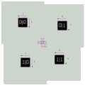
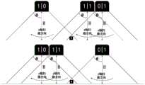
要对HTC VIVE系统的跟踪效率进行提升,可以采用基站的扩展布局结构,不具有预置偏移的基站扩展布局结构如图7所示,图7中,中心位置处为基站,其上的数字为基站的编号,即00、01、10、11;周围边框区域代表基站的扫描范围,x、y为两个方向的激光扫描方向。这种拓展方式完全不会占用地面使用人员的移动空间,并且极为方便对各个基站进行编号,为后续的算法实现减少了许多困难。To improve the tracking efficiency of the HTC VIVE system, the extended layout structure of the base station can be used. The extended layout structure of the base station without preset offset is shown in Figure 7. In Figure 7, the center position is the base station, and the numbers on it are shown in Figure 7. is the number of the base station, namely 00, 01, 10, 11; the surrounding frame area represents the scanning range of the base station, and x and y are the laser scanning directions in two directions. This expansion method will not occupy the mobile space of ground users at all, and it is extremely convenient to number each base station, which reduces many difficulties for subsequent algorithm implementation.
但是使用图7的布局方式后,当进行工作时,处于图中1号位置的信号如图8所示。可以看出,在没有装配误差的情况下,Y方向仅仅有一个扫描信号(因为左右两个基站完全同步,所以信号重叠在一起)。同理,在2号位置,X方向仅仅有一个扫描信号。However, after using the layout in Figure 7, when working, the signal at the No. 1 position in the figure is shown in Figure 8. It can be seen that in the absence of assembly errors, there is only one scanning signal in the Y direction (because the left and right base stations are completely synchronized, the signals overlap each other). Similarly, at
但是考虑到装配时可能存在一些误差,导致Y方向信号分叉,成为两个相距很近的扫描信号。这类情况发生时,将难以分辨Y信号应该归属于哪个基站,将会在一定程度上降低跟踪系统的跟踪精度。However, considering that there may be some errors during assembly, the Y-direction signals are bifurcated and become two scan signals that are very close to each other. When such a situation occurs, it will be difficult to distinguish which base station the Y signal should belong to, which will reduce the tracking accuracy of the tracking system to a certain extent.
发明内容SUMMARY OF THE INVENTION
有鉴于此,本发明提供了一种可扩展的基站阵列、光学跟踪系统及其跟踪方法,实现了基站的扩展,并且通过预置偏移布局来实现更为精准、快速的信号分拣,从而获得更为精确、高效的跟踪系统及跟踪方法。In view of this, the present invention provides an expandable base station array, an optical tracking system and a tracking method thereof, which realizes the expansion of the base station, and realizes more accurate and fast signal sorting through the preset offset layout, thereby Obtain a more accurate and efficient tracking system and tracking method.
为达到上述目的,本发明的技术方案为:For achieving the above object, the technical scheme of the present invention is:
一种可扩展的基站阵列,由m行、n列共m×n个基站组成,其中相邻基站间扫描范围有重叠,以同一列基站、同一行基站均为直线排列时各基站所处位置为原位。An expandable base station array, consisting of m rows and n columns of m×n base stations, in which the scanning ranges between adjacent base stations overlap, and the positions of the base stations when the base stations in the same column and row are arranged in a straight line in situ.
行数和列数同为奇数或同为偶数的基站设置于原位。The base stations whose number of rows and columns are both odd or even are set in the original position.
行数和列数的奇偶不同的基站设置于原位右下方设定的偏移量处。Base stations with different parities in the number of rows and columns are set at the offset set at the bottom right of the home position.
设定的偏移量保证相邻基站之间扫描范围有重叠。The set offset ensures that the scanning ranges between adjacent base stations overlap.
本发明实施例还提供了一种基于可扩展的基站阵列的光学跟踪系统,系统包括可扩展的基站阵列、频闪器、接收器、同步控制器以及中央处理器;系统用于对待跟踪目标进行跟踪。The embodiment of the present invention also provides an optical tracking system based on an expandable base station array, the system includes an expandable base station array, a strobe, a receiver, a synchronization controller and a central processing unit; the system is used for tracking the target to be tracked. track.
可扩展的基站阵列采用上述的可扩展的基站阵列,可扩展的基站阵列平行于待跟踪目标所处平面,且可扩展的基站阵列高于待跟踪目标所处平面设定高度值。The expandable base station array adopts the above-mentioned expandable base station array. The expandable base station array is parallel to the plane where the target to be tracked is located, and the expandable base station array is higher than the set height value of the plane where the target to be tracked is located.
可扩展的基站阵列中每个基站对应设置一个频闪器。Each base station in the expandable base station array is provided with a strobe correspondingly.
可扩展的基站阵列中每个基站及其对应频闪器均连接至同步控制器。Each base station and its corresponding strobe in the expandable base station array is connected to the synchronization controller.
同步控制器控制频闪器在对应基站进行扫描前发射开始信号,并将开始信号的发射时间发送至中央处理器。The synchronization controller controls the strobe to transmit the start signal before scanning the corresponding base station, and sends the transmission time of the start signal to the central processing unit.
接收器设置于待跟踪目标上,接收可扩展的基站阵列中基站的扫描信号,并将扫描信号的接收时间反馈至中央处理器。The receiver is arranged on the target to be tracked, receives the scanning signal of the base station in the expandable base station array, and feeds back the receiving time of the scanning signal to the central processing unit.
中央处理器依据开始信号的发射时间、接收器针对同一基站的扫描信号的接收时间以及标定后的基站的内外参数计算所述接收器的位姿。The central processor calculates the pose of the receiver according to the transmission time of the start signal, the reception time of the scanning signal of the receiver for the same base station, and the calibrated internal and external parameters of the base station.
本发明实施例还提供了一种基于可扩展的基站阵列的光学跟踪方法,跟踪方法用于对待跟踪目标进行跟踪,包括如下步骤:The embodiment of the present invention also provides an optical tracking method based on an expandable base station array, where the tracking method is used to track a target to be tracked, including the following steps:
S1、在待跟踪目标上设置接收器。S1. Set a receiver on the target to be tracked.
S2、采用频闪器发射开始信号,由接收器接收。S2. A strobe is used to transmit a start signal, which is received by the receiver.
S3、采用上述实施例提供的可扩展的基站阵列对待跟踪目标先进行x方向扫描、再进行y方向的扫描,分别记录待跟踪目标对x方向和y方向扫描信号的接收时间。S3. Using the expandable base station array provided in the above embodiment, the target to be tracked is first scanned in the x direction and then in the y direction, and the receiving time of the scanning signal in the x direction and the y direction by the target to be tracked is recorded respectively.
S4、判断待跟踪目标对x方向和y方向扫描信号的接收时间对应基站。S4. Determine the base station corresponding to the receiving time of the scanning signal in the x-direction and the y-direction by the target to be tracked.
S5、依据开始信号的发射时间、接收器针对同一基站的扫描信号的接收时间以及设定高度值计算接收器的位姿。S5. Calculate the pose of the receiver according to the transmission time of the start signal, the reception time of the scanning signal of the receiver for the same base station, and the set height value.
进一步地,S4具体为:Further, S4 is specifically:
基站阵列的最小单元为由2行2列共4个基站组成的单元阵列;单元阵列的扫描区域分为4类,分别为第一区域、第二区域、第三区域以及第四区域;其中第一区域为仅能被一个基站的扫描范围覆盖的区域;第二区域为能被两个基站的扫描范围覆盖的区域;第三区域为能被三个基站的扫描范围覆盖的区域;第四区域为能被四个基站的扫描范围覆盖的区域。The minimum unit of the base station array is a unit array composed of 4 base stations in 2 rows and 2 columns; the scanning area of the unit array is divided into 4 types, namely the first area, the second area, the third area and the fourth area; One area is the area that can only be covered by the scanning range of one base station; the second area is the area that can be covered by the scanning range of two base stations; the third area is the area that can be covered by the scanning range of three base stations; the fourth area is the area that can be covered by the scanning range of three base stations It is the area that can be covered by the scanning range of four base stations.
将基站阵列的扫描范围投影至待跟踪目标所处平面,判断待跟踪目标位置所属单元阵列,且存在如下四种情况:Project the scanning range of the base station array to the plane where the target to be tracked is located, and determine the unit array to which the target position to be tracked belongs, and there are the following four situations:
若待跟踪目标位置在所属单元阵列的第一区域,则待跟踪目标仅接收到一个基站的一次x方向扫描信号和一次y方向扫描信号。If the position of the target to be tracked is in the first area of the unit array to which it belongs, the target to be tracked only receives one x-direction scan signal and one y-direction scan signal from one base station.
若待跟踪目标位置在所属单元阵列的第二区域,则待跟踪目标接收到对应两个基站的两次x方向扫描信号和两次y方向扫描信号,依据待跟踪目标在第二区域中位置判断两次x方向扫描信号的接收时间对应的基站,以及两次y方向扫描信号的接收时间对应的基站。If the position of the target to be tracked is in the second area of the unit array to which it belongs, the target to be tracked receives two scan signals in the x direction and two scan signals in the y direction corresponding to the two base stations, and judges based on the position of the target to be tracked in the second area The base station corresponding to the receiving time of the scanning signal in the x-direction twice, and the base station corresponding to the receiving time of the scanning signal in the y-direction twice.
若待跟踪目标位置在所属单元阵列的第三区域,则待跟踪目标接收到对应三个基站的三次x方向扫描信号和三次y方向扫描信号,并将扫描信号的接收时间反馈至中央处理器,中央处理器依据待跟踪目标在第三区域中位置判断三次x方向扫描信号的接收时间对应的基站,以及三次y方向扫描信号的接收时间对应的基站。If the position of the target to be tracked is in the third area of the unit array to which it belongs, the target to be tracked receives three scan signals in the x direction and three scan signals in the y direction corresponding to the three base stations, and feeds back the reception time of the scan signals to the central processing unit. The central processor determines, according to the position of the target to be tracked in the third area, the base station corresponding to the receiving time of the x-direction scanning signal three times, and the base station corresponding to the receiving time of the y-direction scanning signal three times.
若待跟踪目标位置在所属单元阵列的第四区域,则待跟踪目标接收到对应四个基站的四次x方向扫描信号和四次y方向扫描信号,并将扫描信号的接收时间反馈至中央处理器,中央处理器依据待跟踪目标在第四区域中位置判断四次x方向扫描信号的接收时间对应的基站,以及四次y方向扫描信号的接收时间对应的基站。If the position of the target to be tracked is in the fourth area of the unit array to which it belongs, the target to be tracked receives four scan signals in the x direction and four scan signals in the y direction corresponding to the four base stations, and feeds back the reception time of the scan signals to the central processing unit. The central processor determines the base station corresponding to the receiving time of the four times of scanning signals in the x direction and the base station corresponding to the receiving time of the four times of scanning signals in the y direction according to the position of the target to be tracked in the fourth area.
有益效果:Beneficial effects:
1、本发明实施例提供了一种可扩展的基站阵列,采用预置偏移布局的形式,所有的基站信号可以很顺利的进行分拣,并且由于其布局的周期性,扩展基站时也不会有任何问题,仍保证了基站的无限扩展,保证跟踪范围的大幅度扩展。且该种预置偏移布局来实现更为精准、快速的信号分拣,为后续构成更为精确、高效的跟踪系统及跟踪方法提供了基础。1. The embodiment of the present invention provides an expandable base station array. In the form of a preset offset layout, all base station signals can be sorted smoothly. There will be any problems, and the infinite expansion of the base station is still guaranteed, and the large expansion of the tracking range is guaranteed. Moreover, this preset offset layout realizes more accurate and fast signal sorting, which provides a basis for the subsequent construction of a more accurate and efficient tracking system and tracking method.
2、本发明实施例还提供了一种基于可扩展的基站阵列的光学跟踪系统,该系统针对可扩展的基站阵列进行光学跟踪的系统设计,由于采用了预置偏移布局的基站阵列布局形式,能够实现更为精准、快速的信号分拣,因此该光学跟踪系统能够快速区分每个基站的扫描信号时间,从而能够进行精确、高效的光学跟踪。2. The embodiment of the present invention also provides an optical tracking system based on an expandable base station array. The system is designed for an expandable base station array to perform optical tracking, because a base station array layout with a preset offset layout is adopted. , can achieve more accurate and fast signal sorting, so the optical tracking system can quickly distinguish the scanning signal time of each base station, so that accurate and efficient optical tracking can be performed.
3、本发明实施例提供了的一种基于扩展的基站阵列的光学跟踪方法,该方法基于可扩展的基站阵列的光学跟踪系统进行光学跟踪,给出了进行精确、快速的信号分拣的方法,能够快速区分每个基站的扫描信号时间,从而能够进行精确、高效的光学跟踪。3. An optical tracking method based on an extended base station array is provided in an embodiment of the present invention. The method performs optical tracking based on an optical tracking system of an expandable base station array, and provides a method for accurate and fast signal sorting. , which can quickly distinguish the scanning signal time of each base station, thereby enabling accurate and efficient optical tracking.
附图说明Description of drawings
图1为本发明实施例提供的一种可扩展的基站阵列的单元阵列布局结构图;1 is a structural diagram of a cell array layout of an expandable base station array provided by an embodiment of the present invention;
图2为本发明针对的HTC VIVE的跟踪系统的组成结构图;Fig. 2 is the composition structure diagram of the tracking system of HTC VIVE that the present invention is directed to;
图3为本发明针对的HTC VIVE中一个发射器工作时的接收器响应波形图;Fig. 3 is the receiver response waveform diagram when a transmitter works in the HTC VIVE that the present invention is directed to;
图4为本发明针对的HTC VIVE中基站扫描信号与接收器响应关系图;Fig. 4 is the base station scanning signal and the receiver response relation diagram in the HTC VIVE that the present invention is directed to;
图5为本发明实施例提供的跟踪方法流程图;5 is a flowchart of a tracking method provided by an embodiment of the present invention;
图6为本发明提供的采用可扩展基站阵列的光学跟踪系统布局结构图;FIG. 6 is a layout structural diagram of an optical tracking system using an expandable base station array provided by the present invention;
图7为不具有预置偏移的基站扩展布局结构图;Fig. 7 is a base station extended layout structure diagram without preset offset;
图8为传统的基站扩展布局结构下信号交叠区的信号示意图;Fig. 8 is the signal schematic diagram of the signal overlapping area under the traditional base station extended layout structure;
图9为本发明实施例提供的可扩展的基站阵列布局结构图;FIG. 9 is a layout structural diagram of an expandable base station array provided by an embodiment of the present invention;
图10为本发明实施例提供的可扩展的基站阵列布局的区域分布图;10 is a regional distribution diagram of an expandable base station array layout provided by an embodiment of the present invention;
图11(a)为本发明实施例提供的针对待跟踪目标位置在所属单元阵列的第一区域的情况下的x、y方向扫描信号状态图;11(a) is a state diagram of scanning signals in the x and y directions when the position of the target to be tracked is in the first area of the unit array to which it belongs, according to an embodiment of the present invention;
图11(b)为本发明实施例提供的针对待跟踪目标位置在所属单元阵列的第一区域的情况下的x、y方向扫描信号的接收时间顺序图;FIG. 11(b) is a time sequence diagram of receiving scanning signals in the x and y directions when the position of the target to be tracked is in the first area of the unit array to which it belongs, according to an embodiment of the present invention;
图12(a)为本发明实施例提供的针对待跟踪目标位置在所属单元阵列的第二区域的情况下的x、y方向扫描信号状态图;12(a) is a state diagram of scanning signals in the x and y directions when the position of the target to be tracked is in the second area of the cell array to which it belongs, according to an embodiment of the present invention;
图12(b)为本发明实施例提供的针对待跟踪目标位置在所属单元阵列的第二区域的情况下的x、y方向扫描信号的接收时间顺序图;FIG. 12(b) is a time sequence diagram of receiving scanning signals in the x and y directions when the position of the target to be tracked is in the second area of the unit array to which it belongs, according to an embodiment of the present invention;
图13(a)为本发明实施例提供的针对待跟踪目标位置在所属单元阵列的第三区域的情况下的x、y方向扫描信号状态图;13(a) is a state diagram of scanning signals in the x and y directions when the position of the target to be tracked is in the third region of the unit array to which it belongs, according to an embodiment of the present invention;
图13(b)为本发明实施例提供的针对待跟踪目标位置在所属单元阵列的第三区域的情况下的x、y方向扫描信号的接收时间顺序图;FIG. 13(b) is a time sequence diagram of receiving scanning signals in the x and y directions when the position of the target to be tracked is in the third area of the unit array to which it belongs, according to an embodiment of the present invention;
图14(a)为本发明实施例提供的针对待跟踪目标位置在所属单元阵列的第四区域的情况下的x、y方向扫描信号状态图;Figure 14(a) is a state diagram of scanning signals in the x and y directions when the position of the target to be tracked is in the fourth region of the cell array to which it belongs, according to an embodiment of the present invention;
图14(b)为本发明实施例提供的针对待跟踪目标位置在所属单元阵列的第四区域的情况下的x、y方向扫描信号的接收时间顺序图。FIG. 14( b ) is a time sequence diagram of receiving scanning signals in the x and y directions when the position of the target to be tracked is in the fourth area of the unit array to which it belongs, according to an embodiment of the present invention.
具体实施方式Detailed ways
下面结合附图并举实施例,对本发明进行详细描述。The present invention will be described in detail below with reference to the accompanying drawings and embodiments.
实施例1Example 1
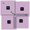
本发明提供了一种可扩展的基站阵列,该阵列的布局结构如图9所示,由m行、n列共m×n个基站组成,其中相邻基站间扫描范围有重叠,以同一列基站、同一行基站均为直线排列时各基站所处位置为原位。The present invention provides an expandable base station array. The layout structure of the array is shown in FIG. 9 , which consists of m×n base stations in m rows and n columns. When the base stations and the base stations in the same row are arranged in a straight line, the position of each base station is the original position.
行数和列数同为奇数或同为偶数的基站设置于原位。The base stations whose number of rows and columns are both odd or even are set in the original position.
行数和列数的奇偶不同的基站设置于原位右下方设定的偏移量处。偏移量为预先设置的数值。Base stations with different parities in the number of rows and columns are set at the offset set at the bottom right of the home position. The offset is a preset value.
设定的偏移量保证相邻基站之间扫描范围有重叠。The set offset ensures that the scanning ranges between adjacent base stations overlap.
本发明实施例提供的可扩展的基站阵列的最小单元为由2行2列共4个基站组成的单元阵列,单元阵列布局结构如图1所示。The minimum unit of the expandable base station array provided by the embodiment of the present invention is a unit array composed of four base stations in 2 rows and 2 columns. The layout structure of the unit array is shown in FIG. 1 .
本发明实施例给出一种具体的设置方式:基站原点之间相距4米,距离地面高度4米,基站的预置偏移量为25厘米。The embodiment of the present invention provides a specific setting method: the distance between the origins of the base stations is 4 meters, the height from the ground is 4 meters, and the preset offset of the base stations is 25 cm.
本发明实施例提供的基站布局方式为预置偏移布局,将基站分为(0,1,2,…,m)行与(0,1,2,…,n)列,将基站按照其行列数进行编号,然后将所有行列数同为奇数或同为偶数的基站保持原位,将奇偶不同的基站向右下方小幅度移动一段距离,如图9所示,本发明实施例中也可以设置向右方与下方各移动20cm。保证相邻基站之间扫描范围有重叠部分。完成该布局后,所有的基站信号可以很顺利的进行分拣,并且由于其布局的周期性,扩展基站时也不会有任何问题,仍保证了基站的无限扩展,保证跟踪范围的大幅度扩展。The base station layout provided by the embodiment of the present invention is a preset offset layout, the base stations are divided into (0, 1, 2, ..., m) rows and (0, 1, 2, ..., n) columns, and the base stations are arranged according to their The number of rows and columns is numbered, and then all the base stations with the same odd or even number of rows and columns are kept in their original positions, and the base stations with different parities are moved a small distance to the lower right, as shown in FIG. 9 , in the embodiment of the present invention, the Set to move 20cm to the right and down. Ensure that the scanning range between adjacent base stations overlaps. After the layout is completed, all base station signals can be sorted smoothly, and due to the periodicity of the layout, there will be no problem when expanding the base station, and the infinite expansion of the base station is still guaranteed, and the tracking range is greatly expanded. .
实施例2Example 2
本发明实施例基于上述可扩展的基站阵列提出了如图6所示的光学跟踪系统,系统包括可扩展的基站阵列、频闪器、接收器、同步控制器以及中央处理器;系统用于对待跟踪目标进行跟踪。The embodiment of the present invention proposes an optical tracking system as shown in FIG. 6 based on the above-mentioned expandable base station array. The system includes an expandable base station array, a strobe, a receiver, a synchronization controller, and a central processing unit; the system is used to treat Track the target for tracking.
可扩展的基站阵列采用如权利要求1的可扩展的基站阵列,可扩展的基站阵列平行于待跟踪目标所处平面,且可扩展的基站阵列高于待跟踪目标所处平面设定高度值。The expandable base station array adopts the expandable base station array as claimed in
可扩展的基站阵列中每个基站对应设置一个频闪器。Each base station in the expandable base station array is provided with a strobe correspondingly.
可扩展的基站阵列中每个基站及其对应频闪器均连接至同步控制器。Each base station and its corresponding strobe in the expandable base station array is connected to the synchronization controller.
同步控制器控制频闪器在对应基站进行扫描前发射开始信号,并将开始信号的发射时间发送至中央处理器。The synchronization controller controls the strobe to transmit the start signal before scanning the corresponding base station, and sends the transmission time of the start signal to the central processing unit.
接收器设置于待跟踪目标上,接收可扩展的基站阵列中基站的扫描信号,并将扫描信号的接收时间反馈至中央处理器。The receiver is arranged on the target to be tracked, receives the scanning signal of the base station in the expandable base station array, and feeds back the receiving time of the scanning signal to the central processing unit.
中央处理器依据开始信号的发射时间、接收器针对同一基站的扫描信号的接收时间以及标定后的基站的内外参数计算所述接收器的位姿,其中对于基站的标定采用本领域通用方法即可。The central processor calculates the position and attitude of the receiver according to the transmission time of the start signal, the reception time of the scanning signal of the receiver for the same base station, and the internal and external parameters of the calibrated base station, wherein the calibration of the base station can adopt a general method in the art. .
实施例3Example 3
针对上述基于可扩展的基站阵列的光学跟踪系统,本发明实施例还提供了一种基于可扩展的基站阵列的光学跟踪方法,其流程如图5所示,该跟踪方法用于对待跟踪目标进行跟踪;For the above-mentioned optical tracking system based on an expandable base station array, an embodiment of the present invention further provides an optical tracking method based on an expandable base station array, the process of which is shown in FIG. track;
S1、在待跟踪目标上设置接收器;S1. Set the receiver on the target to be tracked;
S2、采用设置在设定高度的频闪器发射开始信号,由接收器接收;S2. Use the strobe set at the set height to transmit the start signal, which is received by the receiver;
S3、采用设置在设定高度的如权利要求1的可扩展的基站阵列对待跟踪目标先进行x方向扫描、再进行y方向的扫描,分别记录待跟踪目标对x方向和y方向扫描信号的接收时间;S3, adopt the scalable base station array set at the set height as claimed in
S4、判断待跟踪目标对x方向和y方向扫描信号的接收时间对应基站;S4, judging the base station corresponding to the receiving time of the x-direction and y-direction scanning signals of the target to be tracked;
S5、依据开始信号的发射时间、接收器针对同一基站的扫描信号的接收时间以及设定高度计算接收器的位姿。S5. Calculate the pose of the receiver according to the transmission time of the start signal, the reception time of the scanning signal of the receiver for the same base station, and the set height.
其中S4具体为:Among them, S4 is specifically:
基站阵列的最小单元为由2行2列共4个基站组成的单元阵列。The minimum unit of the base station array is a unit array composed of 4 base stations in 2 rows and 2 columns.
单元阵列的扫描区域分为4类,分别为第一区域、第二区域、第三区域以及第四区域。The scanning area of the unit array is divided into four types, namely the first area, the second area, the third area and the fourth area.
其中第一区域为仅能被一个基站的扫描范围覆盖的区域;第二区域为能被两个基站的扫描范围覆盖的区域;第三区域为能被三个基站的扫描范围覆盖的区域;第四区域为能被四个基站的扫描范围覆盖的区域;区域分布如图10所示。The first area is the area that can only be covered by the scanning range of one base station; the second area is the area that can be covered by the scanning range of two base stations; the third area is the area that can be covered by the scanning range of three base stations; Four areas are areas that can be covered by the scanning range of four base stations; the area distribution is shown in Figure 10 .
将基站阵列的扫描范围投影至待跟踪目标所处平面,判断待跟踪目标位置所属单元阵列,且存在如下四种情况:Project the scanning range of the base station array to the plane where the target to be tracked is located, and determine the unit array to which the target position to be tracked belongs, and there are the following four situations:
若待跟踪目标位置在所属单元阵列的第一区域,则待跟踪目标仅接收到一个基站的一次x方向扫描信号和一次y方向扫描信号。可以直接判断属于同一个基站的扫描信号接收时间。If the position of the target to be tracked is in the first area of the unit array to which it belongs, the target to be tracked only receives one x-direction scan signal and one y-direction scan signal from one base station. The receiving time of the scanning signals belonging to the same base station can be directly judged.
若待跟踪目标位置在所属单元阵列的第二区域,则待跟踪目标接收到对应两个基站的两次x方向扫描信号和两次y方向扫描信号,并将扫描信号的接收时间反馈至中央处理器,中央处理器依据待跟踪目标在第二区域中位置判断两次x方向扫描信号的接收时间对应的基站,以及两次y方向扫描信号的接收时间对应的基站,从而获取接收器针对同一基站的扫描信号的接收时间。If the position of the target to be tracked is in the second area of the unit array to which it belongs, the target to be tracked receives two scan signals in the x direction and two scan signals in the y direction corresponding to the two base stations, and feeds back the reception time of the scan signals to the central processing unit. According to the position of the target to be tracked in the second area, the central processor determines the base station corresponding to the receiving time of the scanning signal in the x-direction twice, and the base station corresponding to the receiving time of the scanning signal in the y-direction twice, so as to obtain the receiver for the same base station. The reception time of the scan signal.
若待跟踪目标位置在所属单元阵列的第三区域,则待跟踪目标接收到对应三个基站的三次x方向扫描信号和三次y方向扫描信号,并将扫描信号的接收时间反馈至中央处理器,中央处理器依据待跟踪目标在第三区域中位置判断三次x方向扫描信号的接收时间对应的基站,以及三次y方向扫描信号的接收时间对应的基站,从而获取接收器针对同一基站的扫描信号的接收时间。If the position of the target to be tracked is in the third area of the unit array to which it belongs, the target to be tracked receives three scan signals in the x direction and three scan signals in the y direction corresponding to the three base stations, and feeds back the reception time of the scan signals to the central processing unit. According to the position of the target to be tracked in the third area, the central processor determines the base station corresponding to the receiving time of the x-direction scanning signal three times, and the base station corresponding to the receiving time of the y-direction scanning signal three times, so as to obtain the receiver's scanning signal for the same base station. receive time.
若待跟踪目标位置在所属单元阵列的第四区域,则待跟踪目标接收到对应四个基站的四次x方向扫描信号和四次y方向扫描信号,并将扫描信号的接收时间反馈至中央处理器,中央处理器依据待跟踪目标在第四区域中位置判断四次x方向扫描信号的接收时间对应的基站,以及四次y方向扫描信号的接收时间对应的基站,并依据开始信号的发射时间、接收器针对同一基站的扫描信号的接收时间以及设定高度值计算接收器的位姿。If the position of the target to be tracked is in the fourth area of the unit array to which it belongs, the target to be tracked receives four scan signals in the x direction and four scan signals in the y direction corresponding to the four base stations, and feeds back the reception time of the scan signals to the central processing unit. The central processor determines the base station corresponding to the receiving time of the four scan signals in the x direction and the base station corresponding to the receiving time of the four scan signals in the y direction according to the position of the target to be tracked in the fourth area, and according to the transmission time of the start signal , the receiver calculates the pose of the receiver according to the receiving time of the scanning signal of the same base station and the set height value.
本发明实施例中,在所有区域中选取四个点作为具体实例进行陈述:如图10所示,1号位置处于第一区域,仅能被(0,0)号基站扫描到;2号位置处于第二区域,能同时被(0,1)号基站与(1,1)号基站扫描;3号位置处于第三区域,能同时被(0,1)、(1,0)与(1,1)号基站扫描到;4号位置处于第四区域,能同时被(0,0)、(0,1)、(1,0)、(1,1)号基站扫描到。In this embodiment of the present invention, four points are selected as specific examples in all areas to describe: as shown in FIG. 10, position No. 1 is in the first area and can only be scanned by base station No. (0, 0); position No. 2 is in the first area. In the second area, it can be scanned by base stations (0, 1) and (1, 1) at the same time;
首先对1号位置进行分析。扫描状态如图11(a)所示,接收器R收到的扫描光信号如图11(b)所示。则按照技术方案2中,得到了两个时间信息后,结合已知的高度H,便可以计算出此点(接收器R)的位姿。First,
然后对2号位置进行分析。扫描状态如图12(a)所示,在x、y方向,交叠情况不同;接收器R收到的扫描光信号如图12(b)所示。根据已知的扫描顺序,可以区分出图12(b)中的各个信号来自哪个基站,然后问题便与1号位置相同,不论提取出那一个基站对应的扫描信号,都可以按照技术方案2中,得到了两个时间信息后,结合已知的高度H,便可以计算出此点的位姿。Then
再对3号位置进行分析。扫描状态如图13(a)所示,在x、y方向,交叠情况不同;接收器R收到的扫描光信号如图13(b)所示。根据已知的扫描顺序,可以区分出图13(b)中的各个信号来自哪个基站,然后问题同样与1号位置相同,不论提取出那一个基站对应的扫描信号,都可以按照技术方案2中,得到了两个时间信息后,结合已知的高度H,便可以计算出此点的位姿。Then analyze
最后对4号位置进行分析。扫描状态如图14(a)所示,在x、y方向,交叠情况不同;接收器R收到的扫描光信号如图14(b)所示。根据已知的扫描顺序,可以区分出图14(b)中的各个信号来自哪个基站,然后问题同样与1号位置相同,不论提取出那一个基站对应的扫描信号,都可以按照技术方案2中,得到了两个时间信息后,结合已知的高度H,便可以计算出此点的位姿。Finally, position No. 4 is analyzed. The scanning state is shown in Figure 14(a), in the x and y directions, the overlapping conditions are different; the scanning optical signal received by the receiver R is shown in Figure 14(b). According to the known scanning sequence, it can be distinguished from which base station each signal in Figure 14(b) comes from, and then the problem is also the same as that of No. 1 position. No matter which base station corresponding scanning signal is extracted, it can be done according to
依据上述实施例,根据信号出现的位置所在的周期可以分辨出信号的扫描方向,同时,根据信号出现的顺序可知道发出该信号的基站的编号,以此便完全区分出来红色区域的所有信号的信号来源,也便可以结合技术方案2的计算方法计算出此时被跟踪物体所在的空间位置。According to the above embodiment, the scanning direction of the signal can be distinguished according to the period in which the signal appears, and at the same time, the number of the base station that sends the signal can be known according to the order in which the signal appears, so that all signals in the red area can be completely distinguished. The signal source can also be combined with the calculation method of the
通过这种“预置偏移布局”的方法,为扫描信号进行了以此“预排序”,大大减少了后期算法与软件上的压力,提高了位姿的计算速度与精度,更加利于物体的跟踪。Through this "preset offset layout" method, the scanning signal is "pre-sorted", which greatly reduces the pressure on the later algorithm and software, improves the calculation speed and accuracy of the pose, and is more conducive to the object's track.
至此,便完全解决了多基站同时进行跟踪时,信号过于复杂而难以区分的问题。So far, the problem that the signals are too complicated and difficult to distinguish when multiple base stations are tracking at the same time has been completely solved.
综上,以上仅为本发明的较佳实施例而已,并非用于限定本发明的保护范围。凡在本发明的精神和原则之内,所作的任何修改、等同替换、改进等,均应包含在本发明的保护范围之内。In conclusion, the above are only preferred embodiments of the present invention, and are not intended to limit the protection scope of the present invention. Any modification, equivalent replacement, improvement, etc. made within the spirit and principle of the present invention shall be included within the protection scope of the present invention.
Claims (3)
Translated fromChinesePriority Applications (1)
| Application Number | Priority Date | Filing Date | Title |
|---|---|---|---|
| CN201810126032.4ACN108414978B (en) | 2018-02-08 | 2018-02-08 | Extensible base station array, optical tracking system and tracking method thereof |
Applications Claiming Priority (1)
| Application Number | Priority Date | Filing Date | Title |
|---|---|---|---|
| CN201810126032.4ACN108414978B (en) | 2018-02-08 | 2018-02-08 | Extensible base station array, optical tracking system and tracking method thereof |
Publications (2)
| Publication Number | Publication Date |
|---|---|
| CN108414978A CN108414978A (en) | 2018-08-17 |
| CN108414978Btrue CN108414978B (en) | 2020-08-11 |
Family
ID=63128059
Family Applications (1)
| Application Number | Title | Priority Date | Filing Date |
|---|---|---|---|
| CN201810126032.4AActiveCN108414978B (en) | 2018-02-08 | 2018-02-08 | Extensible base station array, optical tracking system and tracking method thereof |
Country Status (1)
| Country | Link |
|---|---|
| CN (1) | CN108414978B (en) |
Citations (9)
| Publication number | Priority date | Publication date | Assignee | Title |
|---|---|---|---|---|
| EP2084839A1 (en)* | 2006-11-17 | 2009-08-05 | Xg Technology, Inc. | Time coordinated base station and antenna array for integer cycle and impulse modulation systems |
| CN205317940U (en)* | 2016-01-05 | 2016-06-15 | 深圳市易飞行科技有限公司 | Multiaxis unmanned aerial vehicle keeps away barrier system based on laser array |
| CN106131530A (en)* | 2016-08-26 | 2016-11-16 | 万象三维视觉科技(北京)有限公司 | A kind of bore hole 3D virtual reality display system and methods of exhibiting thereof |
| CN106772402A (en)* | 2017-03-16 | 2017-05-31 | 小派科技(上海)有限责任公司 | A kind of space positioning system and region cascade space-location method |
| CN106796107A (en)* | 2014-08-10 | 2017-05-31 | 脸谱公司 | For the structure light of 3D sensings |
| CN106950541A (en)* | 2017-02-23 | 2017-07-14 | 成都理想境界科技有限公司 | A kind of alignment system, locating base station, locating base station network and positioning terminal |
| CN107040990A (en)* | 2017-03-31 | 2017-08-11 | 成都理想境界科技有限公司 | A kind of anti-Dual base stations alignment system blocked, positioning network and positioning terminal |
| CN206757033U (en)* | 2017-04-26 | 2017-12-15 | 岭纬公司 | The solid-state laser radar scanner of multiple collector |
| CN107509245A (en)* | 2017-07-06 | 2017-12-22 | 北京理工大学 | A kind of extension tracking based on HTC VIVE |
Family Cites Families (2)
| Publication number | Priority date | Publication date | Assignee | Title |
|---|---|---|---|---|
| US10078218B2 (en)* | 2016-01-01 | 2018-09-18 | Oculus Vr, Llc | Non-overlapped stereo imaging for virtual reality headset tracking |
| US10684479B2 (en)* | 2016-06-15 | 2020-06-16 | Vrvaorigin Vision Technology Corp. Ltd. | Head-mounted personal multimedia systems and visual assistance devices thereof |
- 2018
- 2018-02-08CNCN201810126032.4Apatent/CN108414978B/enactiveActive
Patent Citations (9)
| Publication number | Priority date | Publication date | Assignee | Title |
|---|---|---|---|---|
| EP2084839A1 (en)* | 2006-11-17 | 2009-08-05 | Xg Technology, Inc. | Time coordinated base station and antenna array for integer cycle and impulse modulation systems |
| CN106796107A (en)* | 2014-08-10 | 2017-05-31 | 脸谱公司 | For the structure light of 3D sensings |
| CN205317940U (en)* | 2016-01-05 | 2016-06-15 | 深圳市易飞行科技有限公司 | Multiaxis unmanned aerial vehicle keeps away barrier system based on laser array |
| CN106131530A (en)* | 2016-08-26 | 2016-11-16 | 万象三维视觉科技(北京)有限公司 | A kind of bore hole 3D virtual reality display system and methods of exhibiting thereof |
| CN106950541A (en)* | 2017-02-23 | 2017-07-14 | 成都理想境界科技有限公司 | A kind of alignment system, locating base station, locating base station network and positioning terminal |
| CN106772402A (en)* | 2017-03-16 | 2017-05-31 | 小派科技(上海)有限责任公司 | A kind of space positioning system and region cascade space-location method |
| CN107040990A (en)* | 2017-03-31 | 2017-08-11 | 成都理想境界科技有限公司 | A kind of anti-Dual base stations alignment system blocked, positioning network and positioning terminal |
| CN206757033U (en)* | 2017-04-26 | 2017-12-15 | 岭纬公司 | The solid-state laser radar scanner of multiple collector |
| CN107509245A (en)* | 2017-07-06 | 2017-12-22 | 北京理工大学 | A kind of extension tracking based on HTC VIVE |
Non-Patent Citations (3)
| Title |
|---|
| A LOW-COST LIGHTHOUSE-BASED VIRTUAL REALITY HEAD TRACKING SYSTEM;Adrian K. T. Ng,et al;《IEEE》;20171231;p1-5* |
| An Improved Method of Pose Estimation for Lighthouse Base Station Extension;Yi Yang,et al;《sensors》;20171022;p1-14* |
| 基于Unity3D和htcvive的虚拟现实游戏设计与实现;刘氢;《通信世界》;20170228;第43页* |
Also Published As
| Publication number | Publication date |
|---|---|
| CN108414978A (en) | 2018-08-17 |
Similar Documents
| Publication | Publication Date | Title |
|---|---|---|
| US11587252B2 (en) | Positioning method and system combining mark point positioning and intelligent reverse positioning | |
| CN106780601B (en) | Spatial position tracking method and device and intelligent equipment | |
| CN102840825B (en) | Particle locating system and method | |
| CN102169366B (en) | Multi-target tracking method in three-dimensional space | |
| CN101916152B (en) | Multi-touch infrared positioning device and method | |
| CN108010121B (en) | Method, computer-readable medium and measurement system for processing scan data | |
| US20130033449A1 (en) | Identification method for simultaneously identifying multiple touch points on touch screens | |
| CN105929963A (en) | Method for tracing eyeball position and detection device | |
| CN106803913A (en) | A kind of detection method and its device of the action that taken the floor for Auto-Sensing student | |
| CN106908764B (en) | A multi-target optical tracking method | |
| CN106547014B (en) | The generation method of crystal localization method and look-up table | |
| CN105335021A (en) | Laser radar based man-machine interaction system | |
| CN107509245B (en) | Extended tracking method based on HTC VIVE | |
| CN105302381B (en) | Infrared touch screen precision adjustment method and device | |
| CN109361909A (en) | Projection display system and projection correction's method | |
| CN115878064A (en) | Flight simulator visual display image distortion detection method and grid projection device | |
| CN117589061A (en) | Workpiece position detection system | |
| CN108414978B (en) | Extensible base station array, optical tracking system and tracking method thereof | |
| CN116775797A (en) | Urban space holographic map construction method based on multi-source big data fusion | |
| CN100359286C (en) | The method of image processing to improve the accuracy of laser measurement | |
| CN1035567A (en) | A kind of passing through a collimating system | |
| CN109992164A (en) | Laser Scanning Touch Screen | |
| CN108414979B (en) | An Optical Tracking Method Based on Scalable Base Station Array | |
| CN118331330A (en) | An optical tracking device for position deviation between multiple objects and a coordination method thereof | |
| CN108989718A (en) | Beacon beam acquisition and tracking device and beacon beam method for capturing and tracing |
Legal Events
| Date | Code | Title | Description |
|---|---|---|---|
| PB01 | Publication | ||
| PB01 | Publication | ||
| SE01 | Entry into force of request for substantive examination | ||
| SE01 | Entry into force of request for substantive examination | ||
| GR01 | Patent grant | ||
| GR01 | Patent grant | ||
| CB03 | Change of inventor or designer information | Inventor after:Weng Dongdong Inventor after:Xun Hang Inventor after:Li Dong Inventor after:Hu Xiang Inventor after:Li Yue Inventor after:Luo Le Inventor before:Weng Dongdong Inventor before:Xun Hang Inventor before:Li Dong Inventor before:Hu Xiang Inventor before:Li Yue | |
| CB03 | Change of inventor or designer information |