CN108376841B - A broadband dual-polarized antenna with high front-to-back ratio with sidewall structure - Google Patents
A broadband dual-polarized antenna with high front-to-back ratio with sidewall structureDownload PDFInfo
- Publication number
- CN108376841B CN108376841BCN201810017116.4ACN201810017116ACN108376841BCN 108376841 BCN108376841 BCN 108376841BCN 201810017116 ACN201810017116 ACN 201810017116ACN 108376841 BCN108376841 BCN 108376841B
- Authority
- CN
- China
- Prior art keywords
- balun
- vibrator
- back ratio
- reflector
- polarized antenna
- Prior art date
- Legal status (The legal status is an assumption and is not a legal conclusion. Google has not performed a legal analysis and makes no representation as to the accuracy of the status listed.)
- Expired - Fee Related
Links
Images


Classifications
- H—ELECTRICITY
- H01—ELECTRIC ELEMENTS
- H01Q—ANTENNAS, i.e. RADIO AERIALS
- H01Q19/00—Combinations of primary active antenna elements and units with secondary devices, e.g. with quasi-optical devices, for giving the antenna a desired directional characteristic
- H01Q19/02—Details
- H01Q19/021—Means for reducing undesirable effects
- H—ELECTRICITY
- H01—ELECTRIC ELEMENTS
- H01Q—ANTENNAS, i.e. RADIO AERIALS
- H01Q1/00—Details of, or arrangements associated with, antennas
- H01Q1/36—Structural form of radiating elements, e.g. cone, spiral, umbrella; Particular materials used therewith
- H01Q1/38—Structural form of radiating elements, e.g. cone, spiral, umbrella; Particular materials used therewith formed by a conductive layer on an insulating support
- H—ELECTRICITY
- H01—ELECTRIC ELEMENTS
- H01Q—ANTENNAS, i.e. RADIO AERIALS
- H01Q1/00—Details of, or arrangements associated with, antennas
- H01Q1/50—Structural association of antennas with earthing switches, lead-in devices or lightning protectors
- H—ELECTRICITY
- H01—ELECTRIC ELEMENTS
- H01Q—ANTENNAS, i.e. RADIO AERIALS
- H01Q19/00—Combinations of primary active antenna elements and units with secondary devices, e.g. with quasi-optical devices, for giving the antenna a desired directional characteristic
- H01Q19/10—Combinations of primary active antenna elements and units with secondary devices, e.g. with quasi-optical devices, for giving the antenna a desired directional characteristic using reflecting surfaces
- H01Q19/104—Combinations of primary active antenna elements and units with secondary devices, e.g. with quasi-optical devices, for giving the antenna a desired directional characteristic using reflecting surfaces using a substantially flat reflector for deflecting the radiated beam, e.g. periscopic antennas
Landscapes
- Waveguide Aerials (AREA)
- Aerials With Secondary Devices (AREA)
- Variable-Direction Aerials And Aerial Arrays (AREA)
Abstract
Translated fromChinese
Description
Translated fromChinese技术领域technical field
本发明涉及移动通信技术领域,特别是涉及一种具有边墙结构的高前后比宽带双极化天线。The invention relates to the technical field of mobile communication, in particular to a high-front-to-back ratio broadband dual-polarized antenna with a sidewall structure.
背景技术Background technique
宽带双极化天线在移动通信领域的应用越来越广泛,这些天线除了具有较大的带宽,还需要具有较高的前后比,才能够有效地抗多径衰落,提高信息传输速度和系统容量。Broadband dual-polarized antennas are more and more widely used in the field of mobile communications. In addition to large bandwidths, these antennas also need to have a high front-to-back ratio to effectively resist multipath fading and improve information transmission speed and system capacity. .
但现有的满足移动通信双极化天线性能要求的天线虽然具有较大的带宽,但是只能在某个特定的频段实现较好的前后比,无法满足能够在较大频率范围内实现高前后比的性能要求。However, although the existing antennas that meet the performance requirements of mobile communication dual-polarized antennas have large bandwidths, they can only achieve a good front-to-back ratio in a specific frequency band, and cannot achieve high front-to-back ratios in a wide frequency range. than the performance requirements.
发明内容SUMMARY OF THE INVENTION
为克服现有技术的不足,本发明的目的在于提供一种结构合理、工艺简单、产品质量稳定的边墙结构宽带双极化天线,具有高前后比、宽频带和双极化三种性能,能够有效提高系统容量和信息传输速度。In order to overcome the deficiencies of the prior art, the purpose of the present invention is to provide a sidewall structure broadband dual-polarization antenna with reasonable structure, simple process and stable product quality, which has three performances of high front-to-back ratio, wide frequency band and dual polarization, It can effectively improve the system capacity and information transmission speed.
本发明为解决其问题所采用的技术方案是:The technical scheme that the present invention adopts to solve its problem is:
一种具有边墙结构的高前后比宽带双极化天线,包括振子、巴伦、反射板、边墙和馈电接头,所述振子、巴伦和反射板均印刷于介质基板,所述振子固定在巴伦上方,所述反射板中心与振子中心处在同一垂直线上,所述巴伦垂直地焊接在反射板上,所述边墙为半圆柱状,所述边墙从四周紧密包围反射板,所述馈电接头设置在反射板下方。A high front-to-back ratio broadband dual-polarized antenna with a sidewall structure, comprising a vibrator, a balun, a reflector, a sidewall and a feed joint, the vibrator, the balun and the reflector are all printed on a dielectric substrate, and the vibrator Fixed above the balun, the center of the reflector and the center of the vibrator are on the same vertical line, the balun is vertically welded on the reflector, the side wall is semi-cylindrical, and the side wall closely surrounds the reflection from all sides board, and the feed connector is arranged below the reflector.
进一步地,所述边墙内部中空,所述边墙平行于反射板的边缘放置。Further, the interior of the side wall is hollow, and the side wall is placed parallel to the edge of the reflector.
进一步地,所述反射板为正方形结构,所述反射板中间位置开出一个圆孔,所述馈电接头穿过圆孔至反射板下方。Further, the reflector has a square structure, a circular hole is opened in the middle of the reflector, and the feed connector passes through the circular hole to the bottom of the reflector.
进一步地,所述振子开有四个用于与巴伦连接的槽孔,所述振子通过槽孔扣接在巴伦上方。Further, the vibrator is provided with four slot holes for connecting with the balun, and the vibrator is buckled above the balun through the slot holes.
进一步地,所述巴伦有两幅,两幅巴伦互相垂直,所述巴伦由两个对称且共面的金属贴片组成。Further, there are two baluns, the two baluns are perpendicular to each other, and the baluns are composed of two symmetrical and coplanar metal patches.
进一步地,所述巴伦的外露边缘呈圆弧渐变状。Further, the exposed edge of the balun is in the shape of an arc gradient.
进一步地,所述巴伦上端设有用于与振子相连的过渡段。Further, the upper end of the balun is provided with a transition section for connecting with the vibrator.
进一步地,所述振子为正方形结构,所述振子被两条互相垂直的缝隙划分成四块相同的方块区域。Further, the vibrator has a square structure, and the vibrator is divided into four identical square areas by two mutually perpendicular slits.
进一步地,所述方块区域的两个对角被切除以形成圆弧状。Further, two diagonal corners of the square area are cut off to form a circular arc shape.
进一步地,所述馈电接头连接有馈线,所述馈线焊接在巴伦内侧边缘。Further, the feeder joint is connected with a feeder, and the feeder is welded to the inner edge of the balun.
本发明的有益效果是:本发明采用的一种具有边墙结构的高前后比宽带双极化天线,由于反射板四周围合的边墙采用半圆柱结构的优化方式,使得在满足宽频带和双极化要求的同时,前后比进一步提高,系统性能更优。The beneficial effects of the present invention are as follows: the high front-to-back ratio broadband dual-polarized antenna with a side wall structure adopted by the present invention, because the side walls surrounding the reflector adopts the optimization method of the semi-cylindrical structure, so that the wide-band and At the same time of dual polarization requirements, the front-to-back ratio is further improved, and the system performance is better.
附图说明Description of drawings
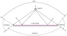
图1是平面反射板天线的辐射场示意图;Fig. 1 is a schematic diagram of the radiation field of a planar reflector antenna;
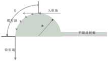
图2是圆柱体表面爬行波示意图;Fig. 2 is a schematic diagram of a creeping wave on the surface of a cylinder;
图3是半圆柱边墙爬行波衰减示意图;Figure 3 is a schematic diagram of the creeping wave attenuation of the semi-cylindrical side wall;
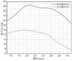
图4是爬行波随半圆柱半径衰减曲线图;Fig. 4 is the decay curve diagram of creeping wave with radius of semi-cylindrical;
图5是本发明实施例的立体图;5 is a perspective view of an embodiment of the present invention;
图6是本发明实施例的主视图;6 is a front view of an embodiment of the present invention;
图7是本发明实施例的左视图;7 is a left side view of an embodiment of the present invention;
图8是本发明实施例的俯视图;8 is a top view of an embodiment of the present invention;
图9是本发明实施例的天线振子示意图;9 is a schematic diagram of an antenna vibrator according to an embodiment of the present invention;
图10是本发明实施例的天线巴伦示意图;10 is a schematic diagram of an antenna balun according to an embodiment of the present invention;
图11是本发明实施例的天线反射板示意图;11 is a schematic diagram of an antenna reflector according to an embodiment of the present invention;
图12是本发明实施例的天线的驻波比VSWR(1)曲线;Fig. 12 is the standing wave ratio VSWR (1) curve of the antenna of the embodiment of the present invention;
图13是本发明实施例的天线的驻波比VSWR(2)曲线;Fig. 13 is the standing wave ratio VSWR (2) curve of the antenna of the embodiment of the present invention;
图14是本发明实施例的天线的隔离度S12曲线;Fig. 14 is the isolation degree S12 curve of the antenna of the embodiment of the present invention;
图15是本发明实施例的天线在2.2GHz上的辐射方向图;FIG. 15 is a radiation pattern of the antenna at 2.2 GHz according to an embodiment of the present invention;
图16是图11的二维表示图;Figure 16 is a two-dimensional representation of Figure 11;
图17是本发明实施例天线有边墙与无边墙时前后比曲线对比;17 is a comparison of the front-to-back ratio curves when the antenna has a side wall and without a side wall according to an embodiment of the present invention;
图中标号:1-振子;2-巴伦;3-反射板;4-边墙;5-馈电接头。Labels in the figure: 1-vibrator; 2-balun; 3-reflector; 4-side wall; 5-feed connector.
具体实施方式Detailed ways
下面结合附图和实例对本发明作进一步说明。The present invention will be further described below in conjunction with the accompanying drawings and examples.
如图5-8所示,本发明提供一种具有边墙结构的高前后比宽带双极化天线,由振子1、巴伦2、反射板3、边墙4和馈电接头5组成,且振子1、巴伦2以及反射板3均印刷于介质基板的平面上,介质基板相对介电常数为4.4,介质基板厚度均为0.8mm;巴伦2的外侧采用圆弧形状,双极化天线的两对巴伦2正交放置,每个巴伦2上端有一段过渡段,用于与振子1电路板相连;天线的辐射单元是类似箭头形状的振子1,并且在振子1的印刷电路上开出四个槽孔,用于与巴伦 2连接;天线的反射板3为正方形,在反射板3的四周,采用四个相同的半圆柱结构紧密包围,有效地提高前后比。天线的巴伦2垂直地焊接在反射板3上,半圆柱边墙4平行于反射板3的边缘放置,振子 1通过槽孔扣在巴伦2上方,且反射板3中心和振子1中心在同一垂直直线上,馈线焊接在巴伦2的直角腰边缘,通过馈线将馈电结头穿过反射板3的圆孔至反射板3下方。As shown in Figures 5-8, the present invention provides a high-front-to-back ratio broadband dual-polarized antenna with a sidewall structure, which is composed of a
之所以天线设置的边墙4为半圆柱状。这是由于根据几何绕射理论,当辐射体位于反射板3上方时,电磁波的辐射会形成三个不同的区域,分别是亮区,半阴影区和全阴影区,如图1所示。衍射是指声波、光波等各种波在传播时,如果被一个大小近于或小于波长的物体阻挡,就绕过这个物体,继续进行的现象,也称绕射。而在全阴影区只有衍射波的存在,这一衍射波是产生天线辐射后瓣的根源,因此,要想抑制后瓣辐射,必须要降低电磁波的衍射。The reason why the
当反射板3周围有障碍物时,电磁波会发生绕射,当有射线向光滑的理想导电曲面入射时,它将分为两部分:一部分入射能量继续前进,另一部分入射能量则沿着物体表面传播,成为表面射线,又称爬行波,如图2所示,表面射线在传播时将不断沿切向发出绕射线,电磁波传播时入射线和绕射线分别和表面上Q1和Q2相切,能量不断衰减,理论上说他要环绕封闭曲面爬行无穷多次,实际它的能量衰减很快,不会环绕一周以上,而由于天线的后瓣是绕射到天线反射板3后方的电磁波形成的,所以采用半圆柱的结构,从而减少正后方的电磁波,示意图如图3所示,爬行波随圆柱半径衰减曲线如图4所示,可以看出,圆柱半径越大,衰减越大。When there is an obstacle around the
本实施例中,为了减轻天线重量,边墙4内部为中空结构,且边墙4平行于反射板3的边缘放置。反射板3为正方形结构,正方形的反射板3的使用是基于该双极化天线的对称性,从而形成对称的方向图。在反射板3中间位置开出一个圆孔,馈电接头5穿过圆孔至反射板3下方。振子1开有四个用于与巴伦2连接的槽孔,振子1通过槽孔扣接在巴伦2上方。巴伦2有两幅,两幅巴伦2互相垂直,巴伦2 由两个对称且共面的金属贴片组成。In this embodiment, in order to reduce the weight of the antenna, the interior of the
巴伦2的外露边缘呈圆弧渐变状。这是由于任意实数负载阻抗在所希望的带宽上,都可以用多节匹配变换器匹配,当分立的节数增加时,各节之间的特性阻抗的阶跃变化随之减小,所以在无限多节的极限情况下,就形成了连续的渐变线,从而实现了较宽带宽的匹配,且圆弧所在圆的圆心和半径根据天线的性能及阻抗匹配要求确定。The exposed edge of the
巴伦2上端设有用于与振子1相连的过渡段。振子1为正方形结构,振子1被两条互相垂直的缝隙划分成四块相同的方块区域。方块区域的两个对角被切除以形成圆弧状。馈电接头5连接有馈线,馈线焊接在巴伦2内侧边缘。The upper end of the
具体实施时,天线的辐射振子1印刷在正方形介质基板上,如图 9所示,介质基板边长l1=56mm,再将印刷电路分成大小相等的四个小正方形块,相邻的两块间距为l4=2mm,在距离边沿l5=2mm处为圆心,以r1=8mm为半径做圆。并且在电路板上开出四个槽孔,长度为 l2=5mm,宽为l3=0.8mm,用于与巴伦2相连。In the specific implementation, the radiating
天线巴伦2也采用了印刷电路加工制作,如图10所示,一对巴伦2包括完全相同的两片,距离l6=2mm,高度为h2=45mm,单片宽度 l11=38mm,在巴伦2的上端有一段过渡段,用于将天线巴伦2电路板与辐射振子1所在的电路板连接,长为l7=5mm,高为h3=2mm,位置距离边缘l12=2mm,圆弧状的尺寸为,圆心位于l8=40mm,h1=32mm处,半径为r2=30mm。天线的馈电位置位于高度h4=41mm处。The
天线的反射板3为正方形,如图11所示,边长l9=170mm,同时沿着反射板3外边,紧密包围着四个完全相同的半圆柱状边墙4,边墙4的直径d=40mm,成螺旋状排列,在反射板3的正中央位置有一个半径为r3=4mm的圆孔,用于馈线的引入。The
采用全波电磁仿真软件对该天线进行了性能仿真,其两个端口的电压驻波比VSWR(1)和VSWR(2)分别如图12和图13所示,可以看出,天线在1.52GHz-3.08GHz频率范围内,电压驻波比均小于1.5,相对带宽可以到达67.8%。两个端口的隔离度S12如图14所示,在满足驻波比的带宽范围内,隔离度均大于22dB。图15所示是双极化天线xoz面的辐射方向图,图16是该方向图所对应的二维图,从中可以看出,半功率波束宽度为60-70度。图17是该天线的有边墙4 与无边墙4前后比曲线对比,从图中可以看出,有半圆柱边墙4时,天线的前后比频段两边大约为20dB,最大处则达到26.5dB,而当不加半圆柱边墙4结构时,前后比最大只能达到16dB,前后比最小处只有大约8dB,可见半圆柱边墙4结构使该天线的前后比得到了大大地改善。The performance of the antenna is simulated by using the full-wave electromagnetic simulation software. The voltage standing wave ratios VSWR(1) and VSWR(2) of the two ports are shown in Figure 12 and Figure 13, respectively. It can be seen that the antenna is operating at 1.52 GHz. In the frequency range of -3.08GHz, the voltage standing wave ratio is less than 1.5, and the relative bandwidth can reach 67.8%. The isolation S12 of the two ports is shown in Figure 14, and within the bandwidth range that satisfies the standing wave ratio, the isolation is both greater than 22dB. Figure 15 shows the radiation pattern of the xoz plane of the dual-polarized antenna, and Figure 16 is a two-dimensional diagram corresponding to the pattern, from which it can be seen that the half-power beam width is 60-70 degrees. Figure 17 is a comparison of the front-to-back ratio curves of the antenna with
以上所述,只是本发明的较佳实施例而已,本发明并不局限于上述实施方式,只要其以相同的手段达到本发明的技术效果,都应属于本发明的保护范围。The above descriptions are only preferred embodiments of the present invention, and the present invention is not limited to the above-mentioned embodiments, as long as the technical effects of the present invention are achieved by the same means, they should all belong to the protection scope of the present invention.
Claims (8)
Priority Applications (1)
| Application Number | Priority Date | Filing Date | Title |
|---|---|---|---|
| CN201810017116.4ACN108376841B (en) | 2018-01-05 | 2018-01-05 | A broadband dual-polarized antenna with high front-to-back ratio with sidewall structure |
Applications Claiming Priority (1)
| Application Number | Priority Date | Filing Date | Title |
|---|---|---|---|
| CN201810017116.4ACN108376841B (en) | 2018-01-05 | 2018-01-05 | A broadband dual-polarized antenna with high front-to-back ratio with sidewall structure |
Publications (2)
| Publication Number | Publication Date |
|---|---|
| CN108376841A CN108376841A (en) | 2018-08-07 |
| CN108376841Btrue CN108376841B (en) | 2020-08-04 |
Family
ID=63016430
Family Applications (1)
| Application Number | Title | Priority Date | Filing Date |
|---|---|---|---|
| CN201810017116.4AExpired - Fee RelatedCN108376841B (en) | 2018-01-05 | 2018-01-05 | A broadband dual-polarized antenna with high front-to-back ratio with sidewall structure |
Country Status (1)
| Country | Link |
|---|---|
| CN (1) | CN108376841B (en) |
Families Citing this family (3)
| Publication number | Priority date | Publication date | Assignee | Title |
|---|---|---|---|---|
| CN109301489B (en)* | 2018-09-06 | 2020-05-08 | 深圳大学 | Low-profile high-isolation differential dual-polarized slot antenna applied to 5G communication |
| CN109742521B (en)* | 2018-12-29 | 2021-01-22 | 京信通信技术(广州)有限公司 | Dual-polarization radiating element and antenna |
| CN113346220B (en)* | 2021-06-17 | 2024-12-06 | 华南理工大学 | A vertical base station antenna with high front-to-back ratio and communication equipment |
Citations (3)
| Publication number | Priority date | Publication date | Assignee | Title |
|---|---|---|---|---|
| CN101160692A (en)* | 2005-12-22 | 2008-04-09 | 凯瑟雷恩工厂两合公司 | Dual-polarized antenna having longitudinal or transverse webs |
| CN102790284A (en)* | 2012-07-02 | 2012-11-21 | 广东通宇通讯股份有限公司 | Antenna device with multiple boundaries and reflecting board thereof |
| CN105186108A (en)* | 2015-09-24 | 2015-12-23 | 广东博纬通信科技有限公司 | Low profile ultra wideband dual polarization high frequency oscillator unit |
Family Cites Families (2)
| Publication number | Priority date | Publication date | Assignee | Title |
|---|---|---|---|---|
| CN102013549B (en)* | 2010-09-17 | 2013-05-01 | 航天恒星科技有限公司 | Precise GNSS directional antenna |
| CN102570056B (en)* | 2012-02-10 | 2014-12-24 | 摩比天线技术(深圳)有限公司 | Ultrawide-band dual-polarized electrically-tunable antenna |
- 2018
- 2018-01-05CNCN201810017116.4Apatent/CN108376841B/ennot_activeExpired - Fee Related
Patent Citations (3)
| Publication number | Priority date | Publication date | Assignee | Title |
|---|---|---|---|---|
| CN101160692A (en)* | 2005-12-22 | 2008-04-09 | 凯瑟雷恩工厂两合公司 | Dual-polarized antenna having longitudinal or transverse webs |
| CN102790284A (en)* | 2012-07-02 | 2012-11-21 | 广东通宇通讯股份有限公司 | Antenna device with multiple boundaries and reflecting board thereof |
| CN105186108A (en)* | 2015-09-24 | 2015-12-23 | 广东博纬通信科技有限公司 | Low profile ultra wideband dual polarization high frequency oscillator unit |
Also Published As
| Publication number | Publication date |
|---|---|
| CN108376841A (en) | 2018-08-07 |
Similar Documents
| Publication | Publication Date | Title |
|---|---|---|
| CN107658568B (en) | Dual-frequency dual-polarization common-aperture waveguide horn planar array antenna | |
| US8451189B1 (en) | Ultra-wide band (UWB) artificial magnetic conductor (AMC) metamaterials for electrically thin antennas and arrays | |
| CN108987903A (en) | The series feed linear array circular polarization microstrip antenna of micro-strip | |
| CN110380217A (en) | High-gain end-on-fire antenna based on artificial surface plasmon | |
| CN111541031A (en) | A broadband low-profile transmission array antenna and wireless communication equipment | |
| WO2018130014A1 (en) | Multi-beam cavity-backed high gain antenna array | |
| CN108376841B (en) | A broadband dual-polarized antenna with high front-to-back ratio with sidewall structure | |
| CN110380233A (en) | A kind of low section Scanning Phased Array Antenna with Broadband | |
| CN110504542A (en) | Broadband dual-polarized high-density high-isolation array antenna loaded with composite isolator | |
| CN117220036A (en) | Asymmetric electromagnetic transparent base station antenna and array based on frequency selection surface | |
| CN117855859A (en) | Broadband Huygens super-surface unit, transmission array antenna and design method | |
| CN114899612B (en) | Circularly polarized airborne detection antenna based on double-row periodic arrangement | |
| CN115764251A (en) | Broadband antenna based on metamaterial | |
| CN215989247U (en) | Differential feed cross polarization high-gain antenna | |
| CN115395232A (en) | Same-frequency and same-polarization common-aperture antenna with high isolation and low correlation | |
| CN106785479A (en) | A kind of lobe millimeter wave micro-strip antenna wide based on plane single pole sub antenna | |
| CN114094353A (en) | An ultra-wideband tightly coupled array antenna | |
| Sifat et al. | High gain wideband log periodic dipole array antenna loaded with corrugations | |
| CN209730151U (en) | A kind of antenna and base station | |
| CN118232031A (en) | Dual-functional super surface, antenna unit, antenna array and communication equipment | |
| CN111509393A (en) | A one-dimensional planar periodic leaky-wave antenna based on microstrip line structure | |
| CN217114776U (en) | Base station antenna with small aperture and narrow beam | |
| CN214672987U (en) | Microstrip circular polarization array antenna with low axial ratio | |
| CN213753051U (en) | Broadband high-gain printed antenna | |
| CN110148829A (en) | A kind of broadband low section dual polarization cross dipole antenna based on the side annular surface AMC |
Legal Events
| Date | Code | Title | Description |
|---|---|---|---|
| PB01 | Publication | ||
| PB01 | Publication | ||
| SE01 | Entry into force of request for substantive examination | ||
| SE01 | Entry into force of request for substantive examination | ||
| GR01 | Patent grant | ||
| GR01 | Patent grant | ||
| CF01 | Termination of patent right due to non-payment of annual fee | ||
| CF01 | Termination of patent right due to non-payment of annual fee | Granted publication date:20200804 |