CN108354650B - A posterior cruciate ligament protection device - Google Patents
A posterior cruciate ligament protection deviceDownload PDFInfo
- Publication number
- CN108354650B CN108354650BCN201810381511.0ACN201810381511ACN108354650BCN 108354650 BCN108354650 BCN 108354650BCN 201810381511 ACN201810381511 ACN 201810381511ACN 108354650 BCN108354650 BCN 108354650B
- Authority
- CN
- China
- Prior art keywords
- bone
- handle
- knife
- pry
- cruciate ligament
- Prior art date
- Legal status (The legal status is an assumption and is not a legal conclusion. Google has not performed a legal analysis and makes no representation as to the accuracy of the status listed.)
- Expired - Fee Related
Links
- 210000002967posterior cruciate ligamentAnatomy0.000titleclaimsabstractdescription48
- 210000000988bone and boneAnatomy0.000claimsabstractdescription102
- 238000003780insertionMethods0.000claimsdescription10
- 230000037431insertionEffects0.000claimsdescription10
- 210000000689upper legAnatomy0.000claimsdescription10
- 241000587161GomphocarpusSpecies0.000claimsdescription5
- 210000005069earsAnatomy0.000claimsdescription3
- 229910001220stainless steelInorganic materials0.000claimsdescription3
- 239000010935stainless steelSubstances0.000claimsdescription3
- 241001079814Symphyotrichum pilosumSpecies0.000claims2
- 235000004224Typha angustifoliaNutrition0.000claims2
- 238000004519manufacturing processMethods0.000abstractdescription2
- 230000000903blocking effectEffects0.000abstract2
- 210000000629knee jointAnatomy0.000description6
- 101150106086PRY1 geneProteins0.000description5
- 238000010586diagramMethods0.000description4
- 238000011883total knee arthroplastyMethods0.000description4
- 230000033001locomotionEffects0.000description3
- 238000001356surgical procedureMethods0.000description3
- 210000003127kneeAnatomy0.000description2
- 238000000034methodMethods0.000description2
- 238000012986modificationMethods0.000description2
- 230000004048modificationEffects0.000description2
- 201000008482osteoarthritisDiseases0.000description2
- 238000004321preservationMethods0.000description2
- 210000002303tibiaAnatomy0.000description2
- 210000004353tibial menisciAnatomy0.000description2
- 238000011179visual inspectionMethods0.000description2
- 208000006820ArthralgiaDiseases0.000description1
- 229910000831SteelInorganic materials0.000description1
- 206010066902Surgical failureDiseases0.000description1
- 230000032683agingEffects0.000description1
- 230000009286beneficial effectEffects0.000description1
- 230000003412degenerative effectEffects0.000description1
- 230000000694effectsEffects0.000description1
- 230000005021gaitEffects0.000description1
- 230000001788irregularEffects0.000description1
- 230000008407joint functionEffects0.000description1
- 208000024765knee painDiseases0.000description1
- 210000001699lower legAnatomy0.000description1
- 208000015122neurodegenerative diseaseDiseases0.000description1
- 230000035790physiological processes and functionsEffects0.000description1
- 230000002980postoperative effectEffects0.000description1
- 230000009023proprioceptive sensationEffects0.000description1
- 238000011084recoveryMethods0.000description1
- 230000000087stabilizing effectEffects0.000description1
- 239000010959steelSubstances0.000description1
Images


Classifications
- A—HUMAN NECESSITIES
- A61—MEDICAL OR VETERINARY SCIENCE; HYGIENE
- A61B—DIAGNOSIS; SURGERY; IDENTIFICATION
- A61B17/00—Surgical instruments, devices or methods
- A61B17/16—Instruments for performing osteoclasis; Drills or chisels for bones; Trepans
- A61B17/1657—Bone breaking devices
- A—HUMAN NECESSITIES
- A61—MEDICAL OR VETERINARY SCIENCE; HYGIENE
- A61B—DIAGNOSIS; SURGERY; IDENTIFICATION
- A61B17/00—Surgical instruments, devices or methods
- A61B17/16—Instruments for performing osteoclasis; Drills or chisels for bones; Trepans
- A61B17/1662—Instruments for performing osteoclasis; Drills or chisels for bones; Trepans for particular parts of the body
- A61B17/1675—Instruments for performing osteoclasis; Drills or chisels for bones; Trepans for particular parts of the body for the knee
- A—HUMAN NECESSITIES
- A61—MEDICAL OR VETERINARY SCIENCE; HYGIENE
- A61B—DIAGNOSIS; SURGERY; IDENTIFICATION
- A61B17/00—Surgical instruments, devices or methods
- A61B17/16—Instruments for performing osteoclasis; Drills or chisels for bones; Trepans
- A61B17/17—Guides or aligning means for drills, mills, pins or wires
- A61B17/1732—Guides or aligning means for drills, mills, pins or wires for bone breaking devices
- A—HUMAN NECESSITIES
- A61—MEDICAL OR VETERINARY SCIENCE; HYGIENE
- A61B—DIAGNOSIS; SURGERY; IDENTIFICATION
- A61B17/00—Surgical instruments, devices or methods
- A61B17/16—Instruments for performing osteoclasis; Drills or chisels for bones; Trepans
- A61B17/17—Guides or aligning means for drills, mills, pins or wires
- A61B17/1739—Guides or aligning means for drills, mills, pins or wires specially adapted for particular parts of the body
- A61B17/1764—Guides or aligning means for drills, mills, pins or wires specially adapted for particular parts of the body for the knee
Landscapes
- Health & Medical Sciences (AREA)
- Surgery (AREA)
- Life Sciences & Earth Sciences (AREA)
- Orthopedic Medicine & Surgery (AREA)
- Biomedical Technology (AREA)
- Nuclear Medicine, Radiotherapy & Molecular Imaging (AREA)
- Oral & Maxillofacial Surgery (AREA)
- Engineering & Computer Science (AREA)
- Dentistry (AREA)
- Heart & Thoracic Surgery (AREA)
- Medical Informatics (AREA)
- Molecular Biology (AREA)
- Animal Behavior & Ethology (AREA)
- General Health & Medical Sciences (AREA)
- Public Health (AREA)
- Veterinary Medicine (AREA)
- Surgical Instruments (AREA)
Abstract
Description
Translated fromChinese技术领域technical field
本发明涉及技术领域,具体涉及一种后交叉韧带保护装置。The invention relates to the technical field, in particular to a posterior cruciate ligament protection device.
背景技术Background technique
随着社会老龄化的增加,罹患膝关节退变性疾病的中老年人数量逐年递增。我国罹患骨关节病的患者人数多达6500万,30岁以上人群的患病率为10%~17%,65岁以上人群为60%,75岁以上人群为80%,其中致残率高达53%。全膝关节置换术是治疗中晚期严重膝关节退变性骨关节炎的主要手段,可以有效缓解膝关节疼痛,重建关节功能和活动度,得到了广泛的临床应用,而在手术时后交叉韧带的完整保留对于膝关节的稳定性及术后膝关节本体感觉的恢复和行走步态起着至关重要的作用。With the increase of social aging, the number of middle-aged and elderly people suffering from knee degenerative diseases is increasing year by year. The number of patients with osteoarthritis in my country is as high as 65 million. The prevalence rate of people over 30 years old is 10% to 17%, 60% of people over 65 years old, and 80% of people over 75 years old. Among them, the disability rate is as high as 53%. %. Total knee arthroplasty is the main method for the treatment of severe knee degenerative osteoarthritis in the middle and late stages. It can effectively relieve knee pain, rebuild joint function and range of motion, and has been widely used in clinical practice. Intact preservation plays a crucial role in the stability of the knee joint and the recovery of knee joint proprioception and walking gait after surgery.
后交叉韧带是膝关节腔内非常重要的前后向和旋转稳定结构。后交叉韧带股骨的附着区位于股骨内髁的外侧面骨质,形状为半环形,宽度为19~21mm,向下后方向走行,止于胫骨内外髁关节面的后部骨质,呈不规则的四边形,内外侧宽度为10~12mm,并向后延伸到胫骨平台的下方约1cm处,其前方紧邻内外侧半月板后角的止点处。后交叉韧带具有限制胫骨后移、膝关节后伸、旋转和膝关节侧方活动的生理功能。The posterior cruciate ligament is a very important anterior and posterior stabilizing structure in the knee joint cavity. The attachment area of the posterior cruciate ligament to the femur is located on the lateral surface of the medial condyle of the femur, with a semi-circular shape and a width of 19-21 mm. It runs in the downward and posterior direction and inserts into the posterior bone of the articular surface of the medial and medial condyle of the tibia. It is irregular It is a quadrilateral with a medial and lateral width of 10-12 mm, and extends posteriorly to about 1 cm below the tibial plateau, and its front is close to the insertion point of the posterior angle of the medial and lateral meniscus. The posterior cruciate ligament has the physiological functions of restricting the posterior movement of the tibia, extension of the knee joint, rotation and lateral movement of the knee joint.
在现有的保留后交叉韧带型人工全膝关节置换手术中,由于没有专用的手术器械或装置保护后交叉韧带,只能通过目测或使用长钢钉来确定后交叉韧带下止点骨块的位置和大小,不仅费时费力,而且后交叉韧带保护效果欠佳。在用电动摆锯片进行胫骨平台截骨时,极易发生后交叉韧带胫骨侧下止点骨块部分撕脱或完全撕脱,引起后交叉韧带松弛,进而影响术后疗效和膝关节假体使用寿命,导致手术失败。In the existing total knee arthroplasty with preservation of the posterior cruciate ligament, since there is no special surgical instrument or device to protect the posterior cruciate ligament, the size of the inferior insertion point of the posterior cruciate ligament can only be determined by visual inspection or long steel nails. Position and size, not only time-consuming and laborious, but also poor protection of the posterior cruciate ligament. When the tibial plateau osteotomy is performed with an electric oscillating saw blade, it is very easy to cause partial avulsion or complete avulsion of the posterior cruciate ligament at the lower insertion point on the tibial side, causing the posterior cruciate ligament to relax, thereby affecting the postoperative curative effect and the knee joint prosthesis. service life, resulting in surgical failure.
因此,提供一种后交叉韧带保护装置,以避免手术过程中对后交叉韧带的误切割,是目前本领域技术人员急需解决的问题。Therefore, it is an urgent problem for those skilled in the art to provide a posterior cruciate ligament protection device to avoid miscutting the posterior cruciate ligament during surgery.
发明内容SUMMARY OF THE INVENTION
本发明的目的在于提供一种后交叉韧带保护装置,用于全膝关节置换术。The purpose of the present invention is to provide a posterior cruciate ligament protection device for total knee arthroplasty.
为实现上述目的,本发明采取以下技术方案:一种后交叉韧带保护装置,包括骨撬、骨刀和螺钉,In order to achieve the above object, the present invention adopts the following technical solutions: a posterior cruciate ligament protection device, comprising a bone pry, a bone knife and a screw,
所述骨撬包括手柄、辅助撬板和撬头,所述手柄、辅助撬板和撬头一体成型,所述手柄为扁平状,所述手柄的一端连接辅助撬板,所述辅助撬板为扁平弧形结构,与股骨滑车沟相匹配,在所述辅助撬板远离所述手柄的一端连接撬头,所述撬头由两侧臂组成,所述两侧臂之间形成U形开口,在所述手柄靠近所述辅助撬板的一端所述手柄上还设有孔槽和挡台,所述孔槽贯通所述手柄和挡台,所述孔槽孔壁上设有螺纹;The bone pry includes a handle, an auxiliary prying board and a prying head, the handle, the auxiliary prying board and the prying head are integrally formed, the handle is flat, and one end of the handle is connected to the auxiliary prying board, and the auxiliary prying board is The flat arc structure is matched with the trochlear groove of the femur, and a pry head is connected to the end of the auxiliary pry plate away from the handle. The pry head is composed of two arms, and a U-shaped opening is formed between the two arms. The handle is also provided with a hole groove and a stop on one end of the handle close to the auxiliary skid plate, the hole groove penetrates the handle and the stop, and the hole wall of the hole groove is provided with a thread;
所述骨刀包括一刀柄,刀柄为扁平状,刀柄的一端一体连接一刀头,所述刀柄上设置有一个开槽;The bone knife includes a handle, the handle is flat, one end of the handle is integrally connected with a cutter head, and a slot is arranged on the handle;
所述螺钉包括钉头和钉杆,所述钉头包括两个对称设置的旋耳,所述钉杆上设有螺纹。The screw includes a nail head and a nail shaft, the nail head includes two symmetrically arranged screw ears, and the nail shaft is provided with a thread.
所述螺钉从骨刀的开槽中穿入,再从骨撬手柄上的孔槽中穿出,将所述骨刀与骨撬螺接。The screw is inserted into the slot of the bone knife, and then passed out of the hole slot on the handle of the bone prying knife, and the bone knife is screwed with the bone prying knife.
所述两个侧臂的端部设置为V形,可以增强骨撬的把持力。The ends of the two side arms are arranged in a V shape, which can enhance the holding force of the bone pry.
为了避免压迫或损坏后交叉韧带,所述U形开口的高度为20-40mm。In order to avoid compressing or damaging the posterior cruciate ligament, the height of the U-shaped opening is 20-40mm.
所述骨刀位于开槽两侧的刀柄上设置有刻度线,可以准确读取骨刀插入骨的深度,避免人的目测造成的误差。The knife handle on both sides of the slot is provided with scale lines, which can accurately read the depth of the bone knife inserted into the bone and avoid errors caused by human visual inspection.
所述骨撬手柄上设有标记线,所述标记线与骨刀开槽两侧刀柄上刻度线配合,便于读取骨刀上的刻度。The bone pry handle is provided with a marking line, and the marking line cooperates with the scale lines on the knife handle on both sides of the slot of the bone knife, so that the scale on the bone knife is easy to read.
所述骨刀刀头相对于刀柄平面翘起一定高度,所述翘起的高度为0-20mm。The head of the bone knife is tilted to a certain height relative to the plane of the handle, and the tilted height is 0-20 mm.
所述骨刀刀头为直型刀头或U型刀头,根据手术需要选择不同刀头。The bone cutter head is a straight cutter head or a U-shaped cutter head, and different cutter heads are selected according to the needs of the operation.
为了手术操作方便,节省人力,所述骨撬手柄远离辅助撬板的一端上还设有挂环。In order to facilitate the operation and save manpower, a hanging ring is also provided on one end of the bone pry handle away from the auxiliary pry plate.
所述骨撬和骨刀均采用不锈钢材料制成。Both the bone pry and the bone knife are made of stainless steel.
有益效果beneficial effect
1、本发明后交叉韧带保护装置的骨撬撬头两个侧臂之间的U形开口具有更合适的高度,在手术过程中可以避免对后交叉韧带的伤害,两个侧臂的臂宽窄,可以增强骨撬的把持度,能更好的把持住胫骨平台,辅助撬板内表面的弧形与股骨滑车沟骨形相匹配,从而能更好的将股骨向前推出,便于截骨。1. The U-shaped opening between the two side arms of the bone pry head of the posterior cruciate ligament protection device of the present invention has a more suitable height, which can avoid damage to the posterior cruciate ligament during the operation, and the width of the two side arms is narrow. , which can enhance the holding degree of the bone pry, and can better hold the tibial platform. The arc shape of the inner surface of the auxiliary pry plate matches the shape of the trochlear groove of the femur, so that the femur can be better pushed forward, which is convenient for osteotomy.
2、本发明后交叉韧带保护装置将骨撬和骨刀组配,可以减少手术人数,节约人力。2. The posterior cruciate ligament protection device of the present invention is assembled with a bone lever and a bone knife, which can reduce the number of operations and save manpower.
3、本发明后交叉韧带保护装置设置有限位凸起和刻度,可以有效防止骨刀插入太深造成的后交叉韧带胫骨侧下止点撕脱骨折,并能准确判断骨刀插入位置。3. The posterior cruciate ligament protection device of the present invention is provided with limited protrusions and scales, which can effectively prevent the avulsion and fracture of the lower insertion point of the posterior cruciate ligament tibial side caused by too deep insertion of the osteotome, and can accurately determine the insertion position of the osteotome.
4、本发明后交叉韧带保护装置结构简单,使用方便并且制造成本低,极大地缩短了手术时间,提高了手术成功率。4. The posterior cruciate ligament protection device of the present invention has the advantages of simple structure, convenient use and low manufacturing cost, which greatly shortens the operation time and improves the success rate of the operation.
附图说明Description of drawings
图1本发明后交叉韧带保护装置整体结构示意图;1 is a schematic diagram of the overall structure of the posterior cruciate ligament protection device of the present invention;
图2本发明后交叉韧带保护装置骨撬不同角度的等轴测视图;Fig. 2 isometric views of different angles of the posterior cruciate ligament protection device of the present invention;
图3本发明后交叉韧带保护装置骨撬前视图;Figure 3 is a front view of the bone prying device of the posterior cruciate ligament protection device of the present invention;
图4本发明后交叉韧带保护装置骨撬后视图;Figure 4 is a rear view of the posterior cruciate ligament protection device of the present invention bone prying;
图5本发明后交叉韧带保护装置骨刀结构示意图;5 is a schematic structural diagram of the bone knife of the posterior cruciate ligament protection device of the present invention;
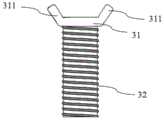
图6本发明后交叉韧带保护装置螺钉结构示意图;6 is a schematic diagram of the screw structure of the posterior cruciate ligament protection device of the present invention;
图7本发明后交叉韧带保护装置局部结构示意图;7 is a schematic diagram of the partial structure of the posterior cruciate ligament protection device of the present invention;
图8本发明另一优选实施例骨刀等轴测视图;Figure 8 isometric view of another preferred embodiment of the bone knife of the present invention;
图9本发明另一优选实施例骨刀左视图;Figure 9 is a left side view of another preferred embodiment of the osteotome of the present invention;
图中附图标记如下:The reference numbers in the figure are as follows:
骨撬1,骨刀2,螺钉3,手柄11,辅助撬板12,撬头13,孔槽14,挡台15,侧臂131,U形开口132,挂环111,标记线112,刀柄21,刀头22,开槽23,钉头31,钉杆32,旋耳311。Bone Pry 1, Bone Knife 2,
具体实施方式Detailed ways
以下实施例用于说明本发明,但不用来限制本发明的范围。若未特别指明,实施例中所用的技术手段为本领域技术人员所熟知的常规手段。下面结合附图和实施例对本发明进行详细的描述。The following examples are intended to illustrate the present invention, but not to limit the scope of the present invention. Unless otherwise specified, the technical means used in the examples are conventional means well known to those skilled in the art. The present invention will be described in detail below with reference to the accompanying drawings and embodiments.
如图1所示,本发明包括一骨撬1、与骨撬组配使用的骨刀2和螺钉3,As shown in FIG. 1, the present invention includes a
如图2-图4所示,所述骨撬1包括手柄11、辅助撬板12和撬头13,所述手柄11、辅助撬板12和撬头13一体成型,所述手柄11为扁平状,所述手柄11的一端连接辅助撬板12,所述辅助撬板12为扁平弧形结构,与股骨滑车沟相匹配,在所述辅助撬板12远离所述手柄11的一端连接撬头13,如图3和图4所示,所述撬头13由两侧臂131组成,所述两侧臂131之间形成U形开口132,U形开口132的高度为20-40mm,两个侧臂131的臂宽为10mm,在所述手柄11靠近所述辅助撬板12的一端所述手柄11上还设有孔槽14和挡台15,所述孔槽14贯通所述手柄11和挡台15,所述孔槽孔壁上设有螺纹;As shown in Figures 2-4, the
如图5所示,所述骨刀2包括一刀柄21,刀柄21为扁平状,刀柄21的一端一体连接一刀头22,所述刀柄21上设置有一个开槽23,所述骨刀2位于开槽23两侧的刀柄21上设置有刻度线,从刻度线上可以直接读取骨刀插入骨的深度。As shown in FIG. 5, the
如图6所示,所述螺钉3包括钉头31、钉杆32,所述钉头31包括两个对称设置的旋耳311,所述钉杆32上设有螺纹。As shown in FIG. 6 , the
所述螺钉3从骨刀2的开槽23中穿入,再从骨撬手柄11上的孔槽13中穿出,将所述骨刀2与骨撬1螺接,如图1。The
上述实施例中,骨撬1两个侧臂131的端部为V形,可以增强骨撬1的把持力,防止手术中骨撬与骨的脱离。In the above embodiment, the ends of the two
上述实施例中,如图7,骨撬1的手柄11上设有标记线112,标记线112可以辅助读取骨刀2插入骨的深度,当骨刀2准备插入骨时,所述骨撬手柄11上的标记线与骨刀2上的0刻度线正好对准,随后骨刀2向下插入骨中,骨刀插入骨的深度即为标记线所对的刻度线的读数。In the above-mentioned embodiment, as shown in FIG. 7 , the
上述实施例中,如图8和图9所示,所述骨刀2刀头22相对于刀柄21平面翘起一定高度a,如图9,所述翘起的高度为a,a为0-20mm。In the above embodiment, as shown in FIGS. 8 and 9 , the
上述实施例中,骨刀2刀头22为直型刀头或U型刀头。In the above embodiment, the
上述实施例中,在手柄11远离辅助撬板12的一端上还设有挂环111,如图2所示。In the above embodiment, a hanging
上述实施例中,骨撬1和骨刀2均采用不锈钢材料制成。In the above-mentioned embodiment, the
本发明后交叉韧带保护装置用于全膝关节置换术,在使用时首先使用骨撬1的辅助撬板12包裹在股骨的滑车沟和后交叉韧带前方,将撬头13的两侧臂131把持住胫骨平台并将后交叉韧带置于U形开口132处予以保护,然后手握持手柄1向后用力,进而带动辅助撬板12将胫骨平台相对股骨向前推出,使胫骨平台充分显露,此时将螺钉3插入骨刀2的开槽23和骨撬手柄11上的孔槽13中,手用力拧螺钉3的旋耳311将螺钉3旋紧,从而将骨撬1和骨刀2螺接,然后垂直于胫骨平台将刀头22插入胫骨平台骨质内,从骨刀2上的刻度读出骨刀2插入胫骨平台的深度,在插入合适深度后再进行截骨,由于有骨刀对后交叉韧带下止点进行保护,可以完整保留后交叉韧带胫骨平台止点骨质。The posterior cruciate ligament protection device of the present invention is used for total knee arthroplasty. When in use, the
虽然,上文中已经用一般性说明及具体实施方案对本发明作了详尽的描述,但在本发明基础上,可以对之作一些修改或改进,这对本领域技术人员而言是显而易见的。因此,在不偏离本发明精神的基础上所做的这些修改或改进,均属于本发明要求保护的范围。Although the present invention has been described in detail above with general description and specific embodiments, it is obvious to those skilled in the art that some modifications or improvements can be made on the basis of the present invention. Therefore, these modifications or improvements made without departing from the spirit of the present invention fall within the scope of the claimed protection of the present invention.
Claims (8)
Translated fromChinesePriority Applications (1)
| Application Number | Priority Date | Filing Date | Title |
|---|---|---|---|
| CN201810381511.0ACN108354650B (en) | 2018-04-25 | 2018-04-25 | A posterior cruciate ligament protection device |
Applications Claiming Priority (1)
| Application Number | Priority Date | Filing Date | Title |
|---|---|---|---|
| CN201810381511.0ACN108354650B (en) | 2018-04-25 | 2018-04-25 | A posterior cruciate ligament protection device |
Publications (2)
| Publication Number | Publication Date |
|---|---|
| CN108354650A CN108354650A (en) | 2018-08-03 |
| CN108354650Btrue CN108354650B (en) | 2020-08-11 |
Family
ID=63009144
Family Applications (1)
| Application Number | Title | Priority Date | Filing Date |
|---|---|---|---|
| CN201810381511.0AExpired - Fee RelatedCN108354650B (en) | 2018-04-25 | 2018-04-25 | A posterior cruciate ligament protection device |
Country Status (1)
| Country | Link |
|---|---|
| CN (1) | CN108354650B (en) |
Families Citing this family (1)
| Publication number | Priority date | Publication date | Assignee | Title |
|---|---|---|---|---|
| CN113303849B (en)* | 2021-06-30 | 2025-08-12 | 中国人民解放军陆军军医大学第二附属医院 | Medial collateral ligament protector for meniscus resection in knee joint replacement |
Citations (5)
| Publication number | Priority date | Publication date | Assignee | Title |
|---|---|---|---|---|
| US4686972A (en)* | 1986-04-30 | 1987-08-18 | Kurland Kenneth Z | Surgical deflector and drilling guide |
| US5334194A (en)* | 1990-04-11 | 1994-08-02 | Mikhail W F Michael | Collateral ligament retractor for use in performing knee surgery |
| CN105877821A (en)* | 2014-09-18 | 2016-08-24 | 周琦 | A multifunctional telescopic cutting scalpel for the discoid meniscus operation under a knee arthroscope |
| CN206372095U (en)* | 2016-07-19 | 2017-08-04 | 北京积水潭医院 | A kind of osteotome of protection posterior cruciate ligament of knee stop |
| CN208756081U (en)* | 2018-04-25 | 2019-04-19 | 中国医学科学院北京协和医院 | A posterior cruciate ligament protection device |
- 2018
- 2018-04-25CNCN201810381511.0Apatent/CN108354650B/ennot_activeExpired - Fee Related
Patent Citations (5)
| Publication number | Priority date | Publication date | Assignee | Title |
|---|---|---|---|---|
| US4686972A (en)* | 1986-04-30 | 1987-08-18 | Kurland Kenneth Z | Surgical deflector and drilling guide |
| US5334194A (en)* | 1990-04-11 | 1994-08-02 | Mikhail W F Michael | Collateral ligament retractor for use in performing knee surgery |
| CN105877821A (en)* | 2014-09-18 | 2016-08-24 | 周琦 | A multifunctional telescopic cutting scalpel for the discoid meniscus operation under a knee arthroscope |
| CN206372095U (en)* | 2016-07-19 | 2017-08-04 | 北京积水潭医院 | A kind of osteotome of protection posterior cruciate ligament of knee stop |
| CN208756081U (en)* | 2018-04-25 | 2019-04-19 | 中国医学科学院北京协和医院 | A posterior cruciate ligament protection device |
Also Published As
| Publication number | Publication date |
|---|---|
| CN108354650A (en) | 2018-08-03 |
Similar Documents
| Publication | Publication Date | Title |
|---|---|---|
| CN105708529A (en) | Posterior cruciate ligament protection device for total knee replacement | |
| JP2010540123A5 (en) | ||
| CN108354650B (en) | A posterior cruciate ligament protection device | |
| WO2010011985A3 (en) | Tools and methods for orthopedic surgery | |
| CN204951140U (en) | Ankle Positioning Sight | |
| CN208756081U (en) | A posterior cruciate ligament protection device | |
| CN205379349U (en) | A posterior cruciate ligament protection device for making perfect knee joint displacement technique | |
| CN108670390A (en) | Improved femoral intramedullary guide rod positioning system for knee joint unicondylar replacement | |
| CN209518932U (en) | Posterior cruciate ligament of knee protective device | |
| CN205514729U (en) | A bone sled that is used for posterior cruciate ligament to remain type knee joint displacement technique | |
| CN219763474U (en) | Distal femur five-in-one osteotomy guide | |
| CN103190946B (en) | Tibia osteotomic protective device for unicompartmental arthroplasty | |
| CN208756080U (en) | A knee joint posterior cruciate ligament protection device | |
| CN108065993A (en) | Tibia locator capable of adjusting posterior cruciate ligament reconstruction on anatomical force spool extension line | |
| CN108852457A (en) | A kind of posterior cruciate ligament of knee protector | |
| CN207136889U (en) | A kind of Cervical posterior longitudinal ligament incision knife | |
| CN211484969U (en) | Artificial knee joint CR false body posterior cruciate ligament tibia attachment point protector | |
| CN209574809U (en) | Femoral posterior condylar osteophyte removing device | |
| CN221331403U (en) | Prying protection device for posterior cruciate ligament retaining knee arthroplasty | |
| CN205514720U (en) | Knee is external member for total joint replacement surgery | |
| CN206372095U (en) | A kind of osteotome of protection posterior cruciate ligament of knee stop | |
| CN117835922A (en) | Improved surgical oscillating saw blade | |
| CN103340681B (en) | Tibia slotting device for reconstructing posterior cruciate ligament by Inlay technology under total arthroscope | |
| CN209059340U (en) | A kind of posterior cruciate ligament of knee protector | |
| CN218165326U (en) | Posterior cruciate ligament protection device in knee joint replacement |
Legal Events
| Date | Code | Title | Description |
|---|---|---|---|
| PB01 | Publication | ||
| PB01 | Publication | ||
| SE01 | Entry into force of request for substantive examination | ||
| SE01 | Entry into force of request for substantive examination | ||
| GR01 | Patent grant | ||
| GR01 | Patent grant | ||
| CF01 | Termination of patent right due to non-payment of annual fee | Granted publication date:20200811 | |
| CF01 | Termination of patent right due to non-payment of annual fee |