Movatterモバイル変換


[0]ホーム

URL:


CN108344242B - Storage device and refrigerator having the same - Google Patents

Storage device and refrigerator having the same
Download PDF

Info

Publication number
CN108344242B
CN108344242BCN201711425382.2ACN201711425382ACN108344242BCN 108344242 BCN108344242 BCN 108344242BCN 201711425382 ACN201711425382 ACN 201711425382ACN 108344242 BCN108344242 BCN 108344242B
Authority
CN
China
Prior art keywords
adjusting member
concave
adjusting
curved surface
partition
Prior art date
Legal status (The legal status is an assumption and is not a legal conclusion. Google has not performed a legal analysis and makes no representation as to the accuracy of the status listed.)
Active
Application number
CN201711425382.2A
Other languages
Chinese (zh)
Other versions
CN108344242A (en
Inventor
费斌
尚亚洲
李登强
许以浩
Current Assignee (The listed assignees may be inaccurate. Google has not performed a legal analysis and makes no representation or warranty as to the accuracy of the list.)
Qingdao Haier Co Ltd
Original Assignee
Qingdao Haier Co Ltd
Priority date (The priority date is an assumption and is not a legal conclusion. Google has not performed a legal analysis and makes no representation as to the accuracy of the date listed.)
Filing date
Publication date
Application filed by Qingdao Haier Co LtdfiledCriticalQingdao Haier Co Ltd
Priority to CN201711425382.2ApriorityCriticalpatent/CN108344242B/en
Publication of CN108344242ApublicationCriticalpatent/CN108344242A/en
Application grantedgrantedCritical
Publication of CN108344242BpublicationCriticalpatent/CN108344242B/en
Activelegal-statusCriticalCurrent
Anticipated expirationlegal-statusCritical

Links

Images

Classifications

Landscapes

Abstract

Translated fromChinese

本发明揭示了一种储物装置及具有该储物装置的冰箱。储物装置包括本体、调节机构、第一、第二分隔架,第一分隔架连接至本体上,第二分隔架通过调节机构绕竖直轴转动地连接至第一分隔架上,调节机构包括:包括第一凹凸曲面的第一调节件,不可转动地配接至第一分隔架;限位件,轴向固定地连接至第一调节件;包括第二凹凸曲面的第二调节件,不可转动地配接至第二分隔架,第二调节件设置于第一调节件与限位件之间,第二调节件可相对第一调节件转动,且在转动时第二、第一凹凸曲面可啮合或抵接,以使第二调节件在轴向上相对第一调节件靠近或远离;弹性件,当第二调节件在轴向上远离第一调节件时,第二调节件在轴向上靠近限位件以使弹性件发生压缩形变。

Figure 201711425382

The invention discloses a storage device and a refrigerator with the storage device. The storage device includes a body, an adjustment mechanism, a first and a second divider, the first divider is connected to the body, and the second divider is connected to the first divider rotatably around a vertical axis through the adjustment mechanism, and the adjustment mechanism includes : a first adjusting member including a first concave-convex curved surface, which is non-rotatably mated to the first partition frame; a limiting member, which is axially fixedly connected to the first adjusting member; and a second adjusting member including a second concave-convex curved surface, which cannot be It is rotatably connected to the second dividing frame, the second adjusting member is arranged between the first adjusting member and the limiting member, the second adjusting member can be rotated relative to the first adjusting member, and the second and first concave-convex curved surfaces are rotated during rotation It can be engaged or abutted to make the second adjusting member approach or move away from the first adjusting member in the axial direction; the elastic member, when the second adjusting member is away from the first adjusting member in the axial direction, the second adjusting member is in the axial direction. Move upward to the limiter to compress the elastic member.

Figure 201711425382

Description

Translated fromChinese
储物装置及具有该储物装置的冰箱Storage device and refrigerator having the same

技术领域technical field

本发明涉及一种储物装置及具有该储物装置的冰箱,属于家用电器领域。The invention relates to a storage device and a refrigerator with the storage device, belonging to the field of household appliances.

背景技术Background technique

冰箱储物装置,例如抽屉、保鲜盒、储物箱、瓶座等,一般具有一个大的容纳腔,当放置多种食品时,多种食品间相互交杂,取放极为不便。特别是冷冻室抽屉中交杂放置多种食品时,食品间冷冻后发生粘连,自冰箱冷冻室抽屉中取出食品更为不便。Refrigerator storage devices, such as drawers, fresh-keeping boxes, storage boxes, bottle holders, etc., generally have a large accommodating cavity. When placing a variety of foods, the various foods are mixed with each other, which is extremely inconvenient to take and place. In particular, when a variety of foods are intermixed in the freezer drawer, adhesion occurs between the foods after freezing, and it is more inconvenient to take out the food from the freezer drawer of the refrigerator.

为解决上述问题,有的生产商将储物装置的容纳腔用分隔架进行分割,但是往往只能对容纳腔进行简单的分割,不能根据储存物品而自由调整分割空间,灵活性较差;而且分隔架的组装结构复杂,不便于拆卸和组装;不同分隔空间的储存物品相互滑落交叉,达不到分割的效果。In order to solve the above problems, some manufacturers divide the accommodating cavity of the storage device with a partition frame, but often only the accommodating cavity can be simply divided, and the divided space cannot be adjusted freely according to the storage items, and the flexibility is poor; and The assembly structure of the divider is complicated, and it is inconvenient to disassemble and assemble; the storage items in different divided spaces slide and cross each other, and the effect of division cannot be achieved.

发明内容SUMMARY OF THE INVENTION

为至少解决上述问题之一,本发明提供一种冰箱及其储物装置。In order to solve at least one of the above problems, the present invention provides a refrigerator and a storage device thereof.

为实现上述目的之一,本发明一实施例提供了一种储物装置,所述储物装置包括围成一容纳腔的本体、具有至少一组调节机构的调节组件以及用于分割所述容纳腔的第一分隔架和第二分隔架,所述本体包括底壁、一对第一侧壁以及一对第二侧壁,所述第一分隔架连接至一对所述第二侧壁上,所述第二分隔架通过所述调节机构绕竖直轴转动地连接至所述第一分隔架上,每组所述调节机构包括:In order to achieve one of the above objectives, an embodiment of the present invention provides a storage device, the storage device includes a body enclosing a accommodating cavity, an adjustment assembly having at least one set of adjustment mechanisms, and a storage device for dividing the storage device. A first divider and a second divider of the cavity, the body includes a bottom wall, a pair of first side walls and a pair of second side walls, the first divider is connected to the pair of the second side walls , the second dividing frame is connected to the first dividing frame through the adjusting mechanism rotatably around the vertical axis, and each group of the adjusting mechanism includes:

第一调节件,配接至所述第一分隔架且在所述竖直轴的圆周方向上与所述第一分隔架相对固定,所述第一调节件包括第一凹凸曲面;a first adjusting member, which is matched to the first dividing frame and is relatively fixed to the first dividing frame in the circumferential direction of the vertical shaft, and the first adjusting member includes a first concave-convex curved surface;

限位件,连接至所述第一调节件,在所述竖直轴的轴向上,所述限位件与所述第一调节件之间的相对位移被至少部分地限制;a stopper connected to the first adjustment piece, and in the axial direction of the vertical shaft, the relative displacement between the stopper and the first adjustment piece is at least partially restricted;

第二调节件,配接至所述第二分隔架且在所述竖直轴的圆周方向上与所述第二分隔架相对固定,所述第二调节件设置于所述第一调节件与所述限位件之间,所述第二调节件包括与所述第一凹凸曲面相匹配的第二凹凸曲面;所述第二调节件可绕所述竖直轴相对所述第一调节件转动,且在转动过程中所述第二凹凸曲面和所述第一凹凸曲面可彼此啮合或抵接,以使所述第二调节件在所述轴向上相对所述第一调节件靠近或远离;A second adjusting member, which is matched to the second dividing frame and is relatively fixed to the second dividing frame in the circumferential direction of the vertical shaft, and the second adjusting member is disposed between the first adjusting member and the second dividing frame. Between the limiting members, the second adjusting member includes a second concave-convex curved surface matching the first concave-convex curved surface; the second adjusting member can be opposite to the first adjusting member around the vertical axis rotating, and during the rotation, the second concave-convex curved surface and the first concave-convex curved surface can engage or abut with each other, so that the second adjusting member is close to or relative to the first adjusting member in the axial direction. keep away;

弹性件,位于所述第二调节件和所述限位件之间,当所述第二调节件在所述轴向上相对所述第一调节件远离时,所述第二调节件在所述轴向上相对靠近所述限位件以使所述弹性件发生压缩形变。an elastic piece located between the second adjusting piece and the limiting piece, when the second adjusting piece is away from the first adjusting piece in the axial direction, the second adjusting piece The axial direction is relatively close to the limiting member so that the elastic member undergoes compression deformation.

作为本发明一实施例的进一步改进,所述调节机构具有所述第二凹凸曲面和所述第一凹凸曲面彼此凹凸配合的至少两个啮合状态以及所述第二凹凸曲面和所述第一凹凸曲面彼此凸凸抵接的抵接状态;当所述调节机构处于所述抵接状态时,所述弹性件在其自身弹性恢复力作用下驱使所述第二调节件运动以使所述调节机构由所述抵接状态变化为所述啮合状态。As a further improvement of an embodiment of the present invention, the adjustment mechanism has at least two engagement states in which the second concave-convex curved surface and the first concave-convex curved surface are concave-convex matched with each other, and the second concave-convex curved surface and the first concave-convex curved surface The abutting state in which the curved surfaces abut each other convexly and convexly; when the adjusting mechanism is in the abutting state, the elastic member drives the second adjusting member to move under the action of its own elastic restoring force to make the adjusting mechanism From the abutting state to the meshing state.

作为本发明一实施例的进一步改进,在所述轴向上,所述限位件与所述第一调节件之间的相对位移被完全限制,以使所述限位件与所述第一调节件相对固定。As a further improvement of an embodiment of the present invention, in the axial direction, the relative displacement between the limiting member and the first adjusting member is completely restricted, so that the limiting member and the first adjusting member are completely restricted. The adjustment pieces are relatively fixed.

作为本发明一实施例的进一步改进,所述限位件包括外套筒以及中转轴,所述中转轴设置为沿所述轴向延伸的圆柱体;As a further improvement of an embodiment of the present invention, the limiting member includes an outer sleeve and an intermediate shaft, and the intermediate shaft is configured as a cylinder extending along the axial direction;

所述弹性件和所述第二调节件依次套设于所述中转轴上。The elastic member and the second adjusting member are sequentially sleeved on the intermediate shaft.

作为本发明一实施例的进一步改进,所述第一调节件在所述轴向上与所述第一分隔架相对固定的连接。As a further improvement of an embodiment of the present invention, the first adjusting member is relatively fixedly connected to the first dividing frame in the axial direction.

作为本发明一实施例的进一步改进,所述储物装置包括分立于所述第一分隔架两侧的两个所述第二分隔架,两个所述第二分隔架分别通过所述调节机构绕竖直轴转动地连接至所述第一分隔架上。As a further improvement of an embodiment of the present invention, the storage device includes two second dividers separated on both sides of the first divider, and the two second dividers pass through the adjustment mechanism respectively is rotatably connected to the first divider frame about a vertical axis.

作为本发明一实施例的进一步改进,所述调节组件包括连体设置且镜面对称的两组所述调节机构,所述镜面与所述竖直轴相垂直,一组所述调节机构的所述第二调节件与两个所述第二分隔架的其中之一配接,另一组所述调节机构的所述第二调节件与两个所述第二分隔架的其中另一配接。As a further improvement of an embodiment of the present invention, the adjustment assembly includes two sets of the adjustment mechanisms that are arranged in one piece and are mirror-symmetrical, the mirror surfaces are perpendicular to the vertical axis, and the The second adjusting member is matched with one of the two second dividing frames, and the second adjusting member of the other group of the adjusting mechanisms is matched with the other one of the two second dividing frames.

作为本发明一实施例的进一步改进,所述储物装置还包括设置于所述第二侧壁处的导向机构,所述导向机构包括相对所述本体前后滑动的导向件,所述第一分隔架的两端分别连接至所述导向件上并与所述导向件同步滑动。As a further improvement of an embodiment of the present invention, the storage device further includes a guide mechanism disposed at the second side wall, the guide mechanism includes a guide member that slides back and forth relative to the body, and the first partition Two ends of the frame are respectively connected to the guide pieces and slide synchronously with the guide pieces.

作为本发明一实施例的进一步改进,所述第二凹凸曲面和所述第一凹凸曲面均设置为圆周四等分结构。As a further improvement of an embodiment of the present invention, both the second concave-convex curved surface and the first concave-convex curved surface are configured to have a quadrangular-equivalent structure.

为实现上述目的之一,本发明一实施例提供了一种冰箱,所述冰箱包括所述储物装置。To achieve one of the above objectives, an embodiment of the present invention provides a refrigerator, which includes the storage device.

与现有技术相比,本发明具有以下有益效果:通过设置第一分隔架和第二分隔架的活动配合,提升容纳腔被分割的自由度和灵活性,以适应不同的储存需求;调节组件的结构精巧,可实现快速组装,还可及时拆卸/更换第一分隔架和第二分隔架,以进一步增强分割的灵活性。Compared with the prior art, the present invention has the following beneficial effects: by arranging the movable cooperation of the first dividing frame and the second dividing frame, the degree of freedom and flexibility of dividing the accommodating cavity is improved, so as to adapt to different storage requirements; adjusting the assembly The compact structure can realize rapid assembly, and the first and second partitions can also be disassembled/replaced in time to further enhance the flexibility of segmentation.

附图说明Description of drawings

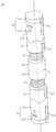
图1是本发明一实施例的储物装置的结构图,其中示意了储物装置处于容纳腔三分区时的状态;FIG. 1 is a structural diagram of a storage device according to an embodiment of the present invention, wherein the storage device is shown in a state when the storage device is in three partitions of an accommodating cavity;

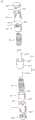
图2是本发明一实施例的储物装置的结构爆炸图;2 is a structural exploded view of a storage device according to an embodiment of the present invention;

图3是本发明一实施例的导向件的结构示意图;3 is a schematic structural diagram of a guide according to an embodiment of the present invention;

图4是本发明一实施例的导向机构与第一分隔架相配合的局部示意图;FIG. 4 is a partial schematic view of the matching of the guide mechanism and the first partition frame according to an embodiment of the present invention;

图5是本发明一实施例的导向件与第一分隔架相配合的局部前视图;FIG. 5 is a partial front view of the guide member in cooperation with the first partition frame according to an embodiment of the present invention;

图6是本发明一实施例的调节组件的结构示意图,其中示意了调节组件处于啮合状态;6 is a schematic structural diagram of an adjustment assembly according to an embodiment of the present invention, wherein the adjustment assembly is shown in an engaged state;

图7是本发明一实施例的调节组件的结构爆炸图。FIG. 7 is an exploded view of the structure of the adjusting assembly according to an embodiment of the present invention.

具体实施方式Detailed ways

本发明一实施方式提供了一种冰箱,所述冰箱包括箱体和箱门,所述箱体和箱门限定出至少一个存储间室,所述存储间室可以为冷藏室、冷冻室、变温室等。所述冰箱还包括用于储存物品的储物装置,所述储物装置设置于所述存储间室内,其具体可设置为抽屉、保鲜盒、储物箱、瓶座等。下面,结合具体实施例对本发明的所述储物装置进行详细介绍。An embodiment of the present invention provides a refrigerator, the refrigerator includes a box body and a box door, the box body and the box door define at least one storage compartment, and the storage compartment may be a refrigerator compartment, a freezer compartment, Greenhouse etc. The refrigerator further includes a storage device for storing items, the storage device is arranged in the storage compartment, and can be specifically configured as a drawer, a fresh-keeping box, a storage box, a bottle holder, and the like. Hereinafter, the storage device of the present invention will be described in detail with reference to specific embodiments.

参图1~7,本实施例提供了一种储物装置100,该储物装置100包括本体10、一对导向机构20、第一分隔架30、第二分隔架40以及具有至少两组调节机构的调节组件50。1 to 7 , the present embodiment provides astorage device 100 , thestorage device 100 includes a main body 10 , a pair of guide mechanisms 20 , afirst divider 30 , asecond divider 40 and at least two sets ofadjustment Adjustment assembly 50 of the mechanism.

本体10围成具有上开口的大致呈长方体的容纳腔101,该容纳腔101用于储存各类储存物,如食品、饮料等。本体10包括底壁、相对设置的一对第一侧壁11以及相对设置的一对第二侧壁12。所述底壁用于承载储存物,一对第一侧壁11和一对第二侧壁12分别自所述底壁向上垂直延伸。The body 10 encloses a substantially rectangular parallelepipedaccommodating cavity 101 with an upper opening, and theaccommodating cavity 101 is used to store various storage items, such as food and beverages. The body 10 includes a bottom wall, a pair offirst side walls 11 arranged oppositely, and a pair ofsecond side walls 12 arranged oppositely. The bottom wall is used to carry storage, and a pair offirst side walls 11 and a pair ofsecond side walls 12 extend vertically upward from the bottom wall, respectively.

为清楚地表达本实施例中所描述的位置与方向,一对第一侧壁11的相对位置所限定的方向定义为前后方向(也称为纵向),一对第二侧壁12的相对位置所限定的方向定义为左右方向(也称为横向)。也即,一对第一侧壁11前后相对设置,一对第二侧壁12左右相对设置。另外,所述前后方向和所述左右方向共同限定的平面定义为水平面,垂直于所述水平面的方向定义为竖直方向。In order to clearly express the positions and directions described in this embodiment, the direction defined by the relative positions of the pair offirst side walls 11 is defined as the front-rear direction (also referred to as the longitudinal direction), and the relative positions of the pair ofsecond side walls 12 The defined direction is defined as the left-right direction (also referred to as the lateral direction). That is, the pair offirst side walls 11 are arranged opposite to each other in front and rear, and the pair ofsecond side walls 12 are arranged opposite to left and right. In addition, a plane jointly defined by the front-rear direction and the left-right direction is defined as a horizontal plane, and a direction perpendicular to the horizontal plane is defined as a vertical direction.

参图1~2,一对导向机构20分别设置于一对第二侧壁12处。导向机构20包括导向杆21、导向件22以及固定座23,其中:导向机构20通过固定座23固定于本体10上,固定座23与本体10之间的固定方式可采用螺纹连接、铆接、卡扣连接等;导向杆21平行于第二侧壁12并前后延伸;导向件22套设于导向杆21上并可沿导向杆21前后滑动。Referring to FIGS. 1-2 , a pair of guide mechanisms 20 are respectively disposed at a pair ofsecond side walls 12 . The guide mechanism 20 includes aguide rod 21 , aguide member 22 and a fixedseat 23 , wherein: the guide mechanism 20 is fixed on the body 10 through thefixed seat 23 , and the fixing method between thefixed seat 23 and the body 10 can be screwed, riveted, or clamped. Theguide rod 21 is parallel to thesecond side wall 12 and extends back and forth; theguide piece 22 is sleeved on theguide rod 21 and can slide back and forth along theguide rod 21 .

参图3~4,在本实施例中,导向杆21设置为圆柱形长杆;导向件22包括导向本体220和分别具有圆柱形通孔222的一对悬臂221,导向件22通过通孔222套设于导向杆21上并可沿导向杆21前后滑动。3 to 4 , in this embodiment, theguide rod 21 is configured as a long cylindrical rod; theguide member 22 includes aguide body 220 and a pair ofcantilever arms 221 having cylindrical throughholes 222 respectively, and theguide member 22 passes through the throughholes 222 It is sleeved on theguide rod 21 and can slide back and forth along theguide rod 21 .

优选地,通孔222的直径略小于导向杆21的直径,当导向件22套设于导向杆21上时,导向件22不仅于导向杆21上沿图示x1方向前后滑动,还可沿图示x2方向绕导向杆21的轴心线圆周转动以及沿图示x3方向相对导向杆21径向晃动。这样,可避免导向件22与导向杆21之间的卡滞现象的发生。Preferably, the diameter of thethrough hole 222 is slightly smaller than the diameter of theguide rod 21. When theguide member 22 is sleeved on theguide rod 21, theguide member 22 not only slides back and forth on theguide rod 21 in the direction x1 shown in the figure, but also slides along the direction of x1 shown in the figure. The direction of x2 shown in the figure is rotated around the axis of theguide rod 21 and the direction of the shown x3 is radially swayed relative to theguide rod 21. In this way, the occurrence of jamming between theguide member 22 and theguide rod 21 can be avoided.

进一步地,第一分隔架30容置于容纳腔101内,并可用于对容纳腔101进行前后分割。具体地,第一分隔架30包括分隔本体31,分隔本体31横置于容纳腔101内以用于对容纳腔101进行分割,分隔本体31所在的竖直面定义第一分隔架30的分隔面,容纳腔101以第一分隔架30的分隔面为界被前后分割。在本实施例中,分隔本体31包括垂直于前后方向且共平面设置的分隔板311、312,优选地分隔板311、312设置为玻璃板,这样,不仅可实现对容纳腔101进行前后分割,而且可避免容纳腔101被前后分割形成的储存分区之间的物品的交叉滑落。当然,在变化的实施例中,分隔本体31还可设置为呈格栅状排布的分隔杆结构或者设置为同时包括分隔杆结构和分隔板311、312。Further, thefirst partition frame 30 is accommodated in theaccommodating cavity 101 and can be used to divide theaccommodating cavity 101 back and forth. Specifically, thefirst partition frame 30 includes apartition body 31 , thepartition body 31 is transversely disposed in theaccommodating cavity 101 for dividing theaccommodating cavity 101 , and the vertical plane where thepartition body 31 is located defines the partition surface of thefirst partition frame 30 , theaccommodating cavity 101 is divided back and forth with the partition surface of thefirst partition frame 30 as a boundary. In this embodiment, thepartition body 31 includes partition plates 311 and 312 that are perpendicular to the front-rear direction and are coplanarly arranged. Preferably, the partition plates 311 and 312 are glass plates. It can be divided, and the cross sliding of the articles between the storage areas formed by the front and rear divisions of theaccommodating cavity 101 can be avoided. Of course, in a modified embodiment, thepartition body 31 may also be configured as a partition bar structure arranged in a grid shape or configured to include both the partition bar structure and the partition plates 311 and 312 .

进一步地,参图2,第一分隔架30通过导向机构20前后滑动地连接至本体10上,以调整容纳腔101被前后分割形成的储存分区的大小和/或数量。具体地,第一分隔架30包括形成于第一分隔架30的左右两端的一对第一连接件33,每个第一连接件33连接至相对应的导向件22上。当导向件22沿导向杆21前后滑动时,第一分隔架30同步的于容纳腔101内前后滑动。Further, referring to FIG. 2 , thefirst partition frame 30 is slidably connected to the main body 10 through the guide mechanism 20 , so as to adjust the size and/or quantity of the storage partitions formed by the front and rear divisions of theaccommodating cavity 101 . Specifically, the first dividingframe 30 includes a pair of first connecting pieces 33 formed at the left and right ends of the first dividingframe 30 , and each first connecting piece 33 is connected to the corresponding guidingpiece 22 . When theguide member 22 slides back and forth along theguide rod 21 , thefirst partition frame 30 slides back and forth in theaccommodating cavity 101 synchronously.

第一连接件33包括固定件331和连接杆332。其中,固定件331的内端部通过铆接或卡扣等方式与分隔本体31固定连接;连接杆332沿前后方向延伸,且连接杆332的中部固定连接于固定件331外端部,也即,连接杆332的两端部分别自固定件331向前、向后延伸。The first connecting member 33 includes a fixingmember 331 and a connectingrod 332 . The inner end of the fixingmember 331 is fixedly connected to thepartition body 31 by means of riveting or snapping; the connectingrod 332 extends in the front-rear direction, and the middle portion of the connectingrod 332 is fixedly connected to the outer end of the fixingmember 331, that is, Two ends of the connectingrod 332 extend forward and backward respectively from the fixingmember 331 .

相对应的,参图3~5,导向件22包括向下延伸出导向本体220的卡钩223、安装槽224、限位部225以及开口226。其中,安装槽224由卡钩223围成并前后延伸;开口226为形成于卡钩223与导向本体220之间的狭缝,其连通外界与安装槽224;限位部225为自开口226处凹设于卡钩223上的U形缺口。Correspondingly, referring to FIGS. 3 to 5 , theguide member 22 includes ahook 223 extending downward from theguide body 220 , aninstallation groove 224 , a limitingportion 225 and anopening 226 . Theinstallation slot 224 is surrounded by thehook 223 and extends forward and backward; theopening 226 is a slit formed between thehook 223 and theguide body 220 , which communicates with the outside world and theinstallation slot 224 ; the limitingportion 225 is formed from theopening 226 The U-shaped notch is recessed on thehook 223 .

在第一连接件33与导向件22的连接状态下,连接杆332可通过开口226沿第一方向挂扣于安装槽224内,所述第一方向垂直于前后方向,在本实施例中,所述第一方向为斜向外下方;限位部225与固定件331匹配对接,具体地,当连接杆332挂扣于安装槽224内时,固定件331配合至所述限位部225内并被所述限位部225的前后侧面所抵持,以限制第一连接件33相对导向件22前后运动,进而实现第一分隔架30沿前后方向同步滑动地连接至导向件22上。In the connection state of the first connecting member 33 and the guidingmember 22, the connectingrod 332 can be hooked into theinstallation groove 224 in the first direction through theopening 226, and the first direction is perpendicular to the front-rear direction. In this embodiment, The first direction is obliquely outward and downward; the limitingportion 225 is matched with the fixingmember 331 . Specifically, when the connectingrod 332 is hooked into the mountinggroove 224 , the fixingmember 331 is fitted into the limitingportion 225 It is resisted by the front and rear sides of the limitingportion 225 to restrict the front and rear movement of the first connecting member 33 relative to theguide member 22 , thereby realizing the synchronous sliding connection of thefirst partition frame 30 to theguide member 22 in the front-rear direction.

参图5,进一步地,导向件22还具有设置于开口226处的引导斜面227,以便于引导连接杆332顺利通过开口226挂扣于安装槽224内。Referring to FIG. 5 , further, theguide member 22 further has aguide slope 227 disposed at theopening 226 , so as to guide the connectingrod 332 to smoothly pass through theopening 226 and be hooked into theinstallation groove 224 .

在本实施例中,卡钩223设置为弹性结构;连接杆332设置为具有直径D的圆柱形杆,在沿所述第一方向上,开口226的口径逐渐减小至最小值W,其中W<D。这样,当连接杆332通过开口226向安装槽224内配接时,卡钩223在连接杆332的抵持下发生弹性形变,直至连接杆332配合至安装槽224内后,在卡钩223的自身弹性恢复力作用下,连接杆332被稳定地保持在安装槽224内。In this embodiment, thehook 223 is set as an elastic structure; the connectingrod 332 is set as a cylindrical rod with a diameter D, and along the first direction, the diameter of theopening 226 is gradually reduced to a minimum value W, where W <D. In this way, when the connectingrod 332 is fitted into theinstallation groove 224 through theopening 226, thehook 223 is elastically deformed under the resistance of the connectingrod 332 until the connectingrod 332 is fitted into theinstallation groove 224, and thehook 223 is Under the action of its own elastic restoring force, the connectingrod 332 is stably held in theinstallation groove 224 .

另外,参图1和2,在本实施例中,导向机构20设置于本体10背离容纳腔101的外部,每个第二侧壁12上设置有前后延伸的导槽13,第一分隔架30的左右两端穿过导槽13后配接至导向机构20上,也即,第一连接件33至少部分自容纳腔101穿过导槽13后配接于导向件22上。In addition, referring to FIGS. 1 and 2 , in this embodiment, the guide mechanism 20 is provided on the outside of the main body 10 away from theaccommodating cavity 101 , eachsecond side wall 12 is provided with aguide groove 13 extending back and forth, and thefirst partition 30 The left and right ends of the first connecting member 33 pass through theguide groove 13 and then are connected to the guide mechanism 20 , that is, the first connecting member 33 at least partially passes through theguide groove 13 from theaccommodating cavity 101 and is connected to theguide member 22 .

进一步地,参图1~2,第二分隔架40容置于容纳腔101内,并可用于对容纳腔101进行左右分割。具体地,第二分隔架40包括分隔本体41,分隔本体41可用于对容纳腔101进行分割,分隔本体41所在的竖直平面定义第二分隔架40的分隔面。在本实施例中,分隔本体41设置为垂直于水平方向放置的玻璃隔板,这样,不仅可实现对容纳腔101进行分割,而且可避免容纳腔101被第二分隔架40分割形成的储存分区之间的物品的交叉滑落。当然,在变化的实施例中,分隔本体41还可设置为呈格栅状排布的分隔杆结构或者设置为同时包括分隔杆结构和玻璃隔板。Further, referring to FIGS. 1-2 , thesecond partition frame 40 is accommodated in theaccommodating cavity 101 and can be used to divide theaccommodating cavity 101 from left to right. Specifically, thesecond partition frame 40 includes a partition body 41 , the partition body 41 can be used to divide theaccommodating cavity 101 , and the vertical plane where the partition body 41 is located defines a partition surface of thesecond partition frame 40 . In this embodiment, the partition body 41 is set as a glass partition placed perpendicular to the horizontal direction, so that not only can theaccommodating cavity 101 be divided, but also a storage partition formed by dividing theaccommodating cavity 101 by thesecond partition frame 40 can be avoided The cross between the items slips off. Of course, in a modified embodiment, the partition body 41 can also be configured as a partition rod structure arranged in a grid shape or configured to include a partition rod structure and a glass partition at the same time.

进一步地,第二分隔架40通过所述调节机构绕竖直轴t转动地连接于第一分隔架30上,在第二分隔架40的转动路径内,参图1,第二分隔架40相对第一分隔架30具有叠置状态和展开状态:当第二分隔架40处于所述叠置状态时,第二分隔架40的分隔面与第一分隔架30的分隔面相平行,第二分隔架40的分隔本体41紧密贴靠于第一分隔架30的分隔本体31;当第二分隔架40处于所述展开状态时,第二分隔架40的分隔面与第一分隔架30的分隔面具有一非零夹角,在本实施例中,此时第二分隔架40的分隔面与第一分隔架30的分隔面相垂直,也即,第二分隔架40的分隔本体41大致垂直于第一分隔架30的分隔本体31,容纳腔101可以以第一分隔架30的分隔面为界被前后分割,且容纳腔101可以以第二分隔架40的分隔面为界被左右分割。Further, thesecond divider 40 is rotatably connected to thefirst divider 30 through the adjusting mechanism around the vertical axis t. In the rotation path of thesecond divider 40, referring to FIG. 1, thesecond divider 40 is opposite to Thefirst divider 30 has an overlapped state and an unfolded state: when thesecond divider 40 is in the overlapped state, the partition surface of thesecond divider 40 is parallel to the partition surface of thefirst divider 30, and the second divider The partition body 41 of 40 is closely abutted to thepartition body 31 of thefirst partition rack 30; when thesecond partition rack 40 is in the unfolded state, the partition surface of thesecond partition rack 40 and the partition surface of thefirst partition rack 30 have A non-zero included angle, in this embodiment, the partition surface of thesecond partition frame 40 is perpendicular to the partition surface of thefirst partition frame 30, that is, the partition body 41 of thesecond partition frame 40 is substantially perpendicular to thefirst partition frame 30. In thepartition body 31 of thepartition rack 30 , theaccommodating cavity 101 can be divided front and rear with the partition plane of thefirst partition rack 30 as the boundary, and theaccommodating cavity 101 can be divided left and right with the partition plane of thesecond partition rack 40 as the boundary.

下面参图6~7,对调节组件50的具体结构进行详细说明。6-7, the specific structure of theadjustment assembly 50 will be described in detail.

首先,对每组所述调节机构进行说明。在本实施例中,调节组件50的每组所述调节机构设置为圆柱形结构,其几何中轴线确定所述竖直轴t,每组所述调节机构包括第一调节件51、第二调节件52、弹性件53及限位件54。First, each group of the adjustment mechanisms will be described. In this embodiment, each group of the adjustment mechanisms of theadjustment assembly 50 is configured as a cylindrical structure, the geometric center axis of which defines the vertical axis t, and each group of the adjustment mechanisms includes afirst adjustment member 51, a secondadjustment member component 52 ,elastic component 53 and limitingcomponent 54 .

第一调节件51配接至第一分隔架30,且在所述竖直轴t的圆周方向上,第一调节件51与第一分隔架30相对固定,也即第一调节件51和第一分隔架30无法绕所述竖直轴t相对彼此转动。具体地,参图2,第一分隔架30包括第二连接件32,第二连接件32通过螺纹、卡扣等方式固定连接于第一分隔架30的分隔本体31上;第二连接件32具有空腔320以及凹槽322。相对应的,参图6,第一调节件51与第二连接件32套接配合,其配合于第二连接件32的空腔320内;第一调节件51包括形成于其外壁上的凸柱513,凸柱513与凹槽322卡持配接,从而限制第一调节件51和第一分隔架30绕所述竖直轴t相对彼此转动。在变化的实施例中,凸柱513和凹槽322位置可互换。The first adjustingmember 51 is matched to thefirst dividing frame 30, and in the circumferential direction of the vertical axis t, the first adjustingmember 51 is relatively fixed to thefirst dividing frame 30, that is, the first adjustingmember 51 and thefirst dividing frame 30 are relatively fixed. Adivider 30 cannot rotate relative to each other about said vertical axis t. Specifically, referring to FIG. 2 , thefirst partition frame 30 includes a second connecting member 32 , and the second connecting member 32 is fixedly connected to thepartition body 31 of thefirst partition frame 30 by means of threads, snaps, etc.; the second connecting member 32 It has a cavity 320 and agroove 322 . Correspondingly, referring to FIG. 6 , the first adjustingmember 51 is sleeved with the second connecting member 32 , which fits in the cavity 320 of the second connecting member 32 ; the first adjustingmember 51 includes a protrusion formed on the outer wall thereof. Theposts 513 and the protrudingposts 513 are engaged with thegrooves 322 so as to restrict the rotation of the first adjustingmember 51 and thefirst dividing frame 30 relative to each other around the vertical axis t. In a variant embodiment, the positions of theposts 513 and thegrooves 322 may be interchanged.

第二调节件52配接至第二分隔架40,且在所述竖直轴t的圆周方向上,第二调节件52与第二分隔架40相对固定,也即第二调节件52和第二分隔架40无法绕所述竖直轴t相对彼此转动。具体地,参图2,第二分隔架40包括第三连接件42,第三连接件42通过螺纹、卡扣等方式固定连接于第二分隔架40的分隔本体41的一端上;第三连接件42具有空腔420以及凹槽421。相对应的,参图6,第二调节件52与第三连接件42套接配合,其配合于第三连接件42的空腔420内;第二调节件52包括形成于其外壁上的凸柱521,凸柱521与凹槽421卡持配接,从而限制第二调节件52和第二分隔架40绕所述竖直轴t相对彼此转动。在变化的实施例中,凸柱521和凹槽421位置可互换。Thesecond adjusting member 52 is matched to thesecond dividing frame 40, and in the circumferential direction of the vertical axis t, the second adjustingmember 52 is relatively fixed with thesecond dividing frame 40, that is, the second adjustingmember 52 and thesecond dividing frame 40 are relatively fixed. The twodividers 40 cannot rotate relative to each other about the vertical axis t. Specifically, referring to FIG. 2 , thesecond divider 40 includes a third connector 42 , and the third connector 42 is fixedly connected to one end of the dividing body 41 of thesecond divider 40 by means of threads, snaps, etc.; the third connection The piece 42 has a cavity 420 and a groove 421 . Correspondingly, referring to FIG. 6 , the second adjustingmember 52 is sleeved with the third connecting member 42 , which fits in the cavity 420 of the third connecting member 42 ; the second adjustingmember 52 includes a protrusion formed on the outer wall thereof. Thepost 521, the protrudingpost 521 and the groove 421 are engaged with each other, so as to restrict the rotation of the second adjustingmember 52 and thesecond dividing frame 40 relative to each other around the vertical axis t. In a variant embodiment, the positions of theposts 521 and the grooves 421 may be interchanged.

而且,第二调节件52可相对第一调节件51绕所述竖直轴t转动。这样,在使用时,当用户施加外力于第二分隔架40上时,第二分隔架40可带动第二调节件52同步绕所述竖直轴t转动,而第一调节件51和第一分隔架30保持相对静止,从而实现第二分隔架40相对第一分隔架30绕所述竖直轴t的转动,进而实现第二分隔架40于所述叠置状态和所述展开状态间切换。Moreover, the second adjustingmember 52 can rotate relative to the first adjustingmember 51 around the vertical axis t. In this way, during use, when the user exerts an external force on thesecond partition frame 40, thesecond partition frame 40 can drive thesecond adjustment member 52 to rotate around the vertical axis t synchronously, and thefirst adjustment member 51 and the first Thedivider 30 remains relatively static, so that thesecond divider 40 can rotate relative to thefirst divider 30 around the vertical axis t, thereby realizing the switching of thesecond divider 40 between the stacked state and the unfolded state .

限位件54连接至第一调节件51,在所述竖直轴t的轴向(也即竖直方向)上,限位件54与第一调节件51之间的相对位移被至少部分地限制。在本实施例中,限位件54与第一调节件51之间的相对位移被完全限制,也即限位件54沿所述轴向相对固定地连接于第一调节件51上。The limitingmember 54 is connected to the first adjustingmember 51, and the relative displacement between the limitingmember 54 and the first adjustingmember 51 in the axial direction (ie vertical direction) of the vertical axis t is at least partially limit. In this embodiment, the relative displacement between the limitingmember 54 and the first adjustingmember 51 is completely restricted, that is, the limitingmember 54 is relatively fixedly connected to the first adjustingmember 51 along the axial direction.

第二调节件52设置于第一调节件51与限位件54之间。弹性件53位于第二调节件52和限位件54之间,具体地,第二调节件52上具有第一抵持面,限位件54上具有第二抵持面,弹性件53位于第二调节件52的所述第一抵持面和限位件54的所述第二抵持面之间。Thesecond regulating member 52 is disposed between the first regulatingmember 51 and the limitingmember 54 . Theelastic member 53 is located between the second adjustingmember 52 and the limitingmember 54 . Specifically, the second adjustingmember 52 has a first abutting surface, the limitingmember 54 has a second abutting surface, and theelastic member 53 is located on the first abutting surface. Between the first abutting surface of the two adjustingmembers 52 and the second abutting surface of the limitingmember 54 .

第一调节件51包括形成于其一端面的整周波浪形的第一凹凸曲面514,第二调节件52包括形成于其一端面的整周波浪形的第二凹凸曲面522,第一凹凸曲面514和第二凹凸曲面522相匹配。The first adjustingmember 51 includes a first concave-convexcurved surface 514 formed on an entire circumference of one end face, and the second adjustingmember 52 includes a second concave-convexcurved surface 522 formed on an entire circumference of one end surface of the concave-convex curved surface. 514 and the second concave-convexcurved surface 522 are matched.

在第二调节件52绕所述竖直轴t相对第一调节件51转动的过程中,第一凹凸曲面514和第二凹凸曲面522可彼此啮合或抵接,以使第二调节件52在所述轴向上相对第一调节件51作远离或靠近的往复跳跃式运动;并且,当第二调节件52在所述轴向上相对第一调节件51远离时,第二调节件52和限位件54在所述轴向上相对靠近,弹性件53被第二调节件52的所述第一抵持面和限位件54的所述第二抵持面夹持并发生压缩形变,这样,在弹性件53的自身弹性恢复力作用下,使第一凹凸曲面514和第二凹凸曲面522始终相接触,进而完成第二调节件52与第一调节件51在所述轴向上相对靠近或远离的过程。During the rotation of the second adjustingmember 52 relative to the first adjustingmember 51 around the vertical axis t, the first concave-convexcurved surface 514 and the second concave-convexcurved surface 522 can engage or abut with each other, so that the second adjustingmember 52 is in the The axial direction relative to thefirst adjustment member 51 makes a reciprocating jumping movement away from or approaching; and, when thesecond adjustment member 52 moves away from thefirst adjustment member 51 in the axial direction, thesecond adjustment member 52 and The limitingmember 54 is relatively close to the axial direction, theelastic member 53 is clamped by the first abutting surface of the second adjustingmember 52 and the second abutting surface of the limitingmember 54 and undergoes compression deformation, In this way, under the action of the elastic restoring force of theelastic member 53, the first concave-convexcurved surface 514 and the second concave-convexcurved surface 522 are always in contact with each other, thereby completing the axial direction of the second regulatingmember 52 and the first regulatingmember 51. The process of approaching or moving away.

进一步地,所述调节机构具有第一凹凸曲面514和第二凹凸曲面522彼此凹凸配合的至少两个啮合状态以及第一凹凸曲面514和第二凹凸曲面522彼此凸凸抵接的抵接状态。Further, the adjustment mechanism has at least two meshing states in which the first concave-convexcurved surface 514 and the second concave-convexcurved surface 522 are in concave-convex engagement with each other, and an abutting state in which the first concave-convexcurved surface 514 and the second concave-convexcurved surface 522 abut each other convexly and convexly.

当所述调节机构处于所述啮合状态时,第一调节件51与第二调节件52之间沿所述轴向上的距离最小;当所述调节机构由所述啮合状态向所述抵接状态运动时,第一调节件51与第二调节件52相对彼此沿所述轴向远离,且第二调节件52的所述第一抵持面和限位件54的所述第二抵持面在所述轴向上相对靠近,弹性件53逐渐被压缩且弹性形变量逐渐增大;当所述调节机构处于所述抵接状态时,第一调节件51与第二调节件52之间沿所述轴向上的距离最大,且第二调节件52的所述第一抵持面和限位件54的所述第二抵持面在所述轴向上的距离最小,弹性件53的弹性形变量达到极大值;当所述调节机构由所述抵接状态向所述啮合状态运动时,弹性件53在自身形变恢复力作用下驱动第一调节件51与第二调节件52相对彼此沿所述轴向靠近。When the adjustment mechanism is in the engaged state, the distance between thefirst adjustment member 51 and thesecond adjustment member 52 along the axial direction is the smallest; when the adjustment mechanism is in the engagement state to the abutment When the state is in motion, the first adjustingmember 51 and the second adjustingmember 52 move away from each other in the axial direction, and the first abutting surface of the second adjustingmember 52 and the second abutting surface of the limitingmember 54 abut against each other. When the surfaces are relatively close to each other in the axial direction, theelastic member 53 is gradually compressed and the amount of elastic deformation gradually increases; when the adjusting mechanism is in the abutting state, between the first adjustingmember 51 and the second adjustingmember 52 The distance along the axial direction is the largest, and the distance between the first abutting surface of the second adjustingmember 52 and the second abutting surface of the limitingmember 54 in the axial direction is the smallest, and theelastic member 53 When the adjusting mechanism moves from the abutting state to the meshing state, theelastic member 53 drives the first adjustingmember 51 and the second adjustingmember 52 under the action of its own deformation restoring force are approached in the axial direction relative to each other.

在本实施例中,当所述调节机构未处于所述啮合状态时,弹性件53在其自身弹性恢复力作用下始终施加于第二调节件52上一驱动力,该驱动力的方向平行于所述轴向并驱使第二调节件52具有趋近第一调节件51的运动趋势,以使所述调节机构恢复至所述啮合状态。In this embodiment, when the adjusting mechanism is not in the engaging state, theelastic member 53 always exerts a driving force on the second adjustingmember 52 under the action of its own elastic restoring force, and the direction of the driving force is parallel to The axial direction drives the second adjustingmember 52 to have a moving tendency to approach the first adjustingmember 51 , so that the adjusting mechanism returns to the engaging state.

并且,第二分隔架40的所述叠置状态与所述调节机构的一所述啮合状态相对应,第二分隔架40的所述展开状态与所述调节机构的另一所述啮合状态相对应。In addition, the stacked state of thesecond partition frame 40 corresponds to one of the meshed states of the adjustment mechanism, and the unfolded state of thesecond partition frame 40 corresponds to the other meshed state of the adjustment mechanism. correspond.

这样,以由所述叠置状态变化至所述展开状态的过程(由所述展开状态变化至所述叠置状态的过程与之相反,不再赘述)为例,对第二分隔架40的转动过程进行详述:In this way, taking the process of changing from the stacked state to the unfolded state (the process of changing from the unfolded state to the stacked state is the opposite, and will not be repeated) as an example, the process of thesecond partition frame 40 is The rotation process is described in detail:

当第二分隔架40处于所述叠置状态时,人为外力推动第二分隔架40相对第一分隔架30绕竖直轴t转动,同步地第二调节件52相对第一调节件51绕所述竖直轴t转动,所述调节机构由一所述啮合状态向所述抵接状态变化,第二调节件52沿所述轴向远离第一调节件51,且弹性件53被压缩形变;When thesecond divider 40 is in the stacked state, thesecond divider 40 is pushed by an external force to rotate relative to thefirst divider 30 around the vertical axis t, and the second adjustingmember 52 rotates relative to the first adjustingmember 51 synchronously. When the vertical axis t rotates, the adjusting mechanism changes from the meshing state to the abutting state, the second adjustingmember 52 moves away from the first adjustingmember 51 along the axial direction, and theelastic member 53 is compressed and deformed;

随着第二调节件52的转动,当所述调节机构处于所述抵接状态时,弹性件53在其自身弹性恢复力作用下驱使第二调节件52继续自动转动,以使所述调节机构由所述抵接状态变化为另一所述啮合状态,进而第二分隔架40转动至所述展开状态,整个调节过程稳定且省力。With the rotation of the second adjustingmember 52, when the adjusting mechanism is in the abutting state, theelastic member 53 drives the second adjustingmember 52 to continue to rotate automatically under the action of its own elastic restoring force, so that the adjusting mechanism From the abutting state to another engaging state, and then thesecond dividing frame 40 rotates to the unfolding state, the entire adjustment process is stable and labor-saving.

进一步地,第二分隔架40于所述叠置状态和所述展开状态间切换时,第二分隔架40绕所述竖直轴t大致上转动角度为90°。相应的,第一凹凸曲面514和第二凹凸曲面522均设置为圆周四等分结构,也即所述调节机构由一所述啮合状态变换为所述抵接状态、再由该抵接状态变换为另一所述啮合状态时,第一调节件51绕所述竖直轴t相对第二调节件52依次转动45°、再转动45°(共计转动90°)。在变化的实施例中,还可依照第二分隔架40于所述叠置状态和所述展开状态间切换时的转动角度的具体需求,第一凹凸曲面514和第二凹凸曲面522相应设置为圆周不等分结构或者设置为圆周多等分结构(如三等分、五等分、六等分、八等分等)。Further, when thesecond divider 40 is switched between the stacked state and the unfolded state, thesecond divider 40 rotates at an angle of approximately 90° around the vertical axis t. Correspondingly, the first concave-convexcurved surface 514 and the second concave-convexcurved surface 522 are both set to have a four-circle bisector structure, that is, the adjustment mechanism is transformed from the meshing state to the abutting state, and then from the abutting state. When changing to another engagement state, the first adjustingmember 51 rotates 45° and then 45° in turn relative to the second adjustingmember 52 around the vertical axis t (a total of 90°). In a variant embodiment, the first concave-convexcurved surface 514 and the second concave-convexcurved surface 522 can be correspondingly set according to the specific requirements of the rotation angle of thesecond partition frame 40 when switching between the stacked state and the unfolded state. The circle is not equally divided into a structure or is set as a multi-division structure of the circle (such as three equal parts, five equal parts, six equal parts, eight equal parts, etc.).

进一步地,第一调节件51在所述轴向上与第一分隔架30相对固定的连接。具体地,第一调节件51包括定位销孔510,第一分隔架30的第二连接件32设置有配合销孔321,定位销孔510和配合销孔321可均与定位销(图未示)配合连接,以限制第一调节件51在所述轴向上与第一分隔架30相对运动,从而避免所述调节机构从第一分隔架30上向下脱落或向上突出。Further, the first adjustingmember 51 is relatively fixedly connected to thefirst dividing frame 30 in the axial direction. Specifically, the first adjustingmember 51 includes apositioning pin hole 510 , the second connecting member 32 of thefirst partition frame 30 is provided with a matching pin hole 321 , and thepositioning pin hole 510 and the matching pin hole 321 can both be connected with the positioning pin (not shown in the figure). ) is matched and connected to limit the relative movement of the first adjustingmember 51 and thefirst dividing frame 30 in the axial direction, so as to prevent the adjusting mechanism from falling off or protruding upward from thefirst dividing frame 30 .

进一步地,所述调节机构包括中转轴542,中转轴542设置为沿所述轴向延伸的圆柱体;第二调节件52具有中部圆柱形通孔523并通过所述通孔523套设于中转轴542上,以实现第二调节件52可于所述中转轴542上沿所述轴向滑动并绕所述竖直轴t转动。Further, the adjustment mechanism includes anintermediate shaft 542, and theintermediate shaft 542 is configured as a cylindrical body extending along the axial direction; thesecond adjustment member 52 has a central cylindrical throughhole 523 and is sleeved in the middle through the throughhole 523 On therotating shaft 542, so that the second adjustingmember 52 can slide on theintermediate shaft 542 along the axial direction and rotate around the vertical axis t.

在本实施例中,中转轴542设置于限位件54上,换句话说也即,限位件54包括具有所述第二抵持面的外套筒541以及沿所述轴向延伸出所述外套筒541的中转轴542,弹性件53和第二调节件52依次套设于中转轴542上,中转轴542的端部连接至第一调节件51。在变化的实施例中,中转轴542还可设置于第一调节件51上。In this embodiment, theintermediate shaft 542 is disposed on the limitingmember 54 , in other words, the limitingmember 54 includes anouter sleeve 541 having the second abutting surface and anouter sleeve 541 extending along the axial direction. Theintermediate shaft 542 of theouter sleeve 541 , theelastic member 53 and thesecond adjustment member 52 are sequentially sleeved on theintermediate shaft 542 , and the end of theintermediate shaft 542 is connected to thefirst adjustment member 51 . In a modified embodiment, theintermediate shaft 542 may also be disposed on the first adjustingmember 51 .

在本实施例中,第一调节件51包括彼此卡扣配接的端盖511和组装构件512。其中,端盖511具有封闭的端面,从而增加美观并防止异物掉落至调节组件50内部而造成污染,端盖511包括两个卡钩5111;组装构件512包括两个卡槽5121;两个卡钩5111与两个卡槽5121一一对应并卡扣配接,以使端盖511和组装构件512彼此组装配接。在变化的实施例中,卡钩5111和卡槽5121的位置可互换。In this embodiment, the first adjustingmember 51 includes anend cover 511 and an assemblingmember 512 that are snap-fitted to each other. Theend cover 511 has a closed end surface, so as to enhance the appearance and prevent foreign objects from falling into theadjustment assembly 50 to cause pollution. Theend cover 511 includes twohooks 5111; Thehooks 5111 are in one-to-one correspondence with the two lockinggrooves 5121 and are snap-fitted, so that theend cover 511 and the assemblingmember 512 are assembled and assembled with each other. In a variant embodiment, the positions of thehook 5111 and theslot 5121 can be interchanged.

第一凹凸曲面514形成于组装构件512背离端盖511的一端面上。The first concave-convexcurved surface 514 is formed on an end surface of theassembly member 512 facing away from theend cap 511 .

另外,进一步地,在本实施例中,储物装置100包括两个第二分隔架40,两个第二分隔架40分立于第一分隔架30的前后两侧;相应的,参图6~7,调节组件50包括两组所述调节机构,每组所述调节机构与一第二分隔架40相适配。每个第二分隔架40通过相对应的所述调节机构独立地绕竖直轴t转动地连接至第一分隔架30上:如图1所示,一第二分隔架40处于所述叠置状态,另一第二分隔架40处于所述展开状态。这样可实现容纳腔101被分割的多样化,例如:两个第二分隔架40均处于所述叠置状态而通过滑动第一分隔架30,实现容纳腔101零分区和二分区;或者,如图1所示,实现容纳腔101三分区;或者两个第二分隔架40均处于所述展开状态,实现容纳腔101四分区。In addition, further, in this embodiment, thestorage device 100 includes twosecond dividers 40, and the twosecond dividers 40 are separated from the front and rear sides of thefirst divider 30; correspondingly, refer to FIGS. 6- 7. Theadjustment assembly 50 includes two sets of the adjustment mechanisms, and each group of the adjustment mechanisms is adapted to asecond partition frame 40 . Eachsecond divider 40 is independently rotatably connected to thefirst divider 30 around the vertical axis t through the corresponding adjustment mechanism: as shown in FIG. 1 , asecond divider 40 is in the stack state, the othersecond divider 40 is in the unfolded state. In this way, theaccommodating cavity 101 can be divided into diversification. For example, the twosecond partitions 40 are in the stacked state, and thefirst partition 30 is slid to realize zero partition and two partitions of theaccommodating cavity 101; or, as As shown in FIG. 1 , three partitions of theaccommodating cavity 101 are realized; or both of the second partition frames 40 are in the expanded state, so that four partitions of theaccommodating cavity 101 are realized.

具体地,在本实施例中,在两组所述调节机构中,一组所述调节机构的第二调节件52与第二分隔架40的其中之一配接,另一组所述调节机构的第二调节件52与第二分隔架40的其中另一配接。Specifically, in this embodiment, in the two sets of adjustment mechanisms, thesecond adjustment member 52 of one group of the adjustment mechanisms is matched with one of the second partition frames 40, and the other group of the adjustment mechanisms Thesecond adjusting member 52 is matched with the other one of the second partition frames 40 .

调节组件50设置为以平面q为对称面的镜面对称结构,该平面q与所述竖直轴t相垂直。进一步地,两组所述调节机构连体设置且以平面q为对称面的镜面对称设置。具体地,在本实施例中,两组所述调节机构通过限位件54一体连接,且各自的弹性件53、第二调节件52和第一调节件51沿所述轴向依次向上方、下方排布。当然,在变化的实施例中,两组所述调节机构还可设置为通过第一调节件51一体连接,且各自的第二调节件52、弹性件53和限位件54沿所述轴向依次向上方、下方排布。Theadjustment assembly 50 is set as a mirror-symmetric structure with a plane q as a plane of symmetry, and the plane q is perpendicular to the vertical axis t. Further, the two sets of adjustment mechanisms are arranged in one piece and are arranged in mirror symmetry with the plane q as the symmetry plane. Specifically, in this embodiment, the two sets of adjustment mechanisms are integrally connected by the limitingmember 54 , and the respectiveelastic member 53 , thesecond adjustment member 52 and thefirst adjustment member 51 are upward and downward in sequence along the axial direction. Arranged below. Of course, in a modified embodiment, the two sets of adjustment mechanisms can also be configured to be integrally connected through thefirst adjustment member 51, and the respectivesecond adjustment member 52,elastic member 53 and limitingmember 54 are along the axial direction. Arranged up and down in order.

与现有技术相比,本实施例的储物装置100,可按需调整容纳腔101分割形成的储物分区的数量/大小,灵活性高;而且第一分隔架30的拆卸组装方便,且使用过程中稳定性好;第一分隔架30分割形成的储物分区可避免交叉掉落。Compared with the prior art, thestorage device 100 of this embodiment can adjust the number/size of the storage partitions formed by dividing theaccommodating cavity 101 as needed, and has high flexibility; and the disassembly and assembly of thefirst partition frame 30 is convenient, and Good stability during use; the storage partitions formed by the division of thefirst partition frame 30 can avoid cross-dropping.

需要说明的是,本上述实施例中,限位件54与第一调节件51之间沿所述轴向的相对位移被完全限制。而在变化的实施例中,限位件54与第一调节件51之间的相对位移被部分限制,也即,限位件54可相对第一调节件51沿所述轴向定量地位移。具体地,限位件54沿所述轴向可相对第一调节件51运动且该相对运动的运动位移小于第二调节件52相对第一调节件51沿所述轴向的运动位移,从而实现当第二调节件52远离第一调节件51运动时,第二调节件52与限位件54之间的间距变小,进而使弹性件53可被压缩形变即可。It should be noted that, in the above embodiment, the relative displacement between the limitingmember 54 and the first adjustingmember 51 along the axial direction is completely restricted. In a modified embodiment, the relative displacement between the limitingmember 54 and the first adjustingmember 51 is partially limited, that is, the limitingmember 54 can be quantitatively displaced relative to the first adjustingmember 51 along the axial direction. Specifically, the limitingmember 54 can move relative to the first adjustingmember 51 in the axial direction, and the movement displacement of the relative movement is smaller than the moving displacement of the second adjustingmember 52 relative to the first adjustingmember 51 along the axial direction, so as to realize When the second adjustingmember 52 moves away from the first adjustingmember 51 , the distance between the second adjustingmember 52 and the limitingmember 54 is reduced, so that theelastic member 53 can be compressed and deformed.

应当理解,虽然本说明书按照实施方式加以描述,但并非每个实施方式仅包含一个独立的技术方案,说明书的这种叙述方式仅仅是为清楚起见,本领域技术人员应当将说明书作为一个整体,各实施方式中的技术方案也可以经适当组合,形成本领域技术人员可以理解的其他实施方式。It should be understood that although this specification is described in terms of embodiments, not every embodiment only includes an independent technical solution, and this description in the specification is only for the sake of clarity, and those skilled in the art should take the specification as a whole, and each The technical solutions in the embodiments can also be appropriately combined to form other embodiments that can be understood by those skilled in the art.

上文所列出的详细说明仅仅是针对本发明的可行性实施方式的具体说明,它们并非用以限制本发明的保护范围,凡未脱离本发明技艺精神所作的等效实施方式或变更均应包含在本发明的保护范围之内。The detailed descriptions listed above are only specific descriptions for the feasible embodiments of the present invention, and they are not used to limit the protection scope of the present invention. Any equivalent embodiments or changes made without departing from the technical spirit of the present invention should be Included in the protection scope of the present invention.

Claims (6)

Translated fromChinese
1.一种储物装置,所述储物装置包括围成一容纳腔的本体、具有连体设置且镜面对称的两组调节机构的调节组件以及用于分割所述容纳腔的第一分隔架和两个第二分隔架,所述本体包括底壁、前后相对设置的一对第一侧壁以及左右相对设置的一对第二侧壁,所述第一分隔架连接至一对所述第二侧壁上,两个所述第二分隔架分立于所述第一分隔架两侧,且两个所述第二分隔架分别通过两组所述调节机构绕竖直轴转动地连接至所述第一分隔架上,所述镜面与所述竖直轴相垂直,其特征在于,每组所述调节机构包括:1. A storage device comprising a body enclosing a accommodating cavity, an adjustment assembly having two sets of adjustment mechanisms arranged in one piece and mirror-symmetrical, and a first partition for dividing the accommodating cavity and two second partitions, the body includes a bottom wall, a pair of first side walls opposite to each other in front and back, and a pair of second side walls opposite to left and right, the first partition is connected to a pair of the first side walls On the two side walls, the two second dividers are separated from the two sides of the first divider, and the two second dividers are respectively connected to each other through two sets of the adjustment mechanisms to rotate around the vertical axis. On the first partition frame, the mirror surface is perpendicular to the vertical axis, and it is characterized in that each group of the adjustment mechanisms includes:第一调节件,配接至所述第一分隔架且在所述竖直轴的圆周方向上与所述第一分隔架相对固定,所述第一调节件包括第一凹凸曲面;a first adjusting member, which is matched to the first dividing frame and is relatively fixed to the first dividing frame in the circumferential direction of the vertical shaft, and the first adjusting member includes a first concave-convex curved surface;限位件,连接至所述第一调节件,在所述竖直轴的轴向上,所述限位件与所述第一调节件之间的相对位移被至少部分地限制;a stopper connected to the first adjustment piece, and in the axial direction of the vertical shaft, the relative displacement between the stopper and the first adjustment piece is at least partially restricted;第二调节件,配接至所述第二分隔架且在所述竖直轴的圆周方向上与所述第二分隔架相对固定,所述第二调节件设置于所述第一调节件与所述限位件之间,所述第二调节件包括与所述第一凹凸曲面相匹配的第二凹凸曲面;所述第二调节件可绕所述竖直轴相对所述第一调节件转动,且在转动过程中所述第二凹凸曲面和所述第一凹凸曲面可彼此啮合或抵接,以使所述第二调节件在所述轴向上相对所述第一调节件靠近或远离;A second adjusting member, which is matched to the second dividing frame and is relatively fixed to the second dividing frame in the circumferential direction of the vertical shaft, and the second adjusting member is disposed between the first adjusting member and the second dividing frame. Between the limiting members, the second adjusting member includes a second concave-convex curved surface matching the first concave-convex curved surface; the second adjusting member can be opposite to the first adjusting member around the vertical axis rotating, and during the rotation, the second concave-convex curved surface and the first concave-convex curved surface can engage or abut with each other, so that the second adjusting member is close to or relative to the first adjusting member in the axial direction. keep away;弹性件,位于所述第二调节件和所述限位件之间,当所述第二调节件在所述轴向上相对所述第一调节件远离时,所述第二调节件在所述轴向上相对靠近所述限位件以使所述弹性件发生压缩形变;an elastic piece located between the second adjusting piece and the limiting piece, when the second adjusting piece is away from the first adjusting piece in the axial direction, the second adjusting piece The axial direction is relatively close to the limiting member so that the elastic member undergoes compression deformation;其中,两组所述调节机构的第一调节件均与所述第一分隔架相配接且在所述轴向上与所述第一分隔架相对固定,其中一组所述调节机构的第二调节件与其中一个所述第二分隔架相配接,其中另一组所述调节机构的第二调节件与其中另一个所述第二分隔架相配接;Wherein, the first adjustment members of the two sets of adjustment mechanisms are matched with the first divider frame and are relatively fixed to the first divider frame in the axial direction, wherein the second set of the adjustment mechanisms The adjustment piece is matched with one of the second partition frames, and the second adjustment piece of the other group of the adjustment mechanisms is matched with the other of the second partition frames;所述储物装置还包括设置于所述第二侧壁处的导向机构,所述导向机构包括相对所述本体前后滑动的导向件,所述导向件包括导向本体、向下延伸出导向本体的弹性卡钩、由所述卡钩围出且前后延伸的安装槽、形成于所述卡钩与所述导向本体之间的狭缝、以及自所述狭缝处凹设于所述卡钩上的缺口;所述第一分隔架的两端分别具有固定件和连接杆,所述连接杆前后延伸且其中部固定连接于所述固定件的外端部,所述连接杆可通过所述狭缝斜向外下方挂扣于所述安装槽内,所述固定件配合至所述缺口内并被所述缺口的前后侧面所抵持,以使所述第一分隔架连接至所述导向件上并与所述导向件同步滑动。The storage device further includes a guide mechanism disposed at the second side wall, the guide mechanism includes a guide member that slides back and forth relative to the body, and the guide member includes a guide body and a guide body extending downward. an elastic hook, a mounting groove surrounded by the hook and extending forward and backward, a slit formed between the hook and the guide body, and recessed on the hook from the slit The two ends of the first separator are respectively provided with a fixing member and a connecting rod, the connecting rod extends front and rear, and the middle of the connecting rod is fixedly connected to the outer end of the fixing member, and the connecting rod can pass through the narrow The slot is hooked in the installation groove obliquely outward and downward, and the fixing piece fits into the notch and is pressed against the front and rear sides of the notch, so that the first partition frame is connected to the guide piece up and slide synchronously with the guide.2.根据权利要求1所述的储物装置,其特征在于,所述调节机构具有所述第二凹凸曲面和所述第一凹凸曲面彼此凹凸配合的至少两个啮合状态以及所述第二凹凸曲面和所述第一凹凸曲面彼此凸凸抵接的抵接状态;当所述调节机构处于所述抵接状态时,所述弹性件在其自身弹性恢复力作用下驱使所述第二调节件运动以使所述调节机构由所述抵接状态变化为所述啮合状态。2 . The storage device according to claim 1 , wherein the adjusting mechanism has at least two engagement states in which the second concave-convex curved surface and the first concave-convex curved surface are concave-convex matched with each other and the second concave-convex surface. 3 . Abutting state in which the curved surface and the first concave-convex curved surface are in convex and convex contact with each other; when the adjusting mechanism is in the abutting state, the elastic member drives the second adjusting member under the action of its own elastic restoring force moving to change the adjustment mechanism from the abutting state to the engaging state.3.根据权利要求1所述的储物装置,其特征在于,在所述轴向上,所述限位件与所述第一调节件之间的相对位移被完全限制,以使所述限位件与所述第一调节件相对固定。3 . The storage device according to claim 1 , wherein, in the axial direction, the relative displacement between the limiting member and the first adjusting member is completely restricted, so that the limiting member is completely restricted. 4 . The positioning member is relatively fixed with the first adjusting member.4.根据权利要求1所述的储物装置,其特征在于,所述限位件包括外套筒以及中转轴,所述中转轴设置为沿所述轴向延伸的圆柱体;4 . The storage device according to claim 1 , wherein the limiting member comprises an outer sleeve and an intermediate shaft, and the intermediate shaft is configured as a cylindrical body extending along the axial direction; 5 .所述弹性件和所述第二调节件依次套设于所述中转轴上。The elastic member and the second adjusting member are sequentially sleeved on the intermediate shaft.5.根据权利要求1所述的储物装置,其特征在于,所述第二凹凸曲面和所述第一凹凸曲面均设置为圆周四等分结构。5 . The storage device according to claim 1 , wherein the second concave-convex curved surface and the first concave-convex curved surface are both arranged in a quadrangular-equivalent structure. 6 .6.一种冰箱,其特征在于,所述冰箱包括如权利要求1~5任一项所述的储物装置。6 . A refrigerator, characterized in that, the refrigerator comprises the storage device according to any one of claims 1 to 5 .
CN201711425382.2A2017-12-252017-12-25 Storage device and refrigerator having the sameActiveCN108344242B (en)

Priority Applications (1)

Application NumberPriority DateFiling DateTitle
CN201711425382.2ACN108344242B (en)2017-12-252017-12-25 Storage device and refrigerator having the same

Applications Claiming Priority (1)

Application NumberPriority DateFiling DateTitle
CN201711425382.2ACN108344242B (en)2017-12-252017-12-25 Storage device and refrigerator having the same

Publications (2)

Publication NumberPublication Date
CN108344242A CN108344242A (en)2018-07-31
CN108344242Btrue CN108344242B (en)2020-12-08

Family

ID=62962327

Family Applications (1)

Application NumberTitlePriority DateFiling Date
CN201711425382.2AActiveCN108344242B (en)2017-12-252017-12-25 Storage device and refrigerator having the same

Country Status (1)

CountryLink
CN (1)CN108344242B (en)

Families Citing this family (1)

* Cited by examiner, † Cited by third party
Publication numberPriority datePublication dateAssigneeTitle
CN109708359B (en)*2018-08-032020-12-01海尔智家股份有限公司 Flexible dividing drawer and refrigerator having the same

Citations (4)

* Cited by examiner, † Cited by third party
Publication numberPriority datePublication dateAssigneeTitle
CN2615420Y (en)*2003-01-172004-05-12新日兴股份有限公司 Built-in hidden multi-segment positioning hinge
KR20130028539A (en)*2011-09-092013-03-19(주)세고스Divider for drawer and apparatus having the same
CN205093903U (en)*2015-10-082016-03-23象山星旗电器科技有限公司Student is with subregion type drawer
CN206648399U (en)*2017-02-212017-11-17青岛海高设计制造有限公司A kind of article-storage device and the refrigerator with the article-storage device

Patent Citations (4)

* Cited by examiner, † Cited by third party
Publication numberPriority datePublication dateAssigneeTitle
CN2615420Y (en)*2003-01-172004-05-12新日兴股份有限公司 Built-in hidden multi-segment positioning hinge
KR20130028539A (en)*2011-09-092013-03-19(주)세고스Divider for drawer and apparatus having the same
CN205093903U (en)*2015-10-082016-03-23象山星旗电器科技有限公司Student is with subregion type drawer
CN206648399U (en)*2017-02-212017-11-17青岛海高设计制造有限公司A kind of article-storage device and the refrigerator with the article-storage device

Also Published As

Publication numberPublication date
CN108344242A (en)2018-07-31

Similar Documents

PublicationPublication DateTitle
CN108278806B (en) Storage device and refrigerator having the same
CN113865247B (en) Storage device and refrigerator with the storage device
CN105292681B (en) storage device
CN104344671B (en)Refrigerator and drawer component thereof
CA2903047A1 (en)Under cupboard hideaway cabinet
KR20150073540A (en) Divider and refrigerator having this
CN108344242B (en) Storage device and refrigerator having the same
US10859308B2 (en)Storage device and refrigerator having the same
BR102017009967B1 (en) HOUSEHOLD APPLIANCE EQUIPMENT COMPRISING SHELF ARRANGEMENT
CN207585201U (en)Article-storage device and the refrigerator with the article-storage device
CN109813044B (en) Storage device and refrigerator having the same
CN102221281B (en)Adjustable storage rack assembly and refrigerator with same
KR102155441B1 (en)Suspending Cabinet
CN215382793U (en)Shelf for refrigerator showcase
KR101270979B1 (en)Storage unit
CN109813041B (en) Storage device and refrigerator having the same
CN109813038B (en) Storage device and refrigerator having the same
CN104677037A (en)Refrigerator rack and refrigerator with same
CN110398124B (en) Engagement assembly and slide rail mechanism, drawer and refrigerator having the same
CN109813043A (en) Storage device and refrigerator having the same
KR101358758B1 (en)Rotary multipurpose storage device
KR20020051121A (en)Shelves for refrigerator
CN110398126A (en) Engagement assembly and slide rail mechanism, drawer and refrigerator with same
KR101645779B1 (en)Refrigerator
ITMC20090072A1 (en) MODULAR SHELVING OF EASY INSTALLATION.

Legal Events

DateCodeTitleDescription
PB01Publication
PB01Publication
SE01Entry into force of request for substantive examination
GR01Patent grant
GR01Patent grant
CB02Change of applicant information

Address after:266101 No. 1 Haier Road, Laoshan District, Shandong, Qingdao

Applicant after:Haier Smart Home Co., Ltd.

Address before:266101 Haier Industrial Park, Haier Road, Laoshan District, Shandong, Qingdao, China

Applicant before:Qingdao Haier Joint Stock Co.,Ltd.

CB02Change of applicant information

[8]ページ先頭

©2009-2025 Movatter.jp