CN108337762B - Control circuit and LED lighting device - Google Patents
Control circuit and LED lighting deviceDownload PDFInfo
- Publication number
- CN108337762B CN108337762BCN201710040494.XACN201710040494ACN108337762BCN 108337762 BCN108337762 BCN 108337762BCN 201710040494 ACN201710040494 ACN 201710040494ACN 108337762 BCN108337762 BCN 108337762B
- Authority
- CN
- China
- Prior art keywords
- light
- control circuit
- device group
- constant current
- emitting device
- Prior art date
- Legal status (The legal status is an assumption and is not a legal conclusion. Google has not performed a legal analysis and makes no representation as to the accuracy of the status listed.)
- Active
Links
Images


Classifications
- H—ELECTRICITY
- H05—ELECTRIC TECHNIQUES NOT OTHERWISE PROVIDED FOR
- H05B—ELECTRIC HEATING; ELECTRIC LIGHT SOURCES NOT OTHERWISE PROVIDED FOR; CIRCUIT ARRANGEMENTS FOR ELECTRIC LIGHT SOURCES, IN GENERAL
- H05B45/00—Circuit arrangements for operating light-emitting diodes [LED]
- Y—GENERAL TAGGING OF NEW TECHNOLOGICAL DEVELOPMENTS; GENERAL TAGGING OF CROSS-SECTIONAL TECHNOLOGIES SPANNING OVER SEVERAL SECTIONS OF THE IPC; TECHNICAL SUBJECTS COVERED BY FORMER USPC CROSS-REFERENCE ART COLLECTIONS [XRACs] AND DIGESTS
- Y02—TECHNOLOGIES OR APPLICATIONS FOR MITIGATION OR ADAPTATION AGAINST CLIMATE CHANGE
- Y02B—CLIMATE CHANGE MITIGATION TECHNOLOGIES RELATED TO BUILDINGS, e.g. HOUSING, HOUSE APPLIANCES OR RELATED END-USER APPLICATIONS
- Y02B20/00—Energy efficient lighting technologies, e.g. halogen lamps or gas discharge lamps
- Y02B20/30—Semiconductor lamps, e.g. solid state lamps [SSL] light emitting diodes [LED] or organic LED [OLED]
Landscapes
- Circuit Arrangement For Electric Light Sources In General (AREA)
Abstract
Description
Translated fromChinese技术领域technical field
本发明涉及照明用具领域,特别涉及一种控制电路和LED照明装置。The invention relates to the field of lighting appliances, in particular to a control circuit and an LED lighting device.
背景技术Background technique
分段调节灯具,包括分段调色和调光灯具,以其方便、智能的特性受到了越来越多现代用户的喜爱。Segment-adjustable lamps, including segment-to-color and dimming lamps, are favored by more and more modern users for their convenient and intelligent features.
对于分段调色灯具而言,常常设置有具有不同色温的负载,借由开关选择负载,从而实现单冷、单暖、全灯的发光效果。而对于分段调光灯具而言,则是借由开关选择负载,从而实现低亮度、高亮度、最大亮度的发光效果。For segmented color luminaires, loads with different color temperatures are often set, and the loads are selected by switches, so as to achieve the lighting effects of single-cooling, single-warming, and full lighting. For segmented dimming lamps, the load is selected by the switch, so as to achieve the lighting effect of low brightness, high brightness and maximum brightness.
在现有技术中,有两种方式来通过开关选择负载的输出,一种是利用多个开关,开关与灯具内的负载相对应;另一种则是单个开关,通过这一开关的反复开启、关闭来实现负载的切换。In the prior art, there are two ways to select the output of the load through switches, one is to use multiple switches, and the switches correspond to the load in the lamp; the other is to use a single switch, which is repeatedly turned on by this switch. , off to achieve load switching.
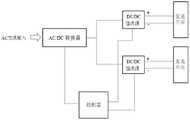
在利用单个开关切换负载时,需要用到控制电路来控制负载的切换。参见图1所示,图1揭示了一种典型的现有技术的控制电路,包括:When using a single switch to switch the load, a control circuit is required to control the switching of the load. Referring to FIG. 1, FIG. 1 discloses a typical prior art control circuit, including:
具有多个发光单元(图1中为两个)的发光器件组,与这些发光单位一一对应的DC/DC恒流源,这些DC/DC恒流源用于分别为这些发光器件供电。控制电路还包括控制器,用于控制DC/DC恒流源的开闭。A light-emitting device group with a plurality of light-emitting units (two in FIG. 1 ), and DC/DC constant current sources corresponding to these light-emitting units one-to-one, and these DC/DC constant current sources are used to supply power to these light-emitting devices respectively. The control circuit further includes a controller for controlling the opening and closing of the DC/DC constant current source.
在上述现有的控制电路中,通常根据检测到的开关动作,通过控制器来控制DC/DC恒流源的输出,实现对分段调节灯具的控制。In the above-mentioned existing control circuit, the output of the DC/DC constant current source is usually controlled by the controller according to the detected switching action, so as to realize the control of the segment-adjusted lamps.
由于DC/DC恒流源的成本相对较高,在现有控制电路中又需要对每一个发光单元对应一个DC/DC恒流源,因此现有的控制电路存在成本高昂的问题。Since the cost of the DC/DC constant current source is relatively high, and each light-emitting unit needs to correspond to a DC/DC constant current source in the existing control circuit, the existing control circuit has the problem of high cost.
发明内容SUMMARY OF THE INVENTION
本发明的目的在于提供一种控制电路和LED照明装置,该控制电路能够降低LED照明装置的生产成本。An object of the present invention is to provide a control circuit and an LED lighting device, the control circuit can reduce the production cost of the LED lighting device.
为了解决上述技术问题,本发明提供了一种控制电路,用于分段调色灯具或分段调光灯具,包括:发光器件组和用于为发光器件组供电的DC/DC恒流源;其中,发光器件组包括多个发光单元及与多个发光单元一一对应的多个开关元件;控制电路还包括与发光器件组连接的控制器,控制器用于控制上述多个开关元件。In order to solve the above-mentioned technical problems, the present invention provides a control circuit for a segmented dimming lamp or a segmented dimming lamp, comprising: a light-emitting device group and a DC/DC constant current source for supplying power to the light-emitting device group; Wherein, the light-emitting device group includes a plurality of light-emitting units and a plurality of switching elements corresponding to the plurality of light-emitting units; the control circuit further includes a controller connected to the light-emitting device group, and the controller is used to control the above-mentioned plurality of switching elements.
本发明还提供了设置有上述控制电路的LED照明装置。The present invention also provides an LED lighting device provided with the above-mentioned control circuit.
相对于现有技术而言,本发明通过设置开关元件,使得一个DC/DC恒流源可以对应多个发光单元设置,大幅度地降低了LED照明装置的成本。Compared with the prior art, the present invention enables one DC/DC constant current source to be set up corresponding to a plurality of light emitting units by setting the switching element, thereby greatly reducing the cost of the LED lighting device.
作为优选,在发光器件组中,至少有两个发光单元所发出的光的色温不同。当两个发光单元的色温不同时,通过开关元件的切换,可以实现LED灯具的分段调色。Preferably, in the light-emitting device group, at least two light-emitting units emit light with different color temperatures. When the color temperatures of the two light-emitting units are different, by switching the switching elements, the segmented color tone of the LED lamps can be realized.
进一步地,作为优选,在发光器件组中,各个发光单元相互串联或并联。并联或串联都能够实现对发光单元的分段控制,而且,相比于并联而言,串联的发光单元可以更好地保持LED电流的均衡。Further, preferably, in the light-emitting device group, each light-emitting unit is connected in series or in parallel with each other. Parallel or series connection can realize segmented control of light-emitting units, and compared with parallel connection, the series-connected light-emitting units can better maintain the balance of LED current.
另外,作为优选,在发光器件组中,至少有一个开关元件为NPN型三极管,一个开关元件为NPN型三极管和PNP型三极管组成的复合管。采用三极管作为开关管可以简化驱动电路,进一步降低成本。In addition, preferably, in the light-emitting device group, at least one switching element is an NPN triode, and one switching element is a composite tube composed of an NPN triode and a PNP triode. Using the triode as the switch can simplify the driving circuit and further reduce the cost.
进一步地,作为优选,在复合管中,NPN型三极管和PNP型三极管之间串联有电阻R1,PNP型三极管的发射极和基极之间并联有电阻R2。设置电阻R1和R2可以为三极管提供稳定的静态工作点。Further, preferably, in the composite tube, a resistor R1 is connected in series between the NPN transistor and the PNP transistor, and a resistor R2 is connected in parallel between the emitter and the base of the PNP transistor. Setting resistors R1 and R2 provides a stable quiescent operating point for the transistor.
除此之外,作为优选,控制电路还包括与外部AC交流输入端连接的AC/DC转换器,AC/DC转换器与DC/DC恒流源相接,用于向DC/DC恒流源供电。通过设置AC/DC转换器,提供了市电的接入,使得控制电路可以在市电环境下得到使用。In addition, preferably, the control circuit further includes an AC/DC converter connected to the external AC input terminal, and the AC/DC converter is connected to the DC/DC constant current source for converting the DC/DC constant current source to the DC/DC constant current source. powered by. By setting the AC/DC converter, the access to the commercial power is provided, so that the control circuit can be used in the commercial power environment.
除此之外,作为优选,DC/DC恒流源为降压式变换电路。借助降压式变化电路可以根据实际的负载需求调整直流电压,保证控制电路的稳定运行。Besides, preferably, the DC/DC constant current source is a step-down conversion circuit. With the help of the step-down change circuit, the DC voltage can be adjusted according to the actual load demand to ensure the stable operation of the control circuit.
除此之外,作为优选,发光单元为LED芯片。LED芯片具有节能环保寿命长等多种优势。Besides, preferably, the light-emitting unit is an LED chip. LED chips have many advantages such as energy saving, environmental protection and long life.
除此之外,作为优选,控制电路被集成在一个半导体衬底上。集成在一个半导体衬底上的控制电路更加小型化,电路的设计也更加简单。Besides, the control circuit is preferably integrated on a semiconductor substrate. The control circuit integrated on a semiconductor substrate is more miniaturized and the circuit design is simpler.
附图说明Description of drawings
图1是本发明现有技术的控制电路的示意图;Fig. 1 is the schematic diagram of the control circuit of the prior art of the present invention;
图2是本发明第一实施方式控制电路的示意图;2 is a schematic diagram of a control circuit according to the first embodiment of the present invention;
图3是本发明第二实施方式控制电路的示意图;3 is a schematic diagram of a control circuit according to a second embodiment of the present invention;
图4是本发明第五实施方式控制电路的示意图;4 is a schematic diagram of a control circuit according to a fifth embodiment of the present invention;
图5是本发明第六实施方式控制电路的示意图。FIG. 5 is a schematic diagram of a control circuit according to a sixth embodiment of the present invention.
具体实施方式Detailed ways
实施方式一Embodiment 1
本发明的第一实施方式提供了一种控制电路,用于分段调色灯具或分段调光灯具,参见图2所示,包括:发光器件组和用于为发光器件组供电的DC/DC恒流源;其中,发光器件组包括多个发光单元及与多个发光单元一一对应的多个开关元件,在图2中,以两个发光单元为例进行说明,实际使用时,发光单元的数量可以不限于两个。The first embodiment of the present invention provides a control circuit for a segmented dimming lamp or a segmented dimming lamp, as shown in FIG. 2, including: a light-emitting device group and a DC/DC/DC/DC/DC/DC/DC/DC/DC/DC/DC/DC/DC/DC/DC/DC controller for powering the light-emitting device group, as shown in FIG. 2 . DC constant current source; wherein, the light-emitting device group includes a plurality of light-emitting units and a plurality of switching elements corresponding to the plurality of light-emitting units one-to-one. In FIG. 2, two light-emitting units are used as an example for illustration. The number of units may not be limited to two.
这两个发光单元中,第一发光单元对应于开关元件S1,第二发光单元对应于开关元件S2。Among the two light-emitting units, the first light-emitting unit corresponds to the switch element S1, and the second light-emitting unit corresponds to the switch element S2.
控制电路还包括与发光器件组连接的控制器,控制器用于控制上述多个开关元件。The control circuit further includes a controller connected to the light-emitting device group, and the controller is used to control the above-mentioned plurality of switching elements.
另外,在发光器件组中,各个发光单元相互并联。并联能够很好地实现对发光单元的分段控制。In addition, in the light emitting device group, the respective light emitting units are connected in parallel with each other. Parallel connection can well realize the segmented control of the light-emitting units.
除此之外,在本实施方式中,控制电路还包括与外部AC交流输入端连接的AC/DC转换器,AC/DC转换器与DC/DC恒流源相接,用于向DC/DC恒流源供电。通过设置AC/DC转换器,提供了市电的接入,使得控制电路可以在市电环境下得到使用。值得一提的是,即使没有AC/DC转换器,仅采用直流供电也能够基本实现本发明的发明目的。In addition, in this embodiment, the control circuit further includes an AC/DC converter connected to the external AC input terminal, and the AC/DC converter is connected to the DC/DC constant current source for converting the DC/DC Constant current source power supply. By setting the AC/DC converter, the access to the commercial power is provided, so that the control circuit can be used in the commercial power environment. It is worth mentioning that even if there is no AC/DC converter, only DC power supply can basically achieve the purpose of the present invention.
在本实施方式中,以图2为例说明一种属于本发明的电路结构的工作原理。In this embodiment, FIG. 2 is taken as an example to describe the working principle of a circuit structure belonging to the present invention.
AC交流输入AC/DC转换器后,经过交/直流转换,成为直流电并为控制器和DC/DC恒流源供电,控制器在第一次检测到电源的导通时,导通开关元件S1和S2,使得DC/DC恒流源同时为第一发光单元和第二发光单元供电并点亮全灯。After AC input AC/DC converter, after AC/DC conversion, it becomes DC power and supplies power to the controller and DC/DC constant current source. When the controller detects the conduction of the power supply for the first time, it turns on the switching element S1 and S2, so that the DC/DC constant current source simultaneously supplies power to the first light-emitting unit and the second light-emitting unit and lights up all lamps.
当控制器在电源关闭并第二次检测到电源的导通时,则导通开关元件S1,断开开关元件S2,使得DC/DC恒流源为第一发光单元供电并点亮第一发光单元。When the controller turns off the power supply and detects the conduction of the power supply for the second time, the switch element S1 is turned on, and the switch element S2 is turned off, so that the DC/DC constant current source supplies power to the first light-emitting unit and lights the first light-emitting unit. unit.
当控制器在电源关闭并第三次检测到电源的导通时,则导通开关元件S2,断开开关元件S1,使得DC/DC恒流源为第二发光单元供电并点亮第二发光单元。When the controller turns off the power supply and detects that the power supply is turned on for the third time, the switch element S2 is turned on, and the switch element S1 is turned off, so that the DC/DC constant current source supplies power to the second light-emitting unit and lights the second light-emitting unit unit.
当控制器在电源关闭并第四次检测到电源的导通时,则导通开关元件S1和开关元件S2,以此循环。When the controller detects that the power is turned on for the fourth time when the power is turned off, the controller turns on the switching element S1 and the switching element S2, and the cycle is repeated.
显然,当第一发光单元与第二发光单元的色温不同时,第一发光单元被点亮意味着照明装置营造出第一发光单元所提供的色温环境。例如当第一发光单元的色温为冷色调而第二发光单元的色温为暖色调时,仅点亮第一发光单元则意味着照明装置提供冷色调的照明,反之则意味着照明装置提供暖色调的照明。此时,照明装置可以提供分段调色功能。Obviously, when the color temperature of the first light-emitting unit and the second light-emitting unit are different, the lighting of the first light-emitting unit means that the lighting device creates a color temperature environment provided by the first light-emitting unit. For example, when the color temperature of the first light-emitting unit is cool and the color temperature of the second light-emitting unit is warm, only lighting the first light-emitting unit means that the lighting device provides cool-tone lighting, and vice versa means that the lighting device provides warm-tone lighting lighting. At this time, the lighting device can provide the function of segmented toning.
而当第一发光单元与第二发光单元的色温相同但亮度不同时,在第一发光单元和第二发光单元之间的切换则可以使照明装置得以提供分段调光功能。When the color temperature of the first light-emitting unit and the second light-emitting unit are the same but the brightness is different, switching between the first light-emitting unit and the second light-emitting unit can enable the lighting device to provide a segmented dimming function.
无论第一发光单元和第二发光单元如何设置,同时点亮第一发光单元和第二发光单元都可以提供最大的照明亮度。Regardless of how the first light emitting unit and the second light emitting unit are arranged, lighting the first light emitting unit and the second light emitting unit at the same time can provide the maximum illumination brightness.
值得一提的是,在本实施方式中,发光器件组为并联。此时若控制器同时导通开关元件S1和S2,第一发光单元和第二发光单元所承受的电压为DC/DC恒流源的供电电压,此时无需额外的设置即可使得第一发光单元和第二发光单元全亮,十分方便。It is worth mentioning that, in this embodiment, the light-emitting device groups are connected in parallel. At this time, if the controller turns on the switching elements S1 and S2 at the same time, the voltage to which the first light-emitting unit and the second light-emitting unit are subjected is the supply voltage of the DC/DC constant current source, and no additional settings are required to make the first light-emitting unit The unit and the second light-emitting unit are fully lit, which is very convenient.
相对于现有技术而言,本发明通过设置开关元件,使得一个DC/DC恒流源可以对应多个发光单元设置。由于开关元件的成本远低于DC/DC恒流源,因此大幅度地降低了LED照明装置的成本。Compared with the prior art, the present invention enables one DC/DC constant current source to be set corresponding to multiple light emitting units by setting the switching element. Since the cost of the switching element is much lower than that of the DC/DC constant current source, the cost of the LED lighting device is greatly reduced.
实施方式二Embodiment 2
本发明的第二实施方式提供了一种控制电路,第二实施方式与第一实施方式有所不同;主要不同之处在于,在本发明的第一实施方式中,在发光器件组中,各个发光单元相互并联;在本发明的第二实施方式中,参见图3所示,在发光器件组中,各个发光单元相互串联。The second embodiment of the present invention provides a control circuit, and the second embodiment is different from the first embodiment; the main difference is that, in the first embodiment of the present invention, in the light-emitting device group, each The light-emitting units are connected in parallel with each other; in the second embodiment of the present invention, as shown in FIG. 3 , in the light-emitting device group, the light-emitting units are connected in series with each other.
并联或串联都能够实现对发光单元的分段控制,而且,对于LED照明灯具而言,由于LED为电流驱动型器件,因此相比于并联而言,串联的发光单元可以更好地保持LED电流的均衡。Both parallel and series can realize segmented control of light-emitting units, and for LED lighting fixtures, since LEDs are current-driven devices, compared with parallel-connected light-emitting units, the LED current can be better maintained. balance.
实施方式三Embodiment 3
本发明的第三实施方式提供了一种控制电路,第三实施方式是第一或第二实施方式的进一步改进;主要改进之处在于,在本发明的第三实施方式中,在发光器件组中,至少有两个发光单元所发出的光的色温不同。当两个发光单元的色温不同时,通过开关元件的切换,可以实现LED灯具的分段调色。The third embodiment of the present invention provides a control circuit, and the third embodiment is a further improvement of the first or second embodiment; the main improvement lies in that, in the third embodiment of the present invention, in the light-emitting device group Among them, at least two light-emitting units emit light with different color temperatures. When the color temperatures of the two light-emitting units are different, by switching the switching elements, the segmented color tone of the LED lamps can be realized.
具体而言,可以令至少一个发光单元的色温低于2500K,对应的其它发光单元的色温高于6500K,从而获得较强的色温对比。Specifically, the color temperature of at least one light-emitting unit may be lower than 2500K, and the color temperature of the corresponding other light-emitting units may be higher than 6500K, so as to obtain a strong color temperature contrast.
实施方式四Embodiment 4
本发明的第四实施方式提供了一种控制电路,第四实施方式是第一至第三实施方式中任意一实施方式的进一步改进;主要改进之处在于,在本发明的第四实施方式中,DC/DC恒流源为降压式变换电路。借助降压式变化电路可以根据实际的负载需求调整直流电压,保证控制电路的稳定运行。The fourth embodiment of the present invention provides a control circuit, and the fourth embodiment is a further improvement of any one of the first to third embodiments; the main improvement is that in the fourth embodiment of the present invention , the DC/DC constant current source is a step-down conversion circuit. With the help of the step-down change circuit, the DC voltage can be adjusted according to the actual load demand to ensure the stable operation of the control circuit.
通过利用PWM脉冲宽度调制,DC/DC恒流源可以根据负载电压自适应调整,实现恒定电流的目的。By using PWM pulse width modulation, the DC/DC constant current source can be adaptively adjusted according to the load voltage to achieve the purpose of constant current.
实施方式五Embodiment 5
本发明的第五实施方式提供了一种控制电路,第五实施方式是第一至第四实施方式中任意一实施方式的进一步改进;主要改进之处在于,在本发明的第五实施方式中,在发光器件组中,至少有一个开关元件为NPN型三极管,一个开关元件为NPN型三极管和PNP型三极管组成的复合管。The fifth embodiment of the present invention provides a control circuit, and the fifth embodiment is a further improvement of any one of the first to fourth embodiments; the main improvement is that in the fifth embodiment of the present invention , In the light-emitting device group, at least one switching element is an NPN triode, and one switching element is a composite tube composed of an NPN triode and a PNP triode.
三极管相较于DC/DC恒流源而言成本几乎可以忽略不计,采用三极管作为开关管还可以简化驱动电路,进一步降低成本。Compared with the DC/DC constant current source, the cost of the triode is almost negligible. Using the triode as the switch can also simplify the driving circuit and further reduce the cost.
举例来说,当发光单元相互串联时,其电路图可以如图4所示,其中,S1为NPN型三极管,S2为NPN型三极管和为PNP型三极管组成的复合管。For example, when the light-emitting units are connected in series, the circuit diagram may be as shown in FIG. 4 , where S1 is an NPN triode, S2 is a composite tube composed of an NPN triode and a PNP triode.
实施方式六Embodiment 6
本发明的第六实施方式提供了一种控制电路,第六实施方式是第五实施方式的进一步改进;主要改进之处在于,在本发明的第六实施方式中,在复合管中,NPN型三极管和PNP型三极管之间串联有电阻R1,PNP型三极管的发射极和基极之间并联有电阻R2。设置电阻R1和R2可以为三极管提供稳定的静态工作点。The sixth embodiment of the present invention provides a control circuit, and the sixth embodiment is a further improvement of the fifth embodiment; the main improvement is that, in the sixth embodiment of the present invention, in the composite pipe, the NPN type A resistor R1 is connected in series between the transistor and the PNP transistor, and a resistor R2 is connected in parallel between the emitter and the base of the PNP transistor. Setting resistors R1 and R2 provides a stable quiescent operating point for the triode.
举例来说,当发光单元相互串联时,其电路图可以如图5所示,其中,S1为NPN型三极管,S2为NPN型三极管和为PNP型三极管组成的复合管,R1和R2为所述的电阻。For example, when the light-emitting units are connected in series, the circuit diagram can be as shown in Figure 5, where S1 is an NPN triode, S2 is a composite tube composed of an NPN triode and a PNP triode, and R1 and R2 are the described resistance.
实施方式七Embodiment 7
本发明的第七实施方式提供了一种控制电路,第七实施方式是第一至第六实施方式中任意一实施方式的进一步改进;主要改进之处在于,在本发明的第七实施方式中,发光单元为LED芯片。The seventh embodiment of the present invention provides a control circuit, and the seventh embodiment is a further improvement of any one of the first to sixth embodiments; the main improvement is that in the seventh embodiment of the present invention , the light-emitting unit is an LED chip.
LED芯片具有节能环保寿命长等多种优势。LED chips have many advantages such as energy saving, environmental protection and long life.
实施方式八Embodiment 8
本发明的第八实施方式提供了一种控制电路,第八实施方式是第一至第七实施方式中任意一实施方式的进一步改进;主要改进之处在于,在本发明的第八实施方式中,控制电路被集成在一个半导体衬底上。The eighth embodiment of the present invention provides a control circuit, and the eighth embodiment is a further improvement of any one of the first to seventh embodiments; the main improvement is that in the eighth embodiment of the present invention , the control circuit is integrated on a semiconductor substrate.
集成在一个半导体衬底上的控制电路更加小型化,电路的设计也更加简单。The control circuit integrated on a semiconductor substrate is more miniaturized and the circuit design is simpler.
实施方式九Embodiment nine
本发明的第九实施方式提供了一种LED照明装置,LED照明装置内设有实施方式一至八中任意一项实施方式所述的控制电路。A ninth embodiment of the present invention provides an LED lighting device, and the LED lighting device is provided with the control circuit described in any one of the first to eighth embodiments.
相对于现有技术而言,本发明通过设置开关元件,使得一个DC/DC恒流源可以对应多个发光单元设置。由于开关元件的成本远低于DC/DC恒流源,因此大幅度地降低了LED照明装置的成本。Compared with the prior art, the present invention enables one DC/DC constant current source to be set corresponding to multiple light emitting units by setting the switching element. Since the cost of the switching element is much lower than that of the DC/DC constant current source, the cost of the LED lighting device is greatly reduced.
本领域的普通技术人员可以理解,在上述的各实施方式中,为了使读者更好地理解本申请而提出了许多技术细节。但是,即使没有这些技术细节和基于上述各实施方式的种种变化和修改,也可以基本实现本申请各权利要求所要求保护的技术方案。因此,在实际应用中,可以在形式上和细节上对上述实施方式作各种改变,而不偏离本发明的精神和范围。It can be understood by those skilled in the art that, in the above-mentioned embodiments, many technical details are provided for the reader to better understand the present application. However, even without these technical details and various changes and modifications based on the above-mentioned embodiments, the technical solutions claimed in the claims of the present application can be basically realized. Accordingly, in practical applications, various changes in form and details of the above-described embodiments may be made without departing from the spirit and scope of the present invention.
Claims (8)
Priority Applications (1)
| Application Number | Priority Date | Filing Date | Title |
|---|---|---|---|
| CN201710040494.XACN108337762B (en) | 2017-01-20 | 2017-01-20 | Control circuit and LED lighting device |
Applications Claiming Priority (1)
| Application Number | Priority Date | Filing Date | Title |
|---|---|---|---|
| CN201710040494.XACN108337762B (en) | 2017-01-20 | 2017-01-20 | Control circuit and LED lighting device |
Publications (2)
| Publication Number | Publication Date |
|---|---|
| CN108337762A CN108337762A (en) | 2018-07-27 |
| CN108337762Btrue CN108337762B (en) | 2022-06-24 |
Family
ID=62922809
Family Applications (1)
| Application Number | Title | Priority Date | Filing Date |
|---|---|---|---|
| CN201710040494.XAActiveCN108337762B (en) | 2017-01-20 | 2017-01-20 | Control circuit and LED lighting device |
Country Status (1)
| Country | Link |
|---|---|
| CN (1) | CN108337762B (en) |
Citations (4)
| Publication number | Priority date | Publication date | Assignee | Title |
|---|---|---|---|---|
| CN102917486A (en)* | 2011-08-02 | 2013-02-06 | 北京同步科技有限公司 | LED lamp adjustable in luminance and color temperature |
| CN103929852A (en)* | 2014-03-31 | 2014-07-16 | 深圳市九洲光电科技有限公司 | LED lamp with light and color capable of being adjusted |
| CN104113972A (en)* | 2014-08-11 | 2014-10-22 | 上海亚明照明有限公司 | LED power supply switching circuit |
| CN104470134A (en)* | 2014-12-09 | 2015-03-25 | 深圳市英集科技有限公司 | Method and device for controlling LED lamp color temperature changing |
Family Cites Families (4)
| Publication number | Priority date | Publication date | Assignee | Title |
|---|---|---|---|---|
| CN103152932A (en)* | 2013-04-21 | 2013-06-12 | 杭州乐图光电科技有限公司 | LED (Light Emitting Diode) drive circuit capable of adjusting light and color temperature |
| CN104684219B (en)* | 2015-03-09 | 2017-05-10 | 北京幻腾科技有限公司 | LED lighting device and drive circuit |
| CN105072753A (en)* | 2015-08-05 | 2015-11-18 | 嘿灯(深圳)智能科技有限公司 | Serial light-emitting diode (LED) dimming circuit |
| CN205726552U (en)* | 2016-04-29 | 2016-11-23 | 南方电网综合能源有限公司 | A kind of control circuit of the light fixture with multibeam optical system |
- 2017
- 2017-01-20CNCN201710040494.XApatent/CN108337762B/enactiveActive
Patent Citations (4)
| Publication number | Priority date | Publication date | Assignee | Title |
|---|---|---|---|---|
| CN102917486A (en)* | 2011-08-02 | 2013-02-06 | 北京同步科技有限公司 | LED lamp adjustable in luminance and color temperature |
| CN103929852A (en)* | 2014-03-31 | 2014-07-16 | 深圳市九洲光电科技有限公司 | LED lamp with light and color capable of being adjusted |
| CN104113972A (en)* | 2014-08-11 | 2014-10-22 | 上海亚明照明有限公司 | LED power supply switching circuit |
| CN104470134A (en)* | 2014-12-09 | 2015-03-25 | 深圳市英集科技有限公司 | Method and device for controlling LED lamp color temperature changing |
Also Published As
| Publication number | Publication date |
|---|---|
| CN108337762A (en) | 2018-07-27 |
Similar Documents
| Publication | Publication Date | Title |
|---|---|---|
| US9844112B2 (en) | Current splitter for LED lighting system | |
| CN101720150B (en) | LED driving circuit, LED lighting device, LED lighting equipment and LED lighting system | |
| WO2013017010A1 (en) | Brightness and color temperature adjustable led lamp | |
| CN105101547A (en) | A multi-channel LED constant current drive circuit, drive method and LED drive power supply | |
| WO2013118208A1 (en) | Light-emitting circuit, light-emitting module, and illumination device | |
| CA2867826C (en) | Driver circuit for solid state light sources | |
| JP2009200257A (en) | Led drive circuit | |
| CN104206019A (en) | Lamp comprising high-efficiency light devices | |
| JP2004296205A (en) | LED dimming lighting device and lighting equipment | |
| CN109302768A (en) | A device for adjusting the brightness and color temperature of an LED light source | |
| CN102892238A (en) | Dimming drive circuit of LED module directly driven by alternating current | |
| TW201019795A (en) | Light-emitting device | |
| CN106605448A (en) | Lighting device | |
| CN111972048B (en) | Voltage transformer of lighting system | |
| CN209659659U (en) | A device for adjusting brightness and color temperature of LED light source | |
| CN108337762B (en) | Control circuit and LED lighting device | |
| KR101326988B1 (en) | Bleed circuit, lighting control circuit and method thereof | |
| TWI410177B (en) | Bypass protection circuit and led driving device using the same | |
| KR20160094020A (en) | Circuit and method to control led lighting apparatus | |
| CN203912269U (en) | Self-excited TRIAC dimming circuit | |
| CN104080236A (en) | LED lamp control system | |
| CN201661916U (en) | Auto-dimming lighting fixtures | |
| JP7724228B2 (en) | DRIVER FOR DRIVING A LOAD, AND CORRESPONDING LED-BASED LIGHTING DEVICE, AND CORRESPONDING METHOD OF OPERATING THE DRIVER - Patent application | |
| JP2017130416A (en) | Driver and lighting device | |
| CN115243419A (en) | Lighting control circuit and lighting device |
Legal Events
| Date | Code | Title | Description |
|---|---|---|---|
| PB01 | Publication | ||
| PB01 | Publication | ||
| SE01 | Entry into force of request for substantive examination | ||
| SE01 | Entry into force of request for substantive examination | ||
| GR01 | Patent grant | ||
| GR01 | Patent grant |