CN108333931B - A two-layer structure gait planning method for quadruped robot for rough terrain - Google Patents
A two-layer structure gait planning method for quadruped robot for rough terrainDownload PDFInfo
- Publication number
- CN108333931B CN108333931BCN201810072219.0ACN201810072219ACN108333931BCN 108333931 BCN108333931 BCN 108333931BCN 201810072219 ACN201810072219 ACN 201810072219ACN 108333931 BCN108333931 BCN 108333931B
- Authority
- CN
- China
- Prior art keywords
- robot
- area
- leg
- planning
- foot
- Prior art date
- Legal status (The legal status is an assumption and is not a legal conclusion. Google has not performed a legal analysis and makes no representation as to the accuracy of the status listed.)
- Active
Links
- 238000000034methodMethods0.000titleclaimsabstractdescription41
- 230000005021gaitEffects0.000titleclaimsabstractdescription38
- 206010034701Peroneal nerve palsyDiseases0.000claimsabstractdescription15
- 210000002414legAnatomy0.000claimsdescription106
- 230000009466transformationEffects0.000claimsdescription21
- 239000011159matrix materialSubstances0.000claimsdescription14
- 210000004394hip jointAnatomy0.000claimsdescription12
- 238000011156evaluationMethods0.000claimsdescription10
- 230000008569processEffects0.000claimsdescription10
- 210000001364upper extremityAnatomy0.000claimsdescription10
- 238000006073displacement reactionMethods0.000claimsdescription9
- 238000005457optimizationMethods0.000claimsdescription9
- 230000007246mechanismEffects0.000claimsdescription7
- 238000010276constructionMethods0.000claimsdescription2
- 238000012876topographyMethods0.000abstract1
- 230000006870functionEffects0.000description25
- 238000010586diagramMethods0.000description8
- 238000004364calculation methodMethods0.000description6
- 210000003141lower extremityAnatomy0.000description6
- 230000008447perceptionEffects0.000description5
- 238000011160researchMethods0.000description3
- 230000008859changeEffects0.000description2
- 230000007613environmental effectEffects0.000description2
- 238000004088simulationMethods0.000description2
- 230000003068static effectEffects0.000description2
- 230000007704transitionEffects0.000description2
- 230000001133accelerationEffects0.000description1
- 238000013459approachMethods0.000description1
- 238000013473artificial intelligenceMethods0.000description1
- 230000009286beneficial effectEffects0.000description1
- 230000008901benefitEffects0.000description1
- 150000001875compoundsChemical class0.000description1
- 230000009193crawlingEffects0.000description1
- 230000000694effectsEffects0.000description1
- 238000005516engineering processMethods0.000description1
- 230000006872improvementEffects0.000description1
- 238000010801machine learningMethods0.000description1
- 239000000463materialSubstances0.000description1
- 230000004048modificationEffects0.000description1
- 238000012986modificationMethods0.000description1
- 238000005381potential energyMethods0.000description1
- 230000035939shockEffects0.000description1
Images


Classifications
- G—PHYSICS
- G05—CONTROLLING; REGULATING
- G05B—CONTROL OR REGULATING SYSTEMS IN GENERAL; FUNCTIONAL ELEMENTS OF SUCH SYSTEMS; MONITORING OR TESTING ARRANGEMENTS FOR SUCH SYSTEMS OR ELEMENTS
- G05B13/00—Adaptive control systems, i.e. systems automatically adjusting themselves to have a performance which is optimum according to some preassigned criterion
- G05B13/02—Adaptive control systems, i.e. systems automatically adjusting themselves to have a performance which is optimum according to some preassigned criterion electric
- G05B13/04—Adaptive control systems, i.e. systems automatically adjusting themselves to have a performance which is optimum according to some preassigned criterion electric involving the use of models or simulators
- G05B13/042—Adaptive control systems, i.e. systems automatically adjusting themselves to have a performance which is optimum according to some preassigned criterion electric involving the use of models or simulators in which a parameter or coefficient is automatically adjusted to optimise the performance
Landscapes
- Engineering & Computer Science (AREA)
- Health & Medical Sciences (AREA)
- Artificial Intelligence (AREA)
- Computer Vision & Pattern Recognition (AREA)
- Evolutionary Computation (AREA)
- Medical Informatics (AREA)
- Software Systems (AREA)
- Physics & Mathematics (AREA)
- General Physics & Mathematics (AREA)
- Automation & Control Theory (AREA)
- Manipulator (AREA)
Abstract
Description
Translated fromChinese技术领域technical field
本发明属于机器人技术领域,具体涉及一种面向崎岖地形的四足运动规划方法。The invention belongs to the technical field of robots, and in particular relates to a quadruped motion planning method oriented to rough terrain.
背景技术Background technique
根据地面移动机器人组成结构和运动形式的不同主要分为履带式、轮式、足式以及复合式。与其他两种独立的运动形式相比,足式运动的足端轨迹是一系列离散点,可利用孤立的触地点进行支撑,因此具有很强的越障能力和地形适应性,适宜于崎岖地形的稳定行走研究。四足机器人是集机械、电子、材料、控制和人工智能等多学科于一体的研究平台,同时一直是机器人领域的研究热点之一。According to the different structure and movement form of ground mobile robot, it is mainly divided into crawler type, wheel type, foot type and compound type. Compared with the other two independent forms of movement, the foot-end trajectory of the foot movement is a series of discrete points, which can be supported by isolated touchdown points, so it has strong obstacle-surmounting ability and terrain adaptability, and is suitable for rough terrain. stable walking study. The quadruped robot is a multi-disciplinary research platform integrating mechanics, electronics, materials, control and artificial intelligence, and has always been one of the research hotspots in the field of robotics.
足式机器人结合装载于机身的双目视觉、激光雷达等环境感知传感器检测并处理的地形信息,根据自身稳定性及机械结构的运动性约束,获取上层全局路径规划输出的最优路径,规划出一系列从起始点到临时目标终点的落足点及质心轨迹,实现机器人在具有禁止区域的结构化地形(如台阶、沟壑等)中基于静步态的四足稳定行走。关于这方面的运动规划研究,许多学者结合图搜索、启发式搜索、机器学习和优化等方法进行落足点及质心轨迹的搜索,均需要进行大规模的数据计算及匹配。The footed robot combines the terrain information detected and processed by environmental perception sensors such as binocular vision and lidar mounted on the fuselage, and obtains the optimal path output by the upper-level global path planning according to its own stability and the kinematic constraints of the mechanical structure. A series of footfall points and mass center trajectories from the starting point to the temporary target end point are obtained to realize the stable walking of the robot based on static gait in structured terrain with forbidden areas (such as steps, ravines, etc.). Regarding motion planning research in this area, many scholars combine graph search, heuristic search, machine learning and optimization to search for foothold and centroid trajectories, all of which require large-scale data calculation and matching.
现有论文“Improving traversability of quadruped walking robots usingbodymovement in 3D rough terrains”针对四足爬行机器人的机械结构设计出一个梯形落足点搜索区域,有效地避免低可能性落足点的低效计算,但在给定规划路径的搜索方向上不能实现最大步长的目标落足点搜索,且未能结合地形特征及运动约束获得最优的目标落足点搜索。The existing paper "Improving traversability of quadruped walking robots using bodymovement in 3D rough terrains" designs a trapezoidal footfall search area for the mechanical structure of quadruped crawling robots, which effectively avoids the inefficient calculation of low-probability footfalls. In the search direction of a given planned path, the target landing point search with the maximum step size cannot be achieved, and the optimal target landing point search cannot be obtained by combining terrain features and motion constraints.
现有论文“Acombined potential function and graphsearch approach forfree gait generation of quadruped robots”采用自由步态的规划序列,结合一个势能函数和图搜索的方法在二维平面地图中对落足点与质心的轨迹进行规划,完成平坦路面中机器人绕开障碍物的运动,但每次搜索任务需要对整个地图进行遍历,使得计算量大且搜索效率低,能得到更优化的目标落足点搜索。The existing paper "Acombined potential function and graphsearch approach for free gait generation of quadruped robots" uses the planning sequence of free gait, combined with a potential energy function and graph search method to plan the trajectory of the foothold and centroid in a two-dimensional plane map , to complete the movement of the robot around obstacles on a flat road, but each search task needs to traverse the entire map, which makes the calculation amount large and the search efficiency low, and a more optimized target landing point search can be obtained.
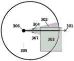
现有论文“Search-based footplacement for quadrupedal traversal ofchallenging terrain”提出将以当前落足点为中心的1×20cm栅格区域作为目标落足点搜索区域,能够有效地提高计算效率并且完成了在崎岖地形中机器人完整的越障运动,但只能实现在直线运动单方向上的搜索规划,一定程度地降低了机器人的运动速度与效率。例如,当机器人的摆动腿处于图3中的当前落足点306时,在摆动腿工作空间305内,当沿着搜索方向301按照直线型搜索区域307进行搜索时,直线型搜索区域303被障碍物或凹坑等构成的禁止区域303覆盖的部分较大时,会使得目标落足点的步长和支撑三角形面积较小,降低机器人运动速度和稳定性,而本发明提出的扇形搜索区域302在该种情形下仍可得到较大步长和支撑三角形的目标落足点,在不降低机器人运动速度和稳定性的条件下提高机器人的地形适应性。The existing paper "Search-based footplacement for quadrupedal traversal ofchallenging terrain" proposes to use the 1×20cm grid area centered on the current foothold as the target footplace search area, which can effectively improve the computational efficiency and complete the search on rough terrain. However, it can only realize the search planning in one direction of linear motion, which reduces the movement speed and efficiency of the robot to a certain extent. For example, when the swinging leg of the robot is at the
综上,虽然现有文献尝试解决四足机器人在崎岖地形上稳定行走的问题,但具有许多局限性。In summary, although existing literature attempts to solve the problem of stable walking of quadruped robots on rough terrain, they have many limitations.
发明内容SUMMARY OF THE INVENTION
有鉴于此,本发明提供了一种面向崎岖地形的四足机器人双层结构步态规划方法,在不降低机器人运动速度和稳定性的条件下,提高解算效率,以及机器人的地形适应性。In view of this, the present invention provides a double-layer structure gait planning method for a quadruped robot facing rough terrain, which can improve the solution efficiency and the terrain adaptability of the robot without reducing the movement speed and stability of the robot.
为了解决上述技术问题,本发明是这样实现的。In order to solve the above-mentioned technical problems, the present invention is realized in this way.
一种面向崎岖地形的四足机器人双层结构步态规划方法,用于依据给定的规划路径完成步态规划,包括如下步骤:A double-layer structure gait planning method for a quadruped robot oriented to rough terrain, which is used to complete gait planning according to a given planning path, including the following steps:
步骤1:建立包含可通行区域和禁止区域的栅格地图,选择步态序列;Step 1: Build a grid map including passable areas and prohibited areas, and select the gait sequence;
步骤2:进行上层运动规划:依据步态序列为每个摆动相下的摆动腿进行落足点的规划,为每个支撑相进行机器人躯干的质心轨迹规划,形成每一步的最优目标运动状态,直至到达所述给定的规划路径的终点;Step 2: Perform upper-level motion planning: According to the gait sequence, plan the landing point for each swinging leg under each swing phase, and perform the trajectory planning of the center of mass of the robot torso for each support phase to form the optimal target motion state for each step. , until reaching the end point of the given planned path;
所述落足点的规划为:在栅格地图中建立四足机器人中当前摆动腿的扇形搜索区域,在扇形搜索区域的可通行区域中找到最优目标落足点的坐标;所述扇形搜索区域的构建为:在当前摆动腿的工作空间中,以当前落足点为顶点,当前落足点到足端工作空间边界的距离为半径,以给定的规划路径中的搜索方向为角平分线,建立一个圆心角为30度且可能与禁止区域产生重叠的扇形搜索区域;The planning of the landing point is as follows: establishing a fan-shaped search area of the current swinging leg of the quadruped robot in the grid map, and finding the coordinates of the optimal target landing point in the passable area of the fan-shaped search area; the fan-shaped search The construction of the area is: in the workspace of the current swing leg, take the current footfall point as the vertex, the distance from the current footfall point to the boundary of the foot end workspace as the radius, and take the search direction in the given planned path as the angle bisector Line, establish a sector search area with a central angle of 30 degrees that may overlap with the forbidden area;
步骤3:进行底层运动控制:根据步骤1选择的步态序列和步骤2形成的最优目标运动状态,控制机器人的各个关节,执行支撑相和摆动相的运动过程。Step 3: Perform the underlying motion control: According to the gait sequence selected in
优选地,所述步骤2中,在进行当前摆动腿的落足点规划时,如果没有满足规划要求的目标落足点,则当前落足点即为目标落足点,即当前的摆动腿不再进行运动,直接转向下一个摆动相的最优目标落足点规划。Preferably, in the
优选地,所述步骤2中,搜索最优目标落足点的坐标的方式为:Preferably, in the
将扇形搜索区域中可通行区域和禁止区域作为待搜索区域;每个栅格单元对应一个可通行代价,禁止区域内栅格单元的可通行代价大于可通行区域内栅格单元的可通行代价,且二者之差大于设定阈值;Take the passable area and forbidden area in the sector search area as the area to be searched; each grid cell corresponds to a passable cost, and the passable cost of the grid cell in the forbidden area is greater than the passable cost of the grid cell in the passable area, And the difference between the two is greater than the set threshold;
针对待搜索区域中的每个栅格i,计算栅格i的优化评价函数值

所述多因素规划函数为:
其中,将机器人机身上左前髋关节和右前髋关节之间的间距,以及左后髋关节和右后髋关节之间的间距,称为初始间距;获得栅格i和与当前摆动腿在同一排的左/右腿的距离,称为当前间距;获得当前间距与相应初始间距差的绝对值,记为

优选地,所述可通行代价定义方法为:根据栅格单元对应的地形崎岖度,将禁止区域内栅格单元可通行代价定义为+∞,可通行区域内栅格单元的可通行代价为0。Preferably, the method for defining the passable cost is: according to the terrain roughness corresponding to the grid cell, the passable cost of the grid cell in the forbidden area is defined as +∞, and the passable cost of the grid cell in the passable area is 0 .
优选地,该方法进一步设定运动约束,所述步骤2从扇形搜索区域中去掉不满足运动约束的不可达落足点;对于具有并联足式机构的四足机器人,所述运动约束包括:Preferably, the method further sets motion constraints, and the
A、目标落足点不能引起前后腿的碰撞;A. The target landing point cannot cause the collision between the front and rear legs;
B、目标落足点满足同一侧的前后两腿之间的距离小于预设长度λ;B. The distance between the front and rear legs of the target footing point on the same side is less than the preset length λ;
C、目标落足点需要使得在下一摆动相中的支撑三角形面积足够大,即同一侧前后两腿之间沿X轴的距离及同一排左右两腿之间沿Y轴的距离分别大于预设值μx和μy;Y轴为当前机器人的正前方,X轴为与Y轴垂直的侧向;C. The target landing point needs to make the area of the supporting triangle in the next swing phase large enough, that is, the distance between the front and rear legs on the same side along the X axis and the distance between the left and right legs in the same row along the Y axis are respectively greater than the preset Values μx and μy ; the Y axis is the front of the current robot, and the X axis is the lateral direction perpendicular to the Y axis;
优选地,所述优化评价函数为多目标多约束优化评价函数:Preferably, the optimization evaluation function is a multi-objective multi-constraint optimization evaluation function:


其中(xi,yi)为栅格i的坐标,

运动阈度


优选地,通过在所述多因素规划函数中加入三个影响因素的权值w1,w2,w3,来调整规划的偏好特性,使机器人适应不同的地形;加入权值的多因素规划函数为:Preferably, by adding weights w1 , w2 , w3 of three influencing factors to the multi-factor planning function, the preference characteristics of the planning are adjusted, so that the robot can adapt to different terrains; multi-factor planning by adding weights The function is:

其中,利用w1来调整机器人运动性能的指标,w1越大,运动速度越快,支撑腿构成的支撑三角形越大;Among them, use w1 to adjust the index of the robot's motion performance, the larger w1 , the faster the movement speed, and the larger the support triangle formed by the support legs;
利用w2来调整具有并联足式机构的四足机器人在崎岖地形上的运动稳定性, w2越大,稳定性越高;Use w2 to adjust the motion stability of the quadruped robot with parallel foot mechanism on rough terrain, the larger w2 , the higher the stability;
利用w3来调整与给定的规划路径之间的偏差,w3越小,偏差越小。Usew3 to adjust the deviation from the given planned path, the smaller thew3 , the smaller the deviation.
优选地,所述步骤3在进行支撑相的运动控制时,包括支撑相躯干调整参数的设定,涵盖机器人质心的横滚角αd、俯仰角βd、方位角γd和质心相对地面高度Δz四个自由度的调整;支撑相的运动控制还包括利用引入了摆线插值系数的变换矩阵,进行支撑相中躯干的位姿变换;Preferably, when the motion control of the support phase is performed in the
所述引入了摆线插值系数的变换矩阵包括∑N到∑D的变换矩阵


其中,摆线插值系数
T()表示3×3的正交齐次旋转矩阵;位移增量Δ=[Δx Δy Δz]中,Δx、Δy为步骤2为每个支撑相进行质心轨迹规划的结果;α、β和γ分别为装载于机器人躯干上的姿态传感器所测得的横滚角、俯仰角、方位角。T() represents a 3×3 orthogonal homogeneous rotation matrix; in the displacement increment Δ=[Δx Δy Δz], Δx and Δy are the results of centroid trajectory planning for each support phase in
优选地,所述步态序列为:右后摆动腿、支撑相、右前摆动腿、支撑相、左后摆动腿、支撑相、左前摆动腿。Preferably, the gait sequence is: right rear swing leg, support phase, right front swing leg, support phase, left rear swing leg, support phase, left front swing leg.
优选地,所述步骤2为每个支撑相进行质心轨迹规划的方式为:在对前摆动腿触地后的支撑相中进行质心轨迹规划时,质心移动;在对后摆动腿触地后的支撑相进行质心轨迹规划时,质心保持原位置不变;Preferably, the method of performing the trajectory planning of the center of mass for each support phase in
在需要质心移动时,当上一个摆动腿触地,另外三个支撑腿构成第一个支撑三角形;当下一个摆动腿触地,另外三个支撑腿构成第二个支撑三角形,则形成双支撑三角形;将两个支撑三角形重叠,将质心投影于该双三角形重叠区,沿质心作平行于X轴的直线,该直线与双三角形重叠区相交后截断的线段长度即为质心沿X轴正向的位移Δx,并设置一个质心沿Y轴向双三角形重叠区内部的侧向位移Δy,从而得到支撑相中x-y平面的质心移动轨迹;所述Y轴为当前机器人的正前方,X轴为与Y轴垂直的侧向。When the center of mass needs to move, when the previous swing leg touches the ground, the other three support legs form the first support triangle; when the next swing leg touches the ground, the other three support legs form the second support triangle, forming a double support triangle ; Overlap the two supporting triangles, project the centroid on the overlapping area of the double triangle, and draw a straight line parallel to the X-axis along the centroid. The length of the truncated line segment after the line intersects the overlapping area of the double triangle is the centroid along the positive X axis. Displace Δx, and set a lateral displacement Δy of the center of mass along the Y-axis inside the double triangle overlapping area, so as to obtain the movement trajectory of the center of mass in the x-y plane in the support phase; the Y-axis is the front of the current robot, and the X-axis is the same as the Y-axis. The axis is vertical laterally.
有益效果:Beneficial effects:
(1)本发明采用扇形搜索区域作为最优目标落足点的搜索区域,而非全局遍历搜索,提高了计算效率,实现了全方位而非单一搜索方向的落足点规划,克服了原始梯形搜索区域在给定规划路径的搜索方向上不能实现最大步长目标落足点搜索的缺点;在构建好的栅格地图中,根据栅格单元对应的地形复杂度和机器人触地足端的几何形状,对每个栅格进行可通行性评价,将可能引起机器人倾翻的区域定义为禁止区域,可以结合规划指标和栅格可通行代价进行最优目标落足点的搜索,从而实现机器人跨越障碍(台阶边缘、沟壑等)的四足运动。(1) The present invention adopts a fan-shaped search area as the search area of the optimal target landing point, rather than a global traversal search, which improves the calculation efficiency, realizes the landing point planning in all directions instead of a single search direction, and overcomes the original trapezoidal shape. The shortcoming that the search area cannot achieve the maximum step size in the search direction of the given planned path for the target landing point search; in the constructed grid map, according to the terrain complexity corresponding to the grid cell and the geometry of the robot's ground foot end , evaluate the accessibility of each grid, define the area that may cause the robot to tip over as a forbidden area, and combine the planning index and grid accessibility cost to search for the optimal target landing point, so that the robot can overcome obstacles Quadrupedal movement (edges of steps, ravines, etc.).
(2)本发明在最优目标落足点搜索中加入运动约束的限制,去掉了不满足运动约束的落足点,防止机器人前后腿碰撞产生倾翻和腿间距离过近导致足端支撑面过小而产生倾翻,并为后续搜索减少计算量。(2) The present invention adds the restriction of motion constraints in the search for the optimal target landing point, removes the landing points that do not meet the motion constraints, and prevents the robot from overturning due to collision between the front and rear legs of the robot and the distance between the legs being too close, which leads to the support surface of the foot end Too small will cause tipping and reduce computation for subsequent searches.
(3)本发明构建多因素规划函数进行最优目标落足点的搜索,可以使目标落足点满足多方面不同的规划需求。(3) The present invention constructs a multi-factor planning function to search for the optimal target landing point, so that the target landing point can meet various planning requirements in different aspects.
(4)本发明构建多约束优化评价函数进行最优目标落足点的搜索,旨在使目标落足点能极大提高机器人四足运动中速度和稳定性的运动性能。(4) The present invention constructs a multi-constraint optimization evaluation function to search for the optimal target landing point, so that the target landing point can greatly improve the motion performance of speed and stability in the quadruped motion of the robot.
(5)本发明在规划落足点时,并非仅在扇形搜索区域的可通行区域进行搜索,而是将可通行区域和禁止区域都作为待搜索区域,采用可通行代价的方式,将禁止区域排除在可能的落足点之外,这样做的好处是:搜索过程将扇形搜索区域与禁止区域重叠部分的所有落足点进行遍历并去掉,不会因为遗漏而造成机器人跨入禁止区域。(5) When planning the foothold, the present invention does not only search in the passable area of the fan-shaped search area, but takes both the passable area and the prohibited area as the area to be searched, and adopts the method of passable cost to search the prohibited area. The advantage of excluding the possible landing points is that the search process traverses and removes all landing points in the overlapping part of the fan-shaped search area and the forbidden area, so that the robot will not step into the forbidden area due to omission.
(6)本发明在多因素规划函数中加入三个影响因素的权值w1,w2,w3,三个权值分别表征影响因素的比重,通过调整权值可以调整规划的偏好特性,使机器人适应不同的地形,进而提高机器人运动的稳定性。(6) In the present invention, weights w1 , w2 , and w3 of three influencing factors are added to the multi-factor planning function, and the three weights represent the proportions of the influencing factors respectively. By adjusting the weights, the preference characteristics of the planning can be adjusted, Make the robot adapt to different terrains, thereby improving the stability of the robot movement.
(7)本发明在支撑相的躯干位姿变换过程中引入了摆线插值系数的变换矩阵,使得起始时刻和结束时刻的运动加速度和速度均为0,且摆线轨迹在起始阶段和结束阶段的位移量相对于中间阶段的位移量较少,减少躯干位姿变换过程中的冲击和晃动。(7) The present invention introduces a transformation matrix of cycloid interpolation coefficients in the process of the torso pose transformation of the support phase, so that the motion acceleration and speed at the start time and the end time are both 0, and the cycloid trajectory is at the initial stage and The displacement in the end stage is smaller than that in the middle stage, which reduces the shock and shaking during the transformation of the torso pose.
附图说明Description of drawings
图1是本发明所述的四足运动双层式规划方法结构图;Fig. 1 is the structure diagram of quadruped bi-level planning method of the present invention;
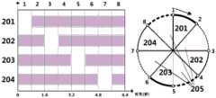
图2是间歇步态的步态序列;Figure 2 is a gait sequence of intermittent gait;
图3是摆动腿扇形搜索区域示意图;Fig. 3 is a schematic diagram of a swing leg fan-shaped search area;
图4是x-y平面上质心轨迹规划准则示意图;Fig. 4 is a schematic diagram of a centroid trajectory planning criterion on the x-y plane;
图5是局部运动规划所采用的崎岖地形四足机器人目标位姿搜索流程图;Figure 5 is a flowchart of the target pose search for a quadruped robot on rough terrain used in local motion planning;
图6是摆动腿轨迹及落足区域示意图;6 is a schematic diagram of a swing leg trajectory and a foot landing area;
图7是本发明实施例1与实施例2中使用的Stewart型电动并联轮足机器人的物理样机及其组成和尺寸;Fig. 7 is the physical prototype of the Stewart type electric parallel wheel-foot robot used in
图8(a)是本发明实施例1中局部路径规划层的输出;Figure 8(a) is the output of the local path planning layer in
图8(b)是本发明实施例2中局部路径规划层的输出;Figure 8(b) is the output of the local path planning layer in
图9是本发明实施例1中Stewart型电动并联轮足机器人在具有沟壑的楼梯上直线路径的足式稳定行走示意图;9 is a schematic diagram of the stable walking of the Stewart type electric parallel wheel-footed robot in a straight line path on a staircase with ravines in
图10是本发明实施例2中Stewart型电动并联轮足机器人在具有横滚角变化的沟壑地形上全方位的足式稳定行走示意图。FIG. 10 is a schematic diagram of the Stewart-type electric parallel wheel-footed robot walking stably in all directions on a ravine terrain with a change in roll angle according to
具体实施方式Detailed ways
下面结合附图并举实施例,对本发明进行详细描述。The present invention will be described in detail below with reference to the accompanying drawings and embodiments.
本发明提出一种适用于通用四足机器人在崎岖地形行走的运动规划方法,主要涉及了一种双层式运动规划方法,分为上层运动规划和底层控制两部分,以实现崎岖地形四足稳定行走的运动任务,来提高四足机器人的环境适应性,同时提高解算效率。该方案的核心思想是:在上层运动规划的摆动腿落足点规划中,采用扇形搜索区域作为落足点的规划区,而非采用全局搜索方式,从而提高解算效率。进一步的,在摆动腿落足点规划中,结合运动约束、权值规划函数、多目标多约束优化评价函数搜索一系列目标落足点及质心轨迹;底层控制部分根据获得的目标落足点和质心轨迹来控制机器人的各个关节执行支撑相和摆动相的运动过程,完成摆动腿的轨迹规划、质心的位姿调整与平滑过渡。The invention proposes a motion planning method suitable for a general-purpose quadruped robot to walk on rough terrain, and mainly relates to a double-layer motion planning method, which is divided into two parts: upper-layer motion planning and bottom-layer control, so as to realize quadruped stability on rough terrain The task of walking is used to improve the environmental adaptability of the quadruped robot and improve the calculation efficiency. The core idea of this scheme is: in the upper-level motion planning of the swing leg landing point planning, the fan-shaped search area is used as the landing point planning area, rather than the global search method, so as to improve the solution efficiency. Further, in the footfall planning of the swinging leg, a series of target footfalls and mass center trajectories are searched by combining motion constraints, weight programming functions, and multi-objective multi-constraint optimization evaluation functions; the underlying control part is based on the obtained target footfalls and The trajectory of the center of mass is used to control each joint of the robot to perform the motion process of the support phase and the swing phase, and complete the trajectory planning of the swing leg, the pose adjustment and smooth transition of the center of mass.
本发明实施例所采用的Stewart型电动并联轮足机器人将底部驱动轮锁死,则可进行纯足式的运动。其主要由控制系统701、IMU702、能源系统703、环境感知系统704、组合导航系统705和机械结构(上平台706、轮足驱动机构707 和足端轮组708)构成。The Stewart-type electric parallel wheel-footed robot used in the embodiment of the present invention locks the bottom driving wheel, so that pure-footed motion can be performed. It is mainly composed of
实施例1是利用本发明方法实现Stewart型电动并联轮足机器人在具有沟壑、不连续的凸台901上进行足式稳定行走,除掉起点和终点的平台,凸台的长度从22cm到35cm不等,高度从29cm到90cm不等。图8-(a)是实施例1中局部路径规划层的输出,由环境感知系统704采集并分析得到的栅格地图,根据地形崎岖度等特征化分为禁止区域801和可通行区域802,从四足起始位置810和质心起始位置808到目标质心位置803之间的左后腿目标落足点804、右后腿目标落足点805、左前腿目标落足点806和右前腿目标落足点809组成的直线型目标运动规划,图9是实施例1中Stewart型电动并联轮足机器人进行稳定行走的 3D仿真示意图。
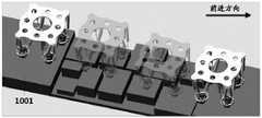
实施例2是利用本发明方法实现Stewart型电动并联轮足机器人在具有横滚角变化的沟壑地形1001进行足式稳定行走,除掉起点和终点的平台,凸台的长度从34cm到100cm不等,宽度从29到86不等,高度从17cm到38cm不等。图8-(b)是实施例2中局部路径规划层的输出,由环境感知系统704采集并分析得到的栅格地图根据地形崎岖度等特征化分为禁止区域801和可通行区域802,从四足起始位置810和质心起始位置808到目标质心位置803之间的左后腿目标落足点804、右后腿目标落足点805、左前腿目标落足点806和右前腿目标落足点809组成的直线型目标运动规划,图10是实施例2中Stewart型电动并联轮足机器人进行稳定行走的3D仿真示意图。
实施例2与实施例1所采用的步态规划方法和过程完全一致,区别仅仅在于步态规划的相关参数和崎岖地形不同,以下具体实施方式仅对实施例1和实施例2的规划过程进行详细介绍。The gait planning method and process used in Example 2 and Example 1 are exactly the same, and the only difference is that the relevant parameters of gait planning and rough terrain are different. Details.
步骤一、建立包含可通行区域和禁止区域的栅格地图:如图7所示,将由装载于机器人的环境感知系统704(如双目视觉、激光雷达等)检测并处理的地图信息划分为以1cm2为单元的栅格地图,每个栅格单元对应的地形复杂度(即地形几何特征参数,包括高度、崎岖程度和坡度),根据机器人触地足端的几何形状(触地区域601、沿X方向的预留空间604和沿Y方向的预留空间606),将可能引起机器人倾翻的区域定义为禁止区域(如台阶边缘、沟壑等)。
每个栅格单元对应的一个可通行代价,禁止区域801内栅格单元的可通行代价大于可通行区域802内栅格单元的可通行代价,二者之差大于设定阈值,这样才能在搜索落足点时将禁止区域排除在外。一种优选的可通行代价设定方式为:根据栅格单元对应的地形崎岖度,将禁止区域801内栅格单元可通行代价定义为+∞,可通行区域802内栅格单元的可通行代价为0。Each grid cell corresponds to a passable cost. The passable cost of the grid cells in the forbidden
步骤二、选择步态序列:根据机器人的机构特征及运动特性选择恰当的步态序列,本实施例采用大负载机器人,由于其重腿易产生惯性效应的缺点则选择间歇步态,将摆动相(一个步态周期内,摆动腿抬起、在空中摆动并落地的过程)的四足运动与支撑相(一个步态周期内,四足均触地并起支撑作用的同时躯干运动的过程)的躯干移动分开,以减少动力学扰动,提高行走过程中的稳定性。采用标准静步态序列如图2所示,依次为右后摆动腿201——支撑相 205——右前摆动腿202——支撑相205——左后摆动腿203——支撑相205——左前摆动腿204——支撑相205。其中,201~204为摆动相。一组摆动相+支撑相完成一步的步态运动。Step 2: Select the gait sequence: select the appropriate gait sequence according to the mechanical characteristics and motion characteristics of the robot. In this embodiment, a large-load robot is used. Due to the disadvantage that its heavy legs are prone to inertial effects, the intermittent gait is selected, and the swing phase is changed. (In a gait cycle, the swinging leg lifts, swings in the air and falls to the ground) quadrupedal movement and support phase (in a gait cycle, all four feet touch the ground and play a supporting role while the trunk moves) The torso moves apart to reduce dynamic disturbances and improve stability during walking. The standard static gait sequence is used as shown in Figure 2, and the sequence is right rear swing leg 201 - support phase 205 - right front swing leg 202 - support phase 205 - left rear swing leg 203 - support phase 205 - left front Swing leg 204 -
步骤三、进行上层运动规划:依据步态序列为每个摆动相下的摆动腿进行落足点的规划,为每个支撑相进行质心轨迹规划,形成每一步的最优目标运动状态,直至到达所述给定的规划路径的终点。
本步骤包括如下子步骤:This step includes the following sub-steps:
子步骤31:依据步态序列进行第一个摆动腿落足点的规划。Sub-step 31 : planning the landing point of the first swing leg according to the gait sequence.
本步骤中,首先建立摆动腿扇形搜索区域:如图3所示,在当前摆动腿的工作空间305中,以当前落足点306为顶点,当前落足点到足端工作空间边界的距离为半径,以给定的规划路径中的搜索方向301为角平分线,建立一个圆心角304为30度且可能与禁止区域303产生重叠的扇形搜索区域302。In this step, first establish a sectoral search area for the swinging leg: as shown in FIG. 3 , in the working
接着,从所建立的扇形搜索区域中去掉不满足运动约束的不可达落足点,获得剩余区域R。这里,没有去掉禁止区域,禁止区域是在利用多因素规划函数确定目标落足点时,由于禁止区域对应的可通行代价值较大,而被去掉的。Next, the unreachable footholds that do not satisfy the motion constraints are removed from the established sector search area, and the remaining area R is obtained. Here, the forbidden area is not removed. The forbidden area is removed when the target landing point is determined by using the multi-factor planning function because the passable cost value corresponding to the forbidden area is relatively large.
其中,针对并联足式机构的四足机器人机械结构的运动特点,扇形搜索区域中的目标落足点需要满足下述三个运动约束:Among them, according to the motion characteristics of the quadruped robot mechanical structure of the parallel-foot mechanism, the target landing point in the fan-shaped search area needs to meet the following three motion constraints:
A、目标落足点不能引起前后腿的碰撞;A. The target landing point cannot cause the collision between the front and rear legs;
B、目标落足点满足同一侧的前后两腿之间的距离小于预设长度λ;B. The distance between the front and rear legs of the target footing point on the same side is less than the preset length λ;
C、目标落足点需要使得在下一摆动相中的支撑三角形面积足够大,即同一侧前后两腿之间沿X轴的距离及同一排左右两腿之间沿Y轴的距离分别大于预设值μx和μy;Y轴为当前机器人的正前方,X轴为与Y轴垂直的侧向。C. The target landing point needs to make the area of the supporting triangle in the next swing phase large enough, that is, the distance between the front and rear legs on the same side along the X axis and the distance between the left and right legs in the same row along the Y axis are respectively greater than the preset Values μx andμy ; theY axis is the front of the current robot, and the X axis is the lateral direction perpendicular to the Y axis.
最后,在剩余的区域R中搜索最优目标落足的坐标。如果没有满足规划要求的目标落足点,则当前落足点即为目标落足点,即当前的摆动腿不再进行运动,直接转向下一步的步态规划。Finally, the coordinates of the optimal target landing are searched in the remaining region R. If there is no target footfall point that meets the planning requirements, the current footfall point is the target footfall point, that is, the current swing leg no longer moves, and directly turns to the next step of gait planning.
本步骤中如何从区域R中获得最优的栅格,即最优目标落足点是关键技术。本发明采用多因素规划函数实现最优的栅格的选拔。具体来说:In this step, how to obtain the optimal grid from the region R, that is, the optimal target landing point is the key technology. The invention adopts the multi-factor planning function to realize the selection of the optimal grid. Specifically:
针对待搜索区域中的每个栅格i,计算栅格i的优化评价函数值

多因素规划函数有三个因素组成,表达为:The multifactor programming function consists of three factors, expressed as:

其中,


上述公式(1)中的三个因素可以通过加入权值来调整规划的偏好特性使机器人适应不同的地形,加入权值后的多因素规划函数变形为公式(2):The three factors in the above formula (1) can be adjusted by adding weights to adjust the preference characteristics of the planning to make the robot adapt to different terrains. The multi-factor planning function after adding weights is transformed into formula (2):

w1,w2,w3为三个影响因素的权值。利用w1来调整机器人运动性能的指标,w1越大,运动速度越快,支撑腿构成的支撑三角形越大;利用w2来调整具有并联足式机构的四足机器人在崎岖地形上的运动稳定性,w2越大,稳定性越高;利用 w3来调整与给定的规划路径之间的偏差,w3越小,偏差越小。例如将w3减小为 0,机器人将只进行直线方向的目标落足点搜索;而当地形崎岖度较高时,可将 w2设置较高而w1设置较低来使并联式机器人在保证高稳定性的前提下获得较优的目标落足点搜索规划。w1 , w2 , w3 are the weights of the three influencing factors. Use w1 to adjust the index of the robot's motion performance, the larger w1 , the faster the movement speed, and the larger the support triangle formed by the support legs; use w2 to adjust the motion of the quadruped robot with parallel-footed mechanism on rough terrain Stability, the larger the w2 , the higher the stability; the use of w3 to adjust the deviation from the given planned path, the smaller the w3 , the smaller the deviation. For example, if w3 is reduced to 0, the robot will only search for the target landing point in the straight line direction; and when the terrain is rough, w2 can be set higher and w1 can be set lower to make the parallel robot in the Under the premise of ensuring high stability, a better target landing point search plan can be obtained.
在本优选实施例中,优化评价函数采用多目标多约束优化评价函数,如下式(3)所示:In this preferred embodiment, the optimization evaluation function adopts a multi-objective multi-constraint optimization evaluation function, as shown in the following formula (3):


其中,(xi,yi)为栅格i的坐标,

运动阈度


子步骤32、依据步态序列,进行支撑相中质心的轨迹规划。其中,在对前摆动腿触地后的支撑相中进行质心轨迹规划时,质心移动;在对后摆动腿触地后的支撑相进行质心轨迹规划时,质心保持原位置不变。Sub-step 32: According to the gait sequence, plan the trajectory of the center of mass of the support phase. Among them, when planning the trajectory of the center of mass in the support phase after the front swinging leg touches the ground, the center of mass moves; when planning the trajectory of the center of mass in the support phase after the rear swinging leg touches the ground, the center of mass keeps the original position unchanged.
在需要质心移动时,移动轨迹的获取方式为:以右前摆动腿触地后的支撑相来进行说明,当机器人沿着前进方向进行行走时,当上一个摆动腿(右后摆动腿) 触地405,左后支撑腿401、左前支撑腿402和右前支撑腿403构成第一个支撑三角形404,同理,当下一个摆动腿(右前摆动腿)触地407构成第二个支撑三角形406,这两个支撑三角形则形成双支撑三角形408。将两个支撑三角形重叠,将质心投影于该双三角形重叠区,沿质心作平行于X轴的直线,该直线与双三角形重叠区相交后截断的线段长度即为质心沿X轴正向的位移Δx409,与常规采用的双支撑三角形质心规划准则不同的是,本发明附加设置一个质心沿Y轴指向双三角形重叠区内部支撑三角形内部的侧向位移Δy 410来获取更高的稳定裕度,从而得到支撑相中x-y平面的质心移动轨迹411。When the movement of the center of mass is required, the movement trajectory is obtained as follows: the support phase after the right front swinging leg touches the ground is used for illustration. When the robot walks in the forward direction, when the previous swinging leg (right rear swinging leg) touches the
依据步态序列,重复执行子步骤31和32,为每个摆动相下的摆动腿进行落足点的规划,为每个支撑相进行质心轨迹规划,形成每一步的最优目标运动状态,直至到达所述给定的规划路径的终点。According to the gait sequence, sub-steps 31 and 32 are repeatedly executed to plan the landing point for each swinging leg under each swing phase, and plan the trajectory of the center of mass for each support phase to form the optimal target motion state for each step, until reach the end point of the given planned path.
步骤四、进行底层运动控制:根据步骤二选择的步态序列和步骤三形成的最优目标运动状态,控制机器人的各个关节,执行支撑相和摆动相的运动过程。Step 4: Carry out bottom motion control: According to the gait sequence selected in
本步骤包括如下子步骤,涉及摆动腿轨迹规划、支撑相躯干调整参数的设定和位姿变换,具体包括:This step includes the following sub-steps, involving swing leg trajectory planning, setting of support-phase torso adjustment parameters, and pose transformation, including:
子步骤41:摆动腿轨迹规划:摆动腿的轨迹采用矩形足端轨迹605,其高度高于障碍物一定的安全阈值603,长度等于步态规划中每一步的目标步长602。Sub-step 41: swing leg trajectory planning: the swing leg trajectory adopts a rectangular
子步骤42:支撑相躯干参数的调整:支撑相中躯干的姿态调整主要包括机器人质心的横滚角αd、俯仰角βd、方位角γd和相对地面高度Δz四个自由度的调整,其计算方式分别如下:Sub-step 42: Adjustment of the torso parameters in the support phase: the posture adjustment of the torso in the support phase mainly includes the adjustment of the four degrees of freedom of the roll angle αd , the pitch angle βd , the azimuth angle γd and the relative ground height Δz of the robot center of mass, The calculation methods are as follows:


由于质心频繁移动会使机器人容易发生倾翻,选择在前摆动腿触地后的支撑相中对质心横滚角αd、俯仰角βd、方位角γd和相对地面高度Δz四个自由度的调整,后摆动腿触地后的支撑相仅对质心横滚角αd、俯仰角βd和方位角γd三个自由度的姿态调整。Since the frequent movement of the center of mass will make the robot prone to overturning, four degrees of freedom for the center of mass roll angle αd , pitch angle βd , azimuth angle γd and relative ground height Δz are selected in the support phase after the front swing leg touches the ground. The support phase after the rear swinging leg touches the ground only adjusts the attitude of the three degrees of freedom of the center of mass roll angle αd , the pitch angle βd and the azimuth angle γd .
子步骤43:支撑相的位姿变换:装载于机器人躯干上的姿态传感器IMU702 所测得的姿态角α、β和γ以及足端点起始坐标


身体坐标系∑B:以躯干质心为原点OB,X轴指向前进方向,Y轴垂直向左, Z轴竖直向上。Body coordinate system ∑B : take the center of mass of the trunk as the origin OB , the X axis points to the forward direction, theY axis is vertically left, and the Z axis is vertically upward.
全局坐标系∑G:当机器人处于起始状态时,全局坐标系∑G与身体坐标系∑B重合。以起点位置机器人的质心为原点OG,X轴指向起始状态前进方向,Y轴指向起始状态左向,Z轴竖直向上。Global coordinate system ΣG : When the robot is in the initial state, the global coordinate system ΣG coincides with the body coordinate system ΣB. Taking the center of mass of the robot at the starting point as the origin OG , the X-axis points to the forward direction of the starting state, the Y-axis points to the left of the starting state, and the Z-axis is vertically upward.
水平坐标系∑N:机器人运动的过程中,水平坐标系的原点ON与身体坐标系的原点OB重合,当机器人位于起始状态时,水平坐标系∑N的三个坐标轴与身体坐标系∑B的三个坐标轴重合,即其X轴、Y轴和Z轴分别指向绝对的前、左和上三个方向。Horizontal coordinate system ∑N : During the movement of the robot, the origin ON of the horizontal coordinate system coincides with the origin OB of the body coordinate system. When the robot is in the initial state, the three coordinate axes of the horizontal coordinate system ∑N coincide with the body coordinates. The three coordinate axes of the system ΣB coincide, that is, its X axis, Y axis and Z axis point to the absolute front, left and upper directions respectively.
目标状态坐标系∑D:用来测量下一步目标状态下的位姿,所以与下一步中目标状态的身体坐标系∑B重合。Target state coordinate system ΣD : used to measure the pose in the next target state, so it coincides with the body coordinate system ΣB of the target state in the next step.
足端坐标系∑F:包含四个坐标系,其原点OFi(i=1,2,3,4)分别位于左前腿 (i=1)、左后腿(i=2)、右后腿(i=3)和右前腿(i=4)的基部,每个足端坐标系∑Fi的X 轴、Y轴和Z轴均与当前状态的身体坐标系∑B的坐标轴指向相同的方向。Foot coordinate system ∑F : It contains four coordinate systems, and its origin OFi (i=1, 2, 3, 4) is located at the left front leg (i=1), the left hind leg (i=2), and the right hind leg respectively (i=3) and the base of the right front leg (i=4), the X, Y and Z axes of each foot end coordinate system ΣFi all point in the same direction as the coordinate axis of the current state body coordinate system ΣB .
将水平坐标系∑N作为身体坐标系∑B和目标状态坐标系∑D之间的过渡坐标系,步态规划首先在∑B中进行,再转换到∑N中,最后转换到∑D中得到下一步的机器人位姿。按照Z-Y-X的旋转顺序,即依次绕水平坐标系Z轴、Y轴和X 轴旋转γ-β-α角。Taking the horizontal coordinate system ∑N as the transition coordinate system between the body coordinate system ∑B and the target state coordinate system ∑D , the gait planning is first carried out in ∑B , then converted to ∑N , and finally converted to ∑D to get The next robot pose. According to the rotation sequence of ZYX, that is, rotate γ-β-α angle around the Z axis, Y axis and X axis of the horizontal coordinate system in turn.
坐标系之间的三个正交齐次转换矩阵依次为The three orthogonal homogeneous transformation matrices between coordinate systems are in turn


其中,


为保证位姿调整变换过程的连续性与平滑性,引入摆线插值系数


其中q=[αd βd γd Δ]表示支撑相中目标姿态坐标系∑D中的质心目标位姿,变换矩阵


至此,本流程结束。At this point, the process ends.
综上所述,以上仅为本发明的较佳实施例而已,并非用于限定本发明的保护范围。凡在本发明的精神和原则之内,所作的任何修改、等同替换、改进等,均应包含在本发明的保护范围之内。To sum up, the above are only preferred embodiments of the present invention, and are not intended to limit the protection scope of the present invention. Any modification, equivalent replacement, improvement, etc. made within the spirit and principle of the present invention shall be included within the protection scope of the present invention.
Claims (9)


Priority Applications (1)
| Application Number | Priority Date | Filing Date | Title |
|---|---|---|---|
| CN201810072219.0ACN108333931B (en) | 2018-01-25 | 2018-01-25 | A two-layer structure gait planning method for quadruped robot for rough terrain |
Applications Claiming Priority (1)
| Application Number | Priority Date | Filing Date | Title |
|---|---|---|---|
| CN201810072219.0ACN108333931B (en) | 2018-01-25 | 2018-01-25 | A two-layer structure gait planning method for quadruped robot for rough terrain |
Publications (2)
| Publication Number | Publication Date |
|---|---|
| CN108333931A CN108333931A (en) | 2018-07-27 |
| CN108333931Btrue CN108333931B (en) | 2020-10-02 |
Family
ID=62925838
Family Applications (1)
| Application Number | Title | Priority Date | Filing Date |
|---|---|---|---|
| CN201810072219.0AActiveCN108333931B (en) | 2018-01-25 | 2018-01-25 | A two-layer structure gait planning method for quadruped robot for rough terrain |
Country Status (1)
| Country | Link |
|---|---|
| CN (1) | CN108333931B (en) |
Families Citing this family (21)
| Publication number | Priority date | Publication date | Assignee | Title |
|---|---|---|---|---|
| CN110497414B (en)* | 2019-08-27 | 2022-04-26 | 山东科技大学 | Method for planning continuous body motion trail of quadruped robot |
| CN110597267B (en)* | 2019-09-27 | 2023-01-10 | 长安大学 | Local optimal foot drop point selection method for foot type robot |
| CN110703783B (en)* | 2019-11-11 | 2021-07-27 | 上海交通大学 | An algorithm for real-time identification of current reference trajectory points in unmanned vehicle trajectory tracking |
| US11504849B2 (en)* | 2019-11-22 | 2022-11-22 | Edda Technology, Inc. | Deterministic robot path planning method for obstacle avoidance |
| CN111664851B (en)* | 2020-06-11 | 2022-02-01 | 哈尔滨工业大学 | Robot state planning method and device based on sequence optimization and storage medium |
| CN112051797B (en)* | 2020-09-07 | 2023-12-26 | 腾讯科技(深圳)有限公司 | Foot robot motion control method, device, equipment and medium |
| CN112114589B (en)* | 2020-09-07 | 2024-02-09 | 腾讯科技(深圳)有限公司 | Footed robot motion control method, device, equipment and media |
| CN114474034B (en)* | 2020-10-26 | 2024-05-28 | 腾讯科技(深圳)有限公司 | Legged robot motion control method, device, equipment and medium |
| CN112558599B (en)* | 2020-11-06 | 2024-04-02 | 深圳拓邦股份有限公司 | Robot work control method and device and robot |
| CN112731941B (en)* | 2020-12-29 | 2024-03-05 | 深圳市优必选科技股份有限公司 | Biped robot path planning method and device and biped robot |
| CN112965508B (en)* | 2021-02-03 | 2022-02-15 | 北京理工大学 | A walking control method and system for an electric parallel wheeled robot with multiple information feedback |
| CN113134833A (en)* | 2021-03-30 | 2021-07-20 | 深圳市优必选科技股份有限公司 | Robot and gait control method and device thereof |
| CN113467445B (en)* | 2021-06-17 | 2024-10-01 | 南京蔚蓝智能科技有限公司 | Four-foot robot swing leg obstacle avoidance method based on vision and path planning |
| CN113985864B (en)* | 2021-08-17 | 2024-06-14 | 北京空间飞行器总体设计部 | A dynamic walking quadruped detection robot and control method |
| CN113927595A (en)* | 2021-09-28 | 2022-01-14 | 北京炎凌嘉业机电设备有限公司 | Man-machine co-fusion autonomous moving and smart operation method |
| CN114253281A (en)* | 2021-11-09 | 2022-03-29 | 深圳鹏行智能研究有限公司 | Four-legged robot motion control method, related device and storage medium |
| CN116136693A (en)* | 2021-11-17 | 2023-05-19 | 追觅创新科技(苏州)有限公司 | Method, equipment and storage medium for determining foot drop point of leg robot |
| CN114563954B (en)* | 2022-02-28 | 2024-10-29 | 山东大学 | Four-foot robot motion control method based on reinforcement learning and position increment |
| CN114700955B (en)* | 2022-05-18 | 2023-07-25 | 山东交通学院 | Whole body motion planning and control method for double-wheel leg-arm robot |
| CN116300456B (en)* | 2023-03-20 | 2025-07-22 | 福州大学 | Control method of parallel four-wheel foot robot |
| CN118941063B (en)* | 2024-10-15 | 2025-01-21 | 电子科技大学 | A project resource collaborative planning method based on double triangle evolution mechanism |
Citations (6)
| Publication number | Priority date | Publication date | Assignee | Title |
|---|---|---|---|---|
| WO2016045615A1 (en)* | 2014-09-25 | 2016-03-31 | 科沃斯机器人有限公司 | Robot static path planning method |
| CN105652876A (en)* | 2016-03-29 | 2016-06-08 | 北京工业大学 | Mobile robot indoor route planning method based on array map |
| CN106547206A (en)* | 2016-06-29 | 2017-03-29 | 中南大学 | A kind of multi-foot robot dynamic stability based on strength of one's legs algorithm for estimating quantitatively judges method |
| CN106695791A (en)* | 2017-01-11 | 2017-05-24 | 山东科技大学 | Generation method of continuous free tread of four-foot biomimetic robot |
| CN106989748A (en)* | 2017-05-16 | 2017-07-28 | 南京农业大学 | A kind of Agriculture Mobile Robot man-computer cooperation paths planning method based on cloud model |
| CN107562052A (en)* | 2017-08-30 | 2018-01-09 | 唐开强 | A kind of Hexapod Robot gait planning method based on deeply study |
Family Cites Families (3)
| Publication number | Priority date | Publication date | Assignee | Title |
|---|---|---|---|---|
| CN103085070B (en)* | 2013-01-15 | 2015-03-11 | 上海交通大学 | Quadruped robot motion planning method for facing complex terrain |
| CN104516350B (en)* | 2013-09-26 | 2017-03-22 | 沈阳工业大学 | Mobile robot path planning method in complex environment |
| CN103558856A (en)* | 2013-11-21 | 2014-02-05 | 东南大学 | Service mobile robot navigation method in dynamic environment |
- 2018
- 2018-01-25CNCN201810072219.0Apatent/CN108333931B/enactiveActive
Patent Citations (6)
| Publication number | Priority date | Publication date | Assignee | Title |
|---|---|---|---|---|
| WO2016045615A1 (en)* | 2014-09-25 | 2016-03-31 | 科沃斯机器人有限公司 | Robot static path planning method |
| CN105652876A (en)* | 2016-03-29 | 2016-06-08 | 北京工业大学 | Mobile robot indoor route planning method based on array map |
| CN106547206A (en)* | 2016-06-29 | 2017-03-29 | 中南大学 | A kind of multi-foot robot dynamic stability based on strength of one's legs algorithm for estimating quantitatively judges method |
| CN106695791A (en)* | 2017-01-11 | 2017-05-24 | 山东科技大学 | Generation method of continuous free tread of four-foot biomimetic robot |
| CN106989748A (en)* | 2017-05-16 | 2017-07-28 | 南京农业大学 | A kind of Agriculture Mobile Robot man-computer cooperation paths planning method based on cloud model |
| CN107562052A (en)* | 2017-08-30 | 2018-01-09 | 唐开强 | A kind of Hexapod Robot gait planning method based on deeply study |
Non-Patent Citations (3)
| Title |
|---|
| 四足机器人在崎岖路面的路径规划和稳定行走研究;余溢;《中国优秀硕士学位论文全文数据库》;20140430;全文* |
| 基于速度矢量的四足机器人间歇步态规划方法;郝仁剑,王军政,史大威,汪首坤;《机器人》;20160930;540-549* |
| 轮式机器人轨迹跟踪和路径规划算法研究;黄晓娟;《中国优秀硕士学位论文全文数据库》;20140430;全文* |
Also Published As
| Publication number | Publication date |
|---|---|
| CN108333931A (en) | 2018-07-27 |
Similar Documents
| Publication | Publication Date | Title |
|---|---|---|
| CN108333931B (en) | A two-layer structure gait planning method for quadruped robot for rough terrain | |
| CN110842921B (en) | Gait planning method for climbing and crossing of large-gradient terrain or high-obstacle of four-footed robot | |
| Hirose | A study of design and control of a quadruped walking vehicle | |
| CN111766885A (en) | Static gait planning method of quadruped robot | |
| CN105843222B (en) | A kind of six-wheel/leg robot complex motion paths planing method | |
| CN106695791A (en) | Generation method of continuous free tread of four-foot biomimetic robot | |
| CN113843799B (en) | A quadruped robot posture reset control method, device and storage medium | |
| CN110039544A (en) | Apery Soccer robot gait planning based on cubic spline interpolation | |
| CN113830197B (en) | Balance control method applied to dynamic walking of biped robot | |
| CN113467445B (en) | Four-foot robot swing leg obstacle avoidance method based on vision and path planning | |
| CN111443712A (en) | Three-dimensional path planning method based on longicorn group search algorithm | |
| CN114791734B (en) | A control method and system for tracked vehicles based on semantic information series connection | |
| CN112327899A (en) | A variable configuration quadruped robot motion control method and system | |
| CN116774718A (en) | Lunar robot path planning and gait generation method for unstructured environment | |
| CN117506909A (en) | Material sorting robot arm path planning method and system based on improved ant colony algorithm | |
| CN118990466A (en) | Robot control method, device, equipment and storage medium | |
| Shao et al. | Recent advances on gait control strategies for hydraulic quadruped robot | |
| Bałchanowski | Modelling and simulation studies on the mobile robot with self-leveling chassis | |
| Wang et al. | Obstacle detection and obstacle-surmounting planning for a wheel-legged robot based on Lidar | |
| CN114995476A (en) | Gait generation and attitude control method for walking robot on rugged terrain on sloping field | |
| CN118067133B (en) | Jumping track generation method and device applied to single-wheel-leg robot | |
| Ma et al. | Trotting gait control of quadruped robot based on Trajectory Planning | |
| Khusainov et al. | Swing leg trajectory optimization for a humanoid robot locomotion | |
| CN207650650U (en) | Heavily loaded multi-foot robot based on deep vision navigation | |
| CN113084799B (en) | Hexapod robot foot end trajectory planning method based on sextic polynomial |
Legal Events
| Date | Code | Title | Description |
|---|---|---|---|
| PB01 | Publication | ||
| PB01 | Publication | ||
| SE01 | Entry into force of request for substantive examination | ||
| SE01 | Entry into force of request for substantive examination | ||
| GR01 | Patent grant | ||
| GR01 | Patent grant |