CN108321678B - A pre-combustion chamber ignition structure, system and working method thereof - Google Patents
A pre-combustion chamber ignition structure, system and working method thereofDownload PDFInfo
- Publication number
- CN108321678B CN108321678BCN201810097971.0ACN201810097971ACN108321678BCN 108321678 BCN108321678 BCN 108321678BCN 201810097971 ACN201810097971 ACN 201810097971ACN 108321678 BCN108321678 BCN 108321678B
- Authority
- CN
- China
- Prior art keywords
- chamber
- combustion chamber
- spark plug
- combustion
- ignition
- Prior art date
- Legal status (The legal status is an assumption and is not a legal conclusion. Google has not performed a legal analysis and makes no representation as to the accuracy of the status listed.)
- Active
Links
- 238000002485combustion reactionMethods0.000titleclaimsabstractdescription203
- 238000000034methodMethods0.000titleclaimsabstractdescription10
- 239000000203mixtureSubstances0.000claimsabstractdescription41
- 239000002245particleSubstances0.000claimsdescription6
- 230000006835compressionEffects0.000claimsdescription5
- 238000007906compressionMethods0.000claimsdescription5
- 239000008246gaseous mixtureSubstances0.000claims3
- 239000000446fuelSubstances0.000claims1
- 239000007789gasSubstances0.000description38
- VNWKTOKETHGBQD-UHFFFAOYSA-NmethaneChemical compoundCVNWKTOKETHGBQD-UHFFFAOYSA-N0.000description16
- 239000012212insulatorSubstances0.000description9
- 239000003345natural gasSubstances0.000description8
- 238000002347injectionMethods0.000description5
- 239000007924injectionSubstances0.000description5
- 238000007789sealingMethods0.000description5
- 238000004088simulationMethods0.000description4
- MWUXSHHQAYIFBG-UHFFFAOYSA-NNitric oxideChemical compoundO=[N]MWUXSHHQAYIFBG-UHFFFAOYSA-N0.000description3
- 230000004323axial lengthEffects0.000description3
- 230000000694effectsEffects0.000description3
- 238000009434installationMethods0.000description3
- 230000035515penetrationEffects0.000description3
- 238000010586diagramMethods0.000description2
- 238000005516engineering processMethods0.000description2
- 238000012986modificationMethods0.000description2
- 230000004048modificationEffects0.000description2
- 238000009877renderingMethods0.000description2
- 230000009286beneficial effectEffects0.000description1
- 230000007812deficiencyEffects0.000description1
- 238000005553drillingMethods0.000description1
- 238000004904shorteningMethods0.000description1
- 239000002699waste materialSubstances0.000description1
Images


Classifications
- H—ELECTRICITY
- H01—ELECTRIC ELEMENTS
- H01T—SPARK GAPS; OVERVOLTAGE ARRESTERS USING SPARK GAPS; SPARKING PLUGS; CORONA DEVICES; GENERATING IONS TO BE INTRODUCED INTO NON-ENCLOSED GASES
- H01T13/00—Sparking plugs
- H01T13/20—Sparking plugs characterised by features of the electrodes or insulation
- H01T13/32—Sparking plugs characterised by features of the electrodes or insulation characterised by features of the earthed electrode
- F—MECHANICAL ENGINEERING; LIGHTING; HEATING; WEAPONS; BLASTING
- F02—COMBUSTION ENGINES; HOT-GAS OR COMBUSTION-PRODUCT ENGINE PLANTS
- F02B—INTERNAL-COMBUSTION PISTON ENGINES; COMBUSTION ENGINES IN GENERAL
- F02B19/00—Engines characterised by precombustion chambers
- F02B19/14—Engines characterised by precombustion chambers with compression ignition
- F—MECHANICAL ENGINEERING; LIGHTING; HEATING; WEAPONS; BLASTING
- F02—COMBUSTION ENGINES; HOT-GAS OR COMBUSTION-PRODUCT ENGINE PLANTS
- F02B—INTERNAL-COMBUSTION PISTON ENGINES; COMBUSTION ENGINES IN GENERAL
- F02B19/00—Engines characterised by precombustion chambers
- F02B19/16—Chamber shapes or constructions not specific to sub-groups F02B19/02 - F02B19/10
- F—MECHANICAL ENGINEERING; LIGHTING; HEATING; WEAPONS; BLASTING
- F02—COMBUSTION ENGINES; HOT-GAS OR COMBUSTION-PRODUCT ENGINE PLANTS
- F02B—INTERNAL-COMBUSTION PISTON ENGINES; COMBUSTION ENGINES IN GENERAL
- F02B9/00—Engines characterised by other types of ignition
- F02B9/02—Engines characterised by other types of ignition with compression ignition
- F02B9/04—Methods of operating
- Y—GENERAL TAGGING OF NEW TECHNOLOGICAL DEVELOPMENTS; GENERAL TAGGING OF CROSS-SECTIONAL TECHNOLOGIES SPANNING OVER SEVERAL SECTIONS OF THE IPC; TECHNICAL SUBJECTS COVERED BY FORMER USPC CROSS-REFERENCE ART COLLECTIONS [XRACs] AND DIGESTS
- Y02—TECHNOLOGIES OR APPLICATIONS FOR MITIGATION OR ADAPTATION AGAINST CLIMATE CHANGE
- Y02T—CLIMATE CHANGE MITIGATION TECHNOLOGIES RELATED TO TRANSPORTATION
- Y02T10/00—Road transport of goods or passengers
- Y02T10/10—Internal combustion engine [ICE] based vehicles
- Y02T10/12—Improving ICE efficiencies
Landscapes
- Engineering & Computer Science (AREA)
- Chemical & Material Sciences (AREA)
- Combustion & Propulsion (AREA)
- Mechanical Engineering (AREA)
- General Engineering & Computer Science (AREA)
- Ignition Installations For Internal Combustion Engines (AREA)
- Combustion Methods Of Internal-Combustion Engines (AREA)
Abstract
Translated fromChineseDescription
Translated fromChinese技术领域technical field
本发明涉及内燃机技术领域,特别是涉及一种预燃室点火结构、系统及其工作方法。The invention relates to the technical field of internal combustion engines, in particular to a pre-combustion chamber ignition structure, system and working method thereof.
背景技术Background technique
大缸径天然气发动机在内河船舶动力、石油钻井动力、气体发电机组等领域的应用越发广泛,为提高其经济性和热效率、降低氮氧化物排放,多在缸内组织稀薄燃烧。但是实际应用中由于天然气-空气火焰传播速度慢、大缸径天然气发动机燃烧室内火焰传播距离长,在缸内组织稀薄燃烧时,发动机燃烧持续期较长,循环变动大,未燃HC和CO排放高。利用预燃室点火系统则可以显著增强天然气发动机点火能量,缩短燃烧持续期,实现稀薄燃烧,提高燃烧热效率,降低排放。Large-bore natural gas engines are more and more widely used in inland ship power, oil drilling power, gas generator sets and other fields. In order to improve their economy and thermal efficiency and reduce nitrogen oxide emissions, lean combustion is mostly organized in the cylinder. However, in practical applications, due to the slow propagation speed of natural gas-air flames and the long distance of flame propagation in the combustion chamber of large-bore natural gas engines, when the tissue in the cylinder is leanly burned, the combustion duration of the engine is longer, the cycle changes greatly, and the emissions of unburned HC and CO are high. . The use of the pre-combustion chamber ignition system can significantly enhance the ignition energy of natural gas engines, shorten the combustion duration, achieve lean combustion, improve combustion thermal efficiency, and reduce emissions.
预燃室天然气发动机中有两个燃烧室,分别是主燃烧室和预燃室,利用连接通道使两燃烧室相通。预燃室点火系统装配图如图1所示,预燃室容积约占主燃烧室余隙容积的1%~3%,活塞上顶面和缸盖底面构成了主燃烧室,预燃室为单独加工的预燃室体,在其下部加工有连接通道,使预燃室和主燃烧室相通。缸盖上加工有预燃室体、预燃室独立进气喷射装置和火花塞的安装通道,使安装后预燃室体位于主燃烧室上方,预燃室独立进气喷射装置的喷嘴探入预燃室内,火花塞点火间隙位于预燃室内顶部。点火时,利用火花塞点燃预燃室内混合气,预燃室内气体压力、温度快速上升,高于此时主燃烧室内混合气压力,在两个燃烧室压力差的驱动下,预燃室内高温高压气体经连接通道进入主燃烧室,点燃主燃烧室内的稀混合气。There are two combustion chambers in the pre-combustion chamber natural gas engine, which are the main combustion chamber and the pre-combustion chamber, and the two combustion chambers are communicated by a connecting channel. The assembly diagram of the pre-chamber ignition system is shown in Figure 1. The volume of the pre-chamber accounts for about 1% to 3% of the clearance volume of the main combustion chamber. The top surface of the piston and the bottom surface of the cylinder head constitute the main combustion chamber. The pre-chamber is The separately processed pre-chamber body has a connecting passage processed in its lower part, so that the pre-chamber communicates with the main combustion chamber. The cylinder head is processed with pre-combustion chamber body, pre-chamber independent intake injection device and spark plug installation channel, so that after installation, the pre-combustion chamber body is located above the main combustion chamber, and the nozzle of the pre-combustion chamber independent intake injection device penetrates into the pre-combustion chamber. In the combustion chamber, the spark plug ignition gap is located at the top of the pre-combustion chamber. When igniting, the spark plug is used to ignite the mixed gas in the pre-combustion chamber, and the pressure and temperature of the gas in the pre-combustion chamber rise rapidly, which is higher than the pressure of the mixed gas in the main combustion chamber at this time. Driven by the pressure difference between the two combustion chambers, the high-temperature and high-pressure gas in the pre-combustion chamber It enters the main combustion chamber through the connecting channel, and ignites the lean mixture in the main combustion chamber.
预燃室点火系统采用的是普通火花塞,火花塞结构如图2所示,包括绝缘体、中心电极、火花塞壳体、接地电极、密封垫片等。绝缘体具有沿轴线方向延伸的轴孔;中心电极插入上述绝缘体的轴孔并露出端部;火花塞壳体为中空柱状,套设在上述绝缘体表面,并使上述绝缘体的端部露出所述壳体之外,火花塞壳体的下部是螺纹以便将火花塞旋装在缸盖内;弯曲的接地电极固定在火花塞壳体下端,其端部与中心电极端部之间的间隙为火花塞间隙;密封垫片套设在火花塞壳体的螺纹前端,利用该垫片实现端面密封。如图1所示,火花塞安装后,中心电极和接地电极之间的火花塞间隙位于预燃室内顶部。The pre-combustion chamber ignition system uses a common spark plug. The structure of the spark plug is shown in Figure 2, including an insulator, a center electrode, a spark plug shell, a ground electrode, and a sealing gasket. The insulator has a shaft hole extending along the axial direction; the central electrode is inserted into the shaft hole of the above insulator and exposes the end; the spark plug shell is hollow cylindrical, sleeved on the surface of the above insulator, and the end of the above insulator is exposed from the shell In addition, the lower part of the spark plug housing is threaded so that the spark plug can be screwed into the cylinder head; the curved ground electrode is fixed at the lower end of the spark plug housing, and the gap between its end and the end of the center electrode is the spark plug gap; the sealing gasket sleeve It is located at the threaded front end of the spark plug housing, and the gasket is used to achieve end face sealing. As shown in Figure 1, after the spark plug is installed, the spark plug gap between the center electrode and the ground electrode is located at the top of the pre-combustion chamber.
现有技术中利用预燃室独立进气喷射装置在预燃室内组织浓混合气,使点火时预燃室内混合气浓度分布在当量比附近,保证了火花塞可靠的火花点火,且由于在该混合气浓度范围下的天然气混合气火焰传播速度高于其在稀混合气中的传播速度,使得预燃室内燃烧速度加快,增强了预燃室内混合气燃烧后进入主燃烧室的预燃室射流能量。In the prior art, the independent intake injection device of the pre-chamber is used to organize the rich mixture in the pre-chamber, so that the concentration of the mixed gas in the pre-chamber is distributed near the equivalence ratio during ignition, which ensures the reliable spark ignition of the spark plug, and due to the The flame propagation speed of the natural gas mixture in the gas concentration range is higher than that in the lean mixture, which makes the combustion speed in the pre-chamber faster, and enhances the jet energy of the pre-chamber entering the main combustion chamber after the mixture in the pre-chamber is burned .
预燃室点火系统中火花塞中心电极和接地电极之间放电点火后,电极间隙中产生的焰核逐渐向外成长发展,当焰核温度升高到天然气混合气燃点时,将会点燃火花塞附近混合气,由于天然气火焰层流速度较低,预燃室内上部的混合气首先参与燃烧,而下部远离点火位置的混合气在火焰前锋面到来之前,会在预燃室内上部燃烧压力作用下经连接通道进入主燃烧室,减少了参与预燃室内燃烧的混合气总量,导致点火后预燃室内的燃烧压力峰值较低,预燃室和主燃烧室之间形成的压差较小,从而使经预燃室和主燃烧室之间的连接通道进入主燃烧室的预燃室射流贯穿距较短,进入主燃烧室后覆盖面积较小,不能有效缩短主燃烧室内的火焰传播距离,难以加速主燃烧室内燃烧速度,导致主燃烧室内燃烧持续期较长。After the discharge and ignition between the spark plug center electrode and the ground electrode in the pre-combustion chamber ignition system, the flame core generated in the electrode gap gradually grows outward. When the temperature of the flame core rises to the ignition point of the natural gas mixture, it will ignite the mixture near the spark plug. Due to the low laminar flow velocity of the natural gas flame, the upper part of the pre-combustion chamber will first participate in the combustion, while the lower part of the mixed gas far away from the ignition position will pass through the connecting channel under the action of the upper combustion pressure in the pre-combustion chamber before the flame front arrives. After entering the main combustion chamber, the total amount of mixed gas participating in the combustion in the pre-combustion chamber is reduced, resulting in a lower peak combustion pressure in the pre-combustion chamber after ignition, and a smaller pressure difference between the pre-combustion chamber and the main combustion chamber, so that the The connecting channel between the pre-combustion chamber and the main combustion chamber enters the main combustion chamber. The burning speed in the combustion chamber results in a longer duration of combustion in the main combustion chamber.
火花塞两电极放电后,火花塞间隙附近的混合气被点燃,火焰前锋面从初始火焰中心向外发展,预燃室内上部混合气首先参与燃烧,预燃室内压力和温度急剧上升,但是受天然气火焰层流速度限制,预燃室内下部混合气在火焰前锋面到来之前会在预燃室内上部燃烧压力作用下经连接通道进入主燃烧室,因此,前期经连接通道进入主燃烧室的预燃室射流成分主要为未燃混合气,该未燃混合气温度较低,对主燃烧室内的稀混合气没有点火作用;预燃室射流后期成分主要为正在参与燃烧的高能粒子和高温已燃气体,其温度高于天然气混合气燃点,可点燃主燃烧室内的稀混合气,但因为预燃室内部分混合气未参与预燃室内燃烧就被压进了主燃烧室,减少了参与预燃室内燃烧的混合气量,使预燃室内燃烧后形成的预燃室高能射流强度较弱,进而使得该预燃室射流进入主燃烧室时的流速较低,射流贯穿距较短,导致该预燃室射流在主燃烧室内形成的分布式点火覆盖面积较小。受预燃室射流成分和强度限制,现有预燃室点火系统难以充分发挥预燃室内混合气燃烧后释放的能量,导致主燃烧室内稀混合气的点火可靠性较低,发动机工作循环波动较大。After the two electrodes of the spark plug are discharged, the gas mixture near the gap of the spark plug is ignited, and the flame front develops outward from the center of the initial flame. The flow velocity is limited, and the mixed gas in the lower part of the pre-combustion chamber will enter the main combustion chamber through the connecting channel under the action of the upper combustion pressure in the pre-combustion chamber before the flame front arrives. Therefore, the jet composition of the pre-combustion chamber entering the main combustion chamber through the connecting channel in the early stage It is mainly unburned mixed gas, which has a low temperature and has no ignition effect on the lean mixed gas in the main combustion chamber; the late components of the jet in the pre-combustion chamber are mainly high-energy particles participating in combustion and high-temperature burned gas, and its temperature Higher than the ignition point of the natural gas mixture, it can ignite the lean mixture in the main combustion chamber, but because part of the mixture in the pre-combustion chamber is pressed into the main combustion chamber without participating in the combustion in the pre-combustion chamber, the amount of mixture gas participating in the combustion in the pre-combustion chamber is reduced , the intensity of the high-energy jet of the pre-chamber formed after combustion in the pre-chamber is relatively weak, and the flow velocity of the jet of the pre-chamber entering the main combustion chamber is relatively low, and the penetration distance of the jet is relatively short. The distributed ignition coverage area formed indoors is small. Limited by the composition and strength of the jet in the pre-chamber, it is difficult for the existing pre-chamber ignition system to give full play to the energy released after the combustion of the mixture in the pre-chamber, resulting in low ignition reliability of the lean mixture in the main combustion chamber, and frequent fluctuations in the engine working cycle. big.
综上,目前预燃室点火系统中所采用的火花塞及火花塞间隙位置使得预燃室内火焰传播距离较长,导致预燃室内部分混合气未参与预燃室内燃烧便会在预燃室内上部燃烧压力作用下经连接通道排出预燃室,减少了参与预燃室内燃烧的混合气量,降低了预燃室内燃烧后形成的对主燃烧室内稀混合气具有点火作用的预燃室射流能量,使该预燃室射流在主燃烧室内形成的分布式点火覆盖面积较小,降低了主燃烧室内稀混合气的点火可靠性,主燃烧室内稀混合气的燃烧持续期较长,发动机燃烧循环波动大,从而使得排放中未燃HC和CO排放高,预燃室潜在点火能量难以得到有效利用。In summary, the position of the spark plug and spark plug gap used in the current pre-chamber ignition system makes the flame propagation distance in the pre-chamber longer, resulting in part of the mixed gas in the pre-chamber not participating in the combustion in the pre-chamber and burning in the upper part of the pre-chamber. Under the action, the pre-chamber is discharged through the connecting channel, which reduces the amount of mixed gas participating in the combustion in the pre-chamber, and reduces the jet energy of the pre-chamber formed after combustion in the pre-chamber, which has an ignition effect on the lean mixture in the main combustion chamber, so that the pre-chamber The distributed ignition coverage area formed by the combustion chamber jet in the main combustion chamber is small, which reduces the ignition reliability of the lean mixture in the main combustion chamber. The combustion duration of the lean mixture in the main combustion chamber is longer, and the engine combustion cycle fluctuates greatly, so The unburned HC and CO emissions in the exhaust are high, and the potential ignition energy of the pre-chamber is difficult to be effectively utilized.
发明内容Contents of the invention
为了解决现有技术的不足,本发明提供了一种预燃室点火结构、系统和工作方法,本发明调整预燃室内火花塞的火花塞间隙位置,增加参与预燃室内燃烧的混合气总量,改善点火后经预燃室连接通道进入主燃烧室的射流成分,增强该预燃室射流强度,提高该预燃室射流进入主燃烧室后的点火能量,增大该预燃室射流进入主燃烧室后形成的分布式点火覆盖面积,保证主燃烧室内稀混合气的可靠点火,缩短主燃烧室内火焰传播距离,进而缩短主燃烧室内燃烧持续期,提高燃烧热效率。In order to solve the deficiencies in the prior art, the present invention provides a pre-combustion chamber ignition structure, system and working method. The present invention adjusts the spark plug gap position of the spark plug in the pre-combustion chamber, increases the total amount of mixed gas participating in the combustion in the pre-combustion chamber, and improves After ignition, the jet composition entering the main combustion chamber through the connecting channel of the pre-combustion chamber increases the jet strength of the pre-combustion chamber, increases the ignition energy of the pre-combustion chamber jet after entering the main combustion chamber, and increases the jet flow of the pre-combustion chamber into the main combustion chamber The resulting distributed ignition coverage area ensures reliable ignition of the lean mixture in the main combustion chamber, shortens the flame propagation distance in the main combustion chamber, shortens the duration of combustion in the main combustion chamber, and improves the thermal efficiency of combustion.
一种预燃室点火结构,包括伸入预燃室内部的中心电极,在其端部配置接地电极,所述中心电极及接地电极之间形成位于预燃室内部的火花塞间隙。An ignition structure of a pre-combustion chamber, comprising a center electrode protruding into the interior of the pre-combustion chamber, a ground electrode is arranged at the end thereof, and a spark plug gap located inside the pre-combustion chamber is formed between the center electrode and the ground electrode.
进一步的,所述接地电极固定在火花塞壳体下端,所述接地电极端部与中心电极端部构成火花塞间隙。Further, the ground electrode is fixed on the lower end of the spark plug housing, and the end of the ground electrode and the end of the center electrode form a spark plug gap.
进一步的,所述接地电极也可焊接于预燃室内底部,所述接地电极伸出端和中心电极下端形成火花塞间隙。Further, the ground electrode can also be welded to the bottom of the pre-combustion chamber, and the extension end of the ground electrode and the lower end of the center electrode form a spark plug gap.
进一步的,所述火花塞间隙距离预燃室上端的距离L1优选为0.5L0<L1<0.75L0,L0为预燃室的轴向长度。Further, the distance L1 between the spark plug gap and the upper end of the pre-chamber is preferably 0.5L0 <L1 <0.75L0 , where L0 is the axial length of the pre-chamber.
一种预燃室点火系统,包括上述预燃室点火结构,所述预燃室点火结构通过连接通道与主燃烧室相通。A pre-chamber ignition system includes the above-mentioned pre-chamber ignition structure, and the pre-chamber ignition structure communicates with the main combustion chamber through a connecting channel.
一种预燃室点火系统的工作方法,包括:A working method of a prechamber ignition system, comprising:
中心电极和接地电极间形成的火花塞间隙位于预燃室内中下部,两电极放电点火后,在位于预燃室内部的火花塞间隙处形成焰核,焰核温度上升至混合气燃点时,火花塞间隙附近的可燃混合气被点燃;The spark plug gap formed between the center electrode and the ground electrode is located in the middle and lower part of the pre-combustion chamber. After the two electrodes are discharged and ignited, a flame core is formed at the spark plug gap inside the pre-combustion chamber. The flammable mixture is ignited;
由于此时发动机正处于压缩冲程,主燃烧室内混合气受活塞压缩作用,以较高速度经连接通道进入预燃室,在预燃室中心轴线处形成向上的气流运动,预燃室内下部的初始火焰随气流运动以较高速度向上传播,预燃室内中上方的未燃混合气被火焰前锋面包裹住并快速参与燃烧,使预燃室内参与燃烧的混合气量更多,因此预燃室内燃烧速度更快,燃烧压力、温度更高,预燃室射流中高能粒子和高温已燃气体所占比例更大,预燃室射流强度更高,从而使得该预燃室射流所具有的能量能够可靠点燃主燃烧室内稀混合气。Since the engine is in the compression stroke at this time, the mixed gas in the main combustion chamber is compressed by the piston and enters the pre-combustion chamber through the connecting channel at a relatively high speed, forming an upward airflow movement at the central axis of the pre-combustion chamber. The flame propagates upwards at a higher speed with the airflow movement, and the unburned mixture gas in the middle and upper part of the pre-combustion chamber is wrapped by the flame front and quickly participates in combustion, so that the amount of mixed gas participating in the combustion in the pre-chamber chamber is more, so the combustion speed in the pre-chamber chamber Faster, higher combustion pressure and temperature, higher proportion of high-energy particles and high-temperature burned gas in the pre-chamber jet, and higher pre-chamber jet intensity, so that the energy of the pre-chamber jet can be ignited reliably Lean mixture in the main combustion chamber.
与现有技术相比,本发明的有益效果是:Compared with prior art, the beneficial effect of the present invention is:
本发明将使更多的混合气参与预燃室内燃烧,加快预燃室内燃烧速度,改善火花塞点火后经预燃室连接通道进入主燃烧室的射流成分,提高高能粒子和高温已燃气体所占比例,增加预燃室射流携带的能量;增大预燃室射流强度,提高其射流贯穿距,进而增大该预燃室射流进入主燃烧室后形成的分布式点火覆盖面积。从而使预燃室点火系统的点火能量显著提高,保证主燃烧室内稀混合气的可靠点火,缩短主燃烧室内火焰传播距离,进而缩短主燃烧室内燃烧持续期,提高燃烧热效率,降低发动机工作循环波动率,提高发动机工作稳定性,降低HC和CO排放。The invention will allow more mixed gas to participate in the combustion in the pre-combustion chamber, accelerate the combustion speed in the pre-combustion chamber, improve the jet composition entering the main combustion chamber through the connecting channel of the pre-combustion chamber after the spark plug is ignited, and increase the proportion of high-energy particles and high-temperature burned gas. Ratio, increase the energy carried by the pre-chamber jet; increase the intensity of the pre-chamber jet, increase the jet penetration distance, and then increase the distributed ignition coverage area formed after the pre-chamber jet enters the main combustion chamber. Therefore, the ignition energy of the ignition system of the pre-combustion chamber is significantly improved, the reliable ignition of the lean mixture in the main combustion chamber is ensured, the flame propagation distance in the main combustion chamber is shortened, and the combustion duration in the main combustion chamber is shortened, the thermal efficiency of combustion is improved, and the fluctuation of the engine working cycle is reduced. rate, improve engine stability, and reduce HC and CO emissions.
附图说明Description of drawings
构成本申请的一部分的说明书附图用来提供对本申请的进一步理解,本申请的示意性实施例及其说明用于解释本申请,并不构成对本申请的不当限定。The accompanying drawings constituting a part of the present application are used to provide further understanding of the present application, and the schematic embodiments and descriptions of the present application are used to explain the present application, and do not constitute improper limitations to the present application.
图1为现有技术装配剖面图;Fig. 1 is the sectional view of prior art assembly;
图2为现有技术火花塞部分剖面图;Fig. 2 is a partial sectional view of the prior art spark plug;
图3为火花塞间隙下移,中心电极和接地电极同时延长剖面图;Figure 3 is a cross-sectional view of the spark plug gap moved down, the center electrode and the ground electrode extended at the same time;
图4为本火花塞间隙下移,延长中心电极长度,接地电极焊接于预燃室内底部剖面图;Figure 4 is a sectional view of the bottom of the pre-combustion chamber where the gap of the spark plug is moved down, the length of the center electrode is extended, and the ground electrode is welded to the bottom of the pre-combustion chamber;
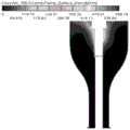
图5(a)-图5(c)对火花塞间隙置于预燃室内顶部的传统预燃室点火结构仿真效果图;Fig. 5(a)-Fig. 5(c) are simulation renderings of the ignition structure of the traditional pre-chamber with the spark plug gap placed on the top of the pre-chamber;
图6(a)-图6(c)本发明专利中火花塞间隙下移的预燃室点火结构仿真效果图;Fig. 6(a)-Fig. 6(c) Simulation renderings of the ignition structure of the pre-chamber with the spark plug gap moving down in the patent of the present invention;
图中,1、密封垫片,2、安装螺纹,3、预燃室独立进气喷射装置,4、火花塞间隙,5、预燃室,6、接地电极,7、连接通道,8、火花塞壳体,9、绝缘体,10、中心电极。In the figure, 1. Sealing gasket, 2. Mounting thread, 3. Independent intake injection device for pre-combustion chamber, 4. Spark plug gap, 5. Pre-combustion chamber, 6. Grounding electrode, 7. Connection channel, 8. Spark plug shell Body, 9, insulator, 10, center electrode.
具体实施方式Detailed ways
应该指出,以下详细说明都是例示性的,旨在对本申请提供进一步的说明。除非另有指明,本文使用的所有技术和科学术语具有与本申请所属技术领域的普通技术人员通常理解的相同含义。It should be pointed out that the following detailed description is exemplary and intended to provide further explanation to the present application. Unless defined otherwise, all technical and scientific terms used herein have the same meaning as commonly understood by one of ordinary skill in the art to which this application belongs.
需要注意的是,这里所使用的术语仅是为了描述具体实施方式,而非意图限制根据本申请的示例性实施方式。如在这里所使用的,除非上下文另外明确指出,否则单数形式也意图包括复数形式,此外,还应当理解的是,当在本说明书中使用术语“包含”和/或“包括”时,其指明存在特征、步骤、操作、器件、组件和/或它们的组合。It should be noted that the terminology used here is only for describing specific implementations, and is not intended to limit the exemplary implementations according to the present application. As used herein, unless the context clearly dictates otherwise, the singular is intended to include the plural, and it should also be understood that when the terms "comprising" and/or "comprising" are used in this specification, they mean There are features, steps, operations, means, components and/or combinations thereof.
正如背景技术所介绍的,现有预燃室点火系统技术中存在点火时能量浪费的问题,为了解决如上的技术问题,本申请提出了一种预燃室点火结构、系统及其工作方法。As introduced in the background technology, there is a problem of energy waste during ignition in the existing pre-chamber ignition system technology. In order to solve the above technical problems, this application proposes a pre-chamber ignition structure, system and working method.
本申请的一种典型的实施方式中,如图3所示,提供了一种预燃室点火结构,该一种预燃室点火结构中包括安装螺纹2、预燃室独立进气喷射装置3、火花塞间隙4、预燃室5、接地电极6、绝缘体9、中心电极10、连接通道7、密封垫片1、火花塞壳体8,所述的中心电极10、接地电极6伸入预燃室内部,火花塞间隙4是中心电极和接地电极端部之间的间隙。In a typical implementation of the present application, as shown in Figure 3, a pre-chamber ignition structure is provided, which includes a mounting
如图1所示,火花塞为发动机配件,在发动机缸盖上加工了火花塞的安装通道,在安装火花塞时,需要利用图2中火花塞壳体下部的安装螺纹与通道的内螺纹啮合,进而成功将火花塞安装在缸盖上。As shown in Figure 1, the spark plug is an engine accessory. The installation channel of the spark plug is processed on the engine cylinder head. The spark plug is mounted on the cylinder head.
如图3所示,所述接地电极固定在火花塞壳体下端。As shown in Figure 3, the ground electrode is fixed at the lower end of the spark plug housing.
本申请的另一种典型的实施方式中,如图4所示,所述接地电极也可焊接于预燃室内底部。In another typical implementation of the present application, as shown in FIG. 4 , the ground electrode may also be welded to the bottom of the pre-combustion chamber.
如图3、4所示,绝缘体具有沿轴线方向延伸的轴孔,中心电极插入上述绝缘体的轴孔并露出端部,所述接地电极伸出端和中心电极下端形成火花塞间隙,火花塞间隙距离预燃室上顶部的距离为L1,预燃室轴向长度为L0。As shown in Figures 3 and 4, the insulator has a shaft hole extending along the axial direction, the center electrode is inserted into the shaft hole of the insulator and exposes the end, the extended end of the ground electrode and the lower end of the center electrode form a spark plug gap, and the spark plug gap distance is preset The distance from the top of the combustion chamber is L1 , and the axial length of the pre-chamber is L0 .
本申请的再一种典型的实施方式中,提供了一种预燃室点火系统,包括上述预燃室点火结构,所述预燃室点火结构通过连接通道与主燃烧室相通。In yet another typical embodiment of the present application, a pre-chamber ignition system is provided, including the above-mentioned pre-chamber ignition structure, and the pre-chamber ignition structure communicates with the main combustion chamber through a connecting channel.
本发明在现有预燃室点火系统基础上,优化火花塞的火花塞间隙位置,改善火花塞放电后形成的点火位置,延长中心电极10,使其深入预燃室5内部,在其端部配置接地电极6,从而将改变火花塞间隙4在预燃室5内所处位置,火花塞间隙距离预燃室上顶部的距离L1优选为0.5L0<L1<0.75L0,L0为预燃室的轴向长度。中心电极10和接地电极6放电后,在两电极之间形成焰核,焰核温度上升至混合气燃点时,电极间隙附近的可燃混合气被点燃。由于此时发动机正处于压缩冲程,主燃烧室内混合气受活塞压缩作用,以较高速度经连接通道7进入预燃室5,在预燃室5中心轴线处形成向上的气流运动,预燃室5内下部的初始火焰随气流运动以较高速度向上传播,预燃室5上方未燃混合气被火焰前锋面包裹住并快速参与燃烧,预燃室5内燃烧压力、温度快速上升。与现有预燃室点火系统相比,该发明将使更多混合气参与预燃室5内燃烧,且在预燃室内形成的向上的气流运动加快了火焰传播速度,预燃室5内压力升高率增大,使预燃室5内获得更高的燃烧峰值压力,改善预燃室射流成分,增强预燃室射流强度。The present invention optimizes the spark plug gap position of the spark plug on the basis of the existing pre-combustion chamber ignition system, improves the ignition position formed after the spark plug discharges, extends the
预燃室5内火花塞放电点火后,迅速点燃了位于预燃室5内下部的火花塞间隙附近的混合气,形成的火焰前锋面在预燃室5内向上的气流运动作用下快速向上传播,预燃室内中上方的未燃混合气被火焰前锋面包裹住并快速参与燃烧,使预燃室5内有更多的混合气参与燃烧,预燃室内燃烧速度更快,燃烧压力、温度更高,大大减少了经连接通道7进入主燃烧室的预燃室射流中未燃混合气量,该预燃室射流中高能粒子和高温已燃气体所占比例更大,预燃室射流强度更高,从而保证该预燃室射流所具有的能量能够可靠点燃主燃烧室内稀混合气。After the spark plug in the
本发明点火后,预燃室5内向上的气流运动加快了预燃室5内火焰传播速度,并使更多混和气参与了预燃室5内的燃烧,使预燃室5内压力迅速上升,增大了预燃室5内压力升高率,加快了预燃室5内燃烧速度,进而提高了预燃室射流强度,使预燃室射流进入主燃烧室的流速加快,从而提高该预燃室射流进入主燃烧室后的射流贯穿距,增大了该预燃室射流在主燃烧室中形成的分布式多点点火覆盖面积,缩短了主燃烧室中火焰传播距离,加快了主燃烧室内燃烧速度,进而缩短了燃烧持续期,提高了燃烧热效率,使发动机工作循环波动降低,未燃HC和CO排放减少,显著提高了发动机工作稳定性。After the present invention is ignited, the upward airflow movement in the
为了更好的验证本申请的技术效果,本申请还公开了具体的仿真实例:In order to better verify the technical effect of the present application, the present application also discloses specific simulation examples:
AVL FIRE是专业的发动机性能仿真软件,能够准确地模拟发动机缸内流动和燃烧过程。运用AVL FIRE软件,对火花塞间隙置于预燃室内顶部的传统预燃室点火结构(case1)及本发明专利中火花塞间隙下移的预燃室点火结构(case2)进行了仿真对比分析。图5(a)-图5(c)及图6(a)-图6(c)是点火后预燃室内火焰面密度云图,表征了两种预燃室结构点火后,火焰在预燃室内的传播过程。case1中,如图5(a)-图5(c)所示,预燃室在上部点火后,火焰首先在预燃室内顶部扩散,然后再向下传播,在此过程中,预燃室内顶部压力较高,预燃室内下部混合气未参与燃烧便在该压力作用下经连接通道排出预燃室,因此前期进入主燃烧室的预燃室射流成分主要为未燃混合气,不具备点火能力,且此时预燃室内燃烧放热量少,预燃室射流能量弱。Case2中,如图6(a)-图6(c)所示,初始火核在预燃室内向上的气流运动作用下快速向预燃室上部发展,增大火焰传播面积的同时,包裹住预燃室内未燃混合气,使得预燃室内有更多的混合气参与燃烧,大大减少了预燃室射流中未燃混合气量,预燃室射流中高能粒子和高温已燃气体所占比例更大,显著提高了预燃室射流能量。AVL FIRE is a professional engine performance simulation software, which can accurately simulate the flow and combustion process in the engine cylinder. Using AVL FIRE software, the simulation comparison analysis was carried out on the traditional pre-combustion chamber ignition structure (case1) with the spark plug gap placed on the top of the pre-combustion chamber and the pre-combustion chamber ignition structure (case2) with the spark plug gap moved down in the patent of the present invention. Figure 5(a)-Figure 5(c) and Figure 6(a)-Figure 6(c) are the flame surface density cloud diagrams in the pre-combustion chamber after ignition, which characterizes the flame in the pre-combustion chamber after ignition of the two pre-combustion chamber structures the dissemination process. In case1, as shown in Figure 5(a)-Figure 5(c), after the upper part of the pre-chamber is ignited, the flame first spreads on the top of the pre-chamber, and then spreads downwards. During this process, the top of the pre-chamber The pressure is high, and the mixed gas in the lower part of the pre-combustion chamber is discharged from the pre-combustion chamber through the connecting channel under the action of the pressure without participating in the combustion. Therefore, the jet flow composition of the pre-combustion chamber entering the main combustion chamber in the early stage is mainly unburned mixed gas, which does not have the ability to ignite. , and at this time, the combustion heat release in the pre-combustion chamber is small, and the jet energy of the pre-chamber is weak. In
以上所述仅为本申请的优选实施例而已,并不用于限制本申请,对于本领域的技术人员来说,本申请可以有各种更改和变化。凡在本申请的精神和原则之内,所作的任何修改、等同替换、改进等,均应包含在本申请的保护范围之内。The above descriptions are only preferred embodiments of the present application, and are not intended to limit the present application. For those skilled in the art, various modifications and changes may be made to the present application. Any modifications, equivalent replacements, improvements, etc. made within the spirit and principles of this application shall be included within the protection scope of this application.
Claims (4)
Priority Applications (1)
| Application Number | Priority Date | Filing Date | Title |
|---|---|---|---|
| CN201810097971.0ACN108321678B (en) | 2018-01-31 | 2018-01-31 | A pre-combustion chamber ignition structure, system and working method thereof |
Applications Claiming Priority (1)
| Application Number | Priority Date | Filing Date | Title |
|---|---|---|---|
| CN201810097971.0ACN108321678B (en) | 2018-01-31 | 2018-01-31 | A pre-combustion chamber ignition structure, system and working method thereof |
Publications (2)
| Publication Number | Publication Date |
|---|---|
| CN108321678A CN108321678A (en) | 2018-07-24 |
| CN108321678Btrue CN108321678B (en) | 2019-10-15 |
Family
ID=62890398
Family Applications (1)
| Application Number | Title | Priority Date | Filing Date |
|---|---|---|---|
| CN201810097971.0AActiveCN108321678B (en) | 2018-01-31 | 2018-01-31 | A pre-combustion chamber ignition structure, system and working method thereof |
Country Status (1)
| Country | Link |
|---|---|
| CN (1) | CN108321678B (en) |
Families Citing this family (4)
| Publication number | Priority date | Publication date | Assignee | Title |
|---|---|---|---|---|
| JP7095570B2 (en)* | 2018-11-26 | 2022-07-05 | トヨタ自動車株式会社 | Internal combustion engine with sub-chamber |
| CN113882938B (en)* | 2021-09-28 | 2023-11-24 | 湖北华舜精冲技术有限公司 | Spiral vortex precombustion chamber ignition system |
| CN114961975A (en)* | 2022-05-31 | 2022-08-30 | 天津大学 | Engine pre-combustion device and engine pre-combustion system |
| CN117605565A (en)* | 2023-11-29 | 2024-02-27 | 河南柴油机重工有限责任公司 | Ignition type premixed combustion system of internal combustion engine |
Citations (4)
| Publication number | Priority date | Publication date | Assignee | Title |
|---|---|---|---|---|
| WO2001050017A1 (en)* | 1999-12-30 | 2001-07-12 | In Tae Johng | Ignition plug for internal combustion engines |
| CN103038960A (en)* | 2010-06-02 | 2013-04-10 | Mtu腓特烈港有限责任公司 | pre-chamber spark plug |
| CN105637216A (en)* | 2013-03-15 | 2016-06-01 | 伍德沃德有限公司 | Controlled spark ignited flame kernel flow |
| CN207218004U (en)* | 2017-09-21 | 2018-04-10 | 张蝶儿 | A kind of spark plug provided with precombustion chamber |
- 2018
- 2018-01-31CNCN201810097971.0Apatent/CN108321678B/enactiveActive
Patent Citations (4)
| Publication number | Priority date | Publication date | Assignee | Title |
|---|---|---|---|---|
| WO2001050017A1 (en)* | 1999-12-30 | 2001-07-12 | In Tae Johng | Ignition plug for internal combustion engines |
| CN103038960A (en)* | 2010-06-02 | 2013-04-10 | Mtu腓特烈港有限责任公司 | pre-chamber spark plug |
| CN105637216A (en)* | 2013-03-15 | 2016-06-01 | 伍德沃德有限公司 | Controlled spark ignited flame kernel flow |
| CN207218004U (en)* | 2017-09-21 | 2018-04-10 | 张蝶儿 | A kind of spark plug provided with precombustion chamber |
Also Published As
| Publication number | Publication date |
|---|---|
| CN108321678A (en) | 2018-07-24 |
Similar Documents
| Publication | Publication Date | Title |
|---|---|---|
| CN106014694B (en) | Air assisted gas injector, large-diameter gas machine precombustion chamber combustion system and method | |
| CN108321678B (en) | A pre-combustion chamber ignition structure, system and working method thereof | |
| US7659655B2 (en) | Pre-chamber spark plug | |
| US7922551B2 (en) | Pre-chamber spark plug | |
| CN109184898A (en) | A kind of marine large-diameter natural gas engine precombustion chamber multiple jet ignition type highly effective combustion system | |
| CN108331658B (en) | Gas supply system and method for improving frequency response of natural gas engine based on pre-combustion chamber enrichment | |
| CN110953067B (en) | Engine and double-jet combustion method thereof | |
| CN107332109A (en) | The spark plug and its internal combustion engine and automobile of a kind of flame | |
| CN108291476A (en) | Passive precombustion chamber lean direct injection | |
| CN107829816B (en) | A Combustion Chamber for Accelerating Flame Propagation and Suppressing Knock | |
| CN112814778A (en) | Air-assisted jet flame ignition device and ignition method thereof | |
| CN111485992A (en) | Engine rapid combustion device suitable for low-evaporation characteristic fuel | |
| CN110173341A (en) | A kind of ignition chamber type engine rotating jet combustion system | |
| CN108779702A (en) | Pre-chamber components | |
| CN116163847A (en) | Engine and control method thereof | |
| CN107091145A (en) | A kind of precombustion chamber of marine large-diameter gas engine | |
| CN110173343A (en) | A kind of engine ignition room jet stream collision burning system | |
| KR100400101B1 (en) | Ignition plug having multi-ignition pole | |
| CN207111228U (en) | With symmetrical spherical precombustion chamber dual fuel engine combustion chamber peculiar to vessel | |
| JPH0712037A (en) | Method and device for combustion of fuel in internal combustion engine | |
| CN106640360A (en) | Swirl combustion chamber of rotor engine | |
| CN105937462A (en) | Direct injection vortex piston top combustion chamber | |
| CN204827700U (en) | Engine piston | |
| CN201180580Y (en) | pre-chamber | |
| CN112177807A (en) | Method for realizing lean combustion of internal combustion engine |
Legal Events
| Date | Code | Title | Description |
|---|---|---|---|
| PB01 | Publication | ||
| PB01 | Publication | ||
| SE01 | Entry into force of request for substantive examination | ||
| SE01 | Entry into force of request for substantive examination | ||
| GR01 | Patent grant | ||
| GR01 | Patent grant |