CN108317011B - A natural gas pressure energy recovery system with integrated gas turbine - Google Patents
A natural gas pressure energy recovery system with integrated gas turbineDownload PDFInfo
- Publication number
- CN108317011B CN108317011BCN201810065171.0ACN201810065171ACN108317011BCN 108317011 BCN108317011 BCN 108317011BCN 201810065171 ACN201810065171 ACN 201810065171ACN 108317011 BCN108317011 BCN 108317011B
- Authority
- CN
- China
- Prior art keywords
- gas turbine
- heat exchanger
- heat
- gas
- natural gas
- Prior art date
- Legal status (The legal status is an assumption and is not a legal conclusion. Google has not performed a legal analysis and makes no representation as to the accuracy of the status listed.)
- Active
Links
Images
Classifications
- F—MECHANICAL ENGINEERING; LIGHTING; HEATING; WEAPONS; BLASTING
- F02—COMBUSTION ENGINES; HOT-GAS OR COMBUSTION-PRODUCT ENGINE PLANTS
- F02C—GAS-TURBINE PLANTS; AIR INTAKES FOR JET-PROPULSION PLANTS; CONTROLLING FUEL SUPPLY IN AIR-BREATHING JET-PROPULSION PLANTS
- F02C6/00—Plural gas-turbine plants; Combinations of gas-turbine plants with other apparatus; Adaptations of gas-turbine plants for special use
- F02C6/04—Gas-turbine plants providing heated or pressurised working fluid for other apparatus, e.g. without mechanical power output
- F02C6/06—Gas-turbine plants providing heated or pressurised working fluid for other apparatus, e.g. without mechanical power output providing compressed gas
- F—MECHANICAL ENGINEERING; LIGHTING; HEATING; WEAPONS; BLASTING
- F02—COMBUSTION ENGINES; HOT-GAS OR COMBUSTION-PRODUCT ENGINE PLANTS
- F02C—GAS-TURBINE PLANTS; AIR INTAKES FOR JET-PROPULSION PLANTS; CONTROLLING FUEL SUPPLY IN AIR-BREATHING JET-PROPULSION PLANTS
- F02C6/00—Plural gas-turbine plants; Combinations of gas-turbine plants with other apparatus; Adaptations of gas-turbine plants for special use
- F02C6/18—Plural gas-turbine plants; Combinations of gas-turbine plants with other apparatus; Adaptations of gas-turbine plants for special use using the waste heat of gas-turbine plants outside the plants themselves, e.g. gas-turbine power heat plants
- F—MECHANICAL ENGINEERING; LIGHTING; HEATING; WEAPONS; BLASTING
- F25—REFRIGERATION OR COOLING; COMBINED HEATING AND REFRIGERATION SYSTEMS; HEAT PUMP SYSTEMS; MANUFACTURE OR STORAGE OF ICE; LIQUEFACTION SOLIDIFICATION OF GASES
- F25B—REFRIGERATION MACHINES, PLANTS OR SYSTEMS; COMBINED HEATING AND REFRIGERATION SYSTEMS; HEAT PUMP SYSTEMS
- F25B30/00—Heat pumps
- F25B30/02—Heat pumps of the compression type
- F—MECHANICAL ENGINEERING; LIGHTING; HEATING; WEAPONS; BLASTING
- F25—REFRIGERATION OR COOLING; COMBINED HEATING AND REFRIGERATION SYSTEMS; HEAT PUMP SYSTEMS; MANUFACTURE OR STORAGE OF ICE; LIQUEFACTION SOLIDIFICATION OF GASES
- F25B—REFRIGERATION MACHINES, PLANTS OR SYSTEMS; COMBINED HEATING AND REFRIGERATION SYSTEMS; HEAT PUMP SYSTEMS
- F25B41/00—Fluid-circulation arrangements
- F25B41/30—Expansion means; Dispositions thereof
- Y—GENERAL TAGGING OF NEW TECHNOLOGICAL DEVELOPMENTS; GENERAL TAGGING OF CROSS-SECTIONAL TECHNOLOGIES SPANNING OVER SEVERAL SECTIONS OF THE IPC; TECHNICAL SUBJECTS COVERED BY FORMER USPC CROSS-REFERENCE ART COLLECTIONS [XRACs] AND DIGESTS
- Y02—TECHNOLOGIES OR APPLICATIONS FOR MITIGATION OR ADAPTATION AGAINST CLIMATE CHANGE
- Y02B—CLIMATE CHANGE MITIGATION TECHNOLOGIES RELATED TO BUILDINGS, e.g. HOUSING, HOUSE APPLIANCES OR RELATED END-USER APPLICATIONS
- Y02B30/00—Energy efficient heating, ventilation or air conditioning [HVAC]
- Y02B30/52—Heat recovery pumps, i.e. heat pump based systems or units able to transfer the thermal energy from one area of the premises or part of the facilities to a different one, improving the overall efficiency
Landscapes
- Engineering & Computer Science (AREA)
- Mechanical Engineering (AREA)
- General Engineering & Computer Science (AREA)
- Physics & Mathematics (AREA)
- Thermal Sciences (AREA)
- Chemical & Material Sciences (AREA)
- Combustion & Propulsion (AREA)
- Engine Equipment That Uses Special Cycles (AREA)
Abstract
Description
Translated fromChinese技术领域technical field
本发明涉及天然气管网压力能回收利用技术领域,特别涉及一种集成燃气轮机的天然气压力能回收系统。The invention relates to the technical field of recovery and utilization of natural gas pipeline network pressure energy, in particular to a natural gas pressure energy recovery system integrated with a gas turbine.
背景技术Background technique
目前对于天然气的长距离输送,普遍采用高压输送,例如西气东输一线、二线分别采用10MPa和12MPa的压力进行天然气输送,从而减少燃气输送的损失。上游的高压天然气先输送到大型用户和城市燃气前,根据不同用户需求进行降压,供给下游用户使用。天然气的调压方式一般采用减压阀对高压天然气进行节流膨胀降压,此过程无机械能输出,但存在温降,导致出站温度低于标准要求(>5℃)的供气温度,低温天然气甚至能产生霜冻堵塞阀门和管道,对调压及管道设备运行安全造成威胁。传统的解决方案是通过天然气加热器或电加热器对天然气进行加热。这不仅需要消耗燃气或电能,而且严重浪费天然气管网中的压力能。At present, for the long-distance transportation of natural gas, high-pressure transportation is generally used. For example, the first and second lines of the West-East Gas Pipeline use 10MPa and 12MPa pressure for natural gas transportation, thereby reducing the loss of gas transportation. The upstream high-pressure natural gas is first transported to large-scale users and city gas, and then depressurized according to the needs of different users, and supplied to downstream users. The pressure regulating method of natural gas generally uses a pressure reducing valve to throttle, expand and depressurize the high-pressure natural gas. There is no mechanical energy output in this process, but there is a temperature drop, which causes the exit temperature to be lower than the gas supply temperature required by the standard (>5°C), and the low temperature Natural gas can even generate frost and block valves and pipelines, posing a threat to the safety of pressure regulation and pipeline equipment. The traditional solution is to heat natural gas with natural gas heaters or electric heaters. This not only needs to consume gas or electricity, but also wastes the pressure energy in the natural gas pipeline network seriously.
因而现有技术还有待改进和提高。Therefore, the existing technology still needs to be improved and improved.
发明内容SUMMARY OF THE INVENTION
鉴于现有技术的不足,本发明所要解决的技术问题是要一种集成燃气轮机的天然气压力能回收系统,以达到高效回收天然气压力能、提高发电系统的发电效率和能量利用效率的效果。In view of the deficiencies of the prior art, the technical problem to be solved by the present invention is a natural gas pressure energy recovery system integrated with a gas turbine, so as to achieve the effects of efficiently recovering the natural gas pressure energy and improving the power generation efficiency and energy utilization efficiency of the power generation system.
为了解决上述技术问题,本发明所采用的技术方案如下:In order to solve the above-mentioned technical problems, the technical scheme adopted in the present invention is as follows:
一种集成燃气轮机的天然气压力能回收系统,其包括:膨胀热泵模块、换热模块以及燃气轮机模块;所述换热模块包括第一换热器和第二换热器,所述燃气轮机模块包括依次连接的燃气轮机以及烟气回收装置;所述膨胀热泵模块、第一换热器以第二换热器通过管路依次连接于高压管网与低压管网之间;所述第一换热器与燃气轮机循环连接,所述第二换热器与所述烟气回收装置循环连接。A natural gas pressure energy recovery system integrated with a gas turbine, comprising: an expansion heat pump module, a heat exchange module and a gas turbine module; the heat exchange module includes a first heat exchanger and a second heat exchanger, and the gas turbine module includes sequentially connected a gas turbine and a flue gas recovery device; the expansion heat pump module, the first heat exchanger and the second heat exchanger are sequentially connected between the high-pressure pipe network and the low-pressure pipe network through pipelines; the first heat exchanger and the gas turbine A cyclic connection, the second heat exchanger is cyclically connected to the flue gas recovery device.
所述集成燃气轮机的天然气压力能回收系统,其中,所述第二换热管程出口设置第一支路和第二支路,所述第二换热管通过第一支路与低压管网相连接,并通过第二支路与燃气轮机相连接,以为燃气轮机提供燃料。The natural gas pressure energy recovery system of the integrated gas turbine, wherein a first branch and a second branch are arranged at the outlet of the second heat exchange tube side, and the second heat exchange tube is connected to the low-pressure pipe network through the first branch. connected with the gas turbine through the second branch to provide fuel for the gas turbine.
所述集成燃气轮机的天然气压力能回收系统,其中,所述燃气轮机通过管路分别与第一换热器的第一壳程进口和第一壳程出口相连接,所述燃气轮机与第一换热器之间的循环介质通过第一壳程进口进入第一换热器,并与流经第一换热器的低压天然气进行热交换,放热后的循环介质通过第一壳程出口回流至燃气轮机。The natural gas pressure energy recovery system of the integrated gas turbine, wherein the gas turbine is respectively connected to the first shell side inlet and the first shell side outlet of the first heat exchanger through pipelines, and the gas turbine is connected to the first heat exchanger. The circulating medium between them enters the first heat exchanger through the first shell side inlet, and exchanges heat with the low-pressure natural gas flowing through the first heat exchanger, and the circulating medium after heat release returns to the gas turbine through the first shell side outlet.
所述集成燃气轮机的天然气压力能回收系统,其中,所述烟气回收装置通过管路分别与第二换热的第二壳程进口和第二壳程出口相连接,第二换热与烟气回收装置之间的循环介质通过第二壳程进口进入第二换热器,并与流经第二换热器的低压天然气进行热交换,放热后的循环介质通过第二壳程出口回流至烟气回收装置,以与燃气轮机排出的烟气换热。The natural gas pressure energy recovery system of the integrated gas turbine, wherein the flue gas recovery device is respectively connected to the second shell side inlet and the second shell side outlet of the second heat exchange through pipelines, and the second heat exchange is connected to the flue gas. The circulating medium between the recovery devices enters the second heat exchanger through the second shell side inlet, and exchanges heat with the low-pressure natural gas flowing through the second heat exchanger. A flue gas recovery device to exchange heat with the flue gas discharged from the gas turbine.
所述集成燃气轮机的天然气压力能回收系统,其中,所述烟气回收装置采用烟气走管外、循环介质走管内的鳍片管式烟气废热回收器。In the natural gas pressure energy recovery system of the integrated gas turbine, wherein, the flue gas recovery device adopts a fin-tube type flue gas waste heat recovery device that runs outside the flue gas pipe and inside the circulating medium pipe.
所述集成燃气轮机的天然气压力能回收系统,其中,所述第一换热器与燃气轮机的循环管路上设置有第一电动泵和第一补料管;所述第二换热器与烟气回收装置的循环管路上设置有第二电动泵和第二补料管。The natural gas pressure energy recovery system of the integrated gas turbine, wherein a first electric pump and a first feed pipe are arranged on the circulation pipeline between the first heat exchanger and the gas turbine; the second heat exchanger and the flue gas recovery A second electric pump and a second feeding pipe are arranged on the circulating pipeline of the device.
所述集成燃气轮机的天然气压力能回收系统,其中,所述第一换热器和第二换热器均采用循环介质走管外、天然气走管内的列管式换热器。In the natural gas pressure energy recovery system of the integrated gas turbine, wherein, the first heat exchanger and the second heat exchanger both adopt a tubular heat exchanger in which the circulating medium runs outside the pipe and the natural gas runs inside the pipe.
所述集成燃气轮机的天然气压力能回收系统,其中,所述膨胀热泵模块包括:膨胀机,以及循环连接的压缩机、空气加热器以及蒸发器,所述压缩机与所述膨胀机联轴设置,所述空气加热器壳程出口与燃气轮机的燃料进口连接。The natural gas pressure energy recovery system with integrated gas turbine, wherein the expansion heat pump module comprises: an expander, and a cyclically connected compressor, an air heater and an evaporator, the compressor and the expander are arranged in a coupling shaft, The air heater shell side outlet is connected to the fuel inlet of the gas turbine.
所述集成燃气轮机的天然气压力能回收系统,其中,所述膨胀热泵模块的循环介质为氟利昂。In the natural gas pressure energy recovery system of the integrated gas turbine, wherein the circulating medium of the expansion heat pump module is Freon.
所述集成燃气轮机的天然气压力能回收系统,其中,所述膨胀热泵模块集成在一个撬内。The natural gas pressure energy recovery system of the integrated gas turbine, wherein the expansion heat pump module is integrated in a skid.
有益效果:与现有技术相比,本发明提供了一种集成燃气轮机的天然气压力能回收系统,其包括膨胀热泵模块,换热模块以及燃气轮机模块,所述膨胀热泵模块将膨胀机及热泵联用,实现了压力能膨胀联动热泵结构,以利用膨胀机提供机械能带动热泵运转加热空气,有效提高燃气轮机的发电效率。同时,换热模块对燃气轮机的润滑油进行冷却以及回收烟气回收装置内烟气的余热,这样一方面充分利用低温天然气的冷能;另一方面提高了能源利用效率高。Beneficial effects: Compared with the prior art, the present invention provides a natural gas pressure energy recovery system integrated with a gas turbine, which includes an expansion heat pump module, a heat exchange module and a gas turbine module, and the expansion heat pump module combines the expander and the heat pump. , the pressure energy expansion linkage heat pump structure is realized, and the mechanical energy provided by the expander is used to drive the heat pump to operate and heat the air, which effectively improves the power generation efficiency of the gas turbine. At the same time, the heat exchange module cools the lubricating oil of the gas turbine and recovers the waste heat of the flue gas in the flue gas recovery device, so on the one hand, the cold energy of the low-temperature natural gas is fully utilized; on the other hand, the energy utilization efficiency is improved.
附图说明Description of drawings
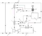
图1为本发明提供的集成燃气轮机的天然气压力能回收系统较佳实施的结构示意图。FIG. 1 is a schematic structural diagram of a preferred implementation of a natural gas pressure energy recovery system with an integrated gas turbine provided by the present invention.
具体实施方式Detailed ways
本发明提供一种集成燃气轮机的天然气压力能回收系统,为使本发明的目的、技术方案及效果更加清楚、明确,以下参照附图并举实施例对本发明进一步详细说明。应当理解,此处所描述的具体实施例仅用以解释本发明,并不用于限定本发明。The present invention provides a natural gas pressure energy recovery system integrated with a gas turbine. In order to make the purpose, technical solutions and effects of the present invention clearer and clearer, the present invention is further described in detail below with reference to the accompanying drawings and examples. It should be understood that the specific embodiments described herein are only used to explain the present invention, but not to limit the present invention.
下面结合附图,通过对实施例的描述,对发明内容作进一步说明。In the following, the content of the invention will be further illustrated by describing the embodiments with reference to the accompanying drawings.
请参照图1,图1为本发明提供的集成燃气轮机的天然气压力能回收系统的结构示意图。Please refer to FIG. 1 , which is a schematic structural diagram of a natural gas pressure energy recovery system with an integrated gas turbine provided by the present invention.
所述集成燃气轮机的天然气压力能回收系统,其包括膨胀热泵模块、换热模块以及燃气轮机模块;所述换热模块包括第一换热器6和第二换热器10,所述燃气轮机模块包括依次连接的燃气轮机9以及烟气回收装置12;所述膨胀热泵模块、第一换热器6以第二换热器10通过管路依次连接于高压管网与低压管网之间;所述第一换热器6与燃气轮机9循环连接,所述第二换热器10与所述烟气回收装置12循环连接。本实施例通过压力能膨胀联动热泵系统、第一换热器和燃气轮机构成的润滑油冷却系统、以及第二换热器和烟气回收装置把压力能利用和燃气轮机发电整合在一起,实现了高效回收天然气压力能,同时提高了发电系统的发电效率和能量利用效率。The natural gas pressure energy recovery system with integrated gas turbine includes an expansion heat pump module, a heat exchange module and a gas turbine module; the heat exchange module includes a first heat exchanger 6 and a second heat exchanger 10, and the gas turbine module includes sequentially The connected gas turbine 9 and the flue gas recovery device 12; the expansion heat pump module, the first heat exchanger 6 and the second heat exchanger 10 are sequentially connected between the high-pressure pipe network and the low-pressure pipe network through pipelines; the first The heat exchanger 6 is cyclically connected to the gas turbine 9 , and the second heat exchanger 10 is cyclically connected to the flue gas recovery device 12 . This embodiment integrates pressure energy utilization and gas turbine power generation through a pressure energy expansion linked heat pump system, a lubricating oil cooling system composed of a first heat exchanger and a gas turbine, a second heat exchanger and a flue gas recovery device, and achieves high efficiency The natural gas pressure energy is recovered, and the power generation efficiency and energy utilization efficiency of the power generation system are improved at the same time.
所述膨胀热泵模块包括膨胀机2、压缩机3、空气加热器6以及蒸发器4;所述膨胀机2与所述压缩机3同轴设置,所述压缩机3出口与空气加热器6的管程入口相连接,所述空气加热器6的管程出口与蒸发器4的入口相连接,所述蒸发器4的出口与压缩机3入口相连接,所述空温加热器6的壳程出口与燃气轮机9的燃料进口连接。所述压缩机3在膨胀机2的带动下将进入其内的第二循环介质进行压缩,压缩后的第二循环介质进入空气加热器6,与流经空气加热器6的空气进行热交换,放热后的第二循环介质液化为液态,液态的第二循环介质进入蒸发器4,通过所述蒸发器4吸热汽化,汽化后的第二循环介质流入压缩机3。在本实施中,所述膨胀机2之前的高压管网上设置有第一电磁阀1,通过所第一电磁阀1控制流入膨胀机2的天然气的流量。在实际应用中,所述膨胀热泵模块可高度集成在一个撬内。The expansion heat pump module includes an expander 2, a compressor 3, an air heater 6 and an evaporator 4; the expander 2 and the compressor 3 are coaxially arranged, and the outlet of the compressor 3 is connected to the outlet of the air heater 6. The tube side inlet is connected, the tube side outlet of the air heater 6 is connected with the inlet of the evaporator 4, the outlet of the evaporator 4 is connected with the compressor 3 inlet, and the shell side of the air temperature heater 6 is connected. The outlet is connected to the fuel inlet of the gas turbine 9 . The compressor 3 is driven by the expander 2 to compress the second circulating medium entering it, and the compressed second circulating medium enters the air heater 6 and exchanges heat with the air flowing through the air heater 6, The exothermic second circulating medium is liquefied into a liquid state, and the liquid second circulating medium enters the evaporator 4 , absorbs heat and vaporizes through the evaporator 4 , and the vaporized second circulating medium flows into the compressor 3 . In this implementation, a first solenoid valve 1 is provided on the high-pressure pipeline network before the expander 2 , and the flow of natural gas flowing into the expander 2 is controlled by the first solenoid valve 1 . In practical applications, the expansion heat pump module can be highly integrated in a skid.
进一步,所述膨胀热泵模块还可以包括节流阀5,所述节流阀5设置于空气加热器6与蒸发器4之间的管路上,所述空气加热器6的管程出口流出的液体第二循环介质在节流阀5处节流成低温低压液体。在本实施例中,所述第二循环介质优选为工质氟利昂。Further, the expansion heat pump module may also include a throttle valve 5, the throttle valve 5 is arranged on the pipeline between the air heater 6 and the evaporator 4, and the liquid flowing out of the tube side outlet of the air heater 6 The second circulating medium is throttled into a low temperature and low pressure liquid at the throttle valve 5 . In this embodiment, the second circulating medium is preferably a working medium Freon.
所述第一换热器7可以采用循环介质管外、天然气走管内的列管式换热器。所述第一换热器7的管程入口与膨胀机2相连接,其管程出口与第二换热器10相连接,其壳程出口与燃气轮机9的发电机的入口相连接,其壳程入口与燃气轮机9的发电机出口相连接。所述第一换热器7与燃气轮机9之间形成燃气轮机的润滑油冷却系统,通过所述润滑油冷却系统通过其内循环的第三循环介质对燃气轮机9的发电机的润滑油进行冷却,以对天然气的冷能进行回收。也就是说,所述燃气轮机9的高温润滑油与流经第一换热器7的第三循环介质进行热交换,通过第三循环介质对其进行降温,流经燃气轮机9的第三循环机制通过第一换热器7的壳程入口流入第一换热器7,与流经第一换热器7低温天然气进行热交换,将热量释放给低温天然气,放热后的第三循环介质回流至燃气轮机从而通过低温天然气对润滑油进行冷却,回收低温天然气携带的冷能,提高了能源的利用率。The first heat exchanger 7 can be a tubular heat exchanger outside the circulating medium pipe and inside the natural gas pipe. The tube-side inlet of the first heat exchanger 7 is connected to the expander 2, its tube-side outlet is connected to the second heat exchanger 10, its shell-side outlet is connected to the inlet of the generator of the gas turbine 9, and its shell-side outlet is connected to the inlet of the generator of the gas turbine 9. The process inlet is connected to the generator outlet of the gas turbine 9 . A lubricating oil cooling system of the gas turbine is formed between the first heat exchanger 7 and the gas turbine 9, and the lubricating oil of the generator of the gas turbine 9 is cooled by the third circulating medium circulating in the lubricating oil cooling system to cool the lubricating oil of the generator of the gas turbine 9. The cold energy of natural gas is recovered. That is to say, the high-temperature lubricating oil of the gas turbine 9 exchanges heat with the third circulating medium flowing through the first heat exchanger 7, and the temperature is lowered by the third circulating medium, and the third circulating mechanism flowing through the gas turbine 9 passes through The shell side inlet of the first heat exchanger 7 flows into the first heat exchanger 7, conducts heat exchange with the low-temperature natural gas flowing through the first heat exchanger 7, releases the heat to the low-temperature natural gas, and the third circulating medium after heat release returns to the low-temperature natural gas. The gas turbine thus cools the lubricating oil through the low-temperature natural gas, recovers the cold energy carried by the low-temperature natural gas, and improves the utilization rate of energy.
进一步,所述润滑油冷却系统还包括第一电动泵8和第一补料管,所述第一补料管上设置有第三电磁阀15。所述第一电动泵8位于所述第一换热器7的壳程出口与燃气轮机9的发电机入口之间的管路上,通过所述第一电动泵8将流经所述第一换热器7内的第三循环介质泵入燃气轮机9的发电机内,实现了润滑油冷却系统中第三循环介质的流量的可控性。其中,所述第三循环介质优选为去盐水。Further, the lubricating oil cooling system further includes a first electric pump 8 and a first feeding pipe, and a third solenoid valve 15 is arranged on the first feeding pipe. The first electric pump 8 is located on the pipeline between the shell side outlet of the first heat exchanger 7 and the generator inlet of the gas turbine 9, and the first electric pump 8 will flow through the first heat exchange The third circulating medium in the generator 7 is pumped into the generator of the gas turbine 9, so as to realize the controllability of the flow rate of the third circulating medium in the lubricating oil cooling system. Wherein, the third circulating medium is preferably demineralized water.
所述第二换热器10也可采用循环介质走管外、天然气走管内的列管式换热器。所述第二换热器10的管程出口处设置有两个支路,分别为第一支路和第二支路;所述第一支路与低压管网相连接,以为下游用户提供天然气;第二支路与燃气轮机9的燃料入口相连接,以为燃气轮机9提供燃料。所述第二支路上设置有第二电磁阀13,通过所述第二电磁阀13控制流入燃气轮机的天然气的流量。The second heat exchanger 10 may also be a tubular heat exchanger in which the circulating medium runs outside the pipe and the natural gas runs inside the pipe. There are two branches at the tube exit of the second heat exchanger 10, namely the first branch and the second branch; the first branch is connected with the low-pressure pipe network to provide natural gas for downstream users ; The second branch is connected to the fuel inlet of the gas turbine 9 to provide fuel for the gas turbine 9 . A second solenoid valve 13 is provided on the second branch, and the flow of natural gas flowing into the gas turbine is controlled by the second solenoid valve 13 .
进一步,所述第二换热器10与所述烟气回收装置12相连接,利用烟气回收装置12内的高温烟气对流经第二换热器10的天然气进行复热,以提高低压管网的天然气的温度,实现了高温烟气的余热回收,提高了能源的利用率。相应的,所述第二换热器10与所述烟气回收装置12形成烟气余热回收系统,在所述烟气余热回收系统中,所述第二换热器10的壳程入口与烟气回收装置12的出气相连通,所述第二换热器10的壳程出口与烟气回收装置12的入口相连通,使得烟气余热回收系统的第一循环介质在所述第二换热器10与烟气回收装置12之间循环流动。在本实施例中,所述第一循环介质为去盐水,所述去盐水流入烟气回收装置12后,吸收烟气回收装置内高温烟气的热量,吸热后的去盐水流入第二换热器10,与流经第二换热器10的天然气进行热交换,为其提供热源以复热流经第二换热器10的天然气。Further, the second heat exchanger 10 is connected to the flue gas recovery device 12, and the high-temperature flue gas in the flue gas recovery device 12 is used to reheat the natural gas flowing through the second heat exchanger 10, so as to improve the low-pressure pipe The temperature of the natural gas in the network is realized, the waste heat recovery of the high-temperature flue gas is realized, and the utilization rate of energy is improved. Correspondingly, the second heat exchanger 10 and the flue gas recovery device 12 form a flue gas waste heat recovery system. In the flue gas waste heat recovery system, the shell side inlet of the second heat exchanger 10 and the flue gas waste heat recovery system The outlet gas phase of the gas recovery device 12 is communicated, and the shell side outlet of the second heat exchanger 10 is communicated with the inlet of the flue gas recovery device 12, so that the first circulating medium of the flue gas waste heat recovery system is in the second heat exchange. Circulate flow between the device 10 and the flue gas recovery device 12 . In this embodiment, the first circulating medium is demineralized water. After the demineralized water flows into the flue gas recovery device 12, it absorbs the heat of the high-temperature flue gas in the flue gas recovery device, and the demineralized water after absorbing heat flows into the second exchange The heat exchanger 10 exchanges heat with the natural gas flowing through the second heat exchanger 10 to provide a heat source for reheating the natural gas flowing through the second heat exchanger 10 .
进一步,所述烟气余热回收系统还包括第二电动泵11和第二补料管,所述第二补料管上设置有第四电磁阀16。所述第二电动泵11位于所述第二换热器10的壳程出口与烟气回收装置12入口之间的管路上,通过所述第二电动泵11将所述第二换热器10内的第一循环介质泵入烟气回收装置12,实现了烟气余热回收系统中的第一循环介质流量的可控性。在本实施例中,所述烟气回收装置12采用烟气走管外、第一循环介质走管内的鳍片管式烟气废热回收器。Further, the flue gas waste heat recovery system further includes a second electric pump 11 and a second feed pipe, and the second feed pipe is provided with a fourth solenoid valve 16 . The second electric pump 11 is located on the pipeline between the shell side outlet of the second heat exchanger 10 and the inlet of the flue gas recovery device 12 . The first circulating medium inside is pumped into the flue gas recovery device 12 to realize the controllability of the flow rate of the first circulating medium in the flue gas waste heat recovery system. In this embodiment, the flue gas recovery device 12 adopts a fin tube type flue gas waste heat recovery device outside the flue gas pipe and inside the first circulating medium pipe.
本实施例提供的集成燃气轮机的天然气压力能回收系统其工作过程具体可以为:The specific working process of the natural gas pressure energy recovery system of the integrated gas turbine provided in this embodiment can be as follows:
首先,高于4MPa高压管网的天然气通过第一电磁阀1后进入膨胀机2膨胀降压,低温天然气经第一换热器7和第二换热器10回温后,分成两路,一路直接进入下游中低压管网,另一路经过第二电磁阀13进入燃气轮机9的燃烧室燃烧做功,从而驱动发电机发电。其中,所述膨胀机2联轴驱动压缩机3,工质氟利昂经过蒸发器4吸热气化后,通过压缩机3压缩成高压高温蒸汽,然后进入空气加热器6,与空气进行换热,加热空气,并在节流阀5处节流成低温低压液体,完成制热循环;第一换热器7将流入其内的低温天然气与流入其内的去盐水进行热交换,通过去盐水对低温天然气进行复热,并使得去盐水吸收低温天然气的冷能,降温后的去盐水通过第一电动泵输入燃气轮机9的发电机,并与燃气轮机9的发电机内的润滑油进行热交换,吸收润滑油的热能以冷却所述润滑油;所述第二换热器10将流入其内的低温天然气与流入其内的去盐水进行热交换,通过去盐水对低温天然气进行复热,并使得去盐水吸收低温天然气的冷能,降温后的去盐水通过第二电动泵11输入烟气回收装置12,并与烟气回收装置12内的高温烟气进行热交换,回收高温烟气的热量。First, the natural gas with high pressure higher than 4MPa passes through the first solenoid valve 1 and then enters the expander 2 for expansion and pressure reduction. It directly enters the downstream medium and low pressure pipeline network, and the other way enters the combustion chamber of the gas turbine 9 through the second solenoid valve 13 to perform work, thereby driving the generator to generate electricity. Wherein, the expander 2 is coupled to drive the compressor 3, and the working fluid Freon is compressed into high-pressure high-temperature steam by the compressor 3 after heat absorption and gasification by the evaporator 4, and then enters the air heater 6 to exchange heat with the air, Heating the air, and throttling it into a low-temperature and low-pressure liquid at the throttle valve 5 to complete the heating cycle; The low-temperature natural gas is reheated, and the demineralized natural gas is made to absorb the cold energy of the low-temperature natural gas, and the demineralized water after cooling is input into the generator of the gas turbine 9 through the first electric pump, and exchanges heat with the lubricating oil in the generator of the gas turbine 9 to absorb The heat energy of the lubricating oil is used to cool the lubricating oil; the second heat exchanger 10 exchanges the heat of the low-temperature natural gas flowing into it with the demineralized water flowing into it, reheats the low-temperature natural gas through the demineralized water, and makes the demineralized natural gas. The brine absorbs the cold energy of the low-temperature natural gas, and the de-salted water after cooling is input to the flue gas recovery device 12 through the second electric pump 11, and exchanges heat with the high-temperature flue gas in the flue gas recovery device 12 to recover the heat of the high-temperature flue gas.
下面为了说明本发明提供的集成燃气轮机的天然气压力能回收系统饿工作过程,以某小型调压站为例,该站调压流量为2000 Nm3/h,调压规模为6MPa至1.6MPa,天然气初始温度约为20℃。In order to illustrate the working process of the natural gas pressure energy recovery system of the integrated gas turbine provided by the present invention, take a small pressure regulating station as an example, the pressure regulating flow of this station is 2000 Nm3/h, the pressure regulating scale is 6MPa to 1.6MPa, The temperature is about 20°C.
所述集成燃气轮机的天然气压力能回收系统的工作过程具体为:满足城市管网瞬时需求量1450 kg/h的天然气,压力6MPa、温度20℃,通过第一电磁阀1后进入膨胀机2膨胀降压到1.6MPa,温度为-44℃。低温天然气经第一换热器7和第二换热器10回温到0℃以上,然后分成两路,一路直接进入下游中低压燃气管网,另一路经过第二电磁阀13进入燃气轮机9的燃烧室燃烧做功,从而驱动发电机发电;其中,高压天然气通过膨胀机2膨胀将压力能转化成机械能,输出约30kw的机械能,热泵系统COP取3.0,经计算热泵系统能提供90kw的热量。The working process of the natural gas pressure energy recovery system with integrated gas turbine is as follows: the natural gas that meets the instantaneous demand of the urban pipeline network of 1450 kg/h, the pressure is 6 MPa and the temperature is 20 °C, passes through the first solenoid valve 1 and then enters the expander 2 to expand and drop. Pressure to 1.6MPa, the temperature is -44 ℃. The low-temperature natural gas is returned to a temperature above 0°C through the first heat exchanger 7 and the second heat exchanger 10, and then divided into two paths, one path directly enters the downstream medium and low pressure gas pipeline network, and the other path enters the gas turbine 9 through the second solenoid valve 13. The combustion chamber burns to do work, thereby driving the generator to generate electricity; wherein, the high-pressure natural gas is expanded by the expander 2 to convert the pressure energy into mechanical energy, and output about 30kw of mechanical energy.
最后应说明的是:以上实施例仅用以说明本发明的技术方案,而非对其限制;尽管参照前述实施例对本发明进行了详细的说明,本领域的普通技术人员应当理解:其依然可以对前述各实施例所记载的技术方案进行修改,或者对其中部分技术特征进行等同替换;而这些修改或者替换,并不使相应技术方案的本质脱离本发明各实施例技术方案的精神和范围。Finally, it should be noted that the above embodiments are only used to illustrate the technical solutions of the present invention, but not to limit them; although the present invention has been described in detail with reference to the foregoing embodiments, those of ordinary skill in the art should understand that it can still be The technical solutions described in the foregoing embodiments are modified, or some technical features thereof are equivalently replaced; and these modifications or replacements do not make the essence of the corresponding technical solutions deviate from the spirit and scope of the technical solutions of the embodiments of the present invention.
Claims (8)
Translated fromChinesePriority Applications (1)
| Application Number | Priority Date | Filing Date | Title |
|---|---|---|---|
| CN201810065171.0ACN108317011B (en) | 2018-01-23 | 2018-01-23 | A natural gas pressure energy recovery system with integrated gas turbine |
Applications Claiming Priority (1)
| Application Number | Priority Date | Filing Date | Title |
|---|---|---|---|
| CN201810065171.0ACN108317011B (en) | 2018-01-23 | 2018-01-23 | A natural gas pressure energy recovery system with integrated gas turbine |
Publications (2)
| Publication Number | Publication Date |
|---|---|
| CN108317011A CN108317011A (en) | 2018-07-24 |
| CN108317011Btrue CN108317011B (en) | 2020-08-25 |
Family
ID=62888140
Family Applications (1)
| Application Number | Title | Priority Date | Filing Date |
|---|---|---|---|
| CN201810065171.0AActiveCN108317011B (en) | 2018-01-23 | 2018-01-23 | A natural gas pressure energy recovery system with integrated gas turbine |
Country Status (1)
| Country | Link |
|---|---|
| CN (1) | CN108317011B (en) |
Families Citing this family (3)
| Publication number | Priority date | Publication date | Assignee | Title |
|---|---|---|---|---|
| CN110230517A (en)* | 2019-06-06 | 2019-09-13 | 上海航天智慧能源技术有限公司 | A kind of moveable cold energy generation vehicle of modularization |
| CN110966060A (en)* | 2019-11-21 | 2020-04-07 | 深圳市燃气集团股份有限公司 | Pipeline pressure energy and natural gas distributed energy coupling system |
| CN110953069A (en)* | 2019-12-17 | 2020-04-03 | 中国能源建设集团广东省电力设计研究院有限公司 | Multi-energy coupling power generation system of gas turbine power station |
Family Cites Families (7)
| Publication number | Priority date | Publication date | Assignee | Title |
|---|---|---|---|---|
| CN2087693U (en)* | 1990-12-14 | 1991-10-30 | 北京市西城区新开通用试验厂 | Combined power device for treating natural gas |
| CN104929776A (en)* | 2015-05-29 | 2015-09-23 | 浙江浙能节能科技有限公司 | Combined cycle power generation system utilizing gas and natural gas pipe network pressure energy |
| CN204829239U (en)* | 2015-07-01 | 2015-12-02 | 上海电力学院 | Be arranged in natural gas pressure energy recovery system turboexpander lubricating oil cooling system |
| CN105114131A (en)* | 2015-08-31 | 2015-12-02 | 北京市燃气集团有限责任公司 | Integrated device capable of achieving expansion power generation and compression refrigeration through natural gas pressure |
| CN105888845B (en)* | 2016-06-12 | 2018-05-08 | 华电郑州机械设计研究院有限公司 | A kind of natural gas differential pressure cold energy utilization device |
| CN106523920B (en)* | 2016-12-01 | 2019-04-09 | 深圳市燃气集团股份有限公司 | A kind of pipe network pressure energy method and device using turbo-expander |
| CN206785443U (en)* | 2017-05-12 | 2017-12-22 | 四川宏达石油天然气工程有限公司 | A kind of high-pressure natural gas cogeneration distributed energy resource system |
- 2018
- 2018-01-23CNCN201810065171.0Apatent/CN108317011B/enactiveActive
Also Published As
| Publication number | Publication date |
|---|---|
| CN108317011A (en) | 2018-07-24 |
Similar Documents
| Publication | Publication Date | Title |
|---|---|---|
| CN109826685B (en) | Supercritical carbon dioxide circulating coal-fired power generation system and method | |
| CN111022138B (en) | A supercritical carbon dioxide power generation system based on absorption heat pump waste heat recovery | |
| CN109098809B (en) | An ORC power generation system using LNG cold energy and industrial waste heat with a heat recovery cycle | |
| CN102878603A (en) | Gas-steam circulation combined double-stage coupling heat pump heat supply device | |
| CN114776411B (en) | Integrated heat storage coal-fired power generation system and working method | |
| CN106895603A (en) | Compression/absorb enclosed parallel connection composite fuel gas heat pump operation method | |
| CN109944651A (en) | A medium-low temperature waste heat-driven flash evaporation-absorption combined cycle power-cooling combined supply system | |
| CN108533344B (en) | Nested LNG two-stage parallel cold energy power generation and ice making method and system thereof | |
| CN112554983A (en) | Liquid carbon dioxide energy storage system and method coupled with kalina cycle | |
| CN110230523B (en) | A supercritical CO2 power generation system and method coupled with seawater desalination | |
| CN114483232B (en) | Compressed air energy storage system based on organic flash evaporation circulation and control method | |
| CN108317011B (en) | A natural gas pressure energy recovery system with integrated gas turbine | |
| CN110905618A (en) | Internal combustion engine cogeneration waste heat recovery system for distributed energy systems | |
| CN214741510U (en) | Waste heat auxiliary heating condensate system for supercritical carbon dioxide circulation cold end | |
| CN114135398A (en) | A gas turbine combined cycle power generation system and method in a distributed energy environment | |
| CN111396291A (en) | Compressed gas waste heat recovery power generation system | |
| CN108771950A (en) | A kind of carbon dioxide recycle electricity generation system and method being pressurized using chemical absorbing | |
| CN115929431A (en) | Strong-flexibility coal-fired power generation system and operation method | |
| CN108331627B (en) | Single-cycle two-stage LNG cold energy power generation and ice making method and system | |
| CN112112694A (en) | Liquid air energy storage system and method for self-consumption of heat of compression | |
| CN117514403A (en) | A waste heat-driven compressed steam energy storage and recycling method | |
| CN114922705B (en) | System and method for circulating split-flow repressing supercritical carbon dioxide | |
| CN116464525A (en) | Integrated heat storage supercritical carbon dioxide coal-fired power generation system and operation method | |
| CN208040469U (en) | Single cycle twin-stage LNG cold energy generations and ice maker | |
| CN113309591A (en) | LNG cold energy utilization device |
Legal Events
| Date | Code | Title | Description |
|---|---|---|---|
| PB01 | Publication | ||
| PB01 | Publication | ||
| SE01 | Entry into force of request for substantive examination | ||
| SE01 | Entry into force of request for substantive examination | ||
| GR01 | Patent grant | ||
| GR01 | Patent grant | ||
| TR01 | Transfer of patent right | Effective date of registration:20250818 Address after:523000 Guangdong Province Dongguan City Gaoxia Town Gaoxia Tangxia Chuanfu Street 13 No. Patentee after:Dongguan Shenran Natural Gas Thermal Power Co.,Ltd. Country or region after:China Address before:518000 Mei'ao Road 268, Futian District, Shenzhen City, Guangdong Province Patentee before:SHENZHEN GAS Corp.,Ltd. Country or region before:China |