CN108310575B - Medical components with microstructures for humidification and condensate management - Google Patents
Medical components with microstructures for humidification and condensate managementDownload PDFInfo
- Publication number
- CN108310575B CN108310575BCN201810045404.0ACN201810045404ACN108310575BCN 108310575 BCN108310575 BCN 108310575BCN 201810045404 ACN201810045404 ACN 201810045404ACN 108310575 BCN108310575 BCN 108310575B
- Authority
- CN
- China
- Prior art keywords
- channel
- microstructures
- component
- humidification chamber
- tube
- Prior art date
- Legal status (The legal status is an assumption and is not a legal conclusion. Google has not performed a legal analysis and makes no representation as to the accuracy of the status listed.)
- Active
Links
- XLYOFNOQVPJJNP-UHFFFAOYSA-NwaterSubstancesOXLYOFNOQVPJJNP-UHFFFAOYSA-N0.000claimsabstractdescription158
- 239000007788liquidSubstances0.000claimsdescription120
- 239000000758substrateSubstances0.000claimsdescription13
- 238000004891communicationMethods0.000claimsdescription6
- 238000000034methodMethods0.000abstractdescription52
- 230000003434inspiratory effectEffects0.000abstractdescription14
- 230000029058respiratory gaseous exchangeEffects0.000abstractdescription14
- 239000000523sampleSubstances0.000abstractdescription9
- 241001631457CannulaSpecies0.000abstractdescription3
- 239000000463materialSubstances0.000description112
- 239000007789gasSubstances0.000description63
- 238000001704evaporationMethods0.000description44
- 230000008020evaporationEffects0.000description43
- 239000003570airSubstances0.000description39
- 238000010438heat treatmentMethods0.000description30
- 238000002156mixingMethods0.000description27
- 238000005520cutting processMethods0.000description24
- 229910052751metalInorganic materials0.000description21
- 239000002184metalSubstances0.000description21
- 229920003023plasticPolymers0.000description20
- 239000004033plasticSubstances0.000description19
- 230000001965increasing effectEffects0.000description18
- 229920000642polymerPolymers0.000description16
- 239000004094surface-active agentSubstances0.000description15
- 239000003795chemical substances by applicationSubstances0.000description14
- 238000004519manufacturing processMethods0.000description13
- 239000012778molding materialSubstances0.000description12
- 238000000748compression mouldingMethods0.000description11
- 238000001125extrusionMethods0.000description11
- 239000012530fluidSubstances0.000description11
- 238000007789sealingMethods0.000description11
- 238000012546transferMethods0.000description11
- 229910052782aluminiumInorganic materials0.000description10
- XAGFODPZIPBFFR-UHFFFAOYSA-NaluminiumChemical compound[Al]XAGFODPZIPBFFR-UHFFFAOYSA-N0.000description10
- 238000010586diagramMethods0.000description10
- 230000001788irregularEffects0.000description10
- 239000003607modifierSubstances0.000description10
- 239000002904solventSubstances0.000description10
- 230000007480spreadingEffects0.000description10
- 238000003892spreadingMethods0.000description10
- 239000000654additiveSubstances0.000description9
- 238000000576coating methodMethods0.000description9
- 239000010408filmSubstances0.000description9
- 230000000670limiting effectEffects0.000description9
- 238000009736wettingMethods0.000description9
- NIXOWILDQLNWCW-UHFFFAOYSA-Nacrylic acid groupChemical groupC(C=C)(=O)ONIXOWILDQLNWCW-UHFFFAOYSA-N0.000description8
- 230000015572biosynthetic processEffects0.000description8
- 239000004594Masterbatch (MB)Substances0.000description7
- 239000007791liquid phaseSubstances0.000description7
- 239000000203mixtureSubstances0.000description7
- 239000007787solidSubstances0.000description7
- ZMXDDKWLCZADIW-UHFFFAOYSA-NN,N-DimethylformamideChemical compoundCN(C)C=OZMXDDKWLCZADIW-UHFFFAOYSA-N0.000description6
- 238000003475laminationMethods0.000description6
- 238000000465mouldingMethods0.000description6
- 239000002245particleSubstances0.000description6
- -1polypropylenePolymers0.000description6
- 230000000996additive effectEffects0.000description5
- 239000011248coating agentSubstances0.000description5
- 238000009833condensationMethods0.000description5
- 230000005494condensationEffects0.000description5
- 230000008878couplingEffects0.000description5
- 238000010168coupling processMethods0.000description5
- 238000005859coupling reactionMethods0.000description5
- 230000005484gravityEffects0.000description5
- 150000002739metalsChemical class0.000description5
- 239000012071phaseSubstances0.000description5
- 230000008569processEffects0.000description5
- 230000004044responseEffects0.000description5
- 238000003860storageMethods0.000description5
- 239000000126substanceSubstances0.000description5
- 239000012808vapor phaseSubstances0.000description5
- VBICKXHEKHSIBG-UHFFFAOYSA-N1-monostearoylglycerolChemical compoundCCCCCCCCCCCCCCCCCC(=O)OCC(O)COVBICKXHEKHSIBG-UHFFFAOYSA-N0.000description4
- RYGMFSIKBFXOCR-UHFFFAOYSA-NCopperChemical compound[Cu]RYGMFSIKBFXOCR-UHFFFAOYSA-N0.000description4
- WYURNTSHIVDZCO-UHFFFAOYSA-NTetrahydrofuranChemical compoundC1CCOC1WYURNTSHIVDZCO-UHFFFAOYSA-N0.000description4
- 239000000853adhesiveSubstances0.000description4
- 230000001070adhesive effectEffects0.000description4
- 230000008901benefitEffects0.000description4
- 229910052802copperInorganic materials0.000description4
- 239000010949copperSubstances0.000description4
- 238000001035dryingMethods0.000description4
- 230000000694effectsEffects0.000description4
- 239000011521glassSubstances0.000description4
- 230000003993interactionEffects0.000description4
- 230000003287optical effectEffects0.000description4
- 239000011295pitchSubstances0.000description4
- 238000002560therapeutic procedureMethods0.000description4
- OKKJLVBELUTLKV-UHFFFAOYSA-NMethanolChemical compoundOCOKKJLVBELUTLKV-UHFFFAOYSA-N0.000description3
- 239000004743PolypropyleneSubstances0.000description3
- 239000013543active substanceSubstances0.000description3
- 239000002131composite materialSubstances0.000description3
- 238000013461designMethods0.000description3
- 230000009977dual effectEffects0.000description3
- 230000008030eliminationEffects0.000description3
- 238000003379elimination reactionMethods0.000description3
- 238000009499grossingMethods0.000description3
- 238000001746injection mouldingMethods0.000description3
- 238000005259measurementMethods0.000description3
- 230000007246mechanismEffects0.000description3
- 239000012528membraneSubstances0.000description3
- 239000013500performance materialSubstances0.000description3
- 229920000515polycarbonatePolymers0.000description3
- 229920001155polypropylenePolymers0.000description3
- 229920001296polysiloxanePolymers0.000description3
- 230000003746surface roughnessEffects0.000description3
- 238000012876topographyMethods0.000description3
- 239000006200vaporizerSubstances0.000description3
- 206010002091AnaesthesiaDiseases0.000description2
- 229910001369BrassInorganic materials0.000description2
- OKTJSMMVPCPJKN-UHFFFAOYSA-NCarbonChemical compound[C]OKTJSMMVPCPJKN-UHFFFAOYSA-N0.000description2
- LFQSCWFLJHTTHZ-UHFFFAOYSA-NEthanolChemical compoundCCOLFQSCWFLJHTTHZ-UHFFFAOYSA-N0.000description2
- PXHVJJICTQNCMI-UHFFFAOYSA-NNickelChemical compound[Ni]PXHVJJICTQNCMI-UHFFFAOYSA-N0.000description2
- 239000004952PolyamideSubstances0.000description2
- GWEVSGVZZGPLCZ-UHFFFAOYSA-NTitan oxideChemical compoundO=[Ti]=OGWEVSGVZZGPLCZ-UHFFFAOYSA-N0.000description2
- 239000012080ambient airSubstances0.000description2
- 230000037005anaesthesiaEffects0.000description2
- 239000011324beadSubstances0.000description2
- 239000010951brassSubstances0.000description2
- 238000005266castingMethods0.000description2
- 239000003093cationic surfactantSubstances0.000description2
- 230000000295complement effectEffects0.000description2
- 239000004020conductorSubstances0.000description2
- 239000006185dispersionSubstances0.000description2
- 238000006073displacement reactionMethods0.000description2
- 230000002708enhancing effectEffects0.000description2
- 230000002349favourable effectEffects0.000description2
- 238000011049fillingMethods0.000description2
- 229920002457flexible plasticPolymers0.000description2
- 239000011888foilSubstances0.000description2
- PCHJSUWPFVWCPO-UHFFFAOYSA-NgoldChemical compound[Au]PCHJSUWPFVWCPO-UHFFFAOYSA-N0.000description2
- 229910052737goldInorganic materials0.000description2
- 239000010931goldSubstances0.000description2
- 230000001976improved effectEffects0.000description2
- 238000010348incorporationMethods0.000description2
- 230000001939inductive effectEffects0.000description2
- 238000009413insulationMethods0.000description2
- 229920000092linear low density polyethylenePolymers0.000description2
- 239000004707linear low-density polyethyleneSubstances0.000description2
- 229920001684low density polyethylenePolymers0.000description2
- 239000004702low-density polyethyleneSubstances0.000description2
- 238000002715modification methodMethods0.000description2
- 229920002647polyamidePolymers0.000description2
- 239000004417polycarbonateSubstances0.000description2
- 229920000728polyesterPolymers0.000description2
- 229920000570polyetherPolymers0.000description2
- 229920001223polyethylene glycolPolymers0.000description2
- 229920000139polyethylene terephthalatePolymers0.000description2
- 239000005020polyethylene terephthalateSubstances0.000description2
- 229920002635polyurethanePolymers0.000description2
- 239000004814polyurethaneSubstances0.000description2
- 230000005855radiationEffects0.000description2
- 230000002829reductive effectEffects0.000description2
- 230000002787reinforcementEffects0.000description2
- 230000000241respiratory effectEffects0.000description2
- 230000000630rising effectEffects0.000description2
- 229920002379silicone rubberPolymers0.000description2
- 239000000725suspensionSubstances0.000description2
- YLQBMQCUIZJEEH-UHFFFAOYSA-NtetrahydrofuranNatural productsC=1C=COC=1YLQBMQCUIZJEEH-UHFFFAOYSA-N0.000description2
- 238000003856thermoformingMethods0.000description2
- 239000010409thin filmSubstances0.000description2
- 230000007704transitionEffects0.000description2
- 238000003466weldingMethods0.000description2
- JNYAEWCLZODPBN-JGWLITMVSA-N(2r,3r,4s)-2-[(1r)-1,2-dihydroxyethyl]oxolane-3,4-diolChemical classOC[C@@H](O)[C@H]1OC[C@H](O)[C@H]1OJNYAEWCLZODPBN-JGWLITMVSA-N0.000description1
- FRWYFWZENXDZMU-UHFFFAOYSA-N2-iodoquinolineChemical compoundC1=CC=CC2=NC(I)=CC=C21FRWYFWZENXDZMU-UHFFFAOYSA-N0.000description1
- 229920008132Arnitel® VT3108Polymers0.000description1
- 229910052582BNInorganic materials0.000description1
- 229920001342Bakelite®Polymers0.000description1
- PZNSFCLAULLKQX-UHFFFAOYSA-NBoron nitrideChemical compoundN#BPZNSFCLAULLKQX-UHFFFAOYSA-N0.000description1
- 229920000049Carbon (fiber)Polymers0.000description1
- 241000579895ChlorostilbonSpecies0.000description1
- 241000272201ColumbiformesSpecies0.000description1
- 239000004593EpoxySubstances0.000description1
- 229920010126Linear Low Density Polyethylene (LLDPE)Polymers0.000description1
- 239000004425MakrolonSubstances0.000description1
- AOMUHOFOVNGZAN-UHFFFAOYSA-NN,N-bis(2-hydroxyethyl)dodecanamideChemical compoundCCCCCCCCCCCC(=O)N(CCO)CCOAOMUHOFOVNGZAN-UHFFFAOYSA-N0.000description1
- 239000004677NylonSubstances0.000description1
- 239000004687Nylon copolymerSubstances0.000description1
- CBENFWSGALASAD-UHFFFAOYSA-NOzoneChemical compound[O-][O+]=OCBENFWSGALASAD-UHFFFAOYSA-N0.000description1
- 229920012485Plasticized Polyvinyl chloridePolymers0.000description1
- 229920000034PlastomerPolymers0.000description1
- 229920002614Polyether block amidePolymers0.000description1
- 239000002202Polyethylene glycolSubstances0.000description1
- 239000004721Polyphenylene oxideSubstances0.000description1
- XUIMIQQOPSSXEZ-UHFFFAOYSA-NSiliconChemical group[Si]XUIMIQQOPSSXEZ-UHFFFAOYSA-N0.000description1
- BQCADISMDOOEFD-UHFFFAOYSA-NSilverChemical compound[Ag]BQCADISMDOOEFD-UHFFFAOYSA-N0.000description1
- 210000000683abdominal cavityAnatomy0.000description1
- 230000002745absorbentEffects0.000description1
- 239000002250absorbentSubstances0.000description1
- 238000010521absorption reactionMethods0.000description1
- 230000001133accelerationEffects0.000description1
- 238000009825accumulationMethods0.000description1
- 239000002253acidSubstances0.000description1
- XECAHXYUAAWDEL-UHFFFAOYSA-Nacrylonitrile butadiene styreneChemical compoundC=CC=C.C=CC#N.C=CC1=CC=CC=C1XECAHXYUAAWDEL-UHFFFAOYSA-N0.000description1
- 239000004676acrylonitrile butadiene styreneSubstances0.000description1
- 229920000122acrylonitrile butadiene styrenePolymers0.000description1
- 230000009471actionEffects0.000description1
- 239000004480active ingredientSubstances0.000description1
- 238000004026adhesive bondingMethods0.000description1
- 239000000783alginic acidSubstances0.000description1
- 229920000615alginic acidPolymers0.000description1
- 229960001126alginic acidDrugs0.000description1
- 235000010443alginic acidNutrition0.000description1
- 150000004781alginic acidsChemical class0.000description1
- 229940045714alkyl sulfonate alkylating agentDrugs0.000description1
- 239000004411aluminiumSubstances0.000description1
- 150000001412aminesChemical class0.000description1
- 229920006125amorphous polymerPolymers0.000description1
- 125000000129anionic groupChemical group0.000description1
- 239000003945anionic surfactantSubstances0.000description1
- 238000013459approachMethods0.000description1
- 230000002238attenuated effectEffects0.000description1
- 210000003050axonAnatomy0.000description1
- 239000004637bakeliteSubstances0.000description1
- 230000004888barrier functionEffects0.000description1
- LTPBRCUWZOMYOC-UHFFFAOYSA-Nberyllium oxideInorganic materialsO=[Be]LTPBRCUWZOMYOC-UHFFFAOYSA-N0.000description1
- 230000036760body temperatureEffects0.000description1
- 239000006229carbon blackSubstances0.000description1
- 239000004917carbon fiberSubstances0.000description1
- 229910021393carbon nanotubeInorganic materials0.000description1
- 239000002041carbon nanotubeSubstances0.000description1
- 125000002091cationic groupChemical group0.000description1
- 239000000919ceramicSubstances0.000description1
- 229910010293ceramic materialInorganic materials0.000description1
- 230000008859changeEffects0.000description1
- 229920006026co-polymeric resinPolymers0.000description1
- 239000011231conductive fillerSubstances0.000description1
- 229920001940conductive polymerPolymers0.000description1
- 238000010276constructionMethods0.000description1
- 238000011513continuous positive airway pressure therapyMethods0.000description1
- 229920001577copolymerPolymers0.000description1
- PMHQVHHXPFUNSP-UHFFFAOYSA-Mcopper(1+);methylsulfanylmethane;bromideChemical compoundBr[Cu].CSCPMHQVHHXPFUNSP-UHFFFAOYSA-M0.000description1
- 239000013078crystalSubstances0.000description1
- 230000007547defectEffects0.000description1
- 230000018044dehydrationEffects0.000description1
- 238000006297dehydration reactionMethods0.000description1
- 230000001627detrimental effectEffects0.000description1
- 150000005690diestersChemical class0.000description1
- 238000010894electron beam technologyMethods0.000description1
- 238000004049embossingMethods0.000description1
- 229910052876emeraldInorganic materials0.000description1
- 239000010976emeraldSubstances0.000description1
- 229920006351engineering plasticPolymers0.000description1
- 230000007613environmental effectEffects0.000description1
- 239000005038ethylene vinyl acetateSubstances0.000description1
- 150000002191fatty alcoholsChemical class0.000description1
- 238000007667floatingMethods0.000description1
- 238000009415formworkMethods0.000description1
- 230000006870functionEffects0.000description1
- 239000002223garnetSubstances0.000description1
- 230000009477glass transitionEffects0.000description1
- YQEMORVAKMFKLG-UHFFFAOYSA-Nglycerine monostearateNatural productsCCCCCCCCCCCCCCCCCC(=O)OC(CO)COYQEMORVAKMFKLG-UHFFFAOYSA-N0.000description1
- SVUQHVRAGMNPLW-UHFFFAOYSA-Nglycerol monostearateNatural productsCCCCCCCCCCCCCCCCC(=O)OCC(O)COSVUQHVRAGMNPLW-UHFFFAOYSA-N0.000description1
- 229910002804graphiteInorganic materials0.000description1
- 239000010439graphiteSubstances0.000description1
- GPRLSGONYQIRFK-UHFFFAOYSA-NhydronChemical compound[H+]GPRLSGONYQIRFK-UHFFFAOYSA-N0.000description1
- 229920001477hydrophilic polymerPolymers0.000description1
- 230000006872improvementEffects0.000description1
- 239000004615ingredientSubstances0.000description1
- 238000010884ion-beam techniqueMethods0.000description1
- 238000005304joiningMethods0.000description1
- 238000002032lab-on-a-chipMethods0.000description1
- 229940031957lauric acid diethanolamideDrugs0.000description1
- 238000003754machiningMethods0.000description1
- 230000014759maintenance of locationEffects0.000description1
- 230000013011matingEffects0.000description1
- 239000011159matrix materialSubstances0.000description1
- 229920002529medical grade siliconePolymers0.000description1
- 239000000155meltSubstances0.000description1
- 238000002844meltingMethods0.000description1
- 230000008018meltingEffects0.000description1
- 239000007769metal materialSubstances0.000description1
- 230000004048modificationEffects0.000description1
- 238000012986modificationMethods0.000description1
- 229910052759nickelInorganic materials0.000description1
- 239000002736nonionic surfactantSubstances0.000description1
- 229920000847nonoxynolPolymers0.000description1
- NJPPVKZQTLUDBO-UHFFFAOYSA-NnovaluronChemical compoundC1=C(Cl)C(OC(F)(F)C(OC(F)(F)F)F)=CC=C1NC(=O)NC(=O)C1=C(F)C=CC=C1FNJPPVKZQTLUDBO-UHFFFAOYSA-N0.000description1
- 230000006911nucleationEffects0.000description1
- 238000010899nucleationMethods0.000description1
- 229920001778nylonPolymers0.000description1
- 230000003647oxidationEffects0.000description1
- 238000007254oxidation reactionMethods0.000description1
- TWNQGVIAIRXVLR-UHFFFAOYSA-Noxo(oxoalumanyloxy)alumaneChemical compoundO=[Al]O[Al]=OTWNQGVIAIRXVLR-UHFFFAOYSA-N0.000description1
- 230000036961partial effectEffects0.000description1
- 239000008188pelletSubstances0.000description1
- 230000035699permeabilityEffects0.000description1
- 230000002186photoactivationEffects0.000description1
- 238000000053physical methodMethods0.000description1
- 239000000049pigmentSubstances0.000description1
- 235000013550pizzaNutrition0.000description1
- 229920003229poly(methyl methacrylate)Polymers0.000description1
- 229920002338polyhydroxyethylmethacrylatePolymers0.000description1
- 239000004926polymethyl methacrylateSubstances0.000description1
- 229920000098polyolefinPolymers0.000description1
- 239000004800polyvinyl chlorideSubstances0.000description1
- 239000002243precursorSubstances0.000description1
- 238000012545processingMethods0.000description1
- 230000001737promoting effectEffects0.000description1
- 238000005086pumpingMethods0.000description1
- 238000004080punchingMethods0.000description1
- 230000009467reductionEffects0.000description1
- 229920005989resinPolymers0.000description1
- 239000011347resinSubstances0.000description1
- 238000002644respiratory therapyMethods0.000description1
- 230000026041response to humidityEffects0.000description1
- 230000006903response to temperatureEffects0.000description1
- 229920006395saturated elastomerPolymers0.000description1
- 229920006126semicrystalline polymerPolymers0.000description1
- 238000000926separation methodMethods0.000description1
- 229920002545silicone oilPolymers0.000description1
- 239000004945silicone rubberSubstances0.000description1
- 229910052709silverInorganic materials0.000description1
- 239000004332silverSubstances0.000description1
- 229910052708sodiumInorganic materials0.000description1
- 239000011734sodiumSubstances0.000description1
- 230000003381solubilizing effectEffects0.000description1
- 238000001179sorption measurementMethods0.000description1
- 230000003068static effectEffects0.000description1
- 238000004381surface treatmentMethods0.000description1
- 238000001356surgical procedureMethods0.000description1
- 238000010998test methodMethods0.000description1
- 210000001835visceraAnatomy0.000description1
- 239000000080wetting agentSubstances0.000description1
- 238000004804windingMethods0.000description1
Images


Classifications
- A—HUMAN NECESSITIES
- A61—MEDICAL OR VETERINARY SCIENCE; HYGIENE
- A61M—DEVICES FOR INTRODUCING MEDIA INTO, OR ONTO, THE BODY; DEVICES FOR TRANSDUCING BODY MEDIA OR FOR TAKING MEDIA FROM THE BODY; DEVICES FOR PRODUCING OR ENDING SLEEP OR STUPOR
- A61M16/00—Devices for influencing the respiratory system of patients by gas treatment, e.g. ventilators; Tracheal tubes
- A61M16/10—Preparation of respiratory gases or vapours
- A61M16/14—Preparation of respiratory gases or vapours by mixing different fluids, one of them being in a liquid phase
- A61M16/16—Devices to humidify the respiration air
- A—HUMAN NECESSITIES
- A61—MEDICAL OR VETERINARY SCIENCE; HYGIENE
- A61M—DEVICES FOR INTRODUCING MEDIA INTO, OR ONTO, THE BODY; DEVICES FOR TRANSDUCING BODY MEDIA OR FOR TAKING MEDIA FROM THE BODY; DEVICES FOR PRODUCING OR ENDING SLEEP OR STUPOR
- A61M16/00—Devices for influencing the respiratory system of patients by gas treatment, e.g. ventilators; Tracheal tubes
- A61M16/08—Bellows; Connecting tubes ; Water traps; Patient circuits
- A61M16/0808—Condensation traps
- A—HUMAN NECESSITIES
- A61—MEDICAL OR VETERINARY SCIENCE; HYGIENE
- A61M—DEVICES FOR INTRODUCING MEDIA INTO, OR ONTO, THE BODY; DEVICES FOR TRANSDUCING BODY MEDIA OR FOR TAKING MEDIA FROM THE BODY; DEVICES FOR PRODUCING OR ENDING SLEEP OR STUPOR
- A61M16/00—Devices for influencing the respiratory system of patients by gas treatment, e.g. ventilators; Tracheal tubes
- A61M16/021—Devices for influencing the respiratory system of patients by gas treatment, e.g. ventilators; Tracheal tubes operated by electrical means
- A61M16/022—Control means therefor
- A61M16/024—Control means therefor including calculation means, e.g. using a processor
- A—HUMAN NECESSITIES
- A61—MEDICAL OR VETERINARY SCIENCE; HYGIENE
- A61M—DEVICES FOR INTRODUCING MEDIA INTO, OR ONTO, THE BODY; DEVICES FOR TRANSDUCING BODY MEDIA OR FOR TAKING MEDIA FROM THE BODY; DEVICES FOR PRODUCING OR ENDING SLEEP OR STUPOR
- A61M16/00—Devices for influencing the respiratory system of patients by gas treatment, e.g. ventilators; Tracheal tubes
- A61M16/06—Respiratory or anaesthetic masks
- A—HUMAN NECESSITIES
- A61—MEDICAL OR VETERINARY SCIENCE; HYGIENE
- A61M—DEVICES FOR INTRODUCING MEDIA INTO, OR ONTO, THE BODY; DEVICES FOR TRANSDUCING BODY MEDIA OR FOR TAKING MEDIA FROM THE BODY; DEVICES FOR PRODUCING OR ENDING SLEEP OR STUPOR
- A61M16/00—Devices for influencing the respiratory system of patients by gas treatment, e.g. ventilators; Tracheal tubes
- A61M16/08—Bellows; Connecting tubes ; Water traps; Patient circuits
- A61M16/0875—Connecting tubes
- A—HUMAN NECESSITIES
- A61—MEDICAL OR VETERINARY SCIENCE; HYGIENE
- A61M—DEVICES FOR INTRODUCING MEDIA INTO, OR ONTO, THE BODY; DEVICES FOR TRANSDUCING BODY MEDIA OR FOR TAKING MEDIA FROM THE BODY; DEVICES FOR PRODUCING OR ENDING SLEEP OR STUPOR
- A61M16/00—Devices for influencing the respiratory system of patients by gas treatment, e.g. ventilators; Tracheal tubes
- A61M16/10—Preparation of respiratory gases or vapours
- A61M16/1075—Preparation of respiratory gases or vapours by influencing the temperature
- A61M16/109—Preparation of respiratory gases or vapours by influencing the temperature the humidifying liquid or the beneficial agent
- A—HUMAN NECESSITIES
- A61—MEDICAL OR VETERINARY SCIENCE; HYGIENE
- A61M—DEVICES FOR INTRODUCING MEDIA INTO, OR ONTO, THE BODY; DEVICES FOR TRANSDUCING BODY MEDIA OR FOR TAKING MEDIA FROM THE BODY; DEVICES FOR PRODUCING OR ENDING SLEEP OR STUPOR
- A61M16/00—Devices for influencing the respiratory system of patients by gas treatment, e.g. ventilators; Tracheal tubes
- A61M16/10—Preparation of respiratory gases or vapours
- A61M16/14—Preparation of respiratory gases or vapours by mixing different fluids, one of them being in a liquid phase
- A61M16/16—Devices to humidify the respiration air
- A61M16/162—Water-reservoir filling system, e.g. automatic
- A61M16/164—Water-reservoir filling system, e.g. automatic including a liquid inlet valve system
- A61M16/165—Water-reservoir filling system, e.g. automatic including a liquid inlet valve system with a float actuator
- A—HUMAN NECESSITIES
- A61—MEDICAL OR VETERINARY SCIENCE; HYGIENE
- A61M—DEVICES FOR INTRODUCING MEDIA INTO, OR ONTO, THE BODY; DEVICES FOR TRANSDUCING BODY MEDIA OR FOR TAKING MEDIA FROM THE BODY; DEVICES FOR PRODUCING OR ENDING SLEEP OR STUPOR
- A61M16/00—Devices for influencing the respiratory system of patients by gas treatment, e.g. ventilators; Tracheal tubes
- A61M16/10—Preparation of respiratory gases or vapours
- A61M16/1075—Preparation of respiratory gases or vapours by influencing the temperature
- A61M16/1095—Preparation of respiratory gases or vapours by influencing the temperature in the connecting tubes
- A—HUMAN NECESSITIES
- A61—MEDICAL OR VETERINARY SCIENCE; HYGIENE
- A61M—DEVICES FOR INTRODUCING MEDIA INTO, OR ONTO, THE BODY; DEVICES FOR TRANSDUCING BODY MEDIA OR FOR TAKING MEDIA FROM THE BODY; DEVICES FOR PRODUCING OR ENDING SLEEP OR STUPOR
- A61M2205/00—General characteristics of the apparatus
- A61M2205/02—General characteristics of the apparatus characterised by a particular materials
- A61M2205/0244—Micromachined materials, e.g. made from silicon wafers, microelectromechanical systems [MEMS] or comprising nanotechnology
- A—HUMAN NECESSITIES
- A61—MEDICAL OR VETERINARY SCIENCE; HYGIENE
- A61M—DEVICES FOR INTRODUCING MEDIA INTO, OR ONTO, THE BODY; DEVICES FOR TRANSDUCING BODY MEDIA OR FOR TAKING MEDIA FROM THE BODY; DEVICES FOR PRODUCING OR ENDING SLEEP OR STUPOR
- A61M2205/00—General characteristics of the apparatus
- A61M2205/17—General characteristics of the apparatus with redundant control systems
- A—HUMAN NECESSITIES
- A61—MEDICAL OR VETERINARY SCIENCE; HYGIENE
- A61M—DEVICES FOR INTRODUCING MEDIA INTO, OR ONTO, THE BODY; DEVICES FOR TRANSDUCING BODY MEDIA OR FOR TAKING MEDIA FROM THE BODY; DEVICES FOR PRODUCING OR ENDING SLEEP OR STUPOR
- A61M2205/00—General characteristics of the apparatus
- A61M2205/33—Controlling, regulating or measuring
- A61M2205/3306—Optical measuring means
- A—HUMAN NECESSITIES
- A61—MEDICAL OR VETERINARY SCIENCE; HYGIENE
- A61M—DEVICES FOR INTRODUCING MEDIA INTO, OR ONTO, THE BODY; DEVICES FOR TRANSDUCING BODY MEDIA OR FOR TAKING MEDIA FROM THE BODY; DEVICES FOR PRODUCING OR ENDING SLEEP OR STUPOR
- A61M2205/00—General characteristics of the apparatus
- A61M2205/33—Controlling, regulating or measuring
- A61M2205/3379—Masses, volumes, levels of fluids in reservoirs, flow rates
- A61M2205/3382—Upper level detectors
- A—HUMAN NECESSITIES
- A61—MEDICAL OR VETERINARY SCIENCE; HYGIENE
- A61M—DEVICES FOR INTRODUCING MEDIA INTO, OR ONTO, THE BODY; DEVICES FOR TRANSDUCING BODY MEDIA OR FOR TAKING MEDIA FROM THE BODY; DEVICES FOR PRODUCING OR ENDING SLEEP OR STUPOR
- A61M2205/00—General characteristics of the apparatus
- A61M2205/33—Controlling, regulating or measuring
- A61M2205/3379—Masses, volumes, levels of fluids in reservoirs, flow rates
- A61M2205/3386—Low level detectors
- A—HUMAN NECESSITIES
- A61—MEDICAL OR VETERINARY SCIENCE; HYGIENE
- A61M—DEVICES FOR INTRODUCING MEDIA INTO, OR ONTO, THE BODY; DEVICES FOR TRANSDUCING BODY MEDIA OR FOR TAKING MEDIA FROM THE BODY; DEVICES FOR PRODUCING OR ENDING SLEEP OR STUPOR
- A61M2205/00—General characteristics of the apparatus
- A61M2205/33—Controlling, regulating or measuring
- A61M2205/3379—Masses, volumes, levels of fluids in reservoirs, flow rates
- A61M2205/3389—Continuous level detection
- A—HUMAN NECESSITIES
- A61—MEDICAL OR VETERINARY SCIENCE; HYGIENE
- A61M—DEVICES FOR INTRODUCING MEDIA INTO, OR ONTO, THE BODY; DEVICES FOR TRANSDUCING BODY MEDIA OR FOR TAKING MEDIA FROM THE BODY; DEVICES FOR PRODUCING OR ENDING SLEEP OR STUPOR
- A61M2205/00—General characteristics of the apparatus
- A61M2205/36—General characteristics of the apparatus related to heating or cooling
- A61M2205/3653—General characteristics of the apparatus related to heating or cooling by Joule effect, i.e. electric resistance
- A—HUMAN NECESSITIES
- A61—MEDICAL OR VETERINARY SCIENCE; HYGIENE
- A61M—DEVICES FOR INTRODUCING MEDIA INTO, OR ONTO, THE BODY; DEVICES FOR TRANSDUCING BODY MEDIA OR FOR TAKING MEDIA FROM THE BODY; DEVICES FOR PRODUCING OR ENDING SLEEP OR STUPOR
- A61M2206/00—Characteristics of a physical parameter; associated device therefor
- A61M2206/10—Flow characteristics
- A61M2206/14—Static flow deviators in tubes disturbing laminar flow in tubes, e.g. archimedes screws
- A—HUMAN NECESSITIES
- A61—MEDICAL OR VETERINARY SCIENCE; HYGIENE
- A61M—DEVICES FOR INTRODUCING MEDIA INTO, OR ONTO, THE BODY; DEVICES FOR TRANSDUCING BODY MEDIA OR FOR TAKING MEDIA FROM THE BODY; DEVICES FOR PRODUCING OR ENDING SLEEP OR STUPOR
- A61M2206/00—Characteristics of a physical parameter; associated device therefor
- A61M2206/10—Flow characteristics
- A61M2206/20—Flow characteristics having means for promoting or enhancing the flow, actively or passively
Landscapes
- Health & Medical Sciences (AREA)
- Emergency Medicine (AREA)
- Pulmonology (AREA)
- Engineering & Computer Science (AREA)
- Anesthesiology (AREA)
- Biomedical Technology (AREA)
- Heart & Thoracic Surgery (AREA)
- Hematology (AREA)
- Life Sciences & Earth Sciences (AREA)
- Animal Behavior & Ethology (AREA)
- General Health & Medical Sciences (AREA)
- Public Health (AREA)
- Veterinary Medicine (AREA)
- Air Humidification (AREA)
- Infusion, Injection, And Reservoir Apparatuses (AREA)
Abstract
Translated fromChinese
Description
Translated fromChinese本申请是申请日为2014年3月14日,申请号为201480027709.9,发明名称为“具有用于加湿和冷凝物管理的微结构的医疗部件”的发明专利申请的分案申请。This application is a divisional application for an invention patent application with an application date of March 14, 2014, an application number of 201480027709.9, and an invention title of "Medical Component with Microstructures for Humidification and Condensate Management".
相关申请的交叉引用CROSS-REFERENCE TO RELATED APPLICATIONS
本申请要求以下各者的权益:2013年3月14日提交的名称为“具有用于加湿和冷凝物管理的微结构的医疗部件(MEDICAL COMPONENTS WITH MICROSTRUCTURES FORHUMIDIFICATION AND CONDENSATE MANAGEMENT)”的美国临时申请号61/785,895;2013年6月25日提交的名称为“具有用于加湿和冷凝物管理的微结构的医疗部件(MEDICALCOMPONENTS WITH MICROSTRUCTURES FOR HUMIDIFICATION AND CONDENSATEMANAGEMENT)”的国际申请号PCT/NZ2013/000113;以及2013年12月23日提交的“具有用于加湿和冷凝物管理的微结构的医疗部件(MEDICAL COMPONENTS WITH MICROSTRUCTURES FORHUMIDIFICATION AND CONDENSATE MANAGEMENT)”的美国临时申请号61/920,423,这些申请中的每一者通过引用将其全文结合在此。This application claims the benefit of: US Provisional Application No., filed March 14, 2013, entitled "MEDICAL COMPONENTS WITH MICROSSTRUCTURES FORHUMIDIFICATION AND CONDENSATE MANAGEMENT" 61/785,895; International Application No. PCT/NZ2013/000113, filed June 25, 2013, entitled "MEDICAL COMPONENTS WITH MICROSTRUCTURES FOR HUMIDIFICATION AND CONDENSATEMANAGEMENT"; and US Provisional Application No. 61/920,423, "MEDICAL COMPONENTS WITH MICROSTRUCTURES FORHUMIDIFICATION AND CONDENSATE MANAGEMENT," filed December 23, 2013, each of these applications It is hereby incorporated by reference in its entirety.
技术领域technical field
本披露总体上涉及适合于医疗用途的部件,并且更具体地涉及适合于向患者提供加湿气体和/或从患者去除加湿气体的部件,例如在气道正压(PAP)、呼吸器、麻醉、通气机、以及吹气系统中使用。The present disclosure relates generally to components suitable for medical use, and more particularly to components suitable for providing and/or removing humidified gas from a patient, such as in positive airway pressure (PAP), respirators, anesthesia, Used in ventilators and insufflation systems.
背景技术Background technique
在医疗回路中,不同的部件运送到患者和来自患者的天然或人工加湿的气体。例如,在PAP或辅助呼吸回路等的一些呼吸回路中,被患者吸入的气体通过吸气管从呼吸加湿器被输送到患者接口,例如遮罩。作为另一个实例,管可以将加湿气体(通常为CO2)输送到吹气回路中的腹腔中。这可以有助于防止患者的内部器官的“脱水”,并且可以减少手术后恢复所需要的时间量。In a medical circuit, different components deliver natural or artificially humidified gases to and from the patient. For example, in some breathing circuits, such as a PAP or assisted breathing circuit, the gas inhaled by the patient is delivered from the respiratory humidifier to a patient interface, such as a mask, through an inspiratory tube. As another example, a tube can deliver humidified gas (usuallyCO2 ) into the abdominal cavity in an insufflation circuit. This can help prevent "dehydration" of the patient's internal organs and can reduce the amount of time required to recover after surgery.
在这些医疗应用中,这些气体优选地在具有接近饱和水平的湿度的条件下并且在接近体温处(通常在33℃与37℃之间的温度处)被输送。冷凝或“凝雨”可以随着高湿度气体冷却而在部件的内部表面上形成。仍然需要用于允许在医疗回路中改进湿度和冷凝物管理的部件。因此,在此描述的某些部件和方法的目的在于改善现有技术系统的一个或多个问题,或者至少为公众提供一种有用的选择。In these medical applications, the gases are preferably delivered under conditions with humidity near saturation levels and near body temperature, typically at temperatures between 33°C and 37°C. Condensation or "rain" can form on the interior surfaces of components as the high humidity gas cools. There remains a need for components for allowing improved humidity and condensate management in medical circuits. Accordingly, certain components and methods described herein are intended to ameliorate one or more problems with prior art systems, or to at least provide the public with a useful choice.
发明内容SUMMARY OF THE INVENTION
在此在不同的实施例中披露了具有用于加湿和/或冷凝物管理的微结构的医疗部件以及制造这些部件的方法。Disclosed herein in various embodiments are medical components having microstructures for humidification and/or condensate management and methods of making these components.
在至少一个实施例中,一种用于在医疗回路中使用的部件包括第一区,该第一区在使用中接触液体;第二区,该第二区不同于该第一区;以及与该第一区和该第二区连通的微结构化表面,该微结构化表面被配置成用于在使用中将液体从该第一区芯吸到该第二区,其中该微结构化表面包括具有小于约π/2弧度的平衡接触角的基底。In at least one embodiment, a component for use in a medical circuit includes a first region, the first region in use contacting a liquid; a second region, the second region being different from the first region; and A microstructured surface in communication with the first region and the second region, the microstructured surface being configured to wick liquid from the first region to the second region in use, wherein the microstructured surface A substrate is included that has an equilibrium contact angle of less than about π/2 radians.
在不同的实施例中,该前述部件具有以下特性中的一者、一些、或全部,以及在本披露中的其他地方所描述的特性。In various embodiments, the aforementioned components have one, some, or all of the following characteristics, as well as those described elsewhere in this disclosure.
该第二区在使用中可以被暴露于更高速率的空气,而该第一区在使用中可以暴露于更低速率的空气。该第二区可以被配置成与热源连通。该微结构化表面可以被配置成与热源连通。该微结构化表面可以包括总体上平行的微通道。The second zone may be exposed to a higher velocity of air in use, while the first zone may be exposed to a lower velocity of air in use. The second zone may be configured to communicate with the heat source. The microstructured surface can be configured to communicate with a heat source. The microstructured surface may include generally parallel microchannels.
该微结构化表面可以包括总体上倒置梯形结构,这些倒置梯形结构各自包括具有类似尺寸的第一脊和第二脊,该第一脊和该第二脊从该表面突出并且界定在其间的第一通道。该第一脊和第二脊的高度可以在约30和约200μm的范围中。The microstructured surface can include generally inverted trapezoidal structures each including first and second ridges of similar size projecting from the surface and defining a first ridge therebetween. one channel. The heights of the first and second ridges may be in the range of about 30 and about 200 μm.
这些总体上倒置梯形结构可以包括在该第一通道内并且邻近该第一脊的第二通道和在该第一通道内并且邻近该第二脊的第三通道,该第二通道和该第三通道具有类似尺寸并且从该第一通道凹陷。该第二通道和第三通道的深度可以在约5和约10μm的范围中。该第一通道的高度可以在比该第二通道和该第三通道的深度高约2倍和约5倍的范围中。该第一通道的高度可以在比该第二通道和该第三通道的深度高约2倍和约3倍的范围中。该第一通道的高度可以在比该第二通道和该第三通道的深度高约3倍和约5倍的范围中。该第一通道的高度可以在比该第二通道和该第三通道的深度高约3倍和约5倍的范围中。The generally inverted trapezoid structures may include a second channel within the first channel and adjacent to the first ridge and a third channel within the first channel and adjacent to the second ridge, the second channel and the third channel The channels are of similar size and are recessed from the first channel. The depth of the second and third channels may be in the range of about 5 and about 10 μm. The height of the first channel may be in the range of about 2 times and about 5 times higher than the depths of the second and third channels. The height of the first channel may be in the range of about 2 times and about 3 times higher than the depths of the second and third channels. The height of the first channel may be in the range of about 3 times and about 5 times higher than the depth of the second and third channels. The height of the first channel may be in the range of about 3 times and about 5 times higher than the depth of the second and third channels.
对于这些总体上倒置梯形结构的临界接触角θ满足以下等式:The critical contact angle θ for these generally inverted trapezoid structures satisfies the following equation:

其中λ是该第一通道的底座的横截面宽度与从该第一通道的底座测量的这些脊的横截面高度的比,并且φ是垂直轴与该第一脊或第二脊的一侧之间的角度。where λ is the ratio of the cross-sectional width of the base of the first channel to the cross-sectional height of the ridges measured from the base of the first channel, and φ is the distance between the vertical axis and one side of the first or second ridge angle between.
这些微通道可以总体上是方形的。这些微通道的临界接触角θ可以满足以下等式:These microchannels may be generally square. The critical contact angle θ of these microchannels can satisfy the following equation:

其中X代表这些方形通道的高宽比。这些微通道可以总体上是v型的。这些微通道的临界接触角θ可以满足以下等式:where X represents the aspect ratio of these square channels. These microchannels can be generally v-shaped. The critical contact angle θ of these microchannels can satisfy the following equation:

其中β代表该v型的角度。该微结构化表面可以包括微柱。这些微柱可以具有实质上相同的横截面尺寸。这些微柱中的至少一些可以具有与其他微柱不同的横截面尺寸。该微结构化表面可以包括由微脊限定的倒置梯形。where β represents the angle of the v-shape. The microstructured surface may include micropillars. The micropillars can have substantially the same cross-sectional dimensions. At least some of these micropillars may have different cross-sectional dimensions than other micropillars. The microstructured surface may comprise inverted trapezoids defined by microridges.
在不同的实施例中,该前述部件可以结合在遮罩中。该遮罩可以进一步包括与该第二区连通的排放件。In various embodiments, the aforementioned components may be incorporated into the mask. The shield may further include a drain in communication with the second zone.
在不同的实施例中,该前述部件可以结合在管道中。该部件可以形成该管道的内壁的至少一部分。该部件可以是在该管道的内腔中的插入物。该管道的壁可以被配置成与热源连通。In various embodiments, the aforementioned components may be incorporated in the conduit. The member may form at least a portion of the inner wall of the conduit. The component may be an insert in the lumen of the conduit. The walls of the conduit may be configured to communicate with the heat source.
在至少一个实施例中,一种用于与医疗回路一起使用的部件包括储存部分,该储存部分被配置成盛放液体;邻近该储存部分的蒸发器部分,该蒸发器部分被配置成促进该液体的蒸发;以及微结构化表面,该微结构化表面被配置成将液体从该储存部分运送到该蒸发器部分。In at least one embodiment, a component for use with a medical circuit includes a storage portion configured to hold a liquid; a vaporizer portion adjacent the storage portion, the vaporizer portion configured to facilitate the evaporation of liquid; and a microstructured surface configured to transport liquid from the storage portion to the evaporator portion.
在不同的实施例中,该前述部件具有以下特性中的一者、一些、或全部,以及在本披露中的其他地方所描述的特性。In various embodiments, the aforementioned components have one, some, or all of the following characteristics, as well as those described elsewhere in this disclosure.
该蒸发器部分可以是可加热的。该微结构化表面可以包括具有在接近该储存部分处更低并且在接近该蒸发器部分处更高的高宽比的微通道,该高宽比沿着梯度增加。该微结构化表面可以包括接近该储存部分总体上水平延伸的第一微通道,和接近该蒸发器部分总体上垂直延伸的第二微通道,其中这些第一微通道被配置成将液体运送到这些第二微通道。The evaporator portion may be heatable. The microstructured surface may include microchannels with a lower aspect ratio proximate the storage portion and a higher aspect ratio proximate the evaporator portion, the aspect ratio increasing along a gradient. The microstructured surface may include first microchannels extending generally horizontally proximate the storage portion, and second microchannels extending generally vertically proximate the vaporizer portion, wherein the first microchannels are configured to transport liquid to these second microchannels.
在不同的实施例中,该前述部件可以结合在遮罩中。In various embodiments, the aforementioned components may be incorporated into the mask.
在不同的实施例中,该前述部件可以结合在适合于与加湿器一起使用的加湿腔室中。该部件可以形成该加湿腔室的内壁的至少一部分。该加湿腔室可以包括被配置成由该加湿器的加热器底座加热的壁。该加湿腔室可以包括被配置成由不同于该加湿器的加热构件加热的壁。该加湿腔室可以进一步包括布置在至少在接近该蒸发器部分的加湿腔室的壁上或上方的绝缘件。In various embodiments, the aforementioned components may be incorporated in a humidification chamber suitable for use with a humidifier. The member may form at least a portion of the inner wall of the humidification chamber. The humidification chamber may include walls configured to be heated by a heater base of the humidifier. The humidification chamber may include walls configured to be heated by a heating member other than the humidifier. The humidification chamber may further comprise insulation arranged at least on or over the walls of the humidification chamber proximate the evaporator portion.
该加湿腔室可以进一步包括至少一个内部导壁,该内部导壁被配置成引导气体在该加湿腔室内的流动。该至少一个内部导壁包括多个导壁。该多个导壁可以被同心地安排。流动通道可以被界定在该多个导壁中的相邻者之间。该多个导壁可以界定多个流动通道,其中这些流动通道中的至少一些的大小相对于彼此变化。该导壁或这些导壁可以是总体上U型并且在该加湿腔室的入口端口与出口端口之间延伸。该微结构化表面可以形成该导壁或这些导壁的至少一部分。The humidification chamber may further include at least one inner guide wall configured to direct the flow of gas within the humidification chamber. The at least one inner guide wall includes a plurality of guide walls. The plurality of guide walls may be arranged concentrically. A flow channel may be defined between adjacent ones of the plurality of guide walls. The plurality of guide walls may define a plurality of flow channels, wherein at least some of the flow channels vary in size relative to each other. The guide wall or walls may be generally U-shaped and extend between the inlet port and the outlet port of the humidification chamber. The microstructured surface may form the guide wall or at least a portion of the guide walls.
该加湿腔室可以进一步包括在该加湿腔室内的混合元件,该混合元件促进气相水和液相水的混合。该混合元件响应于气体流过该加湿腔室可以是可移动的。该混合元件可以是包括多个叶片的涡轮机。该部件可以包括该多个叶片中的至少一者。The humidification chamber may further include a mixing element within the humidification chamber that promotes mixing of the water in the vapor phase and the water in the liquid phase. The mixing element may be movable in response to gas flow through the humidification chamber. The mixing element may be a turbine comprising a plurality of blades. The component may include at least one of the plurality of blades.
该加湿腔室可以进一步包括复式阀门安排,该复式阀门安排控制水通过入水口进入该加湿腔室中,其中这些阀门中的至少一者不被浮子控制。第一阀门可以被浮子控制,而第二阀门可以被包括水位传感器和阀门致动器的致动器安排控制。该第二阀门可以通常被偏置到闭合位置并且可以由该阀门致动器移动到开放位置。The humidification chamber may further comprise a double valve arrangement that controls the entry of water into the humidification chamber through the water inlet, wherein at least one of the valves is not controlled by the float. The first valve may be controlled by a float, while the second valve may be controlled by an actuator arrangement including a water level sensor and a valve actuator. The second valve can be normally biased to a closed position and can be moved to an open position by the valve actuator.
该加湿腔室可以包括平坦壁,并且该水位传感器可以位于该平坦壁上。该入口端口和该出口端口可以位于该平坦壁附近。The humidification chamber may include a flat wall, and the water level sensor may be located on the flat wall. The inlet port and the outlet port may be located near the flat wall.
在不同的实施例中,该前述部件可以结合在管道中。该微结构化表面可以形成该管道的内壁的至少一部分。该微结构化表面可以被布置在该管道的内腔中的插入物上。该管道的壁被配置成与热源连通。In various embodiments, the aforementioned components may be incorporated in the conduit. The microstructured surface may form at least a portion of the inner wall of the conduit. The microstructured surface may be disposed on the insert in the lumen of the conduit. The walls of the conduit are configured to communicate with the heat source.
在至少一个实施例中,一种用于与加湿气体一起使用的医疗回路部件包括:界定空间的壁,该空间在该壁内并且其中该壁的至少一部分包括一个表面,该表面包括在基底中和该基底上的多个微结构,该基底具有带有小于约π/2弧度的平衡接触角的外表面,这些微结构被配置成用于在使用中将液体从盛放液体水的第一区芯吸到被暴露于到患者或来自该患者的一股空气流的第二区,并且这些微通道包括具有侧部分和低于该基底的外表面的底部部分的第一微通道和具有高于该基底的该外表面的侧部分的第二微通道,其中这些第二微通道的这些侧部分是由这些第一微通道周围或之间的脊形成。In at least one embodiment, a medical circuit component for use with humidified gas includes a wall defining a space within the wall and wherein at least a portion of the wall includes a surface included in a substrate and a plurality of microstructures on the substrate, the substrate having an outer surface with an equilibrium contact angle of less than about π/2 radians, the microstructures being configured to, in use, transport liquid from a first liquid water-containing first The zone wicks into a second zone that is exposed to a stream of air to or from the patient, and the microchannels include a first microchannel having a side portion and a bottom portion lower than the outer surface of the substrate and having a high second microchannels on side portions of the outer surface of the substrate, wherein the side portions of the second microchannels are formed by ridges around or between the first microchannels.
在不同的实施例中,该前述医疗回路具有以下特性中的一者、一些、或全部,以及在本披露中的其他地方所描述的特性。In various embodiments, the aforementioned medical circuit has one, some, or all of the following characteristics, as well as those described elsewhere in this disclosure.
这些微结构可以是总体上倒置梯形结构,这些倒置梯形结构各自包括具有类似尺寸的第一脊和第二脊,该第一脊和该第二脊从该表面突出并且界定在其间的第一通道。该第一脊和该第二脊的高度可以在约30和约40μm的范围中。这些总体上倒置梯形结构可以包括在该第一通道内并且邻近该第一脊的第二通道和在该第一通道内并且邻近该第二脊的第三通道,该第二通道和该第三通道具有类似尺寸并且从该第一通道凹陷。该第二通道和第三通道的深度可以在约5和约10μm的范围中。该第一通道的高度可以在比该第二通道和该第三通道的深度高约2倍和约5倍的范围中。该第一通道的高度可以在比该第二通道和该第三通道的深度高约2倍和约3倍的范围中。该第一通道的高度可以在比该第二通道和该第三通道的深度高约3倍和约5倍的范围中。该第一通道的高度可以在比该第二通道和该第三通道的深度高约3倍和约5倍的范围中。The microstructures may be generally inverted trapezoidal structures each including first and second ridges of similar size that protrude from the surface and define a first channel therebetween . The height of the first ridge and the second ridge may be in the range of about 30 and about 40 μm. The generally inverted trapezoid structures may include a second channel within the first channel and adjacent to the first ridge and a third channel within the first channel and adjacent to the second ridge, the second channel and the third channel The channels are of similar size and are recessed from the first channel. The depth of the second and third channels may be in the range of about 5 and about 10 μm. The height of the first channel may be in the range of about 2 times and about 5 times higher than the depths of the second and third channels. The height of the first channel may be in the range of about 2 times and about 3 times higher than the depths of the second and third channels. The height of the first channel may be in the range of about 3 times and about 5 times higher than the depth of the second and third channels. The height of the first channel may be in the range of about 3 times and about 5 times higher than the depth of the second and third channels.
这些总体上倒置梯形结构的临界接触角θ可以满足以下等式:The critical contact angle θ of these generally inverted trapezoid structures can satisfy the following equation:

其中λ是该第一通道的底座的横截面宽度与从该第一通道的底座测量的这些脊的横截面高度的比,并且φ是垂直轴与该第一脊或该第二脊的一侧之间的角度。where λ is the ratio of the cross-sectional width of the base of the first channel to the cross-sectional height of the ridges measured from the base of the first channel, and φ is the vertical axis to one side of the first or second ridge angle between.
这些第一微通道可以总体上是方形的。这些第一微通道的临界接触角θ可以满足以下等式:These first microchannels may be generally square. The critical contact angle θ of these first microchannels can satisfy the following equation:

其中X代表这些方形通道的高宽比。这些第一微通道可以总体上是v型的。这些第一微通道的临界接触角θ可以满足以下等式:where X represents the aspect ratio of these square channels. These first microchannels may be generally v-shaped. The critical contact angle θ of these first microchannels can satisfy the following equation:

其中β代表该v型的角度。where β represents the angle of the v-shape.
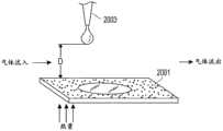
在一些实施例中,一种用于在医疗回路中使用的部件包括总体上水平的平坦微结构化表面,该微结构化表面被配置成分散置于其上的液体。该微结构化表面可以被置于流动气体路径中,并且液体分配器可以被配置成将该液体分配到该微结构化表面上。In some embodiments, a component for use in a medical circuit includes a generally horizontal flat microstructured surface configured to disperse a liquid disposed thereon. The microstructured surface can be placed in the flow gas path, and the liquid dispenser can be configured to dispense the liquid onto the microstructured surface.
在不同的实施例中,该微结构化表面包括表面不规则物。In various embodiments, the microstructured surface includes surface irregularities.
在不同的实施例中,这些表面不规则物包括下组的至少一种,该组由以下各项组成:颗粒、脊、凹槽、通道、和微粒。In various embodiments, the surface irregularities include at least one of the group consisting of particles, ridges, grooves, channels, and particles.
在不同的实施例中,该液体分配器包括至少一个滴管,该滴管被配置成将该液体一次一滴地分配到该微结构化表面上。In various embodiments, the liquid dispenser includes at least one dropper configured to dispense the liquid onto the microstructured surface one drop at a time.
在不同的实施例中,该液体分配器包括以一定距离定位于该微结构化表面上方的实质上平坦的板,该板包括多个孔洞,该液体通过这些孔洞能够落到下方的微结构化表面上。In various embodiments, the liquid dispenser includes a substantially flat plate positioned at a distance above the microstructured surface, the plate including a plurality of holes through which the liquid can fall to the underlying microstructured on the surface.
在至少一个实施例中,用于与医疗回路一起使用的部件包括总体上水平的平坦微结构化表面,该微结构化表面被配置成分散置于其上的液体,其中该微结构化表面被置于流体气体路径中;和液体分配器,该液体分配器被配置成将该液体分配到该微结构化表面上。In at least one embodiment, a component for use with a medical circuit includes a generally horizontal flat microstructured surface configured to disperse a liquid disposed thereon, wherein the microstructured surface is placed in a fluid gas path; and a liquid dispenser configured to dispense the liquid onto the microstructured surface.
在不同的实施例中,该前述部件具有以下特性中的一者、一些、或全部,以及在本披露中的其他地方所描述的特性。In various embodiments, the aforementioned components have one, some, or all of the following characteristics, as well as those described elsewhere in this disclosure.
该微结构化表面可以包括表面不规则物。这些表面不规则物可以包括下组的至少一种,该组由以下各项组成:颗粒、脊、凹槽、通道、和微粒。该液体分配器可以包括至少一个滴管,该滴管被配置成将该液体一次一滴地分配到该微结构化表面上。该液体分配器可以包括以一定距离定位于该微结构化表面上方的基本上平坦的板,该板包括多个孔洞,该液体通过这些孔洞能够落到下方的微结构化表面上。The microstructured surface may include surface irregularities. The surface irregularities may include at least one of the group consisting of particles, ridges, grooves, channels, and particles. The liquid dispenser may include at least one dropper configured to dispense the liquid onto the microstructured surface one drop at a time. The liquid dispenser may include a substantially flat plate positioned at a distance above the microstructured surface, the plate including a plurality of holes through which the liquid can fall onto the underlying microstructured surface.
在至少一个实施例中,一种适用于与加湿器一起使用的加湿腔室包括外壁,该外壁界定内部空间;和至少一个内部导壁,该内部导壁在该内部空间内并且被配置成引导气体在该加湿腔室内的流动。In at least one embodiment, a humidification chamber suitable for use with a humidifier includes an outer wall defining an interior space; and at least one interior guide wall within the interior space and configured to guide The flow of gas within the humidification chamber.
在不同的实施例中,该前述加湿腔室具有以下特性中的一者、一些、或全部,以及在本披露中的其他地方所描述的特性。In various embodiments, the aforementioned humidification chamber has one, some, or all of the following characteristics, as well as those described elsewhere in this disclosure.
该至少一个内部导壁可以包括多个导壁。该多个导壁可以被同心地安排。流动通道可以被界定在该多个导壁中的相邻者之间。该多个导壁可以界定多个流动通道,其中这些流动通道中的至少一些的大小相对于彼此变化。该导壁或这些导壁可以是总体上U型并且在该加湿腔室的入口端口与出口端口之间延伸。微结构化表面可以形成该导壁或这些导壁的至少一部分。该导壁或这些导壁可以被附接到该加湿腔室的顶壁上。The at least one inner guide wall may comprise a plurality of guide walls. The plurality of guide walls may be arranged concentrically. A flow channel may be defined between adjacent ones of the plurality of guide walls. The plurality of guide walls may define a plurality of flow channels, wherein at least some of the flow channels vary in size relative to each other. The guide wall or walls may be generally U-shaped and extend between the inlet port and the outlet port of the humidification chamber. The microstructured surface may form the guide wall or at least a portion of the guide walls. The guide wall or the guide walls may be attached to the top wall of the humidification chamber.
该加湿腔室可以进一步包括在该加湿腔室内的混合元件,该混合元件促进气相水和液相水的混合。The humidification chamber may further include a mixing element within the humidification chamber that promotes mixing of the water in the vapor phase and the water in the liquid phase.
在至少一个实施例中,一种适用于与加湿器一起使用的加湿腔室包括外壁,该外壁界定内部空间;和在该加湿腔室内的混合元件,该混合元件促进气相水和液相水的混合。In at least one embodiment, a humidification chamber suitable for use with a humidifier includes an outer wall defining an interior space; and a mixing element within the humidification chamber that promotes the mixing of water in a vapor phase and water in a liquid phase mix.
在不同的实施例中,该前述加湿腔室可以具有以下特性中的一者、一些、或全部,以及在本披露中的其他地方所描述的特性。该混合元件响应于气体流过该加湿腔室可以是可移动的。该混合元件可以是包括多个叶片的涡轮机。In various embodiments, the aforementioned humidification chamber may have one, some, or all of the following characteristics, as well as those described elsewhere in this disclosure. The mixing element may be movable in response to gas flow through the humidification chamber. The mixing element may be a turbine comprising a plurality of blades.
该加湿腔室可以进一步包括复式阀门安排,该复式阀门安排控制水通过入水口进入该加湿腔室中,其中这些阀门中的至少一者不被浮子控制。第一阀门可以被浮子控制,而第二阀门可以被包括水位传感器和阀门致动器的致动器安排控制。该第二阀门可以通常被偏置到闭合位置并且可以由该阀门致动器移动到开放位置。The humidification chamber may further comprise a double valve arrangement that controls the entry of water into the humidification chamber through the water inlet, wherein at least one of the valves is not controlled by the float. The first valve may be controlled by a float, while the second valve may be controlled by an actuator arrangement including a water level sensor and a valve actuator. The second valve can be normally biased to a closed position and can be moved to an open position by the valve actuator.
该加湿腔室可以包括平坦壁,并且该水位传感器可以位于该平坦壁上。该入口端口和该出口端口可以位于该平坦壁附近。The humidification chamber may include a flat wall, and the water level sensor may be located on the flat wall. The inlet port and the outlet port may be located near the flat wall.
该涡轮机的底面可以包括界定旋转轴的突部。该涡轮机可以包括底座,并且该多个叶片可以是可连接到该底座上的。这些叶片可以是总体上或实质上平坦的。The bottom surface of the turbine may include protrusions that define the axis of rotation. The turbine may include a base, and the plurality of blades may be attachable to the base. The vanes may be generally or substantially flat.
在至少一个实施例中,一种适用于与加湿器一起使用的加湿腔室包括外壁,该外壁界定内部空间;入水口,该入水口允许水进入该内部空间;主阀,该主阀控制水通过该入水口进入该加湿腔室中,其中该主阀是被浮子控制;以及次级阀,该次级阀控制水通过该入水口进入该加湿腔室中,其中该次级阀不被浮子控制。In at least one embodiment, a humidification chamber suitable for use with a humidifier includes an outer wall that defines an interior space; a water inlet that allows water to enter the interior space; and a main valve that controls the water into the humidification chamber through the water inlet, wherein the main valve is controlled by the float; and a secondary valve, which controls the entry of water into the humidification chamber through the water inlet, wherein the secondary valve is not controlled by the float control.
在不同的实施例中,该前述加湿腔室具有以下特性中的一者、一些、或全部,以及在本披露中的其他地方所描述的特性。该次级阀可以被包括水位传感器和阀门致动器的致动器安排控制。该第二阀门可以通常被偏置到闭合位置并且可以由该阀门致动器移动到开放位置。该第二阀门可以包括具有整体弹簧臂的阀体组件,这些整体弹簧臂通常将该阀体组件偏置到该第二阀门的闭合位置。该加湿腔室可以包括平坦壁,并且该水位传感器可以位于该平坦壁上。该入口端口和该出口端口可以位于该平坦壁附近。In various embodiments, the aforementioned humidification chamber has one, some, or all of the following characteristics, as well as those described elsewhere in this disclosure. The secondary valve may be controlled by an actuator arrangement including a water level sensor and a valve actuator. The second valve can be normally biased to a closed position and can be moved to an open position by the valve actuator. The second valve may include a valve body assembly having integral spring arms that generally bias the valve body assembly to the closed position of the second valve. The humidification chamber may include a flat wall, and the water level sensor may be located on the flat wall. The inlet port and the outlet port may be located near the flat wall.
下面更加详细地描述这些和其他实施例。These and other embodiments are described in greater detail below.
附图说明Description of drawings
现在将参见附图描述实施所披露的系统和方法的不同特征的示例实施例。附图和相关联的描述被提供为用于展示实施例,而不限制本披露的范围。Example embodiments implementing various features of the disclosed systems and methods will now be described with reference to the drawings. The drawings and associated description are provided to illustrate the embodiments, and not to limit the scope of the present disclosure.
图1示出了结合一个或多个医用管、加湿腔室以及患者接口的医疗回路的示意图。Figure 1 shows a schematic diagram of a medical circuit incorporating one or more medical tubing, a humidification chamber, and a patient interface.
图2示出了示例管的平面图。Figure 2 shows a plan view of an example tube.
图3A和3B示出了根据至少一个实施例的示例管的内部部件的第一和第二放大的纵截面。3A and 3B illustrate first and second enlarged longitudinal sections of an inner component of an example tube in accordance with at least one embodiment.
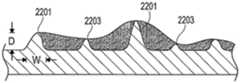
图4示出了示例微结构的横截面。Figure 4 shows a cross-section of an example microstructure.
图5A示出了管的内部部件的前透视图。Figure 5A shows a front perspective view of the internal components of the tube.
图5B示出了图5A的示出为前透视图的内部部件的第一放大部分。Figure 5B shows a first enlarged portion of the interior component of Figure 5A shown in a front perspective view.
图6示出了管内的空气流速率和温度曲线的示意图。Figure 6 shows a schematic diagram of the air flow rate and temperature profile within the tube.
图7示出了示例加湿腔室的透视图。7 shows a perspective view of an example humidification chamber.
图8A示出了包括第一微结构配置的示例加湿腔室的透视图。8A shows a perspective view of an example humidification chamber including a first microstructure configuration.
图8B和8C示出了图8A中的微结构的第一和第二放大部分的前平面图。Figures 8B and 8C show front plan views of first and second enlarged portions of the microstructure of Figure 8A.
图8D示出了示例微结构的横截面。Figure 8D shows a cross-section of an example microstructure.
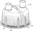
图9A示出了包括第二微结构配置的示例加湿腔室的透视图。9A shows a perspective view of an example humidification chamber including a second microstructure configuration.
图9B和9C示出了图9A中的微结构的第一和第二放大部分的前平面图。Figures 9B and 9C show front plan views of first and second enlarged portions of the microstructure of Figure 9A.
图9D示出了示例微结构的横截面。Figure 9D shows a cross-section of an example microstructure.
图10A示出了示例患者接口的前透视图。10A shows a front perspective view of an example patient interface.
图10B示出了结合传导性细丝的示例患者接口的前平面图。10B shows a front plan view of an example patient interface incorporating conductive filaments.
图11A示出了包括微结构的示例患者接口的后平面图。11A shows a rear plan view of an example patient interface including microstructures.
图11B示出了图11A中的微结构的放大部分的透视图。Figure 11B shows a perspective view of an enlarged portion of the microstructure in Figure 11A.
图11C示出了示例微结构的横截面。Figure 11C shows a cross-section of an example microstructure.
图11D示出了包括微结构的示例患者接口的后平面图。Figure 1 ID shows a rear plan view of an example patient interface including microstructures.
图12A示出了在未结合微结构的接口表面上的水滴形成的示意图。FIG. 12A shows a schematic diagram of water droplet formation on an interface surface that does not incorporate microstructures.
图12B示出了在结合微结构的接口表面上的水铺展的示意图。Figure 12B shows a schematic diagram of water spreading on the interface surface incorporating microstructures.
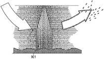
图13示意性地展示了添加的热对来自微结构的蒸发的作用。Figure 13 shows schematically the effect of added heat on evaporation from microstructures.
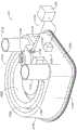
图14是医用管的制造方法的示意图,该医用管包括进料斗、朝向模头的螺旋进料机并且以波纹板轧机终止。Figure 14 is a schematic diagram of a method of manufacturing a medical tube comprising a feed hopper, a screw feeder towards a die and terminating in a corrugator.
图15是医用管件的螺旋成形制造方法的示意图。Figure 15 is a schematic diagram of a spiral forming manufacturing method for medical tubing.
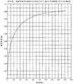
图16是用于在连续微通道中芯吸的示例条件的曲线图。Figure 16 is a graph of example conditions for wicking in continuous microchannels.
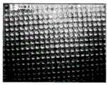
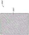
图17示出了连续微结构的图像。Figure 17 shows an image of a continuous microstructure.
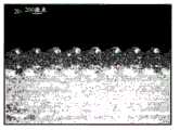
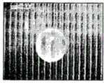
图18A到18L示出了连续的和离散的微结构的图像。18A to 18L show images of continuous and discrete microstructures.
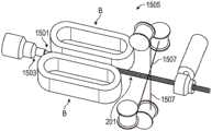
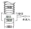
图19A展示了具有结合微结构的入口管的加湿腔室的透视图;图19B展示了用于与该入口管一起使用的预加湿轴环的侧视平面图。Figure 19A shows a perspective view of a humidification chamber with an inlet tube incorporating microstructures; Figure 19B shows a side plan view of a pre-humidification collar for use with the inlet tube.
图20展示了其中粗糙表面可以用来增强蒸发的实施例。Figure 20 illustrates an embodiment in which a rough surface can be used to enhance evaporation.
图21展示了其中粗糙表面可以用来增强蒸发的另一个实施例。Figure 21 illustrates another embodiment in which a rough surface can be used to enhance evaporation.
图22展示了表面上的一些微结构的不规则物。Figure 22 shows some of the microstructure irregularities on the surface.
图23展示了包括蒸发叠片或蒸发塔的加湿腔室的实施例。Figure 23 illustrates an embodiment of a humidification chamber including an evaporation stack or evaporation tower.
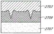
图24A展示了包括倒置梯形微结构的表面。Figure 24A shows a surface comprising inverted trapezoidal microstructures.
图24B是倒置梯形微结构中的毛细管填充长度与毛细管填充时间之间的关系的图形表示。Figure 24B is a graphical representation of the relationship between capillary fill length and capillary fill time in an inverted trapezoidal microstructure.
图25A展示了适用于在用于在平坦表面上形成微结构的方法中使用的装置。Figure 25A illustrates an apparatus suitable for use in a method for forming microstructures on a flat surface.
图25B和25C示出了适用于在图25A的装置中使用的切割刀片。Figures 25B and 25C illustrate a cutting blade suitable for use in the device of Figure 25A.
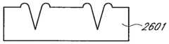
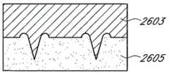
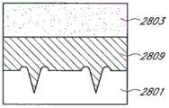
图26A到26H展示了用于在平坦表面上形成微结构的方法。26A-26H illustrate a method for forming microstructures on a flat surface.
图27A到27F展示了用于在平坦表面上形成微结构的另一种方法。Figures 27A-27F illustrate another method for forming microstructures on flat surfaces.
图28A到28D展示了用于在平坦表面上形成微结构的另一种方法。Figures 28A-28D illustrate another method for forming microstructures on flat surfaces.
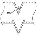
图29A到29C展示了倒置梯形微结构。Figures 29A to 29C illustrate inverted trapezoidal microstructures.
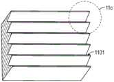
图30A展示了微结构化薄板的示意图。Figure 30A shows a schematic diagram of a microstructured sheet.
图30B展示了用于在包括图30A的微结构化薄板的加湿腔室中使用的插入物的示意图。Figure 30B shows a schematic diagram of an insert for use in a humidification chamber including the microstructured sheet of Figure 30A.
图31展示了包括引导气体流过该加湿腔室的引导特征的加湿腔室。Figure 31 illustrates a humidification chamber including directing features to direct gas flow through the humidification chamber.
图32是图31的加湿腔室的部分截面图,该部分截面图展示了这些引导特征、复式阀门安排以及用于该复式阀门安排的次级阀的致动器。32 is a partial cross-sectional view of the humidification chamber of FIG. 31 illustrating the guide features, the dual valve arrangement, and the actuator for the secondary valve of the dual valve arrangement.
图33是图31的加湿腔室的复式阀门安排的截面图。33 is a cross-sectional view of the duplex valve arrangement of the humidification chamber of FIG. 31 .
图34是包括涡轮机形式的混合元件的加湿腔室的示意俯视图。Figure 34 is a schematic top view of a humidification chamber including a mixing element in the form of a turbine.
图35是图34的与该加湿腔室分离的涡轮机的透视图。Figure 35 is a perspective view of the turbine of Figure 34 separated from the humidification chamber.
图36是图34的涡轮机的侧视图,该侧视图展示了该涡轮机的底面上的摩擦力减小特征。36 is a side view of the turbine of FIG. 34 illustrating the friction reducing features on the bottom surface of the turbine.
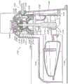
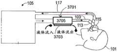
图37A示出了结合一个或多个医用管、加湿器管以及患者接口的医疗回路的示意图。图37B和37C示出了示例加湿器管的侧视平面图和前平面图。37A shows a schematic diagram of a medical circuit incorporating one or more medical tubing, a humidifier tubing, and a patient interface. 37B and 37C show side and front plan views of an example humidifier tube.
贯穿这些附图,参见号被频繁再使用以指示所参见的(或类似的)元件之间的对应。此外,每一参见号的第一个数字(或第一组数字)指示该元件第一次出现在其中的附图。Throughout the drawings, reference numerals are frequently reused to indicate correspondence between referenced (or analogous) elements. Additionally, the first digit (or first set of digits) of each reference number identifies the drawing in which the element first appears.
具体实施方式Detailed ways
以下详细说明披露了新的医疗回路部件和形成这些部件的方法,这些部件例如吹气、麻醉、或呼吸回路部件。如上文所解释,这些部件包括用于加湿和/或冷凝物管理的微结构。这些披露的微结构可以结合在许多种部件中,包括管(例如,吸气性呼吸管和呼气性呼吸管以及在一种呼吸回路的不同元件之间的其他管件,这些元件例如通气机、加湿器、过滤器、聚水器、样品管线、连接器、气体分析器,等等)、Y型连接器、导管接合器、加湿器、以及患者接口(例如,用于覆盖鼻子和脸的遮罩、鼻罩、套管、鼻枕,等等)、浮子、探头、以及在许多种医疗回路中的传感器。医疗回路是广义术语,并且对本领域的普通技术人员给出了它的通常并且惯常的含义(也就是说,它不限于特殊或自定义的含义)。因此,医疗回路意味着包括开放回路,例如某些CPAP系统,这些开放回路可以包括在通气机/送风机与患者接口之间的单个吸气性呼吸管;还包括闭合回路。The following detailed description discloses new medical circuit components, such as insufflation, anesthesia, or breathing circuit components, and methods of forming such components. As explained above, these components include microstructures for humidification and/or condensate management. The disclosed microstructures can be incorporated into a wide variety of components, including tubing (eg, inspiratory and expiratory breathing tubes and other tubing between different elements of a breathing circuit, such as ventilators, Humidifiers, filters, water traps, sample lines, connectors, gas analyzers, etc.), Y-connectors, conduit adapters, humidifiers, and patient interfaces (e.g., masks for nose and face masks, nasal masks, cannulas, nasal pillows, etc.), floats, probes, and sensors in many types of medical circuits. Medical circuit is a broad term and is given its ordinary and customary meaning to those of ordinary skill in the art (that is, it is not limited to a special or custom meaning). Thus, a medical circuit is meant to include open circuits, such as certain CPAP systems, which may include a single inspiratory breathing tube between the ventilator/blower and the patient interface; and also closed circuits.
下文参见附图描述了关于用于实施在此描述的装置和方法的若干说明性实施例的细节。本发明不限于这些描述的实施例。Details regarding several illustrative embodiments for implementing the apparatus and methods described herein are described below with reference to the accompanying drawings. The invention is not limited to these described embodiments.
医疗回路medical circuit
为了更详细地理解本披露,首先参见图1,图1示出了根据至少一个实施例的医疗回路。更具体地,图1示出了示例呼吸回路。该呼吸回路可以是,例如,连续、可变或双水平的气道正压(PAP)系统或另一种形式的呼吸疗法。如下文解释,该呼吸回路包括一个或多个医用管、加湿器以及患者接口。该医疗回路的任何或全部这些部件以及其他部件可以结合用于加湿和/或冷凝物管理的微结构。微结构通常可以被定义为具有在1到1000微米(μm)(或约1到1000μm)范围中的微尺度大小的结构。For a more detailed understanding of the present disclosure, reference is first made to FIG. 1, which illustrates a medical circuit in accordance with at least one embodiment. More specifically, FIG. 1 shows an example breathing circuit. The breathing circuit may be, for example, a continuous, variable or bi-level positive airway pressure (PAP) system or another form of breathing therapy. As explained below, the breathing circuit includes one or more medical tubing, a humidifier, and a patient interface. Any or all of these and other components of the medical circuit may incorporate microstructures for humidification and/or condensate management. Microstructures can generally be defined as structures having a microscale size in the range of 1 to 1000 micrometers (μm) (or about 1 to 1000 μm).
可以如下在图1的回路中运送气体。干燥气体从通气机/送风机105传递到加湿器107,该加湿器对这些干燥气体进行加湿。在某些实施例中,该通气机/送风机105可以与该加湿器107整合。该加湿器107经由出口端口111连接到吸气管103的入口109(用于接收加湿气体的末端)上,由此将加湿气体供应给该吸气管103。吸气管是被配置成向患者输送呼吸气体的管。这些气体通过该吸气管103流动到出口113(用于排出加湿气体的末端),并且随后通过被连接到该出口113上的患者接口115流动到患者101。在这个实例中,该出口113是Y型件适配器。呼气管117也连接到该出口113上。呼气管是被配置成使呼出的加湿气体移动远离患者的管。此处,该呼气管117使呼出的加湿气体从该患者接口115返回到该通气机/送风机105。根据至少一种配置的吸气管103和/或呼气管117可以包括微结构。下文更详细地描述这些管(和其他管)。Gas may be transported in the circuit of Figure 1 as follows. The dry gas is passed from the ventilator/
在这个实例中,干燥气体通过通气口119进入该通气机/送风机105中。风扇121可以凭借抽吸空气或其他气体通过该通气口119来改进进入该通气机/送风机105中的气流。例如,该风扇121可以是变速风扇,其中电子控制器123控制该风扇速度。具体是,该电子控制器123的功能可以被电子主控制器125响应于来自该主控制器125的输入和/或由用户经由拨盘127设置的压力或风扇速度的设置值来控制。In this example, drying gas enters the ventilator/
该加湿器107包括加湿腔室129,该加湿腔室129含有一定体积的水130或其他适合的加湿液体。优选地,该加湿腔室129在使用之后是从该加湿器107上可移除的。可移除性允许该加湿腔室129更容易被消毒或处置。然而,该加湿器107的腔室129部分可以是整体构造。该加湿腔室129的主体可以由非传导性玻璃或塑料材料形成。但是该加湿腔室129也可以包括传导性部件。例如,该加湿腔室129可以包括高导热性的底座(例如,铝底座),该底座与该加湿器107上的加热器板131接触或相关联。举例来说,该加湿器107可以是独立加湿器,例如在新西兰奥克兰市的斐雪派克(Fisher&Paykel)医疗保健有限公司的呼吸加湿范围中的加湿器中的任一者。示例加湿腔室129被描述于授予西姆斯(Sims)的美国专利号5,445,143中,该专利通过引用将其全文结合。The
根据至少一个实施例的加湿腔室129可以包括微结构并且在此对该加湿腔室129进行进一步详细描述。The
该加湿器107还可以包括电子控制件。在这个实例中,该加湿器107包括该电子主控制器125。优选地,该电子主控制器125是基于微处理器的控制器,该控制器执行存储在相关联的存储器中的计算机软件命令。响应于由用户经由(例如)用户接口133设置的湿度或温度值输入以及其他输入,该电子主控制器125确定何时(或以何种水平)对该加热器板131进行供能,以便对该加湿腔室129内的水130进行加热。The
可以结合任何适合的患者接口115。患者接口是广义术语,并且对本领域的普通技术人员给出了它的普遍并且惯常的含义(也就是说,它不限于特殊或自定义的含义),并且包括而不限于遮罩(例如气管罩、面罩以及鼻罩)、套管以及鼻枕。温度探头135可以连接到靠近该患者接口115的吸气管103上,或连接到该患者接口115上。该温度探头135监测该患者接口115附近或在该患者接口115处的温度。与该温度探头相关联的加热细丝(未示出)可以用于调整该患者接口115和/或吸气管103的温度,以便将该吸气管103和/或患者接口115的温度升高到饱和温度之上,由此减少不想要的冷凝的机会。Any
根据至少一个实施例的患者接口115可以包括微结构并且在下文对该患者接口115进行更详细的描述。The
在图1中,呼出的加湿气体经由该呼气管117从该患者接口115返回到该通气机/送风机105。该呼气管117可以具有与它整合的温度探头和/或加热细丝(如上文关于该吸气管103所描述),从而减少冷凝的机会。此外,该呼气管117不需要使呼出气体返回到该通气机/送风机105。可替代地,呼出的加湿气体可以直接被传递到周围环境或被传递到其他辅助装置,例如空气洗涤器/过滤器(未示出)。在某些实施例中,完全省略了该呼气管。In FIG. 1 , exhaled humidified gas is returned from the
如上文讨论,该示例医疗回路的吸气管103、呼气管117、加湿腔室129、和/或患者接口115可以包括微结构。这些部件讨论如下。本发明并不被这些实施例所限制,然而,可以预见的是,这些披露的微结构可以被整合到接触和/或运送加湿气体(例如加湿空气)的许多种医疗部件中。As discussed above, the
具有微结构的医用管Medical tube with microstructure
图2示出了根据至少一个实施例适合用于在医疗回路中使用的管201的透视图。如图2中示出,该管201可以是波纹状的,这有利地改进了该管的柔性。然而,在某些实施例中,该管201可以具有相对光滑的非波纹壁。Figure 2 shows a perspective view of a
在某些实施例中,该管201可以用于运送气体到婴儿或新生儿患者和/或用于输送来自婴儿或新生儿患者的气体。在某些实施例中,该管201可以用于运送气体到标准患者(例如较大的儿童和成人)和/或用于运送来自这些标准患者的气体。在此描述的“婴儿”和“标准”医用管的一些示例尺寸、以及这些尺寸的一些优选范围被描述于共同拥有的2011年6月3日提交的美国临时专利申请号61/492,970和2012年3月13日提交的美国临时专利申请号61/610,109中,以及共同拥有的国际公开号WO 2011/077250 A1中,这些文献中的每一者通过引用将其全文结合。用于婴儿和标准管的示例长度可以是1到2m(或约1到2m)。In certain embodiments, the
在至少一个实施例中,该管201由包括一种或多种聚合物的挤出物形成。优选地,该聚合物被选择为使得形成的管201是总体上柔性的。优选的聚合物包括线性低密度聚乙烯(LLDPE)、低密度聚乙烯(LDPE)、聚丙烯(PP)、聚烯烃塑性体(POP)、乙烯乙酸乙烯酯(EVA)、增塑聚氯乙烯(PVC)、或这些材料中的两者或更多者的共混物。该聚合物(这些聚合物)形成总挤出物的至少98.4(或约98.4)、98.5(或约98.5)、98.6(或约98.6)、98.7(或约98.7)、98.8(或约98.8)、98.9(或约98.9)、99.0(或约99.0)、99.1(或约99.1)、99.2(或约99.2)、99.3(或约99.3)、99.4(或约99.4)、99.5(或约99.5)、99.6(或约99.6)、99.7(或约99.7)、99.8(或约99.8)、或99.9(或约99.9)的重量百分比(wt.%)。在具体实施例中,该挤出物包括99.488(或约99.488)wt.%或约99.49(或约99.49)wt.%的LLDPE。在某些实施例中,该管201由被描述于共同转让的国际公开号WO 2001/077250 A1中的发泡聚合物形成,该文献通过引用将其全文结合。In at least one embodiment, the
在一些实施例中,微结构可以由软金属材料(例如铝箔、黄铜、以及铜)形成。在一些这样的实施例中,选择的这些材料可以具有高表面能。在一些实施例中,这些基底材料可以被涂覆并且可以包括增加该基底材料的表面能的添加剂。在一些实施例中,未形成在微结构中的单独的金属的使用可能是有利的,原因仅仅在于高表面能。但是微结构可由这些金属形成,例如通过首先将该软金属形成膜或薄膜并且随后冲压该材料以形成微结构。随后该冲压材料可以用来形成本披露的这些加湿装置中的任何数量的适合部件。例如,该管201的至少一内部部分可以由金属形成,该金属可能已经或可能尚未被冲压形成微结构。并且在一些实施例中,冲压的金属膜可以形成在加湿腔室内的任何数量的结构(壁、塔、鳍片、底座,等等)上的表面。In some embodiments, the microstructures may be formed from soft metallic materials such as aluminum foil, brass, and copper. In some such embodiments, these materials are selected to have high surface energies. In some embodiments, the base materials can be coated and can include additives that increase the surface energy of the base materials. In some embodiments, the use of a separate metal that is not formed in the microstructure may be advantageous simply because of the high surface energy. But microstructures can be formed from these metals, for example by first forming the soft metal into a film or thin film and then punching the material to form the microstructures. The stamped material can then be used to form any number of suitable components in the humidification devices of the present disclosure. For example, at least an interior portion of the
在某些实施例中,该管201可以包括一根或多根传导性细丝。在某些实施例中,该管201可以包括两根或四根传导性细丝,并且成对的这些传导性细丝可以在该管201的一端或两端形成连接环。该一根或多根细丝可以被布置在该管201的外部上,例如,围绕该管201的外部螺旋缠绕,或者布置在该管201的内壁上,例如沿着内腔壁周围螺旋缠绕。下文更详细地论述细丝。In certain embodiments, the
已发现在液体与包括为特定目的建造的微结构的表面之间的相互作用可以导致该液体铺展到该表面上和这些微结构的内部或其上。进一步发现这种相互作用增加了液体-蒸气界面面积并且降低了在该表面顶部上的液体层的厚度。相比于在平坦表面上的相同体积的液体,增加的表面面积与降低的厚度的组合改进了液体的蒸发。如下文讨论,增加的表面面积、降低的厚度、以及加热的组合进一步改进了液体的蒸发。因此,在不同的实施例中,该管201的这些内壁包括微结构301,如在图3A(未按比例)中示出。图3B中示出了这些微结构301的一部分的第一放大视图。图3B以大于图3A的放大率示出了这些微结构301。在图3A和3B中,这些微结构301沿着该管201轴向布置(也就是说,这些微结构以垂直于该管201的纵向长度的方向延伸)。It has been found that interactions between a liquid and a surface comprising purpose-built microstructures can cause the liquid to spread onto the surface and in or on the microstructures. This interaction was further found to increase the liquid-vapor interfacial area and reduce the thickness of the liquid layer on top of the surface. The combination of increased surface area and reduced thickness improves evaporation of the liquid compared to the same volume of liquid on a flat surface. As discussed below, the combination of increased surface area, reduced thickness, and heating further improves liquid evaporation. Thus, in various embodiments, the inner walls of the
聚合物通常具有低表面能,导致可湿性不良。为了改进这些微结构301在聚合物管201上的水铺展能力,可有利的是用一种或多种材料处理该一种或多种聚合物,以便增加该表面能。表面活性剂(例如阳离子表面活性剂)可以是特别令人希望的添加剂材料。适合的表面改性剂包括单硬脂酸甘油酯(GMS)、乙氧基化胺、烷基磺酸钠盐、和月桂酸二乙醇酰胺以及包含这些物质的添加剂。由科莱恩(Clariant)(新西兰)有限公司供应的并且产品名称为“418LD抗静电母料”的MLDNA-418是表面改性剂母料,其中5(±0.25)%的单硬脂酸甘油酯(CAS号123-94-4)作为活性成分。优选地,该表面改性剂包括该总挤出物的至少约0.05(或约0.05)、0.1(或约0.1)、0.15(或约0.15)、0.2(或约0.2)、0.25(或约0.25)、0.3(或约0.3)、0.35(或约0.35)、0.4(或约0.4)、0.45(或约0.45)、0.5(或约0.5)、1.1(或约1.1)、1.2(或约1.2)、1.3(或约1.3)、1.4(或约1.4)、或1.5(或约1.5)wt.%。例如,在至少一个实施例中,该管挤出物包括0.25wt.%(或约0.25wt.%)的表面改性剂。作为另一个实例,在至少一个实施例中,该管挤出物包括0.5wt.%(或约0.5wt.%)的表面改性剂。Polymers generally have low surface energies, resulting in poor wettability. In order to improve the water spreading ability of the
其他材料(例如其他表面活性剂或其他亲水剂)也可以用来改进该管201或其他实施例的水铺展能力。例如,可以使用任何适合的阴离子、阳离子或非离子表面活性剂或其他亲水剂,或这些表面活性剂或亲水剂的组合。适合的亲水剂可以是通常能够增加组合物的亲水特性的任何一种试剂或多种试剂。在一些配置中,该表面活性剂或亲水剂可以包括乙氧基化脂肪醇,例如被描述于EP 0 480 238 B1中的乙氧基化脂肪醇,该文献通过引用将其全文结合在此。在一些配置中,该表面活性剂或亲水剂可以包括非离子表面活性物质,例如壬基酚乙氧基化合物、聚乙二醇单酯和双酯、脱水山梨糖醇酯、聚乙二醇单醚和二醚以及被描述于EP 0 268 347 B1中的其他物质,或非离子全氟烷基化表面活性物质,例如被描述于WO 87/03001中的表面活性物质,这些文献通过引用将其全文结合在此。在一些配置中,该表面活性剂或亲水剂可以含有硅部分。在一些配置中,该表面活性剂或亲水剂可以包括湿润剂,例如被描述于如以上提及的WO 87/03001和EP 0 231 420 B1中的亲水硅油,这些文献通过引用将其全文结合在此。在一些配置中,该表面活性剂或亲水剂可以包括聚醚碳硅烷,例如被描述于WO 2007/001869中尤其是在第13页和14页的聚醚碳硅烷,该文献通过引用将其全文结合在此。其他这些适合的试剂被描述于US 5,750,589、US 4,657,959以及EP0 231 420 B1中,如在WO 2007/001869中引用的,这些文献通过引用将其全文结合在此。在一些配置中,该表面活性剂或亲水剂可以包括含有硅氧烷增溶基团的乙氧基化表面活性剂,例如被描述于以上提及的US 4,657,949和WO 2007/001869中的表面活性剂。这些乙氧基化表面活性剂的实例是可从美国纽约州奥尔巴尼(Albany)迈图高新材料集团(Momentive Performance Materials)获得的表面活性共聚物的


在某些实施例中,一种或多种亲水剂在形成这些微结构之后被施加到微结构化表面。例如,该微结构化表面可以被浸没在挥发性溶剂(例如,甲醇或乙醇)中的

也可以使用其他方法来增加表面能。适合的方法包括物理、化学、以及辐射方法。物理方法包括,例如,物理吸附和朗缪尔-布洛杰特膜(Langmuir-Blodgett film)。化学方法包括通过强酸、臭氧处理、化学吸附、以及火焰处理进行氧化。辐射方法包括等离子体(辉光放电)、电晕放电、光活化(UV)、激光、离子束、电子束、以及伽马辐照。Other methods can also be used to increase the surface energy. Suitable methods include physical, chemical, and radiation methods. Physical methods include, for example, physical adsorption and Langmuir-Blodgett films. Chemical methods include oxidation by strong acid, ozone treatment, chemisorption, and flame treatment. Irradiation methods include plasma (glow discharge), corona discharge, photoactivation (UV), laser, ion beam, electron beam, and gamma irradiation.
通过选择适合的表面改性方法或表面改性剂,可提供管壁,该管壁具有小于50(或约50)、45(或约45)、40(或约40)、35(或约35)、30(或约30)、25(或约25)、20(或约20)度(°)的表面特性接触角,如是可通过角度测量装置(例如测角计)测量的。例如,具有小于35°(或约35°)的表面特性接触角的管壁提供有用的结果。令人希望地,该接触角小于π/2(或约π/2)。更令人希望地,该接触角为0°或约0°。By selecting a suitable surface modification method or surface modifier, a tube wall can be provided having less than 50 (or about 50), 45 (or about 45), 40 (or about 40), 35 (or about 35 ), 30 (or about 30), 25 (or about 25), 20 (or about 20) degrees (°), as can be measured by an angle measuring device such as a goniometer. For example, pipe walls with surface characteristic contact angles of less than 35° (or about 35°) provide useful results. Desirably, the contact angle is less than π/2 (or about π/2). More desirably, the contact angle is at or about 0°.
下方的表1示出了对于不同的LLDPE样品的接触角测量,这些样品包括用表面改性剂处理的样品和用辐射处理的样品。这些接触角测量是基于根据ASTM标准D7334,2008,“通过推进接触角测量来进行的涂层、基底和色素的表面可湿性的标准实践(StandardPractice for Surface Wettability of Coatings,Substrates and Pigments byAdvancing Contact Angle Measurement)”进行的静态液滴形状测试方法。Table 1 below shows the contact angle measurements for different LLDPE samples, including samples treated with surface modifiers and samples treated with radiation. These contact angle measurements are based on Standard Practice for Surface Wettability of Coatings, Substrates and Pigments by Advancing Contact Angle Measurement )" static drop shape test method.
表1Table 1


与所测试的其他表面改性方法相比,具有5%MLDNA-418表面改性剂的样品产生最低的测量接触角。The sample with 5% MLDNA-418 surface modifier yielded the lowest measured contact angle compared to other surface modification methods tested.
如上文讨论,在某些实施例中,将该添加剂材料添加到本体聚合物挤出物。可令人希望的是将该材料添加到该聚合物基质中,以便针对该管的使用寿命对该表面补足该添加剂材料。在某些配置中,例如通过用该材料涂覆该聚合物的表面,可以将该材料作为表面处理添加到该聚合物上。例如,可以用添加剂材料进行刷、喷、或别的方式涂覆微结构化表面,该添加剂材料例如HYDRON抗雾涂层(宾夕凡尼亚州兰开斯特(Lancaster)MXL工业公司)、EXXENE抗雾涂层,例如HCAF-100(德克萨斯州科珀斯克里斯蒂(Corpus Christi)Exxene公司)、以及模克隆(MAKROLON)抗雾涂层(拜耳公司),从而产生薄的(例如,1μm或大约如此)添加剂材料涂层。表面涂层可以是令人希望的,原因在于低成本和易于制造。As discussed above, in certain embodiments, the additive material is added to the bulk polymer extrudate. It may be desirable to add the material to the polymer matrix to replenish the surface with the additive material for the life of the tube. In certain configurations, the material may be added to the polymer as a surface treatment, such as by coating the surface of the polymer with the material. For example, the microstructured surface may be brushed, sprayed, or otherwise coated with an additive material such as HYDRON Anti-Fog Coating (MXL Industries, Lancaster, PA), EXXENE anti-fog coatings, such as HCAF-100 (Exxene, Corpus Christi, TX), and MAKROLON anti-fog coatings (Bayer), resulting in thin (eg, 1 μm or so) additive material coating. Surface coatings can be desirable because of low cost and ease of manufacture.
在某些配置中,可以作为表面改性剂浇注亲水材料的薄膜,该亲水材料例如可呼吸聚氨酯,例如ESTANE 58245(俄亥俄州威克利夫(Wickliffe)路博润(Lubrizol)公司)、可呼吸聚酯,例如ARNITEL VT3108(荷兰锡塔德(Sittard)帝斯曼工程塑料公司(DSMEngineering Plastics))、或可呼吸聚酰胺类,例如PEBAX(法国科龙贝(Colombes)阿科玛公司(Arkema))。这些亲水材料可以吸收水分并且变得非常可湿润。实施该亲水薄膜的示例方法包括:将该可呼吸聚合物溶解在溶剂中,浇注该混合物,并且允许该溶剂蒸发,因此在这些微结构上留下该可呼吸材料的薄膜。例如,可以将ESTANE 58245小球溶解在二甲基甲酰胺(DMF)溶剂的四氢呋喃(THF)中,并且浇注到微结构上,这些微结构是使用微铣削工艺从黄铜或铝切削加工而成。该薄膜的典型尺寸是在1到10μm(或约1到10μm)的范围中。优选地,该溶剂、可呼吸材料、以及微结构材料的组合被选择为使得例如通过用该溶剂溶解这些微结构,该微结构的形状和质量实质上不被影响。In certain configurations, films of hydrophilic materials, such as breathable polyurethanes such as ESTANE 58245 (Lubrizol, Wickliffe, Ohio), may be cast as surface modifiers. Respirable polyesters such as ARNITEL VT3108 (DSM Engineering Plastics, Sittard, The Netherlands), or breathable polyamides such as PEBAX (Arkema, Colombes, France) )). These hydrophilic materials can absorb moisture and become very wettable. An example method of implementing the hydrophilic film includes dissolving the breathable polymer in a solvent, casting the mixture, and allowing the solvent to evaporate, thereby leaving a film of the breathable material on the microstructures. For example, ESTANE 58245 pellets can be dissolved in tetrahydrofuran (THF) in dimethylformamide (DMF) solvent and cast onto microstructures machined from brass or aluminum using a micromilling process . Typical dimensions of the film are in the range of 1 to 10 μm (or about 1 to 10 μm). Preferably, the combination of the solvent, breathable material, and microstructured material is selected such that the shape and quality of the microstructures are not substantially affected, eg by dissolving the microstructures with the solvent.
某些实施例包括实现图3A和3B中示出的垂直配置可有利地改进加湿和冷凝物管理。如图1中示出,管(例如,该吸气管103或呼气管117)总体上在水平方向上延伸,但是某些部分可以垂直地延伸,尤其是接近该管的末端,并且一些部分可以是倾斜的。在重力作用下,冷凝物倾向于沿着该管的垂直部分和倾斜部分向下流,并且汇集在该总体上水平的管的最低点处。当微结构垂直于该总体上水平的管的底部时,这些微结构将使汇集的冷凝物克服重力垂直移动。此作用增加了在这些管壁上的冷凝物的量,并且因此增加了被暴露于空气流的冷凝物的表面面积。将冷凝物的更大表面面积暴露于该空气流增加了该冷凝物将蒸发到该空气流中的可能性。因此,该垂直配置减少了汇集在该管中的冷凝物,并且改进了流过该管的空气保持所希望的接近饱和的湿度水平的可能性。Certain embodiments including implementing the vertical configuration shown in Figures 3A and 3B may advantageously improve humidification and condensate management. As shown in Figure 1, the tube (eg, the
这种配置可以是有利的,因为它引起最低限度的该管内腔中空气流的破坏,原因在于没有结构延伸到该内腔中。至少一个实施例包括实现微结构不必延伸到该内腔中或覆盖该内腔以便增强蒸发。This configuration can be advantageous because it causes minimal disruption of air flow in the lumen of the tube, since no structure extends into the lumen. At least one embodiment includes realizing that microstructures do not have to extend into or cover the lumen in order to enhance evaporation.
图19A展示了该加湿腔室129的实施例,结合微结构1903的管1901被附接在该加湿腔室129的入口端口701处。该管1901的另一端被连接到波纹干燥管线1909上,该波纹干燥管线1909从通气机/送风机(未示出)引出。空气通过该管1901从该通气机/送风机流动到该干燥管线1909中、流动到该入口端口901中并且随后流动到该加湿腔室129中。管1901具有非波纹壁。液体(例如水)可以被分配到该管1901中,在该入口端口701上方一定的距离,使得水在该加湿腔室129的方向流过这些微结构1903并且沿着这些微结构流动。根据一些实施例并且如图19A中示出,这些微结构1903可在该管的方向纵向地取向。这些微结构1903可替代地在沿该管壁的圆周方向取向。图19A的管1901可以有利地用来对流到该加湿腔室129中的气体进行预加湿。FIG. 19A shows an embodiment of the
在一些配置中,可以将该液体量取到该管1901的内表面上,使得受控引入围绕该圆周并且通过使用这些微结构和重力沿着该管1901的内表面铺展该液体。可以使用任何适合的限速装置(例如限流器)控制液体的引入。可以使用该限速装置调节水流入该管1901中的速率,以便将水与该管1901中的这些微结构1903之间的相互作用最大化。例如,增加该管1901中的水的量可以增加发生的蒸发量。然而,如果不被完全覆盖或涂覆在水中,那么这些微结构1903可以是最有效的。已经发现蒸发发生在主要沿着水的边缘和周围结构的粗糙表面上。因此,可能令人希望的是控制流过该管1901的水的量,从而将针对水的边缘数目最大化。In some configurations, the liquid can be metered onto the inner surface of the
图19B示出了用于将液体输送到图19A的框1910的区域中的管1901的示例装置。液体供应管(未示出)经由输入1913将液体提供到轴环1911,并且该轴环1911将液体供应到该管1901。如上文描述的任选限速装置(未示出)可以用来调节液体到轴环1911的流动。例如,在一些实施例中,该液体供应管可以在该限速装置与该轴环1911之间延伸。该轴环1911可以任选地包括在套筒1915的外表面上的微通道,这些微通道可以与该管1901上的微通道流体连通。此外,该轴环1911可以包括端口,该干燥管线1909可以连接到该端口。向下流或通过该管1901流向该加湿腔室129的空气开始蒸发并且带走来自该管1901的内表面的水。因此,到达该加湿腔室129的空气已经获得至少一些水蒸气。Figure 19B shows an example apparatus for delivering liquid to the
在一些实施例中,加热器金属丝1907可以被结合到该管1901上或该管1901中。图19A的加热器金属丝1907是以示意图表示出在该管1901的外部上(或外表面上)。可替代地(或此外),该加热器金属丝1907可以被布置在该管1901内(例如,该管内腔内或该内腔壁上)和/或被包埋在该管1901壁中。热夹套(未示出)也可以被结合到该管1901的至少一部分中,或可以围绕该至少一部分。该热夹套可以进一步增强水或液体蒸发到该流动的气体中。在一些实施例中,不同于具有热夹套或除了具有热夹套之外,该管1901可以具有印在该管1901的一个或多个部分上的加热器。在一些实施例中,该管1901可以包括例如厚膜加热元件、腐蚀箔或金属丝元件的结构,以便提供加热元件。In some embodiments, heater wire 1907 may be incorporated onto or into the
可以按任何适合的方式并且使用任何适合的材料形成具有这些微结构1903的管1901。在一些实施例中,可以从由亲水聚合物形成的波纹板形成该管1901。一旦形成,可以将该波纹材料缠绕而形成具有这些微结构1903的管1901,这些微结构1903沿着形成的结构的内表面的长度的至少一部分延伸。在一些实施例中,这些微结构1903是V型槽。在一些实施例中,这些V型槽包括沟槽,当该薄板被平坦布置时,这些沟槽与邻近沟槽距离约30μm。在一些配置中,该薄板和因此形成的管1901可以为约150mm长,并且在折叠形成该管1901之后可以具有约20mm的直径。
图37A展示了图1的消除了图1的加湿器107的系统的可替代配置。干燥气体从通气机/送风机105传递到加湿器管3701,该加湿器管3701对这些干燥气体进行加湿。该加湿器管3701连接到吸气管103上,该吸气管103经由出口113(在这个实例中,Y型件适配器)将加湿气体输送到该患者101。呼气管117也连接到该出口113上。此处,该呼气管117使呼出的加湿气体从该患者接口115返回到该通气机/送风机105。根据至少一种配置的吸气管103和/或呼气管117可以包括如本披露中描述的微结构。该加湿器管3701包括微结构化管道3705。该微结构化管道的内壁(邻近该内腔)包括如在此描述的微结构。这些微结构可被周向地布置。可替代地,这些微结构可被纵向地布置。令人希望的,该微结构化管道3705并非波纹状。然而,在某些实施例中,该微结构化管道3705可以是波纹状的。FIG. 37A illustrates an alternative configuration of the system of FIG. 1 that eliminates the
如图37B中更详细示出,液体供应管道3703可被布置在该微结构化管道3705附近。该液体供应管道3703将该加湿液体提供到该加湿器管3701。可以作为溢流系统输送流过该液体供应管道3703的液体。可替代地,可以经由再循环器输送该液体。令人希望的,使用适合的限速装置(例如限流器)控制该液体的引入。液体供应管道3703的内腔与微结构化管道3705的内腔流体连通。例如,这些内腔可以经由多个小的或毛细管大小的孔洞、经由小的或毛细管大小的通道、经由半渗透隔膜或经由例如尼龙的液体渗透材料而连通。液体管道1905的直径、这些孔洞或通道的大小、该隔膜的渗透性,和/或该材料的密度可以被选择为进一步控制液体被提供到该管1901的内表面上的速率。如图37C、图37A和37B的微结构化管道3705和液体供应管道3703的前平面图中示出,在使用时,该液体供应管道3703中的液体传递到该微结构化管道3705中。该液体被芯吸并且铺展在该微结构化管道3705的表面上方,并且流过该微结构化管道3705的空气吸收该液体,由此对该空气加湿。As shown in more detail in FIG. 37B , a
作为液体供应管道的替代,轴环可被布置在该微结构化管道3705的前进端上(也就是说,更靠近该通气机/送风机105的末端上)。该轴环可以本质上类似于图19B的上下文中描述的轴环1911。As an alternative to liquid supply conduits, a collar may be placed on the forward end of the microstructured conduit 3705 (ie, closer to the end of the ventilator/blower 105). The collar may be substantially similar to
图4展示了示例微结构301a的横截面。在这个示例实施例中,该微结构301a是具有楔状结构的连续微通道。连续微通道通常可被定义为具有1000μm(或约1000μm)或更小的尺寸的连续通道。在至少一个实施例中,该微通道具有20到40μm(或约20到40μm)的深度d、20μm(或约20μm)的最大宽度w,以及30°到60°(或约30°到60°)的角度。在某些实施例中,管表面具有1:1(或约1:1)的微通道-固体比。这些前述尺寸不是限制性的,并且下文更详细地讨论另外的适合尺寸。由于上文讨论的这些示例实施例与这些示例管尺寸之间的尺度差异,微结构化表面可以在开放系统而不是闭合系统(例如芯片实验室)中停留和运行。Figure 4 shows a cross-section of an
某些实施例包括实现液体在微通道中的移动主要是基于表面力而不是惯性力或重力。某些实施例还包括实现如果该微结构的特征尺寸小于毛细管长度(Lc),那么表面力通常占优势,该毛细管长度被定义为Certain embodiments include enabling movement of liquids in microchannels based primarily on surface forces rather than inertial or gravitational forces. Certain embodiments also include realizing that if the feature size of the microstructure is smaller than the capillary length (Lc ), the surface force generally prevails, the capillary length being defined as

其中σ代表表面张力,ρ代表流体密度,并且g代表重力加速度常数(9.8m/s2)。对于室温下的水,毛细管长度是约2.3mm。根据这些前述实现,小于约2.3mm的微尺度大小可导致对于室温下的水的可观察的表面现象。然而发现,这些微结构的大小并非总是指示是否存在可观察的毛细管芯吸、表面面积的增加、和/或膜厚度的降低。因此,在某些实施例中,这些微结构包括具有小于π/2(或约π/2)的平衡接触角的底座基底。在等温(或接近等温)条件下,并且在小于该毛细管长度的长度尺度上,可以定义取决于该微结构的高宽比和临界平衡接触角的用于芯吸的标准。对于方形槽,该关系可以被表达为where σ represents the surface tension, ρ the fluid density, and g the gravitational acceleration constant (9.8 m/s2 ). For water at room temperature, the capillary length is about 2.3 mm. According to these aforementioned implementations, microscale sizes of less than about 2.3 mm can result in observable surface phenomena for water at room temperature. It has been found, however, that the size of these microstructures is not always indicative of the presence or absence of observable capillary wicking, an increase in surface area, and/or a decrease in film thickness. Thus, in certain embodiments, these microstructures include pedestal substrates with equilibrium contact angles of less than π/2 (or about π/2). Under isothermal (or near isothermal) conditions, and on length scales smaller than the capillary length, criteria for wicking can be defined that depend on the aspect ratio and critical equilibrium contact angle of the microstructure. For square slots, the relationship can be expressed as

其中X为高宽比。对于v形凹槽,该关系可以被表达为where X is the aspect ratio. For v-grooves, the relationship can be expressed as

其中β为该凹槽楔形体的角度。图16是用于在连续微通道特别是方形凹槽(1601)和v形凹槽(1603)中芯吸的示例条件的曲线图。在曲线下方的区域中,倾向于发生芯吸到这些通道中。在这些曲线的略微上方的区域中,观察到连绵到许多介稳平衡中的液滴,但是并不倾向于发生芯吸。在这些曲线的更上方的区域中,未观察到液滴连绵,并且没有发生芯吸。表面可湿性与通道高宽比的不同组合将导致液体芯吸到这些微通道中,前提是该特征尺寸小于针对该液体的毛细管长度(使得表面张力强于粘性力)。然而,一般而言,如果条件使得θcrit在这些曲线下方,那么液体将芯吸到这些通道中。where β is the angle of the groove wedge. Figure 16 is a graph of example conditions for wicking in continuous microchannels, particularly square grooves (1601) and v-grooves (1603). In the region under the curve, wicking into these channels tends to occur. In the slightly upper region of these curves, droplets that lingered into many metastable equilibrium were observed, but did not tend to wick. In the upper regions of these curves, droplet tethering was not observed and wicking did not occur. Different combinations of surface wettability and channel aspect ratio will result in liquid wicking into these microchannels, provided that the feature size is smaller than the capillary length for the liquid (making surface tension stronger than viscous forces). In general, however, if conditions are such that the θcrit is below these curves, then liquid will wick into these channels.
根据以上实现确定,为了促进芯吸,具有高高宽比和/或高表面能(低接触角)的结构是令人希望的。例如上文讨论的表面活性剂可以导致接近0°的接触角,因此可以轻而易举地发生芯吸。在大多数聚合物表面上方的平衡接触角大于约0.87弧度(约50°),因此可以实施更深的通道来促进润湿。From the above realizations it was determined that in order to facilitate wicking, structures with high aspect ratios and/or high surface energies (low contact angles) are desirable. Surfactants such as those discussed above can result in contact angles approaching 0°, so wicking can easily occur. The equilibrium contact angle above most polymer surfaces is greater than about 0.87 radians (about 50°), so deeper channels can be implemented to promote wetting.
表面粗糙度或微结构(例如,规则的微结构)可以促进液滴的分散,并且因此可以降低这些液滴的厚度/深度,这在该平衡接触角小于约90°时增加了液体/蒸气表面面积。微通道的表面粗糙度也可以在芯吸中起作用。据信,这些微通道内的微结构化或纳米结构化的凸起可以用于钉住固体/液体/蒸气接触线,增加表面面积,和/或充当用于冷凝的成核位点。图17示出了类似于图18C中示出但是使用环境扫描电子显微镜观察的微通道。在该表面上可以清楚地看到粗糙度。在一些配置中,如果该接触角大于约90°,那么表面粗糙度对铺展和蒸发可以具有有害作用,因为这些液滴将铺展更少,这将降低该液体/蒸气表面面积。至少由于这个原因,具有小于约90°的平衡接触角的构造通常是优选的。Surface roughness or microstructure (eg, regular microstructure) can promote the dispersion of droplets and thus can reduce the thickness/depth of these droplets, which increases the liquid/vapor surface when the equilibrium contact angle is less than about 90° area. The surface roughness of the microchannels can also play a role in wicking. It is believed that the microstructured or nanostructured protrusions within these microchannels can be used to pin solid/liquid/vapor contact lines, increase surface area, and/or act as nucleation sites for condensation. Figure 17 shows a microchannel similar to that shown in Figure 18C but observed using an environmental scanning electron microscope. Roughness can be clearly seen on this surface. In some configurations, if the contact angle is greater than about 90°, surface roughness can have a detrimental effect on spreading and evaporation because the droplets will spread less, which will reduce the liquid/vapor surface area. For at least this reason, configurations with equilibrium contact angles of less than about 90° are generally preferred.
许多不同形状的微结构可以实现令人希望的结果。例如,该连续微通道剖面可以是正弦槽或尖锐槽。在某些实施例中,该微通道具有随着距离(例如,化学梯度或物理梯度)增加的高宽比。在一些实施例中,通道深度梯度用来控制液体在特定方向上的移动。已经发现液体倾向于沿着这些更深的通道方向移动。梯度可以是令人希望的,因为假设滞后减慢,该基底可以迫使液滴朝向更高能量的区域移动,以便将它降低。梯度还可以加速或以其他方式改进液体的芯吸。例如,在一些实施例中,通道深度梯度用来使液体朝向更高空气流的区域移动,由此增加蒸发。在一些实施例中,使用沿着结构的垂直壁的更大通道,以便将水从该结构的底部导向到该波纹结构的顶部,由此使水更接近用于蒸发的加热元件。Desirable results can be achieved with many different shaped microstructures. For example, the continuous microchannel profile can be a sinusoidal groove or a sharp groove. In certain embodiments, the microchannel has an aspect ratio that increases with distance (eg, chemical gradient or physical gradient). In some embodiments, a channel depth gradient is used to control the movement of the liquid in a particular direction. It has been found that liquid tends to move in the direction of these deeper channels. Gradients can be desirable because, assuming the hysteresis slows down, the substrate can force the droplet towards higher energy regions in order to lower it. Gradients can also accelerate or otherwise improve the wicking of liquids. For example, in some embodiments, a channel depth gradient is used to move the liquid towards areas of higher air flow, thereby increasing evaporation. In some embodiments, larger channels along the vertical walls of the structure are used to direct water from the bottom of the structure to the top of the corrugated structure, thereby bringing the water closer to the heating element for evaporation.
此外,该微结构不必是连续的。离散的微结构有助于液体分散,由此加速蒸发。已经发现,在粗糙表面上,大部分蒸发发生在固体结构和液体的过渡区周围(即,液体的边缘)。因此,增加整体结构的粗糙度增加了这些过渡区域并且改善了蒸发。例如,表面可以包括例如圆柱形、锥形、或立方形的柱子或立柱的离散特征。微结构还可以包括这些前述特征的分级结构。在一些实施例中,离散特征是均匀的或部分均匀的。在一些实施例中,这些离散特征被随机分布在表面上。例如,一些实施例利用具有遍布表面或附着在表面上的不规则形状的晶体。在一些实施例中,不规则表面(即,不光滑)可以有利地改进蒸发。Furthermore, the microstructure need not be continuous. The discrete microstructures aid in liquid dispersion, thereby accelerating evaporation. It has been found that on rough surfaces, most of the evaporation occurs around the transition region of the solid structure and the liquid (ie, the edges of the liquid). Therefore, increasing the roughness of the overall structure increases these transition regions and improves evaporation. For example, the surface may include discrete features such as cylindrical, conical, or cubic posts or uprights. The microstructure may also include a hierarchy of these aforementioned features. In some embodiments, the discrete features are uniform or partially uniform. In some embodiments, these discrete features are randomly distributed on the surface. For example, some embodiments utilize crystals having irregular shapes spread over or attached to a surface. In some embodiments, an irregular surface (ie, not smooth) can advantageously improve evaporation.
图20和21展示了利用不规则或粗糙表面来增强液体蒸发的实施例。图20展示,可以使用输出少量液体的位于距离粗糙表面2001一定距离D的液体分配器2003将液体施用到该粗糙表面2001上。在一些配置中,这些液滴以一次一滴的方式发出。在一些配置中,这些液滴可以在接触时发生溅射,这导致更小的液滴。Figures 20 and 21 illustrate embodiments utilizing irregular or rough surfaces to enhance liquid evaporation. Figure 20 shows that liquid can be applied to the
每一液滴可以接触该粗糙表面2001,并且迅速遍布该粗糙表面2001铺展,由此增强该液体蒸发到在该粗糙表面2001上方流动的气体中。在一些实施例中,将该粗糙表面2001加热以进一步增强该液体蒸发到穿过的气体中。虽然图20中的实施例已经示出只具有单个液体分配器2003或滴管,但是一些实施例可包括一个以上的液体分配器2003。如图21中示出,多个液体分配器2003可以位于该粗糙表面2001上方的不同位置处,以便增加该液体在该粗糙表面2001上的覆盖度。在一些实施例中(未示出),包括多个孔洞的表面充当该液体分配器2003。允许液体(例如水)在该表面上方流动。随后该液体通过该表面中的多个孔洞滴下或落入到下方的粗糙表面2001上。气体可以在该两个表面(即,该第一表面和该粗糙表面2001)之间流动并且使液体在它落下时蒸发,并且之后分散在该粗糙或不规则表面2101的微结构中。图21进一步展示了在一些实施例中,待被加湿的气体(例如空气)流可以被引导或成形以在该粗糙表面2001上形成相对平坦的流。该配置可以迫使更多的气体与该粗糙表面2001相互作用。Each droplet can contact the
图22展示了包括多个具有不同高度和宽度的脊2201的粗糙表面的一种类型。据信,具有更高的高宽比(即,更陡的坡度)的粗糙表面使液体铺展,并且增加了蒸发。在一些配置中,具有更陡的坡度被认为增加了接触线的数量。在一些实施例中,增加该液体与该粗糙表面之间的接触线的数量被认为增加了蒸发。在一些实施例中,更高的脊2201的存在可以增加该液体与该粗糙表面之间的接触线的数量,由此相对于具有更短的脊2203的表面增加了蒸发。在一些实施例中,使用施用于粗糙表面上的热量可以增加尤其是在接触线处的蒸发率。在一些实施例中,使用具有整体微结构(即,与基础表面整体连接的微结构)的表面可以允许更好的热传递(如果该基础表面被加热)。该配置可以改进热量辅助该液体蒸发的能力。Figure 22 illustrates one type of rough surface comprising a plurality of
虽然上文关于图20到22的讨论是指粗糙或不规则表面,但是具有规则图案的微结构化表面可以实现类似结果。类似于粗糙表面上的液滴,相比于不具有微结构或不具有表面不规则物的光滑表面,具有微结构的表面上的液滴将更快地分散并且蒸发到穿过的气体中。在一些实施例中,这些微结构是均匀的。在一些实施例中,如果并非每种微结构均相同,那么根据图案确定这些微结构的大小和安排。Although the discussion above with respect to Figures 20-22 refers to rough or irregular surfaces, similar results can be achieved with microstructured surfaces with regular patterns. Similar to droplets on rough surfaces, droplets on surfaces with microstructures will disperse and evaporate into passing gas faster than smooth surfaces without microstructures or surface irregularities. In some embodiments, these microstructures are uniform. In some embodiments, if not every microstructure is the same, the size and arrangement of the microstructures are determined according to the pattern.
如果满足上文讨论的芯吸标准,那么水将因为某种动力学(称为卢卡斯-沃什伯恩动力学)芯吸到这些微通道和/或微柱中。芯吸长度(L)相对于时间(t)的平方根
某些实施例包括实现低接触角、高高宽比、高表面张力以及低粘度可能导致改进的芯吸。因为芯吸长度与时间的平方根成正比,所以芯吸速率与长度成反比并且与时间的平方根成反比。换另一种方式,芯吸随着距离并且随着时间的过去而减慢。Certain embodiments include achieving low contact angles, high aspect ratios, high surface tension, and low viscosity that may result in improved wicking. Because wicking length is proportional to the square root of time, the wicking rate is inversely proportional to length and inversely proportional to the square root of time. Put another way, wicking slows down with distance and over time.
图18A到18L示出了连续的和离散的微结构的图像。图18A中的基底材料是聚对苯二甲酸乙二醇酯(PET)。其他附图中的基底材料是丙烯酸。18A to 18L show images of continuous and discrete microstructures. The base material in Figure 18A is polyethylene terephthalate (PET). The base material in the other figures is acrylic.
使用双边缘剃须刀片切割图18A中的v型凹槽。使用3D打印机(ProJet HD 3000)制造其他微结构。在一些实施例中,可以通过直接注射成型或热模压来制造微结构或结合微结构的表面。虽然这些附图中没有示出,但是也可使用配备有微端铣刀的CNC(计算机数值控制)机对微结构进行加工,这些CNC机例如由性能微工具公司(Performance Micro Tool)(威斯康星州简斯维尔(Janesville))销售。图18B和18C示出了方形凹槽。图18D示出了具有在形貌中的梯度的方形微通道阵列的前视图,并且具体地示出了这些微通道的长端的前视图。图18E示出了图18D的这些微通道的短端的前视图。图18F示出了图18D的方形微通道阵列的侧视图。如在此讨论,由于在形貌中的梯度,芯吸动力学(具体地是说,速度-时间关系)可以潜在地通过具有随距离改变深度的微结构而修改。此形貌可以令人希望地影响液体蒸发并且在表面上冷凝的方式。这些可变深度配置可以通过模压、加工、或浇注而实现。图18G示出了在未曾用表面活性剂处理的方形凹槽上的液滴。图18H示出了在用表面活性剂处理过的方形凹槽上的液滴的铺展。图18I和18J示出了处于不同放大率的有柱的表面的自顶向下视图。图18K示出了有柱表面的侧视图。Use a double edge razor blade to cut the v-groove in Figure 18A. Additional microstructures were fabricated using a 3D printer (ProJet HD 3000). In some embodiments, the microstructures or surfaces incorporating microstructures may be fabricated by direct injection molding or thermoforming. Although not shown in these figures, the microstructures can also be machined using CNC (Computer Numerical Control) machines equipped with micro end mills, such as those produced by Performance Micro Tool (Wisconsin) Janesville) for sale. 18B and 18C show square grooves. Figure 18D shows a front view of an array of square microchannels with gradients in topography, and in particular the long ends of these microchannels. Figure 18E shows a front view of the short ends of the microchannels of Figure 18D. Figure 18F shows a side view of the square microchannel array of Figure 18D. As discussed herein, wicking dynamics (specifically, velocity-time relationships) can potentially be modified by having microstructures that vary depth over distance due to gradients in the topography. This topography can desirably affect the way the liquid evaporates and condenses on the surface. These variable depth configurations can be achieved by molding, machining, or casting. Figure 18G shows droplets on square grooves that have not been treated with surfactant. Figure 18H shows the spreading of droplets on square grooves treated with surfactant. 18I and 18J show top-down views of a pillared surface at different magnifications. Figure 18K shows a side view of the cylindrical surface.
图18L示出了界定表面形状的微结构的另一个实施例,该表面形状是图18A的微结构的形状的倒置。图18L的微结构包含交替的更高的脊和更短的脊,它们各自通过小的通道或第一微通道彼此分开。优选地,这些更高的脊实质上高于这些更短的脊,并且可以是这些更短的脊的2到3倍高,或比它们高出2到3倍。在所展示的安排中,这些更短的脊实质上宽于这些更高的脊,例如(例如)比它们宽约3到5倍。在某些实施例中,小通道的横截面高度是在5和10μm的范围中(或在约5和约10μm的范围中),且脊的横截面高度是在30和200μm的范围中(或在约30和约200μm的范围中),例如40μm(或约40μm)。Figure 18L illustrates another embodiment of a microstructure defining a surface shape that is an inversion of the shape of the microstructure of Figure 18A. The microstructure of Figure 18L contains alternating taller and shorter ridges, each separated from each other by a small channel or first microchannel. Preferably, the taller ridges are substantially higher than the shorter ridges, and may be 2 to 3 times as tall, or 2 to 3 times higher than the shorter ridges. In the arrangement shown, the shorter ridges are substantially wider than the taller ridges, eg, about 3 to 5 times wider than they are, for example. In certain embodiments, the cross-sectional height of the small channels is in the range of 5 and 10 μm (or in the range of about 5 and about 10 μm) and the cross-sectional height of the ridges is in the range of 30 and 200 μm (or in the range of about 5 and about 10 μm). in the range of about 30 and about 200 μm), such as 40 μm (or about 40 μm).
这些小通道可以具有任何适合的大小,例如(例如)约为这些更高的脊的宽度。小通道的横截面面积大约等于邻近更高的脊的横截面面积的一半。此外,这些更高的脊界定其间的大通道(也称作第二微通道或主通道),这些通道可以与这些小通道连通或与之连续。这些大通道的深度可以大于这些小通道的深度,例如达到这些小通道的2到3倍大,或比之大2到3倍。这些小通道可以在横截面形状上为总体上三角形、方形或梯形,而这些大通道可以具有总体上类似于倒置梯形的横截面形状。由于这些更短的脊优选地界定的区域显著大于更高的脊所界定的区域,所以这些更短的脊的上表面可以被视为该材料或基底的外表面,其中这些小通道从该外表面凹陷,并且这些更高的脊从该外表面突出。The small channels can be of any suitable size, such as, for example, about the width of the higher ridges. The cross-sectional area of the small channel is approximately equal to half the cross-sectional area of the adjacent higher ridge. In addition, these higher ridges define large channels (also referred to as secondary microchannels or main channels) in between, which channels may communicate with or be continuous with these small channels. The depth of the large channels may be greater than the depth of the small channels, eg up to 2 to 3 times larger, or 2 to 3 times larger. The small channels may be generally triangular, square or trapezoidal in cross-sectional shape, while the large channels may have a cross-sectional shape generally similar to an inverted trapezoid. Since the shorter ridges preferably define an area that is significantly larger than the area bounded by the taller ridges, the upper surface of the shorter ridges can be considered as the outer surface of the material or substrate from which the small channels extend The surface is concave and the higher ridges protrude from the outer surface.
可以如图24A中示出般模型化图18L的实施例。在等温(或接近等温)条件下,并且在小于毛细管长度的长度尺度上,可以界定取决于该高宽比,通道几何形状和临界接触角的用于芯吸的标准。对于图18L和图24的倒置梯形形状,该关系可以被逼近为The embodiment of Figure 18L may be modeled as shown in Figure 24A. Under isothermal (or near isothermal) conditions, and on length scales smaller than the capillary length, criteria for wicking can be defined that depend on the aspect ratio, channel geometry and critical contact angle. For the inverted trapezoid shapes of Figures 18L and 24, this relationship can be approximated as

其中λ是高宽比的倒数,也就是说,使得λ=W/H,并且φ是图24A中示出的角度。当该材料的平衡接触角低于临界角θcrit时将发生湿润,而当材料的平衡接触角高于该临界角θcrit时将不会发生湿润。where λ is the inverse of the aspect ratio, that is, such that λ=W/H, and φ is the angle shown in Figure 24A. Wetting will occur when the equilibrium contact angle of the material is below the critical angle θcrit and no wetting will occur when the equilibrium contact angle of the material is above the critical angle θcrit .
此外,在图24A的实施例中,该毛细管填充长度(L)与该毛细管填充时间(t)之间的关系可以如下表达:In addition, in the embodiment of FIG. 24A, the relationship between the capillary filling length (L) and the capillary filling time (t) can be expressed as follows:

其中in


AL=H2(λ+tanφ)(也就是说,横截面面积)AL =H2 (λ+tanφ) (that is, cross-sectional area)
并且σ代表该流体的表面张力,μ代表该流体的粘度,ρ代表该流体的密度,θe代表该流体的接触角,g是重力常数,并且剩余变量(H和φ)代表图24A中示出的通道几何形状。到达平衡高度的逼近时间可以如下表达:and σ represents the surface tension of the fluid, μ represents the viscosity of the fluid, ρ represents the density of the fluid, θe represents the contact angle of the fluid, g is the gravitational constant, and the remaining variables (H and φ) represent the values shown in Figure 24A. out the channel geometry. The approximation time to reach the equilibrium height can be expressed as:

如果该毛细管不垂直,那么通过将Lf乘以sinα来修改前述模型,其中α是与关于流动方向的水平轴所成的倾角。If the capillary is not vertical, then the preceding model is modified by multiplyingLf by sinα, where a is the inclination angle to the horizontal axis with respect to the flow direction.
图24B是对于水的倒置梯形微结构的毛细管填充长度(L)与毛细管填充时间(t)之间的前述关系的图形表示,其中H=5×10⁻⁵m、λ=2.13、φ=0.218弧度,并且θe=0.262弧度。应注意,图18L中示出的这些小通道可以针对湿润修改该临界角θcrit,低于该临界角可以发生湿润)。24B is a graphical representation of the aforementioned relationship between capillary fill length (L) and capillary fill time (t) for inverted trapezoidal microstructures of water, where H=5×10⁻⁵ m, λ=2.13, φ=0.218 radians, and θe = 0.262 radians. It should be noted that the small channels shown in FIG. 18L can modify the critical angle θcrit for wetting, below which wetting can occur).
已观察到,当这些小通道具有小于满足该小通道的相应几何形状(也就是说,三角形、方形或梯形)的临界接触角公式并且满足主通道的湿润标准所需要的高宽比的高宽比时,这些小通道通过增加该结构的表面面积促进复合通道(该复合通道包含这些微脊之间的空间并且涵盖这些小通道和该主通道两者)的湿润。进一步观察到,液体将以相同速率在这些小通道和该主通道中流动。It has been observed that when these small channels have an aspect ratio that is smaller than the aspect ratio required to satisfy the critical contact angle formula for the corresponding geometry of the small channel (that is, triangular, square or trapezoidal) and to satisfy the wetting criteria of the main channel In contrast, the small channels facilitate wetting of the composite channels (which contain the spaces between the microridges and encompass both the small channels and the main channel) by increasing the surface area of the structure. It is further observed that the liquid will flow in the small channels and the main channel at the same rate.
还观察到,当这些具有大于满足该小通道的相应几何形状的临界接触角公式并且满足主通道的湿润标准所需要的高宽比的高宽比时,液体将单独在这些小通道和主通道中流动。这种作用减小了这些主通道中流动可用的表面面积,这可以减缓主通道中的流动,而流体可以在这些小通道中更快地流动。这些小通道中的液体典型地是比该主通道中的液体更快蒸发的极薄膜(在6和10μm的范围中或在约6和约10μm的范围中)。因此,具有大的高宽比的小通道可以改进蒸发。It was also observed that when these have aspect ratios greater than the aspect ratio required to satisfy the critical contact angle formula for the corresponding geometry of the small channel and to satisfy the wetting criteria of the main channel, the liquid will separate in these small channels and the main channel. flow in. This effect reduces the surface area available for flow in these main channels, which can slow down flow in the main channels, while fluid can flow faster in these small channels. The liquid in these small channels is typically a very thin film (in the range of 6 and 10 μm or in the range of about 6 and about 10 μm) that evaporates faster than the liquid in the main channel. Therefore, small channels with large aspect ratios can improve evaporation.
进一步观察到,当这些具有大于满足该小通道的相应几何形状的临界接触角公式并且不满足主通道的湿润标准所需要的高宽比的高宽比时,液体将在这些小通道中流动,但将不会在该主通道中流动。It is further observed that liquid will flow in these small channels when these have aspect ratios greater than the aspect ratio required to satisfy the critical contact angle formula for the corresponding geometry of the small channel and do not satisfy the wetting criteria of the main channel, But will not flow in that main channel.
再次返回到图3A,这些微结构301可以沿着该管201的整个长度或沿着该管201的长度的一部分(例如有可能收集冷凝物的中心部分)延伸。可替代地,这些微结构301可以沿着该管201以规则或不规则的间隔延伸,这些间隔被不具有微结构的部分分开。前述这些附图示出了环绕该管201的内圆周的这些微结构301。然而,这些微结构301不必在所有实施例中环绕整个内圆周。例如,这些微结构301可以被布置为围绕该圆周的一半或四分之一。Returning again to Figure 3A, the
已经发现,如果向该液体下方的基底供应热量,那么单个液滴可以按其直径的许多倍铺展,并且可以实现非常有效的液体蒸发。因此,在某些实施例中,上文讨论的一根或多根细丝包括加热细丝。加热细丝可以被包埋或封装在该管201的壁中。例如,该一根或多根细丝可以绕着该管内腔螺旋缠绕在该管201的壁中。该一根或多根细丝例如可以如在授予哈伯德(Huddard)等人的美国专利号6,078,730中描述的螺旋缠绕配置而被布置在该管201内,该专利通过引用将其全文结合。加热细丝的安排并不限于前述配置中的一种。此外,能够以前述配置的组合来安排加热细丝。It has been found that if heat is supplied to the substrate beneath the liquid, individual droplets can spread many times their diameter and very efficient liquid evaporation can be achieved. Thus, in certain embodiments, the one or more filaments discussed above include heating filaments. Heating filaments may be embedded or encapsulated in the wall of the
在某些实施例中,该管201包括含有微结构的内部部件。图5A中示出了示例内部部件501。该内部部件501包括如上文描述的微结构301。图5B中示出了该内部部件501的放大视图。该示例内部部件501为锯齿条。该内部部件501被置于并且被配置在该管(未示出)内使得该内部部件501的底部部分被暴露于该管内的液体冷凝物503。该内部部件501中的这些锯齿可以被确定大小且被配置成补充该管的这些波纹,使得该管将内部部件501总体上保持在适当位置。在图5B中,这些微结构301垂直延伸,以沿着该内部部件501的纵向长度覆盖该内部部件501的两个轴向表面。可替代地,这些微结构301可以覆盖一个轴向表面。在某些配置中,这些微结构301可以沿着该纵向长度的一部分或沿着该纵向长度的规则间隔或不规则间隔而延伸。该内部部件501可以包括一个以上的锯齿条。例如,内部部件可以包括两个锯齿条并且类似于具有沿着该纵向长度的锯齿的加号。这些实施例不是限制性的。可以结合更大数量的条。然而,可有利的是具有更低数量的条,以便改进通过该管内腔的空气流和/或改进管的柔性。In certain embodiments, the
该内部部件501的包括可以是有利的,因为该内部部件501可以允许这些微结构301延伸进入该管内腔并且到达该管201内腔的中心。如图6中示出,空气流速率从该管壁到该管内腔的中心(中线)逐渐增加并且在中线处达到最大。因此,使图5A和5B中的这些微结构301上升的水被暴露于加温的更高流速的空气流。将该冷凝物暴露于接近该管中心的更高空气速率增加了该冷凝物将蒸发到该空气流中的可能性。The inclusion of the
对于该内部部件501的替代配置是可能的。例如,该内部部件501可以在该管201的内部缠绕。这种配置可以是令人希望的,因为它允许这些微结构延伸进入该管201内腔达一定的距离,该内腔相比于该管201的壁被暴露于更高的空气流速率。在至少一个实施例中,使该内部部件501缠绕,使得该内部部件501的至少一部分越过该管内腔的中心。Alternative configurations for this
如以上提及,已经发现添加热量到微结构化表面上可以显著改进蒸发速率。因此,任何前述实施例的这些内部部件501可以结合加热细丝,该加热细丝可以改进沿着该管的空气流的加热,并且因此改进这些微通道中的冷凝物将蒸发到该空气流中的可能性。结合一根或多根加热细丝到该内部部件501中还降低了将发生在加温的内部部件上的冷凝的可能性。已经发现在接触区域处的蒸发是最强的,其中固体表面、液滴以及蒸发的水蒸气在该接触区处相遇。这是由于接近受热的表面的缘故。离固体越近,质量传递就越高。因此,某些实施例包括实现可能令人希望地具有更大数量的更窄的通道。例如,相比于在具有五个200μm通道的表面上,在具有十个100μm通道的表面上可以实现更高的蒸发速率。As mentioned above, it has been found that adding heat to the microstructured surface can significantly improve the evaporation rate. Thus, the
应注意,微结构的上述配置可以是有利的,因为它可以用来输送液体,而不使用一个泵或多个泵。此外,某些实施例包括实现微结构化表面将不需要泵来导向液体,因为液体移动是由毛细管作用驱动的。It should be noted that the above-described configuration of the microstructure can be advantageous because it can be used to transport liquids without the use of a pump or pumps. Furthermore, some embodiments include realizing that the microstructured surface would not require a pump to direct the liquid, since the liquid movement is driven by capillary action.
另外的制造管方法Alternative methods of making pipes
如以上提及,管可以由一个或多个挤出聚合物部件制成。该挤出物的特性(包括组合物、表面改性剂、用于增加表面能的方法)描述于上文。As mentioned above, the tube can be made from one or more extruded polymer parts. The properties of the extrudate, including composition, surface modifiers, methods for increasing surface energy, are described above.
参见图14描述了第一种制造方法。该方法包括挤出细长管道,该细长管道具有纵轴、沿着该纵轴延伸的内腔、以及围绕该内腔的壁。可以在挤出期间将微结构按压或以其他方式形成在该管道上。还可以在挤出之后将微结构成型、打印、切割、热成型、或以其他方式形成在该管道上。如图4、8D以及9D中示出,观察到使用锐利物体在表面中切割成微通道可以导致围绕该微通道的顶部部分的隆起边缘。因此,在一些方法中,可令人希望的是在微通道形成之后研磨或抛光该表面,以便改进表面的均匀性。该方法还可以涉及使该细长管道波纹成型,例如利用波纹成型模具。更具体地说,该过程涉及混合或提供挤出物材料(即,用于挤出的材料)的母料、将该母料馈送到挤压模头中、挤出如上文所描述的挤出物、以及(任选地)使用模具块的无端链将该细长管道馈送到波纹板轧机中以形成波纹管。The first manufacturing method is described with reference to FIG. 14 . The method includes extruding an elongated tube having a longitudinal axis, a lumen extending along the longitudinal axis, and a wall surrounding the lumen. The microstructures can be pressed or otherwise formed on the tube during extrusion. The microstructures can also be shaped, printed, cut, thermoformed, or otherwise formed on the pipe after extrusion. As shown in Figures 4, 8D and 9D, it was observed that using a sharp object to cut into a microchannel in the surface can result in a raised edge around the top portion of the microchannel. Thus, in some methods, it may be desirable to grind or polish the surface after microchannel formation in order to improve the uniformity of the surface. The method may also involve corrugating the elongated conduit, such as with a corrugation die. More specifically, the process involves mixing or providing a masterbatch of extrudate material (ie, material for extrusion), feeding the masterbatch into an extrusion die, extruding extrusion as described above and (optionally) feeding the elongated tube into a corrugator using an endless chain of die blocks to form the corrugated tube.
图14总体上展示了一种设置,其中提供了用于接收原始成分或材料(例如,母料和其他材料)的进料斗1401,该进料斗在朝向模头1407的方向A上被传递通过由电动机1405驱动的螺旋送料机1403。熔融管1409从该模头1407被挤出。传导性细丝可以最佳地在该熔融管1409上或在其中被共同挤出。FIG. 14 generally illustrates an arrangement in which a
已经发现挤压机(例如配备有30到40mm直径的螺杆并且典型地具有0.5到1.0mm的间隙的12到16mm环形模头的威莱克斯(Welex)挤压机)适合于快速生产低成本管。类似的挤出机器由美国库内(Kuhne)(德国)、AXON AB塑料机械(瑞典)、AMUT(意大利)、以及巴顿菲尔(Battenfeld)(德国和中国)提供。已经发现例如由
在制造期间,该熔融管1409在退出该模头1407之后在该波纹板轧机上的一系列旋转模具/块之间被传递并且形成波纹管。该熔融管由经由穿过这些块的狭槽和通道施加到该管的外部的真空和/或经由穿过挤出机模具芯杆的中心的空气通道施加到该管的内部的压力而形成。如果施加内部压力,那么可能需要从模芯杆延伸的并且与这些波纹的内部紧密配合的特殊成形的长内杆,以便防止空气压力沿着该管以末端朝前的方式逸出。During manufacture, the
该管还可以包括用于连接到末端连接器配件上的普通套箍区域。因此,在制造期间,成型塑料末端连接器配件可以通过摩擦配合、胶粘剂粘结、包覆成型、或通过热或超声波焊接而被永久固定和/或气密密封。The tube may also include a common ferrule area for connection to the end connector fitting. Thus, during manufacture, formed plastic end connector fittings may be permanently secured and/or hermetically sealed by friction fit, adhesive bonding, overmolding, or by thermal or ultrasonic welding.
根据此处所描述的实施例的用于制造管的另一适合的方法涉及螺旋成形,如图15中示出。一般而言,该方法包括挤出带子并且使该挤出的带子围绕心轴螺旋缠绕,由此形成细长管道,该细长管道具有纵轴、沿着该纵轴延伸的内腔、以及围绕该内腔的壁。该方法还可以包括任选地使该细长管道波纹成型。可以在挤出期间将微结构按压或以其他方式形成在该带子上。还可以在挤出之后将微结构成型、打印、切割、热成型、或以其他方式形成在该带子上。此外,还可以将微结构成型、打印、切割、热成型、或以其他方式形成在组装的管道上。在一些方法中,可令人希望的是在微通道形成之后研磨或抛光表面,以便改进表面的均匀性。Another suitable method for manufacturing a tube according to embodiments described herein involves helical forming, as shown in FIG. 15 . In general, the method includes extruding a tape and helically winding the extruded tape around a mandrel, thereby forming an elongated tube having a longitudinal axis, a lumen extending along the longitudinal axis, and surrounding the wall of the lumen. The method may also include optionally corrugating the elongated conduit. The microstructures can be pressed or otherwise formed on the tape during extrusion. The microstructures can also be shaped, printed, cut, thermoformed, or otherwise formed on the tape after extrusion. In addition, the microstructures can also be shaped, printed, cut, thermoformed, or otherwise formed on the assembled tubing. In some methods, it may be desirable to grind or polish the surface after microchannel formation in order to improve the uniformity of the surface.
挤出过程涉及混合或提供挤出物材料(即,用于挤出的材料)的母料、将该母料馈送到挤出模头中、将该挤出物挤出成带子。The extrusion process involves mixing or providing a masterbatch of extrudate material (ie, material for extrusion), feeding the masterbatch into an extrusion die, and extruding the extrudate into a tape.
随后将该挤出的或预成形的带子螺旋缠绕。在一些实施例中,加强珠覆盖在带子的匝上。该珠可以为该管提供抗碾压的螺旋加强并且还可以提供用于熔合或接合重叠的带子部分的热的、化学的或机械的胶粘剂的来源。The extruded or preformed tape is then helically wound. In some embodiments, the reinforcement beads cover the turns of the strap. The beads can provide helical reinforcement against crushing of the tube and can also provide a source of thermal, chemical or mechanical adhesive for fusing or joining overlapping tape portions.
图15中示出的是在传递到波纹板轧机1505中之前退出挤出机的模具1503的熔融挤出管1501。在退出该波纹板轧机1505之后,加热器金属丝1507被缠绕在该成形的管状部件的外部周围。Shown in FIG. 15 is a
上文参见图15描述的管制造的优选类型的一个优点是,一些模具块B可以包括在形成该管状部件的同时形成的末端套箍特征。可以通过复杂性的降低和二次制造过程的消除来显著增加制造速度。虽然这种方法是对于分开的套箍形成过程的改进,但是现有技术中普通套箍的缺点是该波纹板轧机必须减速以允许在这个区域中该管的壁厚度增大(该挤出机以相同的速度继续)。增加套箍厚度以利用套箍适配器配件来实现增加的箍强度和密封特性。此外,在与这些波纹板轧机块的有限接触时间期间,在这个更厚区域中的熔融聚合物的热量难以去除并且这可能会变成对管生产线的最大运行速度的重要限制因素。One advantage of the preferred type of tube fabrication described above with reference to Figure 15 is that some of the die blocks B may include end cuff features that are formed at the same time as the tubular part is formed. Manufacturing speed can be significantly increased through the reduction of complexity and the elimination of secondary manufacturing processes. Although this method is an improvement over the separate ferrule forming process, the disadvantage of conventional ferrules in the prior art is that the corrugator must be slowed down to allow the wall thickness of the tube to increase in this area (the extruder continue at the same speed). Increase the ferrule thickness to achieve increased ferrule strength and sealing properties with ferrule adapter fittings. Furthermore, during the limited contact time with these corrugator blocks, the heat of the molten polymer in this thicker region is difficult to remove and this can become a significant limiting factor on the maximum operating speed of the tube production line.
另外的制造平坦微结构化表面的方法Additional Methods of Making Flat Microstructured Surfaces
具有在5和30μm的范围中(或在约5和约30μm的范围中)的大小的微结构可以被形成在平坦表面上,包含加湿腔室壁等等。如在此所使用,平坦表面广义上是指非管状表面。术语“平坦表面”涵盖曲面,例如加湿腔室的壁和涡轮机类型的叶轮片。术语“平坦表面”还涵盖实质上的平面,例如桨类型的叶轮片。Microstructures having sizes in the range of 5 and 30 μm (or in the range of about 5 and about 30 μm) can be formed on flat surfaces, including humidification chamber walls and the like. As used herein, a flat surface broadly refers to a non-tubular surface. The term "flat surface" covers curved surfaces such as the walls of humidification chambers and turbine-type impeller blades. The term "flat surface" also encompasses substantially flat surfaces, such as paddle-type impeller blades.
至少一种用于形成微结构的方法包括提供包括精细切割刀片的装置。图25A示出了适合的装置2500。图25A的装置2500包括精细切割刀片2501(例如,剃须刀)和一端处的可调重物2503。该装置2500被示出为切割用于加湿腔室2505的模板。图25B示出了适用于与图25A的装置2500一起使用的切割刀片2501的实例的细节。图25C示出了适用于与图25A的装置2500一起使用的切割刀片2501的另一个实例的横截面。下文更详细地讨论图25C的切割刀片2501。该装置可被附接到能够将该装置抽吸到平坦表面上方的CNC机。由该切割刀片施加的力可以在1和2N的范围中(或在约1和约2N的范围中)。用于该平坦表面的适合材料包括例如丙烯酸和聚丙烯的塑料以及例如铝的金属。该装置以选定间距切割该表面并且产生V型凹槽、通道或槽。该重物可以被调整成用于更改这些凹槽或槽的深度。尤其当使用硬表面材料(例如丙烯酸)时,可以运用这种方法形成凹槽、通道或槽的分级结构(例如,凹槽中的凹槽、通道中的通道或槽中槽)。At least one method for forming a microstructure includes providing a device that includes a fine-cutting blade. Figure 25A shows a
已经发现,当切割例如丙烯酸的硬表面材料时,所形成的凹槽、通道和/或槽具有粗糙侧壁。因此,可令人希望的是提供用于使微结构化凹槽、通道或槽的侧壁光滑的方式。光滑方式包含在切割期间对该切割刀片2501进行加热。光滑方式还可以包括在切割之后对该表面材料进行加热。又另一种光滑方式包括将该表面材料暴露于适用于溶解该侧壁中的缺陷的溶剂,例如氯化溶剂。It has been found that when cutting hard surface materials such as acrylic, the grooves, channels and/or grooves formed have rough sidewalls. Accordingly, it may be desirable to provide means for smoothing the sidewalls of microstructured grooves, channels or grooves. The smooth way involves heating the
该装置还适用于与用于在平坦表面上形成类似于图18L中示出的微结构的微结构的方法一起使用。首先参见图26A,该方法包括将该装置的刀片抽吸到模板材料2601(例如像上文讨论的金属或塑料)上方以在该模板材料2601上形成凹槽表面。如图26B中示出,该方法进一步包括将第一压模材料2603施加在该模板材料2601的凹槽表面上。弹性压模材料(例如,聚醚、加聚型硅橡胶(PVS)、聚醚-PVS混合物、海藻酸、硅酮以及硅酮橡胶)尤其适用于此目的。该第一压模材料2603可以被允许在一定时间周期内(例如5分钟(或约5分钟))固化。在图26C中,去除该模板材料2601,以留下具有与该模板材料2601的图案倒置的图案的第一压模材料2603。The device is also suitable for use with a method for forming microstructures similar to those shown in Figure 18L on a flat surface. Referring first to Figure 26A, the method includes drawing the blade of the device over a template material 2601 (eg, like metal or plastic as discussed above) to form a groove surface on the
在图26D中,将第二压模材料2605施加到该第一压模材料2603上。而且,例如上文识别的弹性压模材料适用于该第二压模材料。该第二压模材料2605可以被允许在一定时间周期内(例如5分钟(或约5分钟))固化。在图26E中,去除该第一压模材料2603,留下具有与该第一压模材料2603的图案倒置的图案的第二压模材料2605。换言之,该模板材料2601(图26A)中的原始图案被重现在该第二压模材料2605(图26E)中。In Figure 26D, a
如图26F中示出,在该第二压模材料2605与目标表面2607之间施加可固化材料2609。该目标表面2607的实例包括例如丙烯腈丁二烯苯乙烯或聚碳酸酯的塑料或例如铝的金属。例如,该可固化材料2609可以被施加到塑料加湿腔室目标表面2607上,并且该第二压模材料2605可以被覆盖在该可固化材料2609上。该目标表面2607的表面可以在施加该第二压模材料2605之前例如通过砂磨而粗糙化以改进胶粘。该可固化材料2609的适合材料包括UV可固化丙烯酸和加热可固化环氧树脂或加热可固化丙烯酸。当该可固化材料2609是UV可固化时,该第二压模材料2605和该目标表面2607中的一者或两者应优选地可渗透UV(例如,对光透明)。在图26F中,该目标表面2607是例如透明塑料。在图26G中,UV光2611传递通过该目标表面2607并且对该可固化材料2609进行固化以在该目标表面2607上形成硬化覆盖物。可替代地,可对该目标表面2607-可固化材料2609-第二压模材料2605的复合物进行加热,由此对该加热可固化材料2609进行固化。在图26H中,去除该第二压模材料2605以显露该目标表面2607使得该硬化覆盖物2613具有微结构化表面。A
图27A到27F示出了类似于上文关于图26A到26H描述的方法的方法中涉及的材料。图27A到27F的这些材料适用于在平坦表面上形成类似于图18A中的微结构的微结构。首先参见图27A,该方法包括将该装置的刀片抽吸到模板材料2701(例如像上文讨论的金属或塑料)上方以在该模板材料2701上形成凹槽表面。如图27B中示出,该方法进一步包括将压模材料2703(例如像上文讨论的弹性压模材料)施加在该模板材料2701的凹槽表面上方。在图27C中,去除该模板材料2701,留下具有与该模板材料2701的图案倒置的图案的压模材料2703。Figures 27A-27F illustrate materials involved in a method similar to the method described above with respect to Figures 26A-26H. These materials of Figures 27A-27F are suitable for forming microstructures similar to those in Figure 18A on flat surfaces. Referring first to Figure 27A, the method includes drawing the blade of the device over a template material 2701 (eg, metal or plastic as discussed above) to form a groove surface on the
如图27D中示出,在该压模材料2703与目标表面2707(例如金属或塑料平坦表面)之间施加可固化材料2709(例如像上文讨论的UV可固化或加热可固化材料)。该目标表面2707的表面可以在施加该压模材料2703之前例如通过砂磨而粗糙化以改进胶粘。As shown in Figure 27D, a curable material 2709 (eg, a UV-curable or heat-curable material as discussed above) is applied between the stamping
如图27E中示出,UV光2711传递通过该压模材料2703并且对该可固化材料2709进行固化以在该目标表面2707上形成硬化覆盖物。可替代地,如果希望,该UV光2711可传递通过该目标表面2707。传递该UV光的表面优选地被选择为对UV光透明。如上文讨论,当该可固化材料2709是加热可固化时,可对该目标表面2707-可固化材料2709-第二压模材料2705的复合物进行加热以硬化该可固化材料2709。在图27F中,去除该压模材料2703以显露该目标表面2707使得该硬化覆盖物2713具有微结构化表面。As shown in FIG. 27E, UV light 2711 passes through the stamping
图28A到28D示出了用于在平坦表面上形成微结构的另一种方法。首先参见图28A,该方法包括将该装置的刀片抽吸到模板材料2801(例如像上文讨论的金属或塑料)上方以在该模板材料2801上形成凹槽表面。如图28B中示出,在该模板材料2801与例如硅酮的弹性成型材料2803之间施加可固化材料2809(例如UV可固化丙烯酸)。在图28C中,UV光2811传递通过该成型材料2803并且对该可固化材料2809进行固化。在图28D中,去除该模板材料2801以显露包括该成型材料2803上的微结构化覆盖物2813的模具2815。该模具2815随后可以用来将该微结构化图案传递到所希望的表面。28A to 28D illustrate another method for forming microstructures on a flat surface. Referring first to Figure 28A, the method includes drawing the blade of the device over a template material 2801 (eg, metal or plastic as discussed above) to form a grooved surface on the
应注意,与这些前述方法相关联的图中示出的特征的相对大小没有按比例绘制。It should be noted that the relative sizes of features shown in the figures associated with these aforementioned methods are not drawn to scale.
至少一种用于形成微结构的方法包括提供类似于车轮式披萨刀具的具有车轮形状的切割刀片。该切割刀片类似于图25B的切割刀片2501,除了笔直的精细切割刀片用该车轮状切割刀片替换之外。图25C中示出了车轮状切割刀片2501的示意横截面。这些尺寸没有按比例绘制。该横截面示出了适用于在平坦表面中形成倒置梯形微结构的双层切割表面2511、2513。已进一步发现,尤其当切割金属表面时,该车轮状切割刀片2501可以产生比笔直的刀片更光滑的边缘和侧壁。因此,由图25C的切割刀片2501形成的倒置梯形可以缺少这些大通道内的小通道。At least one method for forming a microstructure includes providing a cutting blade having a wheel shape similar to a wheeled pizza cutter. The cutting blade is similar to the
该车轮状精细切割刀片2501可以在前述方法中使用。该车轮状切割刀片2501还有利于用于形成适用于在注射成型、注射-压缩成型或热模压中使用的金属模具的方法。该方法包括将该装置的车轮状切割刀片2501抽吸到模具工具的表面上方,由此使该模具工具的表面变形。所形成的微结构因此被压印在该模具工具的表面中,并且随后可以通过注射成型、注射-压缩成型和/或热模压重现这些微结构,其中表面上重现相反形状。The wheel-shaped
热模压可尤其是令人希望的,因为这个过程被观察到以高高宽比改进重现的保真度。对于热模压非晶态聚合物,有利的模压温度是比玻璃过渡温度高30℃(或约30℃)。对于热模压半结晶聚合物,比结晶熔融温度高10℃或更小(或约10℃或更小)的温度可以是有利的。有利的模压压力是10MPa(或约10MPa)。Hot embossing can be particularly desirable as this process has been observed to improve the fidelity of reproduction at high aspect ratios. For hot-molding amorphous polymers, an advantageous molding temperature is 30°C (or about 30°C) above the glass transition temperature. For heat-molding semi-crystalline polymers, a temperature 10°C or less (or about 10°C or less) above the crystalline melting temperature may be advantageous. A favorable molding pressure is 10 MPa (or about 10 MPa).
如上文参见图18L讨论,倒置梯形微结构化表面可以包括主通道内的小通道和界定该主通道的宽度的更高的脊。这些小通道可以随着这些更高的脊之间的间隙增加而形成在主通道内。如参见图26A示出,用于形成倒置梯形微结构化表面的先驱步骤可以包括将刀片抽吸到该模板材料2601上方以在模板材料2601上形成凹槽表面。意外地观察到,将这些凹槽一起更远地分开导致更浅的凹槽和更大的移位凸起,而将这些凹槽一起更紧密地分开导致更深的凹槽和更小的移位凸起。据信,当这些凹槽一起更紧密地分开时,移位材料中的至少一些沿着最大剪切应力的方向移动并且向下流动,而不是向上移动形成这些移位凸起。然而,进一步发现,当选择更硬的模板材料(例如,丙烯酸(M90)或胶木(M95))而不是更软的模板材料(例如,铝或聚碳酸酯(M70))时,该作用被削弱。As discussed above with reference to Figure 18L, the inverted trapezoidal microstructured surface may include small channels within a main channel and taller ridges that define the width of the main channel. These small channels can be formed within the main channel as the gap between these higher ridges increases. As shown with reference to FIG. 26A, a precursor step for forming an inverted trapezoidal microstructured surface may include drawing a blade over the
图29A到29C展示了在倒置该模板材料上的图案之后获得的倒置梯形微结构。暗部分代表固体微结构,并且更亮部分代表空白的空间。图29A中的间距是50μm;图29B中的间距是70μm;并且图29C中的间距是110μm。图29A到29C展示了这些更高的脊(对应于该模板材料的凹槽)之间的更紧密间距降低了这些更短的脊的高度,而这些更高的脊之间的更宽间距增加了这些更短的脊的高度。Figures 29A to 29C illustrate the inverted trapezoidal microstructures obtained after inverting the pattern on the template material. Dark parts represent solid microstructures, and lighter parts represent empty spaces. The pitch in FIG. 29A is 50 μm; the pitch in FIG. 29B is 70 μm; and the pitch in FIG. 29C is 110 μm. Figures 29A to 29C demonstrate that the tighter spacing between the taller ridges (corresponding to the grooves in the template material) reduces the height of the shorter ridges, while the wider spacing between the higher ridges increases the height of these shorter ridges.
因此,当小通道是所希望的时,可以有利于将该模板的凹槽更远地分开以鼓励在该模板材料上形成移位凸起。还可以有利于选择更硬的模板材料以鼓励在该模板材料上形成移位凸起。为了增加这些更高的脊的高度,该模板材料上的凹槽可以一起更紧密地分开。还可有利于选择更软的模板材料以促进这些更高峰的更大高度。Thus, when small channels are desired, it may be advantageous to further separate the grooves of the template to encourage the formation of displaced protrusions on the template material. It may also be advantageous to choose a stiffer template material to encourage the formation of displaced protrusions on the template material. To increase the height of these higher ridges, the grooves on the template material can be spaced more closely together. It may also be advantageous to select softer formwork materials to facilitate greater heights of these higher peaks.
旋转机床还有利于用于形成微结构的方法。运用该机床,可在柔性表面(例如,塑料表面)上形成缠绕该机床的连续微结构化螺旋物。该塑料表面可以从该机床去除并且平坦化为所希望的形状。如果希望,该螺旋物可以被传递到如上文描述的另一个表面上。Rotary machine tools also facilitate methods for forming microstructures. Using the machine tool, a continuous microstructured helix wound around the machine tool can be formed on a flexible surface (eg, a plastic surface). The plastic surface can be removed from the machine tool and flattened to the desired shape. If desired, the helix can be delivered to another surface as described above.
具有微结构的柔性薄板Flexible sheet with microstructure
随后参见图30A,某些实施例包括含有微结构3001的柔性平坦薄板3000。在此披露的这些微结构中的任一者适用于与薄板3000一起使用。在图30A中,这些微结构3001被示出在对角线上,因为它们是使用如上文描述的旋转机床而形成的。Referring subsequently to FIG. 30A , certain embodiments include a flexible
该薄板3000可以包括柔性塑料,例如聚酯、聚氨酯或聚酰胺。该塑料可以传导热。例如,该塑料可被分散有一种或多种导热填充物材料,例如石墨、碳黑、碳纳米管、碳纤维、陶瓷(例如,氮化硼、氮化铝、氧化铍和/或氧化铝)粒子或金属(例如,铜、银、金、铝和/或镍)粒子。该薄板3000的一个或两个外表面可以包括这些微结构3001。这些微结构3001可以使用例如上文描述的适合方法而形成。一根或多根传导性细丝(例如加热细丝和/或感测细丝)可以被布置在该薄板3000中或之上。优选地,该一根或多根传导性细丝被布置在该薄板3000内使得该一根或多根传导性细丝不干涉液体在这些微结构3001中的流动。然而,其他配置也是适合的。例如,这些微结构3001可以被布置在该薄板3000的一个外表面上,并且加热细丝可以被布置在该薄板3000的另一外表面上。在某些实施例中,这些外表面中的一者包括置于前面的胶粘剂以促进到结构(例如加湿腔室或患者接口)的附接。可替代地,胶粘剂可以在附接之前被施加到外表面上。The
在包括加热细丝的实施例中,可令人希望的是将这些微结构3001的大表面区域置于加热细丝附近。因此,该加热细丝可以被安排成总体上弯曲图案。然而,许多种配置是可能的,例如栅格形配置、线圈、或环。In embodiments that include heating filaments, it may be desirable to place large surface areas of these
某些实施例包括实现微结构可以增加加湿腔室中的气体的水吸收。微结构可以增加可用于蒸发水的加湿腔室的表面面积。液体水通过这些微结构芯吸,并且流过这些微结构的气体吸收水作为水蒸气。因此,该前述薄板3000可以适用于在如图30B中示出的加湿腔室插入物3005中使用。该插入物3005可以包括含有一个或两个表面上的这些微结构3001的柔性塑料平坦薄板3000。如图30B中示出,该插入物可以进一步包括被布置在该薄板3000的表面上的导热塑料衬垫3003。该衬垫3003被配置成传输来自加湿腔室的底部附近的加热元件的热量,并且由此改进来自接触该衬垫3003的薄板3000上的这些微结构3001的蒸发。该插入物3005可以进一步包括具有或不具有该衬垫3003的实施例中的一根或多根传导性细丝,例如一根或多根加热细丝。该一根或多根传导性细丝可以如上文描述般安排。Certain embodiments include implementing microstructures that can increase water uptake of the gas in the humidification chamber. Microstructures can increase the surface area of the humidification chamber available for evaporating water. Liquid water wicks through these microstructures, and gas flowing through these microstructures absorbs water as water vapor. Accordingly, the
具有微结构的加湿腔室Humidification chamber with microstructure
如上文讨论,某些实施例包括实现微结构可以增加加湿腔室中的气体的水吸收。微结构可以增加可用于水蒸发的加湿腔室的表面面积。液体水通过这些微结构芯吸,并且流过这些微结构的气体吸收水作为水蒸气。As discussed above, certain embodiments include implementing microstructures that can increase water absorption of the gas in the humidification chamber. Microstructures can increase the surface area of the humidification chamber available for water evaporation. Liquid water wicks through these microstructures, and gas flowing through these microstructures absorbs water as water vapor.
随后参见图7,图7示出了根据至少一个实施例的加湿腔室129。该加湿腔室129通常包括该入口端口701和该出口端口703。该加湿腔室129被配置成被安装在加热器板(如上文讨论为图1的加热器板131)上,使得该加湿腔室129的底座705接触该加热器板131。该底座705优选地包括具有良好导热性的金属,例如铝和铜。该加湿腔室129被进一步配置成盛放一定体积的液体,例如水。在使用中,该液体接触该底座705的大部分。该加热器板131将该加湿腔室129的底座705加热,由此引起该加湿腔室129中的至少一些液体蒸发。在使用中,气体经由该入口端口701流入该加湿腔室129中。这些气体在该加湿腔室129内被加湿并且通过该出口端口703流出该加湿腔室129。Referring then to FIG. 7, a
图8A示出了该加湿腔室129的微结构801的示例配置。通过引用结合在前述部分中讨论的这些微结构801的特性。如在这个实例中示出,将这些微结构801围绕该加湿腔室129在该内壁上的圆周垂直安排。换言之,这些微结构801与该加湿腔室129的底座705垂直(或总体上垂直)。图8A中的这些微结构801被示出为比实际大小更大,这仅仅是出于说明的目的。这些垂直微结构801向上运送水130到该加湿腔室129的侧面上,使得更大表面面积的水130被暴露于该加湿腔室129内的空气流。在至少一个实施例中,这些微结构801从该加湿腔室129的底座延伸一定距离,该距离为该加湿腔室129的高度的100%、99%、95%、95%到99%之间、90%、或90%到95%之间(或大约如此)。该加湿腔室129的高度可以是50mm(或约50mm)。在某些配置中,一种或多种添加剂,例如SILWET表面活性剂(美国纽约奥尔巴尼(Albany)迈图高新材料集团(Momentive Performance Materials,Inc.)),可以被包含在水130中,以增强被这些微结构801的吸收。FIG. 8A shows an example configuration of the
虽然在8A中,这些微结构801被安排为围绕在该加湿腔室129的整个圆周,但是应了解,在某些实施例中,这些微结构801被安排为小于整个圆周。例如,这些微结构801可以被安排在该加湿腔室129的单个部分中或以随机或固定的间隔围绕该加湿腔室129。Although in 8A the
图8B示出了图8A的这些微结构801的一部分的第一放大视图。如图8B中示出,水130向上行进到这些垂直微结构801上。在这些微结构801中或之上的微尺度水滴被暴露于该加湿腔室129内的空气流。图8C示出了图8A的这些微结构801的一部分的第二放大视图。如图8C中示出,空气流过该加湿腔室129并且遍布这些微结构801,引起这些微结构801中的至少一些水滴蒸发。来自这些微结构801的蒸发的水作为蒸气进入空气流。Figure 8B shows a first enlarged view of a portion of the
如在前述附图中示出,这些微结构801将该加湿腔室129中的更大表面面积的水130暴露于穿过的空气流,由此相比于没有任何微结构的加湿腔室增加了该加湿腔室129的效率。As shown in the preceding figures, these
图8D展示了这些微结构801中的一个示例微结构的横截面。在这个示例实施例中,这些微结构801中的这一个是楔形微通道。在此描述的其他微结构的性质还可以被结合到这些微结构801中用于该加湿腔室129的配置。FIG. 8D shows a cross-section of an example microstructure of these
图9A示出了该加湿腔室129的微结构的另一个示例配置。如示出,微结构可以被垂直和水平地安排在该加湿腔室129内。这些垂直安排的微结构垂直(或总体上垂直)于该底座705并且被指定为901,而这些水平安排的微结构平行(或总体上平行)于该底座705并且被指定为903。而且,这些微结构901和903被示出为比实际大小更大,这仅仅是出于说明的目的。一般而言,在图9A的配置中,这些垂直安排的微结构901向上运送水130到该加湿腔室129的侧面上。这些水平安排的微结构903将来自这些垂直安排的微结构901的微尺度水滴铺展在该加湿腔室129的顶部周围,从而相比于没有任何微结构的加湿腔室将更大表面面积的水暴露于该空气流。这些微结构901和903由此增加了该加湿腔室129的效率。FIG. 9A shows another example configuration of the microstructure of the
图9B示出了图9A的这些微结构901和903的一部分的第一放大视图。如图9B中示出,水向上行进到这些垂直安排的微结构901上。当微尺度水滴到达它的相应垂直安排的微结构901的顶部时,该水滴随后沿着它的对应水平安排的微结构903(或微结构的组)行进。图9C示出了图9A的这些微结构901和903的一部分的第二放大视图。如图9C中示出,空气流过该加湿腔室129并且遍及这些微结构901和903,引起这些微结构901和903中的至少一些水滴蒸发。来自这些微结构901和903的蒸发的水作为蒸气进入空气流。在替代配置(未示出)中,该加湿腔室129可以被配置成使水在重力下(而不是对抗重力)沿着这些微结构向下流。此外,通道与销的组合可以按任何所希望的方式导向该流。Figure 9B shows a first enlarged view of a portion of the
这些垂直微结构901可以类似于上文在图8D中和本披露中的其他地方示出的微结构,并且它们的形状和性质的以上讨论通过引用结合在此。图9D展示了示例水平微结构903的横截面。These
图9A到9D中的垂直安排的微结构901和这些水平安排的微结构903的形状和配置仅仅用于说明目的。本发明不限于所披露的实施例。The shapes and configurations of the vertically arranged
出于以上关于管的实施例解释的原因,可以令人希望的是利用与具有令人希望的表面能的表面组合的微结构,以便改进该表面的可湿性和水铺展特性。已知金属和玻璃具有相对高的表面能和良好的可湿性。因此,该加湿腔室129的内表面可以包含金属或玻璃。例如铝或铜的金属可以是令人希望的,因为这些材料也容易导热,这可以改进在该加湿腔室129内的蒸发速率。玻璃可以是令人希望的,因为它的光学透明性可以允许用户在视觉上检查在该加湿腔室129内的液面。塑料对于该加湿腔室129而言是特别令人希望的材料,因为它们的成本低并且在制造中易于使用。然而,如上文解释,塑料具有相对低的表面能。因而,可以令人希望的是用添加剂处理塑料,以便增加表面能,如上文解释。在至少一种配置中,该加湿腔室129的壁包括具有涂覆有一层传导性金属(例如金)的内壁的聚(甲基丙烯酸甲酯)塑料。在另一种配置中,该加湿腔室129壁的内表面包括陶瓷材料、石榴石、或烧结材料(例如TiO2)。For the reasons explained above with respect to the embodiment of the tube, it may be desirable to utilize microstructures in combination with a surface having desirable surface energies in order to improve the wettability and water spreading properties of the surface. Metals and glasses are known to have relatively high surface energy and good wettability. Therefore, the inner surface of the
如以上提及,已经发现添加热量到微结构化表面上可以显著改进蒸发速率。因此,该加湿腔室129可以在壁中结合加热细丝,这可以改进壁的加热,以及因此在这些微结构中或在其上的液体蒸发的可能性。在至少一种配置中,加热护罩可以被置于该加湿腔室129的周围,以改进到该加湿腔室129的热传递。此外,绝缘夹套可以被置于该加湿腔室129的周围以防止热损失并且改进在该加湿腔室129之内的热保留。As mentioned above, it has been found that adding heat to the microstructured surface can significantly improve the evaporation rate. Thus, the
图23展示了加湿腔室2301的实施例,该加湿腔室2301包括多个叠片2303,在这些叠片2303的至少一些表面上具有微结构2305。如所展示,这些叠片2303可被安排为多个鳍片或壁;然而,其他配置可以包括塔、柱、或鳍片、塔和柱的组合。如示出,这些叠片2303可以被安排为取向为通过该加湿腔室2301的空气流的方向的鳍片。然而,还可以使用其他配置,从而延伸进入通过该加湿腔室2301的流并且诱导与这些微结构2305的更强的混合和相互作用,并且因此诱导更强的蒸发。此外,在一些实施例中,不同的叠片可以具有不同的高度,从而产生对于穿过该加湿腔室2301的气体的不规则流型或紊流。Figure 23 illustrates an embodiment of a
在所展示的实施例中,该加湿腔室2301可以被加热。在一些实施例中,该多个叠片2303中的一者或多者可以包括导热材料,例如金属,以便进一步增强蒸发。在一些实施例中,该多个叠片2303中的每一者的所有暴露表面可以结合这些微结构2305,这些微结构可以从该加湿腔室2301的底部向上抽吸水2307到该加湿腔室2301的部分上,这些部分具有增加的空气流或在这里的空气是更不潮湿的,并且因此使得更多的水分蒸发。该加湿腔室2301被展示为方形盒;然而,可以使用其他形状,例如长方形、圆柱体、球体、圆顶,等等。In the illustrated embodiment, the
微结构可以被结合在加湿系统内的任何数量的结构中。一种该结构是加湿腔室本身的底座或底部。在一些实施例中,在加湿腔室底部上的微结构或不规则表面特征的使用可以分散流体并且产生更大的表面面积,以便增强蒸发。在一些实施例中,微结构的使用可以用于降低液体的深度,由此增强蒸发。在一些实施例中,这些微结构可以被配置为某种图案,例如线性或直线或圆形图案。在一些实施例中,线性或直线图案比圆形图案更好地增加表面面积。在一些实施例中,没有图案,并且该表面包括不规则的突出物或表面不规则物。Microstructures can be incorporated into any number of structures within the humidification system. One such structure is the base or bottom of the humidification chamber itself. In some embodiments, the use of microstructures or irregular surface features on the bottom of the humidification chamber can disperse the fluid and create a larger surface area for enhanced evaporation. In some embodiments, the use of microstructures can be used to reduce the depth of the liquid, thereby enhancing evaporation. In some embodiments, the microstructures may be configured in a pattern, such as a linear or straight or circular pattern. In some embodiments, linear or straight patterns increase surface area better than circular patterns. In some embodiments, there is no pattern and the surface includes irregular protrusions or surface irregularities.
在加湿腔室中使用的导壁Guide walls used in humidification chambers
参见图31到33,用于配合到该加湿器107(例如,如图1中示出)的加湿腔室3102优选地包括加湿腔室主体3104,该加湿腔室主体3104被耦合到由导热材料(例如,铝)构造的热量传递底座3106上。蓄水池(未示出)在使用中通过入水口3108将液体水供应到该加湿腔室3102。由于热能由该加湿器107上的加热器板131通过该热量传递底座3106供应,该加湿腔室3102含有液相水和气相水。该加湿腔室3102可以在许多方面类似于在此披露的加湿腔室129。没有详细描述的加湿腔室3102的特征可以类似于该加湿腔室129的对应特征,或可以具有另一种适合的安排。Referring to Figures 31 to 33, a
液体水通过入水口3108进入该加湿腔室3102并且上升到取决于由于适合的控制安排(例如一个或多个阀门)被允许进入该加湿腔室3102的水量的水位。在所展示的安排中,复式阀门安排3110控制液体水从蓄水池或其他供水器进入该加湿腔室3102。该复式阀门安排3110包括主阀系统3112和次级阀系统3114。在一些配置中,该主阀系统3112和该次级阀系统3114中的至少一者是被浮子控制。在所展示的安排中,该主阀系统3112是被主浮子3116控制,该主浮子3116可以是至少部分由空气或气体填充的密封元件或能够随着水位上升和下降的其他浮力结构构造。优选地,该次级阀系统3114不被浮子控制,但是由替代安排操作使得常用的次级浮子可被省略,由此提供对其他有利特征的空间,如下文描述。在一些配置中,该主阀系统3112或该次级阀系统3114均不被浮子控制。相反地,每一阀系统3112、3114是被替代安排控制,该安排例如水位传感器和致动器安排。因此,例如,该主阀系统3112和该次级阀系统3114中的一者或两者可以被浮子或替代安排(例如,基于传感器的致动器)控制。被浮子控制的阀门通常由于该加湿腔室3102内的水位的上升而正常开放和闭合。传感器和阀门致动器可以被正常地开放或正常地闭合,并且可以由该致动器移动到另一位置。用传感器和致动器阀门替换浮子阀门的优点是避免水表面面积被浮子覆盖以增加可用于产生水蒸气的表面面积。Liquid water enters the
该所展示的第一或主浮子3116包括耦合安排,例如耦合臂3118,该耦合安排由一起界定该主浮子3116的旋转轴的一对枢转构件3112(只示出了一个)枢转地连接到铰链支架3120上。该铰链支架3120可以由该加湿腔室主体3104支撑。例如,该铰链支架3120的上部部分可以被耦合(例如,紧固、卡扣配合或粘结)到该加湿腔室主体3104的入水口3108的部分,并且如果希望,该铰链支架3120的下部部分可以抵着该加湿腔室主体3104的侧表面搁置。因此,该主浮子3116随着该加湿腔室3102内的水位一起上升和下降。The illustrated first or
该主浮子3116致动该主阀系统3112。具体是,该主浮子3116移动推杆3124,该推杆3124包括被枢转地耦合到该主浮子3116的耦合臂3118的第一部分或下端部分3128和第二部分或上端部分3126。该上端部分3126包括阀体3130,该阀体3130与该复式阀门安排3110的第一阀座3132协作。该阀体3130和第一阀座3132形成该第一或主阀系统3112的一部分。该阀体3130可直接或间接接合该第一阀座3132,以闭合该主阀系统3112并且产生至少大部分密封件,该密封件禁止或实质上防止水经由该主阀系统3112进入该加湿腔室3102。该阀体3130还可以从该第一阀座3132脱离以开放该主阀系统3112并且允许水进入该加湿腔室3102。该主浮子3116、耦合臂3118、推杆3124以及第一阀座3132被确定大小、成比例、安排或以其他方式被配置成一旦达到该加湿腔室3102内的令人希望的水位便闭合该主阀系统3112,并且当实际水位下降到该令人希望的水位以下时开放该主阀系统3112,由此优选地将该实际水位维持在该令人希望的水位或接近该令人希望的水位。The
该次级阀系统3114结合该主阀系统3112操作为冗余或失效保护安排。优选地,该主阀系统3112在正常操作条件下控制水进入该加湿腔室3102。然而,如果该主阀系统3112出现故障或无论出于何种原因该水位上升到该令人希望的水位以上,那么该次级阀系统3114优选地闭合以便禁止或阻止水进入该加湿腔室3102。该次级阀系统3114还可以在该水位下降到该令人希望的水位以下时开放以允许水的充填和加湿器107的继续使用。The
该次级阀系统3114包括在闭合位置与开放位置之间可移动的可移动阀体组件3134,在该闭合位置中,阀体元件3136直接或间接地接触该次级阀系统3114的第二阀座3138以禁止或阻止水通过该次级阀系统3114进入该加湿腔室3102,并且在该开放位置中,该阀体元件3136不会接触该次级阀系统3114的第二阀座3138使得水被允许通过该次级阀系统3114进入该加湿腔室3102。该阀体组件3134可以被正常地偏置到这些开放或闭合位置中的一者,并且可以在适当情况下通过适合的致动器移动到这些开放或闭合位置中的另一者。在一些配置中,该阀体组件3134被正常地偏置到该闭合位置,并且在某些条件下(例如当该加湿腔室3102被适当地组装到该加湿器107时)被偏置到该开放位置。The
在该所展示的安排中,该阀体组件3134由一对枢转构件3140(只示出一个)枢转地连接到该铰链支架3120上。该所展示的阀体组件3134包括底座3142和护圈帽3144,该底座3142和该护圈帽3144支撑其间的次级推管3146。该底座3142界定或承载这些枢转构件3140。该次级推管3146界定或承载该阀体元件3136。优选地,该底座3142界定半球形部分3148,并且该次级推管3146界定与该半球形部分3148协作以形成球形接头安排的互补半球形部分3150,该球形接头安排允许该次级推管3146相对于该底座3142绕两个旋转轴旋转。因此,该次级推管3146的令人希望的取向可以被维持在该底座3142的枢转移动的范围内。该护圈帽3144可以由任何适合的安排(例如,例如且不限于卡扣配合安排、机械紧固器、胶粘剂或超声波焊接)固定到该底座3142。优选地,在该护圈帽3144与该次级推管3146之间提供空间使得该护圈帽3144禁止该次级推管3146与该底座3142分离,同时允许该次级推管3146相对于该底座3142相对自由移动。In the illustrated arrangement, the
该所展示的阀体组件3134由一个偏置元件或多个偏置元件(例如一个或多个弹簧臂3152)正常地偏置到闭合位置。优选地,提供与该底座3142整体形成的一对横向分开的弹簧臂3152(只示出一个)。这些所展示的弹簧臂3152从该半球形部分3148向下突出并且接触该铰链支架3120。这些弹簧臂3152可以如所展示般弯曲,或可以相对或实质上笔直。笔直的弹簧臂可以相对于该底座3142的剩余部分成角度,并且以向下和向后方向突出以接触该铰链支架3120。这些所展示的弹簧臂3152最初从该底座3142的剩余部分总体上向下笔直地突出,并且以向后方向弯曲在这些末端处以与该铰链支架3120接触。还可以使用其他偏置安排,这些偏置安排包括与该底座3142分离的偏置元件、护圈帽3144或该阀体组件3134的其他所展示的部件。无关于具体安排,优选地,这些弹簧臂3152被配置成提供倾向于朝该闭合位置偏置该阀体组件3134的偏置力。The illustrated
优选地,该加湿器107包括用于抵着这些弹簧臂3152的偏置力将该阀体组件3134移动到开放位置中的机构。具体是,该阀体组件3134优选地在该加湿器107的正常操作期间(例如当该加湿腔室3102被定位到该加湿器107的底座上时)移动到该开放位置。在所展示的安排中,该加湿器107包括致动器安排3154,该致动器安排3154包括例如致动器杆3156的致动器主体,该致动器主体将该阀体组件3134选择性地移动到该开放位置。该致动器杆3156优选地由该加湿器107的控制系统(例如,该电子主控制器125)操作以在该加湿器107的正常操作期间将该阀体组件3134移动到该开放位置中。如果该主阀3112失灵或感测到不令人希望的高水位,那么该加湿器107可以移动该致动器杆3156以允许该阀体组件3134被移动到该闭合位置以闭合该次级阀3114。优选地,当该次级阀3114是在该闭合位置中时,没有水被允许通过该复式阀门安排3110进入该加湿腔室3102。在一些配置中,该致动器杆3156的一部分被定位在该加湿腔室3102外部,并且一部分在该致动器杆3156的至少一些位置中突出到该加湿腔室3102中。该加湿腔室主体3104可以包括或承载柔性隔膜或密封元件3158,该致动器杆3156通过该柔性隔膜或密封元件3158作用于该阀体组件3134上。该密封元件3158伸展以适应该致动器杆3156朝该阀体组件3134的移动。因此,在该安排中,该致动器杆3156并未物理地进入该加湿腔室3102的内部空间,因为该密封元件3158维持该加湿腔室3102的内部空间与该致动器杆3156之间的障壁。虽然被展示在水平取向上,但是该致动器杆3156可以被提供在其他取向上,例如(例如)垂直取向。在该安排中,该致动器杆3156可以朝其上的阀体组件3134延伸。Preferably, the
优选地,该加湿器107包括感测该加湿腔室3102内的水位的水位感测安排3160。该加湿器107可以使用由该水位感测安排3160提供的水位信息以控制该致动器安排3154的操作,具体是该致动器杆3156的操作。在一些配置中,该水位感测安排3160包括传感器3162,该传感器3162可以是光学传感器。该传感器3162可以被配置成检测该水位是否高于或可替代地为或低于所希望的水位。当该实际水位高于该所希望的水位时,该传感器3162可以将适合的信号(包括信号的缺失)提供到该加湿器107的控制系统,这可以移动该致动器杆3156(或其他致动器安排3154)以允许该阀体组件3134移动到该闭合位置。如果该实际水位为或低于该所希望的水位时,那么该传感器3162可以将适合的信号(包括信号的缺失)提供到该加湿器107的控制系统,这可以移动该致动器杆3156(或其他致动器安排3154)以将该阀体组件3134移动到该开放位置。在一些配置中,只有当该加湿器107配备有电力或被接通时、该传感器3162正常运行并且该水位为或低于该所希望的水位时,该加湿器107的控制系统才将该阀体组件3134移动到该开放位置。适合的光学传感器可以包括例如LED或LDR传感器,或可以检测该加湿腔室3102内的水的存在或缺失的其他传感器类型。可替代地,该传感器3162可以是或包括具有数字图像处理的照相机,该照相机可以被结合在该加湿器107的控制系统中,被配置成检测该水位或确定具体水位的水的存在或缺失。Preferably, the
如所描述,该入水口3108结合包括该第一阀座3132和该第二阀座3138的复式阀门安排3110。所展示的阀门致动机构包括该推杆3124,该推杆3124位于同轴外部圆柱形次级推管3146内。该推杆3124和次级推管3146能够自由并且彼此独立移动。该推杆3124面向该入水口3108的末端变细到钝点,从而形成该阀体3130。该推杆3124的阀体3130和该次级推管3146的阀体元件3136被阀门密封元件3164覆盖,该阀门密封元件3164可以是柔性密封隔膜。优选地,该阀门密封元件3164被配置成紧密地配合在该次级推管3146的边缘上方,因此以浮动连接将该次级推管3146耦合到该推杆3124。因此,优选地,当相应阀门处于闭合位置中时,该阀门密封元件3164使该第一阀座3132和该第二阀座3138直接接触。此外,当该次级阀系统3114闭合时,该阀门密封元件3164可以防止水通过该入水口3108进入该加湿腔室3102,而无关于该主阀系统3112的位置。该阀门密封元件3164可以由柔顺但是强度大的材料(例如,医用级硅酮橡胶材料)制成。As depicted, the
该加湿腔室3102进一步装配有入口端口3170和出口端口3172。在加湿的过程中,该加湿腔室3102的热量传递底座3106被提供来自该加湿器107的热量,从而引起蒸气从该液体水的表面上升,并且与通过该加湿腔室3102的气体混合。在利用双层浮子安排的加湿器设计中,该次级浮子的大小在物理上典型地大于该主浮子并且占据加湿腔室的大量容积。该次级浮子的大尺寸有利于提供该次级阀的增加闭合力。该所展示的加湿腔室3102中的次级浮子的消除促进了其他有利特征的提供,这些特征中的至少一些在下文加以描述。The
在一些配置中,该加湿腔室3102包括气流引导特征和/或表面面积增强特征,例如可引导或导向该加湿腔室3102内介于该入口端口3170与该出口端口3172之间的气体流动的一部分的一个或多个导壁3180。在所展示的安排中,该加湿腔室3102包括彼此分开以界定一个或多个流动通道3182的多个导壁3180。这些导壁3180可以包括内部导壁,并且在一些配置中,该加湿腔室主体3104的外部侧壁可以形成导壁。在所展示的安排中,这些导壁3180总体上被同心地安排。在一些配置中,这些导壁3180和/或流动通道3182可以具有变化的高度/深度。在所展示的安排中,相邻流动通道3182具有交替方式的不同深度;其中浅的通道3182具有深的通道3182的深度的约一半。这些流动通道3182的宽度取决于所希望的流动特性可以总体上相同或不同。优选地,这些流动通道3182延伸该加湿腔室3102的内部空间的大部分高度,并且可以但是不一定必须接触该热量传递底座3106或该加湿腔室3102的另一底面。In some configurations, the
在所展示的安排中,这些导壁3180和流动通道3182在从该加湿腔室3102的顶部观察时总体上为U型。该入口端口3170和该出口端口3172位于这些U型流动通道3182的相应末端处。优选地,这些导壁3180和流动通道3182沿着该入口端口3170与该出口端口3172之间的流动路径的相当大部分或实质上整个流动路径延伸。这些所展示的流动通道3182被配置成提供通过这些通道3182的平行流动。也就是说,进入该加湿腔室3102的气流被分开在可用流动通道3182中。然而,在其他安排中,这些流动通道3182可以被连续安排使得通过该加湿腔室3102的气流以连续方式通过多个或所有这些可用流动通道3182以增加该加湿腔室3102内的保留时间。因此,这些导壁3180可以被配置成界定通过该加湿腔室3102的弯折流动路径。有利的是,这些导壁3180对于在此描述的微结构中的任一者的放置提供另外的表面面积以增加可用于使气流通过该加湿腔室3102的水的总表面面积。此外,该加湿腔室3102的一个或多个壁(例如,内部导壁3180和/或外壁)可以包括被配置成由该加湿器107的加热器底座加热。该加湿腔室3102可以包括被配置为由不同于该加湿器107的加热构件加热的壁。该加湿腔室3102可以进一步包括布置在至少在接近该蒸发器部分的加湿腔室3102的壁上或上方的绝缘件。在一些配置中,这些壁3180可以被提供成主要或完全用于增加微结构的表面面积并且提供更少或不提供气流的引导。In the arrangement shown, the
如所展示,该入口端口3170和该出口端口3172可以位于该复式阀门安排3110的相对侧上。这些导壁3180促进所希望的气流通过该入口端口3170与该出口端口3172之间的加湿腔室3102,使得该入口端口3170和该出口端口3172可以按照希望相对于整体加湿腔室3102定位在例如该加湿腔室主体3104的壁处或附近。例如,该入口端口3170和/或该出口端口3172可以被定位在例如该加湿腔室主体3104的后壁3184处或附近。在所展示的安排中,该后壁3184总体上是平坦的,这可以促进该光学(或其他)传感器3162的使用变得实际或变得可能。此外,导壁3180的提供可以使得对于该加湿腔室主体3104使用除了总体上圆柱形之外的形状变得可能或实际,这可增加该加湿腔室3102内的水的可用表面面积和/或可以增加该热量传递底座3106的表面面积以更有效地对该加湿腔室3102内的水进行加热。As shown, the
用于在加湿腔室中使用的涡轮机Turbines for use in humidification chambers
参见图34到37,在导壁3180的替代中或除了导壁3180之外,该加湿腔室3102还可以包括增加可用于微结构和/或促进该加湿腔室3102内的水的气相和液相的混合的其他结构。例如,在一些配置中,该次级浮子的消除在该加湿腔室3102内提供用于混合元件或结构3186的空间,该混合元件或结构3186促进该加湿腔室3102内的水的气相和液相的混合。在所展示的安排中,该混合元件3186是在该加湿腔室3102内可旋转并且相对于该加湿腔室3102可旋转的涡轮机。在替代安排中,该涡轮机或其他混合结构3186可以形成次级浮子的一部分或以其他方式与该次级浮子整合,和/或可以是固定的而不是可移动的。在其他安排中,如上文描述,可以对该复式阀门安排3110使用任何其他类型或组合的阀门致动安排,包括例如但不限于被浮子控制的阀门和/或被传感器/致动器控制的阀门。固定的混合结构3186可以被支撑在该加湿腔室3102的底面上,或可以被该加湿腔室主体3104支撑或与该加湿腔室主体3104整合,例如(例如)从该加湿腔室主体3104的上壁向下延伸。Referring to Figures 34 to 37, in the alternative or in addition to guide
优选地,该涡轮机3186包括被固定到底座3190上的多个叶片3188。在所展示的安排中,这些叶片3188与该底座3190分离并且由多个突片3192固定在适当位置,该多个突片3192可提供与这些叶片3188的卡扣配合安排。还可以使用用于将这些叶片3188固定到该底座3190的其他适合方法或机构,包括将这些叶片3188和底座3190形成在一起作为整体结构。这些叶片3188可以被径向地安排在该底座3190上或可以如所展示般偏离径向对准。在一些配置中,这些叶片3188可以相对于该涡轮机3186的旋转轴沿垂直方向倾斜或以其他方式成角度。这些所展示的叶片3188总体上或实质上是平坦的,这可以有利于允许如在此描述般形成微结构。然而,在其他配置中,这些叶片3188可以在宽度和/或长度方向上弯曲。Preferably, the
在一些配置中,该涡轮机3186响应于气体流过该加湿腔室3102可以是可旋转的。在其他配置中,其他类型的可移动混合元件3186响应于气体流过该加湿腔室3102可以是可移动的。在所展示的安排中,该涡轮机3186被定位在移动通过该加湿腔室3102的气体的流动路径内。如果希望,导壁3180或其他引导结构还可被提供成用于促进气体流入或流出该涡轮机3186。如所描述,该涡轮机3186可以促进气相水和液相水的混合,这允许由于更均匀的温度混合而从该加湿腔室3102提取更多水分和热量。可以预见的是,即使该涡轮机3186或其他混合元件的低旋转速度也将会造成液相和气相的有利混合。In some configurations, the
该入口端口3170和该出口端口3172可以被定位成用于促进或导向移动通过该加湿腔室3102的气体的所希望的流动路径。例如,如所展示,该入口端口3170和该出口端口3172可以被定位在该入水口3108的相对侧上,并且该复式阀门安排3110可以被定位在该加湿腔室3102的平坦壁3184处或附近。虽然被展示在水平面中,但是该入口端口3170和该出口端口3172可以按照希望被取向在垂直方向或其他方向上。在该安排中,该入口端口3170和该出口端口3172可以关于该涡轮机3186总体上或实质上正切。在其他安排中,该入口端口3170和该出口端口3172可以关于该涡轮机3186总体上或实质上径向地取向,如以虚线展示。The
可替代地,该入口端口3170可以总体上沿着该涡轮机3186的旋转轴定位,例如被定位在该涡轮机3186上方。在该安排中,气流进入该涡轮机3186的中心部分并且在这些叶片3188之间向外流到该出口端口3172。在具有非旋转混合元件3186的配置中,该气流可以被导向到该混合元件3186的具体位置(例如,中心)并且由该混合元件3186按照希望(例如,向外)分散。Alternatively, the
优选地,该涡轮机3186被支撑为以最小化抗旋转的方式相对于该加湿腔室3102旋转。例如,该涡轮机3186可以被配置成浮动在该加湿腔室3102内的水上,至少稍微高于该加湿腔室3102的底面(例如,该热量传递底座3106)。该涡轮机3186的底面可以装配有突部3194(例如,尖头或锥形突部)以减小或最小化该涡轮机3186接触该加湿腔室3102的表面时的摩擦力。在其他安排中,该涡轮机3186可以被配置成使得该突部3194特意接触该加湿腔室3102的表面或搁置在该表面上。Preferably, the
优选地,该加湿腔室3102内的令人希望的水位高于该涡轮机3186的底座3190使得液体水与这些叶片3188的下部部分接触以促进经由如在此描述的这些微结构垂直地芯吸这些叶片3188上的水。为了避免显著地阻碍该涡轮机3186的旋转,令人希望的或正常的水位3196可以稍微高于该底座3190的上表面,例如(例如且不限于)在这些突片3192处或低于这些突片3192。优选地,该令人希望的或正常的水位3196被选择为足够高以促进或实现芯吸这些叶片3188上的令人希望的量的水,而不过度阻碍该涡轮机3186的旋转。Preferably, the desired water level within the
具有微结构的患者接口Patient interface with microstructure
冷凝物管理是患者接口设计的重要设计问题。因此,某些实施例包括实现微结构可以被结合在患者接口中,这些患者接口包括但不限于遮罩(例如气管罩、面罩和鼻罩)、套管以及鼻枕。Condensate management is an important design issue for patient interface design. Accordingly, certain embodiments include enabling microstructures to be incorporated into patient interfaces including, but not limited to, masks (eg, tracheal masks, face masks, and nasal masks), cannulas, and nasal pillows.
图10A示出了该患者接口115的实例的前透视图。该患者接口115可以在呼吸疗法领域中使用。该患者接口115对于正压呼吸疗法的形式具有特殊效用。例如,该患者接口115可以用于管理持续气道正压(“CPAP”)治疗。此外,该患者接口115可以与可变气道正压(“VPAP”)治疗和双水平气道正压(“BiPAP”)治疗一起使用。该患者接口115可以与任何适合的CPAP系统一起使用。FIG. 10A shows a front perspective view of an example of the
该患者接口115可以包括任何适合的遮罩配置。例如,本发明的某些特征、方面和优点可以用于鼻罩、全面罩、口鼻罩或任何其他正压罩。所展示的接口是全面遮罩1001。该遮罩1001通常包括遮罩组件1003和连接端口组件1005。该遮罩组件1003通常包括在使用中与用户的脸接触的遮罩密封件1007。The
图10B展示了图10A的结合一个或多个传导性细丝1009的遮罩1001的配置。如10B中示出,这些传导性细丝1009可以被安排为总体上正弦图案。然而,许多种配置是可能的,例如栅格形配置、线圈、或环。Figure 10B shows the configuration of the
该一根或多根传导性细丝1009可以被附接到该遮罩1001壁的外表面上(也就是说,该遮罩1001的表面被配置成在使用期间面向环境空气)。该一根或多根传导性细丝1009也可以被附接到该遮罩1001壁的内表面上(也就是说,该遮罩1001的表面被配置成在使用期间面向该患者)。该一根或多根传导性细丝1009也可以被包埋或以其他方式结合在该遮罩1001壁中。该最后一种配置可以是令人希望的,因为它可以防止患者触摸这些传导性细丝1009。前述配置的组合也可以被结合在该遮罩1001中。此外,该遮罩1001壁本身或者该遮罩1001壁的至少一部分可以是传导性的。例如,该遮罩1001可以包括传导性聚合物或传导性金属。The one or more
图11A是图10的遮罩1001的后主视图。图11A总体上展示了在该遮罩的内部表面上的微结构1101的示例配置。通过引用结合在前述部分中讨论的这些微结构1101的性质。该示例遮罩1001具有纵轴LA和横轴TA。该遮罩1001包括在该纵轴LA的一侧上的第一部分1103和在该纵轴LA的另一侧上的第二部分1105。一般而言,这些微结构1101沿着该遮罩1001的下侧平行于该横轴TA而延伸。这些微结构1101在该纵轴LA的任一侧上形成镜像图案。这些微结构1101不是按比例绘制的,而仅仅是出于说明的目的。FIG. 11A is a rear front view of the
图11B示出了图11A的这些微结构1101的一部分的第一放大视图。图11C展示了这些微结构1101中的一种示例微结构的横截面。在这个示例实施例中,该微结构是微通道。这些微结构可以类似于上文讨论的微结构,并且它们的形状和性质的讨论通过引用结合在此。Figure 11B shows a first enlarged view of a portion of the
如下面解释,某些实施例包括实现在患者接口中结合微结构可以通过防止或减少微尺度水滴(也就是说,具有大于1000μm(或约1000μm)的直径的水滴)的形成来改进冷凝物管理。图12A示出了在未结合微结构的接口表面上的水滴形成的示意图。与此相反,图12B示出了在结合微结构的接口表面上的水铺展的示意图。在这两个附图中,1201指代该接口的外表面(也就是说,被配置成在使用期间面向环境空气的接口表面),并且1203指代该接口的内表面(也就是说,被配置成在使用期间面向患者的接口表面)。As explained below, certain embodiments include the realization that incorporating microstructures in the patient interface may improve condensate management by preventing or reducing the formation of microscale water droplets (that is, water droplets having diameters greater than 1000 μm (or about 1000 μm)) . FIG. 12A shows a schematic diagram of water droplet formation on an interface surface that does not incorporate microstructures. In contrast, Figure 12B shows a schematic representation of water spreading on the interface surface incorporating microstructures. In both figures, 1201 refers to the outer surface of the interface (that is, the interface surface that is configured to face ambient air during use), and 1203 refers to the inner surface of the interface (that is, to be interface surface configured to face the patient during use).
患者接口经历非常高的湿度条件。如框1205和1207中示出,当患者接口的内表面1203光滑(或相对光滑)时,在该患者接口的内表面上可以易于形成水滴。如框1209中示出,这些水滴在使用中将向下流到该患者接口的更低区域并且汇集在一起或滴落在患者的脸上。如框1211到1213中示出,微结构到患者接口的内表面1203上的结合可以改善这个问题。如框1211和1213中示出,这些微结构使该冷凝物沿着这些微结构的长度(或该长度的至少一部分)铺展开,防止该冷凝物形成液滴。如框1215中示出,因为冷凝物沿着这些微结构经过大的表面面积铺展开,所以该冷凝物可以更容易地蒸发。此铺展作用还降低了冷凝物将汇集在更低区域中或滴落到患者脸上的可能性。在某些实施例中,微结构在该内表面1203上的结合允许冷凝物从该患者接口重新导向到例如海绵或可呼吸膜的吸收层(未示出)上。Patient interfaces experience very high humidity conditions. As shown in
图11D示出了图10A的遮罩1001的后正视图。图11D示意性地展示了冷凝物沿着该遮罩的内表面上的这些微结构1101的铺展开。Figure 1 ID shows a rear elevation view of the
在至少一些配置中,该一根或多根传导性细丝1009(图10B)包括被配置成用于对该遮罩1001的壁进行加热的一跟或多根加热细丝。当该一根或多根传导性细丝1009包括至少一根加热细丝时,该加热细丝可以被连接到电源上,并且由此将热量施用到该遮罩1001的主体上。如图13中示出,所添加的热量加速了在这些微结构中或其上铺展开的冷凝物的蒸发。In at least some configurations, the one or more conductive filaments 1009 ( FIG. 10B ) include one or more heating filaments configured to heat the walls of the
本发明的前述描述包括本发明的优选形式。可以对本发明做出修改而无须偏离本发明的范围。本发明涉及的内容对于本领域的技术人员而言,本发明的在结构上的许多改变以及截然不同的实施例和应用将表明它们自身没有脱离如在所附的权利要求书中界定的本发明的范围。在此的披露和描述完全是说明性的,并且不是旨在进行任何意义上的限制。The foregoing description of the invention includes preferred forms of the invention. Modifications may be made to the present invention without departing from the scope of the invention. WHAT THE DISCLOSURE ABOUT THE INVENTION Many changes in structure, as well as distinct embodiments and applications of this invention will appear to those skilled in the art without departing from this invention as defined in the appended claims. range. The disclosures and descriptions herein are purely illustrative and are not intended to be limiting in any sense.
Claims (33)
Translated fromChinese

Applications Claiming Priority (7)
| Application Number | Priority Date | Filing Date | Title |
|---|---|---|---|
| US201361785895P | 2013-03-14 | 2013-03-14 | |
| US61/785,895 | 2013-03-14 | ||
| PCT/NZ2013/000113WO2014003579A1 (en) | 2012-06-25 | 2013-06-25 | Medical components with microstructures for humidification and condensate management |
| NZPCT/NZ2013/000113 | 2013-06-25 | ||
| US201361920423P | 2013-12-23 | 2013-12-23 | |
| US61/920,423 | 2013-12-23 | ||
| CN201480027709.9ACN105228680B (en) | 2013-03-14 | 2014-03-14 | Medical components with microstructures for humidification and condensate management |
Related Parent Applications (1)
| Application Number | Title | Priority Date | Filing Date |
|---|---|---|---|
| CN201480027709.9ADivisionCN105228680B (en) | 2013-03-14 | 2014-03-14 | Medical components with microstructures for humidification and condensate management |
Publications (2)
| Publication Number | Publication Date |
|---|---|
| CN108310575A CN108310575A (en) | 2018-07-24 |
| CN108310575Btrue CN108310575B (en) | 2021-06-22 |
Family
ID=51537163
Family Applications (4)
| Application Number | Title | Priority Date | Filing Date |
|---|---|---|---|
| CN201480027709.9AActiveCN105228680B (en) | 2013-03-14 | 2014-03-14 | Medical components with microstructures for humidification and condensate management |
| CN201810044781.2AActiveCN108310574B (en) | 2013-03-14 | 2014-03-14 | Medical components with microstructures for humidification and condensate management |
| CN201810045404.0AActiveCN108310575B (en) | 2013-03-14 | 2014-03-14 | Medical components with microstructures for humidification and condensate management |
| CN201810044800.1AActiveCN108325043B (en) | 2013-03-14 | 2014-03-14 | Medical component with microstructures for humidification and condensate management |
Family Applications Before (2)
| Application Number | Title | Priority Date | Filing Date |
|---|---|---|---|
| CN201480027709.9AActiveCN105228680B (en) | 2013-03-14 | 2014-03-14 | Medical components with microstructures for humidification and condensate management |
| CN201810044781.2AActiveCN108310574B (en) | 2013-03-14 | 2014-03-14 | Medical components with microstructures for humidification and condensate management |
Family Applications After (1)
| Application Number | Title | Priority Date | Filing Date |
|---|---|---|---|
| CN201810044800.1AActiveCN108325043B (en) | 2013-03-14 | 2014-03-14 | Medical component with microstructures for humidification and condensate management |
Country Status (7)
| Country | Link |
|---|---|
| US (3) | US10384030B2 (en) |
| EP (5) | EP3909633B1 (en) |
| JP (4) | JP6490602B2 (en) |
| CN (4) | CN105228680B (en) |
| DE (1) | DE112014001254T5 (en) |
| GB (1) | GB2527226B (en) |
| WO (1) | WO2014142677A1 (en) |
Families Citing this family (29)
| Publication number | Priority date | Publication date | Assignee | Title |
|---|---|---|---|---|
| US8944056B2 (en) | 2007-02-09 | 2015-02-03 | Resmed Limited | Humidification arrangement for a respiratory apparatus |
| US10155098B2 (en) | 2012-06-25 | 2018-12-18 | Fisher & Paykel Healthcare Limited | Medical components with microstructures for humidification and condensate management |
| EP3909633B1 (en)* | 2013-03-14 | 2023-11-22 | Fisher & Paykel Healthcare Limited | Humidification chamber with a mixing element comprising microstructures |
| US12390614B2 (en) | 2013-05-17 | 2025-08-19 | Sahamed Technologies, Llc | Humidification of ventilator gases |
| US9561341B2 (en)* | 2013-05-17 | 2017-02-07 | Katarina Short | Humidification of ventilator gases |
| WO2016080847A1 (en)* | 2014-11-17 | 2016-05-26 | Fisher & Paykel Healthcare Limited | Humidification of respiratory gases |
| WO2016089224A1 (en) | 2014-12-03 | 2016-06-09 | Fisher & Paykel Healthcare Limited | Respiratory gas therapy |
| US11464927B2 (en)* | 2015-10-16 | 2022-10-11 | Metran Co., Ltd. | Respiratory assistance device |
| AU2017208699B2 (en)* | 2016-01-21 | 2022-02-03 | Fisher & Paykel Healthcare Limited | System for humidification of medical gases |
| JP6718265B2 (en)* | 2016-03-22 | 2020-07-08 | テルモ株式会社 | Medical tube manufacturing method |
| EP4378509A3 (en) | 2016-07-21 | 2024-07-31 | Fisher & Paykel Healthcare Limited | Medical tubes for breathing circuit |
| WO2018031883A1 (en)* | 2016-08-12 | 2018-02-15 | Cognition Medical Corp | Permeable structural interface for the construction of thin-walled balloon catheters |
| WO2018081272A1 (en)* | 2016-10-26 | 2018-05-03 | Teleflex Medical Incorporated | System and method for on-demand near-patient humidification |
| US10631968B2 (en)* | 2017-03-06 | 2020-04-28 | Edwards Lifesciences Corporation | Humidity-management packaging systems and methods |
| WO2018198081A1 (en)* | 2017-04-27 | 2018-11-01 | Fisher & Paykel Healthcare Limited | A humidification device and system |
| EP4173664A3 (en)* | 2017-07-10 | 2023-05-31 | Medline Industries, LP | Moisture removal and condensation and humidity management apparatus for a breathing circuit |
| US10791761B2 (en)* | 2017-08-17 | 2020-10-06 | Rai Strategic Holdings, Inc. | Microtextured liquid transport element for aerosol delivery device |
| WO2019203664A1 (en)* | 2018-04-18 | 2019-10-24 | Fisher & Paykel Healthcare Limited | Conduits and other components with wicking properties and associated methods |
| CN108744198B (en)* | 2018-06-25 | 2021-05-11 | 佳木斯大学 | A self-adjusting oxygen inhalation device |
| WO2020031135A1 (en)* | 2018-08-10 | 2020-02-13 | 3M Innovative Properties Company | Condensation management apparatus with gutter assembly |
| JP7606449B2 (en) | 2019-03-15 | 2024-12-25 | デンカ株式会社 | Method for manufacturing silicon nitride substrate and silicon nitride base material |
| US11707594B2 (en)* | 2019-09-11 | 2023-07-25 | GE Precision Healthcare LLC | Systems and method for an optical anesthetic agent level sensor |
| CN112717250A (en)* | 2021-01-15 | 2021-04-30 | 滨州医学院烟台附属医院 | Anti-backflow oxygen humidifying device for department of respiration |
| CN113397605A (en)* | 2021-06-02 | 2021-09-17 | 烟台毓璜顶医院 | Gas condensate collection device of upper and lower respiratory tract double-purpose |
| WO2022251898A1 (en)* | 2021-06-04 | 2022-12-08 | Quangang Yang | A device for respiratory support |
| CN115282412B (en)* | 2022-01-14 | 2023-08-25 | 温州医科大学 | Drug delivery device for entering blood circulation through nasal cavity and application method thereof |
| US20230338697A1 (en)* | 2022-04-22 | 2023-10-26 | Juan Sebastian Cardenas | Automatic CPAP Humidifier Water Chamber Replenishing and Sanitizing System |
| WO2024182542A2 (en)* | 2023-02-28 | 2024-09-06 | Aeraflow, Llc | Collapsible asthma spacer |
| WO2024236391A1 (en)* | 2023-05-12 | 2024-11-21 | Fisher & Paykel Healthcare Limited | A humidification chamber |
Citations (3)
| Publication number | Priority date | Publication date | Assignee | Title |
|---|---|---|---|---|
| US5062145A (en)* | 1988-09-29 | 1991-10-29 | Fisher & Paykel Limited | Humidifying apparatus |
| CN1486207A (en)* | 2001-01-18 | 2004-03-31 | 3M | Combined gas mask and configuration changing method thereof |
| CN1243638C (en)* | 2001-02-07 | 2006-03-01 | 3M创新有限公司 | Microstructured Surface Film Assembly for Acquisition and Transport of Liquids |
Family Cites Families (118)
| Publication number | Priority date | Publication date | Assignee | Title |
|---|---|---|---|---|
| US1813959A (en)* | 1928-11-17 | 1931-07-14 | Romanoff Alexis Lawrence | Gas conditioning apparatus |
| US3110748A (en)* | 1961-06-26 | 1963-11-12 | Hankscraft Co | Humidifier |
| SE302778B (en)* | 1963-07-04 | 1968-08-05 | C Munters | |
| US3283478A (en)* | 1964-06-24 | 1966-11-08 | Kaz Mfg Co Inc | Humidifier |
| SE311371B (en)* | 1966-01-26 | 1969-06-09 | Munters C | |
| FR2197565B1 (en)* | 1972-08-30 | 1975-03-07 | Rhone Poulenc Ind | |
| US3906604A (en) | 1974-02-01 | 1975-09-23 | Hitachi Cable | Method of forming heat transmissive wall surface |
| US4028444A (en)* | 1974-03-25 | 1977-06-07 | Chemetron Corporation | Humidifier and automatic control system therefor |
| US4110419A (en)* | 1975-04-18 | 1978-08-29 | Respiratory Care, Inc. | High-volume disposable and semi-disposable cartridge humidifier with self-contained cartridge sterilizing means, and related method |
| US4014382A (en)* | 1975-05-21 | 1977-03-29 | Basil E. Demeur | Temperature and/or relative humidity control system |
| US4367182A (en)* | 1981-07-14 | 1983-01-04 | American Hospital Supply Corporation | Container with incorporated aerator |
| US4489777A (en)* | 1982-01-21 | 1984-12-25 | Del Bagno Anthony C | Heat pipe having multiple integral wick structures |
| AU1360183A (en) | 1982-04-28 | 1983-11-03 | Fisher & Paykel Limited | Humidifying method and apparatus |
| US4618462A (en)* | 1983-10-24 | 1986-10-21 | Fisher Robert S | Humidifier with controlled heat input |
| CA1245117A (en)* | 1985-08-15 | 1988-11-22 | Nigel Verity | Method and appararus for producing a stream of heated vapor particularly useful for therapeutic purposes |
| US4657959A (en) | 1985-11-15 | 1987-04-14 | Minnesota Mining And Manufacturing Company | Hydrophilic silicones |
| US4657949A (en) | 1985-12-05 | 1987-04-14 | The Dow Chemical Company | Gamma radiation resistant carbonate polymer compositions with sorbates |
| ATE66807T1 (en) | 1986-02-06 | 1991-09-15 | Dentsply Gmbh | DENTAL IMPRESSION MATERIAL. |
| JPS6365452U (en)* | 1986-10-17 | 1988-04-30 | ||
| US4782101A (en) | 1986-11-19 | 1988-11-01 | Manufacturers Hanover Trust Company | Prevention of outgassing in polyvinylsiloxane elastomers by the use of finely divided platinum black |
| US4773448A (en) | 1987-02-26 | 1988-09-27 | Francis Norman L | Freeze-resistant plastic pipe and method for its manufacture |
| US4921642A (en)* | 1987-12-03 | 1990-05-01 | Puritan-Bennett Corporation | Humidifier module for use in a gas humidification assembly |
| US5052476A (en)* | 1990-02-13 | 1991-10-01 | 501 Mitsubishi Shindoh Co., Ltd. | Heat transfer tubes and method for manufacturing |
| DE4031759A1 (en) | 1990-10-06 | 1992-04-09 | Bayer Ag | HYDROPHILIC MOLDING |
| JP2730824B2 (en)* | 1991-07-09 | 1998-03-25 | 三菱伸銅株式会社 | Heat transfer tube with inner groove and method of manufacturing the same |
| JP2907408B2 (en) | 1991-11-26 | 1999-06-21 | 松下電工株式会社 | Surface treatment method for blowing member of spray generator |
| JPH06453U (en)* | 1992-06-11 | 1994-01-11 | 株式会社日本気化器製作所 | Respiratory gas humidifier |
| EP0589429B1 (en) | 1992-09-23 | 1999-02-17 | FISHER & PAYKEL LIMITED | Humidifier with dual float valves |
| US5996976A (en)* | 1993-07-13 | 1999-12-07 | Lynntech, Inc. | Gas humidification system using water permeable membranes |
| AU1486195A (en) | 1994-03-15 | 1995-09-21 | Fisher & Paykel Limited | A humidifier conduit |
| DE4433139A1 (en) | 1994-09-16 | 1996-03-21 | Thera Ges Fuer Patente | Hydrophilized dental impression materials |
| US5607627A (en)* | 1995-10-31 | 1997-03-04 | Berkeley; James E. | Spin disk humidifier |
| WO1997018001A1 (en) | 1995-11-13 | 1997-05-22 | Fisher & Paykel Limited | Heated respiratory conduit |
| US5778212A (en) | 1996-06-03 | 1998-07-07 | Silicon Graphics, Inc. | Interprocedural analysis user interface |
| US6167948B1 (en) | 1996-11-18 | 2001-01-02 | Novel Concepts, Inc. | Thin, planar heat spreader |
| BR9605709A (en)* | 1996-11-26 | 1998-08-11 | Petroleo Brasileiro Sa | Drainage system for liquid storage tanks |
| US5955006A (en)* | 1997-10-10 | 1999-09-21 | Charnecky; Ronald S. | Hydronic heater mounted humidifier |
| US6398197B1 (en)* | 1999-05-10 | 2002-06-04 | Fisher & Paykel Limited | Water chamber |
| SE9902627D0 (en)* | 1999-07-08 | 1999-07-08 | Siemens Elema Ab | Medical nebulizer |
| JP2001120933A (en)* | 1999-10-28 | 2001-05-08 | Kankyo Co Ltd | Method and device for cleaning air and method and device for humidifying |
| EP1586345A1 (en) | 1999-12-10 | 2005-10-19 | Vapotherm, Inc. | Apparatus and method for respiratory tract therapy |
| JP4795542B2 (en) | 2000-04-10 | 2011-10-19 | 株式会社クレハ | Near infrared light absorbing composition and optical material |
| BR0102116B1 (en) | 2000-05-10 | 2010-09-21 | component for a breathing circuit member. | |
| US7559324B2 (en) | 2000-06-21 | 2009-07-14 | Fisher & Paykel Healthcare Limited | Conduit with heated wick |
| US7204252B2 (en)* | 2001-12-21 | 2007-04-17 | Eidon, Llc | Surface energy assisted fluid transport system |
| DE10207194C1 (en) | 2002-02-21 | 2003-06-12 | Binder Gottlieb Gmbh & Co | Self-cleaning material surface has a basic structure, and shaped capillary structures in a hydrophobic action to shed water drops and the like |
| EP1488182A4 (en) | 2002-02-26 | 2007-09-05 | Mikros Mfg Inc | Capillary evaporator |
| US6803090B2 (en)* | 2002-05-13 | 2004-10-12 | 3M Innovative Properties Company | Fluid transport assemblies with flame retardant properties |
| US20060012057A1 (en)* | 2002-05-29 | 2006-01-19 | Jean-Michel Anthony | Device for heating and moistening a breathing gas |
| US7108659B2 (en)* | 2002-08-01 | 2006-09-19 | Healthetech, Inc. | Respiratory analyzer for exercise use |
| AU2003244171B2 (en) | 2002-09-09 | 2007-11-15 | Fisher & Paykel Healthcare Limited | Limb for Breathing Circuit |
| DE10251134A1 (en) | 2002-10-31 | 2004-05-19 | GRÜNDLER GmbH | Respirator and method |
| AU2003903139A0 (en)* | 2003-06-20 | 2003-07-03 | Resmed Limited | Breathable gas apparatus with humidifier |
| JP4865545B2 (en)* | 2003-06-20 | 2012-02-01 | レスメド・リミテッド | Breathable gas supply device with humidifier |
| JP4728957B2 (en)* | 2003-08-20 | 2011-07-20 | フィッシャー アンド ペイケル ヘルスケア リミテッド | Humidifier water chamber |
| US7840951B1 (en) | 2003-08-22 | 2010-11-23 | Oracle America, Inc. | Reducing the overhead involved in executing native code in a virtual machine through binary reoptimization |
| AU2004203870B2 (en) | 2003-09-17 | 2011-03-03 | Fisher & Paykel Healthcare Limited | Breathable Respiratory Mask |
| JP2005111048A (en) | 2003-10-09 | 2005-04-28 | Matsushita Ecology Systems Co Ltd | Air-conditioning pillow, water triturate device, and air supplement device |
| CN2671550Y (en) | 2003-11-21 | 2005-01-19 | 张仁本 | Multifunctional acupoint physiotherapy device |
| US7997268B1 (en)* | 2003-12-17 | 2011-08-16 | Intellivet Anesthesia Equipment, Llc | Veterinary anesthesia monitor system |
| CN2675155Y (en)* | 2004-02-11 | 2005-02-02 | 燕民 | Medicinal spraying and oxygen humidifying bottle |
| JP4622372B2 (en) | 2004-03-31 | 2011-02-02 | パナソニック株式会社 | Humidifier |
| DE102004040930B3 (en)* | 2004-08-24 | 2005-09-29 | Dräger Medical AG & Co. KGaA | Anesthesia tank of an anesthetic dispenser |
| US9625065B2 (en)* | 2004-09-03 | 2017-04-18 | Loewenstein Medical Technology S.A. | Plastics for medical technical devices |
| DE102005000690B3 (en)* | 2005-01-04 | 2006-05-11 | Dräger Medical AG & Co. KG | Artificial ventilation humidifier for use in active humidification system, has evaporator that has non-heated region made of porous glass or ceramic sinter at lower portion and heated region made of porous metal sinter at upper portion |
| KR100698462B1 (en) | 2005-01-06 | 2007-03-23 | (주)셀시아테크놀러지스한국 | Plate Heat Transfer Apparatus Using Hydrophilic Wick, Manufacturing Method Thereof and Chip Set Comprising the Same |
| DE102005000922A1 (en) | 2005-01-07 | 2006-07-20 | Seleon Gmbh | Aerial goggles, nosepiece, Y-piece and procedures |
| DE102005005349B3 (en) | 2005-02-05 | 2006-06-01 | Dräger Medical AG & Co. KG | Automatic anesthesia dosage unit comprises tubular electrical evaporator having liquid connection face and gas inhaled face, which is filled with porous material, mixing chamber, gas and temperature sensors |
| JP5008207B2 (en) | 2005-05-16 | 2012-08-22 | ベイポーア・インコーポレイテッド | Improved capillary force vaporizer |
| GB0512083D0 (en)* | 2005-06-15 | 2005-07-20 | Intersurgical Ltd | Improvements relating to humidification chambers |
| WO2007001869A2 (en) | 2005-06-22 | 2007-01-04 | 3M Innovative Properties Company | Hydrophilized curable silicone impression materials with improved storage behavior |
| WO2007012140A1 (en) | 2005-07-29 | 2007-02-01 | Resmed Limited | Method and apparatus for managing moisture buildup in pressurised breathing systems |
| DE102006034028B4 (en)* | 2005-08-01 | 2025-07-10 | Löwenstein Medical Technology S.A. | Ventilation device |
| WO2007019558A2 (en) | 2005-08-09 | 2007-02-15 | The Regents Of The University Of California | Nanostructured micro heat pipes |
| WO2007019626A1 (en)* | 2005-08-15 | 2007-02-22 | Resmed Ltd | Humidifier tub for cpap device |
| US20070062594A1 (en)* | 2005-09-16 | 2007-03-22 | Extrand Charles W | Microfluidic device with anisotropic wetting surfaces |
| DE102005054344B3 (en) | 2005-11-15 | 2007-06-28 | Dräger Medical AG & Co. KG | A liquid vaporizer |
| CN101055151A (en) | 2006-04-14 | 2007-10-17 | 富准精密工业(深圳)有限公司 | Heat pipe |
| CN100529641C (en) | 2006-05-19 | 2009-08-19 | 富准精密工业(深圳)有限公司 | Composite hot pipe and its production |
| GB0615871D0 (en)* | 2006-08-10 | 2006-09-20 | Intersurgical Ag | Improvements relating to humidification chambers |
| GB0615872D0 (en)* | 2006-08-10 | 2006-09-27 | Intersurgical Ag | Improvements relating to humidification chambers |
| WO2008051166A1 (en) | 2006-10-25 | 2008-05-02 | Agency For Science, Technology And Research | Modification of surface wetting properties of a substrate |
| BRPI0718544B8 (en)* | 2006-11-06 | 2021-06-22 | Fisher & Paykel Healthcare Ltd | integrated blower and humidification system to deliver heated humidified gases to a user |
| EP2079505B1 (en) | 2006-11-08 | 2020-07-15 | ResMed Pty Ltd | Conduit for use in a respiratory apparatus |
| JP5214873B2 (en) | 2006-11-13 | 2013-06-19 | 帝人ファーマ株式会社 | Nose mask |
| US8312875B2 (en) | 2007-01-11 | 2012-11-20 | Resmed Limited | Fastenable conduit for breathable gas delivery |
| US8944056B2 (en) | 2007-02-09 | 2015-02-03 | Resmed Limited | Humidification arrangement for a respiratory apparatus |
| US8615747B2 (en) | 2007-04-18 | 2013-12-24 | Apple Inc. | Method and apparatus for dynamic code optimization |
| MX2009012655A (en) | 2007-05-23 | 2009-12-14 | Entegris Inc | Articles comprising wettable structured surfaces. |
| US8550075B2 (en) | 2007-06-28 | 2013-10-08 | Resmed Limited | Removable and/or replaceable humidifier |
| DE102007037458B4 (en)* | 2007-08-08 | 2010-01-14 | Dräger Medical AG & Co. KG | respiratory humidifier |
| MX2010001827A (en) | 2007-08-14 | 2010-06-01 | Plastiflex Belgium | A respiratory system. |
| EP2119466A1 (en)* | 2008-05-12 | 2009-11-18 | Deas S.R.L. | Humidifier with safety elements |
| CN101427662B (en)* | 2008-11-27 | 2011-05-18 | 广东盈科电子有限公司 | Multifunctional aquarium |
| US9067035B2 (en) | 2009-03-03 | 2015-06-30 | Oridion Medical (1987) Ltd. | Drying substances, preparation and use thereof |
| EP2233167B1 (en)* | 2009-03-27 | 2016-07-20 | General Electric Company | Arrangement for improving accuracy of pressure measurement and flow sensor |
| EP2236167B1 (en)* | 2009-03-30 | 2011-10-12 | Dräger Medical GmbH | Humidifier for breathing gases |
| US20100242961A1 (en)* | 2009-03-31 | 2010-09-30 | Nellcor Puritan Bennett Llc | Systems and methods for preventing water damage in a breathing assistance system |
| US8623219B2 (en)* | 2009-07-03 | 2014-01-07 | Next Generation Filtration Systems, Lp | Fluid purification level control apparatuses and methods |
| MX344758B (en) | 2009-10-09 | 2017-01-05 | Philip Morris Products Sa | Aerosol generator including multi-component wick. |
| US8347909B2 (en)* | 2009-11-11 | 2013-01-08 | Carefusion 2200, Inc. | Float valve system for a respiratory humidification system |
| US10532177B2 (en) | 2009-12-22 | 2020-01-14 | Fisher & Paykel Healthcare Limited | Components for medical circuits |
| CA3117178C (en)* | 2009-12-23 | 2023-06-13 | Fisher & Paykel Healthcare Limited | An interface and a method of supplying breathing gas |
| EP2340867B1 (en)* | 2009-12-30 | 2013-05-15 | Deas S.R.L. | Humidification chamber with a safety sensor for detecting excessive levels of liquid |
| US8632670B2 (en) | 2010-04-13 | 2014-01-21 | Purdue Research Foundation | Controlled flow of a thin liquid film by electrowetting |
| EP2613836B1 (en) | 2010-09-10 | 2023-03-08 | Fisher & Paykel Healthcare Limited | A component for conveying gases |
| RU2594241C2 (en)* | 2010-12-17 | 2016-08-10 | Конинклейке Филипс Электроникс Н.В. | Humidifying system for humidification of gas delivered to patient |
| JP2012197971A (en)* | 2011-03-22 | 2012-10-18 | Kuraray Co Ltd | Humidification element and method for manufacturing the same |
| US9849258B2 (en)* | 2011-04-05 | 2017-12-26 | Resmed Limited | Respiratory breathing apparatus |
| CN202069984U (en)* | 2011-04-25 | 2011-12-14 | 陈淑芳 | Ventilator humidifier with water level alarm device |
| US9205220B2 (en) | 2011-09-30 | 2015-12-08 | Carefusion 207, Inc. | Fluted heater wire |
| US10168046B2 (en)* | 2011-09-30 | 2019-01-01 | Carefusion 207, Inc. | Non-metallic humidification component |
| US9272113B2 (en)* | 2012-03-30 | 2016-03-01 | Carefusion 207, Inc. | Transporting liquid in a respiratory component |
| CN102778266B (en)* | 2012-07-02 | 2013-12-11 | 太原理工大学 | Water level redundancy measuring device |
| CN202775833U (en)* | 2012-07-18 | 2013-03-13 | 申玉洪 | Water-saving warmer for restaurants |
| EP3909633B1 (en) | 2013-03-14 | 2023-11-22 | Fisher & Paykel Healthcare Limited | Humidification chamber with a mixing element comprising microstructures |
| US9632761B2 (en) | 2014-01-13 | 2017-04-25 | Red Hat, Inc. | Distribute workload of an application to a graphics processing unit |
| US9952843B2 (en) | 2014-05-15 | 2018-04-24 | Nvidia Corporation | Partial program specialization at runtime |
- 2014
- 2014-03-14EPEP21169700.8Apatent/EP3909633B1/enactiveActive
- 2014-03-14JPJP2015562955Apatent/JP6490602B2/enactiveActive
- 2014-03-14EPEP23165191.0Apatent/EP4223346B1/enactiveActive
- 2014-03-14EPEP14764056.9Apatent/EP2968830B1/enactiveActive
- 2014-03-14GBGB1516690.3Apatent/GB2527226B/enactiveActive
- 2014-03-14DEDE112014001254.8Tpatent/DE112014001254T5/enactivePending
- 2014-03-14USUS14/775,007patent/US10384030B2/enactiveActive
- 2014-03-14WOPCT/NZ2014/000036patent/WO2014142677A1/enactiveApplication Filing
- 2014-03-14CNCN201480027709.9Apatent/CN105228680B/enactiveActive
- 2014-03-14EPEP24220998.9Apatent/EP4527439A3/enactivePending
- 2014-03-14CNCN201810044781.2Apatent/CN108310574B/enactiveActive
- 2014-03-14EPEP19159202.1Apatent/EP3546004B8/enactiveActive
- 2014-03-14CNCN201810045404.0Apatent/CN108310575B/enactiveActive
- 2014-03-14CNCN201810044800.1Apatent/CN108325043B/enactiveActive
- 2018
- 2018-10-11JPJP2018192895Apatent/JP6787967B2/enactiveActive
- 2019
- 2019-07-02USUS16/460,181patent/US11801358B2/enactiveActive
- 2020
- 2020-10-28JPJP2020180665Apatent/JP7564683B2/enactiveActive
- 2023
- 2023-06-22JPJP2023102720Apatent/JP2023120376A/enactivePending
- 2023-09-15USUS18/468,528patent/US20240075236A1/enactivePending
Patent Citations (3)
| Publication number | Priority date | Publication date | Assignee | Title |
|---|---|---|---|---|
| US5062145A (en)* | 1988-09-29 | 1991-10-29 | Fisher & Paykel Limited | Humidifying apparatus |
| CN1486207A (en)* | 2001-01-18 | 2004-03-31 | 3M | Combined gas mask and configuration changing method thereof |
| CN1243638C (en)* | 2001-02-07 | 2006-03-01 | 3M创新有限公司 | Microstructured Surface Film Assembly for Acquisition and Transport of Liquids |
Also Published As
Similar Documents
| Publication | Publication Date | Title |
|---|---|---|
| CN108310575B (en) | Medical components with microstructures for humidification and condensate management | |
| JP7714502B2 (en) | Medical components with microstructures for humidification and condensate management |
Legal Events
| Date | Code | Title | Description |
|---|---|---|---|
| PB01 | Publication | ||
| PB01 | Publication | ||
| SE01 | Entry into force of request for substantive examination | ||
| SE01 | Entry into force of request for substantive examination | ||
| GR01 | Patent grant | ||
| GR01 | Patent grant |