CN108287438B - Backlight module and display device - Google Patents
Backlight module and display deviceDownload PDFInfo
- Publication number
- CN108287438B CN108287438BCN201810297117.9ACN201810297117ACN108287438BCN 108287438 BCN108287438 BCN 108287438BCN 201810297117 ACN201810297117 ACN 201810297117ACN 108287438 BCN108287438 BCN 108287438B
- Authority
- CN
- China
- Prior art keywords
- light
- layer
- prism
- light guide
- guide layer
- Prior art date
- Legal status (The legal status is an assumption and is not a legal conclusion. Google has not performed a legal analysis and makes no representation as to the accuracy of the status listed.)
- Active
Links
Images


Classifications
- G—PHYSICS
- G02—OPTICS
- G02F—OPTICAL DEVICES OR ARRANGEMENTS FOR THE CONTROL OF LIGHT BY MODIFICATION OF THE OPTICAL PROPERTIES OF THE MEDIA OF THE ELEMENTS INVOLVED THEREIN; NON-LINEAR OPTICS; FREQUENCY-CHANGING OF LIGHT; OPTICAL LOGIC ELEMENTS; OPTICAL ANALOGUE/DIGITAL CONVERTERS
- G02F1/00—Devices or arrangements for the control of the intensity, colour, phase, polarisation or direction of light arriving from an independent light source, e.g. switching, gating or modulating; Non-linear optics
- G02F1/01—Devices or arrangements for the control of the intensity, colour, phase, polarisation or direction of light arriving from an independent light source, e.g. switching, gating or modulating; Non-linear optics for the control of the intensity, phase, polarisation or colour
- G02F1/13—Devices or arrangements for the control of the intensity, colour, phase, polarisation or direction of light arriving from an independent light source, e.g. switching, gating or modulating; Non-linear optics for the control of the intensity, phase, polarisation or colour based on liquid crystals, e.g. single liquid crystal display cells
- G02F1/133—Constructional arrangements; Operation of liquid crystal cells; Circuit arrangements
- G02F1/1333—Constructional arrangements; Manufacturing methods
- G02F1/1335—Structural association of cells with optical devices, e.g. polarisers or reflectors
- G02F1/1336—Illuminating devices
- G02F1/133602—Direct backlight
- G02F1/133603—Direct backlight with LEDs
- G—PHYSICS
- G02—OPTICS
- G02B—OPTICAL ELEMENTS, SYSTEMS OR APPARATUS
- G02B6/00—Light guides; Structural details of arrangements comprising light guides and other optical elements, e.g. couplings
- G02B6/0001—Light guides; Structural details of arrangements comprising light guides and other optical elements, e.g. couplings specially adapted for lighting devices or systems
- G02B6/0011—Light guides; Structural details of arrangements comprising light guides and other optical elements, e.g. couplings specially adapted for lighting devices or systems the light guides being planar or of plate-like form
- G02B6/0033—Means for improving the coupling-out of light from the light guide
- G02B6/0035—Means for improving the coupling-out of light from the light guide provided on the surface of the light guide or in the bulk of it
- G02B6/0036—2-D arrangement of prisms, protrusions, indentations or roughened surfaces
- G—PHYSICS
- G02—OPTICS
- G02B—OPTICAL ELEMENTS, SYSTEMS OR APPARATUS
- G02B6/00—Light guides; Structural details of arrangements comprising light guides and other optical elements, e.g. couplings
- G02B6/0001—Light guides; Structural details of arrangements comprising light guides and other optical elements, e.g. couplings specially adapted for lighting devices or systems
- G02B6/0011—Light guides; Structural details of arrangements comprising light guides and other optical elements, e.g. couplings specially adapted for lighting devices or systems the light guides being planar or of plate-like form
- G02B6/0013—Means for improving the coupling-in of light from the light source into the light guide
- G02B6/0023—Means for improving the coupling-in of light from the light source into the light guide provided by one optical element, or plurality thereof, placed between the light guide and the light source, or around the light source
- G02B6/0031—Reflecting element, sheet or layer
- G—PHYSICS
- G02—OPTICS
- G02B—OPTICAL ELEMENTS, SYSTEMS OR APPARATUS
- G02B6/00—Light guides; Structural details of arrangements comprising light guides and other optical elements, e.g. couplings
- G02B6/0001—Light guides; Structural details of arrangements comprising light guides and other optical elements, e.g. couplings specially adapted for lighting devices or systems
- G02B6/0011—Light guides; Structural details of arrangements comprising light guides and other optical elements, e.g. couplings specially adapted for lighting devices or systems the light guides being planar or of plate-like form
- G02B6/0033—Means for improving the coupling-out of light from the light guide
- G02B6/0035—Means for improving the coupling-out of light from the light guide provided on the surface of the light guide or in the bulk of it
- G02B6/004—Scattering dots or dot-like elements, e.g. microbeads, scattering particles, nanoparticles
- G02B6/0043—Scattering dots or dot-like elements, e.g. microbeads, scattering particles, nanoparticles provided on the surface of the light guide
- G—PHYSICS
- G02—OPTICS
- G02B—OPTICAL ELEMENTS, SYSTEMS OR APPARATUS
- G02B6/00—Light guides; Structural details of arrangements comprising light guides and other optical elements, e.g. couplings
- G02B6/0001—Light guides; Structural details of arrangements comprising light guides and other optical elements, e.g. couplings specially adapted for lighting devices or systems
- G02B6/0011—Light guides; Structural details of arrangements comprising light guides and other optical elements, e.g. couplings specially adapted for lighting devices or systems the light guides being planar or of plate-like form
- G02B6/0033—Means for improving the coupling-out of light from the light guide
- G02B6/005—Means for improving the coupling-out of light from the light guide provided by one optical element, or plurality thereof, placed on the light output side of the light guide
- G02B6/0051—Diffusing sheet or layer
- G—PHYSICS
- G02—OPTICS
- G02B—OPTICAL ELEMENTS, SYSTEMS OR APPARATUS
- G02B6/00—Light guides; Structural details of arrangements comprising light guides and other optical elements, e.g. couplings
- G02B6/0001—Light guides; Structural details of arrangements comprising light guides and other optical elements, e.g. couplings specially adapted for lighting devices or systems
- G02B6/0011—Light guides; Structural details of arrangements comprising light guides and other optical elements, e.g. couplings specially adapted for lighting devices or systems the light guides being planar or of plate-like form
- G02B6/0033—Means for improving the coupling-out of light from the light guide
- G02B6/005—Means for improving the coupling-out of light from the light guide provided by one optical element, or plurality thereof, placed on the light output side of the light guide
- G02B6/0053—Prismatic sheet or layer; Brightness enhancement element, sheet or layer
- G—PHYSICS
- G02—OPTICS
- G02F—OPTICAL DEVICES OR ARRANGEMENTS FOR THE CONTROL OF LIGHT BY MODIFICATION OF THE OPTICAL PROPERTIES OF THE MEDIA OF THE ELEMENTS INVOLVED THEREIN; NON-LINEAR OPTICS; FREQUENCY-CHANGING OF LIGHT; OPTICAL LOGIC ELEMENTS; OPTICAL ANALOGUE/DIGITAL CONVERTERS
- G02F1/00—Devices or arrangements for the control of the intensity, colour, phase, polarisation or direction of light arriving from an independent light source, e.g. switching, gating or modulating; Non-linear optics
- G02F1/01—Devices or arrangements for the control of the intensity, colour, phase, polarisation or direction of light arriving from an independent light source, e.g. switching, gating or modulating; Non-linear optics for the control of the intensity, phase, polarisation or colour
- G02F1/13—Devices or arrangements for the control of the intensity, colour, phase, polarisation or direction of light arriving from an independent light source, e.g. switching, gating or modulating; Non-linear optics for the control of the intensity, phase, polarisation or colour based on liquid crystals, e.g. single liquid crystal display cells
- G02F1/133—Constructional arrangements; Operation of liquid crystal cells; Circuit arrangements
- G02F1/1333—Constructional arrangements; Manufacturing methods
- G02F1/1335—Structural association of cells with optical devices, e.g. polarisers or reflectors
- G02F1/1336—Illuminating devices
- G02F1/133602—Direct backlight
- G02F1/133606—Direct backlight including a specially adapted diffusing, scattering or light controlling members
- G—PHYSICS
- G02—OPTICS
- G02F—OPTICAL DEVICES OR ARRANGEMENTS FOR THE CONTROL OF LIGHT BY MODIFICATION OF THE OPTICAL PROPERTIES OF THE MEDIA OF THE ELEMENTS INVOLVED THEREIN; NON-LINEAR OPTICS; FREQUENCY-CHANGING OF LIGHT; OPTICAL LOGIC ELEMENTS; OPTICAL ANALOGUE/DIGITAL CONVERTERS
- G02F1/00—Devices or arrangements for the control of the intensity, colour, phase, polarisation or direction of light arriving from an independent light source, e.g. switching, gating or modulating; Non-linear optics
- G02F1/01—Devices or arrangements for the control of the intensity, colour, phase, polarisation or direction of light arriving from an independent light source, e.g. switching, gating or modulating; Non-linear optics for the control of the intensity, phase, polarisation or colour
- G02F1/13—Devices or arrangements for the control of the intensity, colour, phase, polarisation or direction of light arriving from an independent light source, e.g. switching, gating or modulating; Non-linear optics for the control of the intensity, phase, polarisation or colour based on liquid crystals, e.g. single liquid crystal display cells
- G02F1/133—Constructional arrangements; Operation of liquid crystal cells; Circuit arrangements
- G02F1/1333—Constructional arrangements; Manufacturing methods
- G02F1/1335—Structural association of cells with optical devices, e.g. polarisers or reflectors
- G02F1/1336—Illuminating devices
- G02F1/133602—Direct backlight
- G02F1/133611—Direct backlight including means for improving the brightness uniformity
- G—PHYSICS
- G02—OPTICS
- G02F—OPTICAL DEVICES OR ARRANGEMENTS FOR THE CONTROL OF LIGHT BY MODIFICATION OF THE OPTICAL PROPERTIES OF THE MEDIA OF THE ELEMENTS INVOLVED THEREIN; NON-LINEAR OPTICS; FREQUENCY-CHANGING OF LIGHT; OPTICAL LOGIC ELEMENTS; OPTICAL ANALOGUE/DIGITAL CONVERTERS
- G02F1/00—Devices or arrangements for the control of the intensity, colour, phase, polarisation or direction of light arriving from an independent light source, e.g. switching, gating or modulating; Non-linear optics
- G02F1/01—Devices or arrangements for the control of the intensity, colour, phase, polarisation or direction of light arriving from an independent light source, e.g. switching, gating or modulating; Non-linear optics for the control of the intensity, phase, polarisation or colour
- G02F1/13—Devices or arrangements for the control of the intensity, colour, phase, polarisation or direction of light arriving from an independent light source, e.g. switching, gating or modulating; Non-linear optics for the control of the intensity, phase, polarisation or colour based on liquid crystals, e.g. single liquid crystal display cells
- G02F1/133—Constructional arrangements; Operation of liquid crystal cells; Circuit arrangements
- G02F1/1333—Constructional arrangements; Manufacturing methods
- G02F1/1335—Structural association of cells with optical devices, e.g. polarisers or reflectors
- G02F1/1336—Illuminating devices
- G02F1/133602—Direct backlight
- G02F1/133605—Direct backlight including specially adapted reflectors
- G—PHYSICS
- G02—OPTICS
- G02F—OPTICAL DEVICES OR ARRANGEMENTS FOR THE CONTROL OF LIGHT BY MODIFICATION OF THE OPTICAL PROPERTIES OF THE MEDIA OF THE ELEMENTS INVOLVED THEREIN; NON-LINEAR OPTICS; FREQUENCY-CHANGING OF LIGHT; OPTICAL LOGIC ELEMENTS; OPTICAL ANALOGUE/DIGITAL CONVERTERS
- G02F1/00—Devices or arrangements for the control of the intensity, colour, phase, polarisation or direction of light arriving from an independent light source, e.g. switching, gating or modulating; Non-linear optics
- G02F1/01—Devices or arrangements for the control of the intensity, colour, phase, polarisation or direction of light arriving from an independent light source, e.g. switching, gating or modulating; Non-linear optics for the control of the intensity, phase, polarisation or colour
- G02F1/13—Devices or arrangements for the control of the intensity, colour, phase, polarisation or direction of light arriving from an independent light source, e.g. switching, gating or modulating; Non-linear optics for the control of the intensity, phase, polarisation or colour based on liquid crystals, e.g. single liquid crystal display cells
- G02F1/133—Constructional arrangements; Operation of liquid crystal cells; Circuit arrangements
- G02F1/1333—Constructional arrangements; Manufacturing methods
- G02F1/1335—Structural association of cells with optical devices, e.g. polarisers or reflectors
- G02F1/1336—Illuminating devices
- G02F1/133602—Direct backlight
- G02F1/133606—Direct backlight including a specially adapted diffusing, scattering or light controlling members
- G02F1/133607—Direct backlight including a specially adapted diffusing, scattering or light controlling members the light controlling member including light directing or refracting elements, e.g. prisms or lenses
Landscapes
- Physics & Mathematics (AREA)
- General Physics & Mathematics (AREA)
- Optics & Photonics (AREA)
- Nonlinear Science (AREA)
- Mathematical Physics (AREA)
- Chemical & Material Sciences (AREA)
- Crystallography & Structural Chemistry (AREA)
- Planar Illumination Modules (AREA)
Abstract
Translated fromChinese
Description
Translated fromChinese技术领域technical field
本发明涉及显示技术领域,尤其涉及一种背光模组和显示设备。The present invention relates to the field of display technology, in particular to a backlight module and a display device.
背景技术Background technique
随着显示技术的快速发展,液晶显示设备已经成为了当今最普及的显示设备之一,在液晶显示设备中被背光光源一般为LED光源,LED光源为点型光源,在液晶显示面板上均匀分布有多个LED光源,由于LED光源的光线能量比较集中,这样在背光现实中,就会出现明暗交替不均的现象,影响显示效果。With the rapid development of display technology, liquid crystal display devices have become one of the most popular display devices today. In liquid crystal display devices, the backlight source is generally an LED light source, and the LED light source is a point light source, which is evenly distributed on the liquid crystal display panel. There are multiple LED light sources. Since the light energy of the LED light source is relatively concentrated, in the reality of the backlight, there will be uneven alternation of light and dark, which affects the display effect.
为了提高显示设备的显示效果,现有技术中直下式显示设备的LED光源通过预留混光距离以及增加LED光源密度来提高背光显示的均匀性,但是这样不仅会增加显示设备的厚度,还会增加成本。In order to improve the display effect of the display device, the LED light source of the direct-lit display device in the prior art improves the uniformity of the backlight display by reserving the light mixing distance and increasing the density of the LED light source, but this will not only increase the thickness of the display device, but also increase cost.
发明内容SUMMARY OF THE INVENTION
有鉴于此,本发明实施例提供一种背光模组和显示设备,主要目的是用于减少发光单元的数量以及降低背光模组的厚度。In view of this, embodiments of the present invention provide a backlight module and a display device, the main purpose of which is to reduce the number of light-emitting units and reduce the thickness of the backlight module.
为达到上述目的,本发明主要提供如下技术方案:To achieve the above object, the present invention mainly provides the following technical solutions:
一方面,本发明实施例提供了一种背光模组,包括:On the one hand, an embodiment of the present invention provides a backlight module, including:
光源层,所述光源层上设有多个发光单元;a light source layer, a plurality of light emitting units are arranged on the light source layer;
导光层,所述导光层设置于所述光源层的一侧,所述导光层背离所述光源层的一侧设有多个反光棱镜单元,多个所述反光棱镜单元与多个所述发光单元的位置一一对应,所述反光棱镜单元用于将所述发光单元发出的光线反射耦合至所述导光层内,并使所述光线在所述导光层内传输;a light guide layer, the light guide layer is arranged on one side of the light source layer, the side of the light guide layer away from the light source layer is provided with a plurality of light-reflecting prism units, a plurality of the light-reflecting prism units and a plurality of The positions of the light-emitting units are in one-to-one correspondence, and the light-reflecting prism unit is used to reflect and couple the light emitted by the light-emitting unit into the light guide layer, and transmit the light in the light guide layer;
网点层,所述网点层设置于所述导光层的一侧,用于将所述导光层内的所述光线取出,以作为背光光源。The dot layer, which is arranged on one side of the light guide layer, is used for taking out the light in the light guide layer to be used as a backlight source.
进一步的,所述反光棱镜单元包括:第一棱镜模块,所述第一棱镜模块在所述导光层上的第一正投影为圆形,所述第一正投影的圆心与所述发光单元的发光中心相对应,所述第一棱镜模块的厚度从边沿向圆心的方向上依次减小。Further, the light-reflecting prism unit includes: a first prism module, the first orthographic projection of the first prism module on the light guide layer is a circle, and the center of the first orthographic projection is the same as the light-emitting unit The thickness of the first prism module decreases sequentially from the edge to the center of the circle.
进一步的,所述反光棱镜单元还包括:至少一个第二棱镜模块,每个所述第二棱镜模块在所述导光层上的第二正投影为圆环形,多个所述第二棱镜模块依次环绕于所述第一棱镜模块且均与所述第一棱镜模块同心设置,每个所述第二棱镜模块的厚度从边沿向圆心的方向上依次减小。Further, the light-reflecting prism unit further includes: at least one second prism module, the second orthographic projection of each second prism module on the light guide layer is an annular shape, and a plurality of the second prisms The modules are sequentially surrounded by the first prism modules and are arranged concentrically with the first prism modules, and the thickness of each of the second prism modules decreases sequentially from the edge to the center of the circle.
进一步的,所述第一棱镜模块中背离于所述导光层的面为第一面,所述第一面在所述第一棱镜模块的径向截面中形成第一直线;Further, the surface of the first prism module facing away from the light guide layer is a first surface, and the first surface forms a first straight line in a radial section of the first prism module;
每个所述第二棱镜模块中背离于所述导光层的面为第二面,每个所述第二面在所述第二棱镜模块的径向截面中形成第二直线。The surface of each of the second prism modules facing away from the light guide layer is a second surface, and each of the second surfaces forms a second straight line in a radial section of the second prism module.
进一步的,所述第一直线与所述导光板之间的夹角为第一夹角,多个所述第二直线与所述导光板之间的夹角分别为多个第二夹角,所述第一夹角的角度大于任意一个所述第二夹角的角度,其中,靠近于所述第一棱镜模块的所述第二棱镜模块的第二夹角角度大于远离于所述第一棱镜模块的所述第二棱镜模块的第二夹角角度。Further, the included angle between the first straight line and the light guide plate is a first included angle, and the included angles between a plurality of the second straight lines and the light guide plate are a plurality of second included angles respectively. , the angle of the first included angle is greater than the angle of any one of the second included angles, wherein the second included angle of the second prism module close to the first prism module is greater than the angle far from the first prism module. The second included angle of the second prism module of a prism module.
进一步的,所述第一棱镜模块和多个所述第二棱镜模块为一体成型结构。Further, the first prism module and the plurality of second prism modules are integrally formed.
进一步的,所述的背光模组,还包括:Further, the backlight module also includes:
扩散层和棱镜膜,所述扩散层设置于所述网点层远离所述导光层的一侧,所述棱镜膜设置于所述扩散层远离所述网点层的一侧。A diffusion layer and a prism film, the diffusion layer is arranged on the side of the dot layer away from the light guide layer, and the prism film is arranged at the side of the diffusion layer away from the dot layer.
进一步的,所述的背光模组,还包括Further, the backlight module also includes
反射层,所述反射层设置于导光层背离于所述网点层的一侧。A reflective layer, the reflective layer is arranged on the side of the light guide layer away from the dot layer.
进一步的,所述光源层设置于所述导光层和所述网点层之间,多个所述反射棱镜单元设置于所述反射层与所述导光层之间。Further, the light source layer is arranged between the light guide layer and the dot layer, and a plurality of the reflection prism units are arranged between the reflection layer and the light guide layer.
进一步的,所述光源层设置于所述反射层与所述导光层之间,多个所述反射棱镜单元设置于所述导光层和所述网点层之间。Further, the light source layer is arranged between the reflection layer and the light guide layer, and a plurality of the reflection prism units are arranged between the light guide layer and the dot layer.
另一方面,本发明实施例还提供了一种显示设备,包括:所述的背光模组。On the other hand, an embodiment of the present invention also provides a display device, including: the backlight module.
本发明实施例提供了一种背光模组,用于减少发光单元的数量以及降低背光模组的厚度,而现有技术中,直下式显示设备的LED光源通过预留混光距离以及增加LED光源密度来提高背光显示的均匀性,但是这样不仅会增加显示设备的厚度,还会增加成本。与现有技术相比,本申请文件提供的背光模组,包括:光源层、导光层和网点层,其中,光源层上设有多个发光单元,导光层设置于光源层的一侧,导光层背离光源层的一侧设有多个反光棱镜单元,多个反光棱镜单元与多个发光单元的位置一一对应,反光棱镜单元用于将发光单元发出的光线反射耦合至导光层内,而网点层能够将导光层内的光线取出以作为背光光源,由于导光层为背光源,而非发光单元作为背光源,所以可以减小发光单元的密度,降低成本,又由于导光层的厚度远小于现有技术中LED光源的预留混光距离,进而可以减小显示设备的厚度。An embodiment of the present invention provides a backlight module for reducing the number of light-emitting units and reducing the thickness of the backlight module. In the prior art, the LED light source of a direct-lit display device is designed by reserving a light mixing distance and increasing the LED light source. Density to improve the uniformity of the backlight display, but this will not only increase the thickness of the display device, but also increase the cost. Compared with the prior art, the backlight module provided by this application document includes: a light source layer, a light guide layer and a dot layer, wherein the light source layer is provided with a plurality of light emitting units, and the light guide layer is arranged on one side of the light source layer. The side of the light guide layer facing away from the light source layer is provided with a plurality of reflective prism units, the plurality of reflective prism units correspond to the positions of the plurality of light emitting units one-to-one, and the light reflective prism units are used to reflect and couple the light emitted by the light emitting units to the light guide The dot layer can take out the light in the light guide layer as a backlight source. Since the light guide layer is a backlight source instead of a light-emitting unit as a backlight source, it can reduce the density of the light-emitting unit and reduce the cost. The thickness of the light guide layer is much smaller than the reserved light mixing distance of the LED light source in the prior art, thereby reducing the thickness of the display device.
附图说明Description of drawings
图1为本发明一种实施例提供的背光模组的结构示意图;1 is a schematic structural diagram of a backlight module provided by an embodiment of the present invention;
图2为本发明实施例提供的反光棱镜单元的截面示意图;2 is a schematic cross-sectional view of a light-reflecting prism unit provided by an embodiment of the present invention;
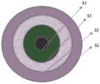
图3为本发明实施例提供的反光棱镜单元的俯视图;3 is a top view of a light-reflecting prism unit provided by an embodiment of the present invention;
图4为本发明实施例提供的背光模组的原理示意图;4 is a schematic diagram of the principle of a backlight module provided by an embodiment of the present invention;
图5为本发明实施例提供的背光模组中光线传播示意图;5 is a schematic diagram of light propagation in a backlight module provided by an embodiment of the present invention;
图6为本发明另一种实施例提供的背光模组的结构示意图。FIG. 6 is a schematic structural diagram of a backlight module provided by another embodiment of the present invention.
具体实施方式Detailed ways
为更进一步阐述本发明为达成预定发明目的所采取的技术手段及功效,以下结合附图及较佳实施例,对依据本发明提出的背光模组其具体实施方式、结构、特征及其功效,详细说明如后。In order to further illustrate the technical means and effects adopted by the present invention to achieve the predetermined purpose of the invention, the following describes the specific implementation, structure, features and effects of the backlight module proposed according to the present invention with reference to the accompanying drawings and preferred embodiments, Details are as follows.
如图1所示,本发明实施例提供了一种背光模组,包括:As shown in FIG. 1, an embodiment of the present invention provides a backlight module, including:
光源层1,光源层1上设有多个发光单元11;a light source layer 1, a plurality of
导光层2,导光层2设置于光源层1的一侧,导光层2背离光源层1的一侧设有多个反光棱镜单元3,多个反光棱镜单元3与多个发光单元11的位置一一对应,反光棱镜单元3用于将发光单元11发出的光线反射至导光层2内,并使光线在所述导光层内传输;The
网点层4,网点层4设置于导光层的一侧,用于将导光层内的光线取出以作为背光光源。The dot layer 4, the dot layer 4 is arranged on one side of the light guide layer, and is used for taking out the light in the light guide layer as a backlight source.
其中,上述的背光模组主要应用于直下式液晶显示器的背光模组,光源层1作为背光模组的光源,其上具有多个发光单元11,该发光单元11可以为LED芯片,LED光源是目前直下式液晶显示器中最常用的背光光源,其具有寿命长、体积小、能耗低等特点,在光源层1上可以均匀设有多个上述的LED芯片作为光源。The above-mentioned backlight module is mainly applied to the backlight module of the direct type liquid crystal display. The light source layer 1 is used as the light source of the backlight module and has a plurality of light-
其中,导光层2可以由透明材质制成,其可以选用ITO或者Si3N4等折射率为1.5的透明介质材料制成,而导光层2的厚度可以为2微米至1mm之间,在此不作具体限定,在导光层2背离光源层1的一侧设有多个反光棱镜单元3,每个发光单元11对应一个反光棱镜单元3,每个发光单元11发出的光线透过导光层2后大部分可以照射在其对应的反光棱镜单元3上,在反光棱镜的作用下,可以将照射在反光棱镜单元3上的光线以全反射的形式在导光层2内全反射传输,然后在导光层2上方设计合适的网点层结构,网点层4可以为光栅结构,可以根据出光情况进行具体设计,导光层2内的光线可以通过网点层的光栅的衍射出导光层2,均匀取光,以实现背光的发光。Wherein, the
本发明实施例提供了一种背光模组,用于减少发光单元的数量以及降低背光模组的厚度,而现有技术中,直下式显示设备的LED光源通过预留混光距离以及增加LED光源密度来提高背光显示的均匀性,但是这样不仅会增加显示设备的厚度,还会增加成本。与现有技术相比,本申请文件提供的背光模组,包括:光源层、导光层和网点层,其中,光源层上设有多个发光单元,导光层设置于光源层的一侧,导光层背离光源层的一侧设有多个反光棱镜单元,多个反光棱镜单元与多个发光单元的位置一一对应,反光棱镜单元用于将发光单元发出的光线反射耦合至导光层内,而网点层能够将导光层内的光线取出以作为背光光源,由于导光层为背光源,而非发光单元作为背光源,所以可以减小发光单元的密度,降低成本,又由于导光层的厚度远小于现有技术中LED光源的预留混光距离,进而可以减小显示设备的厚度。An embodiment of the present invention provides a backlight module for reducing the number of light-emitting units and reducing the thickness of the backlight module. In the prior art, the LED light source of a direct-lit display device is designed by reserving a light mixing distance and increasing the LED light source. Density to improve the uniformity of the backlight display, but this will not only increase the thickness of the display device, but also increase the cost. Compared with the prior art, the backlight module provided by this application document includes: a light source layer, a light guide layer and a dot layer, wherein the light source layer is provided with a plurality of light emitting units, and the light guide layer is arranged on one side of the light source layer. The side of the light guide layer facing away from the light source layer is provided with a plurality of reflective prism units, the plurality of reflective prism units correspond to the positions of the plurality of light emitting units one-to-one, and the light reflective prism units are used to reflect and couple the light emitted by the light emitting units to the light guide The dot layer can take out the light in the light guide layer as a backlight source. Since the light guide layer is a backlight source instead of a light-emitting unit as a backlight source, it can reduce the density of the light-emitting unit and reduce the cost. The thickness of the light guide layer is much smaller than the reserved light mixing distance of the LED light source in the prior art, thereby reducing the thickness of the display device.
上述的反光棱镜单元3可以为多种结构样式,如图2、图3所示,可选地,反光棱镜单元3包括:第一棱镜模块31,第一棱镜模块31在导光层2上的第一正投影为圆形,第一正投影的圆心与发光单元11的发光中心相对应,第一棱镜模块31的厚度从边沿向圆心的方向上依次减小,本实施例中,反光棱镜为透明材质制成,其中,第一棱镜模块31的厚度从边沿向圆心的方向上依次减小,这样就在第一棱镜模块31的中部形成凹槽,该凹槽可以为锥形槽,也可以为半球形槽,在此不作具体限定;如图4所示,由发光单元11发出的光线经过导光层2进入至反光棱镜单元3时,由于第一棱镜模块31的上表面与导光层2之间的夹角为a,而光线在第一棱镜模块31的反射角为a1,通过合理设计夹角a的角度,可以使入射光线在第一棱镜模块31的斜面发生全反射,使进入第一棱镜模块31的光线全反射至导光层2内,经第一棱镜模块31反射的光线经过基底时的入射角为b,同样可以通过合理设计a的角度,使反射光线以全反射形式在导光层2内传输,进而实现发光单元11发出的光线在导光层2内传输的目的,而且上述的第一棱镜模块的结构简单,降低了生产成本。The above-mentioned light-reflecting
由于发光单元11的发光角度为发散状,为了进一步发射更多的光线进入至导光层2内,如图2、图3、图5所示,可选地,反光棱镜单元3还包括:至少一个第二棱镜模块32,每个第二棱镜模块32在导光层2上的第二正投影为圆环形,多个第二棱镜模块32依次环绕于第一棱镜模块31且均与第一棱镜模块31同心设置,每个第二棱镜模块32的厚度从边沿向圆心的方向上依次减小。本实施例中,多个第二棱镜模块32一侧环绕于第一棱镜模块31,例如:多个第二棱镜模块32包括分别正投影为圆环形的第一子模块、第二子模块和第三子模块,其中,第一子模块环绕于第一棱镜模块31,第二子模块环绕于第一子模块,第三子模块环绕于第二子模块,使第一棱镜模块31、第一子模块、第二子模块和第三子模块之间彼此相互衔接,以组成上述的反光棱镜单元3,上述的第二棱镜模块32的径向截面形状可以为直角三角形,而直角三角形的斜边为第二棱镜模块32的上表面,每个第二棱镜模块32的反射原理与第一棱镜模块31的反射原理相同,在此不作赘述,通过多个第二棱镜模块32的设置,可以增加反光棱镜单元3的覆盖面积,进而可以增加发光单元11的光线的反射率,以使更多的光线进入至导光层内传输。Since the light-emitting angle of the light-emitting
进一步的,第一棱镜模块中背离于导光层的面为第一面,第一面在第一棱镜模块的径向截面中形成第一直线;每个第二棱镜模块中背离于导光层的面为第二面,每个第二面在第二棱镜模块的径向截面中形成第二直线。本实施例中,在第一棱镜模块中背离于导光层的面为第一面,而第一面为第一棱镜模块的凹陷面,又由于该第一面在第一棱镜模块的径向截面中为直线状的第一直线,所以该第一面为倒锥形曲面,由于在第一棱镜模块的径向截面中,第一直线用于对光线进行反射,并且可以通过第一直线与导光层之间的夹角设计来实现光线的全反射,进而提高了背光的均匀性;同理,上述第二棱镜模块在径向截面中的第二直线,同样可以通过调节第二直线与导光层之间的角度设计来实现光线的全反射,进而提高了背光的均匀性。Further, the face of the first prism module facing away from the light guide layer is the first face, and the first face forms a first straight line in the radial section of the first prism module; each second prism module faces away from the light guide layer. The faces of the layers are second faces, each second face forming a second straight line in the radial cross-section of the second prismatic module. In this embodiment, the surface of the first prism module facing away from the light guide layer is the first surface, and the first surface is the concave surface of the first prism module, and because the first surface is in the radial direction of the first prism module The cross section is a straight first straight line, so the first surface is an inverted conical curved surface, because in the radial cross section of the first prism module, the first straight line is used to reflect light and can pass through the first prism module. The angle between the straight line and the light guide layer is designed to realize the total reflection of light, thereby improving the uniformity of the backlight. Similarly, the second straight line in the radial section of the second prism module can also be adjusted by adjusting the The angle between the two straight lines and the light guide layer is designed to achieve total reflection of light, thereby improving the uniformity of the backlight.
为了使照射到发光棱镜单元的光线全部实现全反射,可选地,第一直线与导光板之间的夹角为第一夹角,多个第二直线与导光板之间的夹角分别为多个第二夹角,第一夹角的角度大于任意一个第二夹角的角度,其中,靠近于第一棱镜模块31的第二棱镜模块32的第二夹角角度大于远离于第一棱镜模块31的第二棱镜模块32的第二夹角角度。本实施例中,由于多个第二棱镜模块32依次远离于第一棱镜模块31的圆心,使θ的角度逐步变大,如图4、图5所示,随着θ角的增加将会导致导光层内光线的输入角度的增加,如果入射角度过大,将会使导光层内的光线射出导光层,无法在导光层内传播,为了保证光线能够在导光层内传播,可以通过减小a的角度来减小光线在导光层内的反射角角度,所以距离圆心越远的第二棱镜模块的第二夹角越小,以使发射光线能够在导光层内传输。In order to realize total reflection of all the light irradiated to the light-emitting prism unit, optionally, the included angle between the first straight line and the light guide plate is the first included angle, and the included angles between the plurality of second straight lines and the light guide plate are respectively is a plurality of second included angles, the angle of the first included angle is greater than the angle of any one of the second included angles, wherein, the second included angle of the
进一步的,第一棱镜模块31和多个第二棱镜模块32为一体成型结构。本实施例中,由于第一棱镜模块31和多个第二棱镜模块32为一体成型结构,这样相邻两个棱镜模块之间就不会产生间隙,使发光单元11发出的预设角度范围内的光线可以全部通过反光棱镜单元3反射至导光层2内,避免漏光现象的发生,另外,一体成型结构的反光棱镜单元3加工和装配都更加的方便。Further, the
上述背光模组除了具有导光层2和光源层1外,还可以具有其他的功能层,如图1所示,具体的,还包括扩散层5和棱镜膜6,其中,扩散层5设置于网点层4远离导光层2的一侧,棱镜膜6设置于扩散层5远离网点层4的一侧。本实施例中,扩散层5可以为高透光率的聚合物(例如:聚碳酸醋等)和掺杂在其中的散射颗粒(如二氧化钛等)组成,也可以为多层膜的层叠结构,扩散层5用于将射入至扩散层5内的光线进行散射,以实现背光光强的均匀分布;棱镜膜6可以由一个具有尖角微棱镜结构的棱镜层和一个基板层贴合而成,其主要作用为将光线进一步的扩散,以保证背光光强的均匀性。In addition to the
进一步的,上述背光模组还可以包括反射层7,反射层7设置于导光层2背离于网点层4的一侧。本实施例中,通过反射层7的设置,可以将照射到反射层7的光线全反向向上反射,使得光线可以重新作为背光应用,上述的反射层7可以为金属膜层,也可以为多层介质膜,在此不作具体限定。Further, the above-mentioned backlight module may further include a
上述光源层1相对于反射层7和网点层4的设置位置至少可以有两种,如图6所示,可选地,光源层1设置于导光层2和网点层4之间,多个反射棱镜单元设置于反射层7与导光层2之间。该背光模组结构可以为LED底发射形式的背光模组结构,如图1所示,可选地,光源层1设置于反射层7与导光层2之间,多个反射棱镜单元设置于导光层2和网点层4之间。该背光模组结构可以为LED顶发射形式的背光模组结构,所以根据显示设备的形式不同,上述的背光模组可以为多种结构样式,在此不作一一限定。The above-mentioned light source layer 1 can be arranged in at least two positions relative to the
另一方面,本发明实施例还提供了一种显示设备,包括:上述的背光模组。On the other hand, an embodiment of the present invention further provides a display device, comprising: the above-mentioned backlight module.
本发明实施例提供了一种显示设备,用于减少发光单元的数量以及背光模组的厚度,而现有技术中,直下式显示设备的LED光源通过预留混光距离以及增加LED光源密度来提高背光显示的均匀性,但是这样不仅会增加显示设备的厚度,还会增加成本。与现有技术相比,本申请文件提供的显示设备,包括:光源层和导光层,其中,光源层上设有多个发光单元,导光层设置于光源层的一侧,导光层背离光源层的一侧设有多个反光棱镜单元,多个反光棱镜单元与多个发光单元的位置一一对应,反光棱镜单元用于将发光单元发出的光线反射耦合至导光层内,而网点层能够将导光层内的光线取出以作为背光光源,由于导光层为背光源,而非发光单元作为背光源,所以可以减小发光单元的密度,降低成本,又由于导光层的厚度元小于现有技术中LED光源的预留混光距离,进而可以减小显示设备的厚度。The embodiment of the present invention provides a display device for reducing the number of light-emitting units and the thickness of the backlight module. In the prior art, the LED light source of the direct type display device is obtained by reserving a light mixing distance and increasing the density of the LED light source. Improve the uniformity of the backlight display, but this will not only increase the thickness of the display device, but also increase the cost. Compared with the prior art, the display device provided by this application document includes: a light source layer and a light guide layer, wherein the light source layer is provided with a plurality of light emitting units, the light guide layer is arranged on one side of the light source layer, and the light guide layer The side away from the light source layer is provided with a plurality of light-reflecting prism units, the positions of the plurality of light-reflecting prism units correspond to the positions of the plurality of light-emitting units one-to-one, and the light-reflecting prism units are used to reflect and couple the light emitted by the light-emitting units into the light guide layer, and The dot layer can take out the light in the light guide layer as a backlight source. Since the light guide layer is a backlight source instead of a light-emitting unit as a backlight source, the density of the light-emitting unit can be reduced, and the cost can be reduced. The thickness element is smaller than the reserved light mixing distance of the LED light source in the prior art, so that the thickness of the display device can be reduced.
以上所述,仅为本发明的具体实施方式,但本发明的保护范围并不局限于此,任何熟悉本技术领域的技术人员在本发明揭露的技术范围内,可轻易想到变化或替换,都应涵盖在本发明的保护范围之内。因此,本发明的保护范围应以所述权利要求的保护范围为准。The above are only specific embodiments of the present invention, but the protection scope of the present invention is not limited to this. Any person skilled in the art can easily think of changes or substitutions within the technical scope disclosed by the present invention. should be included within the protection scope of the present invention. Therefore, the protection scope of the present invention should be based on the protection scope of the claims.
Claims (7)
Priority Applications (3)
| Application Number | Priority Date | Filing Date | Title |
|---|---|---|---|
| CN201810297117.9ACN108287438B (en) | 2018-03-30 | 2018-03-30 | Backlight module and display device |
| US16/497,524US11131798B2 (en) | 2018-03-30 | 2019-03-26 | Backlight module and display device |
| PCT/CN2019/079664WO2019184906A1 (en) | 2018-03-30 | 2019-03-26 | Backlight module and display device |
Applications Claiming Priority (1)
| Application Number | Priority Date | Filing Date | Title |
|---|---|---|---|
| CN201810297117.9ACN108287438B (en) | 2018-03-30 | 2018-03-30 | Backlight module and display device |
Publications (2)
| Publication Number | Publication Date |
|---|---|
| CN108287438A CN108287438A (en) | 2018-07-17 |
| CN108287438Btrue CN108287438B (en) | 2020-11-27 |
Family
ID=62834238
Family Applications (1)
| Application Number | Title | Priority Date | Filing Date |
|---|---|---|---|
| CN201810297117.9AActiveCN108287438B (en) | 2018-03-30 | 2018-03-30 | Backlight module and display device |
Country Status (3)
| Country | Link |
|---|---|
| US (1) | US11131798B2 (en) |
| CN (1) | CN108287438B (en) |
| WO (1) | WO2019184906A1 (en) |
Families Citing this family (19)
| Publication number | Priority date | Publication date | Assignee | Title |
|---|---|---|---|---|
| GB2484713A (en) | 2010-10-21 | 2012-04-25 | Optovate Ltd | Illumination apparatus |
| GB201718307D0 (en) | 2017-11-05 | 2017-12-20 | Optovate Ltd | Display apparatus |
| GB201800574D0 (en) | 2018-01-14 | 2018-02-28 | Optovate Ltd | Illumination apparatus |
| CN108287438B (en)* | 2018-03-30 | 2020-11-27 | 京东方科技集团股份有限公司 | Backlight module and display device |
| GB201807747D0 (en) | 2018-05-13 | 2018-06-27 | Optovate Ltd | Colour micro-LED display apparatus |
| TWI676067B (en)* | 2018-05-15 | 2019-11-01 | 友達光電股份有限公司 | Display device having ambient light compensation design |
| CN109031788A (en)* | 2018-08-31 | 2018-12-18 | 青岛海信电器股份有限公司 | A kind of backlight module and display device |
| CN109283745B (en)* | 2018-11-29 | 2022-03-01 | 厦门天马微电子有限公司 | Direct type backlight module and display device |
| TW202102883A (en) | 2019-07-02 | 2021-01-16 | 美商瑞爾D斯帕克有限責任公司 | Directional display apparatus |
| EP4028805A4 (en)* | 2019-09-11 | 2023-10-18 | RealD Spark, LLC | Switchable illumination apparatus and privacy display |
| EP4038313A4 (en) | 2019-10-03 | 2023-11-22 | RealD Spark, LLC | Illumination apparatus comprising passive optical nanostructures |
| US11531232B2 (en)* | 2020-01-24 | 2022-12-20 | Brightview Technologies, Inc. | Optical film for back light unit and back light unit including same |
| WO2022271582A1 (en) | 2021-06-22 | 2022-12-29 | Reald Spark, Llc | Illumination apparatus |
| CN113589590A (en)* | 2021-07-21 | 2021-11-02 | 武汉华星光电技术有限公司 | Backlight module and display device |
| US11927790B2 (en) | 2021-07-21 | 2024-03-12 | Wuhan China Star Optoelectronics Technology Co., Ltd. | Backlight module and display device |
| CN114019601B (en)* | 2022-01-06 | 2022-04-05 | 扬昕科技(苏州)有限公司 | Light collecting type light guide assembly and backlight module thereof |
| CN115377273B (en)* | 2022-06-23 | 2024-07-23 | 厦门天马微电子有限公司 | Light-emitting panel, display device and backlight module |
| CN221079143U (en) | 2023-05-22 | 2024-06-04 | 亮视技术公司 | Backlight unit |
| CN117523998A (en)* | 2023-08-08 | 2024-02-06 | 武汉华星光电技术有限公司 | A kind of light panel and display panel |
Citations (2)
| Publication number | Priority date | Publication date | Assignee | Title |
|---|---|---|---|---|
| CN206429949U (en)* | 2016-12-22 | 2017-08-22 | 青岛骐骥光电科技有限公司 | A kind of multi-sheet printed optical sheet |
| CN207133459U (en)* | 2017-09-21 | 2018-03-23 | 合肥京东方显示光源有限公司 | Light guide plate, backlight and display device |
Family Cites Families (22)
| Publication number | Priority date | Publication date | Assignee | Title |
|---|---|---|---|---|
| US6989873B2 (en) | 2003-03-19 | 2006-01-24 | Toppoly Optoelectronics Corp. | Backlight module and liquid crystal display formed therefrom |
| KR100574366B1 (en)* | 2003-12-08 | 2006-04-27 | 엘지.필립스 엘시디 주식회사 | LCD Display Module |
| JP4360945B2 (en)* | 2004-03-10 | 2009-11-11 | シチズン電子株式会社 | Lighting device |
| KR100657284B1 (en) | 2004-11-03 | 2006-12-14 | 삼성전자주식회사 | Backlight unit and LCD using the same |
| JP2006318700A (en)* | 2005-05-11 | 2006-11-24 | Sony Corp | Backlight device and liquid crystal display |
| JP4280283B2 (en)* | 2006-01-27 | 2009-06-17 | 株式会社オプトデザイン | Surface illumination light source device and surface illumination device using the same |
| CN101093315A (en)* | 2006-06-23 | 2007-12-26 | 立碁电子工业股份有限公司 | Surface light source and surface light source module |
| JP4900439B2 (en)* | 2008-10-01 | 2012-03-21 | 三菱電機株式会社 | Planar light source device and display device using the same |
| WO2010058625A1 (en)* | 2008-11-20 | 2010-05-27 | シャープ株式会社 | Illuminating device, display device and television receiving device |
| JP5568263B2 (en)* | 2009-08-06 | 2014-08-06 | 株式会社ジャパンディスプレイ | Liquid crystal display |
| USRE47656E1 (en)* | 2009-08-27 | 2019-10-22 | Lg Electronics Inc. | Optical assembly, backlight unit and display apparatus thereof |
| CN102042562B (en)* | 2009-10-16 | 2013-07-03 | 清华大学 | Light conducting board and back light module |
| KR101131150B1 (en)* | 2010-02-25 | 2012-03-28 | 에스에스씨피 주식회사 | A backlight unitBLU for display device using LEDs |
| US8641219B1 (en)* | 2010-06-17 | 2014-02-04 | Rockwell Collins, Inc. | High efficiency rear lit waveguide |
| CN103672568A (en)* | 2012-09-04 | 2014-03-26 | 展晶科技(深圳)有限公司 | Direct type backlight module |
| TW201433864A (en)* | 2013-02-27 | 2014-09-01 | Wistron Corp | Light-emitting diode backlight module |
| CN203162752U (en)* | 2013-04-02 | 2013-08-28 | 创维液晶器件(深圳)有限公司 | Direct-type liquid crystal display device, backlight module thereof and diffusion plate |
| JP6691449B2 (en)* | 2016-07-11 | 2020-04-28 | 富士フイルム株式会社 | Area lighting device |
| CN107315280B (en)* | 2017-07-28 | 2020-02-21 | 京东方科技集团股份有限公司 | Backlight module and its manufacturing method, display device |
| CN107505769B (en) | 2017-08-15 | 2021-02-26 | 京东方科技集团股份有限公司 | Backlight structure and display device |
| EP3547377B1 (en)* | 2018-03-26 | 2021-06-30 | Nichia Corporation | Method of manufacturing light emitting module, and light emitting module |
| CN108287438B (en)* | 2018-03-30 | 2020-11-27 | 京东方科技集团股份有限公司 | Backlight module and display device |
- 2018
- 2018-03-30CNCN201810297117.9Apatent/CN108287438B/enactiveActive
- 2019
- 2019-03-26WOPCT/CN2019/079664patent/WO2019184906A1/ennot_activeCeased
- 2019-03-26USUS16/497,524patent/US11131798B2/enactiveActive
Patent Citations (2)
| Publication number | Priority date | Publication date | Assignee | Title |
|---|---|---|---|---|
| CN206429949U (en)* | 2016-12-22 | 2017-08-22 | 青岛骐骥光电科技有限公司 | A kind of multi-sheet printed optical sheet |
| CN207133459U (en)* | 2017-09-21 | 2018-03-23 | 合肥京东方显示光源有限公司 | Light guide plate, backlight and display device |
Also Published As
| Publication number | Publication date |
|---|---|
| US20200379160A1 (en) | 2020-12-03 |
| US11131798B2 (en) | 2021-09-28 |
| CN108287438A (en) | 2018-07-17 |
| WO2019184906A1 (en) | 2019-10-03 |
Similar Documents
| Publication | Publication Date | Title |
|---|---|---|
| CN108287438B (en) | Backlight module and display device | |
| US10437099B2 (en) | Backlight module, display panel and display device | |
| JP5360172B2 (en) | Planar light source device and display device using the same | |
| TWI235807B (en) | Light guiding board, and lighting device, plane light source device and display device using the light guiding board | |
| CN104503129B (en) | A kind of optics module and reflection display device | |
| CN206975244U (en) | Light guide plate, backlight module and display device | |
| CN107315280B (en) | Backlight module and its manufacturing method, display device | |
| CN211741790U (en) | Light source module and display device | |
| TWI711864B (en) | Light source module and display device | |
| JP2012504253A (en) | Light guide device | |
| CN110969958B (en) | an LED display | |
| CN101676620A (en) | Liquid crystal display device, backlight module and light-emitting unit | |
| CN113514983B (en) | Backlight module and display device | |
| CN110928038A (en) | Backlight module, display device and liquid crystal television | |
| JPWO2011135627A1 (en) | Planar light source device and display device using the same | |
| TWI255356B (en) | Light guide plate and plane light source using the same | |
| JP2022534283A (en) | Screen fingerprint component and terminal equipment | |
| CN112987410A (en) | Front light source and display device | |
| JP7624688B2 (en) | Surface light source device and flat panel display device | |
| CN107631204A (en) | Light source module and display device | |
| JP4544182B2 (en) | Illumination device, electro-optical device, and manufacturing method thereof | |
| JP2007256697A (en) | Liquid crystal display | |
| CN110426871A (en) | A kind of backlight adjustment structure and display device | |
| TWI275871B (en) | Backlight system | |
| CN111273486B (en) | Light collimation device, backlight module and display panel |
Legal Events
| Date | Code | Title | Description |
|---|---|---|---|
| PB01 | Publication | ||
| PB01 | Publication | ||
| SE01 | Entry into force of request for substantive examination | ||
| SE01 | Entry into force of request for substantive examination | ||
| GR01 | Patent grant | ||
| GR01 | Patent grant |