CN108270264B - Portable tower with electrical outlet - Google Patents
Portable tower with electrical outletDownload PDFInfo
- Publication number
- CN108270264B CN108270264BCN201810007348.1ACN201810007348ACN108270264BCN 108270264 BCN108270264 BCN 108270264BCN 201810007348 ACN201810007348 ACN 201810007348ACN 108270264 BCN108270264 BCN 108270264B
- Authority
- CN
- China
- Prior art keywords
- housing portion
- electrical
- power
- outlet
- portable tower
- Prior art date
- Legal status (The legal status is an assumption and is not a legal conclusion. Google has not performed a legal analysis and makes no representation as to the accuracy of the status listed.)
- Active
Links
Images


Classifications
- H—ELECTRICITY
- H01—ELECTRIC ELEMENTS
- H01R—ELECTRICALLY-CONDUCTIVE CONNECTIONS; STRUCTURAL ASSOCIATIONS OF A PLURALITY OF MUTUALLY-INSULATED ELECTRICAL CONNECTING ELEMENTS; COUPLING DEVICES; CURRENT COLLECTORS
- H01R25/00—Coupling parts adapted for simultaneous co-operation with two or more identical counterparts, e.g. for distributing energy to two or more circuits
- H01R25/003—Coupling parts adapted for simultaneous co-operation with two or more identical counterparts, e.g. for distributing energy to two or more circuits the coupling part being secured only to wires or cables
- A—HUMAN NECESSITIES
- A47—FURNITURE; DOMESTIC ARTICLES OR APPLIANCES; COFFEE MILLS; SPICE MILLS; SUCTION CLEANERS IN GENERAL
- A47C—CHAIRS; SOFAS; BEDS
- A47C7/00—Parts, details, or accessories of chairs or stools
- A47C7/62—Accessories for chairs
- A47C7/72—Adaptations for incorporating lamps, radio sets, bars, telephones, ventilation, heating or cooling arrangements or the like
- A47C7/725—Adaptations for incorporating lamps, radio sets, bars, telephones, ventilation, heating or cooling arrangements or the like for illumination, e.g. lamps
- G—PHYSICS
- G06—COMPUTING OR CALCULATING; COUNTING
- G06F—ELECTRIC DIGITAL DATA PROCESSING
- G06F1/00—Details not covered by groups G06F3/00 - G06F13/00 and G06F21/00
- G06F1/26—Power supply means, e.g. regulation thereof
- H—ELECTRICITY
- H01—ELECTRIC ELEMENTS
- H01R—ELECTRICALLY-CONDUCTIVE CONNECTIONS; STRUCTURAL ASSOCIATIONS OF A PLURALITY OF MUTUALLY-INSULATED ELECTRICAL CONNECTING ELEMENTS; COUPLING DEVICES; CURRENT COLLECTORS
- H01R13/00—Details of coupling devices of the kinds covered by groups H01R12/70 or H01R24/00 - H01R33/00
- H01R13/66—Structural association with built-in electrical component
- H01R13/665—Structural association with built-in electrical component with built-in electronic circuit
- H01R13/6666—Structural association with built-in electrical component with built-in electronic circuit with built-in overvoltage protection
- H—ELECTRICITY
- H01—ELECTRIC ELEMENTS
- H01R—ELECTRICALLY-CONDUCTIVE CONNECTIONS; STRUCTURAL ASSOCIATIONS OF A PLURALITY OF MUTUALLY-INSULATED ELECTRICAL CONNECTING ELEMENTS; COUPLING DEVICES; CURRENT COLLECTORS
- H01R24/00—Two-part coupling devices, or either of their cooperating parts, characterised by their overall structure
- H01R24/28—Coupling parts carrying pins, blades or analogous contacts and secured only to wire or cable
- H01R24/30—Coupling parts carrying pins, blades or analogous contacts and secured only to wire or cable with additional earth or shield contacts
- H—ELECTRICITY
- H01—ELECTRIC ELEMENTS
- H01R—ELECTRICALLY-CONDUCTIVE CONNECTIONS; STRUCTURAL ASSOCIATIONS OF A PLURALITY OF MUTUALLY-INSULATED ELECTRICAL CONNECTING ELEMENTS; COUPLING DEVICES; CURRENT COLLECTORS
- H01R25/00—Coupling parts adapted for simultaneous co-operation with two or more identical counterparts, e.g. for distributing energy to two or more circuits
- H01R25/006—Coupling parts adapted for simultaneous co-operation with two or more identical counterparts, e.g. for distributing energy to two or more circuits the coupling part being secured to apparatus or structure, e.g. duplex wall receptacle
- H—ELECTRICITY
- H01—ELECTRIC ELEMENTS
- H01R—ELECTRICALLY-CONDUCTIVE CONNECTIONS; STRUCTURAL ASSOCIATIONS OF A PLURALITY OF MUTUALLY-INSULATED ELECTRICAL CONNECTING ELEMENTS; COUPLING DEVICES; CURRENT COLLECTORS
- H01R31/00—Coupling parts supported only by co-operation with counterpart
- H01R31/02—Intermediate parts for distributing energy to two or more circuits in parallel, e.g. splitter
- H—ELECTRICITY
- H02—GENERATION; CONVERSION OR DISTRIBUTION OF ELECTRIC POWER
- H02G—INSTALLATION OF ELECTRIC CABLES OR LINES, OR OF COMBINED OPTICAL AND ELECTRIC CABLES OR LINES
- H02G3/00—Installations of electric cables or lines or protective tubing therefor in or on buildings, equivalent structures or vehicles
- H02G3/02—Details
- H02G3/04—Protective tubing or conduits, e.g. cable ladders or cable troughs
- H02G3/0493—Service poles
- H—ELECTRICITY
- H02—GENERATION; CONVERSION OR DISTRIBUTION OF ELECTRIC POWER
- H02J—CIRCUIT ARRANGEMENTS OR SYSTEMS FOR SUPPLYING OR DISTRIBUTING ELECTRIC POWER; SYSTEMS FOR STORING ELECTRIC ENERGY
- H02J4/00—Circuit arrangements for mains or distribution networks not specified as AC or DC
- H—ELECTRICITY
- H02—GENERATION; CONVERSION OR DISTRIBUTION OF ELECTRIC POWER
- H02J—CIRCUIT ARRANGEMENTS OR SYSTEMS FOR SUPPLYING OR DISTRIBUTING ELECTRIC POWER; SYSTEMS FOR STORING ELECTRIC ENERGY
- H02J7/00—Circuit arrangements for charging or depolarising batteries or for supplying loads from batteries
- H02J7/0013—Circuit arrangements for charging or depolarising batteries or for supplying loads from batteries acting upon several batteries simultaneously or sequentially
- H—ELECTRICITY
- H02—GENERATION; CONVERSION OR DISTRIBUTION OF ELECTRIC POWER
- H02J—CIRCUIT ARRANGEMENTS OR SYSTEMS FOR SUPPLYING OR DISTRIBUTING ELECTRIC POWER; SYSTEMS FOR STORING ELECTRIC ENERGY
- H02J7/00—Circuit arrangements for charging or depolarising batteries or for supplying loads from batteries
- H02J7/0042—Circuit arrangements for charging or depolarising batteries or for supplying loads from batteries characterised by the mechanical construction
- H02J7/0044—Circuit arrangements for charging or depolarising batteries or for supplying loads from batteries characterised by the mechanical construction specially adapted for holding portable devices containing batteries
- H—ELECTRICITY
- H01—ELECTRIC ELEMENTS
- H01R—ELECTRICALLY-CONDUCTIVE CONNECTIONS; STRUCTURAL ASSOCIATIONS OF A PLURALITY OF MUTUALLY-INSULATED ELECTRICAL CONNECTING ELEMENTS; COUPLING DEVICES; CURRENT COLLECTORS
- H01R13/00—Details of coupling devices of the kinds covered by groups H01R12/70 or H01R24/00 - H01R33/00
- H01R13/66—Structural association with built-in electrical component
- H01R13/665—Structural association with built-in electrical component with built-in electronic circuit
- H01R13/6675—Structural association with built-in electrical component with built-in electronic circuit with built-in power supply
- H—ELECTRICITY
- H01—ELECTRIC ELEMENTS
- H01R—ELECTRICALLY-CONDUCTIVE CONNECTIONS; STRUCTURAL ASSOCIATIONS OF A PLURALITY OF MUTUALLY-INSULATED ELECTRICAL CONNECTING ELEMENTS; COUPLING DEVICES; CURRENT COLLECTORS
- H01R13/00—Details of coupling devices of the kinds covered by groups H01R12/70 or H01R24/00 - H01R33/00
- H01R13/66—Structural association with built-in electrical component
- H01R13/70—Structural association with built-in electrical component with built-in switch
- H—ELECTRICITY
- H01—ELECTRIC ELEMENTS
- H01R—ELECTRICALLY-CONDUCTIVE CONNECTIONS; STRUCTURAL ASSOCIATIONS OF A PLURALITY OF MUTUALLY-INSULATED ELECTRICAL CONNECTING ELEMENTS; COUPLING DEVICES; CURRENT COLLECTORS
- H01R2103/00—Two poles
- H—ELECTRICITY
- H01—ELECTRIC ELEMENTS
- H01R—ELECTRICALLY-CONDUCTIVE CONNECTIONS; STRUCTURAL ASSOCIATIONS OF A PLURALITY OF MUTUALLY-INSULATED ELECTRICAL CONNECTING ELEMENTS; COUPLING DEVICES; CURRENT COLLECTORS
- H01R27/00—Coupling parts adapted for co-operation with two or more dissimilar counterparts
- H01R27/02—Coupling parts adapted for co-operation with two or more dissimilar counterparts for simultaneous co-operation with two or more dissimilar counterparts
- H—ELECTRICITY
- H02—GENERATION; CONVERSION OR DISTRIBUTION OF ELECTRIC POWER
- H02J—CIRCUIT ARRANGEMENTS OR SYSTEMS FOR SUPPLYING OR DISTRIBUTING ELECTRIC POWER; SYSTEMS FOR STORING ELECTRIC ENERGY
- H02J2310/00—The network for supplying or distributing electric power characterised by its spatial reach or by the load
- H02J2310/10—The network having a local or delimited stationary reach
- H02J2310/20—The network being internal to a load
- H02J2310/22—The load being a portable electronic device
- H—ELECTRICITY
- H02—GENERATION; CONVERSION OR DISTRIBUTION OF ELECTRIC POWER
- H02J—CIRCUIT ARRANGEMENTS OR SYSTEMS FOR SUPPLYING OR DISTRIBUTING ELECTRIC POWER; SYSTEMS FOR STORING ELECTRIC ENERGY
- H02J7/00—Circuit arrangements for charging or depolarising batteries or for supplying loads from batteries
- H02J7/34—Parallel operation in networks using both storage and other DC sources, e.g. providing buffering
- H02J7/342—The other DC source being a battery actively interacting with the first one, i.e. battery to battery charging
Landscapes
- Engineering & Computer Science (AREA)
- Power Engineering (AREA)
- Theoretical Computer Science (AREA)
- Architecture (AREA)
- Civil Engineering (AREA)
- Structural Engineering (AREA)
- Microelectronics & Electronic Packaging (AREA)
- Physics & Mathematics (AREA)
- General Engineering & Computer Science (AREA)
- General Physics & Mathematics (AREA)
- Charge And Discharge Circuits For Batteries Or The Like (AREA)
Abstract
Description
Translated fromChinese相关申请的交叉引用CROSS-REFERENCE TO RELATED APPLICATIONS
本申请要求2017年1月4日提交的序列号为62/442022的美国临时申请的权益,其全部内容通过援引并入本文。This application claims the benefit of US Provisional Application Serial No. 62/442022, filed January 4, 2017, the entire contents of which are incorporated herein by reference.
技术领域technical field
本发明涉及一种具有用于电气设备和电子装置的电力和/或数据输出口的便携式物品。The present invention relates to a portable article having a power and/or data outlet for electrical and electronic devices.
背景技术Background technique
由于电气设备和电子装置、尤其是具有可再充电电池的便携式电子装置变得更加普遍,越来越期望提供方便的电输出口,用于对那些设备再充电和/或供电。As electrical devices and electronic devices, especially portable electronic devices with rechargeable batteries, become more prevalent, it is increasingly desirable to provide a convenient electrical outlet for recharging and/or powering those devices.
发明内容SUMMARY OF THE INVENTION
本发明提供了具有电性能的便携式塔架,所述便携式塔架构造成将被支撑在地板、桌子、或其它支撑表面上,并且所述便携式塔架易于被重新定位在期望的位置,以向用户提供方便的电力和/或电子数据信号。在一些实施例中,输出口由架载电源(比如可再充电电池或电容器)供电,所述架载电源能够经由充电线或无线电力发射器再充电。在其他实施例中,输出口由外部电源和/或电子数据源(例如经由墙壁或地板输出口)供电。在更进一步的实施例中,可以使用外部电源和架载电源的组合并且可以由架载控制器控制。便携式塔架具有壳体,所述壳体成形为便于将塔架搁置在地板表面上、并且便于根据需要手动抓握和重新定位塔架。The present invention provides a portable tower with electrical properties that is configured to be supported on a floor, table, or other support surface, and that can be easily repositioned in a desired location to provide user access to Provides convenient electrical and/or electronic data signals. In some embodiments, the outlet is powered by an on-board power source (such as a rechargeable battery or capacitor) that can be recharged via a charging cord or wireless power transmitter. In other embodiments, the outlet is powered by an external power source and/or an electronic data source (eg, via a wall or floor outlet). In still further embodiments, a combination of external power and on-board power can be used and can be controlled by an on-board controller. The portable tower has a housing shaped to facilitate resting the tower on a floor surface and to facilitate manual gripping and repositioning of the tower as needed.
根据本发明的一种形式,具有电性能的便携式塔架包括具有第一电输出口和第二电输出口的壳体以及用于向所述输出口供应电力和/或电子数据信号的电导体。所述壳体包括基座壳体部分,从基座壳体部分向上延伸的直立的中央壳体部分,以及位于所述中央壳体部分的上端处的上部壳体部分。第一电输出口安装在上部壳体部分处,第二电输出口安装在基座壳体部分处。电导体延伸穿过基座壳体部分、穿过直立的中央壳体部分、并穿过上部壳体部分,并且与诸如架载可再充电电池的电源或诸如位于工作区域的墙壁或地板输出口的外部电源电连通。According to one form of the invention, a portable tower having electrical properties includes a housing having a first electrical outlet and a second electrical outlet and electrical conductors for supplying electrical power and/or electronic data signals to the outlets . The housing includes a base housing portion, an upright central housing portion extending upwardly from the base housing portion, and an upper housing portion at an upper end of the central housing portion. The first electrical outlet is mounted at the upper housing portion and the second electrical outlet is mounted at the base housing portion. Electrical conductors extend through the base housing portion, through the upright central housing portion, and through the upper housing portion, and communicate with a power source such as an on-board rechargeable battery or an outlet such as a wall or floor located in the work area. The external power supply is electrically connected.
在一个方面,便携式塔架包括安装在基座壳体部分中的电源,诸如可再充电电池或电容器。可选地,提供了充电插口,该充电插口构造为从与外部电源电连通的连接器接收电力,或者可以在基座壳体部分中提供无线电力接收器,用于从无线电力发射器接收电力,所述无线电力发射器从外部电源(例如墙壁或地板输出口)接收电力。In one aspect, the portable tower includes a power source, such as a rechargeable battery or capacitor, mounted in the base housing portion. Optionally, a charging socket is provided that is configured to receive power from a connector in electrical communication with an external power source, or a wireless power receiver may be provided in the base housing portion for receiving power from a wireless power transmitter , the wireless power transmitter receives power from an external power source such as a wall or floor outlet.
在另一个方面,充电电路将从充电插口或从无线电力接收器接收的电力选择性地引导到电池、电容器、或其他可再充电的电能存储装置。In another aspect, the charging circuit selectively directs power received from the charging socket or from the wireless power receiver to a battery, capacitor, or other rechargeable electrical energy storage device.
在又一个方面,存在供电电路,所述供电电路用于将从电源接收的电力选择性地引导到第一电输出口和第二电输出口。In yet another aspect, there is a power supply circuit for selectively directing power received from the power source to the first electrical outlet and the second electrical outlet.
在又一个方面,电灯被定位在上部壳体部分中,并且被构造为照亮至少所述基座壳体部分。In yet another aspect, an electric light is positioned in the upper housing portion and is configured to illuminate at least the base housing portion.
在另一个方面,第二电输出口包括无线电力发射器,并且基座壳体部分包括上部支撑表面,该上部支撑表面可以在无线电力发射器对便携式电子装置进行无线充电期间支撑便携式电子装置。In another aspect, the second electrical outlet includes a wireless power transmitter, and the base housing portion includes an upper support surface that can support the portable electronic device during wireless charging of the portable electronic device by the wireless power transmitter.
在又一个方面,电力线和插头与第一电输出口和第二电输出口电连通。插头被构造为接合所述电源,从而从所述电源接收电力或电子数据信号。In yet another aspect, a power cord and plug are in electrical communication with the first electrical outlet and the second electrical outlet. The plug is configured to engage the power source to receive power or electronic data signals from the power source.
在又一个方面,第一电输出口包括至少一个低压DC电力输出口。可选地,便携式塔架包括与所述电源和所述低压DC电力输出口电连通的电力转换器。电力转换器被构造为接收来自所述电源的高压AC电力输入并且将低压DC电力输出供应给所述至少一个低压DC电力输出口。可选地,电力转换器安装在直立的中央壳体部分中。In yet another aspect, the first electrical outlet includes at least one low voltage DC electrical outlet. Optionally, the portable tower includes a power converter in electrical communication with the power source and the low voltage DC power outlet. A power converter is configured to receive a high voltage AC power input from the power source and supply a low voltage DC power output to the at least one low voltage DC power outlet. Optionally, the power converter is mounted in an upright central housing portion.
在另一个方面,第二电输出口包括至少一个高压AC电力输出口。In another aspect, the second electrical outlet includes at least one high voltage AC electrical outlet.
可选地,第一电输出口和第二电输出口安装在基座壳体部分和上部壳体部分的相应的面向上的表面上。Optionally, the first electrical outlet and the second electrical outlet are mounted on respective upwardly facing surfaces of the base housing portion and the upper housing portion.
在另一个方面,在上部壳体部分处具有第三电输出口,并且在上部壳体部分中设置有模块化输出口支撑件。模块化输出口支撑件限定单独的开口,每个开口被构造成可互换地接收第一电输出口和第三电输出口中的任一个。In another aspect, there is a third electrical outlet at the upper housing portion, and a modular outlet support is provided in the upper housing portion. The modular outlet support defines separate openings, each of which is configured to interchangeably receive any of the first electrical outlet and the third electrical outlet.
根据本发明的一种形式,具有电性能的便携式塔架包括:壳体,模块化输出口支撑件,第一电输出口和第二电输出口,以及用于向电输出口供应电力和/或电子数据信号的电导体。所述壳体包括基座壳体部分,从基座壳体部分向上延伸的直立的中央壳体部分,以及位于中央壳体部分的上端处的上部壳体部分。模块化输出口支撑件定位在上部壳体部分中,模块化输出口支撑件限定第一开口和第二开口。第一电输出口安装在第一开口中,第二电输出口安装在第二开口中。模块化输出口支撑件构造成将第一电输出口和第二电输出口中的每一个分别支撑在第一开口和第二开口中的任一个中,由此使得第一电输出口和第二电输出口彼此可互换。壳体限定延伸穿过基座壳体部分、直立的中央壳体部分、和上部壳体部分中的每一个的布线通道,电导体延伸穿过所述布线通道,与第一电输出口和第二电输出口电连通,并且还与诸如架载可再充电电池之类的电源或位于工作区域中的诸如墙壁或地板输出口之类的外部电源电连通。According to one form of the invention, a portable tower having electrical properties includes a housing, a modular outlet support, a first electrical outlet and a second electrical outlet, and means for supplying electrical power and/or to the electrical outlet or electrical conductors of electronic data signals. The housing includes a base housing portion, an upright central housing portion extending upwardly from the base housing portion, and an upper housing portion at an upper end of the central housing portion. A modular spout support is positioned in the upper housing portion, the modular spout support defining a first opening and a second opening. The first electrical outlet is mounted in the first opening and the second electrical outlet is mounted in the second opening. The modular outlet support is configured to support each of the first electrical outlet and the second electrical outlet, respectively, in any of the first and second openings, thereby allowing the first electrical outlet and the second electrical outlet, respectively The electrical outlets are interchangeable with each other. The housing defines a wiring channel extending through each of the base housing portion, the upright central housing portion, and the upper housing portion through which electrical conductors extend to communicate with the first electrical outlet and the first electrical outlet. The two electrical outlets are in electrical communication and are also in electrical communication with a power source such as an on-board rechargeable battery or an external power source such as a wall or floor outlet located in the work area.
因此,本发明的便携式塔架为工作区域的用户提供方便和便携的电输出口,例如为便携式电子装置充电或为计算机或电气或电子装置或设备供电。便携式塔架可以具有用于根据特定应用的需要提供不同类型的输出口的模块化能力,例如低压DC电力输出口、高压AC电力输出口、电子数据输出口、或它们的组合。在一些实施例中,便携式塔架可以由与墙壁输出口或地板输出口接合的常规线和插头供电,而在其他实施例中,便携式塔架具有架载可再充电电源,所述架载可再充电电源能够基本上在任何期望的位置处提供至少有限量的DC低压电力,而不依赖于连接至外部电源的线。Thus, the portable tower of the present invention provides a user of a work area with a convenient and portable electrical outlet, such as charging a portable electronic device or powering a computer or electrical or electronic device or equipment. Portable towers may have modular capabilities for providing different types of outlets, such as low voltage DC power outlets, high voltage AC power outlets, electronic data outlets, or a combination thereof, depending on the needs of a particular application. In some embodiments, the portable tower can be powered by a conventional cord and plug that engages with a wall outlet or floor outlet, while in other embodiments, the portable tower has an on-board rechargeable power source that can The recharging power source is capable of providing at least a limited amount of DC low voltage power at substantially any desired location, independent of wires connected to an external power source.
结合附图阅读下面的说明,本发明的这些和其他目标、优点、目的和特征将变得显而易见。These and other objects, advantages, objects and features of the present invention will become apparent from the following description read in conjunction with the accompanying drawings.
附图说明Description of drawings
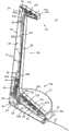
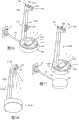
图1是根据本发明的具有电输出口的便携式塔架的透视图;1 is a perspective view of a portable tower having an electrical outlet in accordance with the present invention;
图2是图1的便携式塔架的剖面透视图,其显示了内部结构;Figure 2 is a cutaway perspective view of the portable tower of Figure 1 showing the internal structure;
图2A是图1的便携式塔架的另一个剖面透视图,其显示了包括布线的内部结构;2A is another cutaway perspective view of the portable tower of FIG. 1 showing the internal structure including wiring;
图3是图1的便携式塔架的上部部分的放大的剖面侧视图;3 is an enlarged cross-sectional side view of an upper portion of the portable tower of FIG. 1;
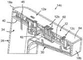
图4是图3的上部部分的透视图;Figure 4 is a perspective view of the upper portion of Figure 3;
图5是图1的便携式塔架的下部部分的放大的剖面侧视图;5 is an enlarged cross-sectional side view of a lower portion of the portable tower of FIG. 1;
图6是图5的下部部分的透视图;Figure 6 is a perspective view of the lower portion of Figure 5;
图7是根据本发明的具有电输出口的无线便携式塔架的上部部分的放大的剖面侧视图;7 is an enlarged cross-sectional side view of an upper portion of a wireless portable tower having an electrical outlet in accordance with the present invention;
图8是图7的上部部分的透视图;Figure 8 is a perspective view of the upper portion of Figure 7;
图9是与图7和图8的上部部分对应的无线便携式塔架的下部部分的放大的剖面侧视图;9 is an enlarged cross-sectional side view of a lower portion of the wireless portable tower corresponding to the upper portion of FIGS. 7 and 8;
图10是图9的下部部分的透视图;Figure 10 is a perspective view of the lower portion of Figure 9;
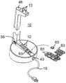
图11是根据本发明的具有模块化电输出口的另一便携式塔架的透视图;11 is a perspective view of another portable tower with modular electrical outlets in accordance with the present invention;
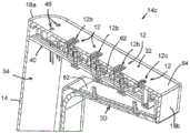
图12是图11的便携式塔架的剖面透视图,其显示了内部结构;Figure 12 is a cutaway perspective view of the portable tower of Figure 11 showing the internal structure;
图13是图11的便携式塔架的下部部分的放大的剖面侧视图;13 is an enlarged cross-sectional side view of a lower portion of the portable tower of FIG. 11;
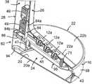
图14是图13的下部部分的透视图;Figure 14 is a perspective view of the lower portion of Figure 13;
图15是图11的便携式塔架的分解透视图;Figure 15 is an exploded perspective view of the portable tower of Figure 11;
图15A和15B是图15中指定了15A和15B的相应区域的放大图;Figures 15A and 15B are enlarged views of the respective regions designated 15A and 15B in Figure 15;
图16是根据本发明的另一种便携式塔架的透视图,所述便携式塔架具有沿着基座部分的电输出口和无线充电性能;16 is a perspective view of another portable tower having an electrical outlet along the base portion and wireless charging capability in accordance with the present invention;
图17是根据本发明的无线充电器与具有电输出口、无线充电性能、和无线再充电性能的另一种无线便携式塔架的组合的透视图;17 is a perspective view of a combination of a wireless charger and another wireless portable tower having an electrical outlet, wireless charging capability, and wireless recharging capability in accordance with the present invention;
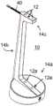
图18是另一个便携式塔架的底部透视图,所述便携式塔架在上部部分中具有电输出口和向下照明的装置;Figure 18 is a bottom perspective view of another portable tower having an electrical outlet in the upper portion and means for downward lighting;
图19是根据本发明的具有模块化电输出口的另一便携式塔架的透视图;19 is a perspective view of another portable tower with modular electrical outlets in accordance with the present invention;
图20是根据本发明的具有电输出口的另一便携式塔架的透视图;和20 is a perspective view of another portable tower having an electrical outlet in accordance with the present invention; and
图21是根据本发明的、仅在其上部部分具有电输出口的另一便携式塔架的透视图。Figure 21 is a perspective view of another portable tower according to the present invention having an electrical outlet only in its upper portion.
具体实施方式Detailed ways
现在参考附图和本文中描述的说明性实施例,便携式塔架10为用户提供了便利的电力和/或数据输出口12,所述输出口12沿着塔架壳体14安装在不同的位置处(图1)。在整个说明书中,术语“电输出口”可以用于指代电力输出口和/或电子数据输出口。塔架壳体14包括基座壳体或基座壳体部分14a、从基座壳体14a向上延伸的直立的中央壳体部分14b、以及定位在中央壳体部分14b的上端处并在基座壳体部分14a上方间隔开的上部壳体或上部壳体部分14c。上部壳体部分14c的尺寸和形状被设计成由用户抓握,以便于将便携式塔架10重新定位到期望的位置,并且定位在足够的高度以便在便携式塔架10搁置在地板或类似支撑表面上时由站着或坐着的用户抓握。各种实施例(包括图1-6、11-16、19和20中的那些实施例)可以经由连接到外部电源17(如图16和19所示)的线15接收电力,而其他实施例(例如图7-10、17和21的实施例)使用例如电池组或其他电力存储装置的架载电源、或者外部电源和架载电源的组合来对其输出口供电。下面将更详细地描述这些和各种其他特征和选项。Referring now to the figures and the illustrative embodiments described herein, the
虽然可以理解的是,便携式塔架的壳体可以有许多不同的形状结构,但是在所示的实施例中,基座壳体部分14a具有基座壳体构件68,当从上方观察时,所述基座壳体构件68具有大致圆形的大致圆形外周边16。上部壳体部分14c具有大致矩形的外周边18,所述外周边18具有圆化的近侧端部18a和方形的远侧端部18b,所述远侧端部18b以悬臂方式在基座壳体部分14a上方横向延伸。中央壳体部分14b从基座壳体部分14a的一侧以倾斜的角度向上延伸,使得当从上方观察时,上部壳体部分14c相对于基座壳体部分14a基本上居中。上部壳体部分14c的整个水平长度小于基座壳体的外周边16的直径,使得当从上方观察便携式塔架10时,外周边将看上去环绕上部壳体部分14c。While it will be appreciated that the housing of the portable tower may have many different shapes and configurations, in the embodiment shown, the
基座壳体部分14a进一步包括底部面板20(具有滑动垫20a)和顶部面板22,如下所述,所述底部面板20和顶部面板22与基座壳体构件68相配合以限定其中安装有电气部件的基座腔体24。顶部面板22包括安装有输出口12的凸起的中央输出口部分22a,其中,凸起的中央输出口部分22a相对于水平并相对于一对外侧顶部面板部分22b成角度,所述一对外侧顶部面板部分22b分别位于中央输出口部分22a的任一侧部上。中央输出口部分22a过渡到中央壳体部分14b的面向内的平坦表面26,中央壳体部分14b还具有面向外的圆化表面28,所述圆化表面28大体从基座壳体部分14a的圆形外周边16延伸到上部壳体部分14c的矩形外周边18的圆化的近侧端部18a。中央壳体部分14b的面向内的平坦表面26过渡到上部壳体部分14c的面向下的底部表面30,所述上部壳体部分14c具有面向上的顶部表面32,所述顶部表面32由大致矩形的外周边18间隔在底部表面30之上,这些表面18、30、32配合以限定安装附加电气部件的上部腔体34,如图2-4所示。The
在所示实施例中,底部表面30相对于水平沿远离中央壳体部分14b的方向向上成角度,而顶部表面32基本上水平并且平行于基座壳体部分14a的底部面板20。中央壳体部分14b的面向内的平坦表面26和面向外的圆化表面28与一对侧表面36配合,以限定细长的中央腔体38,所述中央腔体38至少部分地通向基座腔体24和上部腔体34,以允许布线或其他导体通过,如下所述。中央壳体部分14b可以具有足够的长度,使得上部壳体部分14c的顶部表面32位于其上搁置底部面板20(可选地具有滑动垫20a)的支撑表面上方大约24英寸至36英寸。In the illustrated embodiment, the
可选地,至少中央壳体部分14b和上部壳体部分14c的各个表面可以例如在注射成型操作中由树脂塑料整体地形成。在图1-6所示的实施例中,上部壳体部分14c的顶部表面32和基座壳体部分14a的底部面板20各自被制造成分离的部件,其可被移除以分别暴露上部腔体34和基座腔体24。可选地,并且如下面将更详细地描述的,基座壳体的顶部面板22的凸起的中央输出口部分22a可以容纳不同类型或种类的电输出口12。组装在一起以形成壳体14的各种部件可以使用螺纹紧固件、磁性紧固件、诸如弹性闩锁的卡扣紧固件、或者诸如超声波焊接或粘合剂的更永久的方法来附接。Alternatively, the respective surfaces of at least the
如图1-4所示,上部壳体部分14c处的输出口12包括高压AC电力输出口12a(示出为标准NEMA 110V AC输出口)和低压DC电力输出口12b、12c(示出为USB-A电力输出口12b和USB-C电力输出口12c)。然而,可以理解的是,在不脱离本发明的精神和范围的情况下,可以提供基本上任何构造、类型、电压和容量的高压和/或低压输出口。对于外部供电的(有线的)实施例以及无线的实施例,电线40通过基座腔体24和中央腔体38被布线到上部壳体部分14c的上部腔体34中(图7)。电线夹或保持器41(图2、2A和12)位于中央腔体38的内部,并且用于在电线40穿过基座腔体24和上部腔体34之间的中央腔体38时固定电线40。然而,可以理解的是,如图20所示,用于输出口12的电线40可以通过上部壳体部分14c引出。如参照图2A所理解的,电线40可以包括高压AC线40a和低压DC线40b,所述高压AC线40a携带与电力线15相同的电压,所述低压DC线40b将低压DC电力输送到低压DC输出口12b、12c。As shown in Figures 1-4, the
在图1-6的实施例中,并且如图2A最佳地所示,电力线15通过形成在基座壳体构件68的圆形外周边16中的开口43进入基座壳体14a,在下部插座壳体面板45的大部分的下方经过,然后向上穿过形成在下部插座壳体面板45中的开口中的电线护环(grommet)47。电线护环47形成用于电力线15的90度通道,并且尽管图2A中示出的电力线15的直径远小于穿过电线护环47的通道的内径,但应当理解的是,通道的内径通常将被设计成与电力线15的外部护套形成过盈配合,由此提供应力释放。In the embodiment of FIGS. 1-6, and as best shown in FIG. 2A, the
高压AC线40a可以直接联接到电力线15的导体,然后直接联接到高压AC电力输出口12a的相应的线路端子、中性端子和接地端子,而额外的导体为一对AC至DC电转换器49供应高压AC电力,所述AC至DC电转换器49经由低压DC线40b向位于上部壳体14c中的低压DC输出口12b、12c供应低压DC电力(图2A)。与电力线的布线直接连通的另外的其他导体可以穿过中央壳体部分14b的中央腔体38,并且将电力供应到位于上部壳体14c中的一个或多个高压AC电力输出口12a。因此,如图2A所示,电线夹或保持器41可以固定高压和低压导体。就在某些实施例中期望通过低压导体传输电子数据信号而言,可以理解,适当的电屏蔽件可以用于紧邻高压AC导体的低压导体。The high
可选地,当使用外部线15来供应充电电力(例如,供应到存储装置42)或直接供应电力到输出口12时,可以在基座壳体部分14a中(例如在基座腔体24中)设置旋转的线卷绕器(未示出)。当线未使用时,线卷绕器可操作成选择性地将电力线存储在缩回构造中。进一步构思的是,多余的线可以手动地缠绕在中央壳体部分14b周围。Alternatively, when
便携式塔架10的无线实施例包括可再充电的电能存储装置42,例如电池或电容器,所述电能存储装置42位于基座壳体部分14a的基座腔体24中,如图7和8所示。电池42被支撑在底部面板20顶部,并且能够向位于沿壳体14的大致任何位置处的至少低压DC电输出口12b和/或12c供应有限量的电力。通过将电池42定位在壳体14中的最低位置,所述电池42可以充当用于将便携式塔架10稳定在地板或其他支撑表面上的配重。The wireless embodiment of the
电池42可以经由直接电连接到位于外周边16的前端部处的充电插口44而被再充电。充电插口44构造为在电线的连接到DC变压器(未示出)的端部处由常规的同轴DC电力插头接合,所述DC变压器例如插入到常规的高压AC墙壁输出口或地板输出口中。充电插口44直接向电池42供应充电电力、或通过管理输入的充电电力的充电电路48向电池42供应充电电力,所述充电电路还可以用作供电电路,所述供电电路管理从电池42到低压DC输出口12b和/或12c的电力供应。尽管在图7和8中没有示出,但可以理解的是,具有至少两个导体和至少一个连接器的电线将被用于建立从充电插口44上的端子44a到充电电路48上的连接器48a的电连接,从而使得充电电路的连接器48a与电线的连接器接合。The
如图7和8所示,当便携式塔架10设置有可再充电的电能存储装置42时,设置在上部壳体部分14c和下部壳体部分14a处的电输出口12可以仅限于低压DC电力输出口12b和/或12c,如图9和10所示。此外,在仅有DC的便携式塔架的情况下,AC至DC电转换器49可以省略,如图17和21所示,这是因为虽然电路48可以包括用于将输入的高压AC电力转换成低压DC电力以便对架载电池42进行再充电的AC至DC电转换器,但是来自电池42的输出可以适合于将低压DC电力直接供应到输出口12b、12c。还能够提供DC至AC电转换器,使得高压AC电力输出口12a可以从架载电池42供应适当的电力。As shown in Figures 7 and 8, when the
可选地,并且作为使用直接接触的充电插口44对电池42再充电的代替(或补充),无线电力接收器50可以设置在基座壳体14a中,以用于对电池42再充电和/或用于对输出口12直接供电,如图17所示。无线电力接收器50可操作成从无线电力发射器52接收电力。例如,无线电力传送可以通过感应磁共振联接或电场共振电容联接技术来实现。在另一种布置中,可以通过在基座部分14a的底部面板20处或沿着基座部分14a的底部面板20形成的间隔开的电接收触头来实现基于无线接触的电力传输,其中充电触头形成在兼容的充电基座的上表面处或沿着兼容的充电基座的上表面形成。Alternatively, and in lieu of (or in addition to) recharging the
为便于定制选择设置在基座壳体部分14a和上部壳体部分14c处的电输出口12,便携式塔架10可包括模块化的输出口安装特征件,例如如图11-15B所示。在图11-15B所示的实施例中,便携式塔架10在其基座壳体部分14a处支撑三个高压AC电输出口12a,并且在其上部壳体部分14c处还支撑一个高压AC电输出口12a、在单个输出口组件中的两个USB-A低压DC电输出口12b、以及一个USB-C低压DC电输出口12c。在上部壳体部分14c中,电输出口12a、12b、12c被支撑在形成在用作模块化输出口支撑件的输出口子壳体62中的相应的开口60中。在所示的实施例中,高压和低压输出口12a、12b在他们相应的开口60中是可互换的,而USB-A低压输出口12c在输出口子壳体62中具有较小的开口60。可选地,单独的窗口式插入件63可以用于在如图19所示的较大的开口中支撑较小的或不同形状的输出口,例如USB-A输出口12c。为了便于互换性,使用窗口式插入件63以用于将不同的输出口调整成相同尺寸的开口在共同拥有的美国专利No.7,182,633和7,559,795中进行了更详细的描述,这两个专利的全部内容通过引用结合到本文中。用于将不同的输出口调整成模块化空间的其它结构和方法在共同拥有的美国专利No.8,444,432和8,480,429中公开,这两个专利的全部内容通过引用结合到本文中。To facilitate custom selection of
如图15A所示,上部壳体部分14c的面向上的顶部表面32和远侧端部18b由大致L形的上部壳体盖64形成,所述上盖壳体64具有形成在其中的相应的开口64a,以提供通向输出口12的相应开口的通道并且为状态灯46(或者如图10、17和21所示的多个状态灯46)提供观察通道,所述状态灯46可以用于向用户提供输出口是否通电、可再充电电池中可用的剩余电力、或所需的其他相关信息的视觉指示。上部壳体盖64包括接合输出口子壳体62的相应的侧凸缘62a的向下延伸的闭锁凸片64b,而上部壳体盖64、输出口子壳体62、和输出口12的组件可以通过机械紧固件66固定到矩形的外周边18和底部壳体表面30。As shown in FIG. 15A, the upwardly facing
现在参考图15和15B,示出了组装在一起以形成便携式塔架10的整个下部区域的部件,所述部件包括中央壳体部分14b的形成凸起的中央输出口部分22a的下端部、外侧顶部面板部分22b、电输出口12、包括大致圆形的外周边16的基座壳体构件68、和底部面板20。一对支撑板70a、70b具有用于安装位于凸起的中央输出口部分22a处的输出口12和断路器71的相应的开口72,因此用作模块化输出口支撑件。中央输出口部分22a包括相应的开口74,输出口12和断路器71的上表面或上部分可以穿过开口74突出,如图5、6和11-14所示。以与如上所述的输出口12a、12b、12c和状态灯46使用输出口子壳体62安装在上部壳体部分14c中基本相同的方式,输出口12和断路器71可以被安装到支撑板70a、70b,并且通过凸起的中央输出口部分22a中的开口74而变得可接近或可见。尽管示出了两个支撑板70a、70b,但是应该理解,单个支撑板也可以用作模块化输出口支撑件。Referring now to Figures 15 and 15B, there are shown components assembled together to form the entire lower region of the
中央壳体部分14b的下端部通过机械紧固件66安装到基座壳体构件68,机械紧固件66将分别位于凸起的中央输出口部分22a的任一侧上的一对凸缘76固定到相应的位于中央间隙80的相对两侧上的间隔开的台肩78,所述中央间隙80形成为贯穿基座壳体构件的上部区域,例如在图15B中所示。下部U形延伸部82形成为面向外的圆化表面28和中央壳体部分14b的部分侧表面36的向下延伸部。下部U形延伸部82适配到中央间隙80的周边区域80a中。因此,中央壳体部分14b通过将凸缘76经由紧固件66固定到台肩78、并且通过U形延伸部82与基座壳体构件68(包括其外周边16)的分别位于中央间隙80的周边区域80a的任一侧上的部分的接合而相对于底部壳体部分14c稳定。The lower end of the
参照图15,底部面板20安装到基座壳体构件68的底部区域以封闭基座腔体24,并且具有安装到其底侧的滑动垫20a。底部面板20通过机械紧固件固定到基座壳体构件68,并且包括大致U形的直立壁94,所述直立壁94直接布置在中央壳体部分14b的下部U形延伸部82的下方。当组装便携式塔架10时,U形延伸部82接收U形直立壁94,同时壁94在延伸部82中的接合为中央壳体部分14b相对于基座壳体14a提供进一步的稳定性。Referring to Figure 15, the
输出口封闭构件96(图15)包括前述的下部插座壳体面板45、插入部分86、以及接合相应的间隔开的台肩78的下侧的一对侧凸缘98。输出口封闭构件96与凸起的中央输出口部分22a相配合以基本上封闭输出口12和断路器71,并且可以通过固定凸起的中央输出口部分22a的凸缘76的相同紧固件66或通过不同的紧固件保持在适当位置。Outlet closure member 96 ( FIG. 15 ) includes the aforementioned lower
可选地,提供L形支架84,用于将AC至DC电转换器49安装在中央壳体部分14b的细长中央腔体38内,其中转换器49安装到支架84的直立支腿84a,支架84的下部支腿84b安装到输出口封闭构件96的插入件86,所述插入件86向后延伸到中央壳体部分14b的下部U形延伸部82中(图2、5和6)。再次参照图15B,外侧顶部面板部分22b附接到基座壳体部件68的位于间隔开的台肩78的外侧的相应成形的面板接收区域88。顶部面板部分22b可以卡扣配合到面板接收区域88中的适当位置处,或者可以通过附加的紧固件固定,所述附加的紧固件穿过形成在面板接收区域88中的相应的开口并且进入形成在面板部分22b的底部表面中螺钉凸起中。因此,面板部分22b为基座壳体14a的上表面提供美观的覆盖物,并且可以用具有期望的颜色、图案或其他特征的其他面板部分替换。如此装备时,形成在各个面板接收区域88中的开口90为充电电路48的相应部分提供间隙。Optionally, an L-shaped
参考图16-21,在不脱离本发明的精神和范围的情况下,可以将各种其他选项和特征结合到便携式塔架中。例如,参照图16,无线电力发射器102可以被结合到顶部大致平坦的基座壳体部分114a中,并且能够对定位在基座壳体部分114a顶部的便携式电子装置104进行无线充电。在图16的实施例中,便携式塔架110配备有AC电力线15、沿着其直立的中央壳体部分114b的三个高压AC输出口12a、一个高压AC输出口12a、两个低压USB-ADC输出口12b、以及在其上部壳体部分114c处的一个低压USB-C DC输出口12c,所述AC电力线15用于接合墙壁输出口17并且对无线电力发射器102供电。应该理解的是,沿中央壳体部分114b的AC输出口12a可以以与如上所述安装在上部壳体部分14c和基座壳体部分14a中的输出口12相同或基本类似的方式安装,并且还可以与低压输出口互换。还构思的是,便携式塔架110可以是无线的,如图17所示,诸如电池(未示出)的架载能量存储装置与上述的无线电力发射器52一起结合到便携式塔架110中。然而,当便携式塔架110上的输出口12的电力仅来自架载电池或类似物时,可能期望省略高压AC输出口,而是替代地仅提供低压DC输出口12b、12c以及无线电力发射器102。16-21, various other options and features may be incorporated into the portable tower without departing from the spirit and scope of the present invention. For example, referring to Figure 16, the
可选地,参照图18,另一便携式塔架210包括电灯54,所述电灯54安装在上部壳体部分14c中并由向输出口12供电的同一电源供电。电灯54可以沿着上部壳体部分214c的面向下的底部表面30定位,并且可操作以将光投射到基座壳体部分214a的顶部面板上,所述顶部面板包括位于凸起的中央输出口部分处的任何输出口12或无线电力发射器的支撑表面。可以设置开关(未示出),以根据需要对电灯供电和断电,或者例如电灯54可以响应于运动传感器或检测基座壳体214a处存在便携式电子装置104的检测装置而被自动点亮。应进一步理解的是,电源开关56可被结合到本文描述的任何实施例中,其一个示例在图19中示出,所述示例还示出了上述适配器窗口63的使用。开关56能够可操作,以选择性地对电输出口12、照明装置、无线电力发射器、或类似物中的任何一个或多个进行供电和断电。Optionally, referring to FIG. 18 , another
因此,本发明的便携式塔架在基本上任何期望的位置处提供了便利的电输出口,所述位置包括那些附近没有常规的电输出口的位置。便携式塔架可以沿着地板、桌子或其他支撑表面搁置,并且当设置有诸如可再充电电池的架载能量存储能力时,所述便携式塔架可以用于为其他装置供电而不需要与外部电源进行任何连接。便携式塔架具有壳体,所述壳体成形为便于手动抓握塔架的上端部并根据需要快速地重新定位塔架。本发明的原理可以与在2016年10月27日提交的共同拥有的和共同未决的美国专利申请No.15/335,535(美国公布号2017/0047780)及包括美国专利No.9,484,751的相关申请中描述的便携式碑状物或塔架的各方面以各种方式相结合,这两个申请的全部内容都通过引用并入本文。Accordingly, the portable tower of the present invention provides a convenient electrical outlet at substantially any desired location, including those locations where there is no conventional electrical outlet nearby. Portable towers can rest along a floor, table, or other support surface, and when provided with on-board energy storage capabilities such as rechargeable batteries, can be used to power other devices without the need for external power make any connections. The portable tower has a housing shaped to facilitate manual gripping of the upper end of the tower and to quickly reposition the tower as needed. The principles of the present invention may be described in commonly owned and co-pending US Patent Application No. 15/335,535 (US Publication No. 2017/0047780), filed October 27, 2016, and related applications including US Patent No. 9,484,751 The various aspects of the described portable monument or tower are combined in various ways, and the entire contents of both applications are incorporated herein by reference.
可以在不脱离本发明的原理的情况下,对具体描述的实施例进行改变和修改,本发明的原理旨在仅由所附权利要求的范围来限制,所述权利要求的范围根据专利法的包括等同原则的原理来解释。Changes and modifications may be made to the specifically described embodiments without departing from the principles of the invention, which are intended to be limited only by the scope of the appended claims, which are governed by the patent laws. Include the principles of the Equivalence Principle to explain.
Claims (20)
Applications Claiming Priority (2)
| Application Number | Priority Date | Filing Date | Title |
|---|---|---|---|
| US201762442022P | 2017-01-04 | 2017-01-04 | |
| US62/442,022 | 2017-01-04 |
Publications (2)
| Publication Number | Publication Date |
|---|---|
| CN108270264A CN108270264A (en) | 2018-07-10 |
| CN108270264Btrue CN108270264B (en) | 2020-11-20 |
Family
ID=62712109
Family Applications (1)
| Application Number | Title | Priority Date | Filing Date |
|---|---|---|---|
| CN201810007348.1AActiveCN108270264B (en) | 2017-01-04 | 2018-01-04 | Portable tower with electrical outlet |
Country Status (5)
| Country | Link |
|---|---|
| US (1) | US10263373B2 (en) |
| CN (1) | CN108270264B (en) |
| BR (1) | BR102018000122A2 (en) |
| CA (1) | CA2990913C (en) |
| MX (1) | MX381114B (en) |
Families Citing this family (33)
| Publication number | Priority date | Publication date | Assignee | Title |
|---|---|---|---|---|
| US10705566B2 (en) | 2016-09-09 | 2020-07-07 | Targus International Llc | Systems, methods and devices for native and virtualized video in a hybrid docking station |
| US11445626B2 (en)* | 2017-06-10 | 2022-09-13 | Hesam Shemirani | Power outlet module including USB plug in location other than outlet face |
| CN207719464U (en)* | 2017-07-05 | 2018-08-10 | 台达电子企业管理(上海)有限公司 | Power supply adaptor and apply its electronic equipment |
| US11231448B2 (en) | 2017-07-20 | 2022-01-25 | Targus International Llc | Systems, methods and devices for remote power management and discovery |
| JP6839063B2 (en)* | 2017-10-20 | 2021-03-03 | 株式会社オカムラ | Wiring equipment |
| USD908615S1 (en) | 2018-01-24 | 2021-01-26 | Norman R. Byrne | Electrical charging base |
| GB2571295B (en)* | 2018-02-22 | 2022-07-06 | Intellectual Products Ltd | Electrical socket extender |
| USD888001S1 (en)* | 2018-03-27 | 2020-06-23 | Norman R. Byrne | Cargo net for a portable tower with electrical outlets |
| DE102019110140A1 (en)* | 2018-04-17 | 2019-10-17 | Burkhard Schmitz | Floor standing energy dispenser and system comprising an energy dispenser and a supply device |
| TW201944975A (en)* | 2018-04-26 | 2019-12-01 | 鄭仲盛 | Smart chair |
| USD867296S1 (en)* | 2018-06-06 | 2019-11-19 | Chi-Wen Cheng | Vertical socket strip |
| USD922952S1 (en)* | 2018-06-11 | 2021-06-22 | Herman Miller, Inc. | Power supply tower |
| USD877072S1 (en)* | 2018-12-10 | 2020-03-03 | Shenzhen Ou Le Bai Technology Co., Ltd | Charging stand |
| US11740657B2 (en) | 2018-12-19 | 2023-08-29 | Targus International Llc | Display and docking apparatus for a portable electronic device |
| US11190035B2 (en)* | 2018-12-21 | 2021-11-30 | Adeeb SOBH | Device for charging portable electronic devices |
| US11360534B2 (en) | 2019-01-04 | 2022-06-14 | Targus Internatonal Llc | Smart workspace management system |
| US10566746B1 (en)* | 2019-01-29 | 2020-02-18 | George Breeden | Illuminated electricity distribution device |
| CA3082616A1 (en)* | 2019-06-07 | 2020-12-07 | Norman R. Byrne | Electrical power distribution system |
| ES1232395Y (en)* | 2019-06-21 | 2019-10-07 | Bartosz Zygmunt Rogowiec | CABLE SWITCH WITH USB CHARGER |
| BR112022002917A2 (en) | 2019-08-22 | 2022-05-10 | Targus International Llc | Systems and methods for participant-controlled videoconferencing |
| JP2022550258A (en) | 2019-09-09 | 2022-12-01 | ターガス インターナショナル エルエルシー | Systems and methods for a docking station removably attachable to a display and docking stand assembly |
| US11462871B2 (en)* | 2019-10-22 | 2022-10-04 | Hunter Douglas Inc. | Power supply box for use with an architectural-structure covering |
| GB2604847A (en)* | 2020-11-25 | 2022-09-21 | Watkins Colin | A device |
| USD961507S1 (en)* | 2021-01-06 | 2022-08-23 | Shenzhen Earteana Technology Co., Ltd. | Wireless charger |
| US11437833B1 (en)* | 2021-03-09 | 2022-09-06 | Yuyi Lee | Vertical tower power dock |
| US12073205B2 (en) | 2021-09-14 | 2024-08-27 | Targus International Llc | Independently upgradeable docking stations |
| US20230125858A1 (en)* | 2021-10-25 | 2023-04-27 | Group Dekko, Inc. | Electrical outlet board |
| JP2023067221A (en)* | 2021-10-29 | 2023-05-16 | 株式会社イトーキ | portable power supply |
| JP2023067222A (en)* | 2021-10-29 | 2023-05-16 | 株式会社イトーキ | Outlet device and portable feeding device equipped with the same |
| USD1070756S1 (en)* | 2022-06-17 | 2025-04-15 | Epos Group A/S | Charging station for headset |
| CN115473348A (en)* | 2022-10-12 | 2022-12-13 | 昆山联滔电子有限公司 | Wireless charger |
| USD1006741S1 (en)* | 2023-08-11 | 2023-12-05 | Run Zhou | Wireless charger |
| USD1096646S1 (en)* | 2024-03-15 | 2025-10-07 | Sunon Technology Co., Ltd. | Power column |
Family Cites Families (74)
| Publication number | Priority date | Publication date | Assignee | Title |
|---|---|---|---|---|
| GB1464379A (en) | 1974-05-03 | 1977-02-09 | Davies R | Portable electric power outlet-socket extension |
| USD244465S (en) | 1974-10-23 | 1977-05-24 | Electrovert Limited | Electrical outlet pole or similar article |
| DE3172740D1 (en) | 1980-02-19 | 1985-12-05 | Jenelec Ind Pty Ltd | Multiple service unit |
| US4780571A (en) | 1986-07-25 | 1988-10-25 | Huang Chien Teh | Combined floor pedestal and floor outlet |
| DE3633844A1 (en) | 1986-10-04 | 1987-02-19 | Friedrich Scherenschlich | Rotary table with centre column for electric kitchen appliances |
| US5230552A (en) | 1991-06-06 | 1993-07-27 | Steelcase Inc. | Worksurface utilities module |
| US5452807A (en) | 1991-08-09 | 1995-09-26 | Hill-Rom Company, Inc. | Accessories for pivoted power column |
| CA2118541C (en) | 1994-02-18 | 1999-12-28 | William Wade Marder | Apparatus for selecting fixture conductors and method for rapidly wiring said fixtures |
| USD367530S (en) | 1994-08-18 | 1996-02-27 | Rosemarie Stith | Intravenous pole with multiple electrical outlets |
| US5921795A (en) | 1995-06-07 | 1999-07-13 | Haworth, Inc. | Freestanding power and/or communication pedestal |
| GB2303000B (en) | 1995-07-01 | 1999-06-23 | Bridisco Ltd | An electric power supply device |
| DE19606193A1 (en) | 1996-02-20 | 1997-08-21 | Raab Peter Dipl Designer | Furniture- or table-leg with built=in socket outlet power strip |
| WO1997049161A2 (en) | 1996-06-07 | 1997-12-24 | Haworth, Inc. | Portable power pedestal |
| CA2233763C (en) | 1998-03-31 | 2005-01-11 | Teknion Furniture Systems Limited | Electrical station |
| US6024588A (en)* | 1998-05-26 | 2000-02-15 | Hsu; I-Ching | Multi-socket computer adapter having a reversible plug |
| US6135622A (en) | 1998-07-15 | 2000-10-24 | Downing; George M. | Changeable visual display lamp |
| USD426520S (en)* | 1999-03-18 | 2000-06-13 | Deborah Goins | Electrical outlet tree |
| USD434502S (en) | 1999-11-19 | 2000-11-28 | Hill-Rom, Inc. | Combined power column and care cart |
| US6264016B1 (en) | 1999-12-17 | 2001-07-24 | Scott Bales | Mobile power center with self-retracting cord |
| JP2002110302A (en) | 2000-10-03 | 2002-04-12 | Masayuki Kamata | Expandable standing plug outlet |
| US6581890B2 (en) | 2000-10-26 | 2003-06-24 | Regina P. Johnson | Adjustable stand for hair stylists |
| US6364678B1 (en) | 2000-11-24 | 2002-04-02 | Teknion Furniture Systems Limited | Power column |
| FR2823912B1 (en) | 2001-04-20 | 2005-10-21 | Modul Distrib | MULTIPLE CONNECTION DEVICE |
| US6653562B2 (en) | 2001-10-18 | 2003-11-25 | Pent Products, Inc. | Portable electrical unit |
| USD473518S1 (en) | 2002-03-25 | 2003-04-22 | Tk Canada Limited | Power column |
| US20040026998A1 (en) | 2002-07-24 | 2004-02-12 | Henriott Jay M. | Low voltage electrified furniture unit |
| US7211726B2 (en) | 2002-08-05 | 2007-05-01 | Lifespan Healthcare, Llc | Open medical system |
| US6805581B2 (en)* | 2002-10-29 | 2004-10-19 | Mark Edward Walker Love | Electrical outlet and cord cover |
| US20060072302A1 (en)* | 2004-10-01 | 2006-04-06 | Chien Tseng L | Electro-luminescent (EL) illuminated wall plate device with push-tighten frame means |
| ITMO20030010A1 (en) | 2003-01-24 | 2004-07-25 | Meta System Spa | POWER SUPPLY DEVICE FOR HARDWARE GROUPS, |
| US6940015B2 (en)* | 2003-12-09 | 2005-09-06 | I Hsiung Fang | Power outlet strip having changeable cover |
| US7004786B1 (en)* | 2004-09-08 | 2006-02-28 | Bloomin Partners, Inc. | Cord management device |
| US7358625B2 (en)* | 2004-12-14 | 2008-04-15 | Woods Industries, Inc. | Power strip with 12 volt outlet |
| US7284996B2 (en)* | 2005-01-11 | 2007-10-23 | Cheetah Usa Corp. | Wide safety strap for electrical fixtures |
| US7442090B2 (en)* | 2005-06-06 | 2008-10-28 | Belkin International, Inc. | Electrical power delivery system and method of manufacturing same |
| USD534869S1 (en) | 2006-01-11 | 2007-01-09 | Albert Stekelenburg | Power strip housing |
| AU2007211026B2 (en)* | 2006-01-30 | 2013-07-11 | Energizer Brands, Llc | Battery powered lighting appliance |
| US7341463B2 (en) | 2006-08-04 | 2008-03-11 | Li-Chun Lai | Extension socket structure |
| US7989738B2 (en)* | 2006-12-14 | 2011-08-02 | Byrne Norman R | Grommet assembly for warming liquids on work surface |
| US8545039B2 (en)* | 2007-04-20 | 2013-10-01 | Bharat Patel | Lamp base with upgradeable recharging port and method |
| US7862385B2 (en)* | 2007-09-04 | 2011-01-04 | Multiway Industries (Hk) Ltd. | Extension cord lock and in line tap |
| FI120853B (en) | 2007-09-18 | 2010-03-31 | Powerkiss Oy | Energy transfer device and method |
| US8193768B2 (en) | 2008-02-28 | 2012-06-05 | Jason S. Hallett | Contactless charging system for musical instruments |
| DE102008001461B4 (en) | 2008-04-29 | 2017-04-06 | Alwin Hoff | Mounting base for energy columns or floor lamps |
| FR2932020A1 (en) | 2008-05-28 | 2009-12-04 | Steelcase Sa | MULTIPLE ELECTRICAL CONNECTION DEVICE, POWER SUPPLY BASE AND CORRESPONDING ASSEMBLY. |
| BRMU8802424U2 (en) | 2008-10-29 | 2010-06-29 | Nunes Vinicius Jose Gomes | portable device for supplying sockets containing automatic retractable extension cord |
| US20120289081A1 (en)* | 2011-05-13 | 2012-11-15 | Walter Izzard | Decorative power outlet and device charging station stand |
| WO2013005326A1 (en) | 2011-07-07 | 2013-01-10 | トヨタ自動車株式会社 | Charging cable housing device |
| USD669856S1 (en) | 2011-09-08 | 2012-10-30 | Rosendahl Dean R | Post for electric outlet receptacle |
| US20130126540A1 (en) | 2011-11-23 | 2013-05-23 | Mark Vesterby | Apparatus for carrying one or more items |
| US8723055B2 (en) | 2012-03-26 | 2014-05-13 | Gwen Beldock | Electric plug system |
| USD691953S1 (en) | 2012-05-31 | 2013-10-22 | Steven Chayer | Power stand |
| US9124044B2 (en) | 2012-11-02 | 2015-09-01 | Belpower Systems Llc | Electric plug system |
| US9178324B2 (en) | 2012-11-02 | 2015-11-03 | Belpower Systems Llc | Electric plug system |
| USD693307S1 (en)* | 2012-11-29 | 2013-11-12 | Belpower Systems, LLC | Power extension device |
| USD692831S1 (en) | 2012-11-29 | 2013-11-05 | Belpower Systems, LLC | Power extension device |
| US9088117B2 (en) | 2012-11-29 | 2015-07-21 | Dean Rosenblum | Power outlet extension systems and methods |
| USD693308S1 (en)* | 2012-11-30 | 2013-11-12 | Belpower Systems, LLC | Power extension device |
| USD712838S1 (en) | 2012-12-21 | 2014-09-09 | Belpower Systems, LLC | Power extension device |
| US9088088B1 (en) | 2012-12-27 | 2015-07-21 | Premier Manufacturing Group, Inc. | Portable apparatus having electrical power receptacles and device charging ports |
| CN203277894U (en)* | 2013-04-23 | 2013-11-06 | 东莞市灿烨电器有限公司 | A travel adapter plug |
| WO2014179162A1 (en)* | 2013-05-02 | 2014-11-06 | Byrne Norman R | Interchangeable cover system |
| FR3008553B1 (en)* | 2013-07-09 | 2017-02-10 | Tyco Electronics France Sas | ELECTRICAL CONNECTOR HOUSING |
| CA2865457C (en) | 2013-09-30 | 2019-01-22 | Norman R. Byrne | Articles with electrical charging surfaces |
| CA2865739C (en) | 2013-09-30 | 2018-12-04 | Norman R. Byrne | Wireless power for portable articles |
| WO2015061439A1 (en)* | 2013-10-22 | 2015-04-30 | Studio Weber + Associates | Multifunctional power supply device |
| US9447961B1 (en)* | 2014-01-02 | 2016-09-20 | Khan Ali Yousafi | Convertible magic lamp |
| US20150263547A1 (en) | 2014-03-13 | 2015-09-17 | Marcel Browne | Apparatus for Charging Mobile Devices |
| US9685730B2 (en)* | 2014-09-12 | 2017-06-20 | Steelcase Inc. | Floor power distribution system |
| USD762177S1 (en) | 2014-09-12 | 2016-07-26 | Steelcase Inc. | Electrical hub |
| USD761733S1 (en) | 2014-09-12 | 2016-07-19 | Steelcase Inc. | Electrical hub |
| US9698550B2 (en)* | 2015-04-06 | 2017-07-04 | Norman R. Byrne | Electrical power outlet housing assembly |
| CN105212668B (en) | 2015-10-16 | 2017-08-15 | 惠州市加迈电器有限公司 | Telescopic type socket row hanger |
| USD806035S1 (en)* | 2017-05-04 | 2017-12-26 | Norman R. Byrne | Portable tower with electrical outlets |
- 2018
- 2018-01-03BRBR102018000122Apatent/BR102018000122A2/ennot_activeApplication Discontinuation
- 2018-01-04USUS15/862,455patent/US10263373B2/enactiveActive
- 2018-01-04CNCN201810007348.1Apatent/CN108270264B/enactiveActive
- 2018-01-04CACA2990913Apatent/CA2990913C/enactiveActive
- 2018-01-08MXMX2018000081Apatent/MX381114B/enunknown
Also Published As
| Publication number | Publication date |
|---|---|
| BR102018000122A2 (en) | 2018-07-24 |
| MX2018000081A (en) | 2018-11-09 |
| CA2990913A1 (en) | 2018-07-04 |
| CN108270264A (en) | 2018-07-10 |
| US20180191113A1 (en) | 2018-07-05 |
| CA2990913C (en) | 2020-07-07 |
| MX381114B (en) | 2025-03-11 |
| US10263373B2 (en) | 2019-04-16 |
Similar Documents
| Publication | Publication Date | Title |
|---|---|---|
| CN108270264B (en) | Portable tower with electrical outlet | |
| US10050473B2 (en) | Articles with electrical charging surfaces | |
| US9356454B2 (en) | Apparatus for charging batteries of devices at a selected DC voltage | |
| US7746029B2 (en) | Battery charger with USB connector and cable storage recess | |
| US9074761B2 (en) | Composite table lighting structure for wired charging and wireless charging | |
| US8469746B2 (en) | Computer adapter with power outlet and replaceable and rechargeable battery, wireless card, and transceiver | |
| US4843298A (en) | Flashlight battery charger | |
| US8994330B2 (en) | Outlet assembly with portable charger | |
| US11557918B2 (en) | Receptacle inductive charging devices | |
| US12062929B2 (en) | Modular charging system and wall-mounted charging device and modular power devices | |
| US20100060081A1 (en) | System and Method for Providing Power to Portable Electronic Devices | |
| WO2010110777A1 (en) | In-wall multi-voltage ac/dc delivery system | |
| JP7539116B2 (en) | Power supply stand | |
| WO2002052703A1 (en) | Wall mounted dc current outlet receptacle | |
| EP3080890A1 (en) | Wall-mounted charging device and modular outlet extender | |
| US9935440B1 (en) | Powered wall mount for a portable electronic device | |
| JP3391983B2 (en) | Rechargeable electrical equipment | |
| CN109120042B (en) | Desktop wireless charger | |
| CN116157979A (en) | Socket induction charging equipment | |
| GB2573003A (en) | An electrical socket device | |
| EP2120308A2 (en) | A charging Device |
Legal Events
| Date | Code | Title | Description |
|---|---|---|---|
| PB01 | Publication | ||
| PB01 | Publication | ||
| SE01 | Entry into force of request for substantive examination | ||
| SE01 | Entry into force of request for substantive examination | ||
| GR01 | Patent grant | ||
| GR01 | Patent grant |