CN108266764B - heating cooker - Google Patents
heating cookerDownload PDFInfo
- Publication number
- CN108266764B CN108266764BCN201810130673.7ACN201810130673ACN108266764BCN 108266764 BCN108266764 BCN 108266764BCN 201810130673 ACN201810130673 ACN 201810130673ACN 108266764 BCN108266764 BCN 108266764B
- Authority
- CN
- China
- Prior art keywords
- air
- air duct
- cavity
- duct
- electric appliance
- Prior art date
- Legal status (The legal status is an assumption and is not a legal conclusion. Google has not performed a legal analysis and makes no representation as to the accuracy of the status listed.)
- Active
Links
Images


Classifications
- H—ELECTRICITY
- H05—ELECTRIC TECHNIQUES NOT OTHERWISE PROVIDED FOR
- H05B—ELECTRIC HEATING; ELECTRIC LIGHT SOURCES NOT OTHERWISE PROVIDED FOR; CIRCUIT ARRANGEMENTS FOR ELECTRIC LIGHT SOURCES, IN GENERAL
- H05B6/00—Heating by electric, magnetic or electromagnetic fields
- H05B6/64—Heating using microwaves
- H05B6/6414—Aspects relating to the door of the microwave heating apparatus
- H—ELECTRICITY
- H05—ELECTRIC TECHNIQUES NOT OTHERWISE PROVIDED FOR
- H05B—ELECTRIC HEATING; ELECTRIC LIGHT SOURCES NOT OTHERWISE PROVIDED FOR; CIRCUIT ARRANGEMENTS FOR ELECTRIC LIGHT SOURCES, IN GENERAL
- H05B6/00—Heating by electric, magnetic or electromagnetic fields
- H05B6/64—Heating using microwaves
- H05B6/76—Prevention of microwave leakage, e.g. door sealings
- H05B6/766—Microwave radiation screens for windows
- F—MECHANICAL ENGINEERING; LIGHTING; HEATING; WEAPONS; BLASTING
- F24—HEATING; RANGES; VENTILATING
- F24C—DOMESTIC STOVES OR RANGES ; DETAILS OF DOMESTIC STOVES OR RANGES, OF GENERAL APPLICATION
- F24C15/00—Details
- F24C15/006—Arrangements for circulation of cooling air
- F—MECHANICAL ENGINEERING; LIGHTING; HEATING; WEAPONS; BLASTING
- F24—HEATING; RANGES; VENTILATING
- F24C—DOMESTIC STOVES OR RANGES ; DETAILS OF DOMESTIC STOVES OR RANGES, OF GENERAL APPLICATION
- F24C15/00—Details
- F24C15/02—Doors specially adapted for stoves or ranges
- F24C15/04—Doors specially adapted for stoves or ranges with transparent panels
- H—ELECTRICITY
- H05—ELECTRIC TECHNIQUES NOT OTHERWISE PROVIDED FOR
- H05B—ELECTRIC HEATING; ELECTRIC LIGHT SOURCES NOT OTHERWISE PROVIDED FOR; CIRCUIT ARRANGEMENTS FOR ELECTRIC LIGHT SOURCES, IN GENERAL
- H05B6/00—Heating by electric, magnetic or electromagnetic fields
- H05B6/64—Heating using microwaves
- H05B6/6402—Aspects relating to the microwave cavity
- F—MECHANICAL ENGINEERING; LIGHTING; HEATING; WEAPONS; BLASTING
- F24—HEATING; RANGES; VENTILATING
- F24C—DOMESTIC STOVES OR RANGES ; DETAILS OF DOMESTIC STOVES OR RANGES, OF GENERAL APPLICATION
- F24C15/00—Details
- F24C15/02—Doors specially adapted for stoves or ranges
- F24C15/026—Doors specially adapted for stoves or ranges stowing of door in open position
- H—ELECTRICITY
- H05—ELECTRIC TECHNIQUES NOT OTHERWISE PROVIDED FOR
- H05B—ELECTRIC HEATING; ELECTRIC LIGHT SOURCES NOT OTHERWISE PROVIDED FOR; CIRCUIT ARRANGEMENTS FOR ELECTRIC LIGHT SOURCES, IN GENERAL
- H05B2206/00—Aspects relating to heating by electric, magnetic, or electromagnetic fields covered by group H05B6/00
- H05B2206/04—Heating using microwaves
Landscapes
- Engineering & Computer Science (AREA)
- Chemical & Material Sciences (AREA)
- Combustion & Propulsion (AREA)
- Mechanical Engineering (AREA)
- General Engineering & Computer Science (AREA)
- Physics & Mathematics (AREA)
- Electromagnetism (AREA)
- Electric Ovens (AREA)
- Baking, Grill, Roasting (AREA)
Abstract
Description
Translated fromChinese技术领域technical field
本发明涉及家用电器领域,具体而言,涉及一种加热烹调器。The invention relates to the field of household appliances, in particular to a heating cooker.
背景技术Background technique
通常,如图1所示,微波炉等加热烹调器为长方体形状,具备用于放置待加热食物的加热腔以及能够从加热腔前方的开口封闭烹调腔的门体,这种门体主要包括三层:内玻璃层、金属网孔层、外玻璃层。内玻璃层直接面对烹调腔内部;金属网孔层贴近内玻璃层而设置,用于防止微波从门体辐射到外界;外玻璃层相对金属网孔层隔离而设置,且为了防止用户接触外玻璃层时被烫伤,一般需要将外玻璃层相对金属网孔层隔开的距离设置在0.6mm以上,以使得来自烹调腔内部的热量不能直接传导到外玻璃层。Generally, as shown in FIG. 1, a heating cooker such as a microwave oven is in the shape of a cuboid, and has a heating cavity for placing the food to be heated and a door that can close the cooking cavity from an opening in front of the heating cavity. The door mainly includes three layers : Inner glass layer, metal mesh layer, outer glass layer. The inner glass layer directly faces the inside of the cooking cavity; the metal mesh layer is arranged close to the inner glass layer to prevent microwaves from radiating from the door body to the outside; When the glass layer is scalded, it is generally necessary to set the distance between the outer glass layer and the metal mesh layer to be more than 0.6 mm, so that the heat from the inside of the cooking cavity cannot be directly conducted to the outer glass layer.
除了传统的长方体形状的加热烹调器外,现有技术中还出现了圆筒形的加热烹调器。圆筒形加热烹调器因其独特的外观能够给用户提供新的体验而受到用户欢迎。本发明人在实现圆筒形加热烹调器的过程中发现,一方面,为了提高通过门体观察烹调腔内部时的可视性,要求将门体设置得更薄,即内、外玻璃之间的距离尽可能小;而另一方面,为了防止用户接触外玻璃层时被烫伤,需要将门体设置得足够厚,即内、外玻璃之间的距离足够大。如传统的长方体形状的加热烹调器那样,为了防止烫伤,门体的厚度已经难以设置得更薄,其可视性难以进一步提高。In addition to the traditional rectangular parallelepiped-shaped heating cookers, cylindrical heating cookers have also appeared in the prior art. The cylindrical heating cooker is popular with users because of its unique appearance that can provide users with a new experience. In the process of realizing the cylindrical heating cooker, the inventor found that, on the one hand, in order to improve the visibility of the interior of the cooking cavity through the door body, it is required to set the door body thinner, that is, the gap between the inner and outer glass is required to be thinner. The distance should be as small as possible; on the other hand, in order to prevent the user from being scalded when touching the outer glass layer, the door body needs to be thick enough, that is, the distance between the inner and outer glass is large enough. Like conventional cuboid-shaped heating cookers, in order to prevent burns, it is difficult to set the thickness of the door body thinner, and it is difficult to further improve the visibility.
发明内容SUMMARY OF THE INVENTION
本发明旨在提供一种加热烹调器,其能够在保证用户接触门体时不被烫伤的前提下,进一步提高门体的可视性。The present invention aims to provide a heating cooker, which can further improve the visibility of the door body on the premise of ensuring that the user is not scalded when touching the door body.
为实现上述目的,本发明的技术方案提供了一种加热烹调器,包括:底座,其内部形成有下电器室;腔体,其设置于底座,内部形成有供食物放置的加热腔,加热腔的一侧形成为供食物进出的开口;门体,其设置于腔体上,用于封闭或打开开口;上盖,其盖设于腔体之上,上盖与腔体之间围成上电器室;下电器室和/或上电器室相对门体的外表面形成导风风道;下电器室或上电器室中设置有风扇,风扇通过导风风道从下电器室或上电器室向门体的外表面吹风,或者风扇通过导风风道从门体的外表面向下电器室或上电器室引风。In order to achieve the above purpose, the technical solution of the present invention provides a heating cooker, comprising: a base with a lower electrical compartment formed inside; a cavity, which is arranged on the base and has a heating cavity for placing food inside, the heating cavity One side of the door is formed as an opening for food to come in and out; the door body, which is arranged on the cavity, is used to close or open the opening; the upper cover is arranged on the cavity, and the upper cover and the cavity are enclosed by an upper cover. The electrical room; the lower electrical room and/or the upper electrical room form an air guide air duct relative to the outer surface of the door body; the lower electrical room or the upper electrical room is provided with a fan, and the fan passes through the air guide air duct from the lower electrical room or the upper electrical room. Air is blown to the outer surface of the door body, or the fan draws wind from the outer surface of the door body to the lower electrical room or the upper electrical room through the air guide duct.
在该技术方案中,在烹调器产生的热量会使门体等部件处于高温状态,这样用户触摸门体或烹调器主体时容易造成烫伤,为了防止出现此种情况以及不会影响门体的可视性,就需要设计冷却结构对高温部件进行快速冷却,因此,在烹调器内设置风扇以及与风扇相配合的导风风道,实现门体的快速冷却,从而不需要将门体的厚度设置的过厚就可防止用户接触门体时被烫伤,同时不会影响门体观察腔体内部时的可视性。In this technical solution, the heat generated by the cooker will cause the door body and other components to be in a high temperature state, so that the user is likely to be scalded when touching the door body or the cooker body. Therefore, it is necessary to design a cooling structure to quickly cool high-temperature components. Therefore, a fan and an air guide air duct matched with the fan are installed in the cooker to achieve rapid cooling of the door body, so it is not necessary to set the thickness of the door body. Excessive thickness can prevent users from being scalded when touching the door body, and at the same time, it will not affect the visibility of the door body when observing the inside of the cavity.
另外,本发明提供的上述技术方案中的加热烹调器还可以具有如下附加技术特征:In addition, the heating cooker in the above technical solutions provided by the present invention may also have the following additional technical features:
在上述技术方案中,优选地,风扇设置于上电器室;上电器室中设置有圆盘状的顶部导风板,风扇设置于顶部导风板上,风扇发出的风由顶部导风板引导到导风风道。In the above technical solution, preferably, the fan is arranged in the upper electrical room; the upper electrical room is provided with a disc-shaped top wind deflector, the fan is arranged on the top wind deflector, and the wind emitted by the fan is guided by the top wind deflector to the air duct.
在上述技术方案中,优选地,风扇设置于顶部导风板中央,顶部导风板的上表面设置由中心向圆周方向延伸的导风片。In the above technical solution, preferably, the fan is arranged in the center of the top air deflector, and the upper surface of the top air deflector is provided with an air deflector extending from the center to the circumferential direction.
在上述技术方案中,优选地,顶部导风板的边缘设置有第一风道;第一风道构成导风风道的至少一部分。In the above technical solution, preferably, the edge of the top air guide plate is provided with a first air duct; the first air duct constitutes at least a part of the air guide air duct.
在上述技术方案中,优选地,加热烹调器还包括设有凸缘的圆筒状的顶部支撑板,顶部支撑板支撑于腔体之上,顶部导风板支撑于顶部支撑板之上,顶部支撑板的凸缘处与顶部导风板的第一风道对应的位置设置有第二风道;第一风道与第二风道构成导风风道的至少一部分。In the above technical solution, preferably, the heating cooker further comprises a cylindrical top support plate provided with a flange, the top support plate is supported on the cavity, the top air guide plate is supported on the top support plate, and the top support plate is supported on the top support plate. The flange of the support plate is provided with a second air duct at a position corresponding to the first air duct of the top air guide plate; the first air duct and the second air duct constitute at least a part of the air guide air duct.
在上述技术方案中,优选地,门体包括:形成为半圆筒形的外透视层;与外透视层适配的、形成为半圆筒形的内透视层;配置于外透视层与内透视层之间的、同样形成为半圆筒形的金属网孔层,其表面上形成多个通孔;外透视层、内透视层和金属网孔层构成门面;形成为圆环状的上侧可动导轨,其用于从上侧固定门面;上侧固定导轨,其形成为与上侧可动导轨适配的环状,用于从上侧和/或外侧支撑上侧可动导轨,且上侧可动导轨可相对上侧固定导轨移动;上侧固定导轨上设置有第三风道;上侧固定导轨套设于顶部支撑板外侧,且上侧固定导轨上的第三风道与顶部支撑板的凸缘处的第二风道至少部分正对;第一风道、第二风道及第三风道构成导风风道的至少一部分。In the above technical solution, preferably, the door body comprises: an outer see-through layer formed in a semi-cylindrical shape; an inner see-through layer adapted to the outer see-through layer and formed in a semi-cylindrical shape; configured on the outer see-through layer and the inner see-through layer The metal mesh layer in between, which is also formed into a semi-cylindrical shape, has a plurality of through holes formed on its surface; the outer see-through layer, the inner see-through layer and the metal mesh layer constitute the door surface; the upper side formed as a circular ring is movable A guide rail, which is used to fix the door surface from the upper side; an upper side fixed guide rail, which is formed into a ring shape adapted to the upper side movable guide rail, used to support the upper side movable guide rail from the upper side and/or the outside, and the upper side The movable guide rail can move relative to the upper fixed guide rail; the upper fixed guide rail is provided with a third air duct; the upper fixed guide rail is sleeved on the outside of the top support plate, and the third air duct on the upper fixed guide rail and the top support plate The second air duct at the flange is at least partially facing; the first air duct, the second air duct and the third air duct constitute at least a part of the air guide air duct.
在上述技术方案中,优选地,上侧可动导轨上设有第四风道,第一风道、第二风道、第三风道及第四风道构成导风风道的至少一部分。In the above technical solution, preferably, a fourth air duct is provided on the upper movable guide rail, and the first air duct, the second air duct, the third air duct and the fourth air duct constitute at least a part of the air guide air duct.
在上述技术方案中,优选地,上侧可动导轨上间隔设置多个第二凸起部,相邻两个第二凸起部之间的间隙形成第四风道。In the above technical solution, preferably, a plurality of second protrusions are provided at intervals on the upper movable guide rail, and a gap between two adjacent second protrusions forms a fourth air duct.
在上述任一技术方案中,优选地,还包括至少一组定位组件,每组定位组件包括相互配合的定位柱和定位孔,定位柱和定位孔中的一个设于顶部支撑板上,另一个设于顶部导风板上。In any of the above technical solutions, preferably, at least one group of positioning components is also included, each group of positioning components includes a positioning column and a positioning hole that cooperate with each other, one of the positioning column and the positioning hole is set on the top support plate, the other Set on the top wind deflector.
在上述任一技术方案中,优选地,还包括至少一组连接组件,每组连接组件包括相互配合的导向孔和连接孔,导向孔和连接孔中的一个设于顶部支撑板上,另一个设于顶部导风板上。In any of the above technical solutions, preferably, at least one group of connection components is also included, each group of connection components includes guide holes and connection holes that cooperate with each other, one of the guide holes and the connection holes is provided on the top support plate, the other Set on the top wind deflector.
本发明的附加方面和优点将在下面的描述部分中变得明显,或通过本发明的实践了解到。Additional aspects and advantages of the present invention will become apparent in the description section that follows, or will be learned by practice of the present invention.
附图说明Description of drawings
图1示出了现有加热烹调器的结构图;Fig. 1 shows the structure diagram of the conventional heating cooker;
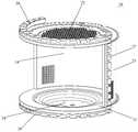
图2示出了根据本发明的实施例的加热烹调器的闭合状态图;Fig. 2 shows a closed state diagram of the heating cooker according to the embodiment of the present invention;
图3示出了根据本发明的实施例的加热烹调器的打开状态图;FIG. 3 shows an open state diagram of the heating cooker according to the embodiment of the present invention;
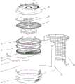
图4示出了根据本发明的实施例的加热烹调器的分解结构图;4 shows an exploded structural view of a heating cooker according to an embodiment of the present invention;
图5示出了根据本发明的实施例的腔体的结构图;FIG. 5 shows a structural diagram of a cavity according to an embodiment of the present invention;
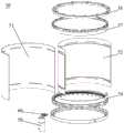
图6示出了根据本发明的实施例的腔体的分解结构图;FIG. 6 shows an exploded structural view of a cavity according to an embodiment of the present invention;
图7示出了根据本发明的实施例的门体及导轨结构的结构图;7 shows a structural diagram of a door body and a guide rail structure according to an embodiment of the present invention;
图8示出了根据本发明的实施例的门体及导轨结构的分解结构图;8 shows an exploded structural view of the door body and the guide rail structure according to an embodiment of the present invention;
图9示出了根据本发明的实施例的上侧可动导轨和上侧固定导轨的结构图;FIG. 9 shows a structural diagram of an upper movable guide rail and an upper fixed guide rail according to an embodiment of the present invention;
图10示出了根据本发明的实施例的上电器室的分解结构图;10 shows an exploded structural view of an upper electrical room according to an embodiment of the present invention;
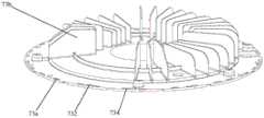
图11示出了根据本发明的实施例的顶部导风板的结构图;Figure 11 shows a structural diagram of a top air deflector according to an embodiment of the present invention;
图12示出了根据本发明的实施例的顶部支撑板的部分结构图;12 shows a partial structural view of a top support plate according to an embodiment of the present invention;
图2至图12中附图标记与部件名称之间的对应关系为:The corresponding relationship between the reference numerals and the component names in Fig. 2 to Fig. 12 is:
10底座,20腔体,21底壁,22顶壁,23后壁,24搅拌腔,25搅拌腔盖板,26左侧扼流齿,27右侧扼流齿,28上侧扼流齿,29下侧扼流齿,30加强件,32后支撑板,33后侧外罩,34加热腔,50门体,50a门面,51外透视层,52内透视层,54下侧可动导轨,57上侧可动导轨,57a第四风道,572第二凸起部,58上侧固定导轨,58a第三风道,59门体驱动电机,60门体驱动齿轮,70上盖,71顶部装饰片,72顶部支撑板,72a第二风道,722定位柱,724导向孔,73顶部导风板,73a第一风道,73b导风片,732定位孔,734连接孔,74风扇,75扬声器,76语音功能模块,77投影器,78投影电源电路,80发热管。10 base, 20 cavity, 21 bottom wall, 22 top wall, 23 rear wall, 24 mixing chamber, 25 mixing chamber cover, 26 left choke teeth, 27 right choke teeth, 28 upper choke teeth, 29 lower choke teeth, 30 reinforcement, 32 rear support plate, 33 rear housing, 34 heating chamber, 50 door body, 50a door face, 51 outer perspective layer, 52 inner perspective layer, 54 lower movable guide rail, 57 Upper movable guide rail, 57a fourth air duct, 572 second protrusion, 58 upper fixed guide rail, 58a third air duct, 59 door drive motor, 60 door drive gear, 70 upper cover, 71 top decoration sheet, 72 top support plate, 72a second air duct, 722 positioning post, 724 guide hole, 73 top air guide plate, 73a first air duct, 73b air guide sheet, 732 positioning hole, 734 connecting hole, 74 fan, 75 Speakers, 76 voice function modules, 77 projectors, 78 projection power circuits, 80 heating tubes.
具体实施方式Detailed ways
为了能够更清楚地理解本发明的上述目的、特征和优点,下面结合附图和具体实施方式对本发明进行进一步的详细描述。需要说明的是,在不冲突的情况下,本申请的实施例及实施例中的特征可以相互组合。In order to understand the above objects, features and advantages of the present invention more clearly, the present invention will be further described in detail below with reference to the accompanying drawings and specific embodiments. It should be noted that the embodiments of the present application and the features in the embodiments may be combined with each other in the case of no conflict.
在下面的描述中阐述了很多具体细节以便于充分理解本发明,但是,本发明还可以采用其他不同于在此描述的其他方式来实施,因此,本发明的保护范围并不限于下面公开的具体实施例的限制。Many specific details are set forth in the following description to facilitate a full understanding of the present invention. However, the present invention can also be implemented in other ways different from those described herein. Therefore, the protection scope of the present invention is not limited to the specific details disclosed below. Example limitations.
如图2至图12所示,其中,图2为本发明实施例所涉及的加热烹调器的示意图。图3为门体50打开状态下的立体图。如图2及图3所示,加热烹调器主要具备底座10,其内部可形成供电源板、磁控管、变频器等电器件安装的下电器室(未图示);腔体20,其设置于底座10,内部形成有供食物放置的加热腔34,加热腔34的一侧形成为供食物进出的开口;门体50,其设置于腔体20上,用于封闭或打开加热腔34的开口;上盖70,其盖设于腔体20之上,内部可形成供风扇、语音控制模块等电器件安装的上电器室(未图示)。As shown in FIGS. 2 to 12 , wherein, FIG. 2 is a schematic diagram of the heating cooker according to the embodiment of the present invention. FIG. 3 is a perspective view of the
具体地,如图4及图7至图12所示,下电器室和/或上电器室相对门体50的外表面形成导风风道;下电器室或上电器室中设置有风扇74,风扇74通过导风风道从下电器室或上电器室向门体50的外表面吹风,或者风扇74通过导风风道从门体50的外表面向下电器室或上电器室引风。Specifically, as shown in FIG. 4 and FIG. 7 to FIG. 12 , the lower electrical room and/or the upper electrical room form an air guide duct relative to the outer surface of the
在该实施例中,风扇74吹出的风沿导风风道流向门体50的外表面;或者将门体50的外表面的高温气流从导风风道引出,以使门体50可以快速冷却,不需要将门体的厚度设置的过厚就可防止用户接触门体50时被烫伤,同时不会影响门体50观察腔体20内部时的可视性。In this embodiment, the wind blown by the
在上述实施例中,优选地,如图4和图10所示,风扇74设置于上电器室;上电器室中设置有圆盘状的顶部导风板73,风扇74设置于顶部导风板73上,风扇74发出的风由顶部导风板73引导到导风风道。In the above embodiment, preferably, as shown in FIG. 4 and FIG. 10 , the
在该实施例中,通过顶部导风板73的导向作用,将风扇74吹出的风由顶部导风板73的中央向边缘流动,或者由顶部导风板73的边缘向中央流动;同时在风扇74的驱动作用下,以提高气流流动速度,使得电器件以及门体50可以快速冷却,提高冷却效率。In this embodiment, through the guiding action of the
进一步地,如图4、图10和图11所示,所示,风扇74设置于顶部导风板73中央,顶部导风板73的上表面设置由中心向圆周方向延伸的导风片73b。Further, as shown in FIG. 4 , FIG. 10 and FIG. 11 , the
在该实施例中,通过导风片73b形成顶部导风板73的中央与边缘之间的气体流动路径,实现顶部导风板73的导向作用。In this embodiment, the air flow path between the center and the edge of the top
在本发明的一些实施例中,如图11所示,顶部导风板73的边缘设置有第一风道73a;第一风道73a构成导风风道的至少一部分。In some embodiments of the present invention, as shown in FIG. 11 , the edge of the top
在该实施例中,在风扇74的驱动作用下,门体50表面的高温气流通过位于顶部导风板73边缘处的第一风道73a排出;或者风扇74吹出的风从顶部导风板73边缘处的第一风道73a吹向门体50,以使门体可以快速冷却,提高加热烹调器的散热效率。In this embodiment, under the driving action of the
在本发明的另一些实施例中,如图4、图10和图12所示,加热烹调器还包括设有凸缘的圆筒状的顶部支撑板72,顶部支撑板72支撑于腔体20之上,顶部导风板73支撑于顶部支撑板72之上,顶部支撑板72的凸缘处与顶部导风板73的第一风道73a对应的位置设置有第二风道72a;第一风道73a与第二风道72a构成导风风道的至少一部分。In other embodiments of the present invention, as shown in FIG. 4 , FIG. 10 and FIG. 12 , the heating cooker further includes a cylindrical
在该实施例中,通过相配合的第一风道73a和第二风道72a,形成用于气流流通的导风风道,将风扇74吹出的风沿第一风道73a和第二风道72a吹向炉门,以使门体50可以快速冷却,不需要将门体的厚度设置的过厚就可防止用户接触门体50时被烫伤,同时不会影响门体50观察腔体20内部时的可视性。In this embodiment, the
图7为本发明实施例所涉及的门体50及其关联结构的组装图。图8为本发明实施例所涉及的门体50及其关联结构的分解示意图。如图7及图8所示,门体50主要包括:形成为大致半圆筒形的外透视层51;与该外透视层51适配的、同样形成为大致半圆筒形的内透视层52;配置于外透视层51与内透视层52之间的、同样形成为大致半圆筒形的金属网孔层,其表面上形成众多通孔以防止微波加热功能下微波由加热腔34通过外透视层51与内透视层52透射出来,其与外透视层51、内透视层52这两者构成门面50a;形成为大致圆环状的上侧可动导轨57,其用于从上侧固定上述门面50a;上侧固定导轨58,其形成为与上侧可动导轨57适配的环状,用于从上侧和/或外侧支撑上侧可动导轨57,且上侧可动导轨57可相对上侧固定导轨58滑动或通过两者之间设置的多个辊轮(未图示)滚动。FIG. 7 is an assembly diagram of the
需要说明的是,在图中,由于金属网孔层与外透视层51、内透视层52紧密贴合,在图中并未具体示出其结构。It should be noted that, in the figure, since the metal mesh layer is closely attached to the outer see-through
具体地,如图9所示,上侧固定导轨58上设置有第三风道58a;上侧固定导轨58套设于顶部支撑板72外侧,且上侧固定导轨58上的第三风道58a与顶部支撑板72的凸缘处的第二风道72a至少部分正对;第一风道73a、第二风道72a及第三风道58a构成导风风道的至少一部分。Specifically, as shown in FIG. 9 , the upper fixed
在该实施例中,风扇74吹出的风依次沿第一风道73a、第二风道72a及第三风道58a吹向门体50,实现门体50的快速冷却;另外,将第三风道58a设于上侧固定导轨58上,还可实现将上侧固定导轨58和上侧可动导轨57相对转动而产生热量同时排出或冷空气对导轨进行冷却,解决了导轨结构的散热问题。In this embodiment, the wind blown by the
进一步地,上侧可动导轨57上设有第四风道57a,第一风道73a、第二风道72a、第三风道58a及第四风道57a构成导风风道的至少一部分。Further, the upper
在该实施例中,通过第四风道57a,将风扇74吹出的风的一部分导向门体50,另一部分导向腔体,既实现了门体50的快速冷却,又实现了腔体20的快速冷却。In this embodiment, through the
在上述任一实施例中,优选地,如图9所示,上侧可动导轨57上间隔设置多个第二凸起部572,相邻两个第二凸起部572之间的间隙形成第四风道57a。In any of the above embodiments, preferably, as shown in FIG. 9 , a plurality of
在实施例中,通过在上侧可动导轨57上间隔设置多个第二凸起部572,一方面减少两个导轨之间的接触面积,即减小接触面的滑动摩擦阻力,使得两个导轨的相对转动更加顺畅,同时减少两个导轨直接接触产生磨损;另一方面,利用相邻两个第二凸起部572之间的间隙形成用于空气流通的第四风道57a,结构更加简单、降低生产成本。In the embodiment, by arranging a plurality of
需要说明的是,第二凸起部572可以为设置在上侧可动导轨57表面的凸块或凸条,也可以是凸块和凸条的任意组合。It should be noted that, the second protruding
图5为本发明实施例所涉及的腔体20及其关联结构的组装图。图6为本发明实施例所涉及的腔体20及其关联结构的分解示意图。如图5及图6所示,腔体20主要包括:围成加热腔34的底壁21、顶壁22及后壁23;与后壁23重合且分隔而设置的、用于支撑顶壁22等部件的后支撑板32以及盖设于后支撑板32外侧的后侧外罩33。对应于上述底座10可为圆形、类圆形或圆角矩形等形状的底座10,腔体20可为圆柱形、类圆柱形或横截面为圆角矩形的柱体等形状,在本实施例中以腔体20是圆柱形为例进行说明。FIG. 5 is an assembly diagram of the
在本实施例中,底壁21呈圆形板状,且其中央部分向底座10侧下凹而形成搅拌腔24。搅拌腔24通过搅拌腔盖板25相对加热腔34隔开。搅拌腔盖板25由可透过微波的材质形成。后壁23呈大致半圆的弧形,沿底壁21的外周而设置,顶壁22同样为圆形板状,其外周与后壁23连接,由此,底壁21、顶壁22及后壁23形成为前侧(用户操作加热烹调器时面对的一侧)开口而后侧封闭的加热腔34,该开口可由门体50封闭或打开。In this embodiment, the
对于具有微波加热功能的加热烹调器,即使门体50封闭了加热腔34的开口,微波仍可能由门体50与腔体20之间的缝隙泄露出来,为此,在本实施例中,在后壁23的左右两个边缘处分别竖直设置左侧扼流齿26及右侧扼流齿27,在顶壁22的开口侧外周上方设置大致半环形的上侧扼流齿28,在底壁21的开口侧外周下方设置大致半环形的下侧扼流齿29。For the heating cooker with microwave heating function, even if the
后支撑板32呈大致半圆的弧形,设置于后侧,即开口侧的相反侧。相对于后侧,由于前侧不存在后支撑板32支撑等原因,前侧的底壁21部分及下侧扼流齿29容易受重物(如待加热的食物等)等挤压而变形,为此,在本实施例中,在前侧的底壁21部分及下侧扼流齿29下方增设加强件30以提高该部分的强度。The
此外,可选地,如图8所示,还可在底座10上设置门体驱动电机59,其上端设置门体驱动齿轮60,门体驱动齿轮60可与下侧可动导轨54的环状内侧面上形成的齿啮合,这样一来,门体50可在门体驱动电机59的驱动下自动旋转。In addition, optionally, as shown in FIG. 8 , a door body drive
图4为上盖70、发热管80相对其他部件的位置示意图。图10为本发明实施例所涉及的上盖70及部分内部结构的分解示意图。如图4及图10所示,上盖70大致圆盘形状,形成为加热烹调器的顶部。上盖70可与半环状的顶部装饰片71配合,扣设在腔体20。在上盖70与腔体20形成的上电器室内部,设置存在凸缘的圆筒状的顶部支撑板72,其与前述的上侧固定导轨58固定连接。在顶部支撑板72的凸缘面上方,可设置圆盘状的顶部导风板73。顶部导风板73用于将上电器室分成下侧的高温电器室与上侧的低温电器室。高温电器室用于供图4所示发热管80及其关联部件安装,为高温区域。低温电器室用于供顶部风扇74、扬声器75、语音功能模块76、投影器77、投影电源电路78等部件安装,为低温区域。其中,顶部风扇74用于对低温电器室等进行冷却,还可向发热管80吹风,以使得发热管80产生的热量更好地进入加热腔34。FIG. 4 is a schematic diagram showing the positions of the
在上述任一实施例中,优选地,如图11和图12所示,还包括至少一组定位组件,每组定位组件包括相互配合的定位柱722和定位孔732,定位柱722和定位孔732中的一个设于顶部支撑板72上,另一个设于顶部导风板73上。In any of the above-mentioned embodiments, preferably, as shown in FIG. 11 and FIG. 12 , at least one group of positioning components is further included, and each group of positioning components includes a positioning column 722 and a
在该实施例中,在对烹调器的顶部支撑板72和顶部导风板73进行连接时,首先通过定位组件中的定位柱722和定位孔732实现顶部导风板73在顶部支撑板72上的安装位置的确定,通过定位柱722和定位孔732的设置可以实现安装位置的精确定位,便于顶部导风板73的快速安装。In this embodiment, when connecting the
在上述任一实施例中,优选地,如图11和图12所示,还包括至少一组连接组件,每组连接组件包括相互配合的导向孔724和连接孔734,导向孔724和连接孔734中的一个设于顶部支撑板72上,另一个设于顶部导风板73上。In any of the above embodiments, preferably, as shown in FIG. 11 and FIG. 12 , at least one group of connecting components is further included, and each group of connecting components includes a guide hole 724 and a connecting
在该实施例中,通过连接组件中的导向孔724和连接孔734实现对于顶部支撑板72和顶部导风板73的紧固连接;当定位柱722与定位孔732配合且导向孔724与连接孔734相连时,顶部导风板73准确安装在顶部支撑板72上,实现了顶部支撑板72与顶部导风板73的固定连接。In this embodiment, the
在本发明中,术语“第一”、“第二”、“第三”仅用于描述的目的,而不能理解为指示或暗示相对重要性;术语“多个”则指两个或两个以上,除非另有明确的限定。术语“安装”、“相连”、“连接”、“固定”等术语均应做广义理解,例如,“连接”可以是固定连接,也可以是可拆卸连接,或一体地连接;“相连”可以是直接相连,也可以通过中间媒介间接相连。对于本领域的普通技术人员而言,可以根据具体情况理解上述术语在本发明中的具体含义。In the present invention, the terms "first", "second" and "third" are only used for the purpose of description, and cannot be construed as indicating or implying relative importance; the term "multiple" refers to two or two above, unless otherwise expressly defined. The terms "installed", "connected", "connected", "fixed" and other terms should be understood in a broad sense. For example, "connected" can be a fixed connection, a detachable connection, or an integral connection; "connected" can be It is directly connected or indirectly connected through an intermediary. For those of ordinary skill in the art, the specific meanings of the above terms in the present invention can be understood according to specific situations.
本发明的描述中,需要理解的是,术语“上”、“下”、“左”、“右”、“前”、“后”等指示的方位或位置关系为基于附图所示的方位或位置关系,仅是为了便于描述本发明和简化描述,而不是指示或暗示所指的装置或单元必须具有特定的方向、以特定的方位构造和操作,因此,不能理解为对本发明的限制。In the description of the present invention, it should be understood that the orientations or positional relationships indicated by the terms "upper", "lower", "left", "right", "front", "rear", etc. are based on the orientations shown in the accompanying drawings Or the positional relationship is only for the convenience of describing the present invention and simplifying the description, rather than indicating or implying that the referred device or unit must have a specific direction, be constructed and operated in a specific orientation, and therefore should not be construed as a limitation of the present invention.
在本说明书的描述中,术语“一个实施例”、“一些实施例”、“具体实施例”等的描述意指结合该实施例或示例描述的具体特征、结构、材料或特点包含于本发明的至少一个实施例或示例中。在本说明书中,对上述术语的示意性表述不一定指的是相同的实施或实例。而且,描述的具体特征、结构、材料或特点可以在任何的一个或多个实施例或示例中以合适的方式结合。In the description of this specification, the description of the terms "one embodiment", "some embodiments", "specific embodiment", etc. means that a particular feature, structure, material or characteristic described in connection with the embodiment or example is included in the present invention at least one embodiment or example of . In this specification, schematic representations of the above terms do not necessarily refer to the same implementation or example. Furthermore, the particular features, structures, materials or characteristics described may be combined in any suitable manner in any one or more embodiments or examples.
以上仅为本发明的优选实施例而已,并不用于限制本发明,对于本领域的技术人员来说,本发明可以有各种更改和变化。凡在本发明的精神和原则之内,所作的任何修改、等同替换、改进等,均应包含在本发明的保护范围之内。The above are only preferred embodiments of the present invention, and are not intended to limit the present invention. For those skilled in the art, the present invention may have various modifications and changes. Any modification, equivalent replacement, improvement, etc. made within the spirit and principle of the present invention shall be included within the protection scope of the present invention.
Claims (9)
- A heating cooker of the type , comprising:a base (10) having a lower electric chamber formed therein;a cavity (20) which is arranged on the base (10), wherein a heating cavity (34) for placing food is formed inside the cavity, and an side of the heating cavity (34) is formed into an opening for the food to enter and exit;a body (50) disposed on the cavity (20) for closing or opening the opening;the upper cover (70) is arranged on the cavity (20) in a covering mode, and an upper electric appliance chamber is defined between the upper cover (70) and the cavity (20);the lower electric appliance chamber and/or the upper electric appliance chamber form an air guide duct relative to the outer surface of the body (50);a fan (74) is arranged in the lower electric appliance chamber or the upper electric appliance chamber, the fan (74) blows air from the lower electric appliance chamber or the upper electric appliance chamber to the outer surface of the body (50) through the air guide duct, or the fan (74) draws air from the outer surface of the body (50) to the lower electric appliance chamber or the upper electric appliance chamber through the air guide duct;the fan (74) is arranged in the upper electric appliance chamber;the upper electric appliance chamber is internally provided with a disc-shaped top air deflector (73), the fan (74) is arranged on the top air deflector (73), and air blown out by the fan (74) is guided to the air guide duct by the top air deflector (73).
- 2. The heating cooker according to claim 1,the fan (74) is arranged in the center of the top air deflector (73), and an air guiding sheet (73b) extending from the center to the circumferential direction is arranged on the upper surface of the top air deflector (73).
- 3. The heating cooker according to claim 1,the edge of the top air deflector (73) is provided with an th air duct (73 a);the th air duct (73a) constitutes at least part of the air guide duct.
- 4. The heating cooker according to claim 3,the heating cooker also comprises a cylindrical top supporting plate (72) provided with a flange, the top supporting plate (72) is supported above the cavity (20), the top air deflector (73) is supported above the top supporting plate (72), and a second air duct (72a) is arranged at the position, corresponding to the air duct (73a) of the top air deflector (73), of the flange of the top supporting plate (72);the th air duct (73a) and the second air duct (72a) form at least part of the air guide duct.
- 5. The heating cooker according to claim 4, characterized in that said body (50) comprises:an outer see-through layer (51) formed in a semi-cylindrical shape;an inner see-through layer (52) formed in a semi-cylindrical shape fitted to the outer see-through layer (51);a metal mesh layer formed in a semi-cylindrical shape disposed between the outer see-through layer (51) and the inner see-through layer (52), on the surface of which a plurality of through holes are formed;the outer see-through layer (51), the inner see-through layer (52) and the metal mesh layer constitute an face (50 a);an upper movable guide (57) formed in an annular shape for fixing the surface (50a) from above;an upper fixed rail (58) formed in a ring shape fitted to the upper movable rail (57) for supporting the upper movable rail (57) from the upper side and/or the outside, the upper movable rail (57) being movable relative to the upper fixed rail (58);a third air duct (58a) is arranged on the upper fixed guide rail (58);the upper fixed guide rail (58) is sleeved outside the top support plate (72), and the third air duct (58a) on the upper fixed guide rail (58) is at least partially opposite to the second air duct (72a) at the flange of the top support plate (72);the th air duct (73a), the second air duct (72a) and the third air duct (58a) constitute at least parts of the air guide duct.
- 6. The cooking device according to claim 5, wherein a fourth air duct (57a) is provided on the upper movable rail (57), and the th air duct (73a), the second air duct (72a), the third air duct (58a), and the fourth air duct (57a) constitute at least part of the air guide duct.
- 7. The heating cooker according to claim 6, wherein a plurality of second protrusions (572) are provided at intervals on the upper movable rail (57), and a gap between two adjacent second protrusions (572) forms the fourth air duct (57 a).
- 8. The heating cooker according to , further comprising at least sets of positioning elements, each set of positioning elements comprising cooperating positioning posts (722) and positioning holes (732), wherein of the positioning posts (722) and the positioning holes (732) are disposed on the top support plate (72), and of the positioning posts (722) and the positioning holes (732) are disposed on the top air deflector (73).
- 9. The heating cooker according to , further comprising at least sets of connecting members, each set of connecting members comprising a guiding hole (724) and a connecting hole (734) which are matched with each other, wherein of the guiding holes (724) and the connecting holes (734) are provided on the top supporting plate (72), and are provided on the top wind deflector (73).
Priority Applications (2)
| Application Number | Priority Date | Filing Date | Title |
|---|---|---|---|
| CN201810130673.7ACN108266764B (en) | 2018-02-08 | 2018-02-08 | heating cooker |
| PCT/CN2018/083780WO2019153512A1 (en) | 2018-02-08 | 2018-04-19 | Heating cooker |
Applications Claiming Priority (1)
| Application Number | Priority Date | Filing Date | Title |
|---|---|---|---|
| CN201810130673.7ACN108266764B (en) | 2018-02-08 | 2018-02-08 | heating cooker |
Publications (2)
| Publication Number | Publication Date |
|---|---|
| CN108266764A CN108266764A (en) | 2018-07-10 |
| CN108266764Btrue CN108266764B (en) | 2020-01-31 |
Family
ID=62773998
Family Applications (1)
| Application Number | Title | Priority Date | Filing Date |
|---|---|---|---|
| CN201810130673.7AActiveCN108266764B (en) | 2018-02-08 | 2018-02-08 | heating cooker |
Country Status (2)
| Country | Link |
|---|---|
| CN (1) | CN108266764B (en) |
| WO (1) | WO2019153512A1 (en) |
Families Citing this family (8)
| Publication number | Priority date | Publication date | Assignee | Title |
|---|---|---|---|---|
| WO2019032876A1 (en) | 2017-08-09 | 2019-02-14 | Sharkninja Operating Llc | Cooking device and components thereof |
| CN108266763A (en)* | 2018-02-08 | 2018-07-10 | 广东美的厨房电器制造有限公司 | Heating device |
| US11051654B2 (en) | 2019-02-25 | 2021-07-06 | Sharkninja Operating Llc | Cooking device and components thereof |
| WO2020176477A1 (en) | 2019-02-25 | 2020-09-03 | Sharkninja Operating Llc | Cooking system with guard |
| US20220408966A1 (en) | 2019-07-15 | 2022-12-29 | Sharkninja Operating Llc | Cooking device and components thereof |
| US11678765B2 (en) | 2020-03-30 | 2023-06-20 | Sharkninja Operating Llc | Cooking device and components thereof |
| US12137838B2 (en) | 2020-12-30 | 2024-11-12 | Sharkninja Operating Llc | Cooking device and components thereof |
| US11882961B1 (en) | 2023-01-18 | 2024-01-30 | Sharkninja Operating Llc | Cover plate for cooking devices |
Citations (5)
| Publication number | Priority date | Publication date | Assignee | Title |
|---|---|---|---|---|
| CN2300827Y (en)* | 1997-08-01 | 1998-12-16 | 张小虎 | Safety microwave oven |
| EP2469178A1 (en)* | 2010-12-23 | 2012-06-27 | BSH Bosch und Siemens Hausgeräte GmbH | Cooking oven |
| CN203693261U (en)* | 2013-01-15 | 2014-07-09 | 夏普株式会社 | Heating cooker |
| CN205939292U (en)* | 2016-08-01 | 2017-02-08 | 广东美的厨房电器制造有限公司 | Microwave cooking utensil |
| CN206560362U (en)* | 2016-11-08 | 2017-10-17 | 九阳股份有限公司 | A kind of air fryer using safety |
Family Cites Families (7)
| Publication number | Priority date | Publication date | Assignee | Title |
|---|---|---|---|---|
| US7874289B2 (en)* | 2005-03-29 | 2011-01-25 | Maytag Corporation | Door assembly for a cooking appliance |
| KR100610670B1 (en)* | 2005-05-13 | 2006-08-09 | 삼성전자주식회사 | Heating cooker |
| US7650881B2 (en)* | 2006-11-13 | 2010-01-26 | General Electric Company | Door assembly for a cooking appliance |
| US8141549B2 (en)* | 2008-09-12 | 2012-03-27 | General Electric Company | Appliance with a vacuum-based reverse airflow cooling system using one fan |
| CN203709860U (en)* | 2013-12-17 | 2014-07-16 | 广东美的厨房电器制造有限公司 | Dual-air duct radiating system of oven and electric oven |
| CN106136951A (en)* | 2016-09-20 | 2016-11-23 | 美得彼烹饪设备制造(上海)有限公司 | Compact fast oven |
| CN206324675U (en)* | 2016-09-20 | 2017-07-14 | 美得彼烹饪设备制造(上海)有限公司 | Compact fast oven |
- 2018
- 2018-02-08CNCN201810130673.7Apatent/CN108266764B/enactiveActive
- 2018-04-19WOPCT/CN2018/083780patent/WO2019153512A1/ennot_activeCeased
Patent Citations (5)
| Publication number | Priority date | Publication date | Assignee | Title |
|---|---|---|---|---|
| CN2300827Y (en)* | 1997-08-01 | 1998-12-16 | 张小虎 | Safety microwave oven |
| EP2469178A1 (en)* | 2010-12-23 | 2012-06-27 | BSH Bosch und Siemens Hausgeräte GmbH | Cooking oven |
| CN203693261U (en)* | 2013-01-15 | 2014-07-09 | 夏普株式会社 | Heating cooker |
| CN205939292U (en)* | 2016-08-01 | 2017-02-08 | 广东美的厨房电器制造有限公司 | Microwave cooking utensil |
| CN206560362U (en)* | 2016-11-08 | 2017-10-17 | 九阳股份有限公司 | A kind of air fryer using safety |
Also Published As
| Publication number | Publication date |
|---|---|
| WO2019153512A1 (en) | 2019-08-15 |
| CN108266764A (en) | 2018-07-10 |
Similar Documents
| Publication | Publication Date | Title |
|---|---|---|
| CN108266764B (en) | heating cooker | |
| CN111608546B (en) | household appliances | |
| CN107049056B (en) | electric oven | |
| US10499464B2 (en) | Cooking appliance | |
| US11852347B2 (en) | Cooking appliance having cooling system | |
| CN113633193B (en) | Shell assembly and cooking appliance having same | |
| CN105662171A (en) | Cooking utensil | |
| CN104613512A (en) | Microwave oven | |
| CN213931069U (en) | Door body heat radiation structure of cooking equipment | |
| CN204240427U (en) | Micro-wave oven | |
| WO2017096779A1 (en) | Microwave oven | |
| CN212204637U (en) | cooking appliances | |
| WO2017166457A1 (en) | Cooking appliance | |
| CN205026750U (en) | microwave heating device | |
| CN108131696B (en) | heating cooker | |
| JP2010286121A (en) | Tabletop type cooking device | |
| CN208205095U (en) | Heating device | |
| CN107548180B (en) | Heating cooker | |
| KR20090017299A (en) | Electric oven with air guide in convection cover | |
| CN114601324B (en) | Cooking apparatus | |
| CN221690709U (en) | Hot air circulation electric oven | |
| CN221222774U (en) | Air duct components and integrated stoves | |
| CN108338695B (en) | heating cooker | |
| KR100633174B1 (en) | Electric oven's convection cover | |
| CN205026751U (en) | Microwave heating device |
Legal Events
| Date | Code | Title | Description |
|---|---|---|---|
| PB01 | Publication | ||
| PB01 | Publication | ||
| SE01 | Entry into force of request for substantive examination | ||
| GR01 | Patent grant | ||
| GR01 | Patent grant |