CN1082453A - Filter assemblies - Google Patents
Filter assembliesDownload PDFInfo
- Publication number
- CN1082453A CN1082453ACN93105783ACN93105783ACN1082453ACN 1082453 ACN1082453 ACN 1082453ACN 93105783 ACN93105783 ACN 93105783ACN 93105783 ACN93105783 ACN 93105783ACN 1082453 ACN1082453 ACN 1082453A
- Authority
- CN
- China
- Prior art keywords
- filter
- flushing
- container
- particles
- carrier fluid
- Prior art date
- Legal status (The legal status is an assumption and is not a legal conclusion. Google has not performed a legal analysis and makes no representation as to the accuracy of the status listed.)
- Granted
Links
- 230000000712assemblyEffects0.000titleclaimsdescription8
- 238000000429assemblyMethods0.000titleclaimsdescription8
- 239000002245particleSubstances0.000claimsabstractdescription24
- 238000011010flushing procedureMethods0.000claimsabstractdescription17
- 239000012530fluidSubstances0.000claimsabstractdescription16
- 238000001914filtrationMethods0.000claimsabstractdescription9
- 239000000919ceramicSubstances0.000claimsabstractdescription8
- 238000002485combustion reactionMethods0.000claimsdescription6
- 229910052751metalInorganic materials0.000claimsdescription3
- 239000002184metalSubstances0.000claimsdescription3
- 238000009825accumulationMethods0.000claims1
- 239000007787solidSubstances0.000abstractdescription9
- 239000012141concentrateSubstances0.000abstractdescription3
- 239000007789gasSubstances0.000description13
- 239000003546flue gasSubstances0.000description4
- 239000013618particulate matterSubstances0.000description4
- UGFAIRIUMAVXCW-UHFFFAOYSA-NCarbon monoxideChemical compound[O+]#[C-]UGFAIRIUMAVXCW-UHFFFAOYSA-N0.000description2
- 239000000428dustSubstances0.000description2
- 238000002309gasificationMethods0.000description2
- 239000007788liquidSubstances0.000description2
- 239000000463materialSubstances0.000description2
- 238000000034methodMethods0.000description2
- 238000012986modificationMethods0.000description2
- 230000004048modificationEffects0.000description2
- 239000004925Acrylic resinSubstances0.000description1
- 229920000178Acrylic resinPolymers0.000description1
- 229910000975Carbon steelInorganic materials0.000description1
- 229910045601alloyInorganic materials0.000description1
- 239000000956alloySubstances0.000description1
- 230000015572biosynthetic processEffects0.000description1
- 229910052799carbonInorganic materials0.000description1
- 239000010962carbon steelSubstances0.000description1
- 239000003245coalSubstances0.000description1
- 239000002817coal dustSubstances0.000description1
- 239000012611container materialSubstances0.000description1
- 230000008602contractionEffects0.000description1
- 230000001419dependent effectEffects0.000description1
- 238000010586diagramMethods0.000description1
- 239000012535impuritySubstances0.000description1
- 238000011068loading methodMethods0.000description1
- 150000002739metalsChemical class0.000description1
- 229920003229poly(methyl methacrylate)Polymers0.000description1
- 229920000728polyesterPolymers0.000description1
- 239000004926polymethyl methacrylateSubstances0.000description1
- 238000007665saggingMethods0.000description1
- 239000004071sootSubstances0.000description1
- 239000010935stainless steelSubstances0.000description1
- 229910001220stainless steelInorganic materials0.000description1
- 238000003786synthesis reactionMethods0.000description1
Images
Classifications
- B—PERFORMING OPERATIONS; TRANSPORTING
- B01—PHYSICAL OR CHEMICAL PROCESSES OR APPARATUS IN GENERAL
- B01D—SEPARATION
- B01D46/00—Filters or filtering processes specially modified for separating dispersed particles from gases or vapours
- B01D46/24—Particle separators, e.g. dust precipitators, using rigid hollow filter bodies
- B01D46/2403—Particle separators, e.g. dust precipitators, using rigid hollow filter bodies characterised by the physical shape or structure of the filtering element
- B01D46/2407—Filter candles
- B—PERFORMING OPERATIONS; TRANSPORTING
- B01—PHYSICAL OR CHEMICAL PROCESSES OR APPARATUS IN GENERAL
- B01D—SEPARATION
- B01D46/00—Filters or filtering processes specially modified for separating dispersed particles from gases or vapours
- B01D46/0002—Casings; Housings; Frame constructions
- B01D46/0005—Mounting of filtering elements within casings, housings or frames
- B01D46/0009—Tray-like arrangements of filters in a vessel
- C—CHEMISTRY; METALLURGY
- C10—PETROLEUM, GAS OR COKE INDUSTRIES; TECHNICAL GASES CONTAINING CARBON MONOXIDE; FUELS; LUBRICANTS; PEAT
- C10J—PRODUCTION OF PRODUCER GAS, WATER-GAS, SYNTHESIS GAS FROM SOLID CARBONACEOUS MATERIAL, OR MIXTURES CONTAINING THESE GASES; CARBURETTING AIR OR OTHER GASES
- C10J3/00—Production of combustible gases containing carbon monoxide from solid carbonaceous fuels
- C10J3/72—Other features
- C10J3/82—Gas withdrawal means
- C10J3/84—Gas withdrawal means with means for removing dust or tar from the gas
- C—CHEMISTRY; METALLURGY
- C10—PETROLEUM, GAS OR COKE INDUSTRIES; TECHNICAL GASES CONTAINING CARBON MONOXIDE; FUELS; LUBRICANTS; PEAT
- C10K—PURIFYING OR MODIFYING THE CHEMICAL COMPOSITION OF COMBUSTIBLE GASES CONTAINING CARBON MONOXIDE
- C10K1/00—Purifying combustible gases containing carbon monoxide
- C10K1/02—Dust removal
- C10K1/024—Dust removal by filtration
Landscapes
- Chemical & Material Sciences (AREA)
- Engineering & Computer Science (AREA)
- Combustion & Propulsion (AREA)
- Chemical Kinetics & Catalysis (AREA)
- Oil, Petroleum & Natural Gas (AREA)
- Organic Chemistry (AREA)
- Physics & Mathematics (AREA)
- Geometry (AREA)
- General Chemical & Material Sciences (AREA)
- Filtering Materials (AREA)
- Filtering Of Dispersed Particles In Gases (AREA)
Abstract
Translated fromChineseDescription
Translated fromChinese本发明涉及一种包括若干垂直层叠排列的过滤器组件的装置,该装置用于过滤由例如燃烧过程中产生的运载流体中一定的最小尺寸微粒。The present invention relates to an apparatus comprising a plurality of vertically stacked filter assemblies for filtering certain minimum size particles in a carrier fluid produced, for example, by a combustion process.
尤其是本发明与一高温高压的过滤器装置设计有关,例如应用在煤田的气化时,通过用在温度为100-800℃下的陶瓷过滤棒的过滤,从所产生的混合气体中去除所带的固体微粒诸如煤尘,例如应用在油的气化时,通过用在压力为约60巴下的陶瓷过滤棒的过滤,从所生产的生成气体中去除所带干的煤烟。In particular, the present invention is related to the design of a high-temperature and high-pressure filter device, for example, when used in the gasification of coal fields, by using ceramic filter rods at a temperature of 100-800 ° C to remove all the impurities from the resulting mixed gas. Entrained solid particles such as coal dust are used, for example, in the gasification of oil to remove entrained dry soot from the produced product gas by filtration with ceramic filter rods at a pressure of about 60 bar.
一从燃烧产生的烟道气体中分离微粒物质的已知方法以及其它这类方法都使用了多孔的滤器元件,这些多孔滤器包含有若干由一共用支撑板或经常称为管片所支撑的相互成平行关系的滤管组成。烟通气一般都很热,例如温度在150℃且在大气压力下。在这些条件下,典型的过滤管都由聚酯、丙烯酸树脂或玻璃制成,对加压的流化床燃烧情况下,合成气体的温度高达900℃,气体压力从5个大气压到15个大气压,在这种情况下,过滤管就由多孔陶瓷或刚性的烧结多孔不锈钢材料制成,由不同过滤管所过滤的微粒其大小从0.2微米到20微米不等且其重量的总和为气体重量的千分之十或更大。当在过滤元件所积的尘埃增到2毫米或3毫米厚度时,则压降就稳步上升,那时就要通过抖动过滤管或通过反向气流或借助使用高压脉冲气体流过过滤管来进行清理尘埃。A known method of separating particulate matter from flue gases produced by combustion, as well as other such methods, uses porous filter elements comprising a number of interconnected cells supported by a common support plate or often referred to as a segment. Composed of filter tubes in parallel relationship. The flue gas is generally very hot, for example at a temperature of 150°C and at atmospheric pressure. Under these conditions, typical filter tubes are made of polyester, acrylic resin or glass. In the case of pressurized fluidized bed combustion, the temperature of the synthesis gas is as high as 900 ° C, and the gas pressure is from 5 atmospheres to 15 atmospheres. , in this case, the filter tube is made of porous ceramic or rigid sintered porous stainless steel material, the particles filtered by different filter tubes have a size ranging from 0.2 microns to 20 microns and the sum of their weights is the weight of the gas Ten thousandths or greater. When the dust accumulated in the filter element increases to a thickness of 2 mm or 3 mm, the pressure drop will rise steadily. At that time, it must be carried out by shaking the filter tube or by reverse air flow or by using high-pressure pulsed gas to flow through the filter tube. Clean up the dust.
在设计包含有上述小的单独过滤管组成的任何工业使用过滤组件的困难是在一单一的容器内任何合适和方便地装配这些过滤元件,该单一容器可要求包含成百上千的过滤管且携带微粒的流体(可以是气体或液体)必须以沿着单独的过滤管均匀分布的方式进入该容器。而且各过滤管一定要以上述的任何一种方式或任何一种合适方式进行清理,同时从这些过滤管清理出的微粒物质必须收集起来且最终从容器内清除出去,经过滤的流体必须从容器出来经导管引到一方便的地点。A difficulty in designing any commercially used filter assembly consisting of the aforementioned small individual filter tubes is any suitable and convenient assembly of these filter elements within a single container which may be required to contain hundreds or thousands of filter tubes and The particle-carrying fluid (which can be gas or liquid) must enter this vessel in a manner that is evenly distributed along the individual filter tubes. Moreover, each filter tube must be cleaned in any of the above-mentioned ways or in any suitable way. At the same time, the particulate matter cleaned from these filter tubes must be collected and finally removed from the container. The filtered fluid must be removed from the container Out through the catheter and lead to a convenient location.
上述这些要求都对整个过滤装置的设计和结构,在机械、热力学和空气动力学方面加以诸多限制。The above-mentioned requirements impose many constraints on the design and structure of the entire filter device in terms of mechanics, thermodynamics and aerodynamics.
故而,一典型的采用过滤管的装置包括一含有按上下依附方式支撑过滤管的单一的支撑板或管片的主容器。这种特别类型的装置有不少缺点,首先,唯一办法是通过延伸上述容器内管片的直径支撑更多过滤管。以便来扩大其过滤面积,这就很快导致一实际的机械方面的限止。Thus, a typical apparatus employing filter tubes includes a main vessel containing a single support plate or segment that supports the filter tubes in a dependent up-and-down fashion. This particular type of device has a number of disadvantages, first of all, the only way to support more filter tubes is by extending the diameter of the segment inside the vessel as described above. In order to expand its filter area, this quickly leads to a practical mechanical limitation.
因为管片一般都只在其周边上得到支撑,由于日益增加的重量,管片往往在其中心呈下陷状或者管片必须制成足够厚以防止其中心下陷,这就最终导致经济上不合算,即使高级的合金管片在高温下也不能克服下陷问题,通过设置中心支撑来介决这个下陷问题也行不通,因为由于比较高的温度所产生有关金属不同的膨胀和收缩问题。即便上述下陷问题得到解决,假定这样做经济上也可行,还会有其它与为了容纳更多的过滤管而增大管片尺寸所涉及的缺陷,例如管片尺寸增大时,整个装置形状就变得粗大,最终就会变得不适合驳船,铁路或公路运输。而且当管片尺寸增大时,该主容器本身不仅其直径必须扩大而且厚度也须增加,为了能包容和支撑管片和经受住内压,显然,提供一足够大的容器是很昂贵的,而且也是不经济的。Since segments are generally only supported on their perimeter, segments tend to sag in their centers due to the increased weight or segments must be made thick enough to prevent sagging in the center, which ultimately becomes economically uneconomical , Even high-grade alloy segments cannot overcome the sag problem at high temperatures, and it is not feasible to solve this sag problem by setting a central support, because of the different expansion and contraction problems related to metals due to relatively high temperatures. Even if the aforementioned sag problem were resolved, assuming it was economically feasible to do so, there would be other drawbacks associated with increasing the size of the segment to accommodate more filter tubes, such as the shape of the overall device as the segment increases in size. Get bulky and eventually it becomes unsuitable for barge, rail or road transport. And when the size of the segment increases, not only the diameter of the main container itself must be enlarged but also the thickness must be increased. In order to contain and support the segment and withstand the internal pressure, obviously, it is very expensive to provide a large enough container. And it's not economical either.
而通过增加过滤管的长度也能达到增大上述形式装置的过滤容量,当然这也有自我限制。况且一些颇吸引人的新型高级陶瓷过滤管也是可以买到的,不过其长度不能超过1.5米。And also can reach to increase the filtering capacity of above-mentioned form device by increasing the length of filter tube, certainly this also has self-restriction. Moreover, some attractive new high-grade ceramic filter tubes are also available, but they can not exceed 1.5 meters in length.
这样,为了扩大上述形式过滤装置的过滤容量,由于采用了这些特殊的过滤管就要求扩大管片的直径,因此结果便产生上述的问题。Thus, in order to expand the filtration capacity of the filter apparatus of the above-mentioned type, it is required to enlarge the diameter of the segment due to the use of these special filter tubes, thus resulting in the above-mentioned problems.
此外,应用一将由燃烧或其它较热和较高压环境下产生的烟道气体中的予定最小微粒物质过滤的装置早已公知,上述装置有一限定具有入口装置的内舱的主容器,带有微粒的烟道气(或其它诸如需要过滤的运载流体)能流过该入口装置,以便进入内舱。该容器还包括已过滤的运载流体能通过的单独的出口装置,以便离开内舱。若干过滤器组件设置在容器舱内且相互成间隔关系地支撑以及依靠容器本身并借助一个安置在容器舱内单一的支撑管来支撑,该支撑管最好成垂直方向延伸,用作一支撑过滤器组件的唯一装置,同时该支撑管与这些过滤器组件和容器出口装置相配合可以充当一排出管,以便把已过滤的流体通过出口装置引出此过滤容器。In addition, it is already known to use an apparatus for filtering a predetermined minimum particulate matter from flue gases produced by combustion or other relatively hot and relatively high pressure environments, said apparatus having a main vessel defining an internal compartment having inlet means, with a particulate Flue gas (or other carrier fluid such as that needs to be filtered) can flow through the inlet device in order to enter the internal compartment. The container also includes a separate outlet means through which filtered carrier fluid can pass in order to exit the inner compartment. A plurality of filter assemblies are disposed in the vessel compartment and are supported in spaced relation to each other and are supported by the vessel itself by means of a single support tube disposed within the vessel compartment, preferably extending vertically and serving as a support filter The only means of the filter assembly, while the support tube cooperates with the filter assemblies and the container outlet means to act as a discharge tube to lead the filtered fluid out of the filter container through the outlet means.
然而,上述已知装置仍存在按比率扩大的技术问题,以及相对于大规格外形的面积问题。However, the known devices described above still suffer from the technical problem of scaling up, as well as of the area relative to the large form factor.
此外,也还存在再次夹杂固体微粒的风险从而降低了过滤装置的有效性。Furthermore, there is also the risk of re-entrainment of solid particles reducing the effectiveness of the filter device.
本发明就为了解决这些问题且从避免在下隔层流动的流体中再次夹杂固体微粒并在层叠排列的隔层中提供一固体微粒排出口。The present invention is aimed at solving these problems and avoiding the re-entrainment of solid particles in the fluid flowing in the lower compartment and providing a solid particle discharge port in the stacked compartments.
所以,本发明提供一从由燃烧过程所产生的运载流体中过滤掉一定最小微粒物质的装置。Accordingly, the present invention provides an apparatus for filtering certain minimum particulate matter from a carrier fluid produced by a combustion process.
上述装置包含有:The above devices include:
a)一个设有若干微粒运载流体能通过的入口装置和若干已过滤的运载流体能通过的单独出口装置的细长容器;a) an elongated container having inlet means through which particulate carrier fluid can pass and individual outlet means through which filtered carrier fluid can pass;
b)一微粒能通过且离开容器的出口装置b) an outlet device through which particles can pass and leave the container
c)若干上下间隔开的过滤器组件;c) a number of filter assemblies spaced up and down;
其中上述过滤器组件由装在容器上的管片来承载,这样内舱就成形且Wherein the above-mentioned filter assembly is carried by the segments mounted on the container so that the inner compartment is shaped and
有一上下叠层排列的锥形微粒冲洗系统以集中和聚集颗粒冲洗。There is a cone-shaped particle flushing system arranged in layers up and down to concentrate and gather particles for flushing.
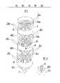
现参照附图并通过实例来更详细叙述本发明,其中图1表示一本发明之叠层的过滤组件的构思设计图Now describe the present invention in more detail with reference to accompanying drawing and by example, wherein Fig. 1 represents the conceptual design diagram of the filtering assembly of a laminate of the present invention
图2表示图1中的细节Figure 2 shows details in Figure 1
现参照图1,一细长容器1有若干脏的气体入口(2a,2b,2c),带有固体微粒的流体经过气体入口并从图中示出已过滤的流体通过“清洁”的气体出口(3a,3b,3c)Referring now to Figure 1, an elongated vessel 1 has a number of dirty gas inlets (2a, 2b, 2c) through which fluid laden with solid particles passes and from which the filtered fluid passes through "clean" gas outlets (3a, 3b, 3c)
容器1包含有若干以任何合适方式支撑的管片(4a,4b,4c),每个管片其用途在于以任何合适方式支撑若干过滤管6,这样就形成了舱隔开的容器The vessel 1 comprises a number of segments (4a, 4b, 4c) supported in any suitable manner, each segment serving to support a number of
最好陶瓷过滤棒用来作为过滤管6。在另外一本发明最佳实施例中,烧结金属棒被用作过滤棒。Preferably ceramic filter rods are used as
与任何进一步加工固体微粒的合适装置连接的微粒排出管7(理由未清楚示明)设置在容器的底部。A particle discharge pipe 7 (for reasons not clearly shown) connected to any suitable means for further processing of the solid particles is provided at the bottom of the vessel.
此外,容器1有一上下叠层排列的锥形微粒冲洗系统以集中和实现微粒冲洗。In addition, the container 1 has a cone-shaped particle flushing system stacked up and down to concentrate and realize particle flushing.
该系统有若干连到管片(4b,4c)和容器壁上的冲洗锥(8a,8b),各管片排入锥部的下方的垂直冲洗管A以机械方式相连。The system has a number of flushing cones (8a, 8b) connected to the segments (4b, 4c) and to the vessel wall, mechanically connected by a vertical flushing pipe A below which the segments discharge into the cones.
最下方的锥体(8c)连到一固体微粒排出管7。The lowermost cone (8c) is connected to a solid
图2更详细示出管片4c连结管A的布置图,管A来自紧邻较高叠层和冲洗锥8b。Figure 2 shows in more detail the arrangement of
在图1,为了清晰的原因只示出了3个管片,3个冲洗锥,3个气体入口和3个气体出口,但是要明白,为了适应本发明目的,可以采用任何数目的管片、冲洗锥,气体入口和气体出口。In Fig. 1, only 3 segments, 3 flushing cones, 3 gas inlets and 3 gas outlets are shown for reasons of clarity, but it is to be understood that any number of segments, Flush cone, gas inlet and gas outlet.
另外还能采用任何合适数目的形状以及材料的过滤器。In addition, any suitable number of filters of shapes and materials can be used.
参照下列设计表格并通过该实例来说明本发明:The invention is illustrated by this example with reference to the following design form:
设计要点Design Points
过滤器介质:陶瓷棒Filter Media: Ceramic Rod
过滤器尺寸:外径6厘米×长度1.5米Filter size:
最大装载密度:1棒/0.125米2管片面积Maximum loading density: 1 rod/0.125 m2segment area
清洁送液高度:0.5米Clean liquid delivery height: 0.5 meters
冲洗锥的锥角:15°(半角,30°全角)Cone angle of flushing cone: 15° (half angle, 30° full angle)
双叠层double stack
元件总数:912Total number of components: 912
管片外径:2.9米Segment outer diameter: 2.9 meters
总容器高度:16.9米Total container height: 16.9 meters
三叠层Tri-Layer
元件总数:912Total number of components: 912
管片外径:2.4米Segment outer diameter: 2.4 meters
总容器高度:22.3米Total container height: 22.3 meters
容器壁厚度container wall thickness
压力:26巴Pressure: 26 bar
温度:约120℃Temperature: about 120°C
容器材料:碳钢Container Material: Carbon Steel
双叠层double stack
容器壁厚:100毫米Container wall thickness: 100mm
容器重量:131吨Container weight: 131 tons
三叠层Tri-Layer
容器壁厚:83毫米Container wall thickness: 83 mm
容器重量:116吨Container weight: 116 tons
从上述的说明可知,本发明的各种修改对任何本领域的技术人员都是显而易见,故这些改型都包括在本权利要求书的保护范围之内。It can be seen from the above description that various modifications of the present invention are obvious to any person skilled in the art, so these modifications are all included in the protection scope of the claims.
Claims (6)
Translated fromChineseApplications Claiming Priority (2)
| Application Number | Priority Date | Filing Date | Title |
|---|---|---|---|
| EP92201425 | 1992-05-18 | ||
| NL92201425.3 | 1992-05-18 |
Publications (2)
| Publication Number | Publication Date |
|---|---|
| CN1082453Atrue CN1082453A (en) | 1994-02-23 |
| CN1033424C CN1033424C (en) | 1996-12-04 |
Family
ID=8210617
Family Applications (1)
| Application Number | Title | Priority Date | Filing Date |
|---|---|---|---|
| CN93105783AExpired - Fee RelatedCN1033424C (en) | 1992-05-18 | 1993-05-18 | filter components |
Country Status (12)
| Country | Link |
|---|---|
| US (1) | US5282877A (en) |
| EP (1) | EP0572063B1 (en) |
| JP (1) | JPH0631123A (en) |
| CN (1) | CN1033424C (en) |
| AU (1) | AU656854B2 (en) |
| CA (1) | CA2095189C (en) |
| DE (1) | DE69304794T2 (en) |
| DK (1) | DK0572063T3 (en) |
| ES (1) | ES2092748T3 (en) |
| SG (1) | SG45277A1 (en) |
| TW (1) | TW227526B (en) |
| ZA (1) | ZA933409B (en) |
Cited By (5)
| Publication number | Priority date | Publication date | Assignee | Title |
|---|---|---|---|---|
| CN101060906B (en)* | 2004-08-05 | 2011-06-08 | 帕克汉尼芬有限公司 | Filter assembly |
| CN103201010A (en)* | 2010-11-10 | 2013-07-10 | Posco公司 | Method and device for removing dust particles from reducing gas |
| CN103657158A (en)* | 2012-09-18 | 2014-03-26 | 中国石油天然气股份有限公司 | Elevation type three-phase separator |
| CN104001383A (en)* | 2014-05-30 | 2014-08-27 | 成都易态科技有限公司 | Gas filter device and gas purifying method utilizing same |
| CN110064261A (en)* | 2019-06-08 | 2019-07-30 | 郭绍华 | It is a kind of processing high humility, high temperature, high-dust flue gas high-precision deduster |
Families Citing this family (10)
| Publication number | Priority date | Publication date | Assignee | Title |
|---|---|---|---|---|
| US5453108A (en)* | 1994-05-18 | 1995-09-26 | A. Ahlstrom Corporation | Apparatus for filtering gases |
| DE19527311A1 (en)* | 1995-07-26 | 1997-01-30 | Lurgi Lentjes Babcock Energie | Method and device for cleaning dust-laden gas |
| US6830734B1 (en)* | 1998-11-06 | 2004-12-14 | Shell Oil Company | Separator apparatus |
| US6733575B1 (en) | 1999-06-18 | 2004-05-11 | N.V. Bekaert S.A. | Hot gas filtration system |
| CA2709152C (en)* | 2009-07-08 | 2018-04-03 | Chad Allen Randal | Recycling and treatment process for produced and used flowback fracturing water |
| KR101238894B1 (en)* | 2010-11-12 | 2013-03-11 | 주식회사 포스코 | Sacrificing nozzle of dust reducing apparatus |
| KR101245319B1 (en)* | 2010-11-10 | 2013-03-19 | 주식회사 포스코 | Method for reducing dust from reducing gas |
| CN102172451B (en)* | 2011-03-31 | 2012-12-26 | 飞潮(无锡)过滤技术有限公司 | Filter for carrying out gas-solid separation on high temperature flue gas |
| CN104785023B (en)* | 2015-03-31 | 2017-05-10 | 陕西美斯林能源科技研究院 | Self-cleaning high-temperature oil gas filter dust-removal process device and method |
| KR102281896B1 (en)* | 2021-03-23 | 2021-07-27 | 김경희 | Multi-type auto trap device |
Family Cites Families (6)
| Publication number | Priority date | Publication date | Assignee | Title |
|---|---|---|---|---|
| US4401446A (en)* | 1981-10-28 | 1983-08-30 | Frances H. Johnson | Method and apparatus for increasing the efficiency of internal collection filter bags |
| US4525184A (en)* | 1983-05-20 | 1985-06-25 | Electric Power Research Institute, Inc. | Vertically tiered particle filtering apparatus |
| DE3408627A1 (en)* | 1984-03-09 | 1985-09-12 | Deutsche Babcock Werke AG, 4200 Oberhausen | DEVICE FOR DEDUSTING HOT GASES |
| US4923487A (en)* | 1988-10-17 | 1990-05-08 | The Duriron Company, Inc. | Cross flow diesel particulate trap |
| US5037461A (en)* | 1989-09-25 | 1991-08-06 | Industrial Filter & Pump Mfg. Co. | Filtration apparatus |
| US5143530A (en)* | 1990-10-22 | 1992-09-01 | Westinghouse Electric Corp. | Filtering apparatus |
- 1993
- 1993-04-24TWTW082103166Apatent/TW227526B/zhactive
- 1993-04-29CACA002095189Apatent/CA2095189C/ennot_activeExpired - Fee Related
- 1993-05-06AUAU38421/93Apatent/AU656854B2/ennot_activeCeased
- 1993-05-11USUS08/060,775patent/US5282877A/ennot_activeExpired - Lifetime
- 1993-05-14SGSG1996002588Apatent/SG45277A1/enunknown
- 1993-05-14EPEP93201384Apatent/EP0572063B1/ennot_activeExpired - Lifetime
- 1993-05-14DEDE69304794Tpatent/DE69304794T2/ennot_activeExpired - Fee Related
- 1993-05-14DKDK93201384.0Tpatent/DK0572063T3/enactive
- 1993-05-14ESES93201384Tpatent/ES2092748T3/ennot_activeExpired - Lifetime
- 1993-05-17JPJP5136963Apatent/JPH0631123A/enactivePending
- 1993-05-17ZAZA933409Apatent/ZA933409B/enunknown
- 1993-05-18CNCN93105783Apatent/CN1033424C/ennot_activeExpired - Fee Related
Cited By (7)
| Publication number | Priority date | Publication date | Assignee | Title |
|---|---|---|---|---|
| CN101060906B (en)* | 2004-08-05 | 2011-06-08 | 帕克汉尼芬有限公司 | Filter assembly |
| CN103201010A (en)* | 2010-11-10 | 2013-07-10 | Posco公司 | Method and device for removing dust particles from reducing gas |
| CN103657158A (en)* | 2012-09-18 | 2014-03-26 | 中国石油天然气股份有限公司 | Elevation type three-phase separator |
| CN103657158B (en)* | 2012-09-18 | 2015-05-27 | 中国石油天然气股份有限公司 | Elevation type oil-gas-water three-phase separator |
| CN104001383A (en)* | 2014-05-30 | 2014-08-27 | 成都易态科技有限公司 | Gas filter device and gas purifying method utilizing same |
| CN104001383B (en)* | 2014-05-30 | 2016-08-24 | 成都易态科技有限公司 | Gas-filtering device and use the method for gas purification of this device |
| CN110064261A (en)* | 2019-06-08 | 2019-07-30 | 郭绍华 | It is a kind of processing high humility, high temperature, high-dust flue gas high-precision deduster |
Also Published As
| Publication number | Publication date |
|---|---|
| DE69304794D1 (en) | 1996-10-24 |
| EP0572063B1 (en) | 1996-09-18 |
| DE69304794T2 (en) | 1997-02-27 |
| SG45277A1 (en) | 1998-01-16 |
| CA2095189A1 (en) | 1993-11-19 |
| CN1033424C (en) | 1996-12-04 |
| ZA933409B (en) | 1994-11-15 |
| AU656854B2 (en) | 1995-02-16 |
| DK0572063T3 (en) | 1996-10-07 |
| TW227526B (en) | 1994-08-01 |
| US5282877A (en) | 1994-02-01 |
| EP0572063A1 (en) | 1993-12-01 |
| ES2092748T3 (en) | 1996-12-01 |
| JPH0631123A (en) | 1994-02-08 |
| AU3842193A (en) | 1993-11-25 |
| CA2095189C (en) | 2004-04-13 |
Similar Documents
| Publication | Publication Date | Title |
|---|---|---|
| CN1082453A (en) | Filter assemblies | |
| CN1236854C (en) | Filtration and electrostatic deposition device and method for cleaning dust on its filter elements | |
| US4604112A (en) | Electrostatic precipitator with readily cleanable collecting electrode | |
| US4525184A (en) | Vertically tiered particle filtering apparatus | |
| US7314495B2 (en) | Process and device for eliminating the particles contained in a stream of fluid | |
| CN106237751B (en) | A particle bed dust removal catalyst | |
| CA2253519C (en) | Hot gas filter and system assembly | |
| US5474585A (en) | Filtering apparatus | |
| CN1170613C (en) | Apparatus and method for removing solid particles from a gas | |
| EP2411115B1 (en) | Vessel for removing solid particles from gases | |
| CN201333367Y (en) | Complex fly ash filter with cyclone inside for pre dust removal | |
| CN101658750B (en) | Composite fly ash filter with built-in cyclone pre-dedusting | |
| CN1850345A (en) | Gas-solid cyclone separator | |
| EP1169108A1 (en) | Mobile granular bed filtration apparatus for hot gas conditioning | |
| USRE34055E (en) | Vertically tiered particle filtering apparatus | |
| CN114288776B (en) | Device for continuously purifying high-temperature dust-containing gas by using dynamic ceramic membrane | |
| JPH04500034A (en) | fiber bed filtration equipment | |
| CN215692462U (en) | Cloth bag dust collector with air inlet and outlet at same side | |
| CN2805886Y (en) | Combined wall-flow honeycomb ceramic filter dust removal device | |
| CN2392596Y (en) | Deposit flow type multi-tube duster | |
| JP3282273B2 (en) | Ceramic filter | |
| AU705702B2 (en) | Separator apparatus to remove particles from a gas stream | |
| D Sharma | Review of patented technologies for fluid-solid separation relevant to specific industrial applications | |
| CN114425209A (en) | Scale pan and device for trapping solid matter in gas | |
| CN1223599A (en) | Hot gas filter and system assembly |
Legal Events
| Date | Code | Title | Description |
|---|---|---|---|
| C06 | Publication | ||
| PB01 | Publication | ||
| C10 | Entry into substantive examination | ||
| SE01 | Entry into force of request for substantive examination | ||
| C14 | Grant of patent or utility model | ||
| GR01 | Patent grant | ||
| C17 | Cessation of patent right | ||
| CF01 | Termination of patent right due to non-payment of annual fee | Granted publication date:19961204 |