CN108245357B - Mechanical operating table and hybrid operating room system - Google Patents
Mechanical operating table and hybrid operating room systemDownload PDFInfo
- Publication number
- CN108245357B CN108245357BCN201711209764.1ACN201711209764ACN108245357BCN 108245357 BCN108245357 BCN 108245357BCN 201711209764 ACN201711209764 ACN 201711209764ACN 108245357 BCN108245357 BCN 108245357B
- Authority
- CN
- China
- Prior art keywords
- vertical
- joint
- horizontal
- rotation
- joints
- Prior art date
- Legal status (The legal status is an assumption and is not a legal conclusion. Google has not performed a legal analysis and makes no representation as to the accuracy of the status listed.)
- Expired - Fee Related
Links
- 239000003638chemical reducing agentSubstances0.000claimsdescription57
- 238000003384imaging methodMethods0.000claimsdescription31
- 238000002595magnetic resonance imagingMethods0.000claimsdescription5
- 238000005096rolling processMethods0.000claimsdescription2
- 238000001514detection methodMethods0.000description17
- 230000000694effectsEffects0.000description6
- 238000001356surgical procedureMethods0.000description6
- 238000010586diagramMethods0.000description5
- 230000002452interceptive effectEffects0.000description4
- 239000000463materialSubstances0.000description4
- 230000005855radiationEffects0.000description3
- XEEYBQQBJWHFJM-UHFFFAOYSA-NIronChemical compound[Fe]XEEYBQQBJWHFJM-UHFFFAOYSA-N0.000description2
- 230000005540biological transmissionEffects0.000description2
- 239000004918carbon fiber reinforced polymerSubstances0.000description2
- 230000005484gravityEffects0.000description2
- 230000001678irradiating effectEffects0.000description2
- 230000001151other effectEffects0.000description2
- 230000002093peripheral effectEffects0.000description2
- 206010002091AnaesthesiaDiseases0.000description1
- OKTJSMMVPCPJKN-UHFFFAOYSA-NCarbonChemical compound[C]OKTJSMMVPCPJKN-UHFFFAOYSA-N0.000description1
- 229910052782aluminiumInorganic materials0.000description1
- XAGFODPZIPBFFR-UHFFFAOYSA-NaluminiumChemical compound[Al]XAGFODPZIPBFFR-UHFFFAOYSA-N0.000description1
- 230000037005anaesthesiaEffects0.000description1
- 239000003575carbonaceous materialSubstances0.000description1
- 239000003814drugSubstances0.000description1
- 229910002804graphiteInorganic materials0.000description1
- 239000010439graphiteSubstances0.000description1
- 229910052742ironInorganic materials0.000description1
- 230000007774longtermEffects0.000description1
- 229910052751metalInorganic materials0.000description1
- 239000002184metalSubstances0.000description1
- 238000000034methodMethods0.000description1
- 238000012986modificationMethods0.000description1
- 230000004048modificationEffects0.000description1
- 238000002834transmittanceMethods0.000description1
Images


Classifications
- A—HUMAN NECESSITIES
- A61—MEDICAL OR VETERINARY SCIENCE; HYGIENE
- A61B—DIAGNOSIS; SURGERY; IDENTIFICATION
- A61B6/00—Apparatus or devices for radiation diagnosis; Apparatus or devices for radiation diagnosis combined with radiation therapy equipment
- A61B6/04—Positioning of patients; Tiltable beds or the like
- A61B6/0407—Supports, e.g. tables or beds, for the body or parts of the body
- A—HUMAN NECESSITIES
- A61—MEDICAL OR VETERINARY SCIENCE; HYGIENE
- A61B—DIAGNOSIS; SURGERY; IDENTIFICATION
- A61B6/00—Apparatus or devices for radiation diagnosis; Apparatus or devices for radiation diagnosis combined with radiation therapy equipment
- A61B6/44—Constructional features of apparatus for radiation diagnosis
- A61B6/4417—Constructional features of apparatus for radiation diagnosis related to combined acquisition of different diagnostic modalities
- A—HUMAN NECESSITIES
- A61—MEDICAL OR VETERINARY SCIENCE; HYGIENE
- A61B—DIAGNOSIS; SURGERY; IDENTIFICATION
- A61B5/00—Measuring for diagnostic purposes; Identification of persons
- A61B5/05—Detecting, measuring or recording for diagnosis by means of electric currents or magnetic fields; Measuring using microwaves or radio waves
- A61B5/055—Detecting, measuring or recording for diagnosis by means of electric currents or magnetic fields; Measuring using microwaves or radio waves involving electronic [EMR] or nuclear [NMR] magnetic resonance, e.g. magnetic resonance imaging
- A—HUMAN NECESSITIES
- A61—MEDICAL OR VETERINARY SCIENCE; HYGIENE
- A61B—DIAGNOSIS; SURGERY; IDENTIFICATION
- A61B5/00—Measuring for diagnostic purposes; Identification of persons
- A61B5/70—Means for positioning the patient in relation to the detecting, measuring or recording means
- A61B5/704—Tables
- A—HUMAN NECESSITIES
- A61—MEDICAL OR VETERINARY SCIENCE; HYGIENE
- A61B—DIAGNOSIS; SURGERY; IDENTIFICATION
- A61B6/00—Apparatus or devices for radiation diagnosis; Apparatus or devices for radiation diagnosis combined with radiation therapy equipment
- A61B6/04—Positioning of patients; Tiltable beds or the like
- A61B6/0487—Motor-assisted positioning
- A—HUMAN NECESSITIES
- A61—MEDICAL OR VETERINARY SCIENCE; HYGIENE
- A61G—TRANSPORT, PERSONAL CONVEYANCES, OR ACCOMMODATION SPECIALLY ADAPTED FOR PATIENTS OR DISABLED PERSONS; OPERATING TABLES OR CHAIRS; CHAIRS FOR DENTISTRY; FUNERAL DEVICES
- A61G13/00—Operating tables; Auxiliary appliances therefor
- A61G13/02—Adjustable operating tables; Controls therefor
- A61G13/04—Adjustable operating tables; Controls therefor tiltable around transverse or longitudinal axis
- A—HUMAN NECESSITIES
- A61—MEDICAL OR VETERINARY SCIENCE; HYGIENE
- A61G—TRANSPORT, PERSONAL CONVEYANCES, OR ACCOMMODATION SPECIALLY ADAPTED FOR PATIENTS OR DISABLED PERSONS; OPERATING TABLES OR CHAIRS; CHAIRS FOR DENTISTRY; FUNERAL DEVICES
- A61G13/00—Operating tables; Auxiliary appliances therefor
- A61G13/02—Adjustable operating tables; Controls therefor
- A61G13/06—Adjustable operating tables; Controls therefor raising or lowering of the whole table surface
- A—HUMAN NECESSITIES
- A61—MEDICAL OR VETERINARY SCIENCE; HYGIENE
- A61G—TRANSPORT, PERSONAL CONVEYANCES, OR ACCOMMODATION SPECIALLY ADAPTED FOR PATIENTS OR DISABLED PERSONS; OPERATING TABLES OR CHAIRS; CHAIRS FOR DENTISTRY; FUNERAL DEVICES
- A61G13/00—Operating tables; Auxiliary appliances therefor
- A61G13/10—Parts, details or accessories
- A61G13/104—Adaptations for table mobility, e.g. arrangement of wheels
- B—PERFORMING OPERATIONS; TRANSPORTING
- B25—HAND TOOLS; PORTABLE POWER-DRIVEN TOOLS; MANIPULATORS
- B25J—MANIPULATORS; CHAMBERS PROVIDED WITH MANIPULATION DEVICES
- B25J9/00—Programme-controlled manipulators
- A—HUMAN NECESSITIES
- A61—MEDICAL OR VETERINARY SCIENCE; HYGIENE
- A61B—DIAGNOSIS; SURGERY; IDENTIFICATION
- A61B6/00—Apparatus or devices for radiation diagnosis; Apparatus or devices for radiation diagnosis combined with radiation therapy equipment
- A61B6/04—Positioning of patients; Tiltable beds or the like
- A61B6/0407—Supports, e.g. tables or beds, for the body or parts of the body
- A61B6/0442—Supports, e.g. tables or beds, for the body or parts of the body made of non-metallic materials
- A—HUMAN NECESSITIES
- A61—MEDICAL OR VETERINARY SCIENCE; HYGIENE
- A61G—TRANSPORT, PERSONAL CONVEYANCES, OR ACCOMMODATION SPECIALLY ADAPTED FOR PATIENTS OR DISABLED PERSONS; OPERATING TABLES OR CHAIRS; CHAIRS FOR DENTISTRY; FUNERAL DEVICES
- A61G2210/00—Devices for specific treatment or diagnosis
- A61G2210/50—Devices for specific treatment or diagnosis for radiography
Landscapes
- Health & Medical Sciences (AREA)
- Life Sciences & Earth Sciences (AREA)
- Engineering & Computer Science (AREA)
- Biomedical Technology (AREA)
- Animal Behavior & Ethology (AREA)
- General Health & Medical Sciences (AREA)
- Public Health (AREA)
- Veterinary Medicine (AREA)
- Medical Informatics (AREA)
- Physics & Mathematics (AREA)
- Surgery (AREA)
- Biophysics (AREA)
- Pathology (AREA)
- Heart & Thoracic Surgery (AREA)
- Molecular Biology (AREA)
- Nuclear Medicine, Radiotherapy & Molecular Imaging (AREA)
- High Energy & Nuclear Physics (AREA)
- Radiology & Medical Imaging (AREA)
- Optics & Photonics (AREA)
- Robotics (AREA)
- Mechanical Engineering (AREA)
- Accommodation For Nursing Or Treatment Tables (AREA)
- Manipulator (AREA)
Abstract
Description
Translated fromChinese技术领域technical field
本发明涉及机械手术台以及混合手术室系统。The present invention relates to mechanical operating tables and hybrid operating room systems.
背景技术Background technique
以往,公知有如下的患者定位组件:利用机械臂使载置有患者的工作台移动,并且相对于用于治疗的辐射线源,对患者的位置进行定位(例如参照专利文献1)。Conventionally, there is known a patient positioning unit that moves a table on which a patient is placed by a robot arm and positions the patient with respect to a radiation source used for treatment (for example, see Patent Document 1).
另外,以往,在手术室中,期待一种如下的手术台:能够抑制载置有患者的工作台与周边设备的干涉,并且能够容易地使载置有患者的工作台移动。于是,可以考虑将上述专利文献1的患者定位组件应用于手术室中的手术台,使用机械臂使载置有患者的工作台移动。由此,与使用脚轮来移动手术台的情况不同,能够抑制载置有患者的工作台与周边设备的干涉,并且能够容易地使载置有患者的工作台移动。In addition, conventionally, in an operating room, an operating table that can easily move the table on which the patient is placed can be easily moved while suppressing interference between the table on which the patient is placed and peripheral equipment. Therefore, it is conceivable to apply the patient positioning assembly of the above-mentioned
在先技术文献prior art literature
专利文献Patent Literature
专利文献1
日本特开2009-131718号公报Japanese Patent Application Laid-Open No. 2009-131718
然而,在上述专利文献1那样的患者定位组件中,是以照射用于治疗的辐射线为目的的,所以不需要考虑多个作业人员在载置有患者的工作台的周围进行长时间作业,一般而言,要使用大型的机械臂。因此,在将专利文献1的机械臂应用于手术台的情况下,手术台周围的空间会变窄,在进行手术时会成为医疗从业人员的妨碍。在使包括多个关节在内的机械臂小型化以避免成为手术的妨碍的情况下,关节的大小也会变小,所以存在关节相对于负载的耐性降低这样的问题。尤其是,存在如下情况:当在载置有具有较大体重的患者的状态下使工作台沿上下方向移动时,施加于使工作台上下移动的垂直关节的力矩负载会变大。因此,存在难以使机械臂小型化以避免成为手术的妨碍这样的问题点。However, in the patient positioning unit as in the above-mentioned
发明内容SUMMARY OF THE INVENTION
本发明提供一种能够确保使载置有进行手术的患者的工作台移动的多关节机械臂的垂直关节相对于负载的耐性,并且能够谋求多关节机械臂的小型化的机械手术台。The present invention provides a mechanical operating table capable of ensuring the resistance of vertical joints of an articulated robot arm to a load for moving a table on which a patient for surgery is placed, and enabling downsizing of the articulated robot arm.
基于本发明的第一方式的机械手术台具备患者载置用的工作台和多关节机械臂,所述多关节机械臂的一方端被固定于地板的基座支承,另一方端对工作台进行支承,多关节机械臂至少包括一个垂直关节,垂直关节的转动轴线被配置在水平方向且与工作台的长边方向大致平行的方向上。A mechanical operating table according to a first aspect of the present invention includes a patient placement table and a multi-joint robot arm, one end of which is supported by a base fixed to a floor, and the other end of which is supported on the table. The support, the multi-joint robot arm includes at least one vertical joint, and the rotation axis of the vertical joint is arranged in the horizontal direction and in a direction substantially parallel to the longitudinal direction of the table.
在基于本发明的第一方式的机械手术台中,如上所述,将多关节机械臂的垂直关节的转动轴线配置在水平方向且与工作台的长边方向大致平行的方向上。在此,在为了抑制多关节机械臂与医疗从业人员、其它装置发生干涉而构成为对工作台的长边方向上的一端附近进行支承的情况下,就从支承位置起到载置有患者的状态下的工作台的重心位置为止的距离而言,工作台的长边方向上的距离比工作台的短边方向上的距离大。其结果是,就多关节机械臂的工作台的支承位置处的力矩而言,与绕工作台的长边方向上的转动轴线转动的力矩相比,绕工作台的短边方向上的转动轴线转动的力矩更大。由此,通过将多关节机械臂的垂直关节的转动轴线配置在水平方向且与工作台的长边方向大致平行的方向上,从而能够抑制在使垂直关节转动的方向上支撑工作台的力矩负载变大。换言之,由于能够在垂直关节的转动轴线的方向上对工作台的长边方向上的力矩负载进行支撑,所以不需要增大驱动垂直关节的驱动机构的输出。另外,不需要为了增大驱动机构的输出转矩而设置较大的减速器。其结果是,能够抑制垂直关节变大。由此,能够确保使载置有进行手术的患者的工作台移动的多关节机械臂的垂直关节相对于负载的耐性,并且能够谋求多关节机械臂的小型化。In the mechanical operating table according to the first aspect of the present invention, as described above, the rotation axes of the vertical joints of the multi-joint robot arm are arranged in the horizontal direction and in a direction substantially parallel to the longitudinal direction of the table. Here, when the multi-joint manipulator is configured to support the vicinity of one end in the longitudinal direction of the table in order to prevent interference with medical practitioners and other devices, the position from the support position to the position where the patient is placed is In terms of the distance to the center of gravity of the table in the state, the distance in the long-side direction of the table is larger than the distance in the short-side direction of the table. As a result, in terms of the moment at the support position of the table of the articulated manipulator, the moment about the rotation axis in the short side direction of the table is compared with the moment of rotation about the rotation axis in the long side direction of the table. The turning torque is greater. In this way, by arranging the rotation axes of the vertical joints of the multi-joint manipulator in the horizontal direction and the direction substantially parallel to the longitudinal direction of the table, it is possible to suppress the moment load supporting the table in the direction in which the vertical joints are rotated. get bigger. In other words, since the moment load in the longitudinal direction of the table can be supported in the direction of the rotation axis of the vertical joint, it is not necessary to increase the output of the drive mechanism for driving the vertical joint. In addition, it is not necessary to provide a large reduction gear in order to increase the output torque of the drive mechanism. As a result, the vertical joint can be suppressed from being enlarged. Thereby, it is possible to ensure the resistance of the vertical joints of the articulated robot arm for moving the table on which the patient undergoing surgery is placed with respect to the load, and to reduce the size of the articulated robot arm.
在基于上述第一方式的机械手术台中,优选的是,多关节机械臂构成为对工作台的长边方向上的一端附近进行支承。若按这种方式构成,则能够在与支承于多关节机械臂的工作台的一端侧相反的一侧的工作台的下方确保空间,所以能够在患者载置用的工作台的周边确保充分的空间。由此,能够抑制多关节机械臂与医疗从业人员、其它装置发生干涉。In the mechanical operating table according to the above-described first aspect, it is preferable that the articulated robot arm is configured to support the vicinity of one end in the longitudinal direction of the table. With this configuration, a space can be secured below the table on the side opposite to the one end side of the table supported by the articulated robot arm, so that sufficient space can be secured around the table for placing the patient. space. As a result, the multi-joint manipulator can be prevented from interfering with medical practitioners and other devices.
在基于上述第一方式的机械手术台中,优选的是,多关节机械臂包括多个垂直关节,多个垂直关节各自的转动轴线被配置在水平方向且与工作台的长边方向大致平行的方向上。若按这种方式构成,则能够确保多个垂直关节相对于负载的耐性,并且能够谋求多个垂直关节的小型化。In the mechanical operating table according to the above-mentioned first aspect, it is preferable that the multi-joint manipulator includes a plurality of vertical joints, and the rotation axes of the plurality of vertical joints are arranged in a horizontal direction and a direction substantially parallel to a longitudinal direction of the table. superior. With this configuration, the resistance of the plurality of vertical joints to loads can be ensured, and the size of the plurality of vertical joints can be reduced.
在基于上述第一方式的机械手术台中,优选的是,多关节机械臂还包括对垂直关节进行驱动的驱动机构,驱动机构包括:马达、以及将马达的旋转减速而进行输出的减速器,垂直关节的转动轴线被配置成与减速器的输出旋转轴线一致。若按这种方式构成,则能够利用减速器增大马达的输出转矩,所以不需要增大马达的输出。另外,由于能够将减速器的输出旋转轴配置在水平方向且与工作台的长边方向大致平行的方向上,所以能够抑制相对于减速器的力矩负载变大。In the mechanical operating table based on the above-mentioned first aspect, preferably, the multi-joint robotic arm further includes a drive mechanism for driving the vertical joints, and the drive mechanism includes a motor and a reducer that decelerates the rotation of the motor and outputs the output. The rotational axis of the joint is configured to coincide with the output rotational axis of the reducer. With this configuration, the output torque of the motor can be increased by the speed reducer, so it is not necessary to increase the output of the motor. In addition, since the output rotating shaft of the speed reducer can be arranged in the horizontal direction and in a direction substantially parallel to the longitudinal direction of the table, it is possible to suppress an increase in the moment load on the speed reducer.
在基于上述第一方式的机械手术台中,优选的是,多关节机械臂还包括对垂直关节进行驱动的驱动机构,驱动机构包括:马达、将马达的旋转减速而进行输出的第一减速器、以及将第一减速器的旋转减速而进行输出的第二减速器,垂直关节的转动轴线被配置成与第二减速器的输出旋转轴线一致。若按这种方式构成,则能够利用第一减速器以及第二减速器在两个阶段进行减速,所以能够有效地增大垂直关节的马达的输出转矩。其结果是,能够减小马达的最大输出,所以能够减小垂直关节的马达。In the mechanical operating table based on the above-mentioned first aspect, it is preferable that the multi-joint manipulator further includes a drive mechanism for driving the vertical joints, and the drive mechanism includes a motor, a first reducer that decelerates the rotation of the motor and outputs, In the second speed reducer that decelerates the rotation of the first speed reducer and outputs the output, the rotation axis of the vertical joint is arranged to coincide with the output rotation axis of the second speed reducer. With this configuration, the first speed reducer and the second speed reducer can be used for deceleration in two stages, so that the output torque of the motor of the vertical joint can be effectively increased. As a result, since the maximum output of the motor can be reduced, the motor of the vertical joint can be reduced.
在基于上述第一方式的机械手术台中,优选的是,多关节机械臂包括:水平多关节组件,所述水平多关节组件具有多个水平关节;以及垂直多关节组件,所述垂直多关节组件具有多个垂直关节,水平多关节组件的一方端支承于基座,另一方端对垂直多关节组件的一方端进行支承,垂直多关节组件的另一方端对工作台进行支承。若按这种方式构成,则在垂直多关节组件与工作台之间,工作台不会在水平方向上旋转,所以能够维持垂直关节的转动轴线的延伸方向与工作台的长边方向的关系不变,使工作台沿上下方向以及水平方向移动。另外,能够利用具有多个水平关节的水平多关节组件,使工作台容易地移动到所期望的水平方向上的位置。另外,能够利用具有多个垂直关节的垂直多关节组件,使工作台容易地移动到所期望的上下方向上的位置。另外,由于能够将多个水平关节集中配置在基座侧,并将多个垂直关节集中配置在工作台侧,所以针对水平方向上的移动,能够由基座侧的多个水平关节的驱动来进行,针对上下方向上的移动,能够由工作台侧的多个垂直关节的驱动来进行。由此,由于不需要一边使水平关节与垂直关节联动,一边分别对水平方向以及铅垂方向上的移动进行驱动,所以与交替地配置垂直关节和水平关节的情况相比,能够抑制多关节机械臂的驱动控制变得复杂。In the mechanical operating table based on the above-mentioned first aspect, preferably, the multi-joint robotic arm includes: a horizontal multi-joint assembly having a plurality of horizontal joints; and a vertical multi-joint assembly, the vertical multi-joint assembly There are multiple vertical joints, one end of the horizontal multi-joint assembly is supported on the base, the other end supports one end of the vertical multi-joint assembly, and the other end of the vertical multi-joint assembly supports the worktable. With this configuration, the table does not rotate in the horizontal direction between the vertical articulation unit and the table, so that the relationship between the extension direction of the rotation axis of the vertical joint and the longitudinal direction of the table can be maintained. change, so that the table moves up and down and horizontally. In addition, the table can be easily moved to a desired position in the horizontal direction by using the horizontal multi-joint assembly having a plurality of horizontal joints. In addition, the table can be easily moved to a desired position in the vertical direction by using the vertical multi-joint assembly having a plurality of vertical joints. In addition, since a plurality of horizontal joints can be collectively arranged on the base side and a plurality of vertical joints can be collectively arranged on the table side, the movement in the horizontal direction can be driven by the plurality of horizontal joints on the base side. The movement in the vertical direction can be performed by driving the plurality of vertical joints on the table side. This eliminates the need to drive the horizontal and vertical movements while interlocking the horizontal joints and the vertical joints. Therefore, it is possible to suppress a multi-joint machine compared to the case where the vertical joints and the horizontal joints are alternately arranged. The drive control of the arm becomes complicated.
在该情况下,优选的是,水平多关节组件具有三个水平关节,垂直多关节组件具有三个垂直关节。若按这种方式构成,则在考虑到要确保将水平多关节组件延伸成最大的情况下的长度时,与设置两个以下的水平关节的情况相比,能够减小关节间的距离,所以在将水平多关节组件折叠并收缩的情况下,能够使其更为紧凑。另外,与设置四个以上的水平关节的情况相比,能够简化装置结构。在考虑到要确保将垂直多关节组件延伸成最大的情况下的长度时,与设置两个以下的垂直关节的情况相比,能够减小关节间的距离,所以在将垂直多关节组件折叠并收缩的情况下,能够使其更为紧凑。另外,与设置四个以上的垂直关节的情况相比,能够简化装置结构。In this case, it is preferable that the horizontal multi-joint assembly has three horizontal joints, and the vertical multi-joint assembly has three vertical joints. With this configuration, the distance between the joints can be reduced compared with the case where two or less horizontal joints are provided when considering the length to ensure the maximum extension of the horizontal multi-joint unit. Therefore, When the horizontal multi-joint assembly is folded and retracted, it can be made more compact. Moreover, compared with the case where four or more horizontal joints are provided, the apparatus structure can be simplified. Considering that the length of the vertical multi-joint unit to be extended to the maximum is ensured, the distance between the joints can be reduced compared with the case where two or less vertical joints are provided. Therefore, when the vertical multi-joint unit is folded and In the case of shrinkage, it can be made more compact. In addition, compared with the case where four or more vertical joints are provided, the device structure can be simplified.
在上述多关节机械臂包括水平多关节组件和垂直多关节组件在内的结构中,优选的是,多关节机械臂构成为:利用至少一个水平关节,使工作台绕铅垂方向上的轴线进行偏摆旋转。若按这种方式构成,则能够利用多关节机械臂的一个以上的水平关节,使工作台容易地进行偏摆旋转并移动到所期望的位置。In the structure of the multi-joint manipulator including the horizontal multi-joint assembly and the vertical multi-joint assembly, preferably, the multi-joint manipulator is configured to use at least one horizontal joint to make the worktable move around the axis in the vertical direction. Yaw rotation. With this configuration, the table can be easily yawed and moved to a desired position by using one or more horizontal joints of the articulated robot arm.
在基于上述第一方式的机械手术台中,优选的是,多关节机械臂构成为:利用至少一个垂直关节,使工作台绕长边方向上的轴线进行滚转转动。若按这种方式构成,则能够利用多关节机械臂的一个以上的垂直关节,使工作台容易地进行滚转转动并移动到所期望的转动角度位置。In the mechanical operating table according to the above-described first aspect, preferably, the multi-joint robotic arm is configured to roll and rotate the table around an axis in the longitudinal direction using at least one vertical joint. With this configuration, the table can be easily rolled and moved to a desired rotational angle position by using one or more vertical joints of the articulated robot arm.
在基于上述第一方式的机械手术台中,优选的是,多关节机械臂包括俯仰转动机构,所述俯仰转动机构对工作台进行支承,并使工作台绕短边方向上的轴线进行俯仰转动,俯仰转动机构具有:第一滚珠丝杠,所述第一滚珠丝杠被配置成轴心沿铅垂方向延伸;第二滚珠丝杠,所述第二滚珠丝杠被配置成轴心沿铅垂方向延伸;第一支承构件,所述第一支承构件借助第一滚珠丝杠在铅垂方向上移动,并对工作台进行支承;以及第二支承构件,所述第二支承构件借助第二滚珠丝杠在铅垂方向上移动,并对工作台进行支承,第一支承构件以及第二支承构件在与工作台的长边方向平行的方向上隔开预定距离地进行配置。若按这种方式构成,则通过使第一滚珠丝杠与第二滚珠丝杠联动地进行驱动,从而能够使工作台容易地进行俯仰转动并移动到所期望的转动角度位置。In the mechanical operating table based on the above-mentioned first aspect, preferably, the multi-joint robotic arm includes a pitch rotation mechanism that supports the table and tilts the table around an axis in the short-side direction, The pitch rotation mechanism includes: a first ball screw arranged such that its axis extends in the vertical direction; and a second ball screw arranged such that its axis extends vertically extending in the direction; a first support member that moves in the vertical direction by the first ball screw and supports the table; and a second support member that is supported by the second ball The lead screw moves in the vertical direction to support the table, and the first support member and the second support member are arranged at a predetermined distance in a direction parallel to the longitudinal direction of the table. With this configuration, the table can be easily tilted and moved to a desired rotational angle position by driving the first ball screw and the second ball screw in conjunction with each other.
在该情况下,优选的是,俯仰转动机构还具有:第一直线导轨,所述第一直线导轨被配置成在与第一滚珠丝杠延伸的方向平行的方向上延伸;以及第二直线导轨,所述第二直线导轨被配置成在与第二滚珠丝杠延伸的方向平行的方向上延伸,第一支承构件能够滑动移动地安装于第一直线导轨,第二支承构件能够滑动移动地安装于第二直线导轨。若按这种方式构成,则能够利用第一直线导轨使第一支承构件精度良好地进行直线移动,并且能够利用第二直线导轨使第二支承构件精度良好地进行直线移动,所以能够使工作台精度良好地进行俯仰转动而移动。In this case, it is preferable that the pitch rotation mechanism further includes: a first linear guide that is arranged to extend in a direction parallel to a direction in which the first ball screw extends; and a second linear guide. A linear guide, the second linear guide is arranged to extend in a direction parallel to the direction in which the second ball screw extends, the first support member is slidably attached to the first linear guide, and the second support member is slidable It is movably mounted on the second linear guide. With this configuration, the first support member can be linearly moved with high precision by the first linear guide, and the second support member can be linearly moved with high precision by the second linear guide, so that the work can be performed. The stage is moved by tilting with high precision.
在基于上述第一方式的机械手术台中,优选的是,多关节机械臂包括俯仰转动机构,所述俯仰转动机构对工作台进行支承,并使工作台绕短边方向上的轴线进行俯仰转动,俯仰转动机构具有俯仰转动支承构件,所述俯仰转动支承构件将工作台的一端支承为能够绕俯仰转动的转动轴线转动。若按这种方式构成,则能够利用俯仰转动支承构件对工作台进行支承,并利用俯仰转动机构,使工作台容易地进行俯仰转动并移动到所期望的转动角度位置。In the mechanical operating table based on the above-mentioned first aspect, preferably, the multi-joint robotic arm includes a pitch rotation mechanism that supports the table and tilts the table around an axis in the short-side direction, The pitch rotation mechanism has a pitch rotation support member that supports one end of the table so as to be rotatable about a rotation axis of the pitch rotation. With this configuration, the table can be supported by the tilt rotation support member, and the table can be easily tilted and moved to a desired rotation angle position by the tilt rotation mechanism.
在上述多关节机械臂包括俯仰转动机构在内的结构中,优选的是,多关节机械臂包括:水平多关节组件,所述水平多关节组件具有多个水平关节;以及垂直多关节组件,所述垂直多关节组件具有多个垂直关节,水平多关节组件的一方端支承于基座,另一方端对垂直多关节组件的一方端进行支承,俯仰转动机构支承于垂直多关节组件的另一方端。若按这种方式构成,则能够将多个水平关节集中配置在基座侧,并将多个垂直关节集中配置在工作台侧,所以针对水平方向上的移动,能够由基座侧的多个水平关节的驱动来进行,针对上下方向上的移动,能够由工作台侧的多个垂直关节的驱动来进行。由此,由于不需要一边使水平关节与垂直关节联动,一边分别对水平方向以及铅垂方向上的移动进行驱动,所以与交替地配置垂直关节和水平关节的情况相比,能够抑制多关节机械臂的驱动控制变得复杂。另外,由于能够将俯仰转动机构设置在垂直多关节组件的工作台侧,所以能够与垂直多关节组件相独立,利用俯仰转动机构使工作台容易地进行俯仰转动而移动。In the structure of the above-mentioned multi-joint mechanical arm including the pitching rotation mechanism, preferably, the multi-joint mechanical arm comprises: a horizontal multi-joint assembly, the horizontal multi-joint assembly has a plurality of horizontal joints; and a vertical multi-joint assembly, so The vertical multi-joint assembly has a plurality of vertical joints, one end of the horizontal multi-joint assembly is supported on the base, the other end supports one end of the vertical multi-joint assembly, and the pitch rotation mechanism is supported on the other end of the vertical multi-joint assembly . With this configuration, a plurality of horizontal joints can be arranged in a concentrated manner on the base side and a plurality of vertical joints can be arranged in a concentrated manner on the table side, so that the movement in the horizontal direction can be performed by a plurality of joints on the base side. The horizontal joints are driven, and the vertical movement can be performed by driving a plurality of vertical joints on the table side. This eliminates the need to drive the horizontal and vertical movements while interlocking the horizontal joints and the vertical joints. Therefore, it is possible to suppress a multi-joint machine compared to the case where the vertical joints and the horizontal joints are alternately arranged. The drive control of the arm becomes complicated. In addition, since the tilt rotation mechanism can be provided on the table side of the vertical articulated unit, the table can be easily tilted and moved by the tilt rotation mechanism independently of the vertical articulated unit.
在基于上述第一方式的机械手术台中,优选的是,工作台包括:X射线透射部、以及对X射线透射部进行支承的支承部,多关节机械臂的另一方端对工作台的一端附近的支承部进行支承。若按这种方式构成,则只要将多关节机械臂配置于支承部侧,在X射线透射部的下方确保充分的空间,就能够在X射线透射部的下方放入用于进行X射线摄像的装置,所以能够对载置于工作台的状态下的患者进行X射线摄像。In the mechanical operating table according to the above-mentioned first aspect, it is preferable that the table includes an X-ray transmissive part and a support part that supports the X-ray transmissive part, and the other end of the multi-joint manipulator is preferably positioned in the vicinity of one end of the table The support part is supported. With this configuration, as long as the articulated manipulator is arranged on the support portion side and a sufficient space is secured below the X-ray transmissive portion, the X-ray imaging device can be placed below the X-ray transmissive portion. Since the device is used, X-ray imaging can be performed on a patient placed on the table.
基于本发明的第二方式的混合手术室系统具备:基于第一方式的机械手术台、以及对患者的X射线投影图像进行摄像的X射线摄像装置和对患者的磁共振图像进行摄像的磁共振成像装置中的至少一方。A hybrid operating room system according to a second aspect of the present invention includes the mechanical operating table based on the first aspect, an X-ray imaging device that captures an X-ray projection image of a patient, and a magnetic resonance imaging device that captures a magnetic resonance image of the patient at least one of the imaging devices.
在基于本发明的第二方式的混合手术室系统中,如上所述,由于能够在机械手术台的患者载置用的工作台的周边确保充分的空间,所以能够将X射线摄像装置或磁共振成像装置容易地配置在工作台的周边的空间。In the hybrid operating room system according to the second aspect of the present invention, as described above, since sufficient space can be secured around the table for placing the patient on the mechanical operating table, the X-ray imaging device or the magnetic resonance imaging device can be used. The imaging device is easily arranged in the space around the table.
根据本发明,能够确保使载置有进行手术的患者的工作台移动的机械臂的垂直关节相对于负载的耐性,并且能够谋求机械臂的小型化。According to the present invention, the vertical joint of the robot arm that moves the table on which the patient undergoing surgery is placed can be secured against load, and the robot arm can be reduced in size.
附图说明Description of drawings
图1是表示具备第一实施方式的机械手术台的混合手术室系统的概略的图。FIG. 1 is a diagram showing an outline of a hybrid operating room system including a mechanical operating table according to the first embodiment.
图2是表示第一实施方式的机械手术台的俯视图。FIG. 2 is a plan view showing the mechanical operating table according to the first embodiment.
图3是表示第一实施方式的机械手术台的多关节机械臂的驱动机构的示意图。3 is a schematic diagram showing a drive mechanism of the articulated robot arm of the mechanical operating table according to the first embodiment.
图4是用于说明第一实施方式的机械手术台的能够摄像的最大范围的侧视图。FIG. 4 is a side view for explaining the maximum range that can be imaged in the mechanical operating table according to the first embodiment.
图5是用于说明第一实施方式的机械手术台的能够摄像的最小范围的侧视图。FIG. 5 is a side view for explaining the minimum range that can be imaged in the mechanical operating table according to the first embodiment.
图6是用于说明第一实施方式的机械手术台的滚转转动的主视图。FIG. 6 is a front view for explaining the rolling rotation of the mechanical operating table according to the first embodiment.
图7是表示第一实施方式的机械手术台的俯仰转动机构的侧视图。FIG. 7 is a side view showing a tilting mechanism of the mechanical operating table according to the first embodiment.
图8是用于说明第一实施方式的机械手术台的俯仰转动的立体图。FIG. 8 is a perspective view for explaining the pitch rotation of the mechanical operating table according to the first embodiment.
图9是用于说明第一实施方式的机械手术台的俯仰转动的侧视图。FIG. 9 is a side view for explaining the pitch rotation of the mechanical operating table according to the first embodiment.
图10是表示第二实施方式的机械手术台的立体图。10 is a perspective view showing a mechanical operating table according to a second embodiment.
图11是用于说明第二实施方式的机械手术台的俯仰转动机构的图。FIG. 11 is a diagram for explaining a tilting mechanism of the mechanical operating table according to the second embodiment.
图12是表示第三实施方式的机械手术台的俯视图。12 is a plan view showing a mechanical operating table according to a third embodiment.
图13是表示第三实施方式的机械手术台的侧视图。13 is a side view showing a mechanical operating table according to a third embodiment.
图14是表示第三实施方式的机械手术台的多关节机械臂的驱动机构的示意图。14 is a schematic diagram showing a drive mechanism of a multi-joint robot arm of a mechanical operating table according to a third embodiment.
图15是用于说明第三实施方式的机械手术台的俯仰转动机构的第一图。FIG. 15 is a first view for explaining a tilting mechanism of the mechanical operating table according to the third embodiment.
图16是用于说明第三实施方式的机械手术台的俯仰转动机构的第二图。FIG. 16 is a second diagram for explaining the tilting mechanism of the mechanical operating table according to the third embodiment.
具体实施方式Detailed ways
以下,基于附图,对实施方式进行说明。Hereinafter, embodiments will be described based on the drawings.
[第一实施方式][First Embodiment]
(机械手术台的结构)(Structure of mechanical operating table)
参照图1~图9,对第一实施方式的机械手术台100的概要进行说明。1 to 9 , the outline of the mechanical operating table 100 according to the first embodiment will be described.
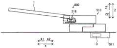
如图1所示,机械手术台100设置于混合手术室200。在混合手术室200设置有X射线摄像装置300,所述X射线摄像装置300对患者10的X射线投影图像进行摄像。设置于混合手术室200的混合手术室系统具备机械手术台100和X射线摄像装置300。机械手术台100例如用作供在外科、内科等中进行手术的手术台。机械手术台100能够移动到将患者10载置于工作台1的载置位置,并且能够在将患者10载置于工作台1的状态下,使患者10移动到麻醉位置、手术位置、检查位置、处理位置、X射线摄像位置等。另外,机械手术台100能够在将患者10载置于工作台1的状态下使患者10倾斜。As shown in FIG. 1 , the mechanical operating table 100 is installed in the
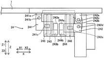
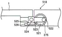
机械手术台100具备:患者载置用的工作台1、多关节机械臂2、以及控制部3。工作台1包括X射线透射部11和支承部12。多关节机械臂2具备:基座21、水平多关节组件22、垂直多关节组件23、以及俯仰转动机构24。水平多关节组件22包括水平关节221、222及223。垂直多关节组件23包括垂直关节231、232及233。X射线摄像装置300包括X射线照射部301、X射线检测部302、以及C形臂303。The mechanical operating table 100 includes a table 1 for placing a patient, an articulated
如图1所示,工作台1形成为大致矩形形状的平板状。另外,大致平坦地形成工作台1的上表面。工作台1在X方向上具有长边方向,在Y方向上具有短边方向。此外,工作台1能够绕上下方向(Z方向)上的轴线旋转,但在这里,将沿着工作台1的长边方向的水平方向设为X方向,将沿着工作台1的短边方向的水平方向设为Y方向。即,X方向以及Y方向表示以工作台1为基准的方向。As shown in FIG. 1 , the table 1 is formed in a substantially rectangular flat plate shape. In addition, the upper surface of the table 1 is formed substantially flat. The table 1 has a long-side direction in the X direction and a short-side direction in the Y direction. In addition, the table 1 is rotatable around the axis in the up-down direction (Z direction), but here, the horizontal direction along the longitudinal direction of the table 1 is referred to as the X direction, and the horizontal direction along the short side of the table 1 is referred to as the X direction. The horizontal direction is set to the Y direction. That is, the X direction and the Y direction indicate directions with reference to the table 1 .
如图1所示,在工作台1的X射线透射部11载置患者10。X射线透射部11沿X1方向配置。X射线透射部11形成为大致矩形形状。X射线透射部11由容易透射X射线的材料形成。X射线透射部11例如由碳素材料(石墨)形成。X射线透射部11例如由碳素纤维强化塑料(CFRP)形成。由此,能够在将患者10载置于X射线透射部11的状态下,对患者10的X射线图像进行摄像。As shown in FIG. 1 , the
工作台1的支承部12与多关节机械臂2连接。支承部12沿X2方向配置。支承部12形成为大致矩形形状。支承部12对X射线透射部11进行支承。支承部12由X射线的透射率比X射线透射部11小的材料形成。支承部12例如由金属形成。支承部12例如由铁材、铝材形成。The
工作台1构成为利用多关节机械臂2进行移动。具体而言,工作台1构成为能够在水平方向的X方向、与X方向正交的水平方向的Y方向、以及与X方向和Y方向正交的作为上下方向的Z方向上移动。另外,工作台1构成为能够绕X方向上的轴线转动(滚转)。另外,工作台1构成为能够绕Y方向上的轴线转动(俯仰)。另外,工作台1构成为能够绕Z方向上的轴线旋转(偏摆)。The table 1 is configured to be moved by the articulated
多关节机械臂2构成为使工作台1移动。如图1所示,多关节机械臂2的一方端被固定于地板的基座21支承,另一方端将工作台1支承为能够移动。具体而言,多关节机械臂2能够绕铅垂方向(Z方向)上的轴线旋转地支承于基座21。另外,多关节机械臂2构成为对工作台1的长边方向(X方向)的X2方向侧的一端附近进行支承。换言之,多关节机械臂2的另一方端对工作台1的一端附近的支承部12进行支承。The articulated
多关节机械臂2构成为利用七个自由度使工作台1移动。具体而言,借助水平多关节组件22,多关节机械臂2具有绕铅垂方向上的转动轴线A1的转动、绕铅垂方向上的转动轴线A2的转动、以及绕铅垂方向上的转动轴线A3的转动这三个自由度。另外,借助垂直多关节组件23,多关节机械臂2具有绕水平方向上的转动轴线B1的转动、绕水平方向上的转动轴线B2的转动、以及绕水平方向上的转动轴线B3的转动这三个自由度。另外,借助俯仰转动机构24,多关节机械臂2具有使工作台1绕短边方向(Y方向)上的转动轴线进行俯仰转动(参照图8以及图9)的这一个自由度。The articulated
如图1所示,基座21埋设并固定于地板。基座21在俯视下(沿Z方向观察)设置在工作台1的移动范围的大致中央附近。As shown in FIG. 1 , the
如图1以及图2所示,水平多关节组件22的一方端支承于基座21。另外,水平多关节组件22的另一方端对垂直多关节组件23的一方端进行支承。水平多关节组件22的水平关节221构成为绕Z方向上的转动轴线A1旋转。水平多关节组件22的水平关节222构成为绕Z方向上的转动轴线A2旋转。水平多关节组件22的水平关节223构成为绕Z方向上的转动轴线A3旋转。As shown in FIGS. 1 and 2 , one end of the
如图1以及图2所示,垂直多关节组件23的一方端支承于水平多关节组件22。另外,垂直多关节组件23的另一方端对工作台1进行支承。具体而言,垂直多关节组件23的另一方端经由俯仰转动机构24对工作台1进行支承。垂直多关节组件23的垂直关节231构成为绕X方向上的转动轴线B1转动。垂直多关节组件23的垂直关节232构成为绕X方向上的转动轴线B2转动。垂直多关节组件23的垂直关节233构成为绕X方向上的转动轴线B3转动。As shown in FIGS. 1 and 2 , one end of the vertical articulated
相邻的关节彼此的间隔分别具有比工作台1的短边方向(Y方向)上的长度小的长度。即,转动轴线A1与转动轴线A2的间隔、转动轴线A2与转动轴线A3的间隔、转动轴线A3与转动轴线B1的间隔、转动轴线B1与转动轴线B2的间隔、和转动轴线B2与转动轴线B3的间隔分别具有比工作台1的短边方向上的长度L3小的长度。The intervals between adjacent joints have lengths smaller than the lengths in the transversal direction (Y direction) of the table 1, respectively. That is, the distance between the rotation axis A1 and the rotation axis A2, the distance between the rotation axis A2 and the rotation axis A3, the distance between the rotation axis A3 and the rotation axis B1, the distance between the rotation axis B1 and the rotation axis B2, and the rotation axis B2 and the rotation axis B3 The intervals of each have a length smaller than the length L3 in the short-side direction of the table 1 .
如图3所示,水平关节221~223以及垂直关节231~233构成为分别由驱动机构25进行驱动。驱动机构25具有:马达251、将马达251的旋转减速而进行传递的减速器252、以及电磁制动器253。水平关节221~223以及垂直关节231~233利用各个马达251的驱动而绕转动轴线转动。另外,水平关节221~223的转动轴线被配置成与减速器252的输出旋转轴线一致。垂直关节231~233的转动轴线被配置成与减速器252的输出旋转轴线一致。As shown in FIG. 3 , the
马达251包括伺服马达。马达251构成为利用控制部3的控制进行驱动。减速器252例如由波动齿轮减速器、偏心摆动型行星齿轮减速器等减速器构成。由此,能够利用小型的减速器252高效地对马达251的旋转进行减速。电磁制动器253构成为对关节的驱动进行制动。The
在此,在第一实施方式中,垂直关节231的转动轴线B1被配置在水平方向且与工作台1的长边方向大致平行的方向(X方向)上。另外,垂直关节232的转动轴线B2被配置在水平方向且与工作台1的长边方向大致平行的方向(X方向)上。另外,垂直关节233的转动轴线B3被配置在水平方向且与工作台1的长边方向大致平行的方向(X方向)上。即,垂直多关节组件23的多个垂直关节231~233各自的转动轴线B1~B3被配置在水平方向且与工作台1的长边方向大致平行的方向(X方向)上。Here, in the first embodiment, the rotation axis B1 of the vertical joint 231 is arranged in the horizontal direction and in the direction (X direction) substantially parallel to the longitudinal direction of the table 1 . In addition, the rotation axis B2 of the vertical joint 232 is arranged in the horizontal direction and in the direction (X direction) substantially parallel to the longitudinal direction of the table 1 . In addition, the rotation axis B3 of the vertical joint 233 is arranged in the horizontal direction and in the direction (X direction) substantially parallel to the longitudinal direction of the table 1 . That is, the respective rotation axes B1 to B3 of the plurality of
垂直多关节组件23构成为相对于工作台1,相对于铅垂方向(Z方向)上的旋转轴线不进行旋转。即,垂直多关节组件23的垂直关节231~233的转动轴线与沿着工作台1的长边方向的水平方向始终大致平行。The
如图4所示,在第一实施方式中,在靠近工作台1的X2侧地配置多关节机械臂2的情况下,作为能够摄像的最大范围,能够利用X射线摄像装置300对在X方向上距离D1的量进行摄像。即,在靠近工作台1的X2侧地配置多关节机械臂2的情况下,在X方向上,能够在工作台1的下方确保距离D1的量的空间。距离D1例如与X射线透射部11的X方向上的长度大致相等。即,在第一实施方式的机械手术台100中,能够利用X射线摄像装置300对患者10的大致全身进行摄像。As shown in FIG. 4 , in the first embodiment, when the articulated
如图5所示,在第一实施方式中,在使多关节机械臂2沿水平方向的X2方向最大限度地延伸的情况下,作为能够摄像的最小范围,能够利用X射线摄像装置300对在X方向上距离D2的量进行摄像。即,在使多关节机械臂2沿水平方向的X2方向最大限度地延伸的情况下,在X方向上,能够在工作台1的下方确保距离D2的量的空间。距离D2例如为X射线透射部11的X方向上的长度的1/2以上。即,在第一实施方式的机械手术台100中,能够利用X射线摄像装置300,最少对患者10的全身的一半以上进行摄像。As shown in FIG. 5 , in the first embodiment, when the
如图2所示,多关节机械臂2被配置成在俯视下(沿Z方向观察)全部隐藏在工作台1的下方。例如,多关节机械臂2构成为:在工作台1位于手术位置的情况下,多关节机械臂2被收容在作为工作台1的下部空间的收容空间内。即,多关节机械臂2构成为:在使工作台1移动到对载置于工作台1的患者10进行手术、处理的位置的情况下,多关节机械臂2被折叠,且在俯视下(沿Z方向观察)完全隐藏在工作台1的下方。另外,折叠的姿势下的多关节机械臂2在与工作台1的长边方向平行的方向上的长度为工作台1的长边方向上的长度的1/2以下。As shown in FIG. 2 , the articulated
本实施方式的多关节机械臂2例如能够使工作台1的高度下降至500mm。由此,能够应对坐在椅子上进行的手术。另外,多关节机械臂2能够将工作台1的高度提升至1100mm。The articulated
另外,在第一实施方式中,多关节机械臂2构成为:利用至少一个水平关节(221、222及223中的至少一个),使工作台1绕铅垂方向(Z方向)上的轴线进行偏摆旋转。例如,多关节机械臂2构成为:利用最下方的水平关节221或最上方的水平关节223,使工作台1进行偏摆旋转。或者,多关节机械臂2构成为:使多个水平关节联动地进行驱动,从而使工作台1进行偏摆旋转。In addition, in the first embodiment, the articulated
另外,如图6所示,多关节机械臂2构成为:利用至少一个垂直关节(231、232及233中的至少一个),使工作台1绕长边方向(X方向)上的轴线进行滚转转动。例如,多关节机械臂2构成为:利用最下方的垂直关节231或最上方的垂直关节233,使工作台1进行滚转转动。或者,多关节机械臂2构成为:使多个垂直关节联动地进行驱动,从而使工作台1进行滚转转动。沿X方向观察,多关节机械臂2能够使工作台1相对于水平方向沿顺时针以角度θ1的范围进行滚转转动,并且,能够使工作台1相对于水平方向沿逆时针以角度θ1的范围进行滚转转动。例如,θ1为30度。In addition, as shown in FIG. 6 , the articulated
另外,如图8以及图9所示,多关节机械臂2构成为:利用俯仰转动机构24,使工作台1绕短边方向(Y方向)上的轴线进行俯仰转动。如图7所示,俯仰转动机构24包括:第一支承构件241、第二支承构件242、第一滚珠丝杠243、第二滚珠丝杠244、第一直线导轨245、以及第二直线导轨246。第一支承构件241包括:连结部241a、转动轴241b、以及滑块241c。第二支承构件242包括:连结部242a及242b、转动轴242c及242d、以及滑块242e。第一滚珠丝杠243经由减速器243b与马达243a连接。第二滚珠丝杠244经由减速器244b与马达244a连接。In addition, as shown in FIGS. 8 and 9 , the articulated
俯仰转动机构24支承于垂直多关节组件23的另一方端。俯仰转动机构24与工作台1连接,并将工作台1支承为能够进行俯仰转动。具体而言,俯仰转动机构24利用第一支承构件241以及第二支承构件242,将工作台1支承为能够进行俯仰转动。第一支承构件241以及第二支承构件242沿着与工作台1的长边方向平行的方向(X方向)隔开预定距离地进行配置。第一支承构件241被配置在X1方向侧。第二支承构件242被配置在X2方向侧。另外,俯仰转动机构24被配置在工作台1的短边方向(Y方向)上的单侧附近。具体而言,俯仰转动机构24被配置在工作台1的Y1方向上的端部附近。The
第一支承构件241的连结部241a固定于工作台1,并且被转动轴241b支承为能够转动。第一支承构件241构成为利用第一滚珠丝杠243的驱动在铅垂方向(Z方向)上移动。另外,第一支承构件241能够滑动移动地安装于第一直线导轨245。具体而言,通过使固定于第一支承构件241的滑块241c与第一直线导轨245卡合,从而对第一支承构件241的铅垂方向上的移动进行导向。The
第二支承构件242的连结部242a固定于工作台1,并且被转动轴242c支承为能够转动。连结部242b能够转动地安装于转动轴242c以及242d。第二支承构件242构成为利用第二滚珠丝杠244的驱动在铅垂方向(Z方向)上移动。另外,第二支承构件242能够滑动移动地安装于第二直线导轨246。具体而言,通过使固定于第二支承构件242的滑块242e与第二直线导轨246卡合,从而对第二支承构件242的铅垂方向上的移动进行导向。The
第一滚珠丝杠243被配置成轴心沿铅垂方向(Z方向)延伸。第一滚珠丝杠243与第一支承构件241卡合。第一滚珠丝杠243利用马达243a的驱动进行旋转,使第一支承构件241在铅垂方向上移动。The
第二滚珠丝杠244被配置成轴心沿铅垂方向(Z方向)延伸。第二滚珠丝杠244与第二支承构件242卡合。第二滚珠丝杠244利用马达244a的驱动进行旋转,使第二支承构件242在铅垂方向上移动。The
第一直线导轨245被配置成在与第一滚珠丝杠243延伸的方向大致平行的方向上延伸。即,第一直线导轨245被配置成沿铅垂方向(Z方向)延伸。第一直线导轨245构成为经由滑块241c对第一支承构件241的铅垂方向上的移动进行导向。The first
第二直线导轨246被配置成在与第二滚珠丝杠244延伸的方向大致平行的方向上延伸。即,第二直线导轨246被配置成沿铅垂方向(Z方向)延伸。第二直线导轨246构成为经由滑块242e对第二支承构件242的铅垂方向上的移动进行导向。The second
在第一支承构件241移动到比第二支承构件242低的位置时,工作台1以X1侧变低的方式进行俯仰转动。另一方面,在第一支承构件241移动到比第二支承构件242高的位置时,工作台1以X1侧变高的方式进行俯仰转动。另外,在第一支承构件241以及第二支承构件242移动到相同的高度位置时,工作台1在俯仰转动中成为水平。When the
如图9所示,沿Y方向观察,多关节机械臂2能够使工作台1相对于水平方向沿顺时针以角度θ2的范围进行俯仰转动,并且,能够使工作台1相对于水平方向沿逆时针以角度θ2的范围进行俯仰转动。例如,θ2为15度。As shown in FIG. 9 , when viewed in the Y direction, the articulated
控制部3设置在基座21内,并构成为对由多关节机械臂2进行的工作台1的移动进行控制。具体而言,控制部3构成为:基于由医疗从业人员(操作人员)进行的操作,对多关节机械臂2的驱动进行控制,从而使工作台1移动。The control unit 3 is provided in the
X射线摄像装置300构成为能够对载置于工作台1的患者10的X射线投影图像进行摄像。X射线照射部301以及X射线检测部302由C形臂303支承。X射线照射部301以及X射线检测部302伴随着C形臂303的移动而移动,并被配置成在进行X射线摄像时,以将患者10的摄像位置夹入的方式相向。例如,X射线照射部301以及X射线检测部302中的一方配置于工作台1的上方空间,另一方配置于工作台1的下方空间。另外,在进行X射线摄像时,支承X射线照射部301以及X射线检测部302的C形臂303也被配置在工作台1的上方空间及下方空间。The
如图1所示,X射线照射部301被配置成与X射线检测部302相向。另外,X射线照射部301构成为能够朝向X射线检测部302照射X射线。X射线检测部302构成为对由X射线照射部301照射的X射线进行检测。X射线检测部302包括平板显示器(FPD)。X射线检测部302构成为基于检测到的X射线对X射线图像进行摄像。具体而言,X射线检测部302将检测到的X射线转换为电信号,并向图像处理部(未图示)发送。As shown in FIG. 1 , the
C形臂303在一方端与X射线照射部301连接,在另一方端与X射线检测部302连接。C形臂303具有大致C字形状。由此,在进行X射线摄像时,能够以不与工作台1、患者10发生干涉的方式绕过(日文:回り込む),对X射线照射部301以及X射线检测部302进行支承。C形臂303构成为相对于工作台1能够相对移动。具体而言,C形臂303构成为:能够在水平方向、铅垂方向上移动,以便将X射线照射部301以及X射线检测部302相对于载置于工作台1的患者10配置在所期望的位置上,并且,C形臂303能够以水平方向上的转动轴线以及铅垂方向上的转动轴线为中心进行转动。C形臂303基于由医疗从业人员(操作人员)进行的操作,利用驱动部(未图示)进行移动。另外,C形臂303构成为能够通过医疗从业人员(操作人员)的手动进行移动。The C-
(第一实施方式的效果)(Effect of the first embodiment)
在第一实施方式中,能够得到如下效果。In the first embodiment, the following effects can be obtained.
在第一实施方式中,如上所述,将多关节机械臂2的垂直关节231、232及233的转动轴线配置在水平方向且与工作台1的长边方向大致平行的方向(X方向)上。在此,为了抑制多关节机械臂2与医疗从业人员、其它装置发生干涉,构成为对工作台1的长边方向上的一端附近进行支承,因此,就从支承位置起到载置有患者10的状态下的工作台1的重心位置为止的距离而言,工作台1的长边方向(X方向)上的距离比工作台1的短边方向(Y方向)上的距离大。其结果是,就多关节机械臂2的工作台1的支承位置处的力矩而言,与绕工作台1的长边方向上的转动轴线转动的力矩相比,绕工作台1的短边方向上的转动轴线转动的力矩更大。由此,通过将多关节机械臂2的垂直关节231、232及233的转动轴线配置在水平方向且与工作台1的长边方向大致平行的方向上,从而能够抑制在使垂直关节231、232及233转动的方向上支撑工作台1的力矩负载变大。换言之,由于能够在垂直关节231、232及233的转动轴线的方向上对工作台1的长边方向上的力矩负载进行支撑,所以不需要增大驱动垂直关节231、232及233的驱动机构25的输出。另外,不需要为了增大驱动机构25的输出转矩而设置较大的减速器。其结果是,能够抑制垂直关节231、232及233变大。由此,能够确保使载置有进行手术的患者10的工作台1移动的多关节机械臂2的垂直关节231、232及233相对于负载的耐性,并且能够谋求多关节机械臂2的小型化。In the first embodiment, as described above, the rotation axes of the
另外,在第一实施方式中,如上所述,多关节机械臂2构成为对工作台1的长边方向(X方向)上的一端附近进行支承。由此,能够在与支承于多关节机械臂2的工作台1的一端侧相反的一侧的工作台1的下方确保空间,所以能够在患者载置用的工作台1的周边确保充分的空间。其结果是,能够抑制多关节机械臂2与医疗从业人员、其它装置发生干涉。In addition, in the first embodiment, as described above, the articulated
另外,在第一实施方式中,如上所述,将多个垂直关节231、232及233各自的转动轴线配置在水平方向且与工作台1的长边方向大致平行的方向(X方向)上。由此,能够确保多个垂直关节231、232及233相对于负载的耐性,并且能够谋求多个垂直关节231、232及233的小型化。In addition, in the first embodiment, as described above, the respective rotation axes of the plurality of
另外,在第一实施方式中,如上所述,在驱动垂直关节231、232及233的驱动机构25设置有:马达251、以及将马达251的旋转减速而进行输出的减速器252,垂直关节231、232及233的转动轴线被配置成与减速器252的输出旋转轴线一致。由此,由于能够利用减速器252增大马达251的输出转矩,所以不需要增大马达251的输出。另外,由于能够将减速器252的输出旋转轴配置在水平方向且与工作台1的长边方向大致平行的方向上,所以能够抑制相对于减速器252的力矩负载变大。Further, in the first embodiment, as described above, the
另外,在第一实施方式中,如上所述,在多关节机械臂2设置有:具有多个水平关节221、222及223的水平多关节组件22、和具有多个垂直关节231、232及233的垂直多关节组件23,并构成为:水平多关节组件22的一方端支承于基座21,另一方端对垂直多关节组件23的一方端进行支承,垂直多关节组件23的另一方端对工作台1进行支承。由此,由于在垂直多关节组件23与工作台1之间,工作台1不会在水平方向上旋转,所以能够维持垂直关节231、232及233的转动轴线的延伸方向与工作台1的长边方向的关系不变,使工作台1沿上下方向以及水平方向移动。另外,能够利用具有多个水平关节221、222及223的水平多关节组件22,使工作台1容易地移动到所期望的水平方向上的位置。另外,能够利用具有多个垂直关节231、232及233的垂直多关节组件23,使工作台1容易地移动到所期望的上下方向上的位置。另外,由于能够将多个水平关节221、222及223集中配置在基座21侧,并将多个垂直关节231、232及233集中配置在工作台1侧,所以针对水平方向上的移动,能够由基座21侧的多个水平关节221、222及223的驱动来进行,针对上下方向上的移动,能够由工作台1侧的多个垂直关节231、232及233的驱动来进行。由此,由于不需要一边使水平关节221、222及223与垂直关节231、232及233联动,一边分别对水平方向以及铅垂方向上的移动进行驱动,所以与交替地配置垂直关节231、232及233和水平关节221、222及223的情况相比,能够抑制多关节机械臂2的驱动控制变得复杂。In addition, in the first embodiment, as described above, the articulated
另外,在第一实施方式中,如上所述,在水平多关节组件22设置有三个水平关节221、222及223,在垂直多关节组件23设置有三个垂直关节231、232及233。由此,在考虑到要确保将水平多关节组件22延伸成最大的情况下的长度时,与设置两个以下的水平关节的情况相比,能够减小关节间的距离,所以在将水平多关节组件22折叠并收缩的情况下,能够使其更为紧凑。另外,与设置四个以上的水平关节的情况相比,能够简化装置结构。在考虑到要确保将垂直多关节组件23延伸成最大的情况下的长度时,与设置两个以下的垂直关节的情况相比,能够减小关节间的距离,所以在将垂直多关节组件23折叠并收缩的情况下,能够使其更为紧凑。另外,与设置四个以上的垂直关节的情况相比,能够简化装置结构。In addition, in the first embodiment, as described above, the
另外,在第一实施方式中,如上所述,多关节机械臂2构成为:利用至少一个水平关节(221、222及223中的至少一个),使工作台1绕铅垂方向(Z方向)上的轴线进行偏摆旋转。由此,能够利用多关节机械臂2的一个以上的水平关节(221、222及223中的至少一个),使工作台1容易地进行偏摆旋转并移动到所期望的位置。Further, in the first embodiment, as described above, the articulated
另外,在第一实施方式中,如上所述,多关节机械臂2构成为:利用至少一个垂直关节(231、232及233中的至少一个),使工作台1绕长边方向(X方向)上的轴线进行滚转转动。由此,能够利用多关节机械臂2的一个以上的垂直关节(231、232及233中的至少一个),使工作台1容易地进行滚转转动并移动到所期望的转动角度位置。In addition, in the first embodiment, as described above, the articulated
另外,在第一实施方式中,如上所述,在多关节机械臂2设置有俯仰转动机构24,所述俯仰转动机构24对工作台1进行支承,并使工作台1绕短边方向(Y方向)上的轴线进行俯仰转动。另外,在俯仰转动机构24设置有:第一滚珠丝杠243,所述第一滚珠丝杠243被配置成轴心沿铅垂方向延伸;第二滚珠丝杠244,所述第二滚珠丝杠244被配置成轴心沿铅垂方向延伸;第一支承构件241,所述第一支承构件241借助第一滚珠丝杠243在铅垂方向(Z方向)上移动,并对工作台1进行支承;以及第二支承构件242,所述第二支承构件242借助第二滚珠丝杠244在铅垂方向(Z方向)上移动,并对工作台1进行支承。并且,第一支承构件241以及第二支承构件242在与工作台1的长边方向平行的方向(X方向)上隔开预定距离地进行配置。由此,通过使第一滚珠丝杠243与第二滚珠丝杠244联动地进行驱动,从而能够使工作台1容易地进行俯仰转动并移动到所期望的转动角度位置。In addition, in the first embodiment, as described above, the articulated
另外,在第一实施方式中,如上所述,在俯仰转动机构24设置有:第一直线导轨245,所述第一直线导轨245被配置成在与第一滚珠丝杠243延伸的方向平行的方向上延伸;以及第二直线导轨246,所述第二直线导轨246被配置成在与第二滚珠丝杠244延伸的方向平行的方向上延伸,第一支承构件241能够滑动移动地安装于第一直线导轨245,第二支承构件242能够滑动移动地安装于第二直线导轨246。由此,能够利用第一直线导轨245使第一支承构件241精度良好地进行直线移动,并且能够利用第二直线导轨246使第二支承构件242精度良好地进行直线移动,所以能够使工作台1精度良好地进行俯仰转动而移动。In addition, in the first embodiment, as described above, the
另外,在第一实施方式中,如上所述,水平多关节组件22构成为:一方端支承于基座21,另一方端对垂直多关节组件23的一方端进行支承,俯仰转动机构24构成为支承于垂直多关节组件23的另一方端。由此,能够将多个水平关节221、222及223集中配置在基座21侧,并将多个垂直关节231、232及233集中配置在工作台1侧,所以针对水平方向上的移动,能够由基座21侧的多个水平关节221、222及223的驱动来进行,针对上下方向上的移动,能够由工作台1侧的多个垂直关节的驱动来进行。由此,由于不需要一边使水平关节221、222及223与垂直关节231、232及233联动,一边分别对水平方向以及铅垂方向上的移动进行驱动,所以与交替地配置垂直关节和水平关节的情况相比,能够抑制多关节机械臂2的驱动控制变得复杂。另外,由于能够将俯仰转动机构24设置在垂直多关节组件23的工作台1侧,所以能够与垂直多关节组件23相独立,利用俯仰转动机构24使工作台1容易地进行俯仰转动而移动。In addition, in the first embodiment, as described above, the horizontal articulated
另外,在第一实施方式中,如上所述,在工作台1设置有X射线透射部11、和对X射线透射部11进行支承的支承部12,多关节机械臂2的另一方端构成为对工作台1的一端附近的支承部12进行支承。由此,只要将多关节机械臂2配置于支承部12侧,在X射线透射部11的下方确保充分的空间,就能够在X射线透射部11的下方放入X射线摄像装置300,所以能够对载置于工作台1的状态下的患者10进行X射线摄像。Further, in the first embodiment, as described above, the table 1 is provided with the X-ray transmissive portion 11 and the
[第二实施方式][Second Embodiment]
接着,参照图10以及图11,对本发明的第二实施方式进行说明。在该第二实施方式中,与多关节机械臂包括具有第一支承构件以及第二支承构件的俯仰转动机构在内的上述第一实施方式不同,对多关节机械臂包括具有俯仰转动支承构件的俯仰转动机构在内的结构的例子进行说明。此外,对与第一实施方式相同的部位标注相同的附图标记。Next, a second embodiment of the present invention will be described with reference to FIGS. 10 and 11 . In this second embodiment, unlike the above-described first embodiment in which the articulated robot arm includes a pitch rotation mechanism having a first support member and a second support member, the articulated robot arm includes a pitch rotation support member. An example of the configuration including the tilt mechanism will be described. In addition, the same code|symbol is attached|subjected to the same part as 1st Embodiment.
(机械手术台的结构)(Structure of mechanical operating table)
如图10所示,机械手术台400具备:患者载置用的工作台1、多关节机械臂2a、以及控制部3。多关节机械臂2a具备:基座21、水平多关节组件22、垂直多关节组件23、以及俯仰转动机构26。水平多关节组件22包括水平关节221、222及223。垂直多关节组件23包括垂直关节231、232及233。俯仰转动机构26包括俯仰转动支承构件261。As shown in FIG. 10 , the mechanical operating table 400 includes a table 1 for placing a patient, an articulated
在此,在第二实施方式中,垂直关节231的转动轴线B1被配置在水平方向且与工作台1的长边方向大致平行的方向(X方向)上。另外,垂直关节232的转动轴线B2被配置在水平方向且与工作台1的长边方向大致平行的方向(X方向)上。另外,垂直关节233的转动轴线B3被配置在水平方向且与工作台1的长边方向大致平行的方向(X方向)上。即,垂直多关节组件23的多个垂直关节231~233各自的转动轴线B1~B3被配置在水平方向且与工作台1的长边方向大致平行的方向(X方向)上。Here, in the second embodiment, the rotation axis B1 of the vertical joint 231 is arranged in the horizontal direction and in the direction (X direction) substantially parallel to the longitudinal direction of the table 1 . In addition, the rotation axis B2 of the vertical joint 232 is arranged in the horizontal direction and in the direction (X direction) substantially parallel to the longitudinal direction of the table 1 . In addition, the rotation axis B3 of the vertical joint 233 is arranged in the horizontal direction and in the direction (X direction) substantially parallel to the longitudinal direction of the table 1 . That is, the respective rotation axes B1 to B3 of the plurality of
另外,在第二实施方式中,多关节机械臂2构成为利用俯仰转动机构26使工作台1绕短边方向(Y方向)上的轴线进行俯仰转动。俯仰转动机构26由垂直多关节组件23支承。另外,俯仰转动机构26对工作台1进行支承。具体而言,俯仰转动机构26对工作台1的X2方向侧的端部附近进行支承。Further, in the second embodiment, the articulated
俯仰转动机构26的俯仰转动支承构件261将工作台1的一端支承为能够绕俯仰转动的转动轴线转动。另外,俯仰转动机构26包括第一俯仰转动支承构件261a、和第二俯仰转动支承构件261b。The pitch
第一俯仰转动支承构件261a将工作台1的一端支承为能够绕与工作台1的短边方向平行的转动轴线C1转动。为了使工作台1进行俯仰转动,在第一俯仰转动支承构件261a设置有:马达、将马达的旋转减速而进行传递的减速器、以及电磁制动器。第二俯仰转动支承构件261b将第一俯仰转动支承构件261a支承为能够绕与工作台1的短边方向平行的转动轴线C2转动。为了使第一俯仰转动支承构件261a进行俯仰转动,在第二俯仰转动支承构件261b设置有:马达、将马达的旋转减速而进行传递的减速器、以及电磁制动器。The first pitch
如图11所示,俯仰转动机构26构成为:通过使第一俯仰转动支承构件261a与第二俯仰转动支承构件261b联动地进行移动,从而使工作台1向铅垂方向的下方(Z2方向)移动。As shown in FIG. 11 , the
此外,第二实施方式的其它结构与上述第一实施方式相同。In addition, other structures of the second embodiment are the same as those of the above-described first embodiment.
(第二实施方式的效果)(Effect of the second embodiment)
在第二实施方式中,能够得到如下效果。In the second embodiment, the following effects can be obtained.
如上所述,在第二实施方式中,与第一实施方式同样地,将多关节机械臂2a的垂直关节231、232及233的转动轴线配置在水平方向且与工作台1的长边方向大致平行的方向(X方向)上。由此,能够确保使载置有进行手术的患者10的工作台1移动的多关节机械臂2a的垂直关节231、232及233相对于负载的耐性,并且能够谋求多关节机械臂2a的小型化。As described above, in the second embodiment, as in the first embodiment, the rotation axes of the
另外,在第二实施方式中,如上所述,在多关节机械臂2a设置有俯仰转动机构26,所述俯仰转动机构26对工作台1进行支承,并使工作台1绕短边方向(Y方向)上的轴线进行俯仰转动,在俯仰转动机构26设置有俯仰转动支承构件261,所述俯仰转动支承构件261将工作台1的一端支承为能够绕俯仰转动的转动轴线转动。由此,能够利用俯仰转动支承构件261对工作台1进行支承,并利用俯仰转动机构26,使工作台1容易地进行俯仰转动并移动到所期望的转动角度位置。In addition, in the second embodiment, as described above, the articulated
另外,在第二实施方式中,如上所述,俯仰转动机构26的俯仰转动支承构件261构成为包括:第一俯仰转动支承构件261a,所述第一俯仰转动支承构件261a将工作台1的一端支承为能够绕与工作台1的短边方向平行的转动轴线转动;以及第二俯仰转动支承构件261b,所述第二俯仰转动支承构件261b将第一俯仰转动支承构件261a支承为能够绕与工作台1的短边方向平行的转动轴线转动。由此,能够利用由第一俯仰转动支承构件261a进行的俯仰转动、和由第二俯仰转动支承构件261b进行的俯仰转动这两个阶段,使工作台1进行俯仰转动,所以能够容易地增大工作台1的能够进行俯仰转动的角度。In addition, in the second embodiment, as described above, the pitch
此外,第二实施方式的其它效果与上述第一实施方式相同。In addition, other effects of the second embodiment are the same as those of the above-described first embodiment.
[第三实施方式][Third Embodiment]
接着,参照图12~图16,对本发明的第三实施方式进行说明。在该第三实施方式中,与多关节机械臂包括具有第一支承构件以及第二支承构件的俯仰转动机构在内的上述第一实施方式不同,对多关节机械臂包括具有连杆机构的俯仰转动机构在内的结构的例子进行说明。此外,对与第一实施方式相同的部位标注相同的附图标记。Next, a third embodiment of the present invention will be described with reference to FIGS. 12 to 16 . In this third embodiment, unlike the above-described first embodiment in which the articulated robot arm includes a pitch rotation mechanism including a first support member and a second support member, the articulated robot arm includes a pitch mechanism including a link mechanism. An example of the structure including the rotating mechanism will be described. In addition, the same code|symbol is attached|subjected to the same part as 1st Embodiment.
(机械手术台的结构)(Structure of mechanical operating table)
如图12所示,机械手术台500具备:患者载置用的工作台1、多关节机械臂510、以及控制部3(参照图13)。多关节机械臂510具备:基座511、包括水平关节512、513及514在内的水平多关节组件、包括垂直关节515、516及517在内的垂直多关节组件、以及俯仰转动机构518。As shown in FIG. 12 , the mechanical operating table 500 includes a table 1 for placing a patient, an articulated
多关节机械臂510构成为利用七个自由度使工作台1移动。具体而言,借助水平多关节组件,多关节机械臂510具有绕铅垂方向上的转动轴线E1的转动、绕铅垂方向上的转动轴线E2的转动、以及绕铅垂方向上的转动轴线E3的转动这三个自由度。另外,借助垂直多关节组件,多关节机械臂510具有绕水平方向上的转动轴线F1的转动、绕水平方向上的转动轴线F2的转动、以及绕水平方向上的转动轴线F3的转动这三个自由度。另外,借助俯仰转动机构518,多关节机械臂510具有使工作台1绕短边方向(Y方向)上的转动轴线进行俯仰转动(参照图13)的这一个自由度。The articulated
在此,在第三实施方式中,将垂直关节515的转动轴线F1配置在水平方向且与工作台1的长边方向大致平行的方向(X方向)上。另外,将垂直关节516的转动轴线F2配置在水平方向且与工作台1的长边方向大致平行的方向(X方向)上。另外,将垂直关节517的转动轴线F3配置在水平方向且与工作台1的长边方向大致平行的方向(X方向)上。即,将垂直多关节组件的多个垂直关节515~517各自的转动轴线F1~F3配置在水平方向且与工作台1的长边方向大致平行的方向(X方向)上。Here, in the third embodiment, the rotation axis F1 of the vertical joint 515 is arranged in the horizontal direction and in the direction (X direction) substantially parallel to the longitudinal direction of the table 1 . In addition, the rotation axis F2 of the vertical joint 516 is arranged in a horizontal direction and a direction (X direction) substantially parallel to the longitudinal direction of the table 1 . In addition, the rotation axis F3 of the vertical joint 517 is arranged in a horizontal direction and a direction (X direction) substantially parallel to the longitudinal direction of the table 1 . That is, the respective rotation axes F1 to F3 of the plurality of
另外,在第三实施方式中,多关节机械臂510构成为利用俯仰转动机构518使工作台1绕短边方向(Y方向)上的轴线进行俯仰转动。俯仰转动机构518由垂直多关节组件支承。另外,俯仰转动机构518对工作台1进行支承。具体而言,俯仰转动机构518对工作台1的X2方向侧的端部附近进行支承。In addition, in the third embodiment, the articulated
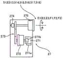
如图14所示,水平关节512~514、垂直关节515~517以及俯仰转动机构518构成为分别由驱动机构27进行驱动。驱动机构27包括:马达271、将马达271的旋转减速而进行输出的第一减速器272、以及将第一减速器272的旋转减速而进行输出的第二减速器275。另外,驱动机构27包括齿轮部273和电磁制动器274。As shown in FIG. 14 , the
另外,马达271具有编码器271a和内置的电磁制动器271b。另外,在第二减速器275的旋转轴安装有电磁制动器274。电磁制动器271b以及274构成为对关节进行制动。编码器271a构成为检测马达271的驱动量,并向控制部3发送检测结果。水平关节512~514的转动轴线被配置成与第二减速器275的输出旋转轴线一致。垂直关节515~517的转动轴线被配置成与第二减速器275的输出旋转轴线一致。In addition, the
马达271包括伺服马达。马达271构成为利用控制部3的控制进行驱动。第一减速器272以及第二减速器275例如由波动齿轮减速器、偏心摆动型行星齿轮减速器等减速器构成。此外,如图3所示,水平关节512~514也可以是包括一个减速器在内的结构。
如图15所示,俯仰转动机构518将工作台1的一端支承为能够绕俯仰转动的转动轴线转动。另外,俯仰转动机构518包括连杆机构,所述连杆机构具有:转动部521、枢轴522、连杆523、枢轴524、滑块525、以及轨道526。如图15以及图16所示,沿Y方向观察,俯仰转动机构518能够使工作台1相对于水平方向以角度θ3的范围进行俯仰转动。As shown in FIG. 15 , the
转动部521构成为与驱动机构27的第二减速器275的输出旋转轴连接,并绕转动轴线转动。连杆523经由枢轴522与转动部521连接。枢轴522从转动部521的转动中心线隔开预定间隔地与转动部521连接。即,通过使转动部521转动,从而使枢轴522沿着转动部521的周向移动。The
另外,连杆523的工作台1侧经由枢轴524与滑块525连接。滑块525构成为能够沿着轨道526在水平方向上移动。另外,连杆523与工作台1连接,以便对工作台1的一端进行支承。即,构成为:通过使连杆523相对于水平方向倾斜,从而使工作台1进行俯仰转动。In addition, the table 1 side of the
如图16所示,在转动部521沿顺时针转动时,枢轴522转动,连杆523的枢轴522侧的端部向下方移动。由此,与枢轴524连接的滑块525向工作台1侧移动,并且连杆523的工作台1侧的端部向上方移动。其结果是,如图16所示,与连杆523连接的工作台1沿顺时针进行俯仰转动。另外,同样地,通过使转动部521沿逆时针转动,从而使工作台1沿逆时针进行俯仰转动。As shown in FIG. 16 , when the
此外,第三实施方式的其它结构与上述第一实施方式相同。In addition, other structures of the third embodiment are the same as those of the above-described first embodiment.
(第三实施方式的效果)(Effect of the third embodiment)
在第三实施方式中,能够得到如下效果。In the third embodiment, the following effects can be obtained.
如上所述,在第三实施方式中,与第一实施方式同样地,将多关节机械臂510的垂直关节515、516及517的转动轴线配置在水平方向且与工作台1的长边方向大致平行的方向(X方向)上。由此,能够确保使载置有进行手术的患者10的工作台1移动的多关节机械臂510的垂直关节515、516及517相对于负载的耐性,并且能够谋求多关节机械臂510的小型化。As described above, in the third embodiment, as in the first embodiment, the rotation axes of the
另外,在第三实施方式中,如上所述,在驱动机构27设置有:马达271、将马达271的旋转减速而进行输出的第一减速器272、以及将第一减速器272的旋转减速而进行输出的第二减速器275,将垂直关节515、516及517的转动轴线配置成与第二减速器275的输出旋转轴线一致。由此,由于能够利用第一减速器272以及第二减速器275在两个阶段进行减速,所以能够有效地增大垂直关节515、516及517的马达271的输出转矩。其结果是,能够减小马达271的最大输出,所以能够减小垂直关节515、516及517的马达271。In addition, in the third embodiment, as described above, the
此外,第三实施方式的其它效果与上述第一实施方式相同。In addition, other effects of the third embodiment are the same as those of the above-described first embodiment.
(变形例)(Variation)
此外,应当认为,此次公开的实施方式在所有的方面都只是例示,而不是限制性的。本发明的范围并不是对上述实施方式的说明,而是由权利要求示出,而且,还包括在与权利要求等同的意思以及范围内进行的所有变更。In addition, it should be understood that the embodiments disclosed this time are illustrative and not restrictive in all points. The scope of the present invention is shown not by the description of the above-described embodiments but by the claims, and includes all modifications within the meaning and scope equivalent to the claims.
例如,在上述第一~第三实施方式中,示出了在混合手术室中与机械手术台一起设置有X射线摄像装置的混合手术室系统的例子,但本发明不限于此。在本发明中,也可以在混合手术室中与机械手术台一起设置对患者的磁共振图像进行摄像的磁共振成像装置。此外,也可以在混合手术室中与机械手术台一起设置X射线摄像装置和磁共振成像装置这双方。For example, in the above-described first to third embodiments, the example of the hybrid operating room system in which the X-ray imaging device is installed in the hybrid operating room together with the mechanical operating table is shown, but the present invention is not limited to this. In the present invention, a magnetic resonance imaging apparatus for capturing a magnetic resonance image of a patient may be installed in a hybrid operating room together with a mechanical operating table. In addition, both the X-ray imaging device and the magnetic resonance imaging device may be installed in the hybrid operating room together with the mechanical operating table.
另外,在上述第一~第三实施方式中,示出了在混合手术室中设置有一台X射线摄像装置的结构的例子,但本发明不限于此。在本发明中,也可以在混合手术室中设置多台X射线摄像装置。Moreover, in the said 1st - 3rd embodiment, the example of the structure which installed one X-ray imaging apparatus in the hybrid operating room was shown, but this invention is not limited to this. In the present invention, a plurality of X-ray imaging apparatuses may be installed in the hybrid operating room.
另外,在上述第一~第三实施方式中,示出了水平多关节组件具有三个水平关节的结构的例子,但本发明不限于此。在本发明中,水平多关节组件既可以具有两个以下的水平关节,也可以具有四个以上的水平关节。Moreover, in the said 1st - 3rd embodiment, the example of the structure in which the horizontal multi-joint unit has three horizontal joints was shown, but this invention is not limited to this. In the present invention, the horizontal multi-joint assembly may have two or less horizontal joints, or may have four or more horizontal joints.
另外,在上述第一~第三实施方式中,示出了垂直多关节组件具有三个垂直关节的结构的例子,但本发明不限于此。在本发明中,垂直多关节组件既可以具有两个以下的垂直关节,也可以具有四个以上的垂直关节。In addition, in the above-described first to third embodiments, the vertical multi-joint assembly has been shown as an example of the structure having three vertical joints, but the present invention is not limited to this. In the present invention, the vertical multi-joint assembly may have two or less vertical joints or more than four vertical joints.
另外,在上述第一及第二实施方式中,示出了水平关节以及垂直关节分别具有伺服马达、减速器和电磁制动器的结构的例子,但本发明不限于此。在本发明中,各个关节也可以具有:内置有第一电磁制动器的伺服马达、第一减速器、第二减速器、以及安装于第二减速器的旋转轴的第二电磁制动器。并且,利用各个伺服马达的驱动,使水平关节以及垂直关节绕转动轴线进行转动。利用这样的结构,能够增大各关节的驱动转矩,并且能够提高各关节的安全性。In addition, in the above-described first and second embodiments, the horizontal joint and the vertical joint have been shown as examples of the configuration in which the servo motor, the speed reducer, and the electromagnetic brake, respectively, are provided, but the present invention is not limited to this. In the present invention, each joint may include a servo motor with a built-in first electromagnetic brake, a first reduction gear, a second reduction gear, and a second electromagnetic brake attached to a rotating shaft of the second reduction gear. Then, the horizontal joint and the vertical joint are rotated around the rotation axis by the drive of each servo motor. With such a configuration, the drive torque of each joint can be increased, and the safety of each joint can be improved.
另外,也可以是,水平关节经由一个减速器进行驱动,垂直关节经由多个减速器进行驱动。In addition, the horizontal joint may be driven through one speed reducer, and the vertical joint may be driven through a plurality of speed reducers.
另外,在上述第一~第三实施方式中,示出了多关节机械臂具有七个自由度的结构的例子,但本发明不限于此。在本发明中,机械臂既可以具有六个以下的自由度,也可以具有八个以上的自由度。In addition, in the above-mentioned first to third embodiments, the example of the structure in which the articulated robot arm has seven degrees of freedom is shown, but the present invention is not limited to this. In the present invention, the robot arm may have six or less degrees of freedom, and may have eight or more degrees of freedom.
另外,在上述第一~第三实施方式中,示出了利用C形臂对X射线照射部和X射线检测部进行支承的C形臂型的X射线摄像装置的例子,但本发明不限于此。在本发明中,X射线摄像装置例如也可以将X射线照射部和X射线检测部配置成在上下方向上相向而进行支承。In addition, in the above-mentioned first to third embodiments, the example of the C-arm type X-ray imaging apparatus in which the X-ray irradiation unit and the X-ray detection unit are supported by the C-arm is shown, but the present invention is not limited to this. In the present invention, for example, the X-ray imaging apparatus may be supported by arranging the X-ray irradiation unit and the X-ray detection unit so as to face each other in the up-down direction.
附图标记说明Description of reference numerals
1:工作台、2、2a、510:多关节机械臂、11:X射线透射部、12:支承部、21、511:基座、22:水平多关节组件、23:垂直多关节组件、24、26、518:俯仰转动机构、25、27:驱动机构、100、400、500:机械手术台、200:混合手术室、221、222、223、512、513、514:水平关节、231、232、233、515、516、517:垂直关节、241:第一支承构件、242:第二支承构件、243:第一滚珠丝杠、244:第二滚珠丝杠、245:第一直线导轨、246:第二直线导轨、251、271:马达、252:减速器、261:俯仰转动支承构件、261a:第一俯仰转动支承构件、261b:第二俯仰转动支承构件、272:第一减速器、275:第二减速器、300:X射线摄像装置。1: table, 2, 2a, 510: multi-joint robotic arm, 11: X-ray transmission part, 12: support part, 21, 511: base, 22: horizontal multi-joint assembly, 23: vertical multi-joint assembly, 24 , 26, 518: Tilt rotation mechanism, 25, 27: Drive mechanism, 100, 400, 500: Mechanical operating table, 200: Hybrid operating room, 221, 222, 223, 512, 513, 514: Horizontal joints, 231, 232 , 233, 515, 516, 517: vertical joint, 241: first support member, 242: second support member, 243: first ball screw, 244: second ball screw, 245: first linear guide, 246: Second linear guide, 251, 271: Motor, 252: Reducer, 261: Pitch rotation support member, 261a: First pitch rotation support member, 261b: Second pitch rotation support member, 272: First reducer, 275: Second speed reducer, 300: X-ray imaging device.
Claims (15)
Applications Claiming Priority (4)
| Application Number | Priority Date | Filing Date | Title |
|---|---|---|---|
| JP2016255014 | 2016-12-28 | ||
| JP2016-255014 | 2016-12-28 | ||
| JP2017-197347 | 2017-10-11 | ||
| JP2017197347AJP6586444B2 (en) | 2016-12-28 | 2017-10-11 | Robotic operating table and hybrid operating room system |
Publications (2)
| Publication Number | Publication Date |
|---|---|
| CN108245357A CN108245357A (en) | 2018-07-06 |
| CN108245357Btrue CN108245357B (en) | 2020-07-14 |
Family
ID=60673797
Family Applications (1)
| Application Number | Title | Priority Date | Filing Date |
|---|---|---|---|
| CN201711209764.1AExpired - Fee RelatedCN108245357B (en) | 2016-12-28 | 2017-11-28 | Mechanical operating table and hybrid operating room system |
Country Status (3)
| Country | Link |
|---|---|
| US (1) | US11045154B2 (en) |
| EP (1) | EP3342389B1 (en) |
| CN (1) | CN108245357B (en) |
Families Citing this family (12)
| Publication number | Priority date | Publication date | Assignee | Title |
|---|---|---|---|---|
| US20170259085A1 (en)* | 2010-04-16 | 2017-09-14 | James P. Bennett | Integrated imaging-cancer treatment apparatus and method of use thereof |
| WO2016164824A1 (en) | 2015-04-09 | 2016-10-13 | Auris Surgical Robotics, Inc. | Surgical system with configurable rail-mounted mechanical arms |
| JP6800058B2 (en)* | 2017-03-23 | 2020-12-16 | 株式会社メディカロイド | How to move the patient placement table |
| KR102264368B1 (en) | 2018-01-17 | 2021-06-17 | 아우리스 헬스, 인코포레이티드 | Surgical platform with adjustable arm support |
| BR112021003450A2 (en)* | 2018-08-24 | 2021-05-18 | Medical Beam Laboratories, Llc | patient positioning system, radiation beam delivery apparatus, method of delivering a therapeutic dose of radiation to a human or animal patient, and patient positioning device |
| CN113453642B (en) | 2019-02-22 | 2025-06-03 | 奥瑞斯健康公司 | Surgical platform with motorized arm for adjustable arm support |
| US10945904B2 (en)* | 2019-03-08 | 2021-03-16 | Auris Health, Inc. | Tilt mechanisms for medical systems and applications |
| US11696806B2 (en) | 2019-07-23 | 2023-07-11 | Verb Surgical Inc. | Strain wave gearing with input to output braking |
| CN112741967B (en)* | 2019-10-29 | 2025-05-09 | 中硼(厦门)医疗器械有限公司 | Radiation therapy system |
| CN113441938A (en)* | 2020-03-24 | 2021-09-28 | 南宁富桂精密工业有限公司 | Method and system for controlling screw locking sequence |
| CN114198455A (en)* | 2021-12-15 | 2022-03-18 | 上海新纪元机器人有限公司 | Self-balancing vibration damping system mounted on carrying equipment |
| CN114533276A (en)* | 2022-02-24 | 2022-05-27 | 上海神玑医疗科技有限公司 | Positioning mechanical arm and auxiliary operation system for vascular intervention operation |
Family Cites Families (32)
| Publication number | Priority date | Publication date | Assignee | Title |
|---|---|---|---|---|
| US2522759A (en)* | 1947-10-23 | 1950-09-19 | Lindquist Marie | Adjustable bed |
| US3754749A (en)* | 1971-06-25 | 1973-08-28 | Medical Eng Dev Co | Multi-articulated table |
| FR2644687B1 (en)* | 1989-03-23 | 1997-11-14 | Genral Electric Cgr Sa | PATIENT SUPPORT WITH LARGE VERTICAL TRAVEL |
| US5230112A (en)* | 1990-11-21 | 1993-07-27 | Diasonics, Inc. | Patient support table |
| US5337627A (en)* | 1991-12-27 | 1994-08-16 | Nissei Plastic Industrial Co., Ltd. | Ball screw |
| SE9203643D0 (en)* | 1992-12-03 | 1992-12-03 | Siemens Elema Ab | UNDERSOEKNINGSBORD |
| US5398356A (en)* | 1993-06-28 | 1995-03-21 | Pfleger; Frederick W. | X-ray table |
| GB9610129D0 (en)* | 1996-05-15 | 1996-07-24 | Philips Electronics Nv | Patient support |
| US6675037B1 (en)* | 1999-09-29 | 2004-01-06 | Regents Of The University Of Minnesota | MRI-guided interventional mammary procedures |
| SE522789C2 (en)* | 2000-03-29 | 2004-03-09 | Stille Surgical Ab | Operating table |
| US6507964B1 (en)* | 2000-06-12 | 2003-01-21 | Stryker Corporation | Surgical table |
| US8160205B2 (en)* | 2004-04-06 | 2012-04-17 | Accuray Incorporated | Robotic arm for patient positioning assembly |
| US7860550B2 (en)* | 2004-04-06 | 2010-12-28 | Accuray, Inc. | Patient positioning assembly |
| DE102004062473B4 (en)* | 2004-09-30 | 2006-11-30 | Siemens Ag | Medical radiation therapy arrangement |
| US20070162152A1 (en)* | 2005-03-31 | 2007-07-12 | Massachusetts Institute Of Technology | Artificial joints using agonist-antagonist actuators |
| DE102007026114A1 (en)* | 2007-06-05 | 2008-12-11 | Siemens Ag | Positioning device and method for positioning a load and medical diagnostic and / or therapy system |
| EP2190530B1 (en)* | 2007-09-13 | 2017-11-08 | Toby D. Henderson | Patient positioner system |
| US8126114B2 (en)* | 2008-09-12 | 2012-02-28 | Accuray Incorporated | Seven or more degrees of freedom robotic manipulator having at least one redundant joint |
| FR2937854B1 (en)* | 2008-10-31 | 2010-12-03 | Aripa Services Innovations Ind | DEVICE FOR POSITIONING A PATIENT IN RELATION TO RADIATION. |
| US8327971B2 (en)* | 2009-09-24 | 2012-12-11 | Mando Corporation | Reducer of electric power steering apparatus |
| JP5378593B2 (en)* | 2010-03-24 | 2013-12-25 | アスモ株式会社 | Reduction mechanism, motor with reduction mechanism, and method of manufacturing reduction mechanism |
| JP5447455B2 (en)* | 2011-08-19 | 2014-03-19 | 株式会社安川電機 | Robot and robot system |
| WO2013058806A1 (en)* | 2011-10-17 | 2013-04-25 | Jackson Roger P | Patient positioning support structure |
| US8904582B2 (en)* | 2012-04-23 | 2014-12-09 | Elekta Ab | Patient support system |
| JP5338000B1 (en)* | 2012-06-15 | 2013-11-06 | 株式会社アキュセラ | Real-time 3D radiotherapy device |
| US9662256B2 (en)* | 2012-07-31 | 2017-05-30 | Varian Medical Systems Uk Limited | Patient positioning and support systems |
| US9326907B2 (en)* | 2012-07-31 | 2016-05-03 | Varian Medical Systems, Inc. | Patient positioning and support systems |
| DE102013223486A1 (en)* | 2013-11-18 | 2015-05-21 | Berchtold Holding AG | operating table |
| EP2944259A1 (en)* | 2014-05-15 | 2015-11-18 | Buck Engineering & Consulting GmbH | Patient positioning device |
| EP3160354B8 (en)* | 2014-06-26 | 2020-12-02 | Frencken Europe B.V. | Patient support system and levelling system for such a patient support system |
| DE102014109375A1 (en)* | 2014-07-04 | 2016-01-07 | MAQUET GmbH | Operating table column for an operating table |
| US10806409B2 (en)* | 2016-09-23 | 2020-10-20 | Varian Medical Systems International Ag | Medical systems with patient supports |
- 2017
- 2017-11-28CNCN201711209764.1Apatent/CN108245357B/ennot_activeExpired - Fee Related
- 2017-12-18EPEP17207993.1Apatent/EP3342389B1/enactiveActive
- 2017-12-27USUS15/855,909patent/US11045154B2/enactiveActive
Also Published As
| Publication number | Publication date |
|---|---|
| US11045154B2 (en) | 2021-06-29 |
| EP3342389A1 (en) | 2018-07-04 |
| CN108245357A (en) | 2018-07-06 |
| US20180177470A1 (en) | 2018-06-28 |
| EP3342389B1 (en) | 2019-12-11 |
Similar Documents
| Publication | Publication Date | Title |
|---|---|---|
| CN108245357B (en) | Mechanical operating table and hybrid operating room system | |
| CN108245359B (en) | Robot operating table and hybrid operating room | |
| JP6449958B2 (en) | Robotic operating table | |
| KR102186510B1 (en) | Redundant axis and degree of freedom for hardware-constrained remote center robotic manipulator | |
| JP6800058B2 (en) | How to move the patient placement table | |
| US20160361218A1 (en) | Person Support Apparatuses Including Person Repositioning Assemblies | |
| JP6216858B1 (en) | Robotic operating table | |
| US9352468B2 (en) | Manipulator | |
| KR102196198B1 (en) | Robots and robot assemblies for patient positioning | |
| WO2013176142A1 (en) | X-ray imaging device | |
| US9282937B2 (en) | Couch with patient-inclining device | |
| JP6895261B2 (en) | Joint drive mechanism of articulated robot arm, articulated robot arm and robot operating table | |
| CN101185576A (en) | Urinary system X-ray contrast table | |
| JP6586444B2 (en) | Robotic operating table and hybrid operating room system | |
| CN119095548A (en) | Table mounted manipulator system and related apparatus, system and method | |
| CN205814428U (en) | A kind of pose mechanical conditioning type moveable platform | |
| JP6270957B1 (en) | Robotic operating table | |
| JP2018086192A (en) | Robotic operating table | |
| JP5504705B2 (en) | X-ray equipment | |
| JP6708768B2 (en) | Robotic operating table and hybrid operating room | |
| JP6449957B2 (en) | Robotic operating table | |
| US11229415B2 (en) | Radiographic imaging apparatus | |
| WO2023195150A1 (en) | Robot device |
Legal Events
| Date | Code | Title | Description |
|---|---|---|---|
| PB01 | Publication | ||
| PB01 | Publication | ||
| SE01 | Entry into force of request for substantive examination | ||
| SE01 | Entry into force of request for substantive examination | ||
| GR01 | Patent grant | ||
| GR01 | Patent grant | ||
| CF01 | Termination of patent right due to non-payment of annual fee | Granted publication date:20200714 | |
| CF01 | Termination of patent right due to non-payment of annual fee |