CN108245247B - Catheter with tapered support member for variable arc distal assembly - Google Patents
Catheter with tapered support member for variable arc distal assemblyDownload PDFInfo
- Publication number
- CN108245247B CN108245247BCN201711467173.4ACN201711467173ACN108245247BCN 108245247 BCN108245247 BCN 108245247BCN 201711467173 ACN201711467173 ACN 201711467173ACN 108245247 BCN108245247 BCN 108245247B
- Authority
- CN
- China
- Prior art keywords
- distal
- support member
- wire
- catheter
- section
- Prior art date
- Legal status (The legal status is an assumption and is not a legal conclusion. Google has not performed a legal analysis and makes no representation as to the accuracy of the status listed.)
- Active
Links
Images


Classifications
- A—HUMAN NECESSITIES
- A61—MEDICAL OR VETERINARY SCIENCE; HYGIENE
- A61B—DIAGNOSIS; SURGERY; IDENTIFICATION
- A61B18/00—Surgical instruments, devices or methods for transferring non-mechanical forms of energy to or from the body
- A61B18/04—Surgical instruments, devices or methods for transferring non-mechanical forms of energy to or from the body by heating
- A61B18/12—Surgical instruments, devices or methods for transferring non-mechanical forms of energy to or from the body by heating by passing a current through the tissue to be heated, e.g. high-frequency current
- A61B18/14—Probes or electrodes therefor
- A61B18/1492—Probes or electrodes therefor having a flexible, catheter-like structure, e.g. for heart ablation
- A—HUMAN NECESSITIES
- A61—MEDICAL OR VETERINARY SCIENCE; HYGIENE
- A61B—DIAGNOSIS; SURGERY; IDENTIFICATION
- A61B18/00—Surgical instruments, devices or methods for transferring non-mechanical forms of energy to or from the body
- A61B18/04—Surgical instruments, devices or methods for transferring non-mechanical forms of energy to or from the body by heating
- A61B18/12—Surgical instruments, devices or methods for transferring non-mechanical forms of energy to or from the body by heating by passing a current through the tissue to be heated, e.g. high-frequency current
- A61B18/14—Probes or electrodes therefor
- A—HUMAN NECESSITIES
- A61—MEDICAL OR VETERINARY SCIENCE; HYGIENE
- A61B—DIAGNOSIS; SURGERY; IDENTIFICATION
- A61B5/00—Measuring for diagnostic purposes; Identification of persons
- A61B5/24—Detecting, measuring or recording bioelectric or biomagnetic signals of the body or parts thereof
- A61B5/25—Bioelectric electrodes therefor
- A61B5/279—Bioelectric electrodes therefor specially adapted for particular uses
- A61B5/28—Bioelectric electrodes therefor specially adapted for particular uses for electrocardiography [ECG]
- A61B5/283—Invasive
- A61B5/287—Holders for multiple electrodes, e.g. electrode catheters for electrophysiological study [EPS]
- A—HUMAN NECESSITIES
- A61—MEDICAL OR VETERINARY SCIENCE; HYGIENE
- A61B—DIAGNOSIS; SURGERY; IDENTIFICATION
- A61B5/00—Measuring for diagnostic purposes; Identification of persons
- A61B5/68—Arrangements of detecting, measuring or recording means, e.g. sensors, in relation to patient
- A61B5/6846—Arrangements of detecting, measuring or recording means, e.g. sensors, in relation to patient specially adapted to be brought in contact with an internal body part, i.e. invasive
- A61B5/6847—Arrangements of detecting, measuring or recording means, e.g. sensors, in relation to patient specially adapted to be brought in contact with an internal body part, i.e. invasive mounted on an invasive device
- A61B5/6852—Catheters
- A—HUMAN NECESSITIES
- A61—MEDICAL OR VETERINARY SCIENCE; HYGIENE
- A61M—DEVICES FOR INTRODUCING MEDIA INTO, OR ONTO, THE BODY; DEVICES FOR TRANSDUCING BODY MEDIA OR FOR TAKING MEDIA FROM THE BODY; DEVICES FOR PRODUCING OR ENDING SLEEP OR STUPOR
- A61M25/00—Catheters; Hollow probes
- A61M25/0021—Catheters; Hollow probes characterised by the form of the tubing
- A61M25/0023—Catheters; Hollow probes characterised by the form of the tubing by the form of the lumen, e.g. cross-section, variable diameter
- A—HUMAN NECESSITIES
- A61—MEDICAL OR VETERINARY SCIENCE; HYGIENE
- A61M—DEVICES FOR INTRODUCING MEDIA INTO, OR ONTO, THE BODY; DEVICES FOR TRANSDUCING BODY MEDIA OR FOR TAKING MEDIA FROM THE BODY; DEVICES FOR PRODUCING OR ENDING SLEEP OR STUPOR
- A61M25/00—Catheters; Hollow probes
- A61M25/0043—Catheters; Hollow probes characterised by structural features
- A—HUMAN NECESSITIES
- A61—MEDICAL OR VETERINARY SCIENCE; HYGIENE
- A61M—DEVICES FOR INTRODUCING MEDIA INTO, OR ONTO, THE BODY; DEVICES FOR TRANSDUCING BODY MEDIA OR FOR TAKING MEDIA FROM THE BODY; DEVICES FOR PRODUCING OR ENDING SLEEP OR STUPOR
- A61M25/00—Catheters; Hollow probes
- A61M25/01—Introducing, guiding, advancing, emplacing or holding catheters
- A61M25/0105—Steering means as part of the catheter or advancing means; Markers for positioning
- A61M25/0133—Tip steering devices
- A61M25/0147—Tip steering devices with movable mechanical means, e.g. pull wires
- A—HUMAN NECESSITIES
- A61—MEDICAL OR VETERINARY SCIENCE; HYGIENE
- A61B—DIAGNOSIS; SURGERY; IDENTIFICATION
- A61B17/00—Surgical instruments, devices or methods
- A61B2017/00017—Electrical control of surgical instruments
- A61B2017/00022—Sensing or detecting at the treatment site
- A61B2017/00039—Electric or electromagnetic phenomena other than conductivity, e.g. capacity, inductivity, Hall effect
- A61B2017/00044—Sensing electrocardiography, i.e. ECG
- A61B2017/00048—Spectral analysis
- A61B2017/00053—Mapping
- A—HUMAN NECESSITIES
- A61—MEDICAL OR VETERINARY SCIENCE; HYGIENE
- A61B—DIAGNOSIS; SURGERY; IDENTIFICATION
- A61B17/00—Surgical instruments, devices or methods
- A61B2017/00831—Material properties
- A61B2017/00867—Material properties shape memory effect
- A—HUMAN NECESSITIES
- A61—MEDICAL OR VETERINARY SCIENCE; HYGIENE
- A61B—DIAGNOSIS; SURGERY; IDENTIFICATION
- A61B18/00—Surgical instruments, devices or methods for transferring non-mechanical forms of energy to or from the body
- A61B2018/00005—Cooling or heating of the probe or tissue immediately surrounding the probe
- A61B2018/00011—Cooling or heating of the probe or tissue immediately surrounding the probe with fluids
- A61B2018/00029—Cooling or heating of the probe or tissue immediately surrounding the probe with fluids open
- A—HUMAN NECESSITIES
- A61—MEDICAL OR VETERINARY SCIENCE; HYGIENE
- A61B—DIAGNOSIS; SURGERY; IDENTIFICATION
- A61B18/00—Surgical instruments, devices or methods for transferring non-mechanical forms of energy to or from the body
- A61B2018/00053—Mechanical features of the instrument of device
- A61B2018/0016—Energy applicators arranged in a two- or three dimensional array
- A—HUMAN NECESSITIES
- A61—MEDICAL OR VETERINARY SCIENCE; HYGIENE
- A61B—DIAGNOSIS; SURGERY; IDENTIFICATION
- A61B18/00—Surgical instruments, devices or methods for transferring non-mechanical forms of energy to or from the body
- A61B2018/00053—Mechanical features of the instrument of device
- A61B2018/00184—Moving parts
- A61B2018/00196—Moving parts reciprocating lengthwise
- A—HUMAN NECESSITIES
- A61—MEDICAL OR VETERINARY SCIENCE; HYGIENE
- A61B—DIAGNOSIS; SURGERY; IDENTIFICATION
- A61B18/00—Surgical instruments, devices or methods for transferring non-mechanical forms of energy to or from the body
- A61B2018/00315—Surgical instruments, devices or methods for transferring non-mechanical forms of energy to or from the body for treatment of particular body parts
- A61B2018/00345—Vascular system
- A61B2018/00351—Heart
- A61B2018/00357—Endocardium
- A—HUMAN NECESSITIES
- A61—MEDICAL OR VETERINARY SCIENCE; HYGIENE
- A61B—DIAGNOSIS; SURGERY; IDENTIFICATION
- A61B18/00—Surgical instruments, devices or methods for transferring non-mechanical forms of energy to or from the body
- A61B2018/00315—Surgical instruments, devices or methods for transferring non-mechanical forms of energy to or from the body for treatment of particular body parts
- A61B2018/00345—Vascular system
- A61B2018/00351—Heart
- A61B2018/00375—Ostium, e.g. ostium of pulmonary vein or artery
- A—HUMAN NECESSITIES
- A61—MEDICAL OR VETERINARY SCIENCE; HYGIENE
- A61B—DIAGNOSIS; SURGERY; IDENTIFICATION
- A61B18/00—Surgical instruments, devices or methods for transferring non-mechanical forms of energy to or from the body
- A61B2018/00315—Surgical instruments, devices or methods for transferring non-mechanical forms of energy to or from the body for treatment of particular body parts
- A61B2018/00345—Vascular system
- A61B2018/00351—Heart
- A61B2018/00386—Coronary vessels
- A—HUMAN NECESSITIES
- A61—MEDICAL OR VETERINARY SCIENCE; HYGIENE
- A61B—DIAGNOSIS; SURGERY; IDENTIFICATION
- A61B18/00—Surgical instruments, devices or methods for transferring non-mechanical forms of energy to or from the body
- A61B2018/00571—Surgical instruments, devices or methods for transferring non-mechanical forms of energy to or from the body for achieving a particular surgical effect
- A61B2018/00577—Ablation
- A—HUMAN NECESSITIES
- A61—MEDICAL OR VETERINARY SCIENCE; HYGIENE
- A61B—DIAGNOSIS; SURGERY; IDENTIFICATION
- A61B18/00—Surgical instruments, devices or methods for transferring non-mechanical forms of energy to or from the body
- A61B2018/00636—Sensing and controlling the application of energy
- A61B2018/00642—Sensing and controlling the application of energy with feedback, i.e. closed loop control
- A61B2018/00648—Sensing and controlling the application of energy with feedback, i.e. closed loop control using more than one sensed parameter
- A—HUMAN NECESSITIES
- A61—MEDICAL OR VETERINARY SCIENCE; HYGIENE
- A61B—DIAGNOSIS; SURGERY; IDENTIFICATION
- A61B18/00—Surgical instruments, devices or methods for transferring non-mechanical forms of energy to or from the body
- A61B2018/00636—Sensing and controlling the application of energy
- A61B2018/00773—Sensed parameters
- A61B2018/00791—Temperature
- A61B2018/00797—Temperature measured by multiple temperature sensors
- A—HUMAN NECESSITIES
- A61—MEDICAL OR VETERINARY SCIENCE; HYGIENE
- A61B—DIAGNOSIS; SURGERY; IDENTIFICATION
- A61B18/00—Surgical instruments, devices or methods for transferring non-mechanical forms of energy to or from the body
- A61B2018/00636—Sensing and controlling the application of energy
- A61B2018/00773—Sensed parameters
- A61B2018/00791—Temperature
- A61B2018/00821—Temperature measured by a thermocouple
- A—HUMAN NECESSITIES
- A61—MEDICAL OR VETERINARY SCIENCE; HYGIENE
- A61B—DIAGNOSIS; SURGERY; IDENTIFICATION
- A61B18/00—Surgical instruments, devices or methods for transferring non-mechanical forms of energy to or from the body
- A61B2018/00636—Sensing and controlling the application of energy
- A61B2018/00773—Sensed parameters
- A61B2018/00839—Bioelectrical parameters, e.g. ECG, EEG
- A—HUMAN NECESSITIES
- A61—MEDICAL OR VETERINARY SCIENCE; HYGIENE
- A61B—DIAGNOSIS; SURGERY; IDENTIFICATION
- A61B18/00—Surgical instruments, devices or methods for transferring non-mechanical forms of energy to or from the body
- A61B18/04—Surgical instruments, devices or methods for transferring non-mechanical forms of energy to or from the body by heating
- A61B18/12—Surgical instruments, devices or methods for transferring non-mechanical forms of energy to or from the body by heating by passing a current through the tissue to be heated, e.g. high-frequency current
- A61B18/14—Probes or electrodes therefor
- A61B2018/1405—Electrodes having a specific shape
- A61B2018/1407—Loop
- A61B2018/141—Snare
- A—HUMAN NECESSITIES
- A61—MEDICAL OR VETERINARY SCIENCE; HYGIENE
- A61B—DIAGNOSIS; SURGERY; IDENTIFICATION
- A61B18/00—Surgical instruments, devices or methods for transferring non-mechanical forms of energy to or from the body
- A61B18/04—Surgical instruments, devices or methods for transferring non-mechanical forms of energy to or from the body by heating
- A61B18/12—Surgical instruments, devices or methods for transferring non-mechanical forms of energy to or from the body by heating by passing a current through the tissue to be heated, e.g. high-frequency current
- A61B18/14—Probes or electrodes therefor
- A61B2018/1405—Electrodes having a specific shape
- A61B2018/1435—Spiral
- A—HUMAN NECESSITIES
- A61—MEDICAL OR VETERINARY SCIENCE; HYGIENE
- A61B—DIAGNOSIS; SURGERY; IDENTIFICATION
- A61B18/00—Surgical instruments, devices or methods for transferring non-mechanical forms of energy to or from the body
- A61B18/04—Surgical instruments, devices or methods for transferring non-mechanical forms of energy to or from the body by heating
- A61B18/12—Surgical instruments, devices or methods for transferring non-mechanical forms of energy to or from the body by heating by passing a current through the tissue to be heated, e.g. high-frequency current
- A61B18/14—Probes or electrodes therefor
- A61B2018/1467—Probes or electrodes therefor using more than two electrodes on a single probe
- A—HUMAN NECESSITIES
- A61—MEDICAL OR VETERINARY SCIENCE; HYGIENE
- A61B—DIAGNOSIS; SURGERY; IDENTIFICATION
- A61B2218/00—Details of surgical instruments, devices or methods for transferring non-mechanical forms of energy to or from the body
- A61B2218/001—Details of surgical instruments, devices or methods for transferring non-mechanical forms of energy to or from the body having means for irrigation and/or aspiration of substances to and/or from the surgical site
- A61B2218/002—Irrigation
- A—HUMAN NECESSITIES
- A61—MEDICAL OR VETERINARY SCIENCE; HYGIENE
- A61M—DEVICES FOR INTRODUCING MEDIA INTO, OR ONTO, THE BODY; DEVICES FOR TRANSDUCING BODY MEDIA OR FOR TAKING MEDIA FROM THE BODY; DEVICES FOR PRODUCING OR ENDING SLEEP OR STUPOR
- A61M25/00—Catheters; Hollow probes
- A61M25/01—Introducing, guiding, advancing, emplacing or holding catheters
- A61M25/0105—Steering means as part of the catheter or advancing means; Markers for positioning
- A61M25/0133—Tip steering devices
- A61M2025/0163—Looped catheters
- A—HUMAN NECESSITIES
- A61—MEDICAL OR VETERINARY SCIENCE; HYGIENE
- A61M—DEVICES FOR INTRODUCING MEDIA INTO, OR ONTO, THE BODY; DEVICES FOR TRANSDUCING BODY MEDIA OR FOR TAKING MEDIA FROM THE BODY; DEVICES FOR PRODUCING OR ENDING SLEEP OR STUPOR
- A61M25/00—Catheters; Hollow probes
- A61M25/01—Introducing, guiding, advancing, emplacing or holding catheters
- A61M25/0105—Steering means as part of the catheter or advancing means; Markers for positioning
- A61M2025/0166—Sensors, electrodes or the like for guiding the catheter to a target zone, e.g. image guided or magnetically guided
Landscapes
- Health & Medical Sciences (AREA)
- Life Sciences & Earth Sciences (AREA)
- Engineering & Computer Science (AREA)
- Surgery (AREA)
- Veterinary Medicine (AREA)
- Biomedical Technology (AREA)
- Heart & Thoracic Surgery (AREA)
- Animal Behavior & Ethology (AREA)
- General Health & Medical Sciences (AREA)
- Public Health (AREA)
- Molecular Biology (AREA)
- Medical Informatics (AREA)
- Physics & Mathematics (AREA)
- Biophysics (AREA)
- Nuclear Medicine, Radiotherapy & Molecular Imaging (AREA)
- Otolaryngology (AREA)
- Plasma & Fusion (AREA)
- Cardiology (AREA)
- Anesthesiology (AREA)
- Pulmonology (AREA)
- Hematology (AREA)
- Pathology (AREA)
- Mechanical Engineering (AREA)
- Physiology (AREA)
- Media Introduction/Drainage Providing Device (AREA)
- Surgical Instruments (AREA)
Abstract
Description
Translated fromChinese技术领域technical field
本发明整体涉及用于侵入式医疗治疗的方法和装置,并且具体地涉及导管,尤其是具有适于标测和/或消融所选择的解剖结构的远侧节段的导管。The present invention relates generally to methods and devices for invasive medical treatments, and in particular to catheters, especially catheters having a distal segment suitable for mapping and/or ablating selected anatomical structures.
背景技术Background technique
心肌组织消融作为心律失常的治疗手段为人们所熟知。例如,在射频(RF)消融中,将导管插入心脏内并在目标位置处与组织接触。然后通过导管上的电极施加RF能量,以便形成消融灶,其目的是破坏组织中的致心律失常电流通路。Ablation of myocardial tissue is well known as a treatment for cardiac arrhythmias. For example, in radiofrequency (RF) ablation, a catheter is inserted into the heart and brought into contact with tissue at the target location. RF energy is then applied through electrodes on the catheter to create an ablation lesion with the goal of disrupting the arrhythmogenic electrical pathway in the tissue.
现在,肺静脉口的周边消融作为心房心律失常、尤其是心房纤颤的治疗手段被接受。例如,美国专利号6,064,902描述了用于消融血管诸如肺静脉的内壁上的组织的导管,该专利的公开内容以引用方式并入本文。导管的末端部分可从大致直的第一构型(其中近侧节段和远侧节段为基本上共线的)偏转至J形的第二构型(其中近侧节段和远侧节段大致平行,它们之间的间距基本上对应于血管的内径)。导管的远端部分围绕导管的纵向轴线旋转,以使导管上的近侧消融电极和远侧消融电极沿肺静脉的内壁进行周向位移。这样,可使用电极导管通过在每个周向位置处消融一个或两个位点而在肺静脉的内壁上消融数个周向间隔的位点。Peripheral ablation of the pulmonary vein ostia is now accepted as a treatment for atrial arrhythmias, especially atrial fibrillation. For example, US Patent No. 6,064,902, the disclosure of which is incorporated herein by reference, describes a catheter for ablating tissue on the inner wall of a blood vessel, such as a pulmonary vein. The tip portion of the catheter is deflectable from a generally straight first configuration (wherein the proximal section and the distal section are substantially collinear) to a J-shaped second configuration (wherein the proximal section and the distal section The segments are approximately parallel, and the spacing between them corresponds substantially to the inner diameter of the blood vessel). The distal portion of the catheter is rotated about the longitudinal axis of the catheter to displace the proximal and distal ablation electrodes on the catheter circumferentially along the inner wall of the pulmonary vein. In this way, the electrode catheter can be used to ablate several circumferentially spaced sites on the inner wall of the pulmonary vein by ablating one or two sites at each circumferential position.
美国专利号6,973,339描述了用于肺静脉标测和消融的环状导管,该专利的公开内容以引用方式并入本文。用于周向标测肺静脉(PV)的导管包括弯曲节段,该弯曲节段的形状设定为大致适形于PV的内表面的形状。弯曲节段通过处于“边缘上”构型的大致直的轴向基部节段连接到导管,其中基部轴向节段在弯曲节段的圆周上连接到弯曲节段。该弯曲节段包括一个或多个感测电极,并且其近侧端部以固定或通常已知的角度接合到导管的基部节段。位置传感器被固定到导管的弯曲节段并固定到基部节段的远侧端部。导管被插入到心脏中,并且弯曲节段被定位成与PV的壁接触,同时基部节段保留在左心房内,通常被定位成使得具有弯曲节段的接头位于静脉口处。通过三个位置传感器生成的信息被用来计算感测电极的位置和取向,这使得能够标测PV的表面。感测电极可附加地执行对所选择的位点的消融,或者导管可还包括消融元件。US Patent No. 6,973,339 describes a loop catheter for pulmonary vein mapping and ablation, the disclosure of which is incorporated herein by reference. A catheter for circumferentially mapping a pulmonary vein (PV) includes a curved segment that is shaped to generally conform to the shape of the interior surface of the PV. The curved section is connected to the catheter by a generally straight axial base section in an "on-edge" configuration, wherein the base axial section is connected to the curved section on the circumference of the curved section. The curved section includes one or more sensing electrodes and its proximal end is joined to the base section of the catheter at a fixed or generally known angle. A position sensor is secured to the curved section of the catheter and to the distal end of the base section. The catheter is inserted into the heart and the curved section is positioned in contact with the wall of the PV while the base section remains within the left atrium, typically positioned so that the connector with the curved section is at the ostia. The information generated by the three position sensors is used to calculate the position and orientation of the sensing electrodes, which enables mapping of the surface of the PV. The sensing electrodes may additionally perform ablation of the selected site, or the catheter may also include an ablation element.
美国专利号7,008,401描述了可用于诊断和治疗应用二者中的复合转向组件,这些组件用于将导管的远侧节段转向成处于多个平面或复杂曲线,该专利的公开内容以引用方式并入本文。据称,这些组件使得医师能够快速准确地将消融和/或标测电极定位并保持与内部身体表面紧密接触。美国专利号5,820,591类似地描述了这类复合转向组件,该专利的公开内容以引用方式并入本文。U.S. Patent No. 7,008,401 describes compound steering assemblies useful in both diagnostic and therapeutic applications for steering the distal section of a catheter into multiple planes or complex curves, the disclosure of which is incorporated by reference. into this article. These assemblies are said to allow physicians to quickly and accurately position ablation and/or mapping electrodes while maintaining intimate contact with internal body surfaces. This type of compound steering assembly is similarly described in US Patent No. 5,820,591, the disclosure of which is incorporated herein by reference.
美国专利号8,608,735描述了包括具有纵向轴线并且具有适于插入到患者体内的远侧端部的插入轴的医疗装置,该专利的公开内容以引用方式并入本文。有回弹力的末端节段被固定到插入轴的远侧端部,并且被形成为在其不受约束时限定相对于该轴线倾斜取向并且具有轴线上的曲率中心的弧形。一个或多个电极被设置在沿末端节段的相应位置处。US Patent No. 8,608,735, the disclosure of which is incorporated herein by reference, describes a medical device including an insertion shaft having a longitudinal axis and having a distal end adapted for insertion into a patient. The resilient tip segment is secured to the distal end of the insertion shaft and is formed to define an arc oriented obliquely relative to the axis and having a center of curvature on the axis when it is unconstrained. One or more electrodes are disposed at respective locations along the end segment.
然而,由于人类解剖结构因人而异,口的形状和尺寸变化,因此弧形远侧节段可不总是适配特定的目标口。此外,对于一定直径的目标口以及可具有显著较小直径的该口的PV,可期望使用相同的导管。另外,在环状导管可具有可变弧形远侧组件的情况下,弧形远侧组件的收缩可使弧形远侧组件的大致圆形形状变形,因为其部件中的一个或多个太硬而不能以期望的方式更紧密地卷绕。However, since human anatomy varies from person to person, the shape and size of the ostium varies, and therefore the arcuate distal segment may not always fit a particular target ostium. Furthermore, it may be desirable to use the same catheter for a target port of a certain diameter as well as for a PV that may have a significantly smaller diameter for that port. Additionally, where a loop catheter may have a variable arcuate distal assembly, contraction of the arcuate distal assembly may distort the generally circular shape of the arcuate distal assembly because one or more of its components are too large. Hard to coil more tightly in desired manner.
当前的圆环形导管是利用具有恒定均匀横截面的支撑构件例如镍钛诺脊构造而成,该支撑构件在环收缩期间不能始终维持圆形构型。此类当前的圆环形导管的收缩和偏转特性也受到限制,需要更多磅的收缩线拉伸力以减少环收缩。此外,当前的圆环形导管可在收缩线和支撑构件之间缺乏可靠的附接,该附接将消除收缩线从支撑构件可能的破裂或释放。当前的圆环形导管具有镍钛诺脊,镍钛诺脊沿它们的整个长度具有相同的均匀面积惯性矩,并且镍钛诺脊具有相同的横截面面积。Current annular catheters are constructed using support members of constant uniform cross-section, such as nitinol ridges, which do not consistently maintain a circular configuration during ring contraction. The retraction and deflection characteristics of such current circular catheters are also limited, requiring more pounds of retraction wire tension to reduce ring retraction. Furthermore, current toroidal catheters may lack a reliable attachment between the constriction wire and the support member that would eliminate possible breakage or release of the constriction wire from the support member. Current toroidal catheters have nitinol ridges that have the same uniform areal moment of inertia along their entire length, and the nitinol ridges have the same cross-sectional area.
发明内容SUMMARY OF THE INVENTION
本发明涉及具有可变弧形远侧的导管,该导管具有改善的收缩和弯曲半径特性以及更大的耐久性。可变的弧形远侧节段包括可变渐缩支撑构件,以大大增加大致圆形的导管环的收缩程度,同时减小收缩线和环的所有其它结构支撑部分上的力,同时为导管的操作者提供用于循环诊断和治疗导管的可重复的以及更真实的全面收缩。可变渐缩支撑构件还增加导管环沿收缩轴线的刚度,以在环上承载的环形电极和心脏组织之间提供增加的和更均匀的接触力。The present invention relates to catheters having a variable arcuate distal end with improved constriction and bend radius characteristics and greater durability. The variable arcuate distal section includes a variable tapered support member to greatly increase the degree of constriction of the generally circular catheter ring while reducing the force on the constriction wire and all other structural support portions of the ring while providing Provides repeatable and more realistic full deflation of catheters for circulatory diagnostic and therapeutic catheters. The variable tapered support member also increases the stiffness of the catheter ring along the contraction axis to provide increased and more uniform contact force between ring electrodes carried on the ring and cardiac tissue.
在一些实施方案中,具有可变圆环的导管由具有渐缩远侧节段的构件支撑,该远侧节段从圆形横截面过渡到大致矩形的横截面,同时沿整个渐缩长度维持均匀的横截面积,其中渐缩远侧节段沿第一质量中心轴线提供减小的面积惯性矩,并且提供沿大致正交于第一质量中心轴线的第二质量中心轴线提供增加的面积惯性矩。由此,渐缩节段被偏置成沿具有增加的面积惯性矩的第二质量中心轴线偏转较少,并且被偏置成沿具有减小的面积惯性矩的第一质量中心轴线偏转较多。In some embodiments, a catheter having a variable annulus is supported by a member having a tapered distal section that transitions from a circular cross-section to a generally rectangular cross-section while maintaining A uniform cross-sectional area wherein the tapered distal segment provides a reduced areal moment of inertia along a first center-of-mass axis and provides an increased areal moment of inertia along a second center-of-mass axis that is substantially orthogonal to the first center-mass axis moment. Thus, the tapered segment is biased to deflect less along a second center-of-mass axis having an increased area moment of inertia and is biased to deflect more along a first center-of-mass axis having a reduced area moment of inertia .
在一些实施方案中,电生理导管包括细长导管主体、收缩线以及被配置用于通过致动收缩线收缩的远侧组件。远侧组件具有形状记忆支撑构件,该形状记忆支撑构件具有3D构型,该3D构型具有由远侧半径限定的远侧部分。形状记忆支撑构件具有由宽度和高度限定的大致矩形的横截面。大致矩形的横截面在远侧部分中是渐缩的,使得远侧部分中的远侧位置具有较大的高度和较小的宽度,并且远侧部分中的近侧位置具有较小的高度和较大的宽度。In some embodiments, an electrophysiology catheter includes an elongate catheter body, a deflation wire, and a distal assembly configured for retraction by actuating the deflation wire. The distal assembly has a shape memory support member having a 3D configuration with a distal portion defined by a distal radius. The shape memory support member has a generally rectangular cross-section defined by a width and a height. The generally rectangular cross-section is tapered in the distal portion such that a distal location in the distal portion has a greater height and a smaller width, and a proximal location in the distal portion has a smaller height and width. Larger width.
在更详细的实施方案中,支撑构件具有面向3D构型的内圆周的内侧,其中延伸通过远侧组件的收缩线的共延部分与内侧对准。In a more detailed embodiment, the support member has an inner side facing the inner circumference of the 3D configuration, wherein the coextensive portion of the constriction line extending through the distal component is aligned with the inner side.
在一些详细的实施方案中,远侧组件包括包围支撑构件的径向收紧套管和收缩线与支撑构件的共同延伸部分。In some detailed embodiments, the distal assembly includes a radial cinch sleeve surrounding the support member and a constriction wire coextensive with the support member.
在一些详细的实施方案中,远侧组件包括支撑构件和收缩线的远侧端部的激光焊接耦接,支撑构件的远侧端部具有与大致矩形横截面不同的横截面。In some detailed embodiments, the distal assembly includes a laser welded coupling of the support member and the distal end of the constriction wire, the distal end of the support member having a cross-section other than the generally rectangular cross-section.
在其它实施方案中,电生理导管包括细长导管主体;收缩线;和被配置用于由收缩线收缩的3D弧形远侧组件,其中远侧组件限定内圆周并且包括具有在内圆周上或附近的管腔的第一管道;以及延伸通过管腔的细长支撑构件,该支撑构件具有纵向扁平侧。收缩线延伸通过管腔并且具有与支撑构件的一个或多个扁平侧表面并排的共延区段。远侧组件还包括周向包围支撑构件和收缩线的共延区段的套筒。In other embodiments, an electrophysiology catheter includes an elongated catheter body; a constriction wire; and a 3D arcuate distal assembly configured for constriction by the constriction wire, wherein the distal assembly defines an inner circumference and includes a first conduit adjacent to the lumen; and an elongated support member extending through the lumen, the support member having longitudinally flattened sides. A constriction wire extends through the lumen and has a coextensive section juxtaposed with one or more flattened side surfaces of the support member. The distal assembly also includes a sleeve that circumferentially surrounds the support member and the coextensive section of the retraction wire.
在一些详细的实施方案中,支撑构件和收缩线的共延区段共同地限定横截面轮廓,并且套筒大致与横截面轮廓一致地包围支撑构件和共延区段。In some detailed embodiments, the support member and the coextensive section of the constriction line collectively define a cross-sectional profile, and the sleeve surrounds the support member and the coextensive section generally conforming to the cross-sectional profile.
在一些详细的实施方案中,收缩线的共延部分与支撑构件的扁平侧对准,并且被配置为维持收缩线的共延区段在远侧组件的收缩期间与扁平侧大致对准。In some detailed embodiments, the coextensive portion of the contraction wire is aligned with the flat side of the support member and is configured to maintain the coextensive section of the contraction wire in general alignment with the flat side during retraction of the distal assembly.
在一些详细的实施方案中,支撑构件具有远侧尾部部分,其中支撑构件具有由宽度和高度限定的大致矩形的横截面,该大致矩形的横截面在远侧尾部部分中渐缩。In some detailed embodiments, the support member has a distal tail portion, wherein the support member has a generally rectangular cross-section defined by a width and a height that tapers in the distal tail portion.
在一些详细的实施方案中,远侧尾部部分中的远侧位置具有较大的高度和较小的宽度,并且远侧尾部部分中的近侧位置具有较小的高度和较大的宽度。In some detailed embodiments, the distal location in the distal tail portion has a greater height and smaller width, and the proximal location in the distal tail portion has a smaller height and larger width.
在一些实施方案中,电生理导管具有限定纵向轴线的细长导管主体、收缩线以及响应于收缩线的纵向移动能够在中性构型和收缩构型之间移动的3D远侧组件。3D远侧组件具有弯管接合部和远侧部分。弯管接合部至少由近侧直径限定,并且远侧部分由远侧直径限定。对于中性构型,近侧直径小于远侧直径。对于收缩构型,远侧直径约等于或小于近侧直径。In some embodiments, an electrophysiology catheter has an elongate catheter body defining a longitudinal axis, a contraction wire, and a 3D distal assembly movable between a neutral configuration and a contraction configuration in response to longitudinal movement of the contraction wire. The 3D distal assembly has an elbow junction and a distal portion. The elbow junction is defined at least by the proximal diameter, and the distal portion is defined by the distal diameter. For a neutral configuration, the proximal diameter is smaller than the distal diameter. For the collapsed configuration, the distal diameter is approximately equal to or less than the proximal diameter.
在一些详细的实施方案中,弯管接合部具有被配置成支撑大致横向于纵向轴线的远侧部分的扭转部,使得纵向轴线延伸通过远侧部分的中心。In some detailed embodiments, the elbow joint has a twist configured to support the distal portion generally transverse to the longitudinal axis such that the longitudinal axis extends through a center of the distal portion.
在一些详细的实施方案中,远侧组件具有细长支撑构件,该支撑构件具有内扁平侧和相对的扁平侧,并且其中收缩线具有沿其整个长度与内扁平侧共延的远侧区段。In some detailed embodiments, the distal assembly has an elongated support member having an inner flat side and an opposite flat side, and wherein the constriction wire has a distal section coextensive with the inner flat side along its entire length .
在一些详细的实施方案中,支撑构件的内侧在3D远侧组件的远侧部分的内圆周上或附近。In some detailed embodiments, the inner side of the support member is on or near the inner circumference of the distal portion of the 3D distal assembly.
在一些实施方案中,远侧组件还包括周向围绕细长支撑构件和围绕收缩线的摩擦减小管道二者的径向收紧套筒。In some embodiments, the distal assembly further includes a radial cinch sleeve circumferentially surrounding both the elongated support member and the friction reducing tubing surrounding the constriction wire.
在一些实施方案中,径向收紧套筒围绕支撑构件和摩擦减小管道周向收紧,以使收缩线相对于支撑构件的侧向移动最小化。In some embodiments, the radial tightening sleeve is tightened circumferentially around the support member and the friction reducing duct to minimize lateral movement of the shrink wire relative to the support member.
在其它实施方案中,电生理导管具有限定纵向轴线的细长导管主体、收缩线以及具有3D弧形形式的远侧组件,该远侧组件响应于收缩线的纵向移动能够在中性构型和收缩构型之间移动。远侧组件具有:提供3D弧形形式的支撑构件,3D弧形形式具有弯管接合部和远侧部分,其中弯管接合部至少由近侧直径限定并且远侧部分由远侧直径限定;以及包围支撑构件和收缩线的共延部分的径向收紧套筒。对于中性构型,近侧直径小于远侧直径。对于收缩构型,远侧直径减小到约小于远侧直径的直径。In other embodiments, an electrophysiology catheter has an elongated catheter body defining a longitudinal axis, a constricted wire, and a distal assembly having a 3D arcuate form capable of being configured between a neutral configuration and Move between contracted configurations. The distal assembly has: a support member providing a 3D arcuate form having an elbow joint and a distal portion, wherein the elbow joint is at least defined by the proximal diameter and the distal portion is defined by the distal diameter; and A radial cinch sleeve enclosing the coextensive portion of the support member and shrink wire. For a neutral configuration, the proximal diameter is smaller than the distal diameter. For the collapsed configuration, the distal diameter is reduced to a diameter approximately smaller than the distal diameter.
在一些详细的实施方案中,3D弧形形式限定内圆周,远侧组件包括具有多个管腔的管道,该多个管腔包括最靠近内圆周的管腔,并且支撑构件和收缩线的共延部分在最靠近内圆周的管腔中。In some detailed embodiments, the 3D arcuate form defines an inner circumference, the distal assembly includes a conduit having a plurality of lumens, the plurality of lumens including a lumen closest to the inner circumference, and the common combination of the support member and the constriction wire The extended part is in the lumen closest to the inner circumference.
在一些详细的实施方案中,支撑构件具有大致矩形横截面,该支撑构件具有远侧部分,其中大致矩形横截面的宽度尺寸和高度尺寸沿远侧部分的长度变化。In some detailed embodiments, the support member has a generally rectangular cross-section, the support member has a distal portion, wherein the width and height dimensions of the generally rectangular cross-section vary along the length of the distal portion.
附图说明Description of drawings
当结合附图考虑时,通过参考以下具体实施方式,将更好地理解本发明的这些和其它特征以及优点。应当理解,所选择的结构和特征在某些附图中并没有示出,以便提供对其余的结构和特征的更好的观察。These and other features and advantages of the present invention will be better understood by reference to the following detailed description when considered in conjunction with the accompanying drawings. It should be understood that selected structures and features are not shown in some drawings in order to provide a better view of remaining structures and features.
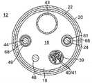
图1是根据一个实施方案的本发明的导管的顶部平面图。Figure 1 is a top plan view of a catheter of the present invention according to one embodiment.
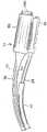
图2A是处于中性无约束构型的图1的导管的3D弧形远侧组件的详细视图。2A is a detailed view of the 3D curved distal assembly of the catheter of FIG. 1 in a neutral unconstrained configuration.
图2B是处于收缩构型的图2的3D弧形远侧组件的详细视图。2B is a detailed view of the 3D arcuate distal assembly of FIG. 2 in a collapsed configuration.
图3是沿线A-A截取的图1的导管的导管主体的端部剖视图。3 is an end cross-sectional view of the catheter body of the catheter of FIG. 1 taken along line A-A.
图4是沿线B-B截取的图1的导管的可偏转中间节段的端部剖视图。4 is an end cross-sectional view of the deflectable intermediate section of the catheter of FIG. 1 taken along line B-B.
图5A是沿线C-C截取的图1的导管的连接器节段的端部剖视图。5A is an end cross-sectional view of the connector section of the catheter of FIG. 1 taken along line C-C.
图5B是沿区域D-D截取的图1的连接器节段的侧面剖视图。5B is a side cross-sectional view of the connector segment of FIG. 1 taken along area D-D.
图6A是支撑构件和共延收缩线以及径向收紧管道的透视图。6A is a perspective view of a support member and coextensive shrink wire and radially constricted tubing.
图6B是图6A的支撑构件和收缩线的远侧端部的装配结构的详细俯视图。6B is a detailed top view of the assembled configuration of the support member and the distal end of the retraction wire of FIG. 6A.
图7是图1的远侧组件的端视图。7 is an end view of the distal assembly of FIG. 1 .
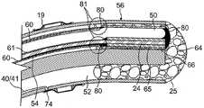
图8是沿线E-E截取的图2A的远侧组件的端部剖视图。8 is an end cross-sectional view of the distal assembly of FIG. 2A taken along line E-E.
图9是沿线F-F截取的图2A的远侧组件的侧面剖视图。9 is a side cross-sectional view of the distal assembly of FIG. 2A taken along line F-F.
图10是根据一个实施方案的具有引导线附接件的冲洗消融电极的透视图。10 is a perspective view of an irrigated ablation electrode with guidewire attachment, according to one embodiment.
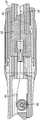
图11是根据一个实施方案的的控制手柄的侧面剖视图。Figure 11 is a side cross-sectional view of a control handle according to one embodiment.
图12是图11的控制手柄的局部俯视剖视图。FIG. 12 is a partial top sectional view of the control handle of FIG. 11 .
图13A是再成形之前的图6的支撑构件的端部剖视图。13A is an end cross-sectional view of the support member of FIG. 6 prior to reshaping.
图13B是沿线G-G截取的图6的支撑构件的端部剖视图。13B is an end cross-sectional view of the support member of FIG. 6 taken along line G-G.
图13C是沿线J-J截取的图6的支撑构件的端部剖视图。13C is an end cross-sectional view of the support member of FIG. 6 taken along line J-J.
具体实施方式Detailed ways
下文描述的本发明的实施方案提供了探头诸如导管,其具有改善的弧形远侧电极承载结构,以便于在心脏中,尤其是在患者身体中的不同尺寸的管状区域和管状区域内的不同周向位置中进行操纵和定位。此类导管可以用于产生大致圆形或螺旋形的消融路径,以及沿大致曲线或螺旋形的图案感测电活动用于电势和解剖标测。Embodiments of the present invention described below provide probes, such as catheters, with an improved arcuate distal electrode-carrying structure to facilitate different sizes of tubular regions and within different tubular regions in the heart, especially in a patient's body. Manipulation and positioning in a circumferential position. Such catheters may be used to create a generally circular or helical ablation path, as well as to sense electrical activity along a generally curved or helical pattern for potential and anatomical mapping.
参见图1,根据所公开的实施方案的导管10包括:细长主体,该细长主体可包括具有纵向轴线13的柔性插入轴或导管主体12;以及在导管主体远侧的中间节段14,中间节段14可以从纵向轴线13单向或双向偏轴偏转。如图2A所示,有回弹力的三维(3D)弧形远侧组件17从中间节段14延伸,远侧组件17有利地被构造成用于显著更大且更均匀的环收缩。如下面进一步详细解释的,远侧组件17响应于操作者操纵控制手柄16而减小其半径并增加其卷绕,如图2B所示。。Referring to FIG. 1 , a catheter 10 according to the disclosed embodiments includes an elongated body, which may include a flexible insertion shaft or
在图1和图3所示的实施方案中,导管主体12包括具有单个轴向或中心管腔18的细长管状构造。导管主体12是柔性的,即可弯曲的,但是沿其长度基本上不可压缩。导管主体12可以具有任何合适的构造并且可以由任何合适的材料制成。在一些实施方案中,构造包括由聚氨酯或PEBAX制成的外壁20。如本领域通常已知的,外壁20包括不锈钢等的嵌入式编织网,以增大导管主体12的扭转刚度,使得当旋转控制手柄16时,中间节段14将以对应的方式旋转。In the embodiment shown in FIGS. 1 and 3 ,
导管主体12的外径并非决定性因素,但在一些实施方案中为不大于约8弗伦奇,更优选地为7弗伦奇。同样,外壁20的厚度也不是决定性因素,但是足够薄,使得中心管腔18可以容纳任何期望的线、缆线和/或管。外壁20的内表面衬有加劲管22,以提供改善的扭转稳定性。加劲管22的外径与外壁20的内径相比大致相同或略小。加劲管22可以由任何合适的材料诸如聚酰亚胺制成,其提供非常好的刚度,并且在体温下不软化。The outer diameter of
可偏转的中间节段14包括具有多个管腔的较短节段的管道23,每个管腔均被来自导管12并且进入中间节段14的各种部件占据。在图4所示的实施方案中,具有六个管腔。耦接到环状电极19,相应的引导线/热电偶对40,41穿过第一管腔31。可提供非导电的护套39以包围线对40/41。用于将冲洗流体递送到远侧组件17的冲洗管道43穿过第二管腔32。为了使中间节段14能够偏转,偏转牵拉线44穿过第三管腔33。包括承载在远侧组件17中的一个或多个单轴传感器(SAS)的位置传感器缆线组件48穿过第四管腔34。为了使得远侧组件17的弧形远侧部分15的形状和尺寸例如曲率半径响应于使用者对控制手柄的操纵可变,收缩线24穿过第六管腔36。如下所述,收缩线24作用于提供远侧组件17的3D形状的形状记忆支撑构件50上。The deflectable
中间节段14的多管腔管道23由优选地比导管主体12更具柔性的合适的无毒材料制成。合适的材料是编织聚氨酯或PEBAX,即具有不锈钢等的嵌入式编织网的聚氨酯或PEBAX。管腔的数量和尺寸不是决定性因素,前提是有足够空间来容纳相关部件。在所示实施方案中,用于偏转牵拉线44和收缩线24的第三管腔和第六管腔33和36是偏轴的且彼此沿直径相对,并且用于支撑构件50的第五管腔35在轴线上。The
导管的可用长度即除远侧组件17以外可以插入体内的部分可以根据需要变化。优选地,可用长度在约110cm至约120cm的范围内。中间节段14的长度是可用长度的相对小的部分,并且优选地在约3.5cm至约10cm的范围内,更优选地在约5cm至约6.5cm的范围内。The usable length of the catheter, ie the portion that can be inserted into the body other than the
远侧组件17在中间节段14的远侧。如图2A和图5A所示,大致直的连接器节段30在中间节段14和远侧组件17之间延伸,连接器节段30具有适当材料例如PEEK的管道,该管道具有中心管腔37,中心管腔37允许在中间节段14和远侧组件17之间延伸的各种部件根据需要重新取向和重新定位,以在中间节段14和远侧组件17之间过渡,如图5B所示。部件通过合适的粘合剂112封装在节段30的管腔37中。支撑远侧组件17并提供其3D维度形状,形状记忆支撑构件50从远侧组件17朝近侧延伸相对短的距离进入连接器节段30的远侧部分。
如图2A和图6所示,3D远侧组件17包括预成形的弧形远侧部分15、弯管部分21以及近侧线性杆26。弧形远侧部分15承载多个冲洗环形电极19。弯管部分21被配置成使远侧部分15相对于纵向轴线13倾斜地取向,使得纵向轴线大致延伸通过远侧部分15的中心,如图7所示。由此,倾斜角θ(图2A)被限定在纵向轴线13和大致由远侧组件17限定的平面P之间,其中倾斜角θ的范围在约45度和135度之间,优选地约75度和100度之间,并且优选地为约90度。As shown in FIGS. 2A and 6 , the 3D
参考图2A、图6和图7,弯管部分21具有近侧弯曲节段21P、弯管接合部或“扭转部”42以及远侧弯曲节段21D。近侧弯曲节段21P描绘由第一(或近侧)半径R1相对于纵向轴线13限定的第一弧线。远侧弯曲节段21D描绘由第二(或中间)半径R2相对于倾斜于纵向轴线13的轴线27限定的第二弧线。第一半径R1小于第二半径R2。然而,半径R1和R2二者均小于限定由远侧部分15描绘的第三弧线的第三(或远侧)半径R3。在一些实施方案中,半径R1的范围在约0.1″和0.25″之间,半径R2的范围在约0.15″和0.38″之间,并且半径R3的范围在约0.4″和0.6″之间。由此,当无约束时,远侧组件17的3D构型具有螺线特性,其中半径R3大于半径R2。例如,在倾斜角θ约为90度且纵向轴线13限定Z轴的情况下,由半径R1限定的第一弧可位于Y/Z平面中,并且分别由半径R2和半径R3限定的第二弧和第三弧可二者均位于X/Y平面中,如图6所示。应当理解,远侧组件17不限于上述的半径R1,R2和R3,并且可根据需要或期望包含更多或更少的半径。Referring to FIGS. 2A , 6 and 7 , the elbow portion 21 has a proximal
当无约束时,远侧组件17的3D构型也具有螺旋特性,因为远侧组件17在其成螺线形时朝远侧延伸,使得远侧组件17的远侧端部25是远侧组件17的最远侧部分,如图2A中最佳所示。When unconstrained, the 3D configuration of the
因此,远侧组件17具有螺线-螺旋形构型(或螺旋-螺线形构型),使得远侧端部25和远侧弯曲节段21D之间存在沿纵向轴线13的第一分离间隙,并且在远侧端部25和远侧弯曲节段21D之间存在沿倾斜轴线27的第二分离间隙。远侧组件17的螺线-螺旋形构型可以被描述为从其近侧端部到其远侧端部描绘放大的螺旋,该放大的螺旋与纵向轴线一致,如图2A所示。Accordingly,
根据远侧部分15的长度,处于其中性无约束的3D构型的远侧组件17可在扭转部42和远侧端部25之间对向约360度的径向角α。在另一个实施方案中,远侧组件17对向大于360度,例如约380度的径向角α(图6)。如图2B所示,当远侧组件17收缩时,螺线-螺旋形式“卷起”并绷紧,其中远侧组件17所描绘的一个或多个半径R1、R2、R3减小,并且远侧组件17在扭转部42和远侧端部25之间对向的径向角α从例如约360度或380度增加到约540度或更大。因此,处于其中性无约束构型的远侧组件17可用于与具有较大半径的口进行周向接触,并且然后被调节到其收缩构型,用于在具有显著较小半径的口的PV内进行周向接触。Depending on the length of the
如图8所示,远侧组件17包括多管腔管道56。在所公开的实施方案中,管道56具有四个偏轴管腔,即,用于SAS缆线组件48的第一管腔51(被摩擦减小涂层38例如
在所示实施方案中,远侧组件17的预成形支撑构件50延伸通过管道56的第四管腔54,以提供并且限定远侧组件17的3D螺线-螺旋形状,该3D螺线-螺旋形状包括扭转部42和近侧节段21P与远侧节段21D的弧,以及由半径R1,R2和R3限定的远侧部分15。支撑构件50由具有形状记忆(即在施加力时可从其初始形状变直或弯曲并能够在移除该力后基本恢复至其初始形状)的材料制成。在一些实施方案中,适用于支撑构件50的材料是镍/钛合金。此类合金通常包括约55%的镍和45%的钛,但也可包含约54%至约57%的镍,剩余为钛。一种镍/钛合金为具有优异的形状记忆性以及延展性、强度、耐腐蚀性、电阻率和温度稳定性的镍钛诺。In the illustrated embodiment, the preformed
在一些实施方案中,如图5A所示,支撑构件50具有接收并附连在连接器节段30中的近侧端部。在一些实施方案中,近侧端部在连接器节段30的远侧端部近侧延伸约2mm-3mm的深度。另选地,支撑构件50可以根据需要或适当地进一步朝近侧延伸到中间节段14的管腔35中,通过中间节段14的整个长度,甚至经由中心管腔18进入导管主体12。In some embodiments, as shown in FIG. 5A ,
有利地,支撑构件50具有大致矩形的横截面形状,该矩形横截面形状的高度和宽度尺寸沿构件50的长度以预定的方式变化。如图13B和图13C所示,沿长度的任何位置处的大致矩形的横截面积保持恒定,但其宽度尺寸W和高度尺寸在不同位置处变化。沿长度的任何位置处的横截面积没有减少或增加,因为在一个尺寸上的任何损失或增加由沿支撑构件50的长度的在更近侧位置和更远侧位置之间的另一个尺寸成比例地增加或损失。当支撑构件50的渐缩部分或“尾部”从构件的近侧端部到远侧端部在横截面积的一个尺寸上变窄时,横截面积的另一尺寸从近侧端部到远侧端部变宽。减小的尺寸(例如,图13B和图13C中的沿X轴的宽度尺寸W)降低其从近侧端部到远侧端部在该尺寸上的抗弯曲性,而增加的尺寸(例如,图13B和图13C中的沿Y轴的高度尺寸H)增加其从渐缩部分的近侧端部到远侧端部在该尺寸上的抗弯曲性。Advantageously, the
如图6所示,支撑构件50在其近侧端部处的大致矩形的横截面具有最大宽度W1和最小高度H1。为了最小化半径R1和半径R2在远侧组件17收缩期间的变化或变形,支撑构件50的横截面积的宽度尺寸和高度尺寸开始在半径R2的远侧的预定位置处开始改变(或渐缩)(例如,在位置L2处或附近)。在预定位置的远侧,在远侧组件17的渐缩尾部中,当高度开始增加到H2(>H1)时,宽度开始减小到W2(<W1)。当远侧位置L3处的高度进一步增加到H3(>H2>H1)时,宽度进一步减小到W3(<W2<W1)。这些减小和增加是平稳和连续的。这种该渐缩构型偏置支撑构件50,以诸如当由收缩线24收缩时具有越来越小的抵抗朝向远侧端部25卷绕的阻力,同时诸如当远侧组件17迎面接触组织表面时提供越来越大的抵抗朝向远侧端部25的倾斜力的阻力。因此,该变化的横截面形状允许远侧组件17表现出改善的收缩特性,包括远侧部分15能够容易地收缩和卷绕,其中弯管接合部21的变形最小并且弯管接合部21能够更好地承受来自当远侧组件17与目标组织接触时施加的轴向力的负载。利用应用于支撑构件50的这种变化的横截面形状,当致动收缩线24时,远侧组件17可以被调节为呈现较小的环尺寸(参见图2B),例如,其中远侧部分15呈现大致等于或甚至小于远侧节段21D的曲率的曲率。As shown in FIG. 6 , the generally rectangular cross-section of
如图6所示,在具有大致矩形横截面的情况下,支撑构件50类似于具有限定大致矩形横截面的高度尺寸的侧面/表面62和63,以及限定大致矩形横截面的宽度尺寸的边缘75的“卷绕带状物”。有利地,内扁平侧/表面62沿其长度连续地面向远侧组件的螺线-螺旋形构型的内圆周,并且与内扁平表面62相对的外扁平侧/表面63连续地面向外侧,远离螺线-螺旋形构型的内圆周。支撑构件50的渐缩导致远侧组件17的“渐缩尾部”类似于越来越宽且越来越薄的带状物。As shown in FIG. 6 , having a generally rectangular cross-section,
此外,支撑构件50的近侧端部处的大致矩形横截面有助于将近侧端部锚固在可偏转节段14的管道23的管腔35中,并降低支撑构件围绕其轴线旋转的风险,其中近侧端部通过粘合剂例如环氧树脂封装(参见图4)。Furthermore, the generally rectangular cross-section at the proximal end of the
在一些实施方案中,支撑构件50以圆形横截面形状开始,如图13A所示。支撑构件50例如圆形线逐渐变平以产生大致矩形的横截面和渐缩的尾部。因此,具有高度尺寸的平行扁平化表面之间的具有宽度尺寸的两个相对端部承载原始圆形横截面形状的残余圆形形状。应当理解,支撑构件可以正方形/矩形横截面形状开始,其然后将导致扁平的相对端部而不是圆形的相对端部。在一些实施方案中,使用圆形线可更加经济地制造,并且圆形的相对端部可使远侧组件17容易地装配,包括将支撑构件插入到径向收紧的柔性管道或套筒60中,如下面进一步讨论的。圆形的相对端部可减小用于将支撑构件50插入到管道60中的插入力,并且还可降低支撑构件50撕裂和损坏管道60的风险。In some embodiments, the
在一些实施方案中,作为圆形线的支撑构件50具有约0.019英寸的初始(预扁平化)直径和约4.25英寸的长度。当扁平化时,支撑构件50具有从其近侧端部到位置L2的约0.021″×0.015″的大致矩形横截面尺寸。支撑构件50的渐缩尾部(在图6中位置L2的远侧)长约2.9英寸,并且在其远侧端部25处或其附近具有约0.035″×0.008"的大致矩形横截面尺寸。在一些实施方案中,支撑构件50的远侧端部具有保持其圆形横截面的未扁平化节段50D,如下面更详细地解释的。In some embodiments,
无论质量中心轴线的取向如何,0.019英寸直径的支撑构件50的面积惯性矩(预扁平化)都是相同的,而对于第一质量中心轴线而言,在支撑构件50远侧端部处或其附近的面积惯性矩比在近侧端部处的惯性矩的刚度小2.5倍。第二质量中心轴线的在远侧端部处的惯性矩比在近侧端部处的惯性矩的刚度大4.5倍。将远侧端部处的两个质量中心轴线面积惯性矩彼此比较,第一质量中心轴线的刚度比第二质量中心轴线小18.5倍。由于收缩线24在支撑构件50上施加恒定的向内的力线(忽略摩擦),因此为了获得小的大致圆形的收缩,支撑构件50的面积惯性矩应当朝向其附接到收缩线24的远侧端部持续地减小。The area moment of inertia (pre-flattened) of the 0.019 inch
收缩线24具有锚固在控制手柄16中的近侧端部,近侧端部提供用于经由操作者的操纵来致动收缩线24的旋转控制旋钮59(参见图1)。收缩线24通过导管主体12的中心管腔18(图3)、中间节段14的第六管腔36(图4)、连接器节段30的中心管腔37(图5A)以及与支撑构件50并排的远侧组件17的管道56的第四管腔54(图8)延伸到远侧端部25(图9)。The
收缩线24可由摩擦减小管道61(图8),例如聚酰亚胺或PEEK管道的
有利地,穿过远侧组件17的管腔54的支撑构件50以及收缩线24(及其管道61)的共延区段被紧密配合的柔性管道60包围并绑在一起,如图6所示。在一些实施方案中,紧密配合管道60具有由摩擦减小材料诸如
如图6所示,收缩线24在其管道61内沿在远侧组件17的远侧端部25与连接器节段30之间延伸的支撑构件50的面向内的侧面62的整个长度延伸。当收缩线24被朝近侧拉动时,该预定图案有利地使收缩线24从支撑构件50分离并抬升的任何趋势最小化。在一些实施方案中,收缩线24还可具有沿其长度或沿其一个或多个区段的矩形横截面。As shown in FIG. 6 , the
参考图8和图9,支撑构件50、收缩线24和收紧管道60的远侧端部的装配结构在远侧组件17的管道56的第四管腔54内取向,使得收缩线24与远侧组件17的内圆周最邻近以面向远侧组件17的中心。在第四管腔54定位成比管道56的其它管腔更靠近内圆周,并且管腔54内的收缩线24也定位成比支撑构件50更靠近内圆周的情况下,收缩线24可以有效地收缩远侧组件17。8 and 9, the assembly of
在插入到管腔54中之前,准备支撑构件50、收缩线24和收紧管道60的远侧端部的组装结构。在一些实施方案中,收缩线24和支撑构件50的远侧端部的耦接包括具有放置在支撑构件50的远侧端部25D上的(例如,304或316系列的)不锈钢套圈65的激光焊接耦接,支撑构件50的远侧端部25D未被扁平化而是保留其原始的圆形横截面形状。套圈65在其被放置在远侧端部25D上之后变平。支撑构件50的扁平部分用作止挡件,当收缩线张力施加到支撑构件50时该止挡件防止套圈65的任何朝近侧的迁移或错位。套圈65通过具有平行于支撑构件50的表面62的扁平部分的压接模具固定到支撑构件50的圆形远侧端部50D。收缩线24的远侧端部具有压接套圈80,压接套圈80具有扁平部分,该扁平部分也被固定到套圈65的扁平部分。激光缝焊101形成在套圈65和80的一个公共(底部)侧面上,从而接合收缩线24和支撑构件50的远侧端部。Prior to insertion into
与使用无铅焊料将镍钛诺支撑构件接合到收缩线的支撑构件和收缩线的现有技术耦接相反,本文所述的激光焊接耦接包括使用强酸性焊剂以在焊接之前从镍钛诺和不锈钢去除氧化物。此外,与现有技术的具有低剪切和低拉伸强度(大约4000psi)的无铅焊料相比,激光焊接耦接提供强得多的附接,其中低剪切和低拉伸强度可以归因于当无铅焊料包含未暴露的空隙或形成为冷焊点时来自镍钛诺支撑构件的牵拉线脱离故障。In contrast to prior art couplings of the support member and the shrink wire that use lead-free solder to bond the nitinol support member to the shrink wire, the laser soldered coupling described herein involves the use of a strong acid flux to and stainless steel to remove oxides. In addition, laser solder coupling provides a much stronger attachment than prior art lead-free solders with low shear and low tensile strength (approximately 4000 psi), which can be attributed to Failure due to pull wire detachment from the Nitinol support member when the lead-free solder contains unexposed voids or forms a cold solder joint.
然后,收紧管道60在其近侧端部处滑过收缩线24,在其近侧端部处在支撑构件50上推进,并进一步推进直到管道60的远侧端部到达并覆盖装配结构。The cinching
当收紧管道60已经被适当地定位在收缩线24和支撑构件50上时,收紧管道60具有靠近半径R2和R3的接合部的近侧端部,并且其远侧端部被修剪或以其它方式设置有紧接着在不锈钢套圈65的近侧终止的完成的远侧端部。然后,通过周向施加粘合剂111例如
然后将收缩线24、支撑构件50和收紧管道60的装配结构插入到管腔54中,其中不锈钢套圈65及其所包含的部件通过粘合剂64例如聚氨酯被固定和锚固在多管腔管道56的远侧端部处,其中粘合剂64覆盖远侧端部25的整个远侧面以形成末端圆顶,如图9所示。采用该布置,可以控制收缩线24和支撑构件50的相对位置,使得收缩线24如上所述定位在远侧组件17的内圆周上或附近,更靠近螺线-螺旋形式的中心。收紧管道60保护多管腔管道56在远侧组件17收缩期间免受收缩线24切入到其侧壁中的影响。The assembly of
参考图3和图4,包围收缩线24的压缩线圈68从导管主体12的近侧端部延伸并通过中间节段14的第六管腔36的整个长度。因此,压缩线圈具有在连接器节段30中的中间位置处或附近的远侧端部。压缩线圈68由任何合适的金属优选地为不锈钢制成,并且紧密缠绕在其自身上以提供柔性,即弯曲,但是抵抗压缩。压缩线圈的内径优选地略大于收缩线24的直径。压缩线圈的外表面被(例如由聚酰亚胺管道制成的)柔性的非导电护套67覆盖。压缩线圈优选地由具有正方形或矩形横截面积的线形成,这使得其可压缩性比由具有圆形横截面积的线形成的压缩线圈的可压缩性差。因此,压缩线圈68可防止导管主体12尤其是中间节段14在朝近侧拉动收缩线24以使远侧组件17收缩时发生偏转,因为压缩线圈68可吸收更多的压缩。Referring to FIGS. 3 and 4 , the
环形电极19安装在远侧部分15上的预定位置上,如图2A和图2B所示。电极可以由任何合适的固体导电材料制成,诸如铂或金,优选地为铂和铱或金和铂的组合,并且可以用胶等将电极安装到管道上。适于消融和冲洗的电极的合适的实施方案示于图10中。消融贮存器(“AR”)电极为长度大于其直径的大致圆柱形的。在一个实施方案中,长度为约3.0mm,外径为约2.8mm,内径为约2.33mm。The
在一些实施方案中,远侧组件17上的多个AR环形电极19可以在从约六至约二十的范围内,更优选地从约八至约十二的范围内。在一些实施方案中,远侧组件17承载十个AR电极。电极可以沿远侧部分15大致均匀地间隔开。In some embodiments, the plurality of
线对40,41的每根线的近侧端部电连接到在控制手柄16远侧的合适的连接器(未示出)。在所公开的实施方案中,线对的线40是铜线,例如数字“40”的铜线,而线对的另一根线41是康铜线。线对从控制手柄16延伸,通过导管主体12的中心管腔18(图3)、中间节段14的第一管腔31(图4)、连接器节段30的中心管腔37(图5A)和远侧组件17的第二管腔52(图8)。线对的远侧端部穿过形成在管道56的侧壁中的孔74(图9)以到达AR电极19。除了在线被暴露的远侧端部处之外,每对线是彼此电绝缘的。将相应的线对40,41的暴露的远侧端部喷砂,并包裹在折叠的金属箔72(例如,铜箔)中并且焊接到其上,然后将折叠的金属箔72焊接到其AR电极19的近侧端部71附近的内表面70,如图10所示。The proximal end of each wire of the wire pair 40 , 41 is electrically connected to a suitable connector (not shown) distal to the control handle 16 . In the disclosed embodiment, the wire 40 of the pair is a copper wire, such as the numeral "40", and the other wire 41 of the pair is a constantan wire. The wire pair extends from the control handle 16 through the
消融能量例如射频能量经由线对的线40递送到AR电极19。然而,包括它们相应的康铜线41的线对还可以用作感测每个AR电极19的温度的温度传感器或热电偶。Ablation energy, such as radio frequency energy, is delivered to the
所有线对均穿过一个非导电保护套39(图3和图4),该保护套39可以由与其成包围关系的任何合适的材料例如聚酰亚胺制成。护套39与线对一起从控制手柄16、导管主体12、中间节段14、连接器节段30延伸并且延伸到远侧组件17的第二管腔52中,例如延伸到第二管腔52中约5mm,终止于连接器节段30和远侧组件17之间的接合部的远侧。远侧端部通过胶例如聚氨酯胶等锚固在第二管腔52中。All wire pairs pass through a non-conductive protective sheath 39 (Figs. 3 and 4) which may be made of any suitable material such as polyimide in enclosing relationship therewith. The
冲洗流体由冲洗管道43递送到远侧组件,该冲洗管道的近侧端部附接到在控制手柄16近侧的鲁尔毂73(图1)并且接收由泵(未示出)递送的流体。冲洗管道43延伸通过控制手柄16、导管主体12的中心管腔18(图3)、中间节段14的第二管腔32(图4)、连接器节段30的中心管腔37(图5A),以及朝远侧延伸进入远侧组件17的多管腔管道56的第三管腔53中短的距离,例如约5mm。流体进入第三管腔53,其中流体经由形成在管道56的侧壁中的开口(未示出)离开,以进入AR环形电极19并且离开形成在电极侧壁中的开孔78(图10)。应当理解,远侧部分15可根据需要或适当地承载任何形式的电极,包括上述AR环形电极、阻抗环形电极和/或其组合。Irrigation fluid is delivered to the distal assembly by
偏转牵拉线44被设置用于中间轴14的偏转。偏转线44延伸通过导管主体12的中心管腔18(图3)和中间节段14的第三管腔33(图4)。偏转线在其近侧端部处锚固在控制手柄16中,并且在其远侧端部处通过T形棒76(图4)锚固到在中间节段14的远侧端部处或其附近的位置,该T形杆76通过合适的材料例如聚氨酯69附连到管道15的侧壁。牵拉线54由任何合适的金属诸如不锈钢或镍钛诺制成,并且优选地涂覆有
第二压缩线圈47位于与牵拉线44呈包围关系的导管主体12的中心管腔18内(图3)。第二压缩线圈47从导管主体12的近侧端部延伸到中间节段14的近侧端部处或其附近。第二压缩线圈47由任何合适的金属优选地为不锈钢制成,并且紧密缠绕在其自身上以提供柔性,即弯曲,但是抵抗压缩。第二压缩线圈47的内径优选地略大于牵拉线44的直径。牵拉线上的
在中间节段14的第三管腔33内,牵拉线44延伸通过优选地为
使得远侧组件17的螺线-螺旋形式收缩的收缩线24相对于导管主体12的纵向运动通过控制手柄16的适当操纵完成。类似地,使得中间节段14偏转的偏转线44相对于导管主体12的纵向运动通过控制手柄16的适当操纵完成。用于操纵多于一根线的合适的控制手柄在以下专利中有所描述:例如,美国专利号6,468,260,6,500,167和6,522,933,所述专利的全部公开内容以引用方式并入本文。Longitudinal movement of the
在一个实施方案中,导管包括控制手柄16,如图11和图12中所示。控制手柄16包括偏转控制组件,该偏转控制组件具有手柄主体84,其中芯86固定安装在该手柄主体84中并且活塞87可滑动地安装在芯86的远侧区域上。活塞87具有延伸到手柄主体外侧的远侧部分。拇指旋钮58被安装在远侧部分上,使得使用者可以更容易地使活塞87相对于芯86和手柄主体84纵向运动。导管主体12的近侧端部被固定安装到活塞87的远侧端部。轴向通道88被设置在活塞87的远侧端部处,使得包括延伸通过导管主体12的引导线40,41,收缩线24,偏转线44,位置传感器缆线组件48和冲洗管道43的多个部件均可以进入控制手柄。引导线40,41可以延伸出控制手柄16的近侧端部,或者可以连接到结合到控制手柄中的连接器,如在本领域中众所周知的。冲洗管道43也可以延伸出控制器16的近侧端部,以经由鲁尔毂与冲洗源(未示出)连接。In one embodiment, the catheter includes a
偏转线44的近侧端部进入控制手柄16,并且围绕滑轮83被包裹且被锚固到芯86。拇指旋钮58和活塞87相对于手柄主体84和芯86朝远侧的纵向运动朝远侧拉动偏转线44的近侧端部。因此,在锚固偏转线44的中间节段14的一侧牵拉偏转线,从而在该方向上偏转中间节段。为了释放并拉直中间节段14,拇指旋钮58向近侧移动,这使得活塞87相对于手柄主体84和芯86朝近侧移动回到其初始位置。The proximal end of
控制手柄16还用于经由旋转控制组件来使收缩线24纵向运动。在所示实施方案中,旋转控制组件包括凸轮手柄81和凸轮接收器82。通过在一个方向上旋转凸轮手柄,凸轮接收器朝近侧被拉动,以拉动收缩线24。通过在另一个方向上旋转凸轮手柄,凸轮接收器朝远侧推进以释放收缩线24。收缩线24通过活塞88中的轴向通道并且通过芯86从导管主体12延伸到控制手柄16中,以被锚固在调节器85中,可以通过该调节器85来调节收缩线上的张力。The control handle 16 is also used to move the
在一个实施方案中,包括多个单轴传感器(“SAS”)的位置传感器缆线组件48延伸通过远侧组件17的第一管腔51(图8),其中每个SAS占据远侧组件17的螺线-螺旋形式上的已知或预定位置。缆线组件48从远侧组件17朝近侧延伸通过连接器节段30的中心管腔37、中间节段14的第四管腔34(图4)、导管主体12的中心管腔18(图3)并且进入控制手柄16。每个SAS可定位成具有分离相邻SAS的已知并相等的间距。在本发明所公开的实施方案中,缆线承载三个SAS,这三个SAS被定位在最远侧AR电极、最近侧AR电极以及中间AR电极的下方,用于感测远侧组件17的定位和/或位置。SAS使得螺线-螺旋形式能够在由BiosenseWebster,Inc.制造并销售的标测系统下查看,该标测系统包括CARTO、CARTO XP和NOGA标测系统。合适的SAS在美国专利号8,792,962中有所描述,该专利的全部公开内容以引用方式并入本文。In one embodiment, a position
已参考本发明的当前优选实施方案来呈现前述描述。本发明所属技术领域内的技术人员将认识到,在未有意脱离本发明的原则、实质和范围的前提下,可对所描述的结构作出变更和更改。在一个实施方案中公开的任何特征或结构可根据需要或适当情况并入以代替或补充任何其它实施方案的其它特征。如本领域的普通技术人员所理解的,附图未必按比例绘制。因此,上述描述不应视为仅与附图中描述和例示的精确结构有关,而应视为符合以下具有最全面和合理范围的权利要求书并且作为权利要求书的支持。The foregoing description has been presented with reference to presently preferred embodiments of the invention. Those skilled in the art to which this invention pertains will recognize that changes and modifications can be made in the described structures without intentionally departing from the principle, spirit and scope of this invention. Any feature or structure disclosed in one embodiment may be incorporated as desired or appropriate in place of or in addition to other features of any other embodiment. As understood by those of ordinary skill in the art, the drawings are not necessarily drawn to scale. Accordingly, the foregoing description should not be read as pertaining only to the precise structures described and illustrated in the drawings, but should be read in accordance with, and as support for, the following claims, having their fullest and reasonable scope.
Claims (5)
Translated fromChinesePriority Applications (2)
| Application Number | Priority Date | Filing Date | Title |
|---|---|---|---|
| CN202210902333.8ACN115281820A (en) | 2016-12-28 | 2017-12-28 | Catheter with tapered support member for variable arc distal assembly |
| CN202210902472.0ACN115281821A (en) | 2016-12-28 | 2017-12-28 | Catheter with tapered support member for variable arc distal assembly |
Applications Claiming Priority (2)
| Application Number | Priority Date | Filing Date | Title |
|---|---|---|---|
| US15/393155 | 2016-12-28 | ||
| US15/393,155US10828091B2 (en) | 2016-12-28 | 2016-12-28 | Catheter with tapered support member for variable arcuate distal assembly |
Related Child Applications (2)
| Application Number | Title | Priority Date | Filing Date |
|---|---|---|---|
| CN202210902333.8ADivisionCN115281820A (en) | 2016-12-28 | 2017-12-28 | Catheter with tapered support member for variable arc distal assembly |
| CN202210902472.0ADivisionCN115281821A (en) | 2016-12-28 | 2017-12-28 | Catheter with tapered support member for variable arc distal assembly |
Publications (2)
| Publication Number | Publication Date |
|---|---|
| CN108245247A CN108245247A (en) | 2018-07-06 |
| CN108245247Btrue CN108245247B (en) | 2022-10-28 |
Family
ID=60813685
Family Applications (3)
| Application Number | Title | Priority Date | Filing Date |
|---|---|---|---|
| CN201711467173.4AActiveCN108245247B (en) | 2016-12-28 | 2017-12-28 | Catheter with tapered support member for variable arc distal assembly |
| CN202210902472.0APendingCN115281821A (en) | 2016-12-28 | 2017-12-28 | Catheter with tapered support member for variable arc distal assembly |
| CN202210902333.8APendingCN115281820A (en) | 2016-12-28 | 2017-12-28 | Catheter with tapered support member for variable arc distal assembly |
Family Applications After (2)
| Application Number | Title | Priority Date | Filing Date |
|---|---|---|---|
| CN202210902472.0APendingCN115281821A (en) | 2016-12-28 | 2017-12-28 | Catheter with tapered support member for variable arc distal assembly |
| CN202210902333.8APendingCN115281820A (en) | 2016-12-28 | 2017-12-28 | Catheter with tapered support member for variable arc distal assembly |
Country Status (7)
| Country | Link |
|---|---|
| US (3) | US10828091B2 (en) |
| EP (2) | EP3656330B1 (en) |
| JP (3) | JP7171187B2 (en) |
| CN (3) | CN108245247B (en) |
| AU (1) | AU2017268689A1 (en) |
| CA (1) | CA2989348A1 (en) |
| IL (1) | IL255893B (en) |
Families Citing this family (10)
| Publication number | Priority date | Publication date | Assignee | Title |
|---|---|---|---|---|
| US10828091B2 (en) | 2016-12-28 | 2020-11-10 | Biosense Webster (Israel) Ltd. | Catheter with tapered support member for variable arcuate distal assembly |
| US10918832B2 (en) | 2017-03-27 | 2021-02-16 | Biosense Webster (Israel) Ltd | Catheter with improved loop contraction and greater contraction displacement |
| CN110215547B (en)* | 2019-06-15 | 2021-08-24 | 南阳市中心医院 | Malignant ascites puncture drainage device |
| US12220541B2 (en)* | 2019-07-03 | 2025-02-11 | Biosense Webster (Israel) Ltd. | Sensing and mapping catheter for guiding and supporting balloon catheter |
| EP4021563B1 (en)* | 2019-08-29 | 2024-12-04 | Cochlear Limited | Implantable carrier with embedded stabilizer |
| EP3972511B1 (en)* | 2019-09-19 | 2023-03-08 | St. Jude Medical, Cardiology Division, Inc. | Electrode loop assembly including shaped support tube and method of assembling same |
| US20230058649A1 (en)* | 2021-08-17 | 2023-02-23 | Biosense Webster (Israel) Ltd. | Sheath, catheter, and method of controlling radial orientation thereof |
| CN114533258A (en)* | 2022-03-17 | 2022-05-27 | 无锡帕母医疗技术有限公司 | Radio frequency ablation catheter |
| US20230380892A1 (en)* | 2022-05-27 | 2023-11-30 | Prothia S.A.R.L. | Lead and medical use thereof |
| EP4349287A1 (en)* | 2022-10-07 | 2024-04-10 | Erbe Elektromedizin GmbH | Ablation instrument |
Citations (1)
| Publication number | Priority date | Publication date | Assignee | Title |
|---|---|---|---|---|
| CN102846374A (en)* | 2011-06-30 | 2013-01-02 | 韦伯斯特生物官能(以色列)有限公司 | Catheter with variable arcuate distal section |
Family Cites Families (35)
| Publication number | Priority date | Publication date | Assignee | Title |
|---|---|---|---|---|
| US5820591A (en) | 1990-02-02 | 1998-10-13 | E. P. Technologies, Inc. | Assemblies for creating compound curves in distal catheter regions |
| US6413234B1 (en) | 1990-02-02 | 2002-07-02 | Ep Technologies, Inc. | Assemblies for creating compound curves in distal catheter regions |
| WO1992020290A1 (en) | 1991-05-17 | 1992-11-26 | Innerdyne Medical, Inc. | Method and device for thermal ablation |
| US6071274A (en) | 1996-12-19 | 2000-06-06 | Ep Technologies, Inc. | Loop structures for supporting multiple electrode elements |
| WO1999006095A2 (en) | 1997-07-29 | 1999-02-11 | Ep Technologies, Inc. | Improved catheter distal end assemblies |
| US6004280A (en) | 1997-08-05 | 1999-12-21 | Cordis Corporation | Guiding sheath having three-dimensional distal end |
| US6123699A (en) | 1997-09-05 | 2000-09-26 | Cordis Webster, Inc. | Omni-directional steerable catheter |
| JP2002501769A (en)* | 1997-10-30 | 2002-01-22 | イー.ピー. テクノロジーズ, インコーポレイテッド | Catheter distal assembly with pull wire |
| US6064902A (en) | 1998-04-16 | 2000-05-16 | C.R. Bard, Inc. | Pulmonary vein ablation catheter |
| US20050010095A1 (en) | 1999-04-05 | 2005-01-13 | Medtronic, Inc. | Multi-purpose catheter apparatus and method of use |
| US6468260B1 (en) | 1999-05-07 | 2002-10-22 | Biosense Webster, Inc. | Single gear drive bidirectional control handle for steerable catheter |
| US6745080B2 (en)* | 1999-11-22 | 2004-06-01 | Scimed Life Systems, Inc. | Helical and pre-oriented loop structures for supporting diagnostic and therapeutic elements in contact with body tissue |
| US6648874B2 (en) | 2000-02-28 | 2003-11-18 | Scimed Life Systems, Inc. | Guide catheter with lubricious inner liner |
| US6522933B2 (en) | 2001-03-30 | 2003-02-18 | Biosense, Webster, Inc. | Steerable catheter with a control handle having a pulley mechanism |
| US7175734B2 (en) | 2001-05-03 | 2007-02-13 | Medtronic, Inc. | Porous medical catheter and methods of manufacture |
| US7037290B2 (en) | 2002-12-16 | 2006-05-02 | Medtronic, Inc. | Multi-lumen steerable catheter |
| US7142903B2 (en)* | 2003-03-12 | 2006-11-28 | Biosense Webster, Inc. | Catheter with contractable mapping assembly |
| US20040181208A1 (en) | 2003-03-14 | 2004-09-16 | Poole Matthew S. | Catheter reinforced with high yield strength wire |
| US6973339B2 (en) | 2003-07-29 | 2005-12-06 | Biosense, Inc | Lasso for pulmonary vein mapping and ablation |
| ES2552252T3 (en) | 2004-03-23 | 2015-11-26 | Boston Scientific Limited | Live View System |
| US7662150B2 (en) | 2005-04-27 | 2010-02-16 | Boston Scientific Scimed, Inc. | Variable size apparatus for supporting diagnostic and/or therapeutic elements in contact with tissue |
| US20070270679A1 (en) | 2006-05-17 | 2007-11-22 | Duy Nguyen | Deflectable variable radius catheters |
| US8608735B2 (en) | 2009-12-30 | 2013-12-17 | Biosense Webster (Israel) Ltd. | Catheter with arcuate end section |
| KR101912960B1 (en) | 2010-10-25 | 2018-10-29 | 메드트로닉 아르디언 룩셈부르크 에스에이알엘 | Catheter Appratuses having Multi-Electrode Arrays for Renal Neuromodulation and Associated Systems and Methods |
| EP2613723B1 (en) | 2010-11-19 | 2017-10-25 | St. Jude Medical Atrial Fibrillation Division Inc. | Electrode catheter device with indifferent electrode for direct current tissue therapies |
| US8792962B2 (en) | 2010-12-30 | 2014-07-29 | Biosense Webster, Inc. | Catheter with single axial sensors |
| US8460237B2 (en) | 2011-11-10 | 2013-06-11 | Biosense Webster (Israel), Ltd. | Medical device control handle with multiplying linear motion |
| US9162036B2 (en) | 2011-12-30 | 2015-10-20 | Biosense Webster (Israel), Ltd. | Medical device control handle with multiple puller wires |
| US9433752B2 (en)* | 2012-11-14 | 2016-09-06 | Biosense Webster (Israel) Ltd. | Catheter with flat beam deflection in tip |
| US9433464B2 (en) | 2013-03-14 | 2016-09-06 | Biosense Webster (Israel) Ltd. | Catheter with needles for ablating tissue layers in vessel |
| US9216057B2 (en)* | 2013-03-15 | 2015-12-22 | Kyphon Sarl | Steerable catheter system and method of using a steerable catheter system to dissect and evacuate tissue |
| JP6235428B2 (en) | 2014-07-29 | 2017-11-22 | 朝日インテック株式会社 | catheter |
| US9788893B2 (en) | 2014-11-20 | 2017-10-17 | Biosense Webster (Israel) Ltd. | Catheter with soft distal tip for mapping and ablating tubular region |
| US11628009B2 (en) | 2014-12-17 | 2023-04-18 | Biosense Webster (Israel) Ltd. | EP catheter with trained support member, and related methods |
| US10828091B2 (en) | 2016-12-28 | 2020-11-10 | Biosense Webster (Israel) Ltd. | Catheter with tapered support member for variable arcuate distal assembly |
- 2016
- 2016-12-28USUS15/393,155patent/US10828091B2/enactiveActive
- 2017
- 2017-11-22ILIL255893Apatent/IL255893B/enactiveIP Right Grant
- 2017-12-04AUAU2017268689Apatent/AU2017268689A1/ennot_activeAbandoned
- 2017-12-15CACA2989348Apatent/CA2989348A1/ennot_activeAbandoned
- 2017-12-27EPEP20151234.0Apatent/EP3656330B1/enactiveActive
- 2017-12-27JPJP2017250665Apatent/JP7171187B2/enactiveActive
- 2017-12-27EPEP17210699.9Apatent/EP3342364B1/enactiveActive
- 2017-12-28CNCN201711467173.4Apatent/CN108245247B/enactiveActive
- 2017-12-28CNCN202210902472.0Apatent/CN115281821A/enactivePending
- 2017-12-28CNCN202210902333.8Apatent/CN115281820A/enactivePending
- 2020
- 2020-11-05USUS17/090,760patent/US11925410B2/enactiveActive
- 2022
- 2022-09-07JPJP2022142329Apatent/JP7646980B2/enactiveActive
- 2024
- 2024-02-06USUS18/433,871patent/US20240173070A1/enactivePending
- 2024-12-13JPJP2024218582Apatent/JP2025026734A/enactivePending
Patent Citations (1)
| Publication number | Priority date | Publication date | Assignee | Title |
|---|---|---|---|---|
| CN102846374A (en)* | 2011-06-30 | 2013-01-02 | 韦伯斯特生物官能(以色列)有限公司 | Catheter with variable arcuate distal section |
Also Published As
| Publication number | Publication date |
|---|---|
| JP2022168092A (en) | 2022-11-04 |
| EP3342364B1 (en) | 2020-01-29 |
| US11925410B2 (en) | 2024-03-12 |
| US20240173070A1 (en) | 2024-05-30 |
| CN115281820A (en) | 2022-11-04 |
| CN115281821A (en) | 2022-11-04 |
| IL255893A0 (en) | 2017-12-31 |
| EP3342364A3 (en) | 2018-08-22 |
| EP3656330B1 (en) | 2025-09-10 |
| CN108245247A (en) | 2018-07-06 |
| US20210052323A1 (en) | 2021-02-25 |
| JP7171187B2 (en) | 2022-11-15 |
| JP2025026734A (en) | 2025-02-21 |
| EP3656330A1 (en) | 2020-05-27 |
| JP7646980B2 (en) | 2025-03-18 |
| JP2018108370A (en) | 2018-07-12 |
| US10828091B2 (en) | 2020-11-10 |
| EP3342364A2 (en) | 2018-07-04 |
| IL255893B (en) | 2021-01-31 |
| CA2989348A1 (en) | 2018-06-28 |
| AU2017268689A1 (en) | 2018-07-12 |
| US20180177547A1 (en) | 2018-06-28 |
Similar Documents
| Publication | Publication Date | Title |
|---|---|---|
| US12161817B2 (en) | Catheter with improved loop contraction and greater contraction displacement | |
| CN108245247B (en) | Catheter with tapered support member for variable arc distal assembly | |
| EP1814449B1 (en) | Soft linear mapping catheter with stabilizing tip | |
| US6845257B2 (en) | Method for mapping electrical activity | |
| EP1340469A1 (en) | Rf catheter having circular abaltion asembly | |
| JP7508223B2 (en) | Improvements to puller wire t-bars for medical catheters |
Legal Events
| Date | Code | Title | Description |
|---|---|---|---|
| PB01 | Publication | ||
| PB01 | Publication | ||
| SE01 | Entry into force of request for substantive examination | ||
| SE01 | Entry into force of request for substantive examination | ||
| GR01 | Patent grant | ||
| GR01 | Patent grant |