CN108187979B - Photoresist glue supply system and coating machine - Google Patents
Photoresist glue supply system and coating machineDownload PDFInfo
- Publication number
- CN108187979B CN108187979BCN201810099599.7ACN201810099599ACN108187979BCN 108187979 BCN108187979 BCN 108187979BCN 201810099599 ACN201810099599 ACN 201810099599ACN 108187979 BCN108187979 BCN 108187979B
- Authority
- CN
- China
- Prior art keywords
- photoresist
- port
- way valve
- heat exchange
- temperature
- Prior art date
- Legal status (The legal status is an assumption and is not a legal conclusion. Google has not performed a legal analysis and makes no representation as to the accuracy of the status listed.)
- Active
Links
Images


Classifications
- B—PERFORMING OPERATIONS; TRANSPORTING
- B05—SPRAYING OR ATOMISING IN GENERAL; APPLYING FLUENT MATERIALS TO SURFACES, IN GENERAL
- B05C—APPARATUS FOR APPLYING FLUENT MATERIALS TO SURFACES, IN GENERAL
- B05C11/00—Component parts, details or accessories not specifically provided for in groups B05C1/00 - B05C9/00
- B05C11/10—Storage, supply or control of liquid or other fluent material; Recovery of excess liquid or other fluent material
- B05C11/1002—Means for controlling supply, i.e. flow or pressure, of liquid or other fluent material to the applying apparatus, e.g. valves
- B05C11/1007—Means for controlling supply, i.e. flow or pressure, of liquid or other fluent material to the applying apparatus, e.g. valves responsive to condition of liquid or other fluent material
- B05C11/101—Means for controlling supply, i.e. flow or pressure, of liquid or other fluent material to the applying apparatus, e.g. valves responsive to condition of liquid or other fluent material responsive to weight of a container for liquid or other fluent material; responsive to level of liquid or other fluent material in a container
- B—PERFORMING OPERATIONS; TRANSPORTING
- B05—SPRAYING OR ATOMISING IN GENERAL; APPLYING FLUENT MATERIALS TO SURFACES, IN GENERAL
- B05C—APPARATUS FOR APPLYING FLUENT MATERIALS TO SURFACES, IN GENERAL
- B05C11/00—Component parts, details or accessories not specifically provided for in groups B05C1/00 - B05C9/00
- B05C11/10—Storage, supply or control of liquid or other fluent material; Recovery of excess liquid or other fluent material
- B05C11/1002—Means for controlling supply, i.e. flow or pressure, of liquid or other fluent material to the applying apparatus, e.g. valves
- B05C11/1007—Means for controlling supply, i.e. flow or pressure, of liquid or other fluent material to the applying apparatus, e.g. valves responsive to condition of liquid or other fluent material
- B—PERFORMING OPERATIONS; TRANSPORTING
- B05—SPRAYING OR ATOMISING IN GENERAL; APPLYING FLUENT MATERIALS TO SURFACES, IN GENERAL
- B05C—APPARATUS FOR APPLYING FLUENT MATERIALS TO SURFACES, IN GENERAL
- B05C11/00—Component parts, details or accessories not specifically provided for in groups B05C1/00 - B05C9/00
- B05C11/10—Storage, supply or control of liquid or other fluent material; Recovery of excess liquid or other fluent material
- B05C11/1042—Storage, supply or control of liquid or other fluent material; Recovery of excess liquid or other fluent material provided with means for heating or cooling the liquid or other fluent material in the supplying means upstream of the applying apparatus
Landscapes
- Coating Apparatus (AREA)
- Exposure Of Semiconductors, Excluding Electron Or Ion Beam Exposure (AREA)
Abstract
Description
Translated fromChinese技术领域technical field
本发明涉及显示器的制备技术领域,具体涉及一种光阻胶供给系统及涂布机。The invention relates to the technical field of preparation of displays, in particular to a photoresist glue supply system and a coating machine.
背景技术Background technique
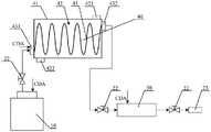
光阻胶是液晶显示面板生产中必不可少的原料。在彩膜基板的制备中,需要采用涂布机向基板上涂布光阻胶以制备彩膜。图1所示为一种光阻胶供给系统示意图。光阻胶容器10中的光阻胶在压缩干燥空气(Compressed Dry Air,CDA)的作用下通过三通阀门21后进入脱气过滤装置30。在脱气过滤装置30中,光阻胶被脱气处理并过滤,然后在压缩干燥空气的作用下,光阻胶从脱气过滤装置30排出并通过两通阀门22后进入涂布机喷嘴23进行涂布。目前,为了储存和运输的方便,光阻胶通常以20L光阻胶容器的形式从原料供应商处运输至面板生产商处。运输和储存均需要一定的时间,为了保证光阻胶的稳定性,运输和储存温度一般保持在5℃左右。然而,在对光阻胶进行涂布时,要求光阻胶的温度为23℃左右,因此,在涂布光阻胶前,需要对光阻胶进行升温处理,使其温度上升到所需要的温度。Photoresist is an essential raw material in the production of liquid crystal display panels. In the preparation of the color filter substrate, a coating machine needs to be used to coat the photoresist on the substrate to prepare the color filter. FIG. 1 is a schematic diagram of a photoresist adhesive supply system. The photoresist adhesive in the photoresist
现有光阻胶供给系统中,光阻胶升温处理主要有两种方式,一种是将20L光阻胶容器的光阻胶在常温下静置,静置时间一般为24小时;另一种是将20L光阻胶容器的光阻胶放置在常温水中,放置时间一般为18小时。这两种方式下,光阻胶与热源的接触面积保持不变,即均为20L光阻胶容器的外表面积,热交换面积小,所需升温时间较长。另外,现有的光阻胶升温处理方式,没有实时监控桶内光阻胶的温度,只是根据经验判断光阻胶是否达到要求温度,而光阻胶的实际温度是否满足要求并不能得到保证。再者,现有的光阻胶升温方式,对20L光阻胶容器的光阻胶进行升温处理,在满足生产需求量的同时,可能造成光阻胶剩余浪费,导致面板成本上升。In the existing photoresist adhesive supply system, there are two main ways to heat up the photoresist adhesive. One is to leave the photoresist adhesive in a 20L photoresist adhesive container at room temperature, and the rest time is generally 24 hours; The photoresist glue of the 20L photoresist glue container is placed in normal temperature water, and the placement time is generally 18 hours. In these two methods, the contact area between the photoresist adhesive and the heat source remains unchanged, that is, the outer surface area of the 20L photoresist adhesive container, the heat exchange area is small, and the required heating time is longer. In addition, the existing photoresist adhesive heating treatment method does not monitor the temperature of the photoresist adhesive in the barrel in real time, but only judges whether the photoresist adhesive reaches the required temperature based on experience, and whether the actual temperature of the photoresist adhesive meets the requirements cannot be guaranteed. Furthermore, in the existing photoresist adhesive heating method, the photoresist adhesive in a 20L photoresist adhesive container is heated up, which may cause residual waste of photoresist adhesive while meeting the production demand, resulting in an increase in panel cost.
综上,现有技术中的光阻胶升温处理方式,由于升温处理时间较长,无法及时满足生产需求,因此,如何降低光阻胶升温处理的时间成为亟待解决的技术问题。To sum up, the heating treatment method of the photoresist adhesive in the prior art cannot meet the production demand in time due to the long heating processing time. Therefore, how to reduce the heating processing time of the photoresist adhesive has become an urgent technical problem to be solved.
发明内容SUMMARY OF THE INVENTION
本发明实施例所要解决的技术问题是,提供一种光阻胶供给系统及涂布机,以解决光阻胶升温处理时间较长的技术问题。The technical problem to be solved by the embodiments of the present invention is to provide a photoresist adhesive supply system and a coating machine, so as to solve the technical problem that the photoresist adhesive takes a long time to heat up.
为了解决上述技术问题,本发明实施例提供了一种光阻胶供给系统,所述光阻胶供给系统包括设置在光阻胶容器与涂布机喷嘴之间的管路上的热交换装置。In order to solve the above technical problems, embodiments of the present invention provide a photoresist adhesive supply system, the photoresist adhesive supply system includes a heat exchange device disposed on a pipeline between a photoresist adhesive container and a coating machine nozzle.
可选地,所述热交换装置包括热源介质以及从所述热源介质中通过的热交换管路,所述热交换管路在所述热源介质中呈螺旋状或波浪状。Optionally, the heat exchange device includes a heat source medium and a heat exchange pipeline passing through the heat source medium, and the heat exchange pipeline is in a spiral or wave shape in the heat source medium.
可选地,光阻胶通过所述热源介质的方向与所述热源介质的流动方向相反。Optionally, the direction of the photoresist paste passing through the heat source medium is opposite to the flow direction of the heat source medium.
可选地,所述光阻胶供给系统还包括连接在所述热交换装置与涂布机喷嘴之间的第一缓冲容器。Optionally, the photoresist glue supply system further includes a first buffer container connected between the heat exchange device and the nozzle of the coater.
可选地,所述光阻胶供给系统还包括连接在所述热交换装置与涂布机喷嘴之间的温度检测装置。Optionally, the photoresist glue supply system further includes a temperature detection device connected between the heat exchange device and the nozzle of the coating machine.
可选地,所述光阻胶供给系统还包括第一三通阀门,所述第一三通阀门的第一端口与所述温度检测装置的输出端连通,所述第一三通阀门的第二端口与涂布机喷嘴连通,所述第一三通阀门的第三端口与所述热交换管路的入口端连通,当温度检测装置检测出光阻胶的温度等于或大于温度阈值时,所述第一三通阀门的第一端口与第二端口连通,当温度检测装置检测出光阻胶的温度小于温度阈值时,所述第一三通阀门的第一端口与第三端口连通。Optionally, the photoresist glue supply system further includes a first three-way valve, the first port of the first three-way valve is in communication with the output end of the temperature detection device, and the third The second port is communicated with the nozzle of the coating machine, and the third port of the first three-way valve is communicated with the inlet end of the heat exchange pipeline. When the temperature detection device detects that the temperature of the photoresist adhesive is equal to or greater than the temperature threshold, the The first port of the first three-way valve communicates with the second port, and when the temperature detection device detects that the temperature of the photoresist glue is lower than the temperature threshold, the first port of the first three-way valve communicates with the third port.
可选地,所述光阻胶供给系统还包括第二三通阀门,所述第二三通阀门的第一端口与所述热交换管路的入口端连通,所述第二三通阀门的第三端口与所述第一三通阀门的第三端口连通,所述第二三通阀门的第二端口接收待升温处理的光阻胶。Optionally, the photoresist glue supply system further includes a second three-way valve, the first port of the second three-way valve is in communication with the inlet end of the heat exchange pipeline, and the second three-way valve is The third port is communicated with the third port of the first three-way valve, and the second port of the second three-way valve receives the photoresist glue to be heated up.
可选地,所述光阻胶供给系统还包括连接在所述第一三通阀门的第三端口与所述第二三通阀门的第三端口之间的第二缓冲容器。Optionally, the photoresist glue supply system further includes a second buffer container connected between the third port of the first three-way valve and the third port of the second three-way valve.
可选地,所述第二缓冲容器设置有液位检测装置。Optionally, the second buffer container is provided with a liquid level detection device.
为了解决上述技术问题,本发明实施例提供了一种涂布机,包括以上所述的光阻胶供给系统。In order to solve the above technical problems, an embodiment of the present invention provides a coating machine, including the above-mentioned photoresist adhesive supply system.
本发明实施例的光阻胶供给系统,通过在光阻胶容器与涂布机喷嘴之间的管路上设置热交换装置,从而,当管路中的光阻胶流经热交换装置时,光阻胶与热交换装置中的热量产生热交换,使得光阻胶的温度上升。这样的光阻胶供给系统,参与热交换的光阻胶不再局限于位于光阻胶容器外表面处的光阻胶,而是光阻胶容器中的光阻胶均流通经过热交换装置进行热交换,扩大了光阻胶与热源的热交换面积,保证了光阻胶的升温效果,提升了光阻胶的升温处理效率,缩短了光阻胶的升温处理时间,提高了生产率。In the photoresist adhesive supply system of the embodiment of the present invention, a heat exchange device is arranged on the pipeline between the photoresist adhesive container and the nozzle of the coating machine, so that when the photoresist adhesive in the pipeline flows through the heat exchange device, the light The resist adhesive exchanges heat with the heat in the heat exchange device, so that the temperature of the photoresist adhesive increases. In such a photoresist adhesive supply system, the photoresist adhesive participating in heat exchange is no longer limited to the photoresist adhesive located on the outer surface of the photoresist adhesive container, but the photoresist adhesive in the photoresist adhesive container flows through the heat exchange device. The heat exchange expands the heat exchange area between the photoresist adhesive and the heat source, ensures the heating effect of the photoresist adhesive, improves the heating processing efficiency of the photoresist adhesive, shortens the heating processing time of the photoresist adhesive, and improves the productivity.
本发明的其它特征和优点将在随后的说明书中阐述,并且,部分地从说明书中变得显而易见,或者通过实施本发明而了解。本发明的目的和其他优点可通过在说明书、权利要求书以及附图中所特别指出的结构来实现和获得。Other features and advantages of the present invention will be set forth in the description which follows, and in part will be apparent from the description, or may be learned by practice of the invention. The objectives and other advantages of the invention may be realized and attained by the structure particularly pointed out in the description, claims and drawings.
附图说明Description of drawings
附图用来提供对本发明技术方案的进一步理解,并且构成说明书的一部分,与本申请的实施例一起用于解释本发明的技术方案,并不构成对本发明技术方案的限制。The accompanying drawings are used to provide a further understanding of the technical solutions of the present invention, and constitute a part of the specification. They are used to explain the technical solutions of the present invention together with the embodiments of the present application, and do not limit the technical solutions of the present invention.
图1所示为一种光阻胶供给系统示意图;Figure 1 shows a schematic diagram of a photoresist adhesive supply system;
图2为本发明第一实施例光阻胶供给系统的结构示意图;2 is a schematic structural diagram of a photoresist adhesive supply system according to a first embodiment of the present invention;
图3为本发明第二实施例光阻胶供给系统的结构示意图;3 is a schematic structural diagram of a photoresist adhesive supply system according to a second embodiment of the present invention;
图4为本发明第三实施例光阻胶供给系统的结构示意图;4 is a schematic structural diagram of a photoresist adhesive supply system according to a third embodiment of the present invention;
图5为本发明第四实施例光阻胶供给系统的结构示意图。FIG. 5 is a schematic structural diagram of a photoresist adhesive supply system according to a fourth embodiment of the present invention.
附图标记说明:Description of reference numbers:
10-光阻胶容器; 21-第二三通阀门; 22-两通阀门;10-resist glue container; 21-second three-way valve; 22-two-way valve;
23-涂布机喷嘴; 24-第一三通阀门; 25-温度检测装置;23-coating machine nozzle; 24-first three-way valve; 25-temperature detection device;
30-脱气过滤装置; 40-热交换装置; 41-壳体;30-Degassing filter device; 40-Heat exchange device; 41-Shell;
42-热源介质; 43-热交换管路; 51-第一缓冲容器;42-heat source medium; 43-heat exchange pipeline; 51-first buffer container;
52-第二缓冲容器; 421-热源介质输入口; 422-热源介质输出口;52-second buffer container; 421-heat source medium input port; 422-heat source medium output port;
431-热交换管路的入 432-热交换管路的出431-Inlet of heat exchange pipeline 432-Outlet of heat exchange pipeline
口端; 口端。port; port.
具体实施方式Detailed ways
为使本发明的目的、技术方案和优点更加清楚明白,下文中将结合附图对本发明的实施例进行详细说明。需要说明的是,在不冲突的情况下,本申请中的实施例及实施例中的特征可以相互任意组合。In order to make the objectives, technical solutions and advantages of the present invention clearer, the embodiments of the present invention will be described in detail below with reference to the accompanying drawings. It should be noted that, the embodiments in the present application and the features in the embodiments may be arbitrarily combined with each other if there is no conflict.
下面将通过具体的实施例详细介绍本发明的技术内容。The technical content of the present invention will be described in detail below through specific embodiments.
第一实施例:First embodiment:
图2为本发明第一实施例光阻胶供给系统的结构示意图。从图2中可以看出,该光阻胶供给系统包括设置在光阻胶容器10与涂布机喷嘴23之间的管路上的热交换装置40。FIG. 2 is a schematic structural diagram of a photoresist adhesive supply system according to a first embodiment of the present invention. As can be seen from FIG. 2 , the photoresist glue supply system includes a
本实施例的光阻胶供给系统,通过在光阻胶容器10与涂布机喷嘴23之间的管路上设置热交换装置40,从而,当管路中的光阻胶流经热交换装置40时,光阻胶与热交换装置40中的热量产生热交换,使得光阻胶的温度上升。这样的光阻胶供给系统,参与热交换的光阻胶不再局限于位于光阻胶容器外表面处的光阻胶,而是光阻胶容器中的光阻胶均流通经过热交换装置进行热交换,扩大了光阻胶与热源的热交换面积,保证了光阻胶的升温效果,提升了光阻胶的升温处理效率,缩短了光阻胶的升温处理时间,提高了生产率。In the photoresist adhesive supply system of this embodiment, a
进一步,热交换装置40包括壳体41、设置在壳体41内的热源介质42以及从热源介质42中通过的热交换管路43。涂布机进行光阻胶涂布时,光阻胶的温度一般为23℃左右,因此,通常,热源介质42的温度为20℃~25℃。热交换管路43的入口端431与20L的光阻胶容器10连通以接收待升温处理的光阻胶,热交换管路的出口端432输出升温后的光阻胶,通常与涂布机喷嘴23连通以向涂布机供给光阻胶。Further, the
本实施例的光阻胶供给系统的升温处理原理为,光阻胶容器10中的温度较低的光阻胶从热交换管路43的入口端431进入热交换管路43,在热交换管路43中,光阻胶与热源介质42发生热交换,光阻胶的温度升高,温度较高的光阻胶从热交换管路的出口端432输出后供给给涂布机喷嘴以进行涂布。热源介质42的温度为20℃~25℃,因此,当光阻胶通过热交换管路43后,从热交换管路43输出的光阻胶温度可以达到涂布机所需要的温度。The heating processing principle of the photoresist adhesive supply system in this embodiment is that the photoresist adhesive with a lower temperature in the photoresist
本发明实施例的光阻胶供给系统,采用热交换装置40对光阻胶进行升温处理,20L光阻胶容器中的光阻胶均流通经过热交换装置40中的热交换管路43与热源介质42进行热交换,直接进行热交换的光阻胶不再局限于位于20L的光阻胶容器的外表面处的光阻胶,从而,扩大了光阻胶与热源的热交换面积,保证了光阻胶的升温效果,提升了光阻胶的升温处理效率,缩短了光阻胶的升温处理时间,提高了生产率。In the photoresist adhesive supply system of the embodiment of the present invention, the
为了进一步增加光阻胶的热交换面积,热交换管路43在热源介质42中呈螺旋状或波浪状,从而延长了光阻胶通过热源介质42的时间,进一步增大了热交换管路43的热交换面积,进一步提升了升温处理的效率。In order to further increase the heat exchange area of the photoresist adhesive, the
为了达到热交换的目的,热源介质可以为呈一定规律排布的电阻丝,电阻丝通电发热。当给电阻丝通电后,电阻丝发热,使得电阻丝周围的气体发热,从而使得从电阻丝中间通过的热交换管路温度上升,进而使得热交换管路中的光阻胶获得热量温度上升。当然,热源介质并不限于电阻丝,还可以为其它可以产生热量的物质。In order to achieve the purpose of heat exchange, the heat source medium can be resistance wires arranged in a certain pattern, and the resistance wires are energized to generate heat. When the resistance wire is energized, the resistance wire heats up, causing the gas around the resistance wire to heat up, so that the temperature of the heat exchange pipeline passing through the middle of the resistance wire rises, and the photoresist glue in the heat exchange pipeline obtains heat and the temperature rises. Of course, the heat source medium is not limited to resistance wires, but can also be other substances that can generate heat.
在本实施例中,为了获得高效、温和的加热效果,本实施例中的热源介质优选为流体介质。当热源介质为流体介质时,光阻胶通过热源介质的方向与热源介质的流动方向相反,从而,热源介质可以与光阻胶进行充分的热交换,进一步提高热交换的效率。例如,在图2中,光阻胶从壳体的左下端朝向右上端通过热源介质,热源介质的流动方向为从壳体的右上端朝向左下端,光阻胶通过热源介质42的方向与热源介质42的流动方向相反。在本实施例中,热源介质42为水,容易理解的是,热源介质也可以为其它物质,如蒸汽、油等,均可以达到同样的技术效果。In this embodiment, in order to obtain an efficient and gentle heating effect, the heat source medium in this embodiment is preferably a fluid medium. When the heat source medium is a fluid medium, the direction of the photoresist adhesive passing through the heat source medium is opposite to the flow direction of the heat source medium, so that the heat source medium can conduct sufficient heat exchange with the photoresist adhesive, further improving the heat exchange efficiency. For example, in FIG. 2 , the photoresist glue passes through the heat source medium from the lower left end to the upper right end of the casing, the flow direction of the heat source medium is from the upper right end of the casing to the lower left end, and the direction of the photoresist glue passing through the heat source medium 42 is related to the heat source The flow direction of the medium 42 is opposite. In this embodiment, the heat source medium 42 is water. It is easy to understand that the heat source medium can also be other substances, such as steam, oil, etc., which can achieve the same technical effect.
为了保证热交换管路43的热交换效果和使用寿命,热交换管路43的材质要具有较高的导热率,而且要耐高压。例如,热交换管路43的材质可以为不锈钢等。In order to ensure the heat exchange effect and service life of the
容易理解的是,光阻胶与热源介质进行热交换后,热源介质的温度会下降,为了始终保持热源介质的温度,在本实施例中,热交换装置40还包括热源介质输入口421和热源介质输出口422,以用于更换热源介质,使壳体41内的热源介质的温度始终保持在20℃~25℃,保证升温处理效果。为了实现热源介质的自动更换,热源介质42中设置有温度检测仪器,当热源介质42的温度降低时,温度检测仪器可以发出控制信号,从而实现热源介质的智能化更换。It is easy to understand that the temperature of the heat source medium will drop after the photoresist adhesive exchanges heat with the heat source medium. In order to always maintain the temperature of the heat source medium, in this embodiment, the
从图2中还可以看出,本实施例的光阻胶供给系统还包括脱气过滤装置30。热交换管路43的出口端432与脱气处理装置30的入口端连通,脱气过滤装置30的出口端与涂布机喷嘴23连通。这样,满足温度要求的光阻胶在进入喷嘴23前,经过脱气过滤装置30进行脱气和过滤处理,保证了光阻胶的品质,提高了产品良率。容易理解的是,脱气过滤装置30可以设置在光阻胶容器10与涂布机喷嘴23之间管路的任意位置,并不限于图2中所示的位置。在具体实施中,为了方便部件的更换,通常在20L的光阻胶容器10的出口端设置两通阀门22,同时,在脱气过滤装置30的入口端和出口端也均设置两通阀门22。为了保证涂布机喷嘴23处的涂布压力,还可以在涂布机喷嘴23的入口端设置压送泵,从而保证涂布机喷嘴23的涂布压力。在对光阻胶进行升温处理时,为了促使光阻胶通过热交换管路43,在热交换管路的入口端431处向热交换管路中通入CDA,以促进光阻胶的流动,提高升温处理效率。It can also be seen from FIG. 2 that the photoresist adhesive supply system of this embodiment further includes a
第二实施例:Second embodiment:
图3为本发明第二实施例光阻胶供给系统的结构示意图。本实施例的光阻胶供给系统在第一实施例的基础上,还包括连接在热交换管路的出口端432与涂布机喷嘴23之间的温度检测装置25。具体地,如图3所示,温度检测装置25可以安装在热交换管路的出口端432与脱气处理装置30之间,容易理解的是,温度检测装置25也可以安装在脱气处理装置30与涂布机喷嘴23之间。温度检测装置25可以实时检测从热交换装置40输出的光阻胶的温度,以实时判定热交换装置40的升温处理效果,同时,当从热交换装置40输出的光阻胶不满足温度要求时,可以提醒用户是否停止光阻胶的使用,进行设备检修或对光阻胶进行再处理。FIG. 3 is a schematic structural diagram of a photoresist adhesive supply system according to a second embodiment of the present invention. On the basis of the first embodiment, the photoresist adhesive supply system of this embodiment further includes a
第三实施例:Third embodiment:
图4为本发明第三实施例光阻胶供给系统的结构示意图。本实施例的光阻胶供给系统在第二实施例的基础上,还包括第一三通阀门24。如图4所示,第一三通阀门24的第一端口与温度检测装置25的输出端连通,第一三通阀门24的第二端口与涂布机喷嘴23连通,第一三通阀门24的第三端口与热交换管路43的入口端431连通,当温度检测装置25检测出光阻胶的温度等于或大于温度阈值时,第一三通阀门24的第一端口与第二端口连通,当温度检测装置25检测出光阻胶的温度小于温度阈值时,第一三通阀门24的第一端口与第三端口连通。这样的光阻胶供给系统,实现了对光阻胶升温处理的智能控制,温度检测装置25不仅实时检测热交换装置40输出的光阻胶的温度,而且,当光阻胶的温度没有达到要求的温度阈值时,通过第一三通阀门24的第一端口与第三端口连通,可以使低于温度阈值的光阻胶重新进入热交换管路43中进行升温处理,以获得满足温度阈值的光阻胶。温度阈值为光阻胶涂布时所需的温度,通常,温度阈值为23℃左右。FIG. 4 is a schematic structural diagram of a photoresist adhesive supply system according to a third embodiment of the present invention. On the basis of the second embodiment, the photoresist adhesive supply system of this embodiment further includes a first three-
在具体实施中,为了避免由第一三通阀门24的第三端口返回的光阻胶与未经过升温处理的光阻胶发生热交换,优选地,热交换管路43的入口端设置有第二三通阀门21,第二三通阀门21的第一端口与热交换管路43的入口端连通,第二三通阀门21的第三端口与第一三通阀门21的第三端口连通,第二三通阀门21的第二端口接收待升温处理的光阻胶,通常,第二三通阀门21的第二端口与光阻胶容器10连通。当温度检测装置25检测出光阻胶的温度等于或大于温度阈值时,第二三通阀门21的第一端口与第二端口连通,当温度检测装置25检测出光阻胶的温度小于温度阈值时,第二三通阀门21的第一端口与第三端口连通。这样,由第一三通阀门24的第三端口返回的光阻胶就可以直接进入热交换管路43中进行再次升温处理,避免了由第一三通阀门24的第三端口返回的已经升温处理过的光阻胶与光阻胶容器10中的光阻胶产生热交换,避免了能量损失,进一步提高了热交换装置40的升温处理效率。In a specific implementation, in order to avoid heat exchange between the photoresist adhesive returned by the third port of the first three-
为了进一步实现升温处理的自动智能控制,第一三通阀门24和第二三通阀门21可以优选为电磁三通阀。In order to further realize the automatic and intelligent control of the heating process, the first three-
在本实施例中,第一三通阀门24设置在温度检测装置25与脱气过滤装置30之间。In this embodiment, the first three-
本发明实施例光阻胶供给系统的工作原理如下:The working principle of the photoresist adhesive supply system according to the embodiment of the present invention is as follows:
初始状态,第一三通阀门24的第一端口和第二端口连通,第二三通阀门21的第一端口和第二端口连通,光阻胶容器10中的温度较低的光阻胶在压缩干燥空气的压力下,通过两通阀门22、第二三通阀门21的第二端口和第一端口、热交换管路43的入口端431进入到热交换管路43中。在热交换管路43中,光阻胶与热源介质42进行热交换,光阻胶的温度升高,并从热交换管路43的出口端432排出。温度检测装置25对升温处理后的光阻胶的温度进行实时检测,当温度检测装置25检测到光阻胶的温度大于或等于温度阈值时,第一三通阀门24的第一端口和第二端口仍保持连通,同时第二三通阀门21的第二人端口和第一端口仍保持连通,流经温度检测装置25的光阻胶通过第一三通阀门24的第一端口和第二端口进入到脱气过滤装置30中进行脱气过滤处理,然后进入涂布机喷嘴23进行涂布;当温度检测装置25检测到光阻胶的温度小于温度阈值时,第一三通阀门24的第一端口和第二端口关端而第一端口和第三端口连通,同时,第二三通阀门21的第一端口和第二端口关端而第一端口和第三端口连通,流经温度检测装置25的光阻胶通过第一三通阀门24的第一端口和第三端口、第二三通阀门21的第三端口和第一端口以及热交换管路43的入口端431进入到热交换管路43中进行再次热交换,最终得到等于或大于温度阈值的光阻胶。In the initial state, the first port and the second port of the first three-
第四实施例:Fourth embodiment:
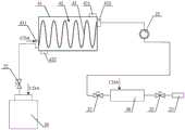
图5为本发明第四实施例光阻胶供给系统的结构示意图。本实施例的光阻胶供给系统在第三实施例的基础上,还包括连接在热交换装置40与涂布机喷嘴23之间的第一缓冲容器51,即连接在热交换管路的出口端432与涂布机喷嘴23之间的第一缓冲容器51。在本实施例中,第一缓冲容器51设置在第一三通阀门24的第二端口与涂布机喷嘴23之间。通常,第一缓冲容器51的入口端设置在上部,出口端设置在底部,这样,光阻胶就可以在重力的作用下从第一缓冲容器51中流出,促进光阻胶朝向涂布机喷嘴23流动。FIG. 5 is a schematic structural diagram of a photoresist adhesive supply system according to a fourth embodiment of the present invention. On the basis of the third embodiment, the photoresist adhesive supply system of this embodiment further includes a
在进行光阻胶涂布时,光阻胶的使用量往往比较大,在涂布机喷嘴23之前设置第一缓冲容器51后,第一缓冲容器51可以储存适量的光阻胶,稳定了光阻胶的供应速度,避免了涂布过程中出现光阻胶不足。同时,为了促使光阻胶顺畅进入涂布机喷嘴,第一缓冲容器51的上方设置有CDA,以提供所需的光阻胶供应压力,保证光阻胶的供应速度。在本实施例中,第一缓冲容器51设置在脱气处理装置30之前,如图5所示。当停止光阻胶涂布时,可以关断脱气处理装置30入口端的两通阀门,将光阻胶储存在第一缓冲容器51中,以待下次使用,避免了光阻胶的浪费。When the photoresist is coated, the amount of photoresist used is often relatively large. After the
为了防止第二三通阀门21的频繁切换,可以在第一三通阀门24的第三端口与第二三通阀门21的第三端口之间连接第二缓冲容器52,以储存需要进行再次升温处理的光阻胶。当第二缓冲容器52中的光阻胶达到一定量时,才使得第二三通阀门21的第一端口与第三端口连通,从而避免了第一三通阀门21的频繁切换,提高光阻胶升温处理的效率。同样,为了促使光阻胶顺畅回流至热交换管路43,第二缓冲容器52的上方也设置有CDA。为了实现第二三通阀门21的自动控制,本实施例中,第二缓冲容器52设置有液位检测装置53,液位检测装置53用于检测第二缓冲容器52中的光阻胶液位,具体为,液位检测装置53可以检测第二缓冲容器52中的光阻胶的高液位和低液位。当第二缓冲容器52中储存的光阻胶的量达到高液位时,液位检测装置53发出对应的第一信号,第二三通阀门21的第一端口与第二端口关端而第一端口与第三端口连通,第二缓冲容器52中的光阻胶再次进入热交换管路43中进行升温处理,当液位检测装置53发出与低液位对应的第二信号时,第二三通阀门21的第一端口和第三端口关端而第一端口与第二端口连通,第二缓冲容器52进行光阻胶储存,光阻胶容器10中的光阻胶进入热交换管路43中进行升温处理。In order to prevent frequent switching of the second three-
本发明实施例光阻胶供给系统的工作原理如下:The working principle of the photoresist adhesive supply system according to the embodiment of the present invention is as follows:
初始状态,第一三通阀门24的第一端口和第二端口连通,第二三通阀门21的第一端口和第二端口连通,光阻胶容器10中的温度较低的光阻胶在压缩干燥空气的压力下,通过两通阀门22、第二三通阀门21的第二端口和第一端口、热交换管路43的入口端431进入到热交换管路43中。在热交换管路43中,光阻胶与热源介质42进行热交换,光阻胶的温度升高,并从热交换管路43的出口端432排出。温度检测装置25对升温处理后的光阻胶的温度进行实时检测,当温度检测装置25检测到光阻胶的温度大于或等于温度阈值时,第一三通阀门24的第一端口和第二端口仍保持连通,同时第二三通阀门21的第二人端口和第一端口仍保持连通,流经温度检测装置25的光阻胶通过第一三通阀门24的第一端口和第二端口进入到第一缓冲容器51中供给给涂布机喷嘴;当温度检测装置25检测到光阻胶的温度小于温度阈值时,第一三通阀门24的第一端口和第二端口关端而第一端口和第三端口连通,流经温度检测装置25的光阻胶通过第一三通阀门24的第一端口和第三端口进入到第二缓冲容器52中并储存。当液位检测装置53发出第一信号时,第二三通阀门21的第一端口和第二端口关端而第一端口和第三端口连通,第二缓冲容器52中储存的光阻胶通过第二三通阀门21的第三端口和第一端口以及热交换管路43的入口端431进入到热交换管路43中进行再次热交换,以便最终得到等于或大于温度阈值的光阻胶;当液位检测装置53发出第二信号时,第二三通阀门21的第一端口和第三端口关端而第一端口与第二端口连通,第二缓冲容器52进行光阻胶储存,光阻胶容器10中的光阻胶进入热交换管路43中进行升温处理。这样,就进一步实现了光阻胶升温处理的智能控制。In the initial state, the first port and the second port of the first three-
容易理解的是,第一缓冲容器的设置并不限于在第三实施例的基础上,也可以在第一实施例的基础上,在热交换装置与涂布机喷嘴之间设置第一缓冲容器,同样可以起到稳定光阻胶的供应速度的效果,也就是说,只要在涂布机喷嘴之前设置第一缓冲容器,均可以达到相同的技术效果。It is easy to understand that the arrangement of the first buffer container is not limited to the third embodiment, and the first buffer container can also be arranged between the heat exchange device and the nozzle of the coating machine on the basis of the first embodiment. , can also have the effect of stabilizing the supply speed of the photoresist adhesive, that is to say, as long as the first buffer container is set before the nozzle of the coating machine, the same technical effect can be achieved.
第五实施例:Fifth embodiment:
基于上述实施例的发明构思,本发明实施例提出了一种涂布机,该涂布机包括以上所述的光阻胶供给系统。Based on the inventive concept of the above embodiments, the embodiments of the present invention provide a coating machine, which includes the above-mentioned photoresist adhesive supply system.
在本发明实施例的描述中,需要理解的是,术语“中部”、“上”、“下”、“前”、“后”、“竖直”、“水平”、“顶”、“底”、“内”、“外”等指示的方位或位置关系为基于附图所示的方位或位置关系,仅是为了便于描述本发明和简化描述,而不是指示或暗示所指的装置或元件必须具有特定的方位、以特定的方位构造和操作,因此不能理解为对本发明的限制。In the description of the embodiments of the present invention, it should be understood that the terms "middle", "upper", "lower", "front", "rear", "vertical", "horizontal", "top", "bottom" ", "inside", "outside", etc. indicate the orientation or positional relationship based on the orientation or positional relationship shown in the accompanying drawings, which are only for the convenience of describing the present invention and simplifying the description, rather than indicating or implying the indicated device or element. It must have a specific orientation, be constructed and operate in a specific orientation, and therefore should not be construed as a limitation of the present invention.
在本发明实施例的描述中,需要说明的是,除非另有明确的规定和限定,术语“安装”、“相连”、“连接”应做广义理解,例如,可以是固定连接,也可以是可拆卸连接,或一体地连接;可以是机械连接,也可以是电连接;可以是直接相连,也可以通过中间媒介间接相连,可以是两个元件内部的连通。对于本领域的普通技术人员而言,可以具体情况理解上述术语在本发明中的具体含义。In the description of the embodiments of the present invention, it should be noted that the terms "installed", "connected" and "connected" should be understood in a broad sense, unless otherwise expressly specified and limited. For example, it may be a fixed connection or a Removable connection, or integral connection; can be mechanical connection, can also be electrical connection; can be directly connected, can also be indirectly connected through an intermediate medium, can be internal communication between two components. For those of ordinary skill in the art, the specific meanings of the above terms in the present invention can be understood in specific situations.
虽然本发明所揭露的实施方式如上,但所述的内容仅为便于理解本发明而采用的实施方式,并非用以限定本发明。任何本发明所属领域内的技术人员,在不脱离本发明所揭露的精神和范围的前提下,可以在实施的形式及细节上进行任何的修改与变化,但本发明的专利保护范围,仍须以所附的权利要求书所界定的范围为准。Although the embodiments disclosed in the present invention are as above, the described contents are only the embodiments adopted to facilitate the understanding of the present invention, and are not intended to limit the present invention. Any person skilled in the art to which the present invention belongs, without departing from the spirit and scope disclosed by the present invention, can make any modifications and changes in the form and details of the implementation, but the scope of the patent protection of the present invention still needs to be The scope defined by the appended claims shall prevail.
Claims (5)
Translated fromChinesePriority Applications (1)
| Application Number | Priority Date | Filing Date | Title |
|---|---|---|---|
| CN201810099599.7ACN108187979B (en) | 2018-01-31 | 2018-01-31 | Photoresist glue supply system and coating machine |
Applications Claiming Priority (1)
| Application Number | Priority Date | Filing Date | Title |
|---|---|---|---|
| CN201810099599.7ACN108187979B (en) | 2018-01-31 | 2018-01-31 | Photoresist glue supply system and coating machine |
Publications (2)
| Publication Number | Publication Date |
|---|---|
| CN108187979A CN108187979A (en) | 2018-06-22 |
| CN108187979Btrue CN108187979B (en) | 2020-06-23 |
Family
ID=62592223
Family Applications (1)
| Application Number | Title | Priority Date | Filing Date |
|---|---|---|---|
| CN201810099599.7AActiveCN108187979B (en) | 2018-01-31 | 2018-01-31 | Photoresist glue supply system and coating machine |
Country Status (1)
| Country | Link |
|---|---|
| CN (1) | CN108187979B (en) |
Family Cites Families (6)
| Publication number | Priority date | Publication date | Assignee | Title |
|---|---|---|---|---|
| EP1433036A4 (en)* | 2001-10-01 | 2008-10-22 | Entegris Inc | Apparatus for conditioning the temperature of a fluid |
| CN2861006Y (en)* | 2005-12-15 | 2007-01-24 | 威海广泰空港设备股份有限公司 | Liquid-way system for de-icing vehicle |
| NL2005167A (en)* | 2009-10-02 | 2011-04-05 | Asml Netherlands Bv | Lithographic apparatus and a method of operating the apparatus. |
| CN102338993A (en)* | 2010-07-27 | 2012-02-01 | 中国科学院微电子研究所 | Sample wafer photoresist removing device and method |
| CN205988843U (en)* | 2016-07-26 | 2017-03-01 | 惠州市浩明科技股份有限公司 | A kind of photoresistance fluid reservoir and Photoresisting coating machines |
| CN107121897A (en)* | 2017-05-25 | 2017-09-01 | 上海华力微电子有限公司 | A kind of photoresist circuit design |
- 2018
- 2018-01-31CNCN201810099599.7Apatent/CN108187979B/enactiveActive
Also Published As
| Publication number | Publication date |
|---|---|
| CN108187979A (en) | 2018-06-22 |
Similar Documents
| Publication | Publication Date | Title |
|---|---|---|
| CN106880291B (en) | Regenerative temperature-adjustable water boiler and control method thereof | |
| CN103322682A (en) | Domestic water circulation system | |
| CN107902784A (en) | Instant heating type water purifier and its waterway control system | |
| CN104154782A (en) | Heat exchanger of heat pump water tank and heat exchange method | |
| CN108187979B (en) | Photoresist glue supply system and coating machine | |
| CN203856565U (en) | Engine cooling system based on phase change fluid/water | |
| CN110220307A (en) | Descaling assembly and gas water heater | |
| CN107892426A (en) | Water purification machine and its water circuit system | |
| CN106361152A (en) | Double temperature energy storage type intelligent drinking water device | |
| CN208075335U (en) | A descaling component and a gas water heater | |
| CN207703077U (en) | Heat exchanger on-line cleaning system | |
| CN102395256B (en) | Cooling device of heating element | |
| CN209223843U (en) | A polishing liquid filtration system | |
| CN204494769U (en) | A kind of four core stepping water boilers | |
| CN104676858B (en) | Quick heating mixed water storage tank | |
| CN108917178B (en) | Instant heating cup, heating system and electric water heater | |
| CN114576695A (en) | Air source heat pump pressure-bearing hot water system and operation method | |
| CN208519983U (en) | A kind of heating thermostatic control tank group | |
| CN208170590U (en) | A kind of energy-storage air conditioner system | |
| CN206440178U (en) | Heat exchanger purging system in a kind of L alanine production process | |
| CN206160462U (en) | Little kitchen is precious | |
| CN207182128U (en) | A temperature control device for glass frosting equipment | |
| CN205191702U (en) | Intelligence temperature heating device | |
| CN222688426U (en) | A liquid supply system | |
| CN213040739U (en) | Heating and bathing dual-purpose furnace and system comprising same |
Legal Events
| Date | Code | Title | Description |
|---|---|---|---|
| PB01 | Publication | ||
| PB01 | Publication | ||
| SE01 | Entry into force of request for substantive examination | ||
| SE01 | Entry into force of request for substantive examination | ||
| GR01 | Patent grant | ||
| GR01 | Patent grant |