CN108175613B - Limb support frame for burn patients - Google Patents
Limb support frame for burn patientsDownload PDFInfo
- Publication number
- CN108175613B CN108175613BCN201810041070.XACN201810041070ACN108175613BCN 108175613 BCN108175613 BCN 108175613BCN 201810041070 ACN201810041070 ACN 201810041070ACN 108175613 BCN108175613 BCN 108175613B
- Authority
- CN
- China
- Prior art keywords
- travel switch
- switch
- seat
- push rod
- electric push
- Prior art date
- Legal status (The legal status is an assumption and is not a legal conclusion. Google has not performed a legal analysis and makes no representation as to the accuracy of the status listed.)
- Expired - Fee Related
Links
Images


Classifications
- A—HUMAN NECESSITIES
- A61—MEDICAL OR VETERINARY SCIENCE; HYGIENE
- A61G—TRANSPORT, PERSONAL CONVEYANCES, OR ACCOMMODATION SPECIALLY ADAPTED FOR PATIENTS OR DISABLED PERSONS; OPERATING TABLES OR CHAIRS; CHAIRS FOR DENTISTRY; FUNERAL DEVICES
- A61G7/00—Beds specially adapted for nursing; Devices for lifting patients or disabled persons
- A61G7/05—Parts, details or accessories of beds
- A61G7/065—Rests specially adapted therefor
- A61G7/075—Rests specially adapted therefor for the limbs
- A—HUMAN NECESSITIES
- A61—MEDICAL OR VETERINARY SCIENCE; HYGIENE
- A61G—TRANSPORT, PERSONAL CONVEYANCES, OR ACCOMMODATION SPECIALLY ADAPTED FOR PATIENTS OR DISABLED PERSONS; OPERATING TABLES OR CHAIRS; CHAIRS FOR DENTISTRY; FUNERAL DEVICES
- A61G12/00—Accommodation for nursing, e.g. in hospitals, not covered by groups A61G1/00 - A61G11/00, e.g. trolleys for transport of medicaments or food; Prescription lists
- A—HUMAN NECESSITIES
- A61—MEDICAL OR VETERINARY SCIENCE; HYGIENE
- A61G—TRANSPORT, PERSONAL CONVEYANCES, OR ACCOMMODATION SPECIALLY ADAPTED FOR PATIENTS OR DISABLED PERSONS; OPERATING TABLES OR CHAIRS; CHAIRS FOR DENTISTRY; FUNERAL DEVICES
- A61G7/00—Beds specially adapted for nursing; Devices for lifting patients or disabled persons
- A61G7/05—Parts, details or accessories of beds
- A61G7/065—Rests specially adapted therefor
- A61G7/075—Rests specially adapted therefor for the limbs
- A61G7/0755—Rests specially adapted therefor for the limbs for the legs or feet
- A—HUMAN NECESSITIES
- A61—MEDICAL OR VETERINARY SCIENCE; HYGIENE
- A61G—TRANSPORT, PERSONAL CONVEYANCES, OR ACCOMMODATION SPECIALLY ADAPTED FOR PATIENTS OR DISABLED PERSONS; OPERATING TABLES OR CHAIRS; CHAIRS FOR DENTISTRY; FUNERAL DEVICES
- A61G2203/00—General characteristics of devices
- A61G2203/70—General characteristics of devices with special adaptations, e.g. for safety or comfort
- Y—GENERAL TAGGING OF NEW TECHNOLOGICAL DEVELOPMENTS; GENERAL TAGGING OF CROSS-SECTIONAL TECHNOLOGIES SPANNING OVER SEVERAL SECTIONS OF THE IPC; TECHNICAL SUBJECTS COVERED BY FORMER USPC CROSS-REFERENCE ART COLLECTIONS [XRACs] AND DIGESTS
- Y02—TECHNOLOGIES OR APPLICATIONS FOR MITIGATION OR ADAPTATION AGAINST CLIMATE CHANGE
- Y02A—TECHNOLOGIES FOR ADAPTATION TO CLIMATE CHANGE
- Y02A50/00—TECHNOLOGIES FOR ADAPTATION TO CLIMATE CHANGE in human health protection, e.g. against extreme weather
- Y02A50/30—Against vector-borne diseases, e.g. mosquito-borne, fly-borne, tick-borne or waterborne diseases whose impact is exacerbated by climate change
Landscapes
- Health & Medical Sciences (AREA)
- Nursing (AREA)
- Life Sciences & Earth Sciences (AREA)
- Animal Behavior & Ethology (AREA)
- General Health & Medical Sciences (AREA)
- Public Health (AREA)
- Veterinary Medicine (AREA)
- Rehabilitation Tools (AREA)
Abstract
Description
Translated fromChinese技术领域technical field
本发明涉及医疗器械技术领域,尤其涉及烧伤患者用肢体支撑架。The invention relates to the technical field of medical devices, in particular to a limb support frame for burn patients.
背景技术Background technique
目前,临床部分烧伤患者,在术后康复期间,因术后护理治疗,医护人员需要定时对患肢烧伤部位进行药物更换,而在医护人员对患者肢体进行药物更换时,因临床缺少烧伤患者专用的肢体支撑架,从而不仅给医护人员操作带来极大的不便,需要多位医护人员将患者肢体进行托举,再由其中一名医护人员对其进行药物更换,此外,也容易对患者烧伤创口产生二次伤害,给患者术后康复带来极大的影响,不利于临床的推广应用,与此同时,在换药的过程中,药液或创口血液也会向下滴落,即对环境造成污染,鉴于以上缺陷,实有必要设计烧伤患者用肢体支撑架。At present, during the postoperative rehabilitation period of some clinical burn patients, due to postoperative nursing treatment, medical staff need to regularly replace the drug on the burnt part of the affected limb. The limb support frame not only brings great inconvenience to the medical staff, but also requires multiple medical staff to lift the patient's limbs, and then one of the medical staff replaces the medicine. In addition, it is easy to burn the patient Wounds cause secondary injuries, which have a great impact on postoperative rehabilitation of patients, which is not conducive to clinical promotion and application. The environment causes pollution. In view of the above defects, it is necessary to design a limb support frame for burn patients.
发明内容Contents of the invention
本发明所要解决的技术问题在于:提供烧伤患者用肢体支撑架,来解决背景技术提出的问题。The technical problem to be solved by the present invention is to provide a limb support frame for burn patients to solve the problems raised by the background technology.
为解决上述技术问题,本发明的技术方案是:烧伤患者用肢体支撑架,包括底板、固定座、步进电机、转轴、齿轮、滑槽、齿条板、第一行程开关、第二行程开关、避让孔、连接座、电动推杆、滑轨、第三行程开关、第四行程开关、滑座、导向杆、滑动套、固定板、卡套、弹性布,所述的固定座位于底板顶部左侧,所述的固定座与底板螺纹相连,所述的步进电机位于固定座前端中部,所述的步进电机与固定座螺纹相连,所述的转轴位于步进电机后端,所述的转轴与步进电机紧配相连,且所述的转轴与固定座转动相连,所述的齿轮贯穿于转轴,所述的齿轮与转轴紧配相连,所述的滑槽位于固定座内部右侧,所述的滑槽为矩形凹槽,所述的齿条板位于滑槽内部,所述的齿条板与固定座滑动相连,且所述的齿条板与齿轮轮齿啮合相连,所述的第一行程开关位于滑槽顶端,所述的第一行程开关与固定座螺纹相连,且所述的第一行程开关与步进电机导线相连,所述的第二行程开关位于滑槽底端,所述的第二行程开关与固定座螺纹相连,且所述的第二行程开关与步进电机导线相连,所述的避让孔位于固定座内部右侧,所述的避让孔为矩形通孔,所述的连接座位于齿条板右侧上端,所述的连接座与齿条板螺纹相连,且所述的连接座与固定座滑动相连,所述的电动推杆位于齿条板右侧下端,所述的电动推杆与齿条板螺纹相连,且所述的电动推杆与固定座滑动相连,所述的滑轨位于底板顶部右侧,所述的滑轨与底板螺纹相连,所述的第三行程开关位于滑轨左侧,所述的第三行程开关与滑轨螺纹相连,且所述的第三行程开关与电动推杆导线相连,所述的第四行程开关位于滑轨右侧,所述的第四行程开关与滑轨螺纹相连,且所述的第四行程开关与电动推杆导线相连,所述的滑座位于滑轨外壁上端,所述的滑座与滑轨滑动相连,所述的导向杆位于滑座顶部,所述的导向杆与滑座一体相连,所述的滑动套位于导向杆外壁,所述的滑动套与导向杆滑动相连,且所述的滑动套与电动推杆螺纹相连,所述的固定板位于连接座和滑动套顶部,所述的固定板分别与连接座和滑动套螺纹相连,所述的卡套位于固定板外壁,所述的卡套与固定板活动相连,所述的弹性布位于卡套两两之间,所述的弹性布左右两端分别与卡套胶水相连。In order to solve the above-mentioned technical problems, the technical solution of the present invention is: a limb support frame for burn patients, including a base plate, a fixed seat, a stepping motor, a rotating shaft, a gear, a chute, a rack plate, a first stroke switch, and a second stroke switch , avoidance hole, connecting seat, electric push rod, slide rail, third travel switch, fourth travel switch, sliding seat, guide rod, sliding sleeve, fixing plate, card sleeve, elastic cloth, and the fixing seat is located on the top of the bottom plate On the left side, the fixed seat is threadedly connected with the bottom plate, the stepper motor is located in the middle of the front end of the fixed seat, the stepper motor is threadedly connected with the fixed seat, the rotating shaft is located at the rear end of the stepper motor, and the The rotating shaft is tightly connected to the stepping motor, and the rotating shaft is connected to the fixed seat in rotation, the gear runs through the rotating shaft, the gear is closely connected to the rotating shaft, and the chute is located on the right side inside the fixed seat , the chute is a rectangular groove, the rack plate is located inside the chute, the rack plate is slidably connected with the fixed seat, and the rack plate is meshed with the gear teeth, the The first travel switch is located at the top of the chute, the first travel switch is threadedly connected to the fixing seat, and the first travel switch is connected to the stepping motor wire, and the second travel switch is located at the bottom of the chute , the second travel switch is threadedly connected to the fixing seat, and the second travel switch is connected to the wire of the stepping motor, the avoidance hole is located on the right side inside the fixing seat, and the avoidance hole is a rectangular through hole , the connecting seat is located at the upper right side of the rack plate, the connecting seat is threadedly connected with the rack plate, and the connecting seat is slidingly connected with the fixed seat, and the electric push rod is located at the right side of the rack plate At the lower end, the electric push rod is threadedly connected with the rack plate, and the electric push rod is slidably connected with the fixing seat. The third travel switch is located on the left side of the slide rail, the third travel switch is connected to the slide rail thread, and the third travel switch is connected to the wire of the electric push rod, and the fourth travel switch is located on the slide rail On the right side, the fourth travel switch is threadedly connected to the slide rail, and the fourth travel switch is connected to the wire of the electric push rod. The slide seat is located at the upper end of the outer wall of the slide rail. The slide seat and the slide rail Slidingly connected, the guide rod is located at the top of the slide seat, the guide rod is integrally connected with the slide seat, the slide sleeve is located on the outer wall of the guide rod, the slide sleeve is slidably connected with the guide rod, and the slide The sleeve is threadedly connected with the electric push rod, the fixed plate is located at the top of the connecting seat and the sliding sleeve, the fixed plate is respectively threaded with the connecting seat and the sliding sleeve, the ferrule is located on the outer wall of the fixed plate, and the clamping The sleeve is movably connected with the fixing plate, the elastic cloth is located between two ferrules, and the left and right ends of the elastic cloth are respectively connected with the ferrule glue.
进一步,所述的固定座前端左侧还设有第一开关,所述的第一开关与固定座螺纹相连,且所述的第一开关与步进电机和第一行程开关导线相连。Further, a first switch is provided on the left side of the front end of the fixing seat, the first switch is threadedly connected with the fixing seat, and the first switch is connected with the stepper motor and the wire of the first travel switch.
进一步,所述的固定座前端左侧还设有第二开关,所述的第二开关与固定座螺纹相连,且所述的第二开关与步进电机和第二行程开关导线相连。Further, a second switch is provided on the left side of the front end of the fixing seat, the second switch is threadedly connected with the fixing seat, and the second switch is connected with the stepping motor and the second travel switch wire.
进一步,所述的固定座前端右侧还设有第三开关,所述的第三开关与固定座螺纹相连,且所述的第三开关与电动推杆和第三行程开关导线相连。Further, a third switch is provided on the right side of the front end of the fixing seat, the third switch is threadedly connected with the fixing seat, and the third switch is connected with the electric push rod and the wire of the third travel switch.
进一步,所述的固定座前端右侧还设有第四开关,所述的第四开关与固定座螺纹相连,且所述的第四开关与电动推杆和第四行程开关导线相连。Further, a fourth switch is provided on the right side of the front end of the fixing seat, the fourth switch is threadedly connected with the fixing seat, and the fourth switch is connected with the electric push rod and the wire of the fourth travel switch.
进一步,所述的卡套内部下端外侧还贯穿有螺栓,所述的螺栓与卡套螺纹相连,且所述的螺栓与固定板螺纹相连。Further, bolts are penetrated outside the inner lower end of the ferrule, and the bolts are threaded with the ferrule, and the bolts are threaded with the fixing plate.
与现有技术相比,该烧伤患者用肢体支撑架,当需要对患者烧伤肢体进行换药或检查等护理操作时,预先根据患者肢体抬高位置,若需要抬高该装置时,医护人员按住第一开关,使步进电机与第一行程开关,即步进电机驱动转轴带动齿轮同步逆时针旋转,此时通过齿轮逆时针旋转的作用,使齿条板顺着滑槽带动连接座同步作由下向上运动,同时,齿条板带动电动推杆联动滑动套顺着导向杆作由下向上运动,此时通过连接座与滑动套同步向上,从而实现了该装置的升高,当该装置高度到达医护人员所需后,松开第一开关,即步进电机停止工作并自锁固定,反之若步进电机持续工作导致齿条板向上触碰第一行程开关时,第一行程开关被触发,即通过第一行程开关触发的作用,使步进电机停止工作并自锁固定,若需要下降该装置时,医护人员按住第二开关,使步进电机与第二行程开关,即步进电机驱动转轴带动齿轮同步顺时针旋转,此时通过齿轮顺时针旋转的作用,使齿条板顺着滑槽带动连接座同步作由上向下运动,同时,齿条板带动电动推杆联动滑动套顺着导向杆作由上向下运动,此时通过连接座与滑动套同步向下,从而实现了该装置的降低,当该装置高度到达医护人员所需后,松开第二开关,即步进电机停止工作并自锁固定,反之若步进电机持续工作导致齿条板向下触碰第二行程开关时,第二行程开关被触发,即通过第二行程开关触发的作用,使步进电机停止工作并自锁固定,最终通过上述,从而达到对该装置高度升降调节目的,满足了不同患者肢体放置的需要,接着,医护人员再根据患者肢体上创口的位置以及完后皮肤组织的位置,对固定板两两之间的间距进行调节,具体操作如下,当需要缩小固定板两两间距时,医护人员按住第三开关,使电动推杆以及第三行程开关同时开启,即电动推杆带动滑动套联动导向杆连同滑座顺着滑轨作由右向左运动,即通过向左的作用,使固定板两两间距得以缩短,当位置到达医护人员需要后,松开第三开关,即电动推杆停止工作并自锁固定,此外,若电动推杆持续向左侧,当滑座触碰到第三行程开关时,第三行程开关被触发,即通过第三行程开关触发的作用,使电动推杆停止工作并自锁固定,当需要扩大固定板两两间距时,医护人员按住第四开关,使电动推杆以及第四行程开关同时开启,即电动推杆带动滑动套联动导向杆连同滑座顺着滑轨作由左向右运动,即通过向右的作用,使固定板两两间距得以延长,当位置到达医护人员需要后,松开第四开关,即电动推杆停止工作并自锁固定,此外,若电动推杆持续向右侧,当滑座触碰到第四行程开关时,第四行程开关被触发,即通过第四行程开关触发的作用,使电动推杆停止工作并自锁固定,最终通过上述操作,从而能够达到对固定板两两间距调节目的,接着,医护人员将卡套插入固定板外壁,然后旋转螺栓,当螺栓插入固定板后,通过螺栓的作用,使卡套与固定板相连固定,最后医护人员可将患者患肢放置在卡套上,此时因固定板处于患肢完后皮肤组织下端,有效避免了对创口部位造成的伤害,同时,因弹性布位于换药创口区域下端,即通过弹性布的收集作用,能够避免药液或血液滴落到地面,即达到对周围环境的保护,该烧伤患者用肢体支撑架,结构巧妙,功能强大,首先通过升降调节机构的作用,能够根据不同患者的需要,对患者肢体放置高度进行很好的调节控制,确保了不同患者放置的舒适性与安全性,其次通过简单的操作,能够对患肢烧伤创口部位进行有效的避让,避免了对创口部位造成的伤害,最后通过污染收集装置的效果,能够有效防止药液或血液滴落到地面,即达到对周围环境的保护,最终通过上述,不仅提高了医护人员护理操作的便捷,还极大地确保了烧伤患者术后的康复效果,利于临床的推广应用,同时,避让孔是为了对电动推杆以及连接座进行避让。Compared with the prior art, the limb support frame for burn patients, when it is necessary to perform nursing operations such as dressing changes or inspections on the burnt limbs of the patient, the position is raised in advance according to the patient's limbs. If the device needs to be raised, the medical staff press Press the first switch to make the stepper motor and the first travel switch, that is, the stepper motor drives the shaft to drive the gear to rotate counterclockwise synchronously. At this time, the counterclockwise rotation of the gear makes the rack plate drive the connecting seat synchronously along the chute At the same time, the rack plate drives the electric push rod linkage sliding sleeve to move from bottom to top along the guide rod. At this time, the connecting seat and the sliding sleeve move upward synchronously, thus realizing the rise of the device. When the After the height of the device reaches the needs of the medical staff, release the first switch, that is, the stepping motor stops working and is self-locked. On the contrary, if the stepping motor continues to work and the rack plate touches the first travel switch upwards, the first travel switch It is triggered, that is, through the triggering effect of the first travel switch, the stepper motor stops working and is self-locked and fixed. If the device needs to be lowered, the medical staff presses the second switch to make the stepper motor and the second travel switch, that is, The stepping motor drives the rotating shaft to drive the gear to rotate clockwise synchronously. At this time, through the clockwise rotation of the gear, the rack plate drives the connecting seat along the chute to move up and down synchronously. At the same time, the rack plate drives the electric push rod The linkage sliding sleeve moves from up to down along the guide rod. At this time, the connecting seat and the sliding sleeve move downward synchronously, thereby realizing the lowering of the device. When the height of the device reaches the medical staff, release the second switch , that is, the stepper motor stops working and is self-locked and fixed. On the contrary, if the stepper motor continues to work and the rack plate touches the second travel switch downward, the second travel switch is triggered, that is, the second travel switch is triggered. Make the stepper motor stop working and self-lock and fix, and finally through the above, so as to achieve the purpose of adjusting the height of the device, which meets the needs of different patients' limb placement. The position of the tissue is adjusted by adjusting the distance between the two fixed plates. The specific operation is as follows. When the distance between the two fixed plates needs to be reduced, the medical staff presses the third switch to make the electric push rod and the third travel switch open at the same time. That is, the electric push rod drives the sliding sleeve linkage guide rod and the sliding seat to move from right to left along the slide rail, that is, through the action of moving to the left, the distance between the two fixing plates can be shortened. When the position reaches the needs of the medical staff, loosen The third switch, that is, the electric push rod stops working and is self-locked. In addition, if the electric push rod continues to the left, when the sliding seat touches the third travel switch, the third travel switch is triggered, that is, through the third travel The triggering function of the switch makes the electric push rod stop working and self-locking and fixed. When it is necessary to expand the distance between two fixed plates, the medical staff press the fourth switch to make the electric push rod and the fourth travel switch open at the same time, that is, the electric push rod Drive the sliding sleeve linkage guide rod together with the sliding seat to move from left to right along the slide rail, that is, through the action to the right, the distance between the two fixed plates can be extended. When the position reaches the needs of the medical staff, release the fourth switch. That is, the electric push rod stops working and is self-locked and fixed. In addition, if the electric push rod continues to the right, when the sliding seat touches the fourth travel switch, the fourth travel switch is triggered, that is, it is triggered by the fourth travel switch , so that the electric push rod stops working and is self-locked and fixed. Finally, through the above operations, the purpose of adjusting the distance between the two fixed plates can be achieved. Then, the medical staff insert the ferrule into the outer wall of the fixed plate, and then rotate the bolt. When the bolt is inserted into the fixed plate Finally, through the action of bolts, the ferrule is connected to the fixed plate and fixed. Finally, the medical staff can place the patient's affected limb on the ferrule. At this time, because the fixed plate is at the lower end of the skin tissue of the affected limb, it effectively avoids damage to the wound site. At the same time, because the elastic cloth is located at the lower end of the dressing wound area, that is, through the collection function of the elastic cloth, it can prevent the medicine liquid or blood from dripping on the ground, that is, to achieve the protection of the surrounding environment. The limb support frame for the burn patient , the structure is ingenious and the function is powerful. First, through the function of the lifting adjustment mechanism, it can adjust and control the height of the patient's limbs according to the needs of different patients, ensuring the comfort and safety of different patients. Secondly, through the simple The operation can effectively avoid the burn wound of the affected limb, avoiding the damage to the wound, and finally, through the effect of the pollution collection device, it can effectively prevent the medicine liquid or blood from dripping to the ground, that is, to achieve the protection of the surrounding environment Finally, through the above, it not only improves the convenience of nursing operations for medical staff, but also greatly ensures the postoperative rehabilitation effect of burn patients, which is beneficial to clinical promotion and application. At the same time, the avoidance hole is for avoiding the electric push rod and the connecting seat.
附图说明Description of drawings
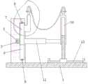
图1是烧伤患者用肢体支撑架的主视图;Fig. 1 is a front view of a limb support frame for burn patients;
图2是烧伤患者用肢体支撑架的俯视图;Fig. 2 is a top view of a limb support frame for burn patients;
图3是连接座部位剖视放大图。Fig. 3 is an enlarged cross-sectional view of the connection seat.
底板1、固定座2、步进电机3、转轴4、齿轮5、滑槽6、齿条板7、第一行程开关8、第二行程开关9、避让孔10、连接座11、电动推杆12、滑轨13、第三行程开关14、第四行程开关15、滑座16、导向杆17、滑动套18、固定板19、卡套20、弹性布21、第一开关201、第二开关202、第三开关203、第四开关204、螺栓2001。Bottom plate 1,
如下具体实施方式将结合上述附图进一步说明。The following specific embodiments will be further described in conjunction with the above-mentioned drawings.
具体实施方式Detailed ways
在下文中,阐述了多种特定细节,以便提供对构成所描述实施例基础的概念的透彻理解,然而,对本领域的技术人员来说,很显然所描述的实施例可以在没有这些特定细节中的一些或者全部的情况下来实践,在其他情况下,没有具体描述众所周知的处理步骤。In the following text, numerous specific details are set forth in order to provide a thorough understanding of the concepts underlying the described embodiments, however, it will be apparent to those skilled in the art that the described embodiments can be used without these specific details. Some or all instances were practiced, and in other instances well-known process steps were not described in detail.
如图1、图2、图3所示,烧伤患者用肢体支撑架,包括底板1、固定座2、步进电机3、转轴4、齿轮5、滑槽6、齿条板7、第一行程开关8、第二行程开关9、避让孔10、连接座11、电动推杆12、滑轨13、第三行程开关14、第四行程开关15、滑座16、导向杆17、滑动套18、固定板19、卡套20、弹性布21,所述的固定座2位于底板1顶部左侧,所述的固定座2与底板1螺纹相连,所述的步进电机3位于固定座2前端中部,所述的步进电机3与固定座2螺纹相连,所述的转轴4位于步进电机3后端,所述的转轴4与步进电机3紧配相连,且所述的转轴5与固定座2转动相连,所述的齿轮5贯穿于转轴4,所述的齿轮5与转轴4紧配相连,所述的滑槽6位于固定座2内部右侧,所述的滑槽6为矩形凹槽,所述的齿条板7位于滑槽6内部,所述的齿条板7与固定座2滑动相连,且所述的齿条板7与齿轮5轮齿啮合相连,所述的第一行程开关8位于滑槽6顶端,所述的第一行程开关8与固定座2螺纹相连,且所述的第一行程开关8与步进电机3导线相连,所述的第二行程开关9位于滑槽6底端,所述的第二行程开关9与固定座2螺纹相连,且所述的第二行程开关9与步进电机3导线相连,所述的避让孔10位于固定座2内部右侧,所述的避让孔10为矩形通孔,所述的连接座11位于齿条板7右侧上端,所述的连接座11与齿条板7螺纹相连,且所述的连接座11与固定座2滑动相连,所述的电动推杆12位于齿条板7右侧下端,所述的电动推杆12与齿条板7螺纹相连,且所述的电动推杆12与固定座2滑动相连,所述的滑轨13位于底板1顶部右侧,所述的滑轨13与底板1螺纹相连,所述的第三行程开关14位于滑轨13左侧,所述的第三行程开关14与滑轨13螺纹相连,且所述的第三行程开关14与电动推杆12导线相连,所述的第四行程开关15位于滑轨13右侧,所述的第四行程开关15与滑轨13螺纹相连,且所述的第四行程开关15与电动推杆12导线相连,所述的滑座16位于滑轨13外壁上端,所述的滑座16与滑轨13滑动相连,所述的导向杆17位于滑座16顶部,所述的导向杆17与滑座16一体相连,所述的滑动套18位于导向杆17外壁,所述的滑动套18与导向杆17滑动相连,且所述的滑动套18与电动推杆12螺纹相连,所述的固定板19位于连接座11和滑动套18顶部,所述的固定板19分别与连接座11和滑动套18螺纹相连,所述的卡套20位于固定板19外壁,所述的卡套20与固定板19活动相连,所述的弹性布21位于卡套20两两之间,所述的弹性布21左右两端分别与卡套20胶水相连,所述的固定座2前端左侧还设有第一开关201,所述的第一开关201与固定座2螺纹相连,且所述的第一开关201与步进电机3和第一行程开关8导线相连,所述的固定座2前端左侧还设有第二开关202,所述的第二开关202与固定座2螺纹相连,且所述的第二开关202与步进电机3和第二行程开关9导线相连,所述的固定座2前端右侧还设有第三开关203,所述的第三开关203与固定座2螺纹相连,且所述的第三开关203与电动推杆12和第三行程开关14导线相连,所述的固定座2前端右侧还设有第四开关204,所述的第四开关204与固定座2螺纹相连,且所述的第四开关204与电动推杆12和第四行程开关15导线相连,所述的卡套20内部下端外侧还贯穿有螺栓2001,所述的螺栓2001与卡套20螺纹相连,且所述的螺栓2001与固定板19螺纹相连。As shown in Figure 1, Figure 2, and Figure 3, the limb support frame for burn patients includes a base plate 1, a fixed
该烧伤患者用肢体支撑架,当需要对患者烧伤肢体进行换药或检查等护理操作时,预先根据患者肢体抬高位置,若需要抬高该装置时,医护人员按住第一开关201,使步进电机3与第一行程开关8,即步进电机3驱动转轴4带动齿轮5同步逆时针旋转,此时通过齿轮5逆时针旋转的作用,使齿条板7顺着滑槽6带动连接座11同步作由下向上运动,同时,齿条板7带动电动推杆12联动滑动套18顺着导向杆17作由下向上运动,此时通过连接座11与滑动套18同步向上,从而实现了该装置的升高,当该装置高度到达医护人员所需后,松开第一开关201,即步进电机3停止工作并自锁固定,反之若步进电机3持续工作导致齿条板7向上触碰第一行程开关8时,第一行程开关8被触发,即通过第一行程开关8触发的作用,使步进电机3停止工作并自锁固定,若需要下降该装置时,医护人员按住第二开关202,使步进电机3与第二行程开关9,即步进电机3驱动转轴4带动齿轮5同步顺时针旋转,此时通过齿轮5顺时针旋转的作用,使齿条板7顺着滑槽6带动连接座11同步作由上向下运动,同时,齿条板7带动电动推杆12联动滑动套18顺着导向杆17作由上向下运动,此时通过连接座11与滑动套18同步向下,从而实现了该装置的降低,当该装置高度到达医护人员所需后,松开第二开关202,即步进电机3停止工作并自锁固定,反之若步进电机3持续工作导致齿条板7向下触碰第二行程开关9时,第二行程开关9被触发,即通过第二行程开关9触发的作用,使步进电机3停止工作并自锁固定,最终通过上述,从而达到对该装置高度升降调节目的,满足了不同患者肢体放置的需要,接着,医护人员再根据患者肢体上创口的位置以及完后皮肤组织的位置,对固定板19两两之间的间距进行调节,具体操作如下,当需要缩小固定板19两两间距时,医护人员按住第三开关203,使电动推杆12以及第三行程开关14同时开启,即电动推杆12带动滑动套18联动导向杆17连同滑座16顺着滑轨13作由右向左运动,即通过向左的作用,使固定板19两两间距得以缩短,当位置到达医护人员需要后,松开第三开关203,即电动推杆12停止工作并自锁固定,此外,若电动推杆12持续向左侧,当滑座16触碰到第三行程开关14时,第三行程开关14被触发,即通过第三行程开关14触发的作用,使电动推杆12停止工作并自锁固定,当需要扩大固定板19两两间距时,医护人员按住第四开关204,使电动推杆12以及第四行程开关15同时开启,即电动推杆12带动滑动套18联动导向杆17连同滑座16顺着滑轨13作由左向右运动,即通过向右的作用,使固定板19两两间距得以延长,当位置到达医护人员需要后,松开第四开关204,即电动推杆12停止工作并自锁固定,此外,若电动推杆12持续向右侧,当滑座16触碰到第四行程开关15时,第四行程开关15被触发,即通过第四行程开关15触发的作用,使电动推杆12停止工作并自锁固定,最终通过上述操作,从而能够达到对固定板19两两间距调节目的,接着,医护人员将卡套20插入固定板19外壁,然后旋转螺栓2001,当螺栓2001插入固定板19后,通过螺栓2001的作用,使卡套20与固定板19相连固定,最后医护人员可将患者患肢放置在卡套20上,此时因固定板19处于患肢完后皮肤组织下端,有效避免了对创口部位造成的伤害,同时,因弹性布21位于换药创口区域下端,即通过弹性布21的收集作用,能够避免药液或血液滴落到地面,即达到对周围环境的保护,同时,避让孔10是为了对电动推杆12以及连接座11进行避让。The limb support frame for burn patients, when it is necessary to perform nursing operations such as dressing changes or inspections on the burnt limbs of the patient, the position of the limbs of the patient should be raised in advance. The stepping
本发明不局限于上述具体的实施方式,本领域的普通技术人员从上述构思出发,不经过创造性的劳动,所做出的种种变换,均落在本发明的保护范围之内。The present invention is not limited to the above-mentioned specific implementation manners, and various transformations made by those skilled in the art starting from the above-mentioned ideas without creative work all fall within the scope of protection of the present invention.
Claims (6)
Priority Applications (1)
| Application Number | Priority Date | Filing Date | Title |
|---|---|---|---|
| CN201810041070.XACN108175613B (en) | 2018-01-16 | 2018-01-16 | Limb support frame for burn patients |
Applications Claiming Priority (1)
| Application Number | Priority Date | Filing Date | Title |
|---|---|---|---|
| CN201810041070.XACN108175613B (en) | 2018-01-16 | 2018-01-16 | Limb support frame for burn patients |
Publications (2)
| Publication Number | Publication Date |
|---|---|
| CN108175613A CN108175613A (en) | 2018-06-19 |
| CN108175613Btrue CN108175613B (en) | 2023-04-28 |
Family
ID=62550691
Family Applications (1)
| Application Number | Title | Priority Date | Filing Date |
|---|---|---|---|
| CN201810041070.XAExpired - Fee RelatedCN108175613B (en) | 2018-01-16 | 2018-01-16 | Limb support frame for burn patients |
Country Status (1)
| Country | Link |
|---|---|
| CN (1) | CN108175613B (en) |
Families Citing this family (2)
| Publication number | Priority date | Publication date | Assignee | Title |
|---|---|---|---|---|
| CN110037888A (en)* | 2019-04-03 | 2019-07-23 | 王顺达 | Chair bed convolution patient's lower limb auxiliary exercise device |
| CN110604664A (en)* | 2019-09-20 | 2019-12-24 | 肖聪 | A body position pad structure for tibial intramedullary nail surgery |
Citations (2)
| Publication number | Priority date | Publication date | Assignee | Title |
|---|---|---|---|---|
| WO2015139542A1 (en)* | 2014-03-21 | 2015-09-24 | 上海璟和技创机器人有限公司 | Rehabilitation training device |
| CN206391148U (en)* | 2016-08-04 | 2017-08-11 | 贾连锋 | A kind of surgical operation adjusts the device of limb angle |
Family Cites Families (9)
| Publication number | Priority date | Publication date | Assignee | Title |
|---|---|---|---|---|
| CN201624918U (en)* | 2010-02-22 | 2010-11-10 | 殷建新 | Support bracket used for changing dressing for patient with lower limb fracture |
| CN203154166U (en)* | 2013-04-08 | 2013-08-28 | 李涛 | Bed frame for treating leg injury |
| CN105078684A (en)* | 2014-05-04 | 2015-11-25 | 上海理工大学 | Electric leg carrying rack |
| US9545348B2 (en)* | 2014-07-14 | 2017-01-17 | Elaine L. Britton | Mattress with a rotating and waste elimination system |
| CN205339386U (en)* | 2016-01-14 | 2016-06-29 | 李强 | Therapentic equipment is raised to low limbs |
| CN205459103U (en)* | 2016-02-15 | 2016-08-17 | 重庆医科大学附属永川医院 | Clinostatism low limbs pressurized position sight glass |
| CN205598139U (en)* | 2016-03-22 | 2016-09-28 | 黄凤娇 | Low limbs lift adjustment ware |
| CN108652905A (en)* | 2016-08-04 | 2018-10-16 | 崔娟 | A kind of surgical operation adjusts the device of limb angle |
| CN107095758B (en)* | 2017-07-10 | 2019-04-30 | 中国人民解放军第四军医大学 | Multifunctional local burn dressing change isolation device |
- 2018
- 2018-01-16CNCN201810041070.XApatent/CN108175613B/ennot_activeExpired - Fee Related
Patent Citations (2)
| Publication number | Priority date | Publication date | Assignee | Title |
|---|---|---|---|---|
| WO2015139542A1 (en)* | 2014-03-21 | 2015-09-24 | 上海璟和技创机器人有限公司 | Rehabilitation training device |
| CN206391148U (en)* | 2016-08-04 | 2017-08-11 | 贾连锋 | A kind of surgical operation adjusts the device of limb angle |
Also Published As
| Publication number | Publication date |
|---|---|
| CN108175613A (en) | 2018-06-19 |
Similar Documents
| Publication | Publication Date | Title |
|---|---|---|
| CN107028758B (en) | A comprehensive acupuncture and massage treatment device | |
| CN107029396A (en) | Device for healing and training shoulder joint | |
| CN108175613B (en) | Limb support frame for burn patients | |
| CN108245393A (en) | A kind of Gastroenterology dept. flatulence therapeutic device | |
| CN210228560U (en) | Orthopedic nursing is with shallow of changing dressings | |
| CN115813696A (en) | Multifunctional examining bed | |
| CN204562658U (en) | It is nursing hospital bed that a kind of patient of convenience lies in that the head of a bed prevents patient from rolling down | |
| CN110393579A (en) | An interventional treatment device for medical bone tumor | |
| CN206675669U (en) | A kind of burn patients with dressing-changing mount approach | |
| CN108113841A (en) | A kind of interventional treatment pacemaker head bracket | |
| CN108042150A (en) | A kind of foldable ladder for CT examination bed | |
| CN220385269U (en) | Remote control loading type flat-plate lifting traditional Chinese medicine hot compress device | |
| CN111991111A (en) | A tissue retraction device used in oral surgery | |
| CN204501467U (en) | A kind of Novel ophthalmic surgical ventilating frame | |
| CN117398262A (en) | Surgical dressing change position changing device | |
| CN212067088U (en) | Head immobilization device for medical eye examination | |
| CN114191225B (en) | A device for treating burns and scalds in general surgery | |
| CN210991490U (en) | A breast surgery examination bed with drainage and fixation function | |
| CN211962514U (en) | A special automatic lifting surgical stand for radical mastectomy of breast cancer | |
| CN210991364U (en) | Novel orthopedics patient position nursing support | |
| CN209747141U (en) | nuclear medicine isolation screen | |
| CN219461803U (en) | Adjustable medical support capable of placing tray | |
| CN221013784U (en) | A dressing change nursing support | |
| CN221308706U (en) | Orthopedics nail taking device | |
| CN221600624U (en) | Moxibustion fixed frame |
Legal Events
| Date | Code | Title | Description |
|---|---|---|---|
| PB01 | Publication | ||
| PB01 | Publication | ||
| SE01 | Entry into force of request for substantive examination | ||
| SE01 | Entry into force of request for substantive examination | ||
| GR01 | Patent grant | ||
| GR01 | Patent grant | ||
| CF01 | Termination of patent right due to non-payment of annual fee | ||
| CF01 | Termination of patent right due to non-payment of annual fee | Granted publication date:20230428 |