CN108140675B - Semiconductor device and method for manufacturing the same - Google Patents
Semiconductor device and method for manufacturing the sameDownload PDFInfo
- Publication number
- CN108140675B CN108140675BCN201680059777.2ACN201680059777ACN108140675BCN 108140675 BCN108140675 BCN 108140675BCN 201680059777 ACN201680059777 ACN 201680059777ACN 108140675 BCN108140675 BCN 108140675B
- Authority
- CN
- China
- Prior art keywords
- layer
- electrode
- insulating layer
- gate electrode
- region
- Prior art date
- Legal status (The legal status is an assumption and is not a legal conclusion. Google has not performed a legal analysis and makes no representation as to the accuracy of the status listed.)
- Expired - Fee Related
Links
Images


Classifications
- H—ELECTRICITY
- H10—SEMICONDUCTOR DEVICES; ELECTRIC SOLID-STATE DEVICES NOT OTHERWISE PROVIDED FOR
- H10D—INORGANIC ELECTRIC SEMICONDUCTOR DEVICES
- H10D30/00—Field-effect transistors [FET]
- H10D30/60—Insulated-gate field-effect transistors [IGFET]
- H10D30/67—Thin-film transistors [TFT]
- H10D30/6757—Thin-film transistors [TFT] characterised by the structure of the channel, e.g. transverse or longitudinal shape or doping profile
- H—ELECTRICITY
- H01—ELECTRIC ELEMENTS
- H01L—SEMICONDUCTOR DEVICES NOT COVERED BY CLASS H10
- H01L21/00—Processes or apparatus adapted for the manufacture or treatment of semiconductor or solid state devices or of parts thereof
- H01L21/02—Manufacture or treatment of semiconductor devices or of parts thereof
- H01L21/04—Manufacture or treatment of semiconductor devices or of parts thereof the devices having potential barriers, e.g. a PN junction, depletion layer or carrier concentration layer
- H01L21/18—Manufacture or treatment of semiconductor devices or of parts thereof the devices having potential barriers, e.g. a PN junction, depletion layer or carrier concentration layer the devices having semiconductor bodies comprising elements of Group IV of the Periodic Table or AIIIBV compounds with or without impurities, e.g. doping materials
- H01L21/28—Manufacture of electrodes on semiconductor bodies using processes or apparatus not provided for in groups H01L21/20 - H01L21/268
- H—ELECTRICITY
- H10—SEMICONDUCTOR DEVICES; ELECTRIC SOLID-STATE DEVICES NOT OTHERWISE PROVIDED FOR
- H10D—INORGANIC ELECTRIC SEMICONDUCTOR DEVICES
- H10D30/00—Field-effect transistors [FET]
- H10D30/60—Insulated-gate field-effect transistors [IGFET]
- H10D30/67—Thin-film transistors [TFT]
- H—ELECTRICITY
- H10—SEMICONDUCTOR DEVICES; ELECTRIC SOLID-STATE DEVICES NOT OTHERWISE PROVIDED FOR
- H10D—INORGANIC ELECTRIC SEMICONDUCTOR DEVICES
- H10D30/00—Field-effect transistors [FET]
- H10D30/60—Insulated-gate field-effect transistors [IGFET]
- H10D30/67—Thin-film transistors [TFT]
- H10D30/6729—Thin-film transistors [TFT] characterised by the electrodes
- H10D30/673—Thin-film transistors [TFT] characterised by the electrodes characterised by the shapes, relative sizes or dispositions of the gate electrodes
- H10D30/6733—Multi-gate TFTs
- H—ELECTRICITY
- H10—SEMICONDUCTOR DEVICES; ELECTRIC SOLID-STATE DEVICES NOT OTHERWISE PROVIDED FOR
- H10D—INORGANIC ELECTRIC SEMICONDUCTOR DEVICES
- H10D30/00—Field-effect transistors [FET]
- H10D30/60—Insulated-gate field-effect transistors [IGFET]
- H10D30/67—Thin-film transistors [TFT]
- H10D30/6729—Thin-film transistors [TFT] characterised by the electrodes
- H10D30/6737—Thin-film transistors [TFT] characterised by the electrodes characterised by the electrode materials
- H10D30/6739—Conductor-insulator-semiconductor electrodes
- H—ELECTRICITY
- H10—SEMICONDUCTOR DEVICES; ELECTRIC SOLID-STATE DEVICES NOT OTHERWISE PROVIDED FOR
- H10D—INORGANIC ELECTRIC SEMICONDUCTOR DEVICES
- H10D30/00—Field-effect transistors [FET]
- H10D30/60—Insulated-gate field-effect transistors [IGFET]
- H10D30/67—Thin-film transistors [TFT]
- H10D30/674—Thin-film transistors [TFT] characterised by the active materials
- H10D30/6755—Oxide semiconductors, e.g. zinc oxide, copper aluminium oxide or cadmium stannate
- H—ELECTRICITY
- H10—SEMICONDUCTOR DEVICES; ELECTRIC SOLID-STATE DEVICES NOT OTHERWISE PROVIDED FOR
- H10D—INORGANIC ELECTRIC SEMICONDUCTOR DEVICES
- H10D62/00—Semiconductor bodies, or regions thereof, of devices having potential barriers
- H10D62/40—Crystalline structures
- H10D62/402—Amorphous materials
- H—ELECTRICITY
- H10—SEMICONDUCTOR DEVICES; ELECTRIC SOLID-STATE DEVICES NOT OTHERWISE PROVIDED FOR
- H10D—INORGANIC ELECTRIC SEMICONDUCTOR DEVICES
- H10D62/00—Semiconductor bodies, or regions thereof, of devices having potential barriers
- H10D62/40—Crystalline structures
- H10D62/405—Orientations of crystalline planes
- H—ELECTRICITY
- H10—SEMICONDUCTOR DEVICES; ELECTRIC SOLID-STATE DEVICES NOT OTHERWISE PROVIDED FOR
- H10D—INORGANIC ELECTRIC SEMICONDUCTOR DEVICES
- H10D62/00—Semiconductor bodies, or regions thereof, of devices having potential barriers
- H10D62/80—Semiconductor bodies, or regions thereof, of devices having potential barriers characterised by the materials
- H—ELECTRICITY
- H10—SEMICONDUCTOR DEVICES; ELECTRIC SOLID-STATE DEVICES NOT OTHERWISE PROVIDED FOR
- H10D—INORGANIC ELECTRIC SEMICONDUCTOR DEVICES
- H10D64/00—Electrodes of devices having potential barriers
- H10D64/20—Electrodes characterised by their shapes, relative sizes or dispositions
- H10D64/27—Electrodes not carrying the current to be rectified, amplified, oscillated or switched, e.g. gates
- H10D64/311—Gate electrodes for field-effect devices
- H10D64/411—Gate electrodes for field-effect devices for FETs
- H10D64/511—Gate electrodes for field-effect devices for FETs for IGFETs
- H10D64/514—Gate electrodes for field-effect devices for FETs for IGFETs characterised by the insulating layers
- H—ELECTRICITY
- H10—SEMICONDUCTOR DEVICES; ELECTRIC SOLID-STATE DEVICES NOT OTHERWISE PROVIDED FOR
- H10D—INORGANIC ELECTRIC SEMICONDUCTOR DEVICES
- H10D64/00—Electrodes of devices having potential barriers
- H10D64/20—Electrodes characterised by their shapes, relative sizes or dispositions
- H10D64/27—Electrodes not carrying the current to be rectified, amplified, oscillated or switched, e.g. gates
- H10D64/311—Gate electrodes for field-effect devices
- H10D64/411—Gate electrodes for field-effect devices for FETs
- H10D64/511—Gate electrodes for field-effect devices for FETs for IGFETs
- H10D64/517—Gate electrodes for field-effect devices for FETs for IGFETs characterised by the conducting layers
- H—ELECTRICITY
- H10—SEMICONDUCTOR DEVICES; ELECTRIC SOLID-STATE DEVICES NOT OTHERWISE PROVIDED FOR
- H10D—INORGANIC ELECTRIC SEMICONDUCTOR DEVICES
- H10D64/00—Electrodes of devices having potential barriers
- H10D64/60—Electrodes characterised by their materials
- H10D64/66—Electrodes having a conductor capacitively coupled to a semiconductor by an insulator, e.g. MIS electrodes
- H—ELECTRICITY
- H10—SEMICONDUCTOR DEVICES; ELECTRIC SOLID-STATE DEVICES NOT OTHERWISE PROVIDED FOR
- H10D—INORGANIC ELECTRIC SEMICONDUCTOR DEVICES
- H10D84/00—Integrated devices formed in or on semiconductor substrates that comprise only semiconducting layers, e.g. on Si wafers or on GaAs-on-Si wafers
- H10D84/01—Manufacture or treatment
- H10D84/0123—Integrating together multiple components covered by H10D12/00 or H10D30/00, e.g. integrating multiple IGBTs
- H10D84/0126—Integrating together multiple components covered by H10D12/00 or H10D30/00, e.g. integrating multiple IGBTs the components including insulated gates, e.g. IGFETs
- H10D84/0128—Manufacturing their channels
- H—ELECTRICITY
- H10—SEMICONDUCTOR DEVICES; ELECTRIC SOLID-STATE DEVICES NOT OTHERWISE PROVIDED FOR
- H10D—INORGANIC ELECTRIC SEMICONDUCTOR DEVICES
- H10D84/00—Integrated devices formed in or on semiconductor substrates that comprise only semiconducting layers, e.g. on Si wafers or on GaAs-on-Si wafers
- H10D84/01—Manufacture or treatment
- H10D84/02—Manufacture or treatment characterised by using material-based technologies
- H10D84/03—Manufacture or treatment characterised by using material-based technologies using Group IV technology, e.g. silicon technology or silicon-carbide [SiC] technology
- H10D84/038—Manufacture or treatment characterised by using material-based technologies using Group IV technology, e.g. silicon technology or silicon-carbide [SiC] technology using silicon technology, e.g. SiGe
- H—ELECTRICITY
- H10—SEMICONDUCTOR DEVICES; ELECTRIC SOLID-STATE DEVICES NOT OTHERWISE PROVIDED FOR
- H10D—INORGANIC ELECTRIC SEMICONDUCTOR DEVICES
- H10D84/00—Integrated devices formed in or on semiconductor substrates that comprise only semiconducting layers, e.g. on Si wafers or on GaAs-on-Si wafers
- H10D84/80—Integrated devices formed in or on semiconductor substrates that comprise only semiconducting layers, e.g. on Si wafers or on GaAs-on-Si wafers characterised by the integration of at least one component covered by groups H10D12/00 or H10D30/00, e.g. integration of IGFETs
- H10D84/82—Integrated devices formed in or on semiconductor substrates that comprise only semiconducting layers, e.g. on Si wafers or on GaAs-on-Si wafers characterised by the integration of at least one component covered by groups H10D12/00 or H10D30/00, e.g. integration of IGFETs of only field-effect components
- H10D84/83—Integrated devices formed in or on semiconductor substrates that comprise only semiconducting layers, e.g. on Si wafers or on GaAs-on-Si wafers characterised by the integration of at least one component covered by groups H10D12/00 or H10D30/00, e.g. integration of IGFETs of only field-effect components of only insulated-gate FETs [IGFET]
- H—ELECTRICITY
- H10—SEMICONDUCTOR DEVICES; ELECTRIC SOLID-STATE DEVICES NOT OTHERWISE PROVIDED FOR
- H10D—INORGANIC ELECTRIC SEMICONDUCTOR DEVICES
- H10D86/00—Integrated devices formed in or on insulating or conducting substrates, e.g. formed in silicon-on-insulator [SOI] substrates or on stainless steel or glass substrates
- H10D86/40—Integrated devices formed in or on insulating or conducting substrates, e.g. formed in silicon-on-insulator [SOI] substrates or on stainless steel or glass substrates characterised by multiple TFTs
- H10D86/421—Integrated devices formed in or on insulating or conducting substrates, e.g. formed in silicon-on-insulator [SOI] substrates or on stainless steel or glass substrates characterised by multiple TFTs having a particular composition, shape or crystalline structure of the active layer
- H10D86/423—Integrated devices formed in or on insulating or conducting substrates, e.g. formed in silicon-on-insulator [SOI] substrates or on stainless steel or glass substrates characterised by multiple TFTs having a particular composition, shape or crystalline structure of the active layer comprising semiconductor materials not belonging to the Group IV, e.g. InGaZnO
- H—ELECTRICITY
- H10—SEMICONDUCTOR DEVICES; ELECTRIC SOLID-STATE DEVICES NOT OTHERWISE PROVIDED FOR
- H10D—INORGANIC ELECTRIC SEMICONDUCTOR DEVICES
- H10D86/00—Integrated devices formed in or on insulating or conducting substrates, e.g. formed in silicon-on-insulator [SOI] substrates or on stainless steel or glass substrates
- H10D86/40—Integrated devices formed in or on insulating or conducting substrates, e.g. formed in silicon-on-insulator [SOI] substrates or on stainless steel or glass substrates characterised by multiple TFTs
- H10D86/471—Integrated devices formed in or on insulating or conducting substrates, e.g. formed in silicon-on-insulator [SOI] substrates or on stainless steel or glass substrates characterised by multiple TFTs having different architectures, e.g. having both top-gate and bottom-gate TFTs
- H—ELECTRICITY
- H10—SEMICONDUCTOR DEVICES; ELECTRIC SOLID-STATE DEVICES NOT OTHERWISE PROVIDED FOR
- H10D—INORGANIC ELECTRIC SEMICONDUCTOR DEVICES
- H10D86/00—Integrated devices formed in or on insulating or conducting substrates, e.g. formed in silicon-on-insulator [SOI] substrates or on stainless steel or glass substrates
- H10D86/40—Integrated devices formed in or on insulating or conducting substrates, e.g. formed in silicon-on-insulator [SOI] substrates or on stainless steel or glass substrates characterised by multiple TFTs
- H10D86/60—Integrated devices formed in or on insulating or conducting substrates, e.g. formed in silicon-on-insulator [SOI] substrates or on stainless steel or glass substrates characterised by multiple TFTs wherein the TFTs are in active matrices
- H—ELECTRICITY
- H10—SEMICONDUCTOR DEVICES; ELECTRIC SOLID-STATE DEVICES NOT OTHERWISE PROVIDED FOR
- H10D—INORGANIC ELECTRIC SEMICONDUCTOR DEVICES
- H10D99/00—Subject matter not provided for in other groups of this subclass
- H—ELECTRICITY
- H10—SEMICONDUCTOR DEVICES; ELECTRIC SOLID-STATE DEVICES NOT OTHERWISE PROVIDED FOR
- H10K—ORGANIC ELECTRIC SOLID-STATE DEVICES
- H10K59/00—Integrated devices, or assemblies of multiple devices, comprising at least one organic light-emitting element covered by group H10K50/00
- H10K59/10—OLED displays
- H10K59/12—Active-matrix OLED [AMOLED] displays
- H10K59/121—Active-matrix OLED [AMOLED] displays characterised by the geometry or disposition of pixel elements
- H10K59/1213—Active-matrix OLED [AMOLED] displays characterised by the geometry or disposition of pixel elements the pixel elements being TFTs
Landscapes
- Engineering & Computer Science (AREA)
- Physics & Mathematics (AREA)
- Microelectronics & Electronic Packaging (AREA)
- Geometry (AREA)
- Condensed Matter Physics & Semiconductors (AREA)
- General Physics & Mathematics (AREA)
- Manufacturing & Machinery (AREA)
- Computer Hardware Design (AREA)
- Power Engineering (AREA)
- Thin Film Transistor (AREA)
Abstract
Translated fromChinese
Description
Translated fromChinese技术领域technical field
本发明涉及半导体装置及其制造方法。The present invention relates to a semiconductor device and a method of manufacturing the same.
背景技术Background technique
有源矩阵基板按每一像素具备例如薄膜晶体管(Thin Film Transistor;以下为“TFT”)作为开关元件。在本说明书中,将这种 TFT称为“像素TFT”。作为像素TFT,以往以来广泛地使用以非晶硅 膜为活性层的非晶硅TFT、以多晶硅膜等结晶质硅膜为活性层的结晶质硅TFT。The active matrix substrate includes, for example, a thin film transistor (Thin Film Transistor; hereinafter "TFT") as a switching element for each pixel. In this specification, such a TFT is referred to as a "pixel TFT". As pixel TFTs, amorphous silicon TFTs using an amorphous silicon film as an active layer and crystalline silicon TFTs using a crystalline silicon film such as a polycrystalline silicon film as an active layer have been widely used.
有时也在与像素TFT相同的基板上一体地形成周边驱动电路的 一部分或整体。这种有源矩阵基板被称为驱动单片的有源矩阵基板。 在驱动单片的有源矩阵基板中,周边驱动电路设于包含多个像素的 区域(显示区域)以外的区域(非显示区域或边框区域)。像素TFT 和构成驱动电路的TFT(驱动TFT)可使用相同的半导体膜来形成。 作为该半导体膜,例如能使用电场效应迁移率高的多晶硅膜。In some cases, a part or the whole of the peripheral driver circuit is integrally formed on the same substrate as the pixel TFT. Such an active matrix substrate is called a driving monolithic active matrix substrate. In a single-chip active matrix substrate, peripheral drive circuits are provided in regions (non-display regions or frame regions) other than regions (display regions) including a plurality of pixels. The pixel TFT and the TFT (driving TFT) constituting the driving circuit can be formed using the same semiconductor film. As the semiconductor film, for example, a polysilicon film having a high field effect mobility can be used.
另外,作为TFT的活性层的材料,已提出使用氧化物半导体来代 替非晶硅或多晶硅。作为氧化物半导体,例如还提出了使用以铟、 镓、锌和氧为主要成分的In-Ga-Zn-O系半导体。将这种TFT称为“氧 化物半导体TFT”。氧化物半导体具有比非晶硅高的迁移率。因此,氧化物半导体TFT能按比非晶硅TFT高的速度动作。另外,氧化物半 导体膜用比多晶硅膜简便的工艺形成,因此还能应用于需要大面积 的装置。In addition, as the material of the active layer of the TFT, it has been proposed to use an oxide semiconductor instead of amorphous silicon or polycrystalline silicon. As the oxide semiconductor, for example, it has been proposed to use an In-Ga-Zn-O-based semiconductor mainly composed of indium, gallium, zinc, and oxygen. Such a TFT is called an "oxide semiconductor TFT". Oxide semiconductors have higher mobility than amorphous silicon. Therefore, the oxide semiconductor TFT can operate at a higher speed than the amorphous silicon TFT. In addition, since the oxide semiconductor film is formed by a simpler process than that of the polysilicon film, it can also be applied to a device requiring a large area.
在氧化物半导体TFT中,若在从基板的法线方向观看时,栅极电 极与源极电极或漏极电极重叠,则根据其重叠面积而在栅极/源极间 以及栅极/漏极间形成寄生电容。当寄生电容大时,氧化物半导体TFT 的动作速度有可能下降。In an oxide semiconductor TFT, when the gate electrode overlaps with the source electrode or the drain electrode when viewed from the normal direction of the substrate, the gap between the gate and the source and between the gate and the drain depends on the overlapping area. A parasitic capacitance is formed between them. When the parasitic capacitance is large, the operating speed of the oxide semiconductor TFT may decrease.
因此,提出了具有将栅极电极与源极电极/漏极电极分开配置的、 所谓的偏置结构的TFT。具有偏置结构的TFT在形成氧化物半导体层 的沟道的部分(以下称为“沟道形成区域”。)具有不隔着栅极绝缘 膜与栅极电极重叠的区域(偏置区域)。在沟道蚀刻型的TFT中,氧 化物半导体层的沟道形成区域中的与源极电极、漏极电极以及栅极 电极均不重叠的区域成为“偏置区域”。此外,“沟道形成区域”是 指位于氧化物半导体层中的连接到源极电极的源极接触区域和连接 到漏极电极的漏极接触区域之间的区域。Therefore, a TFT having a so-called bias structure in which the gate electrode and the source/drain electrodes are arranged separately has been proposed. The TFT having the bias structure has a region (offset region) that does not overlap with the gate electrode via the gate insulating film in the portion where the channel of the oxide semiconductor layer is formed (hereinafter referred to as "channel formation region"). In a channel-etched TFT, a region in the channel formation region of the oxide semiconductor layer that does not overlap with the source electrode, the drain electrode, and the gate electrode becomes the "offset region". Further, the "channel formation region" refers to a region located in the oxide semiconductor layer between the source contact region connected to the source electrode and the drain contact region connected to the drain electrode.
偏置区域是不与栅极电极相对,不会由于向栅极电极施加电压 而被低电阻化的区域。在具有偏置结构的TFT中,这种偏置区域配置 于氧化物半导体层的沟道形成区域,因此存在导通电流下降的问题。 特别是,在氧化物半导体TFT中,大多是截止泄漏特性优异但氧化物 半导体层的电阻高,因此当栅极电极与漏极电极的距离远时,有时 无法得到充分的导通特性。The bias region is not opposed to the gate electrode and is not reduced in resistance by applying a voltage to the gate electrode. In a TFT having a bias structure, since such a bias region is arranged in the channel formation region of the oxide semiconductor layer, there is a problem that the ON current is lowered. In particular, many oxide semiconductor TFTs have excellent off-leakage characteristics, but the resistance of the oxide semiconductor layer is high. Therefore, when the distance between the gate electrode and the drain electrode is long, sufficient on-state characteristics may not be obtained.
对此,例如专利文献1公开了为了提高具有偏置结构的氧化物半 导体TFT的电特性而以与偏置区域对应的方式设置辅助栅极电极。在 专利文献1公开的底栅型的氧化物半导体TFT中,在覆盖TFT的保护 层上的与氧化物半导体层的偏置区域对应的位置配置有辅助栅极电 极。In this regard, for example, Patent Document 1 discloses that an auxiliary gate electrode is provided so as to correspond to the offset region in order to improve the electrical characteristics of the oxide semiconductor TFT having the offset structure. In the bottom-gate oxide semiconductor TFT disclosed in Patent Document 1, an auxiliary gate electrode is arranged on a protective layer covering the TFT at a position corresponding to an offset region of the oxide semiconductor layer.
现有技术文献prior art literature
专利文献Patent Literature
专利文献1:特开2011-82486号公报Patent Document 1: Japanese Patent Laid-Open No. 2011-82486
发明内容SUMMARY OF THE INVENTION
发明要解决的问题Invention to solve problem
本发明的发明人研究后发现,专利文献1中公开的TFT结构有时 无法得到充分的可靠性。后面详细描述。The inventors of the present invention have found that the TFT structure disclosed in Patent Document 1 cannot obtain sufficient reliability in some cases. Described in detail later.
本发明的一实施方式是鉴于上述情况而完成的,其目的在于提 供具备氧化物半导体TFT且TFT特性和可靠性优异的半导体装置及 其制造方法。One embodiment of the present invention has been made in view of the above-mentioned circumstances, and an object thereof is to provide a semiconductor device including an oxide semiconductor TFT and having excellent TFT characteristics and reliability, and a method for manufacturing the same.
用于解决问题的方案solution to the problem
本发明的一实施方式的半导体装置是具备基板和设置在上述基 板上的第1薄膜晶体管的半导体装置,上述第1薄膜晶体管具有:至 少1个副栅极电极;第1绝缘层,其覆盖上述副栅极电极;主栅极电 极,其形成于上述第1绝缘层上;第2绝缘层,其覆盖上述主栅极电 极;氧化物半导体层,其以隔着上述第2绝缘层与上述主栅极电极局 部重叠的方式配置,具有包含第1层和第2层的层叠结构,上述第2层 设置在上述第1层上,与上述第1层相比带隙较大;以及第1源极电极 及第1漏极电极,其电连接到上述氧化物半导体层,上述氧化物半导 体层包括:栅极相对区域,其当从基板法线方向观看时与上述主栅 极电极重叠;源极接触区域,其与上述第1源极电极接触;漏极接触 区域,其与上述第1漏极电极接触;以及偏置区域,其设于上述栅极 相对区域与上述源极接触区域之间和上述栅极相对区域与上述漏极 接触区域之间中的至少一方,上述偏置区域的至少一部分隔着上述 第1绝缘层和上述第2绝缘层与上述副栅极电极重叠。A semiconductor device according to an embodiment of the present invention is a semiconductor device including a substrate and a first thin film transistor provided on the substrate, wherein the first thin film transistor includes: at least one sub-gate electrode; and a first insulating layer covering the above-mentioned a sub-gate electrode; a main gate electrode formed on the first insulating layer; a second insulating layer covering the main gate electrode; an oxide semiconductor layer connected to the main gate electrode via the second insulating layer The gate electrodes are arranged so as to partially overlap, and have a stacked structure including a first layer and a second layer, the second layer is provided on the first layer and has a larger band gap than the first layer; and a first source A pole electrode and a first drain electrode, which are electrically connected to the oxide semiconductor layer, the oxide semiconductor layer including: a gate opposing region overlapping the main gate electrode when viewed from the substrate normal direction; a source electrode a contact region in contact with the first source electrode; a drain contact region in contact with the first drain electrode; and a bias region provided between and between the gate opposing region and the source contact region At least one of the gate opposing region and the drain contact region, and at least a part of the offset region overlaps the sub-gate electrode via the first insulating layer and the second insulating layer.
在某实施方式中可以是,当从上述基板的法线方向观看时,上 述偏置区域与上述栅极相对区域相邻设置,并且与上述主栅极电极、 上述第1源极电极以及上述第1漏极电极均不重叠。In one embodiment, when viewed from the normal direction of the substrate, the offset region may be provided adjacent to the gate opposing region, and may be adjacent to the main gate electrode, the first source electrode, and the first source electrode. 1 None of the drain electrodes overlap.
在某实施方式中,上述偏置区域包括:配置在上述栅极相对区 域和上述源极接触区域之间的源极侧偏置区域;以及配置在上述栅 极相对区域和上述漏极接触区域之间的漏极侧偏置区域,上述副栅 极电极包括:隔着上述第1绝缘层和上述第2绝缘层与上述源极侧偏 置区域的至少一部分重叠的源极侧副栅极电极;以及与上述漏极侧 偏置区域的至少一部分重叠的漏极侧副栅极电极,当从上述基板的 法线方向观看时,上述源极侧副栅极电极和上述漏极侧副栅极电极 在上述主栅极电极的下方分开配置。In one embodiment, the bias region includes: a source side bias region arranged between the gate opposing region and the source contact region; and a source side bias region arranged between the gate opposing region and the drain contact region a drain-side bias region between the two, the sub-gate electrode including: a source-side sub-gate electrode overlapping at least a part of the source-side bias region with the first insulating layer and the second insulating layer interposed therebetween; and a drain-side sub-gate electrode overlapping at least a part of the drain-side bias region, the source-side sub-gate electrode and the drain-side sub-gate electrode when viewed from the normal direction of the substrate They are arranged separately below the main gate electrode.
在某实施方式中,当从上述基板的法线方向观看时,上述副栅 极电极与上述第1源极电极和上述第1漏极电极中的任意一方重叠, 上述副栅极电极中的、与上述第1源极电极或上述第1漏极电极重叠 的部分的沟道长度方向的长度是0μm以上1μm以下。In one embodiment, the sub-gate electrode overlaps with any one of the first source electrode and the first drain electrode when viewed from the normal direction of the substrate, and among the sub-gate electrodes, The length in the channel length direction of the portion overlapping the first source electrode or the first drain electrode is 0 μm or more and 1 μm or less.
在某实施方式中,当从上述基板的法线方向观看时,上述副栅 极电极与上述主栅极电极的上述第1源极电极侧的端部和上述第1漏 极电极侧的端部中的任意一方重叠,上述副栅极电极中的、与上述 主栅极电极的上述第1源极电极侧的端部或上述第1漏极电极侧的端 部重叠的部分的沟道长度方向的长度是0μm以上1μm以下。In one embodiment, when viewed from the normal direction of the substrate, the sub-gate electrode and the main gate electrode have an end on the first source electrode side and an end on the first drain electrode side. Either one of the sub-gate electrodes overlaps with the end portion on the first source electrode side or the end portion on the first drain electrode side of the main gate electrode in the channel length direction of the portion The length is 0 μm or more and 1 μm or less.
在某实施方式中,上述半导体装置还具备支撑于上述基板的第2 薄膜晶体管,上述第2薄膜晶体管具有:结晶质硅半导体层,其主要 包含结晶质硅;第3绝缘层,其覆盖上述结晶质硅半导体层;第2栅 极电极,其以隔着上述第3绝缘层与上述结晶质硅半导体层的至少一 部分重叠的方式配置于上述第3绝缘层上;以及第2源极电极及第2漏 极电极,其与上述结晶质硅半导体层电连接,上述第1薄膜晶体管的 上述主栅极电极和上述第2薄膜晶体管的上述第2栅极电极设于不同 的层。In one embodiment, the semiconductor device further includes a second thin film transistor supported by the substrate, and the second thin film transistor includes: a crystalline silicon semiconductor layer mainly including crystalline silicon; and a third insulating layer covering the crystal a crystalline silicon semiconductor layer; a second gate electrode disposed on the third insulating layer so as to overlap at least a part of the crystalline silicon semiconductor layer with the third insulating layer interposed therebetween; and a second source electrode and a third 2 drain electrodes electrically connected to the crystalline silicon semiconductor layer, wherein the main gate electrode of the first thin film transistor and the second gate electrode of the second thin film transistor are provided in different layers.
在某实施方式中,上述第2薄膜晶体管的上述第2栅极电极和上 述第1薄膜晶体管的上述副栅极电极形成于相同的层内,上述第1绝 缘层延伸设置到上述第2薄膜晶体管的上述第2栅极电极上。In one embodiment, the second gate electrode of the second thin film transistor and the sub-gate electrode of the first thin film transistor are formed in the same layer, and the first insulating layer is extended to the second thin film transistor on the above-mentioned second gate electrode.
在某实施方式中,上述第2薄膜晶体管的上述第2源极电极和上 述第2漏极电极形成于与上述第1薄膜晶体管的上述主栅极电极相同 的层内,上述第2源极电极和上述第2漏极电极在形成于上述第1绝缘 层和上述第3绝缘层的接触孔内与上述结晶质硅半导体层接触。In one embodiment, the second source electrode and the second drain electrode of the second thin film transistor are formed in the same layer as the main gate electrode of the first thin film transistor, and the second source electrode is formed in the same layer as the main gate electrode of the first thin film transistor. and the second drain electrode is in contact with the crystalline silicon semiconductor layer in the contact hole formed in the first insulating layer and the third insulating layer.
在某实施方式中,上述第2薄膜晶体管的上述第2源极电极和上 述第2漏极电极形成于与上述第1薄膜晶体管的上述第1源极电极和 上述第1漏极电极相同的层内,上述第2源极电极和上述第2漏极电极 在形成于上述第2绝缘层、上述第1绝缘层和上述第3绝缘层的接触孔 内与上述结晶质硅半导体层接触。In one embodiment, the second source electrode and the second drain electrode of the second thin film transistor are formed in the same layer as the first source electrode and the first drain electrode of the first thin film transistor. Inside, the second source electrode and the second drain electrode are in contact with the crystalline silicon semiconductor layer in contact holes formed in the second insulating layer, the first insulating layer, and the third insulating layer.
在某实施方式中,上述半导体装置还具备具有多个像素的显示 区域、以及设于上述显示区域以外的区域并具有驱动电路的驱动电 路区域,上述第1薄膜晶体管配置于上述显示区域的各像素,上述第 2薄膜晶体管在上述驱动电路区域中构成上述驱动电路。In one embodiment, the semiconductor device further includes a display area having a plurality of pixels, and a driver circuit area provided in an area other than the display area and having a driver circuit, and the first thin film transistor is arranged in each pixel of the display area and the second thin film transistor constitutes the drive circuit in the drive circuit region.
在某实施方式中,上述第1薄膜晶体管具有沟道蚀刻结构。In one embodiment, the first thin film transistor has a channel-etched structure.
在某实施方式中,上述氧化物半导体层包含In-Ga-Zn-O系半导体。In one embodiment, the oxide semiconductor layer includes an In-Ga-Zn-O-based semiconductor.
在某实施方式中,上述氧化物半导体层包含结晶质部分。In one embodiment, the oxide semiconductor layer includes a crystalline portion.
本发明的一实施方式的半导体装置的制造方法是具备以氧化物 半导体层为活性层的第1薄膜晶体管和以结晶质硅半导体层为活性 层的第2薄膜晶体管的半导体装置的制造方法,包含:工序(A),在 基板上形成结晶质硅半导体层;工序(B),在上述结晶质硅半导体 层上形成第3绝缘层;工序(C),在上述第3绝缘层上形成副栅极用 导电膜,并对其进行图案化,从而形成上述第2薄膜晶体管的栅极电 极和上述第1薄膜晶体管的副栅极电极;工序(D),形成将上述第2 薄膜晶体管的上述栅极电极和上述第1薄膜晶体管的上述副栅极电极覆盖的第1绝缘层,在上述第3绝缘层和上述第1绝缘层中形成将上 述结晶质硅半导体层的一部分露出的源极接触孔和漏极接触孔;在 上述第1绝缘层上、上述源极接触孔内以及上述漏极接触孔内形成主 栅极用导电膜,并对其进行图案化,从而形成上述第2薄膜晶体管的 源极电极及漏极电极和上述第1薄膜晶体管的主栅极电极的工序,其 中,上述第2薄膜晶体管的源极电极及漏极电极分别在上述源极接触 孔和上述漏极接触孔内与上述结晶质硅半导体层接触;工序(E), 形成将上述第2薄膜晶体管的上述源极电极及漏极电极和上述第1薄 膜晶体管的上述主栅极电极覆盖的第2绝缘层;工序(F),在上述第 2绝缘层上以隔着上述第2绝缘层与上述主栅极电极局部重叠的方式 形成氧化物半导体层,其中,上述氧化物半导体层具有包含第1层和 第2层的层叠结构,上述第2层配置于上述第1层上,与上述第1层相 比带隙较大;以及工序(G),以与上述氧化物半导体层的一部分接 触的方式形成上述第1薄膜晶体管的源极电极,以与上述氧化物半导 体层的另一部分接触的方式形成上述第1薄膜晶体管的漏极电极,当 从基板法线方向观看时,若将上述氧化物半导体层中的与上述主栅 极电极重叠的部分设为栅极相对区域、将与上述源极电极接触的部 分设为源极接触区域、将与上述漏极电极接触的部分设为漏极接触 区域,则上述氧化物半导体层包含设于上述栅极相对区域与上述源 极接触区域之间和上述栅极相对区域与上述漏极接触区域之间中的 至少一方的偏置区域,上述偏置区域的至少一部分隔着上述第1绝缘 层和上述第2绝缘层与上述副栅极电极重叠。A method of manufacturing a semiconductor device according to an embodiment of the present invention is a method of manufacturing a semiconductor device including a first thin film transistor including an oxide semiconductor layer as an active layer and a second thin film transistor including a crystalline silicon semiconductor layer as an active layer, including Step (A), forming a crystalline silicon semiconductor layer on the substrate; step (B), forming a third insulating layer on the crystalline silicon semiconductor layer; step (C), forming a sub-gate on the third insulating layer electrode conductive film, and patterning it to form the gate electrode of the second thin film transistor and the sub-gate electrode of the first thin film transistor; step (D), forming the gate electrode of the second thin film transistor a first insulating layer covering the electrode electrode and the sub-gate electrode of the first thin film transistor, a source contact hole exposing a part of the crystalline silicon semiconductor layer is formed in the third insulating layer and the first insulating layer and a drain contact hole; a conductive film for the main gate is formed on the first insulating layer, in the source contact hole and in the drain contact hole, and patterned to form the second thin film transistor. The source electrode and the drain electrode and the main gate electrode of the first thin film transistor, wherein the source electrode and the drain electrode of the second thin film transistor are in the source contact hole and the drain contact hole, respectively. contacting the crystalline silicon semiconductor layer; step (E), forming a second insulating layer covering the source electrode and drain electrode of the second thin film transistor and the main gate electrode of the first thin film transistor; step (F) forming an oxide semiconductor layer on the second insulating layer so as to partially overlap the main gate electrode with the second insulating layer interposed therebetween, wherein the oxide semiconductor layer includes a first layer and a second layer A layered structure in which the second layer is disposed on the first layer and has a larger band gap than the first layer; and step (G), in which the first layer is formed in contact with a part of the oxide semiconductor layer. 1 The source electrode of the thin film transistor, the drain electrode of the first thin film transistor is formed so as to be in contact with the other part of the oxide semiconductor layer, when viewed from the substrate normal direction, if the oxide semiconductor layer is The portion overlapping the main gate electrode is referred to as a gate opposing region, the portion in contact with the source electrode is referred to as a source contact region, and the portion in contact with the drain electrode is referred to as a drain contact region, the above The oxide semiconductor layer includes an offset region provided at least one of between the gate opposing region and the source contact region and between the gate opposing region and the drain contact region, and at least a part of the offset region It overlaps with the said sub-gate electrode via the said 1st insulating layer and the said 2nd insulating layer.
本发明的另一实施方式的半导体装置的制造方法是具备以氧化 物半导体层为活性层的第1薄膜晶体管和以结晶质硅半导体层为活 性层的第2薄膜晶体管的半导体装置的制造方法,包含:工序(A), 在基板上形成结晶质硅半导体层;工序(B),在上述结晶质硅半导 体层上形成第3绝缘层;工序(C),在上述第3绝缘层上形成副栅极 用导电膜,并对其进行图案化,从而形成上述第2薄膜晶体管的栅极 电极和上述第1薄膜晶体管的副栅极电极;工序(D),形成将上述第 2薄膜晶体管的上述栅极电极和上述第1薄膜晶体管的上述副栅极电 极覆盖的第1绝缘层;在上述第1绝缘层上形成主栅极用导电膜,并 对其进行图案化,从而形成上述第1薄膜晶体管的主栅极电极的工 序;工序(E),形成将上述第1薄膜晶体管的上述主栅极电极覆盖的 第2绝缘层;工序(F),在上述第3绝缘层、上述第1绝缘层和上述第2绝缘层中形成将上述结晶质硅半导体层的一部分露出的源极接触 孔和漏极接触孔;工序(G),在上述第2绝缘层上以隔着上述第2绝 缘层与上述主栅极电极局部重叠的方式形成成为上述第1薄膜晶体 管的活性层的氧化物半导体层,其中,上述氧化物半导体层具有包 含第1层和第2层的层叠结构,上述第2层配置于上述第1层上,与上 述第1层相比带隙较大;以及工序(H),在上述第2绝缘层上、上述 氧化物半导体层上、上述源极接触孔内以及上述漏极接触孔内形成 源极用导电膜,并对其进行图案化,从而形成与上述氧化物半导体 层的一部分接触的上述第1薄膜晶体管的源极电极、与上述氧化物半 导体层的另一部分接触的上述第1薄膜晶体管的漏极电极、在上述源 极接触孔内与上述结晶质硅半导体层的一部分接触的上述第2薄膜 晶体管的源极电极、在上述漏极接触孔内与上述结晶质硅半导体层的另一部分接触的上述第2薄膜晶体管的漏极电极,当从基板法线方 向观看时,若将上述氧化物半导体层中的与上述主栅极电极重叠的 部分设为栅极相对区域、将与上述源极电极接触的部分设为源极接 触区域、将与上述漏极电极接触的部分设为漏极接触区域,则上述 氧化物半导体层包含设于上述栅极相对区域与上述源极接触区域之 间和上述栅极相对区域与上述漏极接触区域之间中的至少一方的偏 置区域,上述偏置区域的至少一部分隔着上述第1绝缘层和上述第2 绝缘层与上述副栅极电极重叠。A method of manufacturing a semiconductor device according to another embodiment of the present invention is a method of manufacturing a semiconductor device including a first thin film transistor having an oxide semiconductor layer as an active layer and a second thin film transistor having a crystalline silicon semiconductor layer as an active layer, including: a step (A) of forming a crystalline silicon semiconductor layer on a substrate; a step (B) of forming a third insulating layer on the crystalline silicon semiconductor layer; and a step (C) of forming a sub-layer on the third insulating layer and patterning the conductive film for the gate to form the gate electrode of the second thin film transistor and the sub-gate electrode of the first thin film transistor; step (D), forming the above-mentioned second thin film transistor A gate electrode and a first insulating layer covering the sub-gate electrode of the first thin film transistor; a conductive film for a main gate is formed on the first insulating layer and patterned to form the first thin film The process of the main gate electrode of the transistor; Step (E), forming a second insulating layer covering the main gate electrode of the first thin film transistor; Step (F), on the third insulating layer, the first insulating layer forming a source contact hole and a drain contact hole in the layer and the second insulating layer exposing a part of the crystalline silicon semiconductor layer; step (G), on the second insulating layer with the second insulating layer interposed therebetween An oxide semiconductor layer to be an active layer of the first thin film transistor is formed so as to partially overlap the main gate electrode, wherein the oxide semiconductor layer has a stacked structure including a first layer and a second layer, and the second layer is disposed on the first layer, and has a larger band gap than the first layer; and in step (H), on the second insulating layer, on the oxide semiconductor layer, in the source contact hole, and in the drain A source electrode conductive film is formed in the electrode contact hole and patterned to form the source electrode of the first thin film transistor in contact with a part of the oxide semiconductor layer and in contact with the other part of the oxide semiconductor layer. the drain electrode of the first thin film transistor, the source electrode of the second thin film transistor which is in contact with a part of the crystalline silicon semiconductor layer in the source contact hole, and the crystalline silicon semiconductor layer in the drain contact hole The drain electrode of the second thin film transistor, which is in contact with the other part of the silicon semiconductor layer, is viewed from the substrate normal direction, if the portion of the oxide semiconductor layer that overlaps the main gate electrode is assumed to be opposite to the gate. region, a portion in contact with the source electrode is referred to as a source contact region, and a portion in contact with the drain electrode is referred to as a drain contact region, and the oxide semiconductor layer includes a region provided in the gate opposing region and the At least one offset region between the source contact region and between the gate opposing region and the drain contact region, and at least a part of the offset region is connected to the first insulating layer and the second insulating layer via the first insulating layer and the second insulating layer. The sub-gate electrodes described above overlap.
在某实施方式中,上述第1薄膜晶体管具有沟道蚀刻结构。In one embodiment, the first thin film transistor has a channel-etched structure.
在某实施方式中,上述氧化物半导体层包含In-Ga-Zn-O系半导 体。In one embodiment, the oxide semiconductor layer includes an In-Ga-Zn-O-based semiconductor.
在某实施方式中,上述氧化物半导体层包含结晶质部分。In one embodiment, the oxide semiconductor layer includes a crystalline portion.
发明效果Invention effect
根据本发明的一实施方式,提供具备氧化物半导体TFT且TFT特 性和可靠性优异的半导体装置及其制造方法。According to an embodiment of the present invention, a semiconductor device including an oxide semiconductor TFT and having excellent TFT characteristics and reliability, and a method for manufacturing the same are provided.
附图说明Description of drawings
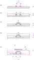
图1的(a)和(b)是例示第1实施方式的半导体装置的氧化物半 导体TFT101的截面图和俯视图。(a) and (b) of Fig. 1 are a cross-sectional view and a plan view illustrating an
图2是氧化物半导体TFT101的局部放大图。FIG. 2 is a partial enlarged view of the
图3的(a)~(e)分别是用于说明氧化物半导体TFT101的制造 方法的一例的工序截面图。(a) to (e) of FIG. 3 are process cross-sectional views for explaining an example of a method of manufacturing the
图4的(a)~(c)分别是用于说明氧化物半导体TFT101的制造 方法的一例的工序截面图。(a) to (c) of Fig. 4 are process cross-sectional views for explaining an example of a method of manufacturing the
图5是例示第2实施方式的半导体装置1001的示意性俯视图。FIG. 5 is a schematic plan view illustrating a
图6A是表示半导体装置1001的氧化物半导体TFT201和结晶质 硅TFT202的截面图。6A is a cross-sectional view showing an
图6B是结晶质硅TFT202的俯视图。FIG. 6B is a plan view of the
图6C是例示包含氧化物半导体TFT201的像素区域的俯视图。FIG. 6C is a plan view illustrating a pixel region including the
图6D是用于说明副栅极电极12与栅极配线G的连接结构的图,是 表示沿着图6C的A-A’线的截面的放大图。Fig. 6D is a diagram for explaining the connection structure between the
图7的(a)是表示比较例的半导体装置3000的氧化物半导体TF 和结晶质硅半导体TFT的截面图,(b)是比较例的半导体装置3000 的配线区域,(c)是示意性地例示第2实施方式的半导体装置1001的 配线区域的截面图。(a) of FIG. 7 is a cross-sectional view showing an oxide semiconductor TF and a crystalline silicon semiconductor TFT of the
图8的(a)~(d)分别是说明半导体装置1001的制造方法的示 意性工序截面图。(a) to (d) of FIG. 8 are schematic process cross-sectional views for explaining a method of manufacturing the
图9的(a)~(c)分别是说明半导体装置1001的制造方法的示 意性工序截面图。(a) to (c) of FIG. 9 are schematic process cross-sectional views for explaining a method of manufacturing the
图10的(a)和(b)分别是例示不具有偏置结构的氧化物半导 体TFT203的截面图和俯视图。(a) and (b) of Fig. 10 are a cross-sectional view and a top view, respectively, illustrating an
图11是第3实施方式的半导体装置1002的示意性截面图。11 is a schematic cross-sectional view of a
图12的(a)~(c)分别是说明半导体装置1002的制造方法的示 意性工序截面图。(a) to (c) of FIG. 12 are schematic process cross-sectional views illustrating a method of manufacturing the
图13是表示现有的氧化物半导体TFT2000的截面图。FIG. 13 is a cross-sectional view showing a conventional
具体实施方式Detailed ways
本发明的发明人针对具有偏置结构的现有的氧化物半导体TFT 反复研究的结果是,发现会产生如下问题。以下,参照附图进行说 明。The inventors of the present invention, as a result of repeated studies on the conventional oxide semiconductor TFT having an offset structure, found that the following problems arise. Hereinafter, description will be made with reference to the accompanying drawings.
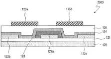
图13是表示专利文献1中公开的底栅型的氧化物半导体TFT2000 的截面图。FIG. 13 is a cross-sectional view showing a bottom-gate
氧化物半导体TFT2000具备:基板120;源极电极122b和漏极电 极122c,其形成于基板120上;栅极电极122a,其形成于源极电极122b 和漏极电极122c之间;栅极绝缘膜123,其覆盖栅极电极122a;氧化 物半导体层124,其以与源极电极122b和漏极电极122c接触的方式形 成在栅极绝缘膜123上;保护层125,其覆盖氧化物半导体层124;以 及辅助栅极电极126a、126b,其设于保护层125上。辅助栅极电极126a 以与氧化物半导体层124中的位于源极电极122b和栅极电极122a之 间的偏置区域对应的方式配置。同样地,辅助栅极电极126b以与位 于漏极电极122c和栅极电极122a之间的偏置区域对应的方式配置。The
在专利文献1公开的TFT结构中,辅助栅极电极126a、126b隔着 氧化物半导体层124配置于与栅极电极122a相反的一侧(后沟道侧)。In the TFT structure disclosed in Patent Document 1, the
另一方面,近年来,作为氧化物半导体层,提出了使用具有层 叠结构的氧化物半导体层(特开2013-038399号公报、特开 2014-033194号公报等)。例如作为底栅结构TFT的氧化物半导体层, 可使用在栅极绝缘膜上按顺序具有第1层以及与第1层相比能隙较大 的第2层的层叠半导体层。在该TFT中,沟道形成于带隙小的第1层。 电流难以流到作为后沟道侧的第2层,因此能抑制由电子陷阱等所致 的TFT的特性劣化。而且,在具有沟道蚀刻结构的TFT中,在源极/ 漏极分离工序中,还能使第2层作为缓冲层发挥功能,能抑制对作为 沟道形成区域的第1层的损伤。On the other hand, in recent years, use of an oxide semiconductor layer having a stacked structure has been proposed as an oxide semiconductor layer (Japanese Patent Laid-Open No. 2013-038399, Japanese Patent Laid-Open No. 2014-033194, etc.). For example, as the oxide semiconductor layer of the bottom gate structure TFT, a stacked semiconductor layer including a first layer and a second layer having a larger energy gap than the first layer on the gate insulating film can be used in this order. In this TFT, the channel is formed in the first layer with a small band gap. Since it is difficult for current to flow to the second layer on the back channel side, deterioration of the characteristics of the TFT due to electron traps and the like can be suppressed. Furthermore, in a TFT having a channel etched structure, the second layer can be made to function as a buffer layer in the source/drain separation step, and damage to the first layer as a channel formation region can be suppressed.
在专利文献1公开的TFT2000中,当应用如上所述的层叠半导体 层作为氧化物半导体层124时,由于配置在后沟道侧的辅助栅极电 极,电流还会流到层叠半导体层的后沟道侧(第2层侧)。其结果是, 有可能导致TFT特性劣化或者滞后增大。In the
另外,在专利文献1的TFT结构中,氧化物半导体TFT2000的保 护层125成为辅助栅极电极用的栅极绝缘膜(以下为“辅助栅极绝缘 膜”)。因此,难以将辅助栅极绝缘膜的条件最佳化。例如有可能无 法使辅助栅极绝缘膜足够薄而无法提高TFT的导通特性。另外,有时也无法使用具有最佳的性质的绝缘膜作为辅助栅极绝缘膜。一般地, 在氧化物半导体TFT的栅极绝缘膜中使用含氢率低的绝缘膜。其原因 是,当在氧化物半导体层中水分等杂质扩散时,会形成杂质能级而 载流子浓度变高,结果TFT特性发生变动,可能致使可靠性下降。但 是,例如适合作为平坦化膜即保护层125的绝缘膜有可能不具有辅助 栅极绝缘膜所要求的性质(例如低含氢率)。这样,无法以高自由度 选择辅助栅极绝缘膜的条件,其结果是,TFT的可靠性有可能下降。In addition, in the TFT structure of Patent Document 1, the protective layer 125 of the
本发明的发明人基于上述知识,在具备具有层叠结构的氧化物 半导体层作为活性层并且具有偏置结构的TFT中,发现了能确保可靠 性且能提高导通特性的结构,而想到了本申请发明。Based on the above knowledge, the inventors of the present invention found a structure that can ensure reliability and improve conduction characteristics in a TFT including an oxide semiconductor layer having a stacked structure as an active layer and a bias structure, and came up with the idea of the present invention. Apply for an invention.
(第1实施方式)(first embodiment)
以下说明本发明的半导体装置的第1实施方式。本实施方式的半 导体装置具备氧化物半导体TFT(以下简称为“TFT”。)。本实施方 式的半导体装置只要是在基板上具备至少1个TFT的装置即可,广泛 包括有源矩阵基板等电路基板、液晶显示装置或有机EL显示装置等 各种显示装置、图像传感器、电子设备等。A first embodiment of the semiconductor device of the present invention will be described below. The semiconductor device of the present embodiment includes an oxide semiconductor TFT (hereinafter abbreviated as "TFT"). The semiconductor device of the present embodiment only needs to be a device including at least one TFT on a substrate, and widely includes circuit substrates such as active matrix substrates, various display devices such as liquid crystal display devices and organic EL display devices, image sensors, and electronic equipment. Wait.
本实施方式的半导体装置的TFT具有偏置结构。另外,具有以与 氧化物半导体层相对的方式配置于相互不同的层内的2种栅极电极。 在本说明书中,将这些栅极电极中的、设于离氧化物半导体层近的 层的(即栅极绝缘膜的厚度较小的)栅极电极称为“主栅极电极”, 将设于离氧化物半导体层远的层的(即栅极绝缘膜的厚度较大的) 栅极电极称为“副栅极电极”。The TFT of the semiconductor device of this embodiment has a bias structure. In addition, there are two types of gate electrodes arranged in mutually different layers so as to face the oxide semiconductor layer. In this specification, among these gate electrodes, the gate electrode provided in the layer closer to the oxide semiconductor layer (that is, the gate insulating film having a smaller thickness) is referred to as the "main gate electrode", and the The gate electrode in the layer farther from the oxide semiconductor layer (ie, the thickness of the gate insulating film) is called "sub-gate electrode".
在本实施方式的半导体装置是有源矩阵基板的情况下,主栅极 电极连接到例如栅极总线。主栅极电极可以设于与栅极总线相同的 层内。副栅极电极设于与栅极总线不同的层。副栅极电极可以与栅 极总线电连接。例如可以设有将副栅极电极和栅极电极或栅极总线 (或主栅极电极)电连接的连接部。When the semiconductor device of this embodiment is an active matrix substrate, the main gate electrode is connected to, for example, a gate bus line. The main gate electrodes may be provided in the same layer as the gate bus lines. The sub-gate electrode is provided in a layer different from the gate bus line. The sub-gate electrode may be electrically connected to the gate bus. For example, a connecting portion for electrically connecting the sub-gate electrode and the gate electrode or the gate bus line (or the main gate electrode) may be provided.
图1的(a)和(b)是表示本实施方式的半导体装置的TFT101的 截面图和俯视图。此外,在图1的(a)和(b)中,仅示出1个TFT101, 但也可以在基板上设有多个TFT。(a) and (b) of Fig. 1 are a cross-sectional view and a plan view showing the
TFT101是具有沟道蚀刻结构的TFT。TFT101具有:副栅极电极 12s、12d,其设于基板10上;第1绝缘层14,其覆盖副栅极电极12s、 12d;主栅极电极16,其设于第1绝缘层14上;第2绝缘层18,其覆盖 主栅极电极16;以及氧化物半导体层20,其设于第2绝缘层18上,典型为岛状。氧化物半导体层20是主要包含氧化物半导体的层。在本 说明书中,还包括“氧化物半导体层20”的一部分例如由于与金属 层接触而被还原,成为了低电阻化区域(或导电体区域)的情况。The
第2绝缘层18配置在主栅极电极16和氧化物半导体层20之间,作 为主栅极电极用的栅极绝缘层(以下将其称为“主栅极绝缘层”。) 发挥功能。另一方面,在副栅极电极12s、12d和氧化物半导体层20 之间配置有第1绝缘层14和第2绝缘层18,这些绝缘层作为副栅极电 极用的栅极绝缘层(以下将其称为“副栅极绝缘层”)发挥功能。The second insulating
在氧化物半导体层20中,当从基板10的法线方向观看时,栅极 相对区域20g是与主栅极电极16重叠的区域,源极电极22和漏极电极 24分别连接到该栅极相对区域20g的两外侧(源极侧和漏极侧)。当 从基板法线方向观看时,源极电极22和漏极电极24设置为与主栅极 电极16分开。在此,将氧化物半导体层20中的与源极电极22重叠(接 触)的区域称为源极接触区域20s、与漏极电极24重叠(接触)的区 域称为漏极接触区域20d。In the
在氧化物半导体层20中,在栅极相对区域20g和源极接触区域20s 之间形成有既不与主栅极电极16重叠也不与源极电极22重叠的区域 30s。另外,在栅极相对区域20g和漏极接触区域20d之间形成有既不 与栅极电极16重叠也不与漏极电极24重叠的区域30d。以下,有时将 这些区域称为源极侧偏置区域30s和漏极侧偏置区域30d(统称为偏置 区域30)。在本说明书中,将氧化物半导体层20中的位于源极电极22 (源极接触区域20s)和漏极电极24(漏极接触区域20d)之间并形成 沟道的区域20c称为沟道形成区域。在该例中,沟道形成区域包括栅 极相对区域20g和偏置区域30。In the
当从基板10的法线方向观看时,源极侧偏置区域30s的至少一部 分与副栅极电极12s重叠。当从基板10的法线方向观看时,漏极侧偏 置区域30d的至少一部分与副栅极电极12d重叠。以下将副栅极电极 12s、12d分别称为源极侧副栅极电极12s和漏极侧副栅极电极12d(统 称为副栅极电极12)。在图1所示的例子中,源极侧副栅极电极12s和 漏极侧副栅极电极12d在主栅极电极16的下方分开配置。此外,源极 侧副栅极电极12s和漏极侧副栅极电极12d也可以被电连接。At least a part of the source-
本实施方式的氧化物半导体层20具有层叠结构。在此,氧化物 半导体层20包括与第2绝缘层18接触的第1层20A和层叠在第1层20A 上的第2层20B。TFT101的沟道可形成于第1层20A。第1层20A可以具 有比第2层20B小的带隙。第1层20A可以比第2层20B厚。此外,氧化物半导体层20不限于2层结构,也可以具有3层以上的层叠结构。例 如可以在第1层20A的基板10侧还具有第3层。在该情况下,当第1层 20A的带隙小于第2层20B和第3层时,在第1层20A形成沟道。The
氧化物半导体层20、源极电极22以及漏极电极24被保护层(钝 化膜)26覆盖。还可以在保护层26上设置有上部绝缘层28。上部绝 缘层28可以是平坦化膜。The
可以是氧化物半导体层20中的至少栅极相对区域20g和偏置区 域30的载流子浓度实质上相同。此外,根据作为源极电极22或漏极 电极24使用的金属材料的不同,偏置区域30的载流子浓度有时会变 得更高。其原因是,从源极电极22或漏极电极24扩散的氢在偏置区 域30中产生还原作用。不过,在本说明书中,包括偏置区域30的载 流子浓度不完全均匀时在内,关于由相同的氧化物半导体膜形成且 实施了同样的载流子浓度控制工艺的区域,有时表现为“具有实质 上相同的载流子浓度”。The carrier concentration of at least the
根据本实施方式,当从基板10的法线方向观看时,主栅极电极 16与源极电极22及漏极电极24之间分开有距离(偏置结构),因此能 降低源极/栅极间寄生电容和漏极/栅极间寄生电容。因而,能提高 TFT101的动作速度。According to the present embodiment, the
另外,在本实施方式中,通过对主栅极电极16施加规定的电压, 从而在栅极相对区域20g中能将氧化物半导体层20的第1层20A的表 面附近低电阻化。另外,将副栅极电极12s、12d相对于氧化物半导体 层20设于与主栅极电极16相同的一侧、即氧化物半导体层20的基板 10侧,因此,通过对副栅极电极12施加规定的电压,从而在偏置区 域30中也能将氧化物半导体层20的第1层20A的表面附近低电阻化。 因而,与仅具备主栅极电极16的情况相比,能降低导通电阻。In the present embodiment, by applying a predetermined voltage to the
而且,根据本实施方式的半导体装置,能将作为栅极绝缘层发 挥功能的第1绝缘层14和第2绝缘层18的厚度、材料等条件分别独立 于保护层26等其它层而实现最佳化。具体地,能使用水分含有率低 的绝缘膜作为第1绝缘层14和第2绝缘层18,因此能提高TFT101的可 靠性。另外,例如与使保护层作为副栅极绝缘层发挥功能的情况(专 利文献1)相比,能使副栅极绝缘层变薄,因此能更有效地提高TFT101 的导通特性。Furthermore, according to the semiconductor device of the present embodiment, conditions such as thicknesses and materials of the first insulating
另外,在具有偏置结构的现有的底栅型TFT(例如图13所示的 TFT2000)中,有可能由于背光源光从基板侧入射到氧化物半导体层 的偏置区域而导致TFT特性劣化。为了防止该情况,需要另外设置遮 光层。而在本实施方式中,能通过副栅极电极12来阻挡背光源入射 到氧化物半导体层20的偏置区域30,因此能抑制TFT特性的劣化。因 而,无需为了使TFT特性稳定而另外设置遮光层。In addition, in a conventional bottom-gate TFT having an offset structure (eg,
在图1所示的例子中,在栅极相对区域20g的源极侧和漏极侧这 两方配置有偏置区域30s、30d和副栅极电极12s、12d,但也可以仅在 其中任意一方配置。例如可以仅在漏极侧配置偏置区域和副栅极电 极。In the example shown in FIG. 1 , the offset
另外,在图1所示的例子中,在偏置区域30s、30d分别设有副栅 极电极12s、12d,但也可以仅对其中任意一个偏置区域配置副栅极电 极。另外,当从基板10的法线方向观看时,只要副栅极电极12与对 应的偏置区域30的至少一部分重叠即可。不过,当副栅极电极12与 对应的偏置区域30整体重叠时,能更有效地提高导通特性。In addition, in the example shown in Fig. 1, the
当从基板10的法线方向观看时,副栅极电极12s、12d也可以与主 栅极电极16局部重叠。另外也可以是,源极侧副栅极电极12s与源极 电极22局部重叠,漏极侧副栅极电极12d与漏极电极24局部重叠。The
图2是表示TFT101的一部分的放大截面图。FIG. 2 is an enlarged cross-sectional view showing a part of the
也可以是,当从基板10的法线方向观看时,副栅极电极12的主 栅极电极16侧的端部与主栅极电极16重叠,副栅极电极12的另一端 部与源极电极22或漏极电极24重叠。由此,能更可靠地将副栅极电 极12配置成与对应的偏置区域30的整体重叠。因而,能进一步降低 偏置区域30的电阻,因此能进一步提高导通电流。另外,能更有效 地抑制由于背光源光91从基板10的里面侧入射到偏置区域30所致的 TFT特性的劣化。When viewed from the normal direction of the
虽然TFT101的沟道长度没有特别限定,但是例如可以是2μm以 上20μm以下。在该情况下,偏置区域30的沟道长度方向的宽度可以 比沟道长度小,例如是0.5μm以上2μm以下。Although the channel length of the
副栅极电极12与源极电极22或漏极电极24重叠的部分的沟道长 度方向的宽度(重叠长度)L2例如是0μm以上1μm以下。若是0μm以 上,则如上所述能将偏置区域30进一步低电阻化。若是1μm以下,则 能降低由于源极电极22或漏极电极24与副栅极电极12重叠而形成的 寄生电容。The width (overlapping length) L2 in the channel length direction of the portion where the
副栅极电极12与主栅极电极16重叠的部分的沟道长度方向的宽 度(重叠长度)L1例如是0μm以上1μm以下。若是0μm以上,则如上 所述能更有效地阻挡入射到氧化物半导体层20的背光源光91。若是 1μm以下,则能降低由于主栅极电极16与副栅极电极12重叠而形成的 寄生电容。The width (overlapping length) L1 in the channel length direction of the portion where the
此外,副栅极电极12也可以在主栅极电极16的下方不分开。例 如可以配置以与源极侧偏置区域30s和漏极侧偏置区域30d双方重叠 的方式延伸的1个副栅极电极12。不过,优选副栅极电极12在主栅极 电极16的下方分开或者具有开口。由此,主栅极电极16的至少一部 分不与副栅极电极12重叠,因此能降低副栅极电极12与主栅极电极 16的重叠电容。In addition, the
氧化物半导体层20中包含的氧化物半导体既可以是非晶质氧化 物半导体,也可以是具有结晶质部分的结晶质氧化物半导体。作为 结晶质氧化物半导体,可举出多晶氧化物半导体、微晶氧化物半导 体、c轴与层面大致垂直取向的结晶质氧化物半导体等。The oxide semiconductor contained in the
在本实施方式中,氧化物半导体层20具有带隙不同的2层以上的 层叠结构。在氧化物半导体层20具有层叠结构的情况下,氧化物半 导体层20可以包含非晶质氧化物半导体层和结晶质氧化物半导体 层。或者也可以包含结晶结构不同的多个结晶质氧化物半导体层。 另外,还可以包含多个非晶质氧化物半导体层。优选在氧化物半导 体层20具有包含上层和下层的2层结构的情况下,上层所包含的氧化 物半导体的能隙比下层所包含的氧化物半导体的能隙大。不过,在 这些层的能隙的差比较小的情况下,下层的氧化物半导体的能隙也 可以大于上层的氧化物半导体的能隙。具有层叠结构的氧化物半导 体层例如已公开在特开2013-038399号公报、特开2014-033194号公报 中。为了参考,将特开2013-038399号公报和特开2014-033194号公报 的全部公开内容引用到本说明书中。In the present embodiment, the
非晶质氧化物半导体和上述的各结晶质氧化物半导体的材料、 结构、成膜方法、具有层叠结构的氧化物半导体层的构成等例如已 记载于特开2014-007399号公报中。为了参考,将特开2014-007399 号公报的全部公开内容引用到本说明书中。The materials, structures, film-forming methods of amorphous oxide semiconductors and the above-mentioned crystalline oxide semiconductors, structures of oxide semiconductor layers having a laminated structure, and the like are described in, for example, Japanese Patent Laid-Open No. 2014-007399. For reference, the entire disclosure of JP-A-2014-007399 is incorporated herein by reference.
氧化物半导体层20例如也可以包含In、Ga和Zn中的至少1种金属 元素。在本实施方式中,氧化物半导体层20例如包含In-Ga-Zn-O系半 导体(例如氧化铟镓锌)。在此,In-Ga-Zn-O系半导体是In(铟)、Ga (镓)、Zn(锌)的三元系氧化物,其中In、Ga和Zn的比例(组成比) 没有特别限定,例如包含In:Ga:Zn=2:2:1、In:Ga:Zn=1:1: 1、In:Ga:Zn=1:1:2等。这种氧化物半导体层20可由包含In-Ga-Zn-O 系半导体的氧化物半导体膜形成。此外,有时将具有包含In-Ga-Zn-O 系半导体等氧化物半导体的活性层的沟道蚀刻型TFT称为 “CE-OS-TFT”。The
In-Ga-Zn-O系半导体既可以是非晶质,也可以是结晶质。作为结 晶质In-Ga-Zn-O系半导体,优选c轴与层面大致垂直取向的结晶质 In-Ga-Zn-O系半导体。The In-Ga-Zn-O-based semiconductor may be amorphous or crystalline. As the crystalline In-Ga-Zn-O-based semiconductor, a crystalline In-Ga-Zn-O-based semiconductor in which the c-axis is oriented substantially perpendicular to the plane surface is preferable.
此外,结晶质In-Ga-Zn-O系半导体的结晶结构例如已公开在上述 的特开2014-007399号公报、特开2012-134475号公报、特开 2014-209727号公报等中。为了参考,将在特开2012-134475号公报和 特开2014-209727号公报的全部公开内容引用到本说明书中。具有 In-Ga-Zn-O系半导体层的TFT具有高迁移率(与a-SiTFT相比超过20 倍)和低漏电流(与a-SiTFT相比不到百分之一),因此适于用作驱动 TFT(例如在包含多个像素的显示区域的周边设于与显示区域相同的 基板上的驱动电路中包含的TFT)和像素TFT(设于像素的TFT)。Further, the crystal structure of the crystalline In-Ga-Zn-O-based semiconductor is disclosed in, for example, the above-mentioned Japanese Patent Laid-Open No. 2014-007399, Japanese Patent Laid-Open No. 2012-134475, Japanese Patent Laid-Open No. 2014-209727, and the like. For reference, the entire disclosure contents of JP-A-2012-134475 and JP-A-2014-209727 are incorporated herein by reference. TFTs with In-Ga-Zn-O-based semiconductor layers have high mobility (more than 20 times compared to a-SiTFT) and low leakage current (less than one percent compared to a-SiTFT), and are therefore suitable for It is used as a driver TFT (for example, a TFT included in a driver circuit provided on the same substrate as the display region around a display region including a plurality of pixels) and a pixel TFT (a pixel-provided TFT).
氧化物半导体层20也可以代替In-Ga-Zn-O系半导体而包含其它 氧化物半导体。例如可以包含In-Sn-Zn-O系半导体(例如 In2O3-SnO2-ZnO;InSnZnO)。In-Sn-Zn-O系半导体是In(铟)、Sn(锡) 和Zn(锌)的三元系氧化物。或者氧化物半导体层20也可以包含 In-Al-Zn-O系半导体、In-Al-Sn-Zn-O系半导体、Zn-O系半导体、 In-Zn-O系半导体、Zn-Ti-O系半导体、Cd-Ge-O系半导体、Cd-Pb-O 系半导体、CdO(氧化镉)、Mg-Zn-O系半导体、In-Ga-Sn-O系半导 体、In-Ga-O系半导体、Zr-In-Zn-O系半导体、Hf-In-Zn-O系半导体等。The
图1中例示的TFT101是沟道蚀刻型TFT。在沟道蚀刻型的TFT中, 例如,如图1所示,在沟道区域上没有形成蚀刻阻挡层,配置成源极 电极22及漏极电极24的沟道侧的端部下表面与氧化物半导体层20的 上表面接触。沟道蚀刻型的TFT例如是通过在氧化物半导体层上形成 源极电极/漏极电极用的导电膜并进行源极/漏极分离而形成的。在源 极/漏极分离工序中,有时沟道区域的表面部分会被蚀刻。The
本实施方式的TFT也可以不是沟道蚀刻型。例如也可以具有具备 覆盖沟道区域的蚀刻阻挡物的蚀刻阻挡结构。作为蚀刻阻挡层,例 如能使用SiO2层等包含氧的绝缘层。在具有蚀刻阻挡结构的TFT中, 源极电极/漏极电极的沟道侧的端部例如位于蚀刻阻挡层上。蚀刻阻 挡型的TFT例如是通过在形成了将半导体层的上表面中的成为沟道 区域的部分覆盖的蚀刻阻挡层后,在半导体层和蚀刻阻挡层上形成 源极电极/漏极电极用导电膜并进行源极/漏极分离而形成的。The TFT of this embodiment may not be of a channel-etched type. For example, an etch stopper structure including an etch stopper covering the channel region may be provided. As the etching stopper, for example, an insulating layer containing oxygen such as a SiO2 layer can be used. In a TFT having an etch stop structure, the channel-side ends of the source/drain electrodes are located, for example, on the etch stop layer. In the etch stop type TFT, for example, after forming an etch stop layer covering a portion of the upper surface of the semiconductor layer that becomes the channel region, a source electrode/drain electrode conductive electrode is formed on the semiconductor layer and the etch stop layer. film and source/drain separation.
另外,本实施方式的TFT既可以是源极电极/漏极电极与半导体 层的上表面接触的顶部接触结构,也可以是源极电极/漏极电极与半 导体层的下表面接触的底部接触结构。In addition, the TFT of this embodiment may have a top contact structure in which the source electrode/drain electrode is in contact with the upper surface of the semiconductor layer, or may have a bottom contact structure in which the source electrode/drain electrode is in contact with the lower surface of the semiconductor layer .
<TFT101的制造方法><Manufacturing method of TFT101>
下面,说明TFT101的制造方法。Next, a method of manufacturing the
图3的(a)~(e)和图4的(a)~(c)分别是用于说明TFT101 的制造方法的一例的工序截面图。FIGS. 3( a ) to ( e ) and FIGS. 4 ( a ) to ( c ) are process cross-sectional views for explaining an example of the manufacturing method of the
首先,如图3的(a)所示,在玻璃基板或塑料基板等透明绝缘性 的基板10上形成副栅极用导电膜。接下来,对副栅极用导电膜进行 图案化,从而得到副栅极电极12s、12d。First, as shown in Fig. 3(a), a conductive film for a sub-gate is formed on a transparent insulating
作为副栅极用导电膜,例如能适当地使用包含铝(Al)、钨(W)、 钼(Mo)、钽(Ta)、铬(Cr)、钛(Ti)、铜(Cu)等金属或其合金 的膜。副栅极用导电膜的厚度例如是100nm~500nm。副栅极用导电 膜既可以是单层,也可以是层叠膜。在此,使用从基板10侧起将Ti 膜、Al膜和Ti膜按该顺序层叠而成的层叠膜。As the conductive film for the sub-gate, for example, metals including aluminum (Al), tungsten (W), molybdenum (Mo), tantalum (Ta), chromium (Cr), titanium (Ti), copper (Cu) and the like can be appropriately used or its alloy film. The thickness of the conductive film for the sub-gate is, for example, 100 nm to 500 nm. The conductive film for the sub-gate may be a single layer or a laminated film. Here, a laminated film obtained by laminating a Ti film, an Al film, and a Ti film in this order from the
接着,如图3的(b)所示,以覆盖副栅极电极12s、12s的方式形 成第1绝缘层14。作为第1绝缘层14,例如能适当地使用氧化硅(SiOx) 膜、氮化硅(SiNx)膜、氧化氮化硅(SiOxNy;x>y)膜、氮化氧 化硅(SiNxOy;x>y)膜等。第1绝缘层14例如使用等离子体CVD装置来制造。第1绝缘层14的厚度例如是50nm以上200nm以下。Next, as shown in Fig. 3(b), the first insulating
接着,如图3的(c)所示,在第1绝缘层14上形成主栅极用导电 膜,并对其进行图案化,由此得到主栅极电极16。主栅极用导电膜 的材料和厚度可以与上述的副栅极用导电膜的材料和厚度相同。在 此,使用从基板10侧起将Ti膜、Al膜和Ti膜按该顺序层叠而成的层叠 膜。Next, as shown in FIG. 3( c ), a conductive film for the main gate is formed on the first insulating
接着,如图3的(d)所示,以覆盖主栅极电极16的方式形成第2 绝缘层18。作为第2绝缘层18,例如能使用氧化硅(SiOx)膜、氮化 硅(SiNx)膜或它们的层叠膜。第2绝缘层18的厚度例如是200nm以 上500nm以下。第2绝缘层18例如使用等离子体CVD装置来制造。在 此,作为第2绝缘层18,使用以SiO2膜(厚度:例如50nm)为下层并 以SiNx膜(厚度:例如300nm)为上层的层叠膜。Next, as shown in FIG. 3( d ), the second insulating
此外,第2绝缘层18的厚度成为主栅极电极用的栅极绝缘层(主 栅极绝缘层)的厚度。另一方面,副栅极电极用的栅极绝缘层(副 栅极绝缘层)的厚度成为第1绝缘层14与第2绝缘层18的合计厚度, 例如是250nm以上700nm以下。In addition, the thickness of the second insulating
接下来,如图3的(e)所示,在第2绝缘层18上例如通过溅射法 形成氧化物半导体膜,并对其进行图案化,从而得到岛状的氧化物 半导体层20。氧化物半导体层20配置成隔着第2绝缘层18与主栅极电 极16局部地重叠,氧化物半导体层20中的不与主栅极电极16重叠的 部分中的至少一部分隔着第1绝缘层14和第2绝缘层18与副栅极电极 12重叠。Next, as shown in Fig. 3(e), an oxide semiconductor film is formed on the second insulating
氧化物半导体膜也可以是从基板10侧起将第1层20A和第2层20B 按该顺序层叠而成的层叠膜。第1层20A和第2层20B各自例如既可以 是In-Ga-Zn-O系半导体膜,也可以是其它各种氧化物半导体膜。在此, 作为一例,形成In-Ga-Zn-O系半导体膜作为第1层20A(厚度:例如 30nm以上100nm以下),形成组成比与第1层20A的组成比不同的 In-Ga-Zn-O系半导体膜作为第2层20B(厚度:例如10nm以上50nm以 下)。虽然各层的组成比没有特别限定,但是设定为作为下层的第1 层20A与第2层20B相比带隙较小。The oxide semiconductor film may be a laminated film in which the
之后,如图4的(a)所示,以覆盖氧化物半导体层20的方式形成 用于形成源极电极/漏极电极的源极用导电膜,并对源极用导电膜进 行图案化,从而得到源极电极22和漏极电极24(源极/漏极分离)。Then, as shown in FIG. 4( a ), a source conductive film for forming the source electrode/drain electrode is formed so as to cover the
作为源极用导电膜,能适当地使用包含铝(Al)、钨(W)、钼(Mo)、 钽(Ta)、铬(Cr),钛(Ti)、铜(Cu)等金属或其合金的膜。源极 用导电膜的厚度例如是100nm~500nm。源极用导电膜既可以是单层 膜,也可以是层叠膜。在此,使用从基板10侧起将Ti膜、Al膜和Ti 膜按该顺序层叠而成的层叠膜。As the source conductive film, metals such as aluminum (Al), tungsten (W), molybdenum (Mo), tantalum (Ta), chromium (Cr), titanium (Ti), copper (Cu), or the like can be appropriately used. Alloy film. The thickness of the source conductive film is, for example, 100 nm to 500 nm. The conductive film for the source electrode may be a single-layer film or a laminated film. Here, a laminated film obtained by laminating a Ti film, an Al film, and a Ti film in this order from the
在上述的图案化工序中,源极电极22和漏极电极24以与氧化物 半导体层20中的不与主栅极电极16重叠的区域的一部分(端部)接 触的方式形成。源极电极22和漏极电极24设于与主栅极电极16分开 规定的距离的位置。在该构成中,在氧化物半导体层20中的与主栅 极电极16重叠的栅极相对区域20g的两侧形成:不与主栅极电极16和 源极电极22重叠的源极侧偏置区域30s;以及不与主栅极电极16和漏 极电极24重叠的漏极侧偏置区域30d。这样制作以氧化物半导体层20 为活性层的TFT101。In the above-described patterning step, the
之后,如图4的(b)所示,以覆盖TFT101的方式设置保护层(钝 化膜)26。保护层26的厚度例如是200nm以上500nm以下。作为保护 层26,例如能使用氧化硅膜(SiO2)、氮化硅膜(SiNx)、或它们的层 叠膜。在使用层叠膜的情况下,只要在与氧化物半导体层20接触的下层侧配置SiO2膜,就能防止氧化物半导体层20的缺氧。之后,为了 使TFT101的特性(阈值电压Vth等)稳定,可以在干燥空气或大气中 例如按200℃~400℃的温度进行1~2小时的热处理工序。After that, as shown in FIG. 4( b ), a protective layer (passivation film) 26 is provided so as to cover the
接着,如图4的(c)所示,在保护层26上设置上部绝缘层28。上 部绝缘层28例如可以是平坦化膜。上部绝缘层28例如通过涂敷而形 成在保护层26上。上部绝缘层28既可以是有机绝缘层,也可以是例 如具有正型的感光性的丙烯酸类透明树脂层。这样制造本实施方式 的半导体装置。Next, as shown in FIG. 4( c ), the upper insulating
(第2实施方式)(Second Embodiment)
以下,说明本发明的半导体装置的第2实施方式。本实施方式的 半导体装置只要具备在同一基板上形成的氧化物半导体TFT和结晶 质硅TFT即可,广泛包括有源矩阵基板等电路基板、液晶显示装置或 有机EL显示装置等各种显示装置、图像传感器、电子设备等。在此, 以有源矩阵基板为例进行说明。有源矩阵基板例如用于按VA (Vertical Aligment:垂直取向)模式进行显示的液晶显示装置。或 者用于按IPS(In-Plane Switching:面内开关)、FFS(Fringe Field Switching:边缘场开关)等横向电场模式进行显示的液晶显示装置。 还可以用于具备选择晶体管的有机EL显示装置。Hereinafter, a second embodiment of the semiconductor device of the present invention will be described. The semiconductor device of the present embodiment only needs to include oxide semiconductor TFTs and crystalline silicon TFTs formed on the same substrate, and includes a wide range of circuit substrates such as active matrix substrates, various display devices such as liquid crystal display devices and organic EL display devices, Image sensors, electronic devices, etc. Here, an active matrix substrate is taken as an example for description. The active matrix substrate is used in, for example, a liquid crystal display device that performs display in a VA (Vertical Alignment: Vertical Alignment) mode. Alternatively, it is used in a liquid crystal display device that performs display in a lateral electric field mode such as IPS (In-Plane Switching) and FFS (Fringe Field Switching). It can also be used in an organic EL display device including a selection transistor.
图5是例示本实施方式的半导体装置(有源矩阵基板)1001的示 意性俯视图。Fig. 5 is a schematic plan view illustrating a semiconductor device (active matrix substrate) 1001 of the present embodiment.
半导体装置1001具有显示区域(或有源区域)800和位于显示区 域800周边的非显示区域900。The
在显示区域800中设有按矩阵状排列的多个像素区域、在第1方 向上延伸的多个栅极配线以及在第2方向上延伸的多个源极配线。在 此所说的“像素区域”是与显示装置的像素对应的区域。In the
在非显示区域900中设有源极驱动电路、栅极驱动电路等驱动电 路70、将源极总线和栅极总线等信号线连接到驱动电路70的端子部 等。在本说明书中,将设有驱动电路70和端子部的区域910称为“驱 动电路区域”。另外,将配置于显示区域800和驱动电路区域920之间、 配置有从显示区域800延伸到驱动电路区域920的多个配线L的区域 920称为“配线区域”。The
在本实施方式中,在显示区域800中,使用具有偏置结构的氧化 物半导体TFT作为配置于各像素区域的像素TFT。另外,在驱动电路 区域920中,使用结晶质硅TFT作为构成驱动电路70的驱动TFT。In the present embodiment, in the
图6A是表示本实施方式的半导体装置1001的氧化物半导体 TFT201(以下称为“OS-TFT”)和结晶质硅TFT(以下称为“PS-TFT”) 202的截面图。在此,对与图1同样的构成要素附上相同的附图标记, 省略详细的说明。另外,图6B是PS-TFT202的俯视图,图6C是例示包含OS-TFT201的像素区域的俯视图。另外,图6D是表示沿着图6C 的A-A’线的截面的放大图。6A is a cross-sectional view showing an oxide semiconductor TFT 201 (hereinafter referred to as "OS-TFT") and a crystalline silicon TFT (hereinafter referred to as "PS-TFT") 202 of the
如图6A和图6C所示,多个像素区域各自具备源极配线S、栅极配 线G、作为像素TFT的OS-TFT201、以及连接到OS-TFT201的漏极电 极24的像素电极44。As shown in FIGS. 6A and 6C , each of the plurality of pixel regions includes a source wiring S, a gate wiring G, an OS-
OS-TFT201具有参照图1在前面描述过的偏置结构。不过,与图1 所示的构成的不同之处在于,副栅极电极12s、12d配置于在基板10 上设置的绝缘层34上。绝缘层34作为PS-TFT201的栅极绝缘层发挥功 能。此外,也可以在基板10的表面设置基底层(基底涂层)11。The OS-
OS-TFT201的源极电极22电连接到源极配线S。主栅极电极16和 副栅极电极12电连接到栅极配线G。在该例中,如图6D所示,副栅极 电极12s、12d延伸到栅极配线G的下方,当从基板10的法线方向观看 时,在副栅极电极12s、12d与栅极配线G重叠的区域中,栅极配线G 在设于第1绝缘层14的开口部内与副栅极电极12s、12d分别接触。此 外,栅极配线G与副栅极电极12的接触部的结构和配置不限于图6D 所示的例子。例如,副栅极电极12s、12d也可以在栅极配线G的下方 相连。在该情况下,针对1个OS-TFT201,用于将栅极配线G和副栅 极电极12连接的开口部可以是1个。The source electrode 22 of the OS-
在上部绝缘层28上设有共用电极40、像素电极44以及配置在这 些电极之间的电介质层42。像素电极44按每个像素区域分开。像素 电极44在形成于电介质层42、上部绝缘层28和保护层26的像素接触 孔内连接到OS-TFT201的漏极电极24。On the upper insulating
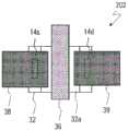
如图6A和图6B所示,PS-TFT202例如是顶栅型的TFT。 PS-TFT202具有:结晶质硅半导体层(例如低温多晶硅层)32,其形 成在基板10上;绝缘层34,其覆盖结晶质硅半导体层32;栅极电极 36,其设于绝缘层34上;源极电极38;以及漏极电极39。绝缘层34 中的位于结晶质硅半导体层32和栅极电极36之间的部分作为 PS-TFT202的栅极绝缘层发挥功能。在本说明书中,有时将绝缘层34 称为“PS-TFT用栅极绝缘层”。As shown in FIGS. 6A and 6B , the PS-
结晶质硅半导体层32具有:沟道区域32c;以及源极区域32s及漏 极区域32d,其分别位于活性区域的两侧。在该例中,结晶质硅半导 体层32中的、隔着PS-TFT用栅极绝缘层34与栅极电极36重叠的部分 成为沟道区域32c。在沟道区域32c与源极区域32s及漏极区域32d之间 也可以具有LDD(Lightly Doped Drain:轻掺杂漏极)区域32a。在 此,LDD区域32a与栅极电极36不重叠,但LDD区域32a的一部分或整 体也可以隔着PS-TFT用栅极绝缘层34与栅极电极36重叠。The crystalline
栅极电极36是使用与OS-TFT201的副栅极电极12s、12d相同的导 电膜(副栅极用导电膜)形成的。在结晶质硅半导体层32和栅极电 极36上,延伸设置有作为OS-TFT201的副栅极绝缘层的第1绝缘层14。 第1绝缘层14是OS-TFT201的副栅极绝缘层的一部分并且是PS-TFT202的层间绝缘层。此外,在此所说的“层间绝缘层”是指在 顶栅型的PS-TFT202中以与栅极电极36接触的方式配置在栅极电极 36与源极电极38及漏极电极39之间的绝缘层。The
源极电极38和漏极电极39使用与OS-TFT201的主栅极电极16相 同的导电膜(主栅极用导电膜)形成于第1绝缘层14上。源极电极38 和漏极电极39分别在形成于第1绝缘层14的接触孔14s、14d内连接到 源极区域32s和漏极区域32d。The
在PS-TFT202上,以覆盖PS-TFT202的方式延伸设置有第2绝缘层 18、保护层26以及上部绝缘层28。On the PS-
此外,在本说明书中,有时将OS-TFT201称为“第1薄膜晶体管”、 将OS-TFT201的源极电极22、漏极电极分别称为“第1源极电极”、“第 1漏极电极”。同样地,有时将PS-TFT202称为“第2薄膜晶体管”,将 PS-TFT202的源极电极38、漏极电极39、栅极电极36分别称为“第2 源极电极”、“第2漏极电极”、“第2栅极电极”。In addition, in this specification, the OS-
在本实施方式中,OS-TFT201的副栅极电极12s、12d和PS-TFT202 的栅极电极36形成于相同的层内。因此,成为OS-TFT201的副栅极绝 缘层的一部分的第1绝缘层14在PS-TFT202中作为层间绝缘层发挥功 能。此外,在本说明书中,“形成于相同的层内”是指使用同一膜(导 电膜)形成。由此,能抑制制造工序数和制造成本的增加。In this embodiment mode, the
与前述的实施方式同样地,以与OS-TFT201的偏置区域30s、30d 对应的方式配置有副栅极电极12s、12d,因此能抑制由偏置结构导致 的导通电流的下降。另外,将副栅极电极12s、12d和PS-TFT202的栅 极电极36形成于相同的层内,由此能简化制造工序。As in the above-described embodiment, the
图7的(a)是表示在同一基板上具备氧化物半导体TFT901和结 晶质硅TFT902的比较例的半导体装置3000的截面图。Fig. 7(a) is a cross-sectional view showing a
比较例的半导体装置3000与图6所示的OS-TFT201的不同之处在 于,氧化物半导体TFT901是具有偏置结构的底栅型的TFT,不具有 副栅极电极。结晶质硅TFT902是具有与图6所示的PS-TFT202同样的 构成的顶栅型的TFT。在图7的(a)中,为了简化,对与图6同样的 构成要素附上相同的附图标记。The
在半导体装置3000中,氧化物半导体TFT901和结晶质硅TFT902 的栅极电极16、36形成于相同的层(栅极配线层)内。另外,氧化 物半导体TFT901和结晶质硅TFT902的源极电极22、38及漏极电极 24、39形成于相同的层(源极配线层)内。此外,这样将结晶质硅 TFT和氧化物半导体TFT的栅极电极形成于相同的层内、将结晶质硅 TFT和氧化物半导体TFT的源极电极/漏极电极形成于相同的层内的 构成例如已在特开2010-3910号公报中公开。In the
在比较例的半导体装置3000中,第2绝缘层18作为氧化物半导体 TFT901的栅极绝缘层(相当于本实施方式的主栅极绝缘层)发挥功 能,并且作为结晶质硅TFT902的层间绝缘层发挥功能。但是,对于 结晶质硅TFT902的层间绝缘层,为了降低栅极/源极间的寄生电容而 要求其厚膜化,而对于氧化物半导体TFT901的栅极绝缘层,为了提 高氧化物半导体TFT901的驱动能力而要求其薄膜化。因而,设定第2 绝缘层18的厚度使得这两种TFT均能具有所希望的特性是困难的。而 且,为了确保氧化物半导体TFT901的可靠性,优选栅极绝缘层使用 含氢率低的绝缘膜,但这与结晶质硅TFT902的层间绝缘层所要求的 性质不同。In the
而在本实施方式的半导体装置1001中,成为PS-TFT202的层间绝 缘层的第1绝缘层14和成为OS-TFT201的主栅极绝缘层的第2绝缘层 18形成于不同的层内。因而,能根据各TFT的用途使PS-TFT202的层 间绝缘层和OS-TFT201的主栅极绝缘层的厚度、材料等条件独立地实 现最佳化。其结果是,能兼顾OS-TFT201和PS-TFT202的可靠性和特 性。On the other hand, in the
作为PS-TFT202的层间绝缘层,也可以使用能供给氢的供氢性的 层。由此,在层间绝缘层形成后进行的加热处理中,能从供氢性的 层对结晶质硅半导体层供给氢,因此能减少在结晶质硅半导体层中 产生的结晶缺陷。层间绝缘层例如可以是主要包含氮化硅的氮化硅 (SiNx)层、氮化氧化硅(SiNxOy:x>y)层、以TEOS(Tetra Ethyl Ortho Silicate:正硅酸乙酯)为原料并用CVD法形成的SiO2膜(TEOS 膜)或它们的层叠膜。PS-TFT202的层间绝缘层所优选的厚度例如是 50nm以上200nm以下。As the interlayer insulating layer of the PS-
另一方面,也可以使用能供给氧的供氧性的层作为OS-TFT201 的主栅极绝缘层。例如可以是主要包含氧化硅的氧化硅(SiOx)层、 氧化氮化硅(SiOxNy:x>y)层等。由此,从供氧性的层向氧化物 半导体层20供给氧,因此能减少在氧化物半导体层20中产生的缺氧。因而,能提高OS-TFT201的可靠性。此外,当使用SiOx层作为供氧性 的层时,能在与氧化物半导体层20的界面形成良好的沟道界面,因 此能进一步提高OS-TFT201的可靠性。OS-TFT201的主栅极绝缘层所 优选的厚度例如是200nm以上500nm以下。On the other hand, an oxygen-supplying layer capable of supplying oxygen may be used as the main gate insulating layer of the OS-
而且,根据本实施方式,还有能缩小图5所示的配线区域910的 面积的优点。Furthermore, according to the present embodiment, there is also an advantage that the area of the
图7的(b)是示意性地表示比较例的半导体装置3000的配线区 域的截面图,图7的(c)是示意性地表示本实施方式的半导体装置 1001的配线区域910的一部分的截面图。图7的(b)和图7的(c)相 当于沿着图5所示的A-A’线的截面。FIG. 7( b ) is a cross-sectional view schematically showing a wiring region of the
在比较例1的半导体装置3000中,作为信号线使用的配线层(金 属层)是栅极配线层和源极配线层这2层。因而,在配线区域910中, 从图7的(b)可知,当从基板10的法线方向观看时,源极配线层内 的配线Ls和栅极配线层内的配线Lg交替地排列(2层配线)。而在本实施方式中,如图7的(c)所示,当从基板10的法线方向观看时, 能使与OS-TFT201的副栅极电极12为相同的层(副栅极配线层)内的 配线Lg1、与OS-TFT201的主栅极电极16为相同的层(主栅极配线层) 内的配线Lg2以及与OS-TFT201的源极电极22为相同的层(源极配线层)内的配线Ls这3层交替地排列(3层配线)。因而,与2层配线相 比,能缩小配线区域910并且还能降低配线间的电容。In the
在本实施方式中,只要OS-TFT201和PS-TFT202形成于同一基板 上即可,各TFT的用途没有特别限定。不过,当将OS-TFT201作为像 素TFT、将PS-TFT202作为驱动TFT使用时,有下面的优点。In the present embodiment, as long as the OS-
OS-TFT201的截止漏电流例如小到多晶硅TFT的(1/1000)。因此, 当使OS-TFT201作为像素TFT发挥功能时,能降低耗电。另外,氧化 物半导体层20能不经由接触孔而与源极电极22和漏极电极24连接。 因而,例如与将结晶质硅TFT作为像素TFT使用的情况相比,能缩小 接触孔部的面积,因此能提高开口率。另一方面,PS-TFT202具有高 迁移率,因此能缩小电路面积。The off-leakage current of the OS-
接着,说明本实施方式的半导体装置1001的制造方法。Next, a method of manufacturing the
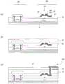
图8的(a)~(d)和图9的(a)~(c)是用于说明半导体装置 1001的制造方法的一例的工序截面图。FIGS. 8(a) to (d) and 9(a) to (c) are process cross-sectional views for explaining an example of a method of manufacturing the
首先,在基板10上形成基底层11。接下来,在驱动电路区域920 中,在基底层11上形成岛状的结晶质硅半导体层(在此为多晶硅层) 32。结晶质硅半导体层32的厚度例如可以是30nm以上70nm以下。First, the
作为基板10,能使用玻璃基板、树脂板或树脂膜等各种基板。 虽然基底层11没有特别限定,但是例如可以形成以氮化硅(SiNx) 膜为下层、以氧化硅(SiOx)膜为上层的层叠膜。结晶质硅半导体 层32例如是通过形成非晶硅(a-Si)膜并使其结晶化、将得到的结晶质硅膜进行图案化而形成的。例如能用等离子体CVD(Chemical Vapor Deposition:化学气相沉积)法或溅射法等公知的方法进行a-Si 膜的形成。例如可以用准分子激光退火法对a-Si膜进行a-Si膜的结晶 化。As the
接着,如图8的(b)所示,以覆盖结晶质硅半导体层32的方式 形成PS-TFT用栅极绝缘层(厚度:例如50nm以上130nm以下)34。 虽然PS-TFT用栅极绝缘层34没有特别限定,但是例如是SiNx膜。在 此,还将PS-TFT用栅极绝缘层34延伸设置到显示区域800。Next, as shown in Fig. 8(b), a gate insulating layer (thickness: for example, 50 nm or more and 130 nm or less) 34 is formed so as to cover the crystalline
接着,在形成副栅极用导电膜后,对其进行图案化。由此,在 驱动电路区域920中,以隔着PS-TFT用栅极绝缘层34与结晶质硅半导 体层32的一部分重叠的方式设置栅极电极36,并且在显示区域800中 设置副栅极电极12s、12d。副栅极用导电膜的材料、厚度等可以与前 述的实施方式相同。在此,例如使用将Ti膜、Al膜和Ti膜按该顺序层 叠而成的层叠膜(Ti/Al/Ti)。Next, after forming the conductive film for the sub-gate, it is patterned. As a result, the
其后,以栅极电极36为掺杂掩模向结晶质硅半导体层32注入杂 质,形成第1杂质注入区域(第1杂质掺杂工序)。接下来,形成未图 示的抗蚀剂掩模,将其作为掺杂掩模使用,对第1杂质注入区域的一 部分进一步注入杂质,形成源极区域32s和漏极区域32d(第2杂质掺 杂工序)。第1杂质注入区域中的未在第2次杂质掺杂工序中注入杂质 的区域成为LDD区域32a。另外,结晶质硅半导体层32中的在2次杂 质掺杂工序中均未注入杂质的区域成为活性区域(沟道区域)32c。 此外,也可以仅进行上述的第1杂质掺杂工序,不形成LDD区域。After that, impurities are implanted into the crystalline
接着,如图8的(c)所示,形成覆盖栅极电极36和副栅极电极12s、 12d的第1绝缘层14。第1绝缘层14的材料和厚度等可以与前述的实施 方式相同。可以形成SiNx膜作为第1绝缘层14。另外,也可以以TEOS (Tetra Ethyl Ortho Silicate:正硅酸乙酯)为原料并用CVD法形成 SiO2膜(TEOS膜)。或者也可以形成SiNx膜和TEOS膜的层叠膜。在 此,使用从栅极电极36侧起将TEOS膜(厚度:例如700m)、SiNx膜 (厚度:例如300nm)和TEOS膜(厚度:例如100nm)按该顺序层 叠而成的层叠膜。第1绝缘层14作为PS-TFT的层间绝缘层发挥功能并且作为OS-TFT的副栅极绝缘层的一部分发挥功能。此外,由于第1 绝缘层14不与OS-TFT的氧化物半导体层接触,因此第1绝缘层14也可 以是含氢率比较高的层。Next, as shown in FIG. 8( c ), the first insulating
接着,在PS-TFT用栅极绝缘层34和第1绝缘层14中形成分别到达 结晶质硅半导体层32的源极区域32s和漏极区域32d的接触孔14s、 14s。Next, contact holes 14s and 14s reaching the
其后,在第1绝缘层14上和接触孔内形成导电膜(主栅极用导电 膜),并对其进行图案化。由此,在驱动电路区域920中,形成在接 触孔14s内与源极区域32s接触的源极电极38、在接触孔14d内与漏极 区域32d接触的漏极电极39,并且在显示区域800中形成栅极电极16。 这样,制造作为驱动TFT的PS-TFT202。After that, a conductive film (conductive film for main gate) is formed on the first insulating
主栅极用导电膜的材料、厚度等可以与前述的实施方式相同。 在此,例如使用将Ti膜、Al膜和Ti膜按该顺序层叠而成的层叠膜 (Ti/Al/Ti)。The material, thickness, and the like of the conductive film for the main gate may be the same as those in the aforementioned embodiment. Here, for example, a laminated film (Ti/Al/Ti) in which a Ti film, an Al film and a Ti film are laminated in this order is used.
接下来,如图8的(d)所示,以覆盖PS-TFT202的源极电极38和 漏极电极39以及OS-TFT的栅极电极16的方式形成第2绝缘层18。第2 绝缘层18作为OS-TFT的主栅极绝缘层发挥功能。第2绝缘层18的形成 方法、材料、厚度等可以与前述的实施方式相同。Next, as shown in Fig. 8(d), the second insulating
接着,如图9的(a)所示,在第2绝缘层18上形成岛状的氧化物 半导体层20后,以与氧化物半导体层20接触的方式形成源极电极22 和漏极电极24。氧化物半导体层20、源极电极22和漏极电极24的形 成方法、材料、厚度等与前述的实施方式相同。这样,制造作为像素TFT的OS-TFT201。Next, as shown in FIG. 9( a ), after the island-shaped
接下来,如图9的(b)所示,形成覆盖PE-TFT202和OS-TFT201 的保护层26和上部绝缘层28。它们的形成方法、材料、厚度等与前 述的实施方式相同。Next, as shown in (b) of FIG. 9 , the
接着,如图9的(c)所示,在上部绝缘层28上形成共用电极40。 共用电极40可使用ITO(铟锡氧化物)膜、IZO膜或ZnO膜(氧化锌 膜)等透明导电膜来形成。共用电极40例如除了位于OS-TFT201上的 区域以外,可以在显示区域800的大致整体上形成。Next, as shown in FIG. 9( c ), the
接下来,在上部绝缘层28上以覆盖共用电极40的方式形成电介 质层42。作为电介质层42,例如能适当地使用氧化硅(SiOx)膜、 氮化硅(SiNx)膜、氧化氮化硅(SiOxNy;x>y)膜、氮化氧化硅 (SiNxOy;x>y)膜等。Next, the
其后,通过光刻,在电介质层42、保护层26和上部绝缘层28中 形成将OS-TFT201的漏极电极24露出的开口(像素接触孔)。接着, 在上部绝缘层28上和像素接触孔内,形成在像素接触孔内与漏极电 极24接触的像素电极44。像素电极44能使用ITO膜、IZO膜、ZnO膜等透明导电膜来形成。虽未图示,但通过在像素电极44设置狭缝状 的开口等对像素电极44的平面图案的变更,能使显示装置支持FFS模 式或IPS模式。这样,能得到本实施方式的半导体装置1001。Thereafter, by photolithography, an opening (pixel contact hole) exposing the
也可以是,像素电极44的至少一部分以隔着电介质层42与共用 电极40重叠的方式配置。由此,在像素电极44和共用电极40隔着电 介质层42重叠的部分形成电容。该电容作为辅助电容发挥功能。通 过适当地调整成为辅助电容的电介质层的电介质层42的材料和厚 度、形成电容的部分的面积等,能得到具有所希望的电容的辅助电 容。因此,无需在像素内例如使用与源极配线相同的金属膜等另外 形成辅助电容。因而,能抑制由于使用金属膜形成辅助电容所致的 开口率的下降。At least a part of the
此外,也可以不设置共用电极40和电介质层42,而在上部绝缘 层28上形成像素电极44。这种半导体装置还能应用于VA模式的显示 装置。Alternatively, the
本实施方式的半导体装置1001还可以具备不具有偏置结构的其 它OS-TFT。其它OS-TFT除了不具有偏置结构且不具有副栅极电极以 外,可以具有与OS-TFT201相同的构成。The
图10的(a)和(b)是例示不具有偏置结构的OS-TFT203的截面 图和俯视图。为了简化,对与OS-TFT201相同的构成要素附上相同的 附图标记。OS-TFT203例如是像素TFT,OS-TFT201和PE-TFT202例 如是电路TFT。(a) and (b) of Fig. 10 are a cross-sectional view and a plan view illustrating the OS-
如图10所示,栅极电极16以隔着第2绝缘层18与氧化物半导体层 20的沟道形成区域整体重叠的方式配置。在OS-TFT203和基板10之间 配置有使用与PS-TFT202的栅极电极36相同的导电膜形成的遮光层 46。由此,与使OS-TFT203的栅极电极16作为遮光层发挥功能的情况 相比,更能减小栅极电极16的沟道长度方向的宽度。因而,能抑制 背光源光对氧化物半导体层20的影响,并能降低在源极电极22及漏 极电极24与遮光层之间产生的寄生电容。在该例中,氧化物半导体 层20的源极侧的端部(源极接触区域)的至少一部分和漏极侧的端 部(漏极接触区域)的至少一部分未被栅极电极16遮光而被遮光层 46遮光。此外,遮光层46只要以覆盖氧化物半导体层20中的未被栅 极电极16遮光的区域的方式配置即可,也可以不覆盖氧化物半导体 层20整体。As shown in FIG. 10 , the
(第3实施方式)(third embodiment)
以下,以显示装置的有源矩阵基板为例说明本发明的半导体装 置的第3实施方式。Hereinafter, a third embodiment of the semiconductor device of the present invention will be described by taking an active matrix substrate of a display device as an example.
图11是表示本实施方式的半导体装置1002的OS-TFT301和 PS-TT302的截面图。11 is a cross-sectional view showing an OS-
在前述的实施方式中,将PS-TFT202的源极电极38及漏极电极39 形成在与OS-TFT201的主栅极电极16相同的层(主栅极配线层)内, 但在本实施方式中,将其形成在与OS-TFT301的源极电极22及漏极电 极24相同的层(源极配线层)内。其它构成与参照图6在前面描述过 的半导体装置1001相同。对与图6相同的构成要素附上相同的附图标 记,省略说明。In the aforementioned embodiment, the
在本实施方式中,与第2实施方式同样地,成为PS-TFT302的层 间绝缘层的第1绝缘层14和成为OS-TFT301的主栅极绝缘层的第2绝 缘层18也形成于不同的层,因此能将这些层的材料、厚度等独立地 实现最佳化。因而,能实现高可靠性和良好的TFT特性。In the present embodiment, similarly to the second embodiment, the first insulating
半导体装置1002可用与参照图8和图9在前面描述过的半导体装 置1001的制造方法同样的方法形成。使用图12的(a)~(c)说明半 导体装置1002的制造方法。在以下的说明中,省略与半导体装置1001 同样的工序。另外,半导体装置1002的各构成要素的形成方法、材 料、厚度等也与半导体装置1001相同,因此省略说明。The
首先,用与前述的实施方式同样的方法在基板10上形成基底层 11、结晶质硅半导体层32、绝缘层34、栅极电极16、副栅极电极12s、 12d以及第1绝缘层14。First, the
接下来,如图12的(a)所示,在显示区域800中,在第1绝缘层 14上形成栅极电极16。Next, as shown in Fig. 12(a), in the
接着,如图12的(b)所示,以覆盖第1绝缘层14和栅极电极16 的方式形成第2绝缘层18。其后,在显示区域800中,形成氧化物半 导体层20。在驱动电路区域920中,形成分别到达结晶质硅半导体层 32的源极区域32s和漏极区域32d的接触孔18s、18d。Next, as shown in FIG. 12( b ), the second insulating
其后,如图12的(c)所示,形成源极用导电膜,并对其进行图 案化,从而形成与氧化物半导体层20接触的源极电极22和漏极电极 24,并且形成在接触孔18s、18d内与结晶质硅半导体层32接触的源极 电极38和漏极电极39。接着,虽未图示,但形成保护层26、上部绝缘层28、共用电极40、电介质层42和像素电极44,得到半导体装置 1002。Thereafter, as shown in (c) of FIG. 12 , a source electrode conductive film is formed and patterned to form a
本发明的半导体装置的实施方式不限于上述的第1至第3实施方 式。Embodiments of the semiconductor device of the present invention are not limited to the above-described first to third embodiments.
例如在上述的实施方式中,PS-TFT202、302均具有LDD结构, 但也可以具有LDD区域与栅极电极重叠的GOLD(Gate-Overlapped LDD:栅极重叠轻掺杂漏极)结构。或者也可以不具有LDD区域(单 漏极结构)。还可以根据需要对结晶质硅半导体层32进行用于进行阈值电压控制的沟道掺杂。For example, in the above-mentioned embodiments, the PS-
上述实施方式的OS-TFT和PS-TFT的用途或形成的区域不限于 上述的用途或区域。在具备多个TFT的装置中,只要根据各TFT所要 求的特性分别使用活性层不同的2种TFT即可。例如OS-TFT201、301 不仅作为像素TFT使用,也可以作为构成驱动电路的电路元件使用。The application or the formed area of the OS-TFT and PS-TFT of the above-mentioned embodiment is not limited to the above-mentioned application or area. In a device including a plurality of TFTs, two types of TFTs having different active layers may be used according to the characteristics required for each TFT. For example, the OS-
工业上的可利用性industrial availability
本发明的实施方式能广泛应用于具备多个薄膜晶体管的装置或 电子设备。例如能应用于有源矩阵基板等电路基板、液晶显示装置、 有机电致发光(EL)显示装置和无机电致发光显示装置等显示装置、 放射线检测器、图像传感器等摄像装置、图像输入装置或指纹读取 装置等电子装置等。Embodiments of the present invention can be widely applied to devices or electronic equipment including a plurality of thin film transistors. For example, it can be applied to circuit substrates such as active matrix substrates, liquid crystal display devices, display devices such as organic electroluminescence (EL) display devices, and inorganic electroluminescence display devices, imaging devices such as radiation detectors, image sensors, image input devices, or the like. Electronic devices such as fingerprint reading devices, etc.
附图标记说明Description of reference numerals
10 基板10 Substrates
11 基底层11 basal layer
12、12s、12d 副栅极电极12, 12s, 12d sub-gate electrodes
14 第1绝缘层14 1st insulating layer
16 主栅极电极16 Main gate electrode
18 第2绝缘层18 2nd insulating layer
20 氧化物半导体层20 Oxide semiconductor layer
20g 栅极相对区域20g gate opposite area
20s 源极接触区域20s source contact area
20d 漏极接触区域20d drain contact area
20c 沟道形成区域20c Channel formation region
22 源极电极22 Source electrode
24 漏极电极24 Drain electrode
26 保护层26 protective layer
28 上部绝缘层28 Upper insulating layer
30、30s、30d 偏置区域30, 30s, 30d offset area
32 结晶质硅半导体层32 Crystalline silicon semiconductor layer
34 第3绝缘层34 3rd insulating layer
36 结晶质硅TFT的栅极电极36 Gate electrode of crystalline silicon TFT
38 结晶质硅TFT的源极电极38 Source electrode of crystalline silicon TFT
39 结晶质硅TFT的漏极电极39 Drain electrode of crystalline silicon TFT
40 共用电极40 Common electrode
42 电介质层42 Dielectric layer
44 像素电极44 pixel electrodes
101、201、301 氧化物半导体TFT101, 201, 301 oxide semiconductor TFT
202、302 结晶质硅TFT202, 302 Crystalline silicon TFT
1001、1002 半导体装置。1001, 1002 Semiconductor devices.
Claims (18)
Translated fromChineseApplications Claiming Priority (3)
| Application Number | Priority Date | Filing Date | Title |
|---|---|---|---|
| JP2015202707 | 2015-10-14 | ||
| JP2015-202707 | 2015-10-14 | ||
| PCT/JP2016/080332WO2017065199A1 (en) | 2015-10-14 | 2016-10-13 | Semiconductor device and method for manufacturing same |
Publications (2)
| Publication Number | Publication Date |
|---|---|
| CN108140675A CN108140675A (en) | 2018-06-08 |
| CN108140675Btrue CN108140675B (en) | 2020-12-25 |
Family
ID=58517225
Family Applications (1)
| Application Number | Title | Priority Date | Filing Date |
|---|---|---|---|
| CN201680059777.2AExpired - Fee RelatedCN108140675B (en) | 2015-10-14 | 2016-10-13 | Semiconductor device and method for manufacturing the same |
Country Status (3)
| Country | Link |
|---|---|
| US (1) | US10297694B2 (en) |
| CN (1) | CN108140675B (en) |
| WO (1) | WO2017065199A1 (en) |
Families Citing this family (18)
| Publication number | Priority date | Publication date | Assignee | Title |
|---|---|---|---|---|
| KR102324219B1 (en)* | 2017-04-24 | 2021-11-12 | 삼성디스플레이 주식회사 | Display device and manufacturing method of the same |
| KR101894029B1 (en)* | 2017-07-21 | 2018-10-04 | 울산과학기술원 | Finger print and pressure dual sensor and method of manufacturing the same |
| JP6960807B2 (en) | 2017-08-31 | 2021-11-05 | 株式会社ジャパンディスプレイ | Display device and its manufacturing method |
| CN108376695B (en)* | 2018-02-05 | 2021-01-08 | 惠科股份有限公司 | A display panel and display device |
| WO2019186798A1 (en)* | 2018-03-28 | 2019-10-03 | シャープ株式会社 | Display device and production method for display device |
| US10818697B2 (en)* | 2018-08-06 | 2020-10-27 | Sharp Kabushiki Kaisha | Semiconductor device, display device, and method of producing semiconductor device |
| CN110212035B (en)* | 2018-08-10 | 2023-12-19 | 友达光电股份有限公司 | Transistor structure and method of operation |
| TWI683171B (en)* | 2018-12-05 | 2020-01-21 | 友達光電股份有限公司 | Thin film transistor |
| JP7327940B2 (en)* | 2019-01-10 | 2023-08-16 | 株式会社ジャパンディスプレイ | Semiconductor device and display device |
| CN109888019B (en)* | 2019-01-29 | 2021-04-02 | 中山大学 | Heterostructure oxide thin film transistor based on quasi-modulation doping effect |
| CN112635571B (en)* | 2019-09-24 | 2024-08-02 | 乐金显示有限公司 | Thin film transistor, method for manufacturing the same, and display device including the same |
| CN111179742A (en)* | 2020-02-12 | 2020-05-19 | 武汉华星光电技术有限公司 | A display panel, gate drive circuit and electronic device |
| US11581340B2 (en)* | 2020-12-15 | 2023-02-14 | Sharp Kabushiki Kaisha | Active matrix substrate |
| CN115472635B (en)* | 2021-06-11 | 2025-04-22 | 和鑫光电股份有限公司 | Light sensing device with biased gate electrode and light sensing panel using the same |
| CN115768195A (en)* | 2021-09-03 | 2023-03-07 | 乐金显示有限公司 | Thin film transistor substrate and display device including the same |
| TWI798830B (en)* | 2021-09-13 | 2023-04-11 | 友達光電股份有限公司 | Thin film transistor |
| CN115050763A (en)* | 2022-08-02 | 2022-09-13 | 福建华佳彩有限公司 | TFT array substrate for reducing parasitic capacitance and manufacturing method thereof |
| CN115568250A (en)* | 2022-08-30 | 2023-01-03 | 惠科股份有限公司 | In-screen fingerprint display screen, manufacturing method thereof and display device |
Citations (2)
| Publication number | Priority date | Publication date | Assignee | Title |
|---|---|---|---|---|
| US6534788B1 (en)* | 1998-07-30 | 2003-03-18 | Lg Philips Lcd Co., Ltd | Thin film transistor having dual gate structure and a fabricating method thereof |
| CN104218091A (en)* | 2013-05-31 | 2014-12-17 | 三星显示有限公司 | Thin film transistor and organic light emitting diode display including the same |
Family Cites Families (15)
| Publication number | Priority date | Publication date | Assignee | Title |
|---|---|---|---|---|
| JPH0590587A (en)* | 1991-09-30 | 1993-04-09 | Sony Corp | Insulation gate type field effect transistor |
| TW480732B (en)* | 2001-04-10 | 2002-03-21 | Ind Tech Res Inst | Polysilicon thin film transistor having gate-overlapped lightly doped drain |
| JP4673513B2 (en)* | 2001-08-01 | 2011-04-20 | 株式会社半導体エネルギー研究所 | Method for manufacturing semiconductor device |
| JP4454921B2 (en)* | 2002-09-27 | 2010-04-21 | 株式会社半導体エネルギー研究所 | Method for manufacturing semiconductor device |
| JP2010003910A (en) | 2008-06-20 | 2010-01-07 | Toshiba Mobile Display Co Ltd | Display element |
| KR101056229B1 (en) | 2009-10-12 | 2011-08-11 | 삼성모바일디스플레이주식회사 | An organic light emitting display device comprising a thin film transistor, a method of manufacturing the same, and a thin film transistor |
| CN103500712B (en) | 2010-12-03 | 2016-05-25 | 株式会社半导体能源研究所 | Semiconductor device |
| US8952377B2 (en) | 2011-07-08 | 2015-02-10 | Semiconductor Energy Laboratory Co., Ltd. | Semiconductor device and manufacturing method thereof |
| CN104380473B (en) | 2012-05-31 | 2017-10-13 | 株式会社半导体能源研究所 | Semiconductor device |
| KR20140009023A (en) | 2012-07-13 | 2014-01-22 | 가부시키가이샤 한도오따이 에네루기 켄큐쇼 | Semiconductor device |
| WO2014157019A1 (en) | 2013-03-25 | 2014-10-02 | Semiconductor Energy Laboratory Co., Ltd. | Semiconductor device |
| JP6246518B2 (en)* | 2013-07-29 | 2017-12-13 | 株式会社半導体エネルギー研究所 | Transistor |
| KR20150086969A (en)* | 2014-01-21 | 2015-07-29 | 삼성디스플레이 주식회사 | Liquid crystal display and method for manufacturing the same |
| US9881986B2 (en)* | 2014-02-24 | 2018-01-30 | Lg Display Co., Ltd. | Thin film transistor substrate and display using the same |
| US10186528B2 (en)* | 2014-02-24 | 2019-01-22 | Lg Display Co., Ltd. | Thin film transistor substrate and display using the same |
- 2016
- 2016-10-13USUS15/767,699patent/US10297694B2/enactiveActive
- 2016-10-13WOPCT/JP2016/080332patent/WO2017065199A1/ennot_activeCeased
- 2016-10-13CNCN201680059777.2Apatent/CN108140675B/ennot_activeExpired - Fee Related
Patent Citations (2)
| Publication number | Priority date | Publication date | Assignee | Title |
|---|---|---|---|---|
| US6534788B1 (en)* | 1998-07-30 | 2003-03-18 | Lg Philips Lcd Co., Ltd | Thin film transistor having dual gate structure and a fabricating method thereof |
| CN104218091A (en)* | 2013-05-31 | 2014-12-17 | 三星显示有限公司 | Thin film transistor and organic light emitting diode display including the same |
Also Published As
| Publication number | Publication date |
|---|---|
| US10297694B2 (en) | 2019-05-21 |
| WO2017065199A1 (en) | 2017-04-20 |
| CN108140675A (en) | 2018-06-08 |
| US20180301566A1 (en) | 2018-10-18 |
Similar Documents
| Publication | Publication Date | Title |
|---|---|---|
| CN108140675B (en) | Semiconductor device and method for manufacturing the same | |
| JP6101357B2 (en) | Semiconductor device and manufacturing method thereof | |
| CN110521003B (en) | Active matrix substrate and manufacturing method thereof | |
| CN104205341B (en) | Semiconductor device and its manufacture method | |
| US20120199891A1 (en) | Semiconductor device and method for manufacturing same | |
| US9214533B2 (en) | Semiconductor device having transparent electrodes | |
| JP2020047920A (en) | Active matrix substrate and manufacturing method thereof | |
| CN106415801B (en) | Semiconductor device and manufacturing method thereof | |
| CN104685635A (en) | Semiconductor device | |
| US10985281B2 (en) | Transistor, thin film transistor array panel, and related manufacturing method | |
| US11791345B2 (en) | Active matrix substrate and method for manufacturing same | |
| CN104285286A (en) | Semiconductor device and manufacturing method thereof | |
| JP7471075B2 (en) | Active matrix substrate and its manufacturing method | |
| US20210013238A1 (en) | Active matrix substrate and method for manufacturing same | |
| US11721704B2 (en) | Active matrix substrate | |
| US9276126B2 (en) | Semiconductor device and method for producing same | |
| CN104040724B (en) | Semiconductor device, display device, and method for manufacturing semiconductor device | |
| JP2024097937A (en) | Active matrix substrate, liquid crystal display device, and method for manufacturing active matrix substrate | |
| JP2022191755A (en) | Semiconductor device | |
| US8686528B2 (en) | Semiconductor device | |
| JP2023153641A (en) | Active matrix substrate and manufacturing method thereof | |
| CN115734672A (en) | Active matrix substrate and method for manufacturing the same |
Legal Events
| Date | Code | Title | Description |
|---|---|---|---|
| PB01 | Publication | ||
| PB01 | Publication | ||
| SE01 | Entry into force of request for substantive examination | ||
| SE01 | Entry into force of request for substantive examination | ||
| GR01 | Patent grant | ||
| GR01 | Patent grant | ||
| CF01 | Termination of patent right due to non-payment of annual fee | ||
| CF01 | Termination of patent right due to non-payment of annual fee | Granted publication date:20201225 |