CN108140265B - System and method for anatomical shell editing - Google Patents
System and method for anatomical shell editingDownload PDFInfo
- Publication number
- CN108140265B CN108140265BCN201680056008.7ACN201680056008ACN108140265BCN 108140265 BCN108140265 BCN 108140265BCN 201680056008 ACN201680056008 ACN 201680056008ACN 108140265 BCN108140265 BCN 108140265B
- Authority
- CN
- China
- Prior art keywords
- anatomical shell
- anatomical
- test
- point
- test point
- Prior art date
- Legal status (The legal status is an assumption and is not a legal conclusion. Google has not performed a legal analysis and makes no representation as to the accuracy of the status listed.)
- Active
Links
Images


Classifications
- G—PHYSICS
- G06—COMPUTING OR CALCULATING; COUNTING
- G06T—IMAGE DATA PROCESSING OR GENERATION, IN GENERAL
- G06T19/00—Manipulating 3D models or images for computer graphics
- G06T19/20—Editing of 3D images, e.g. changing shapes or colours, aligning objects or positioning parts
- G—PHYSICS
- G06—COMPUTING OR CALCULATING; COUNTING
- G06T—IMAGE DATA PROCESSING OR GENERATION, IN GENERAL
- G06T15/00—3D [Three Dimensional] image rendering
- G06T15/04—Texture mapping
- G—PHYSICS
- G06—COMPUTING OR CALCULATING; COUNTING
- G06T—IMAGE DATA PROCESSING OR GENERATION, IN GENERAL
- G06T17/00—Three dimensional [3D] modelling, e.g. data description of 3D objects
- G06T17/20—Finite element generation, e.g. wire-frame surface description, tesselation
- G—PHYSICS
- G16—INFORMATION AND COMMUNICATION TECHNOLOGY [ICT] SPECIALLY ADAPTED FOR SPECIFIC APPLICATION FIELDS
- G16H—HEALTHCARE INFORMATICS, i.e. INFORMATION AND COMMUNICATION TECHNOLOGY [ICT] SPECIALLY ADAPTED FOR THE HANDLING OR PROCESSING OF MEDICAL OR HEALTHCARE DATA
- G16H50/00—ICT specially adapted for medical diagnosis, medical simulation or medical data mining; ICT specially adapted for detecting, monitoring or modelling epidemics or pandemics
- G16H50/50—ICT specially adapted for medical diagnosis, medical simulation or medical data mining; ICT specially adapted for detecting, monitoring or modelling epidemics or pandemics for simulation or modelling of medical disorders
- A—HUMAN NECESSITIES
- A61—MEDICAL OR VETERINARY SCIENCE; HYGIENE
- A61B—DIAGNOSIS; SURGERY; IDENTIFICATION
- A61B2576/00—Medical imaging apparatus involving image processing or analysis
- A61B2576/02—Medical imaging apparatus involving image processing or analysis specially adapted for a particular organ or body part
- A61B2576/023—Medical imaging apparatus involving image processing or analysis specially adapted for a particular organ or body part for the heart
- A—HUMAN NECESSITIES
- A61—MEDICAL OR VETERINARY SCIENCE; HYGIENE
- A61B—DIAGNOSIS; SURGERY; IDENTIFICATION
- A61B5/00—Measuring for diagnostic purposes; Identification of persons
- A61B5/24—Detecting, measuring or recording bioelectric or biomagnetic signals of the body or parts thereof
- A61B5/25—Bioelectric electrodes therefor
- A—HUMAN NECESSITIES
- A61—MEDICAL OR VETERINARY SCIENCE; HYGIENE
- A61B—DIAGNOSIS; SURGERY; IDENTIFICATION
- A61B5/00—Measuring for diagnostic purposes; Identification of persons
- A61B5/24—Detecting, measuring or recording bioelectric or biomagnetic signals of the body or parts thereof
- A61B5/316—Modalities, i.e. specific diagnostic methods
- A61B5/318—Heart-related electrical modalities, e.g. electrocardiography [ECG]
- A61B5/339—Displays specially adapted therefor
- A—HUMAN NECESSITIES
- A61—MEDICAL OR VETERINARY SCIENCE; HYGIENE
- A61B—DIAGNOSIS; SURGERY; IDENTIFICATION
- A61B5/00—Measuring for diagnostic purposes; Identification of persons
- A61B5/68—Arrangements of detecting, measuring or recording means, e.g. sensors, in relation to patient
- A61B5/6846—Arrangements of detecting, measuring or recording means, e.g. sensors, in relation to patient specially adapted to be brought in contact with an internal body part, i.e. invasive
- A61B5/6847—Arrangements of detecting, measuring or recording means, e.g. sensors, in relation to patient specially adapted to be brought in contact with an internal body part, i.e. invasive mounted on an invasive device
- A61B5/6852—Catheters
- A61B5/6858—Catheters with a distal basket, e.g. expandable basket
- A—HUMAN NECESSITIES
- A61—MEDICAL OR VETERINARY SCIENCE; HYGIENE
- A61B—DIAGNOSIS; SURGERY; IDENTIFICATION
- A61B5/00—Measuring for diagnostic purposes; Identification of persons
- A61B5/68—Arrangements of detecting, measuring or recording means, e.g. sensors, in relation to patient
- A61B5/6846—Arrangements of detecting, measuring or recording means, e.g. sensors, in relation to patient specially adapted to be brought in contact with an internal body part, i.e. invasive
- A61B5/6867—Arrangements of detecting, measuring or recording means, e.g. sensors, in relation to patient specially adapted to be brought in contact with an internal body part, i.e. invasive specially adapted to be attached or implanted in a specific body part
- A61B5/6869—Heart
- G—PHYSICS
- G06—COMPUTING OR CALCULATING; COUNTING
- G06F—ELECTRIC DIGITAL DATA PROCESSING
- G06F3/00—Input arrangements for transferring data to be processed into a form capable of being handled by the computer; Output arrangements for transferring data from processing unit to output unit, e.g. interface arrangements
- G06F3/01—Input arrangements or combined input and output arrangements for interaction between user and computer
- G06F3/048—Interaction techniques based on graphical user interfaces [GUI]
- G06F3/0481—Interaction techniques based on graphical user interfaces [GUI] based on specific properties of the displayed interaction object or a metaphor-based environment, e.g. interaction with desktop elements like windows or icons, or assisted by a cursor's changing behaviour or appearance
- G06F3/0482—Interaction with lists of selectable items, e.g. menus
- G—PHYSICS
- G06—COMPUTING OR CALCULATING; COUNTING
- G06T—IMAGE DATA PROCESSING OR GENERATION, IN GENERAL
- G06T2207/00—Indexing scheme for image analysis or image enhancement
- G06T2207/30—Subject of image; Context of image processing
- G06T2207/30004—Biomedical image processing
- G06T2207/30048—Heart; Cardiac
- G—PHYSICS
- G06—COMPUTING OR CALCULATING; COUNTING
- G06T—IMAGE DATA PROCESSING OR GENERATION, IN GENERAL
- G06T2210/00—Indexing scheme for image generation or computer graphics
- G06T2210/41—Medical
- G—PHYSICS
- G06—COMPUTING OR CALCULATING; COUNTING
- G06T—IMAGE DATA PROCESSING OR GENERATION, IN GENERAL
- G06T2219/00—Indexing scheme for manipulating 3D models or images for computer graphics
- G06T2219/20—Indexing scheme for editing of 3D models
- G06T2219/2021—Shape modification
- G—PHYSICS
- G16—INFORMATION AND COMMUNICATION TECHNOLOGY [ICT] SPECIALLY ADAPTED FOR SPECIFIC APPLICATION FIELDS
- G16H—HEALTHCARE INFORMATICS, i.e. INFORMATION AND COMMUNICATION TECHNOLOGY [ICT] SPECIALLY ADAPTED FOR THE HANDLING OR PROCESSING OF MEDICAL OR HEALTHCARE DATA
- G16H30/00—ICT specially adapted for the handling or processing of medical images
- G16H30/40—ICT specially adapted for the handling or processing of medical images for processing medical images, e.g. editing
Landscapes
- Engineering & Computer Science (AREA)
- Physics & Mathematics (AREA)
- Computer Graphics (AREA)
- General Physics & Mathematics (AREA)
- Theoretical Computer Science (AREA)
- Health & Medical Sciences (AREA)
- Public Health (AREA)
- Medical Informatics (AREA)
- Software Systems (AREA)
- Pathology (AREA)
- Architecture (AREA)
- Biomedical Technology (AREA)
- General Health & Medical Sciences (AREA)
- General Engineering & Computer Science (AREA)
- Computer Hardware Design (AREA)
- Primary Health Care (AREA)
- Epidemiology (AREA)
- Databases & Information Systems (AREA)
- Data Mining & Analysis (AREA)
- Geometry (AREA)
- Measurement And Recording Of Electrical Phenomena And Electrical Characteristics Of The Living Body (AREA)
- Life Sciences & Earth Sciences (AREA)
- Surgical Instruments (AREA)
- Biophysics (AREA)
- Heart & Thoracic Surgery (AREA)
- Molecular Biology (AREA)
- Surgery (AREA)
- Animal Behavior & Ethology (AREA)
- Veterinary Medicine (AREA)
Abstract
Description
Translated fromChinese相关申请的交叉引用CROSS-REFERENCE TO RELATED APPLICATIONS
本申请要求于2015年9月26日提交的临时申请No.62/233,347的优先权,其通过引用整体并入本文。This application claims priority to Provisional Application No. 62/233,347, filed September 26, 2015, which is incorporated herein by reference in its entirety.
技术领域technical field
本公开总体上涉及心脏映射系统和方法。更具体地,本公开涉及编辑基于心脏结构的解剖外壳(anatomical shell)。The present disclosure generally relates to cardiac mapping systems and methods. More specifically, the present disclosure relates to editing anatomical shells based on cardiac structures.
背景技术Background technique
诊断和治疗心脏疾病通常涉及将导管通过周围脉管系统引入心室中。该导管具有位于导管远端的多个传感器。从多个传感器接收到的信息(包括多个传感器的位置和与每个位置相关联的电信号)可以被用于生成和显示心室的近似解剖外壳。在一些情况下,解剖外壳可以包括与每个位置相关联的电信号的特征的表示。解剖外壳可以由医生或其他医学专业人员使用以用于治疗心脏疾病。Diagnosing and treating heart disease often involves introducing a catheter through the surrounding vasculature into the ventricle. The catheter has a plurality of sensors located at the distal end of the catheter. Information received from the plurality of sensors, including the positions of the plurality of sensors and the electrical signals associated with each position, can be used to generate and display an approximate anatomical enclosure of the ventricle. In some cases, the anatomical enclosure may include representations of characteristics of the electrical signals associated with each location. Anatomical shells may be used by physicians or other medical professionals for the treatment of heart disease.
解剖外壳构造的一个考虑是解剖外壳的形状与心脏组织的实际形状有多接近。尽管使用具有多个传感器的导管的解剖外壳构造可以提供心脏组织的合理近似,但是常常可能存在与其相关联的各种问题。一个问题是“接触不足(under-contact)”,其中构造的解剖外壳的一些点与实际组织有很大距离。另一个问题是“过度接触(over-contact)”,其中导管操作员在重构阶段的一部分期间施加了太大的力并向外推动心脏组织,导致构成心室的夸大表示的形状。甚至另一个问题是“网状(webbing)”,其中心室的小而尖锐的特征没有出现在解剖外壳上。这个问题可能由导管的刚性而加剧。One consideration in the construction of the anatomical shell is how closely the shape of the anatomical shell approximates the actual shape of the heart tissue. Although an anatomical housing configuration using a catheter with multiple sensors may provide a reasonable approximation of cardiac tissue, there may often be various problems associated therewith. One problem is "under-contact", where some points of the constructed anatomical shell are a great distance from the actual tissue. Another problem is "over-contact," where the catheter operator applies too much force and pushes the heart tissue outward during part of the remodeling phase, resulting in shapes that make up an exaggerated representation of the ventricle. Even another problem is "webbing", the small, sharp features of the central chamber that do not appear on the anatomical shell. This problem may be exacerbated by the rigidity of the catheter.
发明内容SUMMARY OF THE INVENTION
本文公开的主题的实施例包括促进编辑所构造的解剖外壳的心脏映射系统(cardiac mapping system)。在实施例中,用户编辑工具箱可以包括用于选择和移除特定子体积和/或表面区域等的工具。在实施例中,处理装置可以被配置为实现一个或多个算法以自动编辑解剖外壳。以这种方式,本公开的实施例可以促进增强心脏映射技术的准确性。示例性实施例包括以下内容。Embodiments of the subject matter disclosed herein include a cardiac mapping system that facilitates editing of constructed anatomical shells. In an embodiment, the user editing toolbox may include tools for selecting and removing specific sub-volumes and/or surface areas and the like. In an embodiment, the processing device may be configured to implement one or more algorithms to automatically edit the anatomical shell. In this manner, embodiments of the present disclosure may facilitate enhancing the accuracy of cardiac mapping techniques. Exemplary embodiments include the following.
在示例1中,一种用于电压引导的解剖外壳编辑的处理器实现的方法,基于处理器的方法包括:向显示装置输出心脏结构的解剖外壳,其中所述解剖外壳基于由映射探针感测到的多个信号,并且其中所述多个信号中的每个包括相应的感测到的电压;从用户输入装置接收指定用于编辑的第一目标深度的用户输入;从用户输入装置接收对所述解剖外壳的第一区域的选择;通过以下方式生成第一修改的解剖外壳:移除所述解剖外壳的第一部分,所述解剖外壳的第一部分包括表面的所选第一区域并且基于所述第一目标深度向内延伸到第一编辑深度,所述第一编辑深度包括至少一个有限深度,并且在所述第一修改的解剖外壳上生成第一新表面区域,其对应于所选区域,其中所述第一新表面被布置在所述第一编辑深度处并且包括在所述第一编辑深度处的感测到的电压的至少一个表示;并且向所述显示装置输出所述第一修改的解剖外壳。In Example 1, a processor-implemented method for voltage-guided anatomical shell editing, the processor-based method comprising: outputting an anatomical shell of a cardiac structure to a display device, wherein the anatomical shell is based on sensing by a mapping probe a plurality of signals detected, and wherein each of the plurality of signals includes a corresponding sensed voltage; receiving a user input from a user input device specifying a first target depth for editing; receiving from a user input device selection of a first region of the anatomical shell; generating a first modified anatomical shell by removing a first portion of the anatomical shell comprising the selected first region of the surface and based on The first target depth extends inwardly to a first edit depth, the first edit depth includes at least one finite depth, and a first new surface area is generated on the first modified anatomical shell that corresponds to the selected an area, wherein the first new surface is disposed at the first edit depth and includes at least one representation of the sensed voltage at the first edit depth; and outputting the first edit depth to the display device A modified anatomical shell.
在示例2中,根据示例1所述的方法,还包括:从所述用户输入装置接收命令以撤销所述第一修改的解剖外壳的生成;再生所述解剖外壳;并且将再生的解剖外壳输出到所述显示装置。In example 2, the method of example 1, further comprising: receiving a command from the user input device to undo generation of the first modified anatomical shell; regenerating the anatomical shell; and outputting the regenerated anatomical shell to the display device.
在示例3中,根据示例1和2中任一项所述的方法,还包括:从用户输入装置接收指定用于编辑的第二目标深度的用户输入;从用户输入装置接收对所述解剖外壳的第二区域的选择,所述第二区域包括所述第一区域的至少一部分;通过以下方式生成第二修改的解剖外壳:移除所述解剖外壳的第二部分,所述解剖外壳的第二部分包括所述表面的所选第二区域,并且基于所述第二目标深度向内延伸到第二编辑深度,所述第二编辑深度包括至少一个有限深度,并且在所述第二修改的解剖外壳上生成第二新表面区域,其对应于所述所选第二区域,其中所述第二新表面被布置在所述第二编辑深度处并且包括在所述第二编辑深度处的感测到的电压的至少一个表示;并且向所述显示装置输出所述第二修改的解剖外壳。In example 3, the method of any one of examples 1 and 2, further comprising: receiving user input from a user input device specifying a second target depth for editing; receiving from a user input device a response to the anatomical shell selection of a second region of the The second portion includes a selected second region of the surface and extends inwardly to a second edit depth based on the second target depth, the second edit depth including at least one finite depth, and at the second modified A second new surface area is generated on the anatomical shell, which corresponds to the selected second area, wherein the second new surface is arranged at the second edit depth and includes the senses at the second edit depth. at least one representation of the measured voltage; and outputting the second modified anatomical enclosure to the display device.
在示例4中,根据示例3所述的方法,其中,所述第二目标深度为至少1毫米且至多5毫米。In example 4, the method of example 3, wherein the second target depth is at least 1 millimeter and at most 5 millimeters.
在示例5中,根据示例3至4中任一项所述的方法,其中,所述第一编辑深度处的感测到的电压的至少一个表示指示对应于血池的电压幅值。In Example 5, the method of any one of Examples 3-4, wherein at least one representation of the sensed voltage at the first edit depth is indicative of a voltage magnitude corresponding to a blood pool.
在示例6中,根据示例3至5中任一项所述的方法,其中,所述第二编辑深度处的感测到的电压的至少一个表示指示对应于心脏组织的电压幅值。In Example 6, the method of any one of Examples 3 to 5, wherein at least one representation of the sensed voltages at the second edit depth is indicative of a voltage magnitude corresponding to cardiac tissue.
在示例7中,一种用于解剖外壳编辑的基于处理器的方法,包括:生成第一解剖外壳,其中所述第一解剖外壳包括与第一多个网格点相交的第一表面,所述第一多个网格点对应于多个信号,其中所述多个信号中的每个包括至少一个相应的感测到的电信号;选择测试点,其中所述第一表面不与所述测试点相交,所述测试点具有在第一网格点的位置的测试邻域(test neighborhood)内的位置;执行与所述测试点相关联的测试,包括:确定对应于所述第一网格点的度量的第一值;确定对应于所述测试点的度量的第二值;基于所述第一值和第二值来计算所述度量的梯度特征;确定所述梯度特征是否满足条件;并且生成第二解剖外壳,其中所述第二解剖外壳包括与第二多个网格点相交的第二表面,其中:如果所述梯度特征满足所述条件,则所述第二多个网格点包括所述测试点;并且如果所述梯度特征不满足所述条件,则所述第二多个网格点不包括所述测试点。In example 7, a processor-based method for anatomical hull editing, comprising generating a first anatomical hull, wherein the first anatomical hull includes a first surface intersecting a first plurality of grid points, wherein the said first plurality of grid points corresponding to a plurality of signals, wherein each of said plurality of signals includes at least one corresponding sensed electrical signal; selecting test points wherein said first surface is not associated with said first surface intersecting test points, the test points having locations within a test neighborhood of locations of first grid points; performing a test associated with the test points, comprising: determining a location corresponding to the first grid point a first value of the metric of the lattice points; determining a second value of the metric corresponding to the test point; calculating a gradient feature of the metric based on the first value and the second value; determining whether the gradient feature satisfies a condition ; and generating a second anatomical shell, wherein the second anatomical shell includes a second surface that intersects a second plurality of mesh points, wherein: if the gradient feature satisfies the condition, the second plurality of meshes A grid point includes the test point; and if the gradient feature does not satisfy the condition, the second plurality of grid points does not include the test point.
在示例8中,根据示例7所述的方法,其中,如果所述梯度特征不满足所述条件,则所述方法还包括:选择附加测试点,所述附加测试点具有在所述第一网格点的位置的测试邻域内的位置;并且执行与所述附加测试点相关联的测试。In example 8, the method of example 7, wherein, if the gradient feature does not satisfy the condition, the method further comprises: selecting additional test points, the additional test points having values in the first mesh a location within a test neighborhood of the location of the grid point; and performing a test associated with the additional test point.
在示例9中,根据示例7和8中任一项所述的方法,其中,所述测试点的位置被位于与所述第一网格点处的第一表面的法线方向相反。In example 9, the method of any one of examples 7 and 8, wherein the location of the test point is located opposite to the normal of the first surface at the first grid point.
在示例10中,根据示例7至9中任一项所述的方法,其中,所述测试邻域包括半径为2毫米的球体。In Example 10, the method of any one of Examples 7-9, wherein the test neighborhood comprises a sphere with a radius of 2 millimeters.
在示例11中,根据示例7-10中任一项所述的方法,其中,所述度量包括心外带阻抗测量结果、单极电极激活电压测量结果、映射探针的接触力测量结果以及基于位置的心脏运动测量结果。In Example 11, the method of any of Examples 7-10, wherein the metrics include an epicardial band impedance measurement, a monopolar electrode activation voltage measurement, a mapping probe contact force measurement, and a Location of cardiac motion measurements.
在示例12中,根据示例7-11中任一项所述的方法,其中,执行所述测试还包括:确定对应于所述测试点的感测到的电压值;并且确定所述感测到的电压值是否超过电压阈值。In Example 12, the method of any of Examples 7-11, wherein performing the test further comprises: determining a sensed voltage value corresponding to the test point; and determining the sensed voltage value Whether the voltage value exceeds the voltage threshold.
在示例13中,根据示例12所述的方法,其中:如果所述梯度特征满足所述条件并且所述感测到的电压值超过所述电压阈值,则所述第二多个网格点包括所述测试点;并且如果所述梯度特征不满足所述条件或者所述感测到的电压值不超过所述电压阈值,则所述第二多个网格点不包括所述测试点。In example 13, the method of example 12, wherein: if the gradient feature satisfies the condition and the sensed voltage value exceeds the voltage threshold, the second plurality of grid points includes the test point; and if the gradient feature does not satisfy the condition or the sensed voltage value does not exceed the voltage threshold, the second plurality of grid points does not include the test point.
在示例14中,根据示例7-13中任一项所述的方法,其中,确定所述梯度特征是否满足条件包括确定所述梯度特征的绝对值是否超过梯度阈值。In Example 14, the method of any of Examples 7-13, wherein determining whether the gradient feature satisfies a condition includes determining whether the absolute value of the gradient feature exceeds a gradient threshold.
在示例15中,一种系统,包括:映射探针,其被配置为感测与心脏结构相关联的多个信号;处理装置,其被配置为:生成第一解剖外壳,其中所述第一解剖外壳包括与第一多个网格点相交的第一表面,所述第一多个网格点对应于多个信号,其中所述多个信号中的每个包括至少一个相应的感测到的电信号;选择测试点,其中所述第一表面不与所述测试点相交,所述测试点具有在第一网格点的位置的测试邻域内的位置;确定与所述第一网格点对应的度量的第一值;确定与所述测试点对应的度量的第二值;基于所述第一值和第二值来计算所述度量的梯度特征;确定所述梯度特征是否满足条件;并且生成第二解剖外壳,其中所述第二解剖外壳包括与第二多个网格点相交的第二表面;其中如果所述梯度特征满足所述条件,则所述第二多个网格点包括所述测试点,并且如果所述梯度特征不满足所述条件,则所述第二多个网格点不包括所述测试点;以及显示装置,其被配置为显示所述第二解剖外壳。In Example 15, a system comprising: a mapping probe configured to sense a plurality of signals associated with a cardiac structure; a processing device configured to: generate a first anatomical enclosure, wherein the first The anatomical shell includes a first surface that intersects a first plurality of grid points, the first plurality of grid points corresponding to a plurality of signals, wherein each of the plurality of signals includes at least one corresponding sensed the electrical signal; selecting a test point, wherein the first surface does not intersect the test point, the test point has a location within the test neighborhood of the location of the first grid point; determining the connection with the first grid point the first value of the metric corresponding to the point; determine the second value of the metric corresponding to the test point; calculate the gradient feature of the metric based on the first value and the second value; determine whether the gradient feature satisfies the condition ; and generating a second anatomical hull, wherein the second anatomical hull includes a second surface that intersects a second plurality of mesh points; wherein if the gradient feature satisfies the condition, the second plurality of meshes a point including the test point, and if the gradient feature does not satisfy the condition, the second plurality of grid points does not include the test point; and a display device configured to display the second anatomy shell.
在示例16中,一种用于电压引导的解剖外壳编辑的处理器实现的方法包括:向显示装置输出心脏结构的解剖外壳,其中所述解剖外壳基于由映射探针感测到的多个信号,并且其中所述多个信号中的每个包括相应的感测到的电压;从用户输入装置接收指定用于编辑的第一目标深度的用户输入;从用户输入装置接收对所述解剖外壳的第一区域的选择;通过以下方式生成第一修改的解剖外壳:移除所述解剖外壳的第一部分,所述解剖外壳的第一部分包括表面的所选第一区域并且基于所述第一目标深度向内延伸到第一编辑深度,所述第一编辑深度包括至少一个有限深度,并且在第二修改的解剖外壳上生成对应于所选区域的第一新表面区域,其中所述第一新表面被布置在所述第一编辑深度处并且包括在所述第一编辑深度处的感测到的电压的至少一个表示;并且向所述显示装置输出修改的解剖外壳;从所述用户输入装置接收命令以撤销所述修改的解剖外壳的生成;再生所述解剖外壳;并且将再生的解剖外壳输出到所述显示装置;从所述用户输入装置接收指定用于编辑的第二目标深度的用户输入;从用户输入装置接收对所述解剖外壳的第二区域的选择,所述第二区域包括所述第一区域的至少一部分;通过以下方式生成第二修改的解剖外壳:移除所述解剖外壳的第二部分,所述解剖外壳的第二部分包括所述表面的所选第二区域,并且基于所述第二目标深度向内延伸到第二编辑深度,所述第二编辑深度包括至少一个有限深度,并且在所述第二修改的解剖外壳上生成对应于所述所选第二区域的第二新表面区域,其中所述第二新表面被布置在所述第二编辑深度处并且包括在所述第二编辑深度处的感测到的电压的至少一个表示;并且向所述显示装置输出所述第二修改的解剖外壳。In Example 16, a processor-implemented method for voltage-guided anatomical shell editing includes outputting an anatomical shell of a cardiac structure to a display device, wherein the anatomical shell is based on a plurality of signals sensed by a mapping probe , and wherein each of the plurality of signals includes a corresponding sensed voltage; receiving user input from a user input device specifying a first target depth for editing; receiving from a user input device a response to the anatomical shell Selection of a first region; generating a first modified anatomical shell by removing a first portion of the anatomical shell comprising the selected first region of the surface and based on the first target depth extending inward to a first edit depth, the first edit depth comprising at least one finite depth, and generating a first new surface area corresponding to the selected area on the second modified anatomical shell, wherein the first new surface being disposed at the first editing depth and including at least one representation of the sensed voltage at the first editing depth; and outputting a modified anatomical enclosure to the display device; receiving from the user input device command to undo generation of the modified anatomical shell; regenerate the anatomical shell; and output the regenerated anatomical shell to the display device; receive user input from the user input device specifying a second target depth for editing receiving a selection of a second region of the anatomical shell from a user input device, the second region comprising at least a portion of the first region; generating a second modified anatomical shell by removing the anatomical shell The second portion of the anatomical shell includes a selected second region of the surface and extends inwardly to a second edit depth based on the second target depth, the second edit depth including at least one a finite depth, and a second new surface area is generated on the second modified anatomical shell corresponding to the selected second area, wherein the second new surface is disposed at the second edited depth and includes at least one representation of the sensed voltage at the second editing depth; and outputting the second modified anatomical enclosure to the display device.
在示例17中,示例16所述的方法,其中,所述第一编辑深度处的感测到的电压的至少一个表示指示对应于血池的电压幅值。In Example 17, the method of Example 16, wherein the at least one representation of the sensed voltage at the first edit depth is indicative of a voltage magnitude corresponding to a blood pool.
在示例18中,示例16所述的方法,其中,所述第二编辑深度处的感测到的电压的至少一个表示指示对应于心脏组织的电压幅值。In Example 18, the method of Example 16, wherein the at least one representation of the sensed voltage at the second edit depth is indicative of a voltage magnitude corresponding to cardiac tissue.
在示例19中,示例16所述的方法,其中,所述第一目标深度为至少1毫米且至多5毫米。In Example 19, the method of Example 16, wherein the first target depth is at least 1 millimeter and at most 5 millimeters.
在示例20中,示例19所述的方法,其中,所述第二目标深度小于所述第一目标深度。In Example 20, the method of Example 19, wherein the second target depth is less than the first target depth.
在示例21中,一种系统,包括:映射探针,其被配置为感测与心脏结构相关联的多个信号;处理装置,其被配置为:生成第一解剖外壳,其中所述第一解剖外壳包括与第一多个网格点相交的第一表面,所述第一多个网格点对应于多个信号,其中所述多个信号中的每个包括至少一个相应的感测到的电信号;选择测试点,其中所述第一表面不与所述测试点相交,所述测试点具有在第一网格点的位置的测试邻域内的位置;确定与所述第一网格点对应的度量的第一值;确定与所述测试点对应的度量的第二值;基于所述第一值和第二值来计算所述度量的梯度特征;确定所述梯度特征是否满足条件;并且生成第二解剖外壳,其中所述第二解剖外壳包括与第二多个网格点相交的第二表面;其中如果所述梯度特征满足所述条件,则所述第二多个网格点包括所述测试点,并且如果所述梯度特征不满足所述条件,则所述第二多个网格点不包括所述测试点;以及显示装置,其被配置为显示所述第二解剖外壳。In Example 21, a system comprising: a mapping probe configured to sense a plurality of signals associated with a cardiac structure; a processing device configured to: generate a first anatomical enclosure, wherein the first The anatomical shell includes a first surface that intersects a first plurality of grid points, the first plurality of grid points corresponding to a plurality of signals, wherein each of the plurality of signals includes at least one corresponding sensed the electrical signal; selecting a test point, wherein the first surface does not intersect the test point, the test point has a location within the test neighborhood of the location of the first grid point; determining the connection with the first grid point the first value of the metric corresponding to the point; determine the second value of the metric corresponding to the test point; calculate the gradient feature of the metric based on the first value and the second value; determine whether the gradient feature satisfies the condition ; and generating a second anatomical hull, wherein the second anatomical hull includes a second surface that intersects a second plurality of mesh points; wherein if the gradient feature satisfies the condition, the second plurality of meshes a point including the test point, and if the gradient feature does not satisfy the condition, the second plurality of grid points does not include the test point; and a display device configured to display the second anatomy shell.
在示例22中,示例21所述的系统,其中,所述度量包括心外带阻抗测量结果、单极电极激活电压测量结果、映射探针的接触力测量结果以及基于位置的心脏运动测量结果。In Example 22, the system of Example 21, wherein the metrics include epicardial band impedance measurements, monopolar electrode activation voltage measurements, mapping probe contact force measurements, and position-based cardiac motion measurements.
在示例23中,一种用于解剖外壳编辑的基于处理器的方法,所述方法包括:生成第一解剖外壳,其中所述第一解剖外壳包括与第一多个网格点相交的第一表面,所述第一多个点对应于多个信号,其中所述多个信号中的每个包括至少一个相应的感测到的电信号;选择测试点,其中所述第一表面不与所述测试点相交,所述测试点具有在第一网格点的位置的测试邻域内的位置;执行与所述测试点相关联的测试,包括:确定对应于所述第一网格点的度量的第一值;确定对应于所述测试点的度量的第二值;基于所述第一值和第二值来计算所述度量的梯度特征;确定所述梯度特征是否满足条件;并且生成第二解剖外壳,其中所述第二解剖外壳包括与第二多个网格点相交的第二表面,其中:如果所述梯度特征满足所述条件,则所述第二多个网格点包括所述测试点;并且如果所述梯度特征不满足所述条件,则所述第二多个网格点不包括所述测试点。In Example 23, a processor-based method for anatomical hull editing, the method comprising generating a first anatomical hull, wherein the first anatomical hull includes a first anatomical hull intersecting a first plurality of grid points surface, the first plurality of points corresponding to a plurality of signals, wherein each of the plurality of signals includes at least one corresponding sensed electrical signal; selecting a test point, wherein the first surface is not associated with all of the signals intersecting the test points, the test points having locations within a test neighborhood of the locations of the first grid points; performing a test associated with the test points, comprising: determining a metric corresponding to the first grid points a first value of two anatomical shells, wherein the second anatomical shell includes a second surface that intersects a second plurality of grid points, wherein: if the gradient feature satisfies the condition, the second plurality of grid points includes the and if the gradient feature does not satisfy the condition, the second plurality of grid points does not include the test point.
在示例24中,示例23所述的方法,其中,如果所述梯度特征不满足所述条件,则所述方法还包括:选择附加测试点,所述附加测试点具有在所述第一网格点的位置的测试邻域内的位置;并且执行与所述附加测试点相关联的测试。In Example 24, the method of Example 23, wherein, if the gradient feature does not satisfy the condition, the method further comprises: selecting additional test points, the additional test points having values in the first grid a location within the test neighborhood of the location of the point; and performing a test associated with the additional test point.
在示例25中,示例23所述的方法,其中,所述测试点的位置位于与所述第一网格点处的第一表面的法线方向相反。In Example 25, the method of Example 23, wherein the location of the test point is located opposite a normal to the first surface at the first grid point.
在示例26中,示例23所述的方法,其中测试邻域是半径为2毫米的球体。In Example 26, the method of Example 23, wherein the test neighborhood is a sphere with a radius of 2 millimeters.
在示例27中,示例23所述的方法,其中,所述度量包括心外带阻抗测量结果、单极电极激活电压测量结果、映射探针的接触力测量结果以及基于位置的心脏运动测量结果。In Example 27, the method of Example 23, wherein the metrics include epicardial band impedance measurements, monopolar electrode activation voltage measurements, mapping probe contact force measurements, and position-based cardiac motion measurements.
在示例28中,示例23所述的方法,其中,执行所述测试还包括:确定对应于所述测试点的感测到的电压值;并且确定所述感测到的电压值是否超过电压阈值。In Example 28, the method of Example 23, wherein performing the test further comprises: determining a sensed voltage value corresponding to the test point; and determining whether the sensed voltage value exceeds a voltage threshold .
在示例29中,根据示例28所述的方法,其中:如果所述梯度特征满足所述条件并且所述感测到的电压值超过所述电压阈值,则所述第二多个网格点包括所述测试点;并且如果所述梯度特征不满足所述条件或者所述感测到的电压值不超过所述电压阈值,则所述第二多个网格点不包括所述测试点。In example 29, the method of example 28, wherein: if the gradient feature satisfies the condition and the sensed voltage value exceeds the voltage threshold, the second plurality of grid points includes the test point; and if the gradient feature does not satisfy the condition or the sensed voltage value does not exceed the voltage threshold, the second plurality of grid points does not include the test point.
在示例30中,示例23所述的方法,其中,确定所述梯度特征是否满足条件包括确定所述梯度特征的绝对值是否超过梯度阈值。In Example 30, the method of Example 23, wherein determining whether the gradient feature satisfies the condition comprises determining whether the absolute value of the gradient feature exceeds a gradient threshold.
在示例31中,一种包括含有程序代码的非暂时性计算机可读存储介质的计算机程序产品,所述计算机程序代码在由处理器执行时致使所述处理器:生成第一解剖外壳,其中所述第一解剖外壳包括与第一多个网格点相交的第一表面,所述第一多个点对应于多个信号,其中所述多个信号中的每个包括至少一个相应的感测到的电信号;选择测试点,其中所述第一表面不与所述测试点相交,所述测试点具有在第一网格点的位置的测试邻域内的位置;执行与所述测试点相关联的测试,包括:确定对应于所述第一网格点的度量的第一值;确定对应于所述测试点的度量的第二值;基于所述第一值和第二值来计算所述度量的梯度特征;确定所述梯度特征是否满足条件;并且生成第二解剖外壳,其中所述第二解剖外壳包括与第二多个网格点相交的第二表面,其中:如果所述梯度特征满足所述条件,则所述第二多个网格点包括所述测试点;并且如果所述梯度特征不满足所述条件,则所述第二多个网格点不包括所述测试点。In Example 31, a computer program product comprising a non-transitory computer-readable storage medium containing program code that, when executed by a processor, causes the processor to: generate a first anatomical shell, wherein the The first anatomical shell includes a first surface intersecting a first plurality of grid points, the first plurality of points corresponding to a plurality of signals, wherein each of the plurality of signals includes at least one corresponding sensed to the electrical signal; selecting a test point, wherein the first surface does not intersect the test point, the test point having a location within the test neighborhood of the location of the first grid point; performing a correlation with the test point testing of the test points, comprising: determining a first value of the metric corresponding to the first grid point; determining a second value of the metric corresponding to the test point; calculating the metric based on the first value and the second value determining whether the gradient feature satisfies a condition; and generating a second anatomical hull, wherein the second anatomical hull includes a second surface that intersects a second plurality of grid points, wherein: if the gradient the feature satisfies the condition, the second plurality of grid points includes the test point; and if the gradient feature does not meet the condition, the second plurality of grid points does not include the test point .
在示例32中,示例31所述的计算机程序产品,其中,如果梯度特征不满足所述条件,则计算机程序代码在由处理器执行时致使处理器:选择附加测试点,所述附加测试点具有在所述第一网格点的位置的测试邻域内的位置;并且执行与所述附加测试点相关联的测试。In Example 32, the computer program product of Example 31, wherein, if the gradient feature does not satisfy the condition, the computer program code, when executed by the processor, causes the processor to: select additional test points having a location within a test neighborhood of the location of the first grid point; and performing a test associated with the additional test point.
在示例33中,示例31所述的计算机程序产品,其中,所述测试点的位置位于与所述第一网格点处的第一表面的法线方向相反。In Example 33, the computer program product of Example 31, wherein the location of the test point is located opposite a normal to the first surface at the first grid point.
在示例34中,示例31所述的计算机程序产品,其中,所述度量包括心外带阻抗测量结果、单极电极激活电压测量结果、映射探针的接触力测量结果以及基于位置的心脏运动测量结果。In Example 34, the computer program product of Example 31, wherein the metrics include epicardial band impedance measurements, monopolar electrode activation voltage measurements, mapping probe contact force measurements, and position-based cardiac motion measurements result.
在示例35中,示例31所述的计算机程序产品,其中,执行测试还包括:确定对应于所述测试点的感测到的电压值;并且确定所述感测到的电压值是否超过电压阈值,其中如果所述梯度特征满足所述条件并且所述感测到的电压值超过所述电压阈值,则所述第二多个网格点包括所述测试点;并且如果所述梯度特征不满足所述条件或者所述感测到的电压值不超过所述电压阈值,则所述第二多个网格点不包括所述测试点。In Example 35, the computer program product of Example 31, wherein performing the test further comprises: determining a sensed voltage value corresponding to the test point; and determining whether the sensed voltage value exceeds a voltage threshold , wherein the second plurality of grid points includes the test point if the gradient feature satisfies the condition and the sensed voltage value exceeds the voltage threshold; and if the gradient feature does not satisfy the voltage threshold The condition or the sensed voltage value does not exceed the voltage threshold, then the second plurality of grid points do not include the test point.
尽管公开了多个实施例,但是本公开的其他实施例将从以下详细描述变得对于本领域技术人员而言显而易见,所述详细描述示出并描述了本公开的说明性实施例。因此,附图和详细描述在本质上被认为是说明性的而不是限制性的。While multiple embodiments are disclosed, other embodiments of the present disclosure will become apparent to those skilled in the art from the following detailed description, which shows and describes illustrative embodiments of the present disclosure. Accordingly, the drawings and detailed description are to be regarded as illustrative in nature and not restrictive.
附图说明Description of drawings
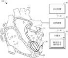
图1是根据本公开的实施例的用于映射和观察内部心脏结构的系统的示意图。1 is a schematic diagram of a system for mapping and viewing internal cardiac structures according to an embodiment of the present disclosure.
图2是根据本公开的实施例的与图1的系统结合使用的映射探针的示意图。2 is a schematic diagram of a mapping probe used in conjunction with the system of FIG. 1, according to an embodiment of the present disclosure.
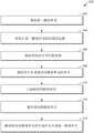
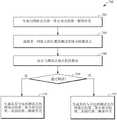
图3是描绘根据本公开的实施例的用于解剖外壳编辑的说明性的处理器实现的方法的流程图。3 is a flowchart depicting an illustrative processor-implemented method for anatomical shell editing in accordance with an embodiment of the present disclosure.
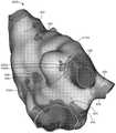
图4A-图4D是根据本公开的实施例的从不同视角示出的解剖外壳的图像。4A-4D are images of an anatomical shell shown from different perspectives, according to embodiments of the present disclosure.
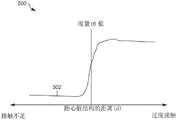
图5是根据本公开的实施例的度量(metric)的图。5 is a diagram of a metric in accordance with an embodiment of the present disclosure.
图6A-图6C示出了根据本公开的实施例的电极与心脏结构之间的不同类型的接触。6A-6C illustrate different types of contact between electrodes and cardiac structures according to embodiments of the present disclosure.
图7是描绘根据本公开的实施例的用于解剖外壳编辑的另一个说明性处理器实现的方法的流程图。7 is a flowchart depicting another illustrative processor-implemented method for anatomical shell editing in accordance with an embodiment of the present disclosure.
图8是描绘根据本公开的实施例的用于执行与测试点相关联的测试的说明性处理器实现的方法的流程图。8 is a flowchart depicting an illustrative processor-implemented method for performing tests associated with test points in accordance with an embodiment of the present disclosure.
虽然所公开的主题适合于各种修改和替代形式,但是具体实施例已经借由示例在附图中被示出并且在下面被详细描述。然而,本发明并不意图将本公开限制于所描述的特定实施例。相反,本公开旨在覆盖落入由所附权利要求限定的本公开的范围内的所有修改、等同物和替代方案。While the disclosed subject matter is amenable to various modifications and alternative forms, specific embodiments have been shown by way of example in the drawings and are described in detail below. It is not intended, however, to limit the disclosure to the particular embodiments described. On the contrary, the present disclosure is intended to cover all modifications, equivalents, and alternatives falling within the scope of the present disclosure as defined by the appended claims.
虽然术语“框(block)”在本文中可以被用于暗示说明性地采用的不同元件,但是该术语不应该被解释为暗示在此公开的各种步骤当中的或之间的任何要求或特定顺序,除非并且除了在明确提及个别步骤的顺序时。Although the term "block" may be used herein to imply various elements illustratively employed, the term should not be construed to imply any requirement or specificity among or between the various steps disclosed herein order unless and except when the order of the individual steps is explicitly mentioned.
具体实施方式Detailed ways
图1是根据本公开的实施例的用于映射心脏结构102的映射系统100的示意图。贯穿本公开,术语“心脏结构”可以指对象心脏的任何部分和/或相邻特征,诸如例如心内膜、心外膜、整个心脏、心室、心室的一部分、瓣膜、冠状窦和/或其分支(tributaries)、冠状窦的一部分和/或其分支的一部分、肺动脉和/或其他周围脉管系统等。尽管本公开讨论了使用映射系统100来映射心脏结构102,但映射系统100的实施例还可以或可替代地被用于映射其他器官和生物组织,包括但不限于肾、肺、脑、胆囊、肝、脾和/或肠等。1 is a schematic diagram of a
系统100包括映射探针14。映射探针14包括柔性导管本体18。当映射心脏结构102时,医师或医疗专业人员将导管本体18的远端插入患者的心室(例如,心脏的左心室)。当示出心脏的左心室时,可替选地,导管本体18的远端可以被布置在心脏的其他部分和/或周围脉管系统中,诸如例如左心房、右心房或者右心室、冠状窦及其分支和肺动脉。导管本体18的远端具有多电极结构20。在示出的实施例中,电极结构20采取限定开放式内部空间22的篮状形式。当电极结构20采取示出的实施例中的篮状形式时,这仅仅是示例,并且可以利用其他电极结构。例如,电极结构可以包括被布置在消融导管和/或诊断导管等上的一个或多个电极(例如,消融电极、微电极、环形电极等)。
如图1中示出的,电极结构20包括多个电极24。电极24被配置为感测穿过心脏结构102的电信号。该电信号可以在心脏的心内膜表面上和/或在心内膜表面下方的心室中被感测到。如本文所使用的,在心室内部的点处感测到的信号的映射表示被称为在心内膜表面下方。也就是说,例如,因为映射图包括表示心内膜表面的解剖外壳,并且从观察者的视角,位于腔室内而不在心内膜表面上的点将似乎在映射表面下方。As shown in FIG. 1 ,
每个信号可以与对应于信号被感测到的位置的相应位置坐标的集合相关联。相应电信号可以包括但不限于电压幅值、激活信号和一段时间内的激活信号的变化。每个相应的位置坐标可以包括三维笛卡尔坐标和/或极坐标等。在实施例中,可以使用其他坐标系。在实施例中,使用任意的原点并且相应的位置坐标是指相对于任意原点的空间中的位置。在实施例中,由于信号可以在心内膜表面上以及由心内膜表面包围的腔室中被感测到,所以相应的位置坐标可以在患者心脏的心内膜表面上和/或在心内膜表面下。Each signal may be associated with a respective set of location coordinates corresponding to the location at which the signal was sensed. The corresponding electrical signals may include, but are not limited to, voltage amplitudes, activation signals, and changes in activation signals over a period of time. Each corresponding location coordinate may include three-dimensional Cartesian coordinates and/or polar coordinates, among others. In embodiments, other coordinate systems may be used. In an embodiment, an arbitrary origin is used and the corresponding position coordinates refer to positions in space relative to the arbitrary origin. In an embodiment, since the signals can be sensed on the endocardial surface and in the chambers surrounded by the endocardial surface, the corresponding location coordinates can be on the endocardial surface of the patient's heart and/or in the endocardium under the surface.
电极24被电耦接到处理装置32。也就是说,篮状结构20上的每个电极24可以经由有线和/或无线连接可通信地被耦接到处理装置32。在存在有线连接的实施例中,来自每个电极的导线(未示出)可以延伸通过映射探针14的导管本体18并且将每个电极24电耦接到处理装置32。在存在无线连接的实施例中,发送器(未示出)可以被包括在映射探针14中,该发送器可以将来自篮状结构20上的每个电极24的感测到的信号发送到被耦接到处理装置32的接收器(未示出)。
一旦感测点(sensed point)被处理装置32从电极24接收到,处理装置32就处理感测到的信号。处理装置32根据被存储在存储器34上的解剖外壳编辑指令36处理感测点。处理装置32可以是,包括电处理器、软件处理器、通用微处理器和/或专用微处理器,或被包括在其中,并且可以包括多个处理器或核之一或者唯一处理器。经处理的信号被显示在显示装置40上。显示装置40可以包括但不限于以下显示装置之一:阴极射线管(CRT)显示器、发光二极管(LED)显示器或者液晶显示器(LCD)显示器。Once a sensed point is received from
存储器34可以以易失性和/或非易失性存储器的形式,并且可以是可移除的、不可移除的或其组合。媒体示例包括随机存取存储器(RAM);只读存储器(ROM);电子可擦除可编程只读存储器(EEPROM);闪速存储器;光学或全息介质;磁带盒、磁带、磁盘存储器或其他磁存储装置;数据传输;和/或可以被用于存储信息并且可以被处理装置32访问的任何其他介质(诸如例如量子状态存储器)等。映射指令36可以使用任何数量的不同编程环境(包括各种语言、开发套件和/或框架等)在存储器34上被编程。此处考虑的一些或全部功能还可以或可替选地以硬件和/或固件来实现。
处理装置32、存储器34和显示装置40可以通过总线42直接地和/或间接地被耦接在一起。任何数量的附加组件、不同组件和/或组件的组合也可以经由总线42被耦接到处理装置32、存储器34和显示装置40。该总线表示其可以是一个或多个总线(诸如例如地址总线、数据总线或其组合)。
图1中示出的说明性映射系统100并不意图对本公开的实施例的使用范围或功能提出任何限制。说明性映射系统100也不应被解释为具有与其中示出的任何单个组件或组件的组合有关的任何依赖性或要求。另外,在实施例中,图1中描绘的各种组件可以与其中描绘的其他组件中的各种组件(和/或未示出的组件)集成,所有这些都被认为是在本公开的范围内。例如,存储器34可以与处理装置32集成。The
图2是根据本公开的实施例的用于与图1的系统100相关联的映射探针14的示意图。映射探针14具有柔性导管本体18,其远端承载包括映射电极24的三维篮状结构20。如上所述,映射电极24感测心脏结构中的信号;并且感测到的信号经由有线和/或无线连接被发送到处理装置32。处理装置32处理感测到的信号并创建映射图,例如,如在下面对应于图3的描述中描述的。所创建的映射图的类型可以包括但不限于以下:电压映射图、激活映射图、分级映射图(fractionation map)和/或速度映射图等。FIG. 2 is a schematic diagram of a
篮状结构20包括基部构件41和端帽42,柔性样条44大体上以周向间隔的关系在基部构件41和端帽42之间延伸。如上面讨论的,篮状结构20采取限定开放式内部空间22的篮状形式。在实施例中,样条44由弹性惰性材料制成,诸如镍钛诺金属或硅橡胶,并且以弹性拉紧前(pre-tensed)状态被连接在基部构件41和端帽42之间,以弯曲并且符合它们接触的组织表面。在示出的实施例中,八个样条44形成三维结构20。在其他实施例中可以使用附加或更少的样条44,并且三维结构20可以根据任何数量的不同形状来配置,诸如例如大致球形、大致椭圆形和/或大致泪滴形等。如示出的,每个样条44承载八个映射电极24。在三维结构20的其他实施例中,可以在每个样条44上布置附加的或更少的映射电极24。在示出的实施例中,三维结构20相对较小(例如,直径为40mm或更小)。在实施例中,三维结构20较大(例如,直径40mm或更大)。The
在实施例中,可滑动护套50沿着导管本体30的主轴是可移动的。向前(即朝向远端)移动护套50导致护套50在三维结构20上移动,由此将结构20折叠成适合于引入内部空间中(诸如例如引入心脏中)的紧凑的低姿态状态。相反,向后(即朝向近端)移动护套50暴露出三维结构20,以允许结构20弹性地扩展并呈现图2中示出的预紧前位置。三维结构20的实施例的进一步细节在例如题为“Multiple Electrode Support Structures”的美国专利No.5,647,870中被公开,其全部内容通过引用并入本文。In an embodiment, the
在映射探针14使用有线连接的实施例中,信号线(未示出)可以被电耦接到每个映射电极24。该线可以延伸通过映射导管20的本体30进入手柄54中,其中它们可以被耦接到外部连接器56,该外部连接器56可以是例如多引脚连接器。连接器56将映射电极24电耦接到处理系统32。关于用于处理由映射导管生成的信号的映射系统和方法的进一步细节在例如题为“Systems and Methods for Guiding Movable Electrode Elements withinMultiple-Electrode Structure”的美国专利No.6,070,094、题为“Cardiac Mapping andAblation Systems”的美国专利No.6,233,491以及题为“Systems and Processes forRefining a Registered Map of a Body Cavity”的美国专利No.6,735,465中进行讨论,其公开内容通过引用并入本文。In embodiments where the
应该注意的是,其他电极结构可以被部署在映射导管的远端上。进一步注意的是,多个映射电极24可以布置在多于一个结构上,而不是例如图2中示出的单个映射探针14上。例如,如果在左心房内与多个映射结构进行映射,则可以使用包括承载多个映射电极的冠状窦导管和承载被定位于左心房中的多个映射电极的篮状导管的布置。作为另一示例,如果在右心房内与多个映射结构进行映射,则可以使用包括承载用于在冠状窦中定位的多个映射电极的十极(decapolar)导管和承载用于在三尖瓣环状物周围定位的多个映射电极的环形导管的布置。It should be noted that other electrode structures can be deployed on the distal end of the mapping catheter. It is further noted that
尽管映射电极24已被描述为由诸如映射探针14的专用映射探针来承载,但映射电极可以被承载在非映射专用探针或多功能探针上。例如,消融导管可以被配置为包括被布置在导管本体的远端上并且被耦接到信号处理系统32的一个或多个映射电极24。Although
图3是根据本公开的实施例的用于可调节深度的解剖外壳编辑的基于处理器的方法300的流程图。方法300的实施例可全部或部分地由映射系统(例如,图1中描绘的映射系统100)来执行。方法300包括将心脏结构的第一解剖外壳输出到显示装置(框302)。第一解剖外壳包括在多个点处与心脏结构相关联的多个电压的表示,其中多个电压由映射探针感测到。在实施例中,映射探针可以具有与以上在图1和图2中描述的映射探针14相同或相似的特性。在实施例中,心脏结构可以包括但不限于左心房的一部分、右心房的一部分、左心室的一部分、右心室的一部分、冠状窦的一部分和/或其分支的一部分、其他周围脉管系统的一部分或者左心房、右心房、左心室、右心室、冠状窦及其分支或周围脉管系统的完整腔室。3 is a flow diagram of a processor-based
由映射探针感测到的多个电压中的每个具有对应的三维位置坐标的集合。感测到的电压的三维位置坐标被称为电压被感测所在的点。在实施例中,该点可以以笛卡尔坐标表示。但是,可以使用其他坐标系。在实施例中,使用任意原点并且相对于任意原点来定义该点。在一些实施例中,该点具有不均匀的间距,而在其他实施例中,该点具有均匀的间距。在实施例中,对应于感测到的电压的点可以位于心脏的心内膜表面上和/或位于心脏的心内膜表面下方。Each of the plurality of voltages sensed by the mapping probe has a corresponding set of three-dimensional position coordinates. The three-dimensional positional coordinates of the sensed voltage are referred to as the point at which the voltage is sensed. In an embodiment, the point may be represented in Cartesian coordinates. However, other coordinate systems can be used. In an embodiment, the point is defined using and relative to an arbitrary origin. In some embodiments, the dots have non-uniform spacing, while in other embodiments, the dots have uniform spacing. In embodiments, the point corresponding to the sensed voltage may be located on and/or below the endocardial surface of the heart.
在实施例中,解剖外壳可以至少部分地基于电信号来生成。该外壳可以至少部分地使用任何数量的其他信号和/或技术等来生成。例如,实施例可以利用阻抗映射技术来生成该外壳。在实施例中,表面可以被适配在与电信号相关联的一个或多个点上以生成表示心内膜表面的外壳。在实施例中,对应点处的电信号的一个或多个特征可被包括在心内膜表面的映射图中。例如,实施例可以包括在外壳上显示表示从电信号提取的特征诸如例如电压、激活幅度和/或信号清晰度等的注释。作为另一个示例,表面可以适配在与电信号相关联的一个或多个点上以生成表示心外膜表面或其他易激动的心脏组织的外壳。In embodiments, the anatomical shell may be generated based at least in part on electrical signals. The enclosure may be generated, at least in part, using any number of other signals and/or techniques, or the like. For example, embodiments may utilize impedance mapping techniques to generate the enclosure. In an embodiment, the surface may be adapted at one or more points associated with the electrical signal to generate a shell representing the endocardial surface. In an embodiment, one or more features of the electrical signal at the corresponding point may be included in the map of the endocardial surface. For example, embodiments may include displaying annotations on the housing representing features extracted from the electrical signal, such as, for example, voltage, activation amplitude, and/or signal clarity. As another example, a surface may be adapted at one or more points associated with an electrical signal to create a shell representing an epicardial surface or other excitable cardiac tissue.
在图4A中示出了被输出到显示装置的说明性的第一解剖外壳400A的图像。不同的灰度阴影对应于由映射探针感测到的不同电压。更具体地,第一部分402、第二部分404、第三部分406和第四部分408每个都具有不同的相应电压幅值(或电压幅值的范围)。第一部分402具有比第二部分404更高的电压幅值,第二部分404具有比第三部分406更高的电压幅值,并且第三部分406具有比第四部分408更高的电压。An image of an illustrative first
方法300的实施例还包括从用户输入装置接收对第一解剖外壳的区域的选择(框304)。被用于进行选择的用户输入装置可以包括鼠标和/或触摸屏等,其被用于操纵在由显示装置提供的用户界面上提供的选择工具。选择工具可以包括例如笔刷、光标(用于通过在区域周围绘制自由形状来包围所选区域)和/或可扩展多边形选择工具等,并且在实施例中可以选自多个可选的选择工具。在实施例中,选择工具可以具有可调节的大小、行为和/或其其他特性。以这种方式,例如,用户可以选择所期选择工具及其大小。选择解剖外壳的表面的区域可以包括例如使用鼠标或触摸屏装置操纵光标来环绕解剖外壳的表面的区域和/或使用输入装置操纵笔刷来刷过表面的区域等。Embodiments of
参照图4A,例如,示出了所选区域410A。所选区域410A包括三个区域:第一区域402A、第二区域404A和第三区域406A,每个都具有不同电压的表示。例如,可以使用不同的颜色、阴影和/或纹理等来表示不同的电压。第一区域402A具有与区域402相同的电压,其高于具有与区域404相同的电压的第二区域404A的电压。并且,第二区域404A具有比第三区域406A更高的电压,第三区域406A具有与区域406相同的电压。从在三个区域402A、404A、406A中感测到的不同电压幅值,用户可以确定出系统没有准确地表示所选区域410A中的所有电压幅值。特别地,例如,用户可以确定出第二区域404A和第三区域406A应该具有更接近第一区域402A的电压幅值。可替选地或另外地,熟悉心脏解剖结构的用户可以认识到解剖外壳400A未被准确地表示,这是因为例如用户知道心室在第二区域404A和第三区域406A附近具有内部突起,其没有被示出在外壳400A上。然而,通过采用本文提供的实施例,可以编辑解剖外壳400A以更准确地表示心脏结构,如下面解释的。Referring to Figure 4A, for example, selected
在一些实施例中,方法300还可以包括从输入装置接收对解剖外壳的表面的区域的选择的修改。响应于接收到修改,可以对解剖外壳的表面的区域进行修改的选择。能够修改该选择对于选择太大或太小的区域的用户来说可能是有用的,用于促进增量选择和/或促进更准确的选择等。在实施例中,对选择的修改可以包括对选择的目标深度的修改和/或对所选表面的区域的大小的修改等。例如,在实施例中,修改可以包括对解剖外壳的表面的附加区域的选择。类似于选择上述部分,可以使用鼠标或触摸屏等来修改选择。在实施例中,修改所选部分可以包括取消选择所选区域并且然后重新选择区域。在实施例中,修改选择可以包括通过改变选择的边界来修改选择。在实施例中,这可以例如通过在所选区域的边界的一部分上点击并将该边界的所选部分拖动到新位置来完成。In some embodiments, the
方法300的实施例还包括从用户输入装置接收所选区域的目标深度(框306)。使用接收到的目标深度,所选区域410A可以被移除至基于目标深度并且遵循解剖外壳400A的轮廓的编辑深度。在实施例中,被移除的部分包括表面的所选区域(或修改的所选区域)并向内延伸到编辑深度。编辑深度可以包括至少一个有限深度,并且对应于解剖外壳的表面的轮廓,可以改变。也就是说,例如,编辑深度可以是沿着与解剖外壳的表面垂直的轴在解剖外壳的表面上的点与从解剖外壳的表面向内(即,在表面下方)的点之间的距离。以这种方式,编辑深度可以随着表面的轮廓而改变。Embodiments of
根据实施例,编辑深度可以是可调节的和/或可选的。也就是说,例如,用户可以经由用户界面输入和/或选择目标深度,使得对应于所选区域中的每个点的编辑深度可以至少近似等于目标深度(例如,等于目标深度、在目标深度的至少0.1毫米内、在目标深度的至少0.5毫米内和/或在目标深度的1毫米内等)。在实施例中,目标深度可以小于一毫米、至少一毫米并且不多于十毫米和/或至少一毫米并且不多于五毫米等。Depending on the embodiment, the editing depth may be adjustable and/or selectable. That is, for example, the user may input and/or select the target depth via the user interface such that the edit depth corresponding to each point in the selected area may be at least approximately equal to the target depth (eg, equal to the target depth, at the target depth within at least 0.1 mm, within at least 0.5 mm of the target depth and/or within 1 mm of the target depth, etc.). In embodiments, the target depth may be less than one millimeter, at least one millimeter and no more than ten millimeters, and/or at least one millimeter and no more than five millimeters, or the like.
在实施例中,方法300可以包括在选择区域410A之后、在选择区域410A之前和/或在显示解剖外壳400A的任何时间处从用户输入装置接收用于旋转显示的解剖外壳400A的命令。方法300可以包括基于该命令生成第一解剖外壳的旋转视图。在实施例中,解剖外壳400A可以以任何方向旋转。另外,可以采用调节显示图像的任何数量的其他方法,诸如例如缩放、平移(pa)和/或反转等。另外,可以实现、调节和/或选择任何数量的不同颜色和/或纹理等以用于表示各种显示的特征,诸如例如解剖特征、电压幅值、信号清晰度、激活幅度和/或激活传播等。In an embodiment,
在实施例中,方法300可以包括从用户输入装置接收用于生成修改的解剖形状的命令(框308)。因此,代替一旦区域410A被选择就自动生成修改的形状,而是基于处理器的方法等待,直到用户输入用于生成修改的解剖形状的命令为止。这可以用于确定所选区域410A是否是用户想要选择的内容。本公开的实施例还包括基于所选区域自动生成修改的解剖形状。In an embodiment,
方法300的实施例还包括生成修改的(第二)解剖外壳,其包括由映射探针在所选部分的大约有限深度处感测到的至少一个电压(框310)。也就是说,在实施例中,除了所选部分410A显示由映射探针在近似有限深度处感测到的一个或多个电压之外,修改的解剖外壳还具有与第一解剖外壳400A相同的形状和电压。在实施例中,修改的解剖外壳可以在形状上改变以指示特征和/或结构等的存在或不存在。在实施例中,所选区域可以在修改的解剖外壳中被移除至编辑深度,其中在编辑深度处生成新的表面区域,在其上显示相应的电压值。在生成修改的解剖形状之后,方法300的实施例包括将修改的解剖外壳输出到显示装置(框312)。显示装置可以具有与图1中的显示装置40相同的一些或全部特性。Embodiments of
在图4B中示出了输出到显示装置的示例性修改的解剖外壳400B的图像。如示出的,修改的解剖外壳400B的所选区域410B具有与第一解剖外壳400A的所选区域410A不同的电压幅值。特别地,所选区域410B现在包括具有与第四区域408相同的电压幅值的区域408B和具有与第三区域406相同的电压幅值的区域406B。在实施例中,用户和/或处理装置(例如,图1中所描绘的处理装置32)可以确定出由于区域406B、408B具有这样的低电压幅值,所以区域406B、508B可能对应于血池。以这种方式,由于区域406B、408B具有大致对应于在血池中的电压幅值感测的电压幅值,所以用户可以例如确定出所选目标深度可能太深。结果,在实施例中,方法300可以包括从用户输入装置接收命令以撤消修改的解剖外壳的生成并且再生第一解剖外壳(框314)。当生成第一解剖外壳时,它可以被输出到显示装置供用户查看。An image of an exemplary modified
在用户选择撤消修改的解剖外壳400B的生成之后,用户然后可以通过增大或减小所选区域410A的边界或者改变所选区域410A的深度来修改所选区域410A。在图4A-图4D中示出的示例中,修改了目标深度。如图4C中示出的,可以使用修改的选择(例如,修改的目标深度)来创建另一(第三)修改的解剖外壳400C。如可以看出的,所选区域410C中包括更高的电压幅值。特别地,区域402C具有与第一区域402相同的电压幅值,并且区域404C具有与第二区域404相同的电压幅值。After the user selects to undo the generation of the modified
图4D是示出了所选区域410C的修改的解剖外壳400C的另一旋转视图。由于这种旋转,用户可以辨别出接收到的修改的目标深度导致了修改的解剖外壳400C,该修改的解剖外壳400C可能比第一解剖外壳400A和修改的解剖外壳400B在形状上更接近实际心室。另一方面,如果尝试了几个有限深度,其没有改善图4A中的所选部分410A的电压幅值,则医生可能能够辨别出所选部分410A是患病的并且表现出低于理想电压激活。以这种方式,由于所显示的表示的准确性提高,医师或其他医疗专业人员可以更好地对此心室进行任何必要的心脏治疗。FIG. 4D is another rotational view of the modified
虽然以上描述了电压引导的解剖外壳编辑的用户指导方法的实施例,但是本公开的实施例包括自动解剖外壳编辑。在实施例中,例如,处理装置(例如,图1中描绘的处理装置32)可以被配置为测试生成的解剖外壳的心内膜表面下方的点以确定那里是否存在解剖特征和/或确定各种点和深度等处的电压幅值。在实施例中,处理装置可以被配置为利用任何数量的不同度量,诸如例如电压幅值、激活幅度、信号清晰度、心外带(out-of-cardiac-band)阻抗测量结果、映射探针的接触力测量结果和/或基于位置的心脏运动测量结果等。度量的值可以在任何数量的各种算法中被利用以识别内部结构等。While embodiments of user-guided methods of voltage-guided anatomical shell editing are described above, embodiments of the present disclosure include automated anatomical shell editing. In embodiments, for example, a processing device (eg,
在实施例中,诸如以上列出的一个或多个所选度量可能倾向于表现出与组织的接近度将与有意义的异常值(outlier)一致的行为,从而允许智能注释和聚合。度量也可能是这些数量的某种组合。在实施例中,该度量可以是R3→R函数,使得针对度量被测量所在的每个点记录3D位置以及标量值。In an embodiment, one or more selected metrics, such as those listed above, may tend to exhibit behavior where the proximity to the tissue will be consistent with meaningful outliers, allowing for intelligent annotation and aggregation. The measure could also be some combination of these quantities. In an embodiment, the metric may be anR3 →R function such that a 3D position and a scalar value are recorded for each point at which the metric is measured.
在实施例中,可以选择度量以使得可以确定电极(和/或映射探针)与特定点(例如,测试点)处的心脏结构之间的接触的可能性、接近度和/或程度。例如,通过确定电极(和/或映射探针)与心脏结构之间的接触的可能性、接近度和/或程度,可以确定所生成的解剖外壳是否是心脏结构的实际形状的扭曲的版本。例如,关于由该度量的实施例表现出的轮廓的观察被体现在图5中。图5是示出了根据本公开的实施例的可以被用于对确定电极(和/或映射探针)与心脏结构之间的接触的可能性、接近度和/或程度的技术进行建模的度量502的图500。In embodiments, metrics may be selected such that the likelihood, proximity, and/or degree of contact between electrodes (and/or mapping probes) and cardiac structures at particular points (eg, test points) may be determined. For example, by determining the likelihood, proximity, and/or extent of contact between the electrodes (and/or mapping probes) and the cardiac structure, it may be determined whether the generated anatomical shell is a distorted version of the actual shape of the cardiac structure. For example, observations regarding the profile exhibited by an embodiment of this metric are embodied in FIG. 5 . 5 is a diagram illustrating techniques that may be used to model the likelihood, proximity, and/or extent of contact between electrodes (and/or mapping probes) and cardiac structures in accordance with embodiments of the
如图5中示出的,对应于度量的通用数学模型可以是,例如:As shown in Figure 5, a general mathematical model corresponding to a metric can be, for example:

其中d是测量出的信号的位置与心脏结构的距离,ε是第一阈值,并且δ是第二阈值。类似的,where d is the distance of the position of the measured signal from the cardiac structure, ε is the first threshold, and δ is the second threshold. akin,

即,系统的实施例可以利用处于梯度中的信息。例如,在血池中(例如,在接触不足的情况下),度量的值可以被认为是围绕某个低平均值大致均匀的,并且相反,针对过度接触,该值可以被认为是围绕某个高平均值大致均匀的。可以认为心内膜表面处于垂直轴附近(或例如在垂直轴的ε内)。如果假定通过密度进行线性化,则这个1维模型可以例如借由空间量化扩展到3D。也就是说,例如,可以将通过类似的广义3D梯度描述的广义3D情况减少为在所选点的集合之间取得的线性梯度的集合。That is, embodiments of the system may utilize information that is in the gradient. For example, in a blood pool (eg, in the case of under-contact), the value of the metric can be considered to be roughly uniform around some low average, and conversely, for over-contact, the value can be considered to be around some High averages are roughly uniform. The endocardial surface can be considered to be near the vertical axis (or eg within ε of the vertical axis). If linearization by density is assumed, this 1-dimensional model can be extended to 3D, eg by spatial quantization. That is, for example, a generalized 3D situation described by a similar generalized 3D gradient can be reduced to a set of linear gradients taken between sets of selected points.
例如,可以选择度量502,使得当在映射电极和心脏结构之间存在优选的接触量(或可能性)时,度量502的梯度比在映射电极不与心脏结构接触或扩张心脏结构时(例如,在过度接触的情况下)的度量502的梯度更大并且超过阈值。在实施例中,感测到的电信号可以表现出图5中的度量502的属性并且可以被选择为度量。在实施例中,被选择为度量的感测到的电信号可以包括但不限于以下中的一个或多个:心外带阻抗测量结果、单极电极激活电压测量结果、映射探针的接触力测量结果和基于位置的心脏运动测量结果。For example, the metric 502 can be selected such that when there is a preferred amount (or likelihood) of contact between the mapping electrode and the cardiac structure, the gradient of the metric 502 is greater than when the mapping electrode is not in contact with or expanding the cardiac structure (eg, In the case of over-contact), the gradient of the metric 502 is larger and exceeds the threshold. In an embodiment, the sensed electrical signal may exhibit the properties of metric 502 in FIG. 5 and may be selected as the metric. In an embodiment, the sensed electrical signal selected as a metric may include, but is not limited to, one or more of the following: epicardial band impedance measurements, monopolar electrode activation voltage measurements, mapping probe contact force Measurements and location-based cardiac motion measurements.
参考图6A-图6C,例如,示出了电极602A-602C与心脏结构604A-604C之间的三种类型接触。在实施例中,电极602A-602C可以表示多于一个电极、映射探针和/或导管尖端等。为了清楚起见,讨论将涉及电极,但是这个讨论并不意味着限制本公开的实施例的范围,并且应该理解,类似的讨论可以适用于多个电极、映射探针和/或导管等。对于这个示例,假定生成了具有第一表面的解剖形状,该第一表面与由映射探针感测到的最外面的点相交,并且该度量是感测到的电压。6A-6C, for example, three types of contacts between
参考图6A,该实施例中的电极602A在感测点606A处具有与心脏结构604A的所期接触量。特别地,电极602A在感测点606A处接触心脏结构604A,但不推挤心脏表面604A并使其扭曲。因此,基于由具有与心脏结构604A的这种类型的接触的映射电极602A感测到的信号的所生成的解剖外壳可以非常类似于在感测点606A处的心脏结构604A的实际形状。也就是说,例如,感测点606A可以被视为用于显示解剖外壳的表面或网格上的点的适当点。Referring to Figure 6A,
根据实施例,为了确定感测点606A是否是适当的表面点,基于如上面讨论的一个或多个度量的梯度的测试可以关于测试点610A来执行。特别地,可以选择具有感测点606A的位置的测试邻域内的位置的测试点610A。由于感测点606A是由映射探针感测到的最外面的点之一,所以测试点将相对于感测点606A位于心脏结构表面604A下方。由于感测点606A在心脏结构804A的表面上,所以位于表面604A下方的任何点可以位于心脏结构604A的血池608A中。血液通常表现出明显低于在心脏结构604A的表面(例如,心内膜)上感测到的电压的电压。由于在血液中测量出的电压通常明显低于在心脏结构604A的表面上测量出的电压,因此在感测到的电压的两个值(即,感测点606A处的度量的值和测试点610A的值)之间可能存在陡峭的梯度。如果梯度超过阈值,则可以确定出感测点606A位于心脏结构604A的表面的阈值距离内。According to an embodiment, in order to determine whether sensed point 606A is a suitable surface point, a test based on the gradient of one or more metrics as discussed above may be performed with respect to test
参考图6B,在该实施例中,电极602B正接触心脏结构604B,但是也推动心脏结构604B并使其扭曲。因此,基于由具有与心脏结构604B的这种类型的接触的映射电极602B感测到的信号的所生成的解剖外壳将产生大于心脏结构604B在感测点606B处的实际形状的解剖外壳。换句话说,感测点606B可能不是由表面604B相交的适当点。为了确定生成的解剖外壳是否是心脏结构604B在感测点606B处的实际形状的扭曲形状,可以使用如上面讨论的度量相对于测试点610B来执行测试。Referring to Figure 6B, in this embodiment, electrode 602B is contacting
在实施例中,可以做出关于电极602B是否正触摸心脏结构604B的表面的确定。也就是说,由于电极602B正触摸心脏结构604B的表面,因此电压将在感测点606B处被感测,其明显高于感测点606B感测血池608B中的电压时的情况。因此,可以确定出电极602B正触摸心脏结构604B的表面。另外地或可替选地,可以利用力感测度量和/或阻抗度量等来确定电极602B是否接触心脏结构604B的表面。在实施例中,在做出该确定之后,可以执行测试。In an embodiment, a determination may be made as to whether electrode 602B is touching the surface of
特别地,可以选择位于感测点606B的测试邻域内的测试点610B。由于感测点606B是由映射探针感测到的最外面的点之一,因此所选点将相对于感测点606B位于心脏结构604B的表面下方。假定由映射探针感测到合适密度的信号,由于感测点606B正使心脏结构604B的表面扩张,所以例如可以感测到测试点610B和对应的电压刚刚触摸心脏结构604B的表面(类似于图6A中示出的配置),并且不会使心脏结构604B的表面扩张。因此,测试点610B可以具有与感测点606B的电压类似的电压,并且这两个值的梯度可能不超过阈值。在该示例中,可以使用解剖外壳的表面相交的点的集合中的感测点606B代替测试点610B,这是由于该梯度不超过阈值并且由于感测点606B正触摸心脏结构的表面604B,如在感测点606B处感测到的电压确定出的。通过使用测试点610B代替感测点606B,解剖外壳可以更准确地表示心脏结构604B的实际形状。In particular,
参考图6C,该实施例中的电极602C不接触心脏结构604C。因此,基于由具有与心脏结构604C的这种类型的接触的映射电极602C感测到的信号的所生成的解剖外壳可以产生小于心脏结构604C在该感测点606C处的实际形状的解剖外壳。为了确定所生成的解剖外壳是否是心脏结构604C在感测点606C处的实际形状的扭曲形状,可以使用如上面描述的度量相对于测试点610C来执行测试。Referring to Figure 6C,
在一些实施例中,在执行测试之前,可以执行关于电极602C是否正触摸心脏结构604C的表面的确定。也就是说,由于电极602C位于血池608C中并且不触摸心脏结构604C的表面,因此可以在感测点606C处感测电压,其明显小于如果感测点606C触摸心脏结构604C的表面时的情况。另外地或可替选地,可以利用力感测度量和/或阻抗度量等来确定电极602C是否接触心脏结构604C的表面。因此,可以确定出电极602C不触摸心脏结构604C的表面。在实施例中,当做出电极606C不触摸心脏结构604C的确定时,可以不执行测试。相反,医生或其他医疗专业人员可以选择更加彻底地将心脏结构604C映射到感测点606C附近。在实施例中,如果执行测试,则可以确定出感测点606C不在心脏结构604C的表面上,这是由于血池中的测试点610B处的电压将类似于感测点606C处的电压,并且因此该度量的梯度将会很低并且不超过阈值。In some embodiments, prior to performing the test, a determination may be performed as to whether
在实施例中,处理装置32可以被配置为通过使用一个或多个人工智能(即,机器学习)技术和/或分类器等来自动提高其算法的准确性。在实施例中,例如,处理装置可以使用一个或多个监督和/或无监督技术,诸如例如支持向量机(SVM)、k-最近邻技术和/或人工神经网络等。在实施例中,分类器可以使用来自用户的反馈信息和/或其他度量等来训练和/或改编。In embodiments, the
图7是根据本公开的实施例的用于可调节深度解剖外壳编辑的基于处理器的方法700的流程图。方法700的实施例可全部或部分地由映射系统(例如,图1中描绘的映射系统100)来执行,其可包括处理装置(例如,图1中描绘的处理装置32)。如上所述,在实施例中,所生成的解剖外壳可以包括未准确地表示从其生成解剖外壳的心脏组织的心内膜表面的实际形状的点和/或区部。方法700的实施例可以促进确定所生成的解剖外壳的各个点和/或区部是否是正被映射的心脏组织的实际形状的准确表示。方法700的实施例使用与由网格(并且例如解剖外壳的表面)相交的各个点相关联的电数据,以及来自解剖外壳的表面下方的测试点(例如,未被网格相交的点)的电数据以确定解剖外壳的表面是否应该为了更准确地表示心脏组织的映射图而与一个或多个测试点而不是一个或多个网格点相交。7 is a flowchart of a processor-based
如图7中示出的,方法700包括生成第一解剖外壳,其中第一解剖外壳包括与网格点的第一集合相交的第一表面,网格点的第一集合对应于多个信号,其中每个信号包括至少一个相应的感测到的电信号(框702)。在实施例中,可以使用具有与上面描述的映射探针14相同或相似的特性的映射探针来感测与网格点的第一集合相对应的信号。如上面在图3中描述的,每个网格点具有位置坐标的相应集合。在实施例中,网格点的第一集合的网格点可以是体素或空间中的点。第一解剖外壳的第一表面可以在网格点的相应位置坐标处被拟合到网格点的第一集合。在实施例中,网格点的第一集合是与由映射探针感测到的信号相对应的所有点的子集。如下所述,由映射探针感测到的未包括在第一多个网格点中的至少一些点可以被用作测试点。As shown in FIG. 7,
方法700还包括选择测试点,其中第一表面不与测试点相交(框704)。如上所述,方法700可以被用于确定生成的解剖外壳的表面是否应该与网格点的第一集合的第一网格点相交,或者替代地该表面是否应该与另一个点、例如测试点相交。像这样,在实施例中,测试点的选择可以基于第一网格点。也就是说,在实施例中,可以基于测试点的位置是否位于第一网格点的位置的测试邻域内来选择测试点。在实施例中,测试邻域可以是其中心位于第一网格点的位置处并且可以具有一些预定的、可选的和/或可调节的半径(例如2毫米)的球体。The
测试点的位置可以位于第一生成的解剖外壳的心内膜表面的下方。在实施例中,可以选择具有位于第一网格点处的网格的表面的法线的相反方向上的位置的测试点。在实施例中,测试点可以具有以下位置,该位置位于最接近于由映射探针感测到的位于法线的相反方向上的所有点的第一网格点的位置。以这种方式,例如,如果所生成的第一解剖外壳与由映射探针感测到的最外面的点相交并且确定出解剖外壳的表面应该与测试点而不是第一网格点相交,则解剖外壳的表面将向内调节以与测试点相交。The location of the test point may be below the endocardial surface of the first generated anatomical shell. In an embodiment, a test point may be selected that has a position in the opposite direction of the normal to the surface of the grid at the first grid point. In an embodiment, the test point may have a position that is closest to the first grid point of all points sensed by the mapping probe that lie in the opposite direction of the normal. In this way, for example, if the generated first anatomical shell intersects the outermost points sensed by the mapping probe and it is determined that the surface of the anatomical shell should intersect the test points rather than the first grid points, then The surface of the anatomical shell will adjust inward to meet the test point.
为了确定所生成的解剖外壳是否应该与测试点而不是第一网格点相交,方法700包括执行与测试点相关联的测试(框706)。在实施例中,关于图6A-图6C,测试可以包括多个步骤,诸如例如下面关于图8和/或以上讨论的步骤的实施例。可以使用任何数量的其他测试、算法和/或机器学习技术等来确定网格是否应该被调节为与测试点相交。To determine whether the generated anatomical hull should intersect the test point instead of the first grid point, the
在执行与测试点相关联的测试之后,方法700包括确定测试是否通过(框708)。如果测试通过,则方法700包括生成第二解剖外壳,该第二解剖外壳包括与网格点的第二集合相交的第二表面,其中网格点的第二集合包括测试点(框710)。在实施例中,可以替换测试点来代替第一网格点。另外,在实施例中,系统可以执行内插和/或其他平滑技术以平滑测试点的位置周围的表面。在实施例中,方法700可以相对于被包括在网格点的第一集合中的其他网格点执行。另一方面,如果测试未通过,则方法700包括生成具有与网格点的第二集合相交的第二表面的第二解剖外壳,其中网格点的第二集合不包括测试点(框712)。在实施例中,第一网格点可以被包括在网格点的第二集合中。例如,在这种情况下,网格点的第二集合可以与网格点的第一集合相同。After performing the test associated with the test point, the
如上所述,图8是描绘根据本公开的实施例的用于执行与测试点相关联的测试的说明性处理器实现的方法800的流程图。方法800包括确定对应于第一网格点的度量的第一值(框802)。确定出的度量的第一值可以是第一网格点处的度量的幅值。例如,在实施例中,度量的第一值可以是对应于网格点的至少一个相应感测到的电信号的幅值。方法800还包括确定对应于测试点的度量的第二值(框804)。As noted above, FIG. 8 is a flowchart depicting an illustrative processor-implemented
如图8中示出的,方法800还包括基于第一值和第二值来计算度量的梯度特征(框806)。在实施例中,梯度特征可以是第一值和第二值的差值除以第一网格点和测试点之间的距离。方法800的实施例还包括确定梯度特征是否满足条件。在实施例中,当梯度特征的绝对值超过阈值时,该条件可以被满足,其中梯度的值低于负阈值等。As shown in FIG. 8, the
例如,在实施例中,测试可以包括选择步长s,其可以是例如某个距离(例如,0.1mm、0.2mm、1mm等)。然后,针对具有法线n的每个网格顶点位置x,方法800的实施例可以包括评估针对x和x-sn的度量f。在实施例中,可以通过将网格中收集到的信号特征内插到网格表面来生成解剖外壳,在这种情况下,评估可以是基于网格的,并且可以如下面更详细地描述的那样相对于基于网格的测试来执行。在实施例中,评估可以是基于网格的,诸如例如某个半径r内的邻域的距离加权平均(例如2mm)。方法800可以包括计算梯度特征:For example, in an embodiment, the test may include selecting a step size s, which may be, for example, a certain distance (eg, 0.1 mm, 0.2 mm, 1 mm, etc.). Then, for each mesh vertex positionx with normaln , an embodiment of

其中,如果G<-Gm(其中-Gm是某个负阈值),则方法800可以包括将顶点重新定位在x-sn处,并且在该顶点处重复该过程。否则,可以选择一个新的顶点,并且针对该新顶点应用该测试。Wherein, if G<-Gm (where-Gm is some negative threshold),
如上面指出的,一些映射系统可以利用基于网格的数据聚合方案。在这样的系统中,针对每个收集到的电极/空间记录,实施例可以包括建立预定的影响半径,使得度量被分配给周围体素的集合。如果体素受到多于一个电极采集的影响,则实施例可以包括对测量结果进行平均。这可能基于这样的理念:组织形状和位置不一定随着时间而改变,并且因此可以假定应该考虑所有的测量结果,而不仅仅是最新的或者第一个。As noted above, some mapping systems may utilize grid-based data aggregation schemes. In such a system, for each collected electrode/spatial recording, embodiments may include establishing a predetermined radius of influence such that metrics are assigned to sets of surrounding voxels. If a voxel is affected by more than one electrode acquisition, embodiments may include averaging the measurements. This may be based on the idea that tissue shape and position do not necessarily change over time, and therefore it can be assumed that all measurements should be considered, not just the latest or the first.
在实施例中,针对具有为其自身及其邻域的分配的有效度量的每个体素vi,测试可包括计算交叉体素梯度:In an embodiment, for each voxel vi with an assigned valid metric for itself and its neighbors, the test may include computing the cross-voxel gradient:

其中vc是面向体素,并且d是距离。该测试可能还包括发现wherevc is the oriented voxel, and d is the distance. The test may also include finding
GM=max{G(vi)}GM =max{G(vi )}
其是体素处理的度量值。在数据密度足够的情况下,该测量结果可以提供体素在梯度曲线上的位置的良好指示,并因此提供任何生成的网格三角形的良好指示。在实施例中,系统还可以或可替选地考虑最大梯度的方向,其例如可以被表示为在两个相邻体素之间形成的向量。It is a measure of voxel processing. With sufficient data density, this measurement can provide a good indication of the position of the voxels on the gradient curve, and thus of any resulting mesh triangles. In an embodiment, the system may also or alternatively consider the direction of maximum gradient, which may for example be represented as a vector formed between two adjacent voxels.
基于上述度量值分配,可以采取任何数量的细化步骤。在实施例中,细化步骤可以基于阈值,该阈值可以是可变的或固定的、预定的、可调节的和/或可选的等。例如,在实施例中,可以简单地关闭具有低值的体素。在实施例中,可以使用我们现有的网格生成算法来生成整个其他表面(其中将iso等级作为归一化阈值应用于归一化网格),与标准重构一起被示出,其中用户选择重构的哪些区域捕捉到新的表面。Based on the above metric assignments, any number of refinement steps can be taken. In an embodiment, the refinement step may be based on a threshold, which may be variable or fixed, predetermined, adjustable and/or selectable, and the like. For example, in an embodiment, voxels with low values may simply be turned off. In an embodiment, our existing mesh generation algorithm can be used to generate the entire other surface (where the iso level is applied as a normalization threshold to the normalized mesh), shown along with the standard reconstruction, where the user Choose which areas of the reconstruction snap to the new surface.
在实施例中,可以使用如其获取的某种形式度量的直接可视化来指示瞬时接近心脏组织(例如,当前感测到的心外带外阻抗值的平均值)。然而,在一些情况下,这样的实施例可能具有一些缺陷,这是因为例如针对一些度量,任何给定的瞬时测量结果的集合可能由于噪声和/或探针附近的其他环境信号而失真(例如,消融能量的施加是许多这样的影响的原因)。像这样,在实施例中,精细的解剖外壳可以利用上述度量中的一个或多个度量在时间和空间上的聚合,以允许处理这样的异常值,导致心脏组织的形状和位置的准确近似。结合通常被认为是稳定和可靠的探针的获取位置,利用上述一个或多个指标在时间和空间上的聚合,通过计算与精细的解剖外壳的接近度而可以生成接近心脏组织的替代指示。实施例可以使用这种接近心脏组织的替代指示来通过其自身或结合其他方法(例如,通过检测正在施加消融能量,或者通过感测获取的映射探针信号上的噪声的升高水平)通过决定在检测到噪声和/或环境信号时进行切换来克服上述挑战(即,由探针附近的噪声和/或其他环境信号引起的失真)。In an embodiment, a direct visualization of some form of metric as it is acquired may be used to indicate instantaneous proximity to cardiac tissue (eg, the average of currently sensed extra-cardiac out-of-band impedance values). However, in some cases, such embodiments may have some drawbacks because, for example, for some metrics, any given set of instantaneous measurements may be distorted by noise and/or other environmental signals in the vicinity of the probe (eg , the application of ablation energy is responsible for many of these effects). As such, in embodiments, the fine anatomical shell may utilize the aggregation of one or more of the metrics described above in time and space to allow processing of such outliers, resulting in an accurate approximation of the shape and location of cardiac tissue. Using the aggregation of one or more of the metrics described above in time and space, in conjunction with the acquisition location of the probe, which is generally considered to be stable and reliable, a surrogate indication of proximity to cardiac tissue can be generated by calculating the proximity to the fine anatomical shell. Embodiments may use this surrogate indication of proximity to cardiac tissue to determine by itself or in combination with other methods (eg, by detecting that ablation energy is being applied, or by sensing an elevated level of noise on the acquired mapping probe signal). Switching upon detection of noise and/or ambient signals overcomes the challenges described above (ie, distortion caused by noise and/or other ambient signals near the probe).
在不背离本公开的范围的情况下,可以对所讨论的示例性实施例进行各种修改和添加。例如,虽然上面描述的实施例涉及特定特征,但是本公开的范围还包括具有特征的不同组合的实施例和不包括所有描述的特征的实施例。因此,本公开的范围旨在涵盖落入权利要求范围内的所有这些替代、修改和变化以及其所有等同物。Various modifications and additions may be made to the exemplary embodiments discussed without departing from the scope of the present disclosure. For example, although the embodiments described above refer to specific features, the scope of the disclosure also includes embodiments having different combinations of features and embodiments that do not include all of the described features. Accordingly, the scope of the present disclosure is intended to cover all such alternatives, modifications and variations as fall within the scope of the claims, as well as all equivalents thereof.
Claims (14)
Applications Claiming Priority (3)
| Application Number | Priority Date | Filing Date | Title |
|---|---|---|---|
| US201562233347P | 2015-09-26 | 2015-09-26 | |
| US62/233,347 | 2015-09-26 | ||
| PCT/US2016/053633WO2017053927A1 (en) | 2015-09-26 | 2016-09-25 | Systems and methods for anatomical shell editing |
Publications (2)
| Publication Number | Publication Date |
|---|---|
| CN108140265A CN108140265A (en) | 2018-06-08 |
| CN108140265Btrue CN108140265B (en) | 2022-06-28 |
Family
ID=57130448
Family Applications (1)
| Application Number | Title | Priority Date | Filing Date |
|---|---|---|---|
| CN201680056008.7AActiveCN108140265B (en) | 2015-09-26 | 2016-09-25 | System and method for anatomical shell editing |
Country Status (5)
| Country | Link |
|---|---|
| US (1) | US10621790B2 (en) |
| EP (1) | EP3353753B1 (en) |
| JP (1) | JP6691209B2 (en) |
| CN (1) | CN108140265B (en) |
| WO (1) | WO2017053927A1 (en) |
Families Citing this family (9)
| Publication number | Priority date | Publication date | Assignee | Title |
|---|---|---|---|---|
| JP6739346B2 (en) | 2014-03-25 | 2020-08-12 | アクタス メディカル インクAcutus Medical,Inc. | Method of operating system of cardiac analysis user interface |
| WO2017053924A1 (en)* | 2015-09-26 | 2017-03-30 | Boston Scientific Scimed Inc. | Adjustable depth anatomical shell editing |
| US10469511B2 (en)* | 2016-03-28 | 2019-11-05 | Cisco Technology, Inc. | User assistance coordination in anomaly detection |
| US10679372B2 (en) | 2018-05-24 | 2020-06-09 | Lowe's Companies, Inc. | Spatial construction using guided surface detection |
| JP2022529908A (en)* | 2019-04-18 | 2022-06-27 | アクタス メディカル インク | System for generating composite maps |
| US11253183B2 (en)* | 2019-10-16 | 2022-02-22 | Biosense Webster (Israel) Ltd. | Data reuse for filling in missing data points |
| JP6928399B1 (en)* | 2020-06-22 | 2021-09-01 | ネットビジネスコンサルティング株式会社 | Blocking device and manufacturing method of blocking device |
| US12189915B2 (en) | 2022-06-24 | 2025-01-07 | Lowe's Companies, Inc. | Simulated environment for presenting virtual objects and virtual resets |
| US12211161B2 (en) | 2022-06-24 | 2025-01-28 | Lowe's Companies, Inc. | Reset modeling based on reset and object properties |
Citations (3)
| Publication number | Priority date | Publication date | Assignee | Title |
|---|---|---|---|---|
| CN101449985A (en)* | 2007-12-05 | 2009-06-10 | 韦伯斯特生物官能公司 | Anatomical modeling from a 3-d image and surface mapping |
| CN101680950A (en)* | 2007-06-04 | 2010-03-24 | 皇家飞利浦电子股份有限公司 | X-ray tool for 3D ultrasound |
| CN103327887A (en)* | 2011-01-13 | 2013-09-25 | 里斯米亚医疗公司 | Electroanatomical mapping |
Family Cites Families (191)
| Publication number | Priority date | Publication date | Assignee | Title |
|---|---|---|---|---|
| JPS6162444A (en) | 1984-08-14 | 1986-03-31 | コンシ−リオ・ナツイオナ−レ・デツレ・リチエルケ | Method and apparatus for detecting frequent pulse generatingposition |
| US4674518A (en) | 1985-09-06 | 1987-06-23 | Cardiac Pacemakers, Inc. | Method and apparatus for measuring ventricular volume |
| US5231995A (en) | 1986-11-14 | 1993-08-03 | Desai Jawahar M | Method for catheter mapping and ablation |
| US4920490A (en) | 1988-01-28 | 1990-04-24 | Rensselaer Polytechnic Institute | Process and apparatus for distinguishing conductivities by electric current computed tomography |
| US4840182A (en) | 1988-04-04 | 1989-06-20 | Rhode Island Hospital | Conductance catheter |
| US5156151A (en) | 1991-02-15 | 1992-10-20 | Cardiac Pathways Corporation | Endocardial mapping and ablation system and catheter probe |
| IL98613A (en) | 1991-06-25 | 1996-01-31 | Technion Res & Dev Foundation | Method and apparatus for analyzing the electrical activity of the heart |
| US5381333A (en) | 1991-07-23 | 1995-01-10 | Rensselaer Polytechnic Institute | Current patterns for electrical impedance tomography |
| US5588429A (en) | 1991-07-09 | 1996-12-31 | Rensselaer Polytechnic Institute | Process for producing optimal current patterns for electrical impedance tomography |
| US5284142A (en) | 1991-12-16 | 1994-02-08 | Rensselaer Polytechnic Institute | Three-dimensional impedance imaging processes |
| US5300068A (en) | 1992-04-21 | 1994-04-05 | St. Jude Medical, Inc. | Electrosurgical apparatus |
| US5341807A (en) | 1992-06-30 | 1994-08-30 | American Cardiac Ablation Co., Inc. | Ablation catheter positioning system |
| JPH0663025A (en)* | 1992-08-21 | 1994-03-08 | Nippon Koden Corp | Simulator of electric phenomenon of heart |
| US6603996B1 (en) | 2000-06-07 | 2003-08-05 | Graydon Ernest Beatty | Software for mapping potential distribution of a heart chamber |
| CA2678625A1 (en) | 1992-09-23 | 1994-03-31 | St. Jude Medical, Atrial Fibrillation Division, Inc. | Endocardial mapping system |
| US5553611A (en) | 1994-01-06 | 1996-09-10 | Endocardial Solutions, Inc. | Endocardial measurement method |
| USRE41334E1 (en) | 1992-09-23 | 2010-05-11 | St. Jude Medical, Atrial Fibrillation Division, Inc. | Endocardial mapping system |
| US5297549A (en) | 1992-09-23 | 1994-03-29 | Endocardial Therapeutics, Inc. | Endocardial mapping system |
| US5662108A (en) | 1992-09-23 | 1997-09-02 | Endocardial Solutions, Inc. | Electrophysiology mapping system |
| US5687737A (en) | 1992-10-09 | 1997-11-18 | Washington University | Computerized three-dimensional cardiac mapping with interactive visual displays |
| US6233491B1 (en) | 1993-03-16 | 2001-05-15 | Ep Technologies, Inc. | Cardiac mapping and ablation systems |
| CA2158453C (en) | 1993-03-16 | 1999-11-16 | Thomas F. Kordis | Multiple electrode support structures |
| US5840031A (en) | 1993-07-01 | 1998-11-24 | Boston Scientific Corporation | Catheters for imaging, sensing electrical potentials and ablating tissue |
| US5391199A (en) | 1993-07-20 | 1995-02-21 | Biosense, Inc. | Apparatus and method for treating cardiac arrhythmias |
| IL116699A (en) | 1996-01-08 | 2001-09-13 | Biosense Ltd | Method of constructing cardiac map |
| US5921982A (en) | 1993-07-30 | 1999-07-13 | Lesh; Michael D. | Systems and methods for ablating body tissue |
| US6947785B1 (en) | 1993-09-23 | 2005-09-20 | Endocardial Solutions, Inc. | Interface system for endocardial mapping catheter |
| US5713367A (en) | 1994-01-26 | 1998-02-03 | Cambridge Heart, Inc. | Measuring and assessing cardiac electrical stability |
| US6216043B1 (en)* | 1994-03-04 | 2001-04-10 | Ep Technologies, Inc. | Asymmetric multiple electrode support structures |
| US5469858A (en) | 1994-03-15 | 1995-11-28 | Hewlett-Packard Corporation | ECG P-QRS-T onset/offset annotation method and apparatus |
| JPH07262412A (en) | 1994-03-16 | 1995-10-13 | Fujitsu Ltd | Three-dimensional model cross-section pointing device and pointing method |
| US5722402A (en) | 1994-10-11 | 1998-03-03 | Ep Technologies, Inc. | Systems and methods for guiding movable electrode elements within multiple-electrode structures |
| US5876336A (en) | 1994-10-11 | 1999-03-02 | Ep Technologies, Inc. | Systems and methods for guiding movable electrode elements within multiple-electrode structure |
| US5941251A (en) | 1994-10-11 | 1999-08-24 | Ep Technologies, Inc. | Systems for locating and guiding operative elements within interior body regions |
| US6690963B2 (en) | 1995-01-24 | 2004-02-10 | Biosense, Inc. | System for determining the location and orientation of an invasive medical instrument |
| US6246898B1 (en) | 1995-03-28 | 2001-06-12 | Sonometrics Corporation | Method for carrying out a medical procedure using a three-dimensional tracking and imaging system |
| DE19511532A1 (en) | 1995-03-29 | 1996-10-02 | Siemens Ag | Process for locating electrical cardiac activity |
| US5577502A (en) | 1995-04-03 | 1996-11-26 | General Electric Company | Imaging of interventional devices during medical procedures |
| US5954665A (en) | 1995-06-07 | 1999-09-21 | Biosense, Inc. | Cardiac ablation catheter using correlation measure |
| US6001065A (en) | 1995-08-02 | 1999-12-14 | Ibva Technologies, Inc. | Method and apparatus for measuring and analyzing physiological signals for active or passive control of physical and virtual spaces and the contents therein |
| US5848972A (en) | 1995-09-15 | 1998-12-15 | Children's Medical Center Corporation | Method for endocardial activation mapping using a multi-electrode catheter |
| WO1997017893A1 (en) | 1995-11-13 | 1997-05-22 | Heart Rhythm Technologies, Inc. | System and method for analyzing electrogram waveforms |
| US5697377A (en) | 1995-11-22 | 1997-12-16 | Medtronic, Inc. | Catheter mapping system and method |
| DE19622078A1 (en) | 1996-05-31 | 1997-12-04 | Siemens Ag | Active current localising appts. for heart |
| US6167296A (en) | 1996-06-28 | 2000-12-26 | The Board Of Trustees Of The Leland Stanford Junior University | Method for volumetric image navigation |
| US5971933A (en) | 1996-09-17 | 1999-10-26 | Cleveland Clinic Foundation | Method and apparatus to correct for electric field non-uniformity in conductance catheter volumetry |
| RU2127075C1 (en) | 1996-12-11 | 1999-03-10 | Корженевский Александр Владимирович | Method for producing tomographic image of body and electrical-impedance tomographic scanner |
| US6314310B1 (en) | 1997-02-14 | 2001-11-06 | Biosense, Inc. | X-ray guided surgical location system with extended mapping volume |
| US6050267A (en) | 1997-04-28 | 2000-04-18 | American Cardiac Ablation Co. Inc. | Catheter positioning system |
| US6839588B1 (en) | 1997-07-31 | 2005-01-04 | Case Western Reserve University | Electrophysiological cardiac mapping system based on a non-contact non-expandable miniature multi-electrode catheter and method therefor |
| US6490474B1 (en) | 1997-08-01 | 2002-12-03 | Cardiac Pathways Corporation | System and method for electrode localization using ultrasound |
| US6014581A (en) | 1998-03-26 | 2000-01-11 | Ep Technologies, Inc. | Interface for performing a diagnostic or therapeutic procedure on heart tissue with an electrode structure |
| US7263397B2 (en) | 1998-06-30 | 2007-08-28 | St. Jude Medical, Atrial Fibrillation Division, Inc. | Method and apparatus for catheter navigation and location and mapping in the heart |
| US6301496B1 (en) | 1998-07-24 | 2001-10-09 | Biosense, Inc. | Vector mapping of three-dimensionally reconstructed intrabody organs and method of display |
| US6226542B1 (en) | 1998-07-24 | 2001-05-01 | Biosense, Inc. | Three-dimensional reconstruction of intrabody organs |
| WO2000010456A1 (en) | 1998-08-02 | 2000-03-02 | Super Dimension Ltd. | Intrabody navigation system for medical applications |
| US6701176B1 (en) | 1998-11-04 | 2004-03-02 | Johns Hopkins University School Of Medicine | Magnetic-resonance-guided imaging, electrophysiology, and ablation |
| DE69920395T2 (en) | 1999-01-28 | 2005-10-06 | Ministèro dell' Universita' e della Ricerca Scientifica e Tecnologica | Device for localization of endocardial electrodes |
| US6556695B1 (en) | 1999-02-05 | 2003-04-29 | Mayo Foundation For Medical Education And Research | Method for producing high resolution real-time images, of structure and function during medical procedures |
| US6278894B1 (en) | 1999-06-21 | 2001-08-21 | Cardiac Pacemakers, Inc. | Multi-site impedance sensor using coronary sinus/vein electrodes |
| EP1069814A1 (en) | 1999-07-16 | 2001-01-17 | Ezio Babini | Support device for boards, in particular for printed circuit boards |
| AU1607600A (en) | 1999-07-26 | 2001-02-13 | Super Dimension Ltd. | Linking of an intra-body tracking system to external reference coordinates |
| US6317619B1 (en) | 1999-07-29 | 2001-11-13 | U.S. Philips Corporation | Apparatus, methods, and devices for magnetic resonance imaging controlled by the position of a moveable RF coil |
| US6360123B1 (en) | 1999-08-24 | 2002-03-19 | Impulse Dynamics N.V. | Apparatus and method for determining a mechanical property of an organ or body cavity by impedance determination |
| US6984207B1 (en) | 1999-09-14 | 2006-01-10 | Hoana Medical, Inc. | Passive physiological monitoring (P2M) system |
| US6368285B1 (en) | 1999-09-21 | 2002-04-09 | Biosense, Inc. | Method and apparatus for mapping a chamber of a heart |
| US6298257B1 (en) | 1999-09-22 | 2001-10-02 | Sterotaxis, Inc. | Cardiac methods and system |
| CN1124824C (en) | 1999-09-27 | 2003-10-22 | 复旦大学 | Dynamic electrocardiographic assignment test method and its equipment |
| US6308093B1 (en) | 1999-10-07 | 2001-10-23 | Massachusetts Institute Of Technology | Method and apparatus for guiding ablative therapy of abnormal biological electrical excitation |
| US9942286B2 (en) | 2000-01-25 | 2018-04-10 | Autodesk, Inc. | Collaboration platform |
| US6892091B1 (en) | 2000-02-18 | 2005-05-10 | Biosense, Inc. | Catheter, method and apparatus for generating an electrical map of a chamber of the heart |
| US6400981B1 (en) | 2000-06-21 | 2002-06-04 | Biosense, Inc. | Rapid mapping of electrical activity in the heart |
| US6408199B1 (en) | 2000-07-07 | 2002-06-18 | Biosense, Inc. | Bipolar mapping of intracardiac potentials with electrode having blood permeable covering |
| US6650927B1 (en) | 2000-08-18 | 2003-11-18 | Biosense, Inc. | Rendering of diagnostic imaging data on a three-dimensional map |
| US6631290B1 (en) | 2000-10-25 | 2003-10-07 | Medtronic, Inc. | Multilayer ceramic electrodes for sensing cardiac depolarization signals |
| US6941166B2 (en) | 2000-11-10 | 2005-09-06 | C.R. Bard, Inc. | Software controlled electrophysiology data management |
| US6807439B2 (en) | 2001-04-03 | 2004-10-19 | Medtronic, Inc. | System and method for detecting dislodgement of an implantable medical device |
| US20030018251A1 (en) | 2001-04-06 | 2003-01-23 | Stephen Solomon | Cardiological mapping and navigation system |
| US6397776B1 (en) | 2001-06-11 | 2002-06-04 | General Electric Company | Apparatus for large area chemical vapor deposition using multiple expanding thermal plasma generators |
| US6773402B2 (en) | 2001-07-10 | 2004-08-10 | Biosense, Inc. | Location sensing with real-time ultrasound imaging |
| AU2002354893A1 (en) | 2001-07-20 | 2003-03-03 | Technion Research And Development Foundation Ltd. | Methods of generating human cardiac cells and tissues and uses thereof |
| US6847839B2 (en) | 2001-07-30 | 2005-01-25 | The Trustees Of Columbia University In The City Of New York | System and method for determining reentrant ventricular tachycardia isthmus location and shape for catheter ablation |
| US7187964B2 (en) | 2001-09-27 | 2007-03-06 | Dirar S. Khoury | Cardiac catheter imaging system |
| GB0123772D0 (en) | 2001-10-03 | 2001-11-21 | Qinetiq Ltd | Apparatus for monitoring fetal heartbeat |
| AU2002362438A1 (en) | 2001-10-04 | 2003-04-14 | Case Western Reserve University | Systems and methods for noninvasive electrocardiographic imaging (ecgi) using generalized minimum residual (gmres) |
| JP3876680B2 (en) | 2001-10-19 | 2007-02-07 | コニカミノルタビジネステクノロジーズ株式会社 | Image display device |
| US6735465B2 (en)* | 2001-10-24 | 2004-05-11 | Scimed Life Systems, Inc. | Systems and processes for refining a registered map of a body cavity |
| US20030093067A1 (en) | 2001-11-09 | 2003-05-15 | Scimed Life Systems, Inc. | Systems and methods for guiding catheters using registered images |
| US7169107B2 (en) | 2002-01-25 | 2007-01-30 | Karen Jersey-Willuhn | Conductivity reconstruction based on inverse finite element measurements in a tissue monitoring system |
| DE10210645B4 (en) | 2002-03-11 | 2006-04-13 | Siemens Ag | A method of detecting and displaying a medical catheter inserted into an examination area of a patient |
| US7043292B2 (en) | 2002-06-21 | 2006-05-09 | Tarjan Peter P | Single or multi-mode cardiac activity data collection, processing and display obtained in a non-invasive manner |
| US6892090B2 (en) | 2002-08-19 | 2005-05-10 | Surgical Navigation Technologies, Inc. | Method and apparatus for virtual endoscopy |
| US6957101B2 (en) | 2002-08-21 | 2005-10-18 | Joshua Porath | Transient event mapping in the heart |
| US7123954B2 (en) | 2002-09-19 | 2006-10-17 | Sanjiv Mathur Narayan | Method for classifying and localizing heart arrhythmias |
| US8509897B2 (en) | 2002-09-19 | 2013-08-13 | Cardiac Pacemakers, Inc. | Morphology-based diagnostic monitoring of electrograms by implantable cardiac device |
| US7599730B2 (en) | 2002-11-19 | 2009-10-06 | Medtronic Navigation, Inc. | Navigation system for cardiac therapies |
| US6893588B2 (en) | 2003-06-23 | 2005-05-17 | Graham Packaging Company, L.P. | Nitrogen blow molding to enhance oxygen scavenger shelf-life |
| US7398116B2 (en) | 2003-08-11 | 2008-07-08 | Veran Medical Technologies, Inc. | Methods, apparatuses, and systems useful in conducting image guided interventions |
| DE10340546B4 (en) | 2003-09-01 | 2006-04-20 | Siemens Ag | Method and apparatus for visually assisting electrophysiology catheter application in the heart |
| US20050054918A1 (en) | 2003-09-04 | 2005-03-10 | Sra Jasbir S. | Method and system for treatment of atrial fibrillation and other cardiac arrhythmias |
| WO2005025401A2 (en) | 2003-09-09 | 2005-03-24 | Board Of Regents | Method and apparatus for determining cardiac performance in a patient with a conductance catheter |
| US20050107833A1 (en) | 2003-11-13 | 2005-05-19 | Freeman Gary A. | Multi-path transthoracic defibrillation and cardioversion |
| US20050154282A1 (en) | 2003-12-31 | 2005-07-14 | Wenguang Li | System and method for registering an image with a representation of a probe |
| US7167745B2 (en) | 2004-03-30 | 2007-01-23 | Quinton Cardiology, Inc. | Methods for quantifying the morphology and amplitude of cardiac action potential alternans |
| US20050288599A1 (en) | 2004-05-17 | 2005-12-29 | C.R. Bard, Inc. | High density atrial fibrillation cycle length (AFCL) detection and mapping system |
| EP1809174A4 (en) | 2004-10-05 | 2008-04-23 | Cuoretech Pty Ltd | Heart analysis method and apparatus |
| US7865236B2 (en)* | 2004-10-20 | 2011-01-04 | Nervonix, Inc. | Active electrode, bio-impedance based, tissue discrimination system and methods of use |
| US8617152B2 (en) | 2004-11-15 | 2013-12-31 | Medtronic Ablation Frontiers Llc | Ablation system with feedback |
| US7720520B2 (en) | 2004-12-01 | 2010-05-18 | Boston Scientific Scimed, Inc. | Method and system for registering an image with a navigation reference catheter |
| US7117030B2 (en) | 2004-12-02 | 2006-10-03 | The Research Foundation Of State University Of New York | Method and algorithm for spatially identifying sources of cardiac fibrillation |
| WO2006066324A1 (en) | 2004-12-21 | 2006-06-29 | Sydney West Area Health Service | Automated processing of electrophysiological data |
| US7684850B2 (en) | 2005-01-07 | 2010-03-23 | Biosense Webster, Inc. | Reference catheter for impedance calibration |
| US7869865B2 (en) | 2005-01-07 | 2011-01-11 | Biosense Webster, Inc. | Current-based position sensing |
| US7722538B2 (en) | 2005-02-10 | 2010-05-25 | Dirar S. Khoury | Conductance-imaging catheter and determination of cavitary volume |
| US8150111B2 (en) | 2005-03-15 | 2012-04-03 | The University Of North Carolina At Chapel Hill | Methods, systems, and computer program products for processing three-dimensional image data to render an image from a viewpoint within or beyond an occluding region of the image data |
| US7628757B1 (en) | 2005-05-25 | 2009-12-08 | Pacesetter, Inc. | System and method for impedance-based detection of pulmonary edema and reduced respiration using an implantable medical system |
| US7848787B2 (en) | 2005-07-08 | 2010-12-07 | Biosense Webster, Inc. | Relative impedance measurement |
| US7536218B2 (en) | 2005-07-15 | 2009-05-19 | Biosense Webster, Inc. | Hybrid magnetic-based and impedance-based position sensing |
| US7819862B2 (en) | 2005-08-11 | 2010-10-26 | St. Jude Medical, Atrial Fibrillation Division, Inc. | Method for arrhythmias treatment based on spectral mapping during sinus rhythm |
| US7610078B2 (en) | 2005-08-26 | 2009-10-27 | Boston Scientific Scimed, Inc. | System and method of graphically generating anatomical structures using ultrasound echo information |
| US8038625B2 (en) | 2005-09-15 | 2011-10-18 | St. Jude Medical, Atrial Fibrillation Division, Inc. | System and method for three-dimensional mapping of electrophysiology information |
| US8046060B2 (en) | 2005-11-14 | 2011-10-25 | Cardiac Pacemakers, Inc. | Differentiating arrhythmic events having different origins |
| US20080221566A1 (en) | 2005-11-29 | 2008-09-11 | Krishnan Subramaniam C | Method and apparatus for detecting and achieving closure of patent foramen ovale |
| EP1966767A2 (en) | 2005-12-31 | 2008-09-10 | BRACCO IMAGING S.p.A. | Systems and methods for collaborative interactive visualization of 3d data sets over a network ("dextronet") |
| US9629567B2 (en) | 2006-01-12 | 2017-04-25 | Biosense Webster, Inc. | Mapping of complex fractionated atrial electrogram |
| US20070232949A1 (en) | 2006-03-31 | 2007-10-04 | Ep Medsystems, Inc. | Method For Simultaneous Bi-Atrial Mapping Of Atrial Fibrillation |
| US10134490B2 (en) | 2006-05-01 | 2018-11-20 | Perigen, Inc. | Method and system for monitoring labour progression for an obstetrics patient |
| WO2007134190A2 (en) | 2006-05-10 | 2007-11-22 | Regents Of The University Of Minnesota | Methods and apparatus of three dimensional cardiac electrophysiological imaging |
| EP1857141A1 (en) | 2006-05-15 | 2007-11-21 | BIOTRONIK CRM Patent AG | Method for automatically monitoring the cardiac burden of sleep disordered breathing |
| US20070270688A1 (en) | 2006-05-19 | 2007-11-22 | Daniel Gelbart | Automatic atherectomy system |
| WO2007146864A2 (en) | 2006-06-13 | 2007-12-21 | Rhythmia Medical, Inc. | Non-contact cardiac mapping, including moving catheter and multi-beat integration |
| US7515954B2 (en) | 2006-06-13 | 2009-04-07 | Rhythmia Medical, Inc. | Non-contact cardiac mapping, including moving catheter and multi-beat integration |
| US7505810B2 (en) | 2006-06-13 | 2009-03-17 | Rhythmia Medical, Inc. | Non-contact cardiac mapping, including preprocessing |
| US7729752B2 (en) | 2006-06-13 | 2010-06-01 | Rhythmia Medical, Inc. | Non-contact cardiac mapping, including resolution map |
| US8498699B2 (en) | 2008-10-03 | 2013-07-30 | Lockheed Martin Company | Method and nerve stimulator using simultaneous electrical and optical signals |
| US7629981B1 (en) | 2006-11-03 | 2009-12-08 | Overwatch Systems Ltd. | System and method for using computer graphics techniques to gather histogram data |
| US8005284B2 (en) | 2006-12-07 | 2011-08-23 | Kabushiki Kaisha Toshiba | Three dimensional image processing apparatus and x-ray diagnosis apparatus |
| US7890155B2 (en) | 2007-01-04 | 2011-02-15 | Siemens Medical Solutions Usa, Inc. | Feature emphasis and contextual cutaways for image visualization |
| US7907994B2 (en) | 2007-01-11 | 2011-03-15 | Biosense Webster, Inc. | Automated pace-mapping for identification of cardiac arrhythmic conductive pathways and foci |
| US20080190438A1 (en) | 2007-02-08 | 2008-08-14 | Doron Harlev | Impedance registration and catheter tracking |
| JP2008220511A (en) | 2007-03-09 | 2008-09-25 | Toshiba Corp | Time-series pattern discovery apparatus, method and program |
| US7904153B2 (en) | 2007-04-27 | 2011-03-08 | Medtronic, Inc. | Method and apparatus for subcutaneous ECG vector acceptability and selection |
| US7880921B2 (en) | 2007-05-01 | 2011-02-01 | Michael Joseph Dattilo | Method and apparatus to digitally whiteout mistakes on a printed form |
| JP5275340B2 (en) | 2007-05-08 | 2013-08-28 | シー・アール・バード・インコーポレーテッド | Rapid 3D mapping using multi-electrode position data |
| US8103327B2 (en) | 2007-12-28 | 2012-01-24 | Rhythmia Medical, Inc. | Cardiac mapping catheter |
| US9204927B2 (en) | 2009-05-13 | 2015-12-08 | St. Jude Medical, Atrial Fibrillation Division, Inc. | System and method for presenting information representative of lesion formation in tissue during an ablation procedure |
| US8538509B2 (en) | 2008-04-02 | 2013-09-17 | Rhythmia Medical, Inc. | Intracardiac tracking system |
| US8494608B2 (en)* | 2008-04-18 | 2013-07-23 | Medtronic, Inc. | Method and apparatus for mapping a structure |
| WO2010011301A2 (en) | 2008-07-22 | 2010-01-28 | Cardiac Pacemakers, Inc. | Morphology feature evaluation in implantable medical devices |
| US10080544B2 (en)* | 2008-09-15 | 2018-09-25 | Teratech Corporation | Ultrasound 3D imaging system |
| CN104873191A (en) | 2008-10-09 | 2015-09-02 | 加利福尼亚大学董事会 | Device and process for automatically positioning biological rhythm disorder source |
| US8137343B2 (en) | 2008-10-27 | 2012-03-20 | Rhythmia Medical, Inc. | Tracking system using field mapping |
| US8725241B2 (en) | 2008-11-07 | 2014-05-13 | Cardioinsight Technologies, Inc. | Visualization of physiological data for virtual electrodes |
| US9307931B2 (en)* | 2008-12-31 | 2016-04-12 | St. Jude Medical, Atrial Fibrillation Division, Inc. | Multiple shell construction to emulate chamber contraction with a mapping system |
| US8326419B2 (en)* | 2009-04-07 | 2012-12-04 | Pacesetter, Inc. | Therapy optimization via multi-dimensional mapping |
| US8571647B2 (en) | 2009-05-08 | 2013-10-29 | Rhythmia Medical, Inc. | Impedance based anatomy generation |
| EP2427106B1 (en) | 2009-05-08 | 2017-04-26 | Rhythmia Medical, Inc. | Impedance based anatomy generation |
| US8103338B2 (en) | 2009-05-08 | 2012-01-24 | Rhythmia Medical, Inc. | Impedance based anatomy generation |
| EP2467055A1 (en) | 2009-08-21 | 2012-06-27 | Auckland UniServices Limited | System and method for mapping gastro-intestinal electrical activity |
| US8900140B2 (en) | 2009-10-27 | 2014-12-02 | Cardiac Pacemakers, Inc. | Multiple vector fluid localization |
| AU2010337266B2 (en) | 2009-12-30 | 2013-09-12 | Cardiac Pacemakers, Inc. | Terminal connector assembly for a medical electrical lead |
| US8648855B2 (en)* | 2010-01-12 | 2014-02-11 | Daedal Doodle, LLC | Methods for creating developable surfaces |
| WO2011127211A2 (en) | 2010-04-08 | 2011-10-13 | The Regents Of The University Of California | Methods, system and apparatus for the detection, diagnosis and treatment of biological rhythm disorders |
| US8706215B2 (en) | 2010-05-18 | 2014-04-22 | Zoll Medical Corporation | Wearable ambulatory medical device with multiple sensing electrodes |
| CN101933803B (en) | 2010-08-19 | 2012-06-27 | 复旦大学 | Cardiac mapping signal analyzing and processing device and method |
| WO2012037471A2 (en) | 2010-09-17 | 2012-03-22 | Cardioinsight Technologies, Inc. | System and methods for computing activation maps |
| WO2012092016A1 (en) | 2010-12-30 | 2012-07-05 | St. Jude Medical, Atrial Fibrillation Division, Inc. | System and method for diagnosing arrhythmias and directing catheter therapies |
| US9002442B2 (en) | 2011-01-13 | 2015-04-07 | Rhythmia Medical, Inc. | Beat alignment and selection for cardiac mapping |
| JP2012161460A (en) | 2011-02-07 | 2012-08-30 | Fujifilm Corp | Image processor, image processing method and image processing program |
| JP5666967B2 (en) | 2011-04-08 | 2015-02-12 | 株式会社東芝 | Medical image processing system, medical image processing apparatus, medical image diagnostic apparatus, medical image processing method, and medical image processing program |
| JP5731882B2 (en)* | 2011-04-13 | 2015-06-10 | トムテック イマジング システムズ ゲゼルシャフト ミットべシュレンクテル ハフツンク | Method and apparatus for segmenting medical image data |
| US20120290976A1 (en) | 2011-05-13 | 2012-11-15 | Medtronic, Inc. | Network distribution of anatomical models |
| US10506948B2 (en) | 2011-07-05 | 2019-12-17 | Cardioinsight Technologies, Inc. | Localization for electrocardiographic mapping |
| AU2012312066C1 (en) | 2011-09-22 | 2016-06-16 | 460Medical, Inc. | Systems and methods for visualizing ablated tissue |
| EP2847605B1 (en)* | 2012-05-09 | 2019-01-02 | Laboratoires Bodycad Inc. | Segmentation of magnetic resonance imaging data |
| US9017321B2 (en) | 2012-05-21 | 2015-04-28 | Kardium, Inc. | Systems and methods for activating transducers |
| JP6008635B2 (en) | 2012-07-24 | 2016-10-19 | 富士フイルム株式会社 | Surgery support apparatus, method and program |
| US9801681B2 (en) | 2012-08-17 | 2017-10-31 | Medtronic Ablation Frontiers Llc | Catheters and methods for intracardiac electrical mapping |
| CN105263405B (en) | 2013-01-17 | 2018-08-31 | 科迪影技术股份有限公司 | Multi-parameter physiology maps |
| US20140278324A1 (en) | 2013-03-15 | 2014-09-18 | Visible Electrophysiology, Llc. | Interactive Tissue Model for Simulating the Electrical Activity of Excitable Tissues |
| US8788024B1 (en) | 2013-03-15 | 2014-07-22 | Apn Health, Llc | Multi-channel cardiac measurements |
| EP2994039A1 (en) | 2013-05-06 | 2016-03-16 | Boston Scientific Scimed Inc. | Persistent display of nearest beat characteristics during real-time or play-back electrophysiology data visualization |
| CN105228510B (en) | 2013-05-14 | 2018-12-14 | 波士顿科学医学有限公司 | Representation and identification of activity patterns using vector fields during electrophysiological mapping |
| US10314656B2 (en)* | 2014-02-04 | 2019-06-11 | Intuitive Surgical Operations, Inc. | Systems and methods for non-rigid deformation of tissue for virtual navigation of interventional tools |
| JP6393768B2 (en) | 2014-02-25 | 2018-09-19 | セント・ジュード・メディカル,カーディオロジー・ディヴィジョン,インコーポレイテッド | System and method for local electrophysiological representation of cardiac matrix characteristics using a multi-electrode catheter |
| CN106061371A (en) | 2014-03-06 | 2016-10-26 | 波士顿科学医学有限公司 | Medical devices for mapping cardiac tissue and methods for displaying mapping data |
| US20150254419A1 (en) | 2014-03-06 | 2015-09-10 | Boston Scientific Scimed, Inc. | Medical devices for mapping cardiac tissue and methods for displaying mapping data |
| US20160012646A1 (en)* | 2014-07-10 | 2016-01-14 | Perfetch, Llc | Systems and methods for constructing a three dimensional (3d) color representation of an object |
| US9691165B2 (en)* | 2015-07-24 | 2017-06-27 | Disney Enterprises, Inc. | Detailed spatio-temporal reconstruction of eyelids |
| KR20170068944A (en) | 2015-12-10 | 2017-06-20 | 삼성메디슨 주식회사 | Method of displaying a ultrasound image and apparatus thereof |
| US9824492B2 (en) | 2016-03-24 | 2017-11-21 | Vital Images, Inc. | Hollow object model visualization in medical images |
- 2016
- 2016-09-25CNCN201680056008.7Apatent/CN108140265B/enactiveActive
- 2016-09-25WOPCT/US2016/053633patent/WO2017053927A1/ennot_activeCeased
- 2016-09-25EPEP16781237.9Apatent/EP3353753B1/enactiveActive
- 2016-09-25USUS15/275,464patent/US10621790B2/enactiveActive
- 2016-09-25JPJP2018513775Apatent/JP6691209B2/enactiveActive
Patent Citations (3)
| Publication number | Priority date | Publication date | Assignee | Title |
|---|---|---|---|---|
| CN101680950A (en)* | 2007-06-04 | 2010-03-24 | 皇家飞利浦电子股份有限公司 | X-ray tool for 3D ultrasound |
| CN101449985A (en)* | 2007-12-05 | 2009-06-10 | 韦伯斯特生物官能公司 | Anatomical modeling from a 3-d image and surface mapping |
| CN103327887A (en)* | 2011-01-13 | 2013-09-25 | 里斯米亚医疗公司 | Electroanatomical mapping |
Non-Patent Citations (2)
| Title |
|---|
| The Three-Dimensional Arrangement of the Myocytes Aggregated Together Within the Mammalian Ventricular Myocardium;MORTEN SMERUP等;《Wiley InterScience》;20081202;全文* |
| 计算机勘探模拟系统的剖面图交互式编辑子系统;吕维先;《地球科学-中国地质大学学报》;19940425(第04期);全文* |
Also Published As
| Publication number | Publication date |
|---|---|
| JP2018534957A (en) | 2018-11-29 |
| US20170092014A1 (en) | 2017-03-30 |
| EP3353753A1 (en) | 2018-08-01 |
| CN108140265A (en) | 2018-06-08 |
| EP3353753B1 (en) | 2025-03-19 |
| WO2017053927A1 (en) | 2017-03-30 |
| JP6691209B2 (en) | 2020-04-28 |
| US10621790B2 (en) | 2020-04-14 |
Similar Documents
| Publication | Publication Date | Title |
|---|---|---|
| CN108140265B (en) | System and method for anatomical shell editing | |
| CN108074276B (en) | Mark sparse areas on the map | |
| JP6868712B2 (en) | Systems to assist in the display of cardiac information and methods of representing cardiac information | |
| JP5823635B2 (en) | System for constructing electrophysiology map and method of operating the processing apparatus | |
| EP3353752B1 (en) | Adjustable depth anatomical shell editing | |
| JP6423964B2 (en) | Method and system for generating geometric patch surface models | |
| JP7261245B2 (en) | Methods, systems, and computer programs for segmenting pulp regions from images | |
| CN104127170A (en) | Valve view map | |
| CN107260157A (en) | The mapping of atrial fibrillation | |
| US10405766B2 (en) | Method of exploring or mapping internal cardiac structures | |
| EP3639740B1 (en) | Mapping of activation wavefronts | |
| CN115105087A (en) | Visualizing multiple parameters superimposed on an anatomical map | |
| JP7471914B2 (en) | LAT volume map | |
| CN114842131A (en) | Representation of an intra-organ catheter by voxels | |
| US20240252258A1 (en) | Systems and methods for facilitating movement efficiency of a medical device within a bodily cavity | |
| JP2020140716A (en) | Body cavity map | |
| CN111163685A (en) | Display of anatomical maps of multiple electrograms | |
| JP6655176B2 (en) | Method and system for generating an electrophysiological map | |
| CN120189222A (en) | Computer method, system and GUI for real-time visual feedback of intraluminal catheter engagement |
Legal Events
| Date | Code | Title | Description |
|---|---|---|---|
| PB01 | Publication | ||
| PB01 | Publication | ||
| SE01 | Entry into force of request for substantive examination | ||
| SE01 | Entry into force of request for substantive examination | ||
| GR01 | Patent grant | ||
| GR01 | Patent grant |