CN108138593B - Recovery and reuse of waste energy in industrial equipment - Google Patents
Recovery and reuse of waste energy in industrial equipmentDownload PDFInfo
- Publication number
- CN108138593B CN108138593BCN201680056303.2ACN201680056303ACN108138593BCN 108138593 BCN108138593 BCN 108138593BCN 201680056303 ACN201680056303 ACN 201680056303ACN 108138593 BCN108138593 BCN 108138593B
- Authority
- CN
- China
- Prior art keywords
- stream
- heat exchanger
- plant
- heated
- aromatics
- Prior art date
- Legal status (The legal status is an assumption and is not a legal conclusion. Google has not performed a legal analysis and makes no representation as to the accuracy of the status listed.)
- Expired - Fee Related
Links
Images


Classifications
- F—MECHANICAL ENGINEERING; LIGHTING; HEATING; WEAPONS; BLASTING
- F28—HEAT EXCHANGE IN GENERAL
- F28D—HEAT-EXCHANGE APPARATUS, NOT PROVIDED FOR IN ANOTHER SUBCLASS, IN WHICH THE HEAT-EXCHANGE MEDIA DO NOT COME INTO DIRECT CONTACT
- F28D7/00—Heat-exchange apparatus having stationary tubular conduit assemblies for both heat-exchange media, the media being in contact with different sides of a conduit wall
- F28D7/0066—Multi-circuit heat-exchangers, e.g. integrating different heat exchange sections in the same unit or heat-exchangers for more than two fluids
- F28D7/0083—Multi-circuit heat-exchangers, e.g. integrating different heat exchange sections in the same unit or heat-exchangers for more than two fluids with units having particular arrangement relative to a supplementary heat exchange medium, e.g. with interleaved units or with adjacent units arranged in common flow of supplementary heat exchange medium
- C—CHEMISTRY; METALLURGY
- C01—INORGANIC CHEMISTRY
- C01B—NON-METALLIC ELEMENTS; COMPOUNDS THEREOF; METALLOIDS OR COMPOUNDS THEREOF NOT COVERED BY SUBCLASS C01C
- C01B3/00—Hydrogen; Gaseous mixtures containing hydrogen; Separation of hydrogen from mixtures containing it; Purification of hydrogen
- C01B3/02—Production of hydrogen or of gaseous mixtures containing a substantial proportion of hydrogen
- C01B3/32—Production of hydrogen or of gaseous mixtures containing a substantial proportion of hydrogen by reaction of gaseous or liquid organic compounds with gasifying agents, e.g. water, carbon dioxide, air
- C01B3/34—Production of hydrogen or of gaseous mixtures containing a substantial proportion of hydrogen by reaction of gaseous or liquid organic compounds with gasifying agents, e.g. water, carbon dioxide, air by reaction of hydrocarbons with gasifying agents
- C—CHEMISTRY; METALLURGY
- C10—PETROLEUM, GAS OR COKE INDUSTRIES; TECHNICAL GASES CONTAINING CARBON MONOXIDE; FUELS; LUBRICANTS; PEAT
- C10G—CRACKING HYDROCARBON OILS; PRODUCTION OF LIQUID HYDROCARBON MIXTURES, e.g. BY DESTRUCTIVE HYDROGENATION, OLIGOMERISATION, POLYMERISATION; RECOVERY OF HYDROCARBON OILS FROM OIL-SHALE, OIL-SAND, OR GASES; REFINING MIXTURES MAINLY CONSISTING OF HYDROCARBONS; REFORMING OF NAPHTHA; MINERAL WAXES
- C10G69/00—Treatment of hydrocarbon oils by at least one hydrotreatment process and at least one other conversion process
- B—PERFORMING OPERATIONS; TRANSPORTING
- B01—PHYSICAL OR CHEMICAL PROCESSES OR APPARATUS IN GENERAL
- B01D—SEPARATION
- B01D3/00—Distillation or related exchange processes in which liquids are contacted with gaseous media, e.g. stripping
- B01D3/007—Energy recuperation; Heat pumps
- B—PERFORMING OPERATIONS; TRANSPORTING
- B01—PHYSICAL OR CHEMICAL PROCESSES OR APPARATUS IN GENERAL
- B01D—SEPARATION
- B01D3/00—Distillation or related exchange processes in which liquids are contacted with gaseous media, e.g. stripping
- B01D3/14—Fractional distillation or use of a fractionation or rectification column
- B01D3/32—Other features of fractionating columns ; Constructional details of fractionating columns not provided for in groups B01D3/16 - B01D3/30
- B—PERFORMING OPERATIONS; TRANSPORTING
- B01—PHYSICAL OR CHEMICAL PROCESSES OR APPARATUS IN GENERAL
- B01D—SEPARATION
- B01D51/00—Auxiliary pretreatment of gases or vapours to be cleaned
- B01D51/10—Conditioning the gas to be cleaned
- B—PERFORMING OPERATIONS; TRANSPORTING
- B01—PHYSICAL OR CHEMICAL PROCESSES OR APPARATUS IN GENERAL
- B01D—SEPARATION
- B01D53/00—Separation of gases or vapours; Recovering vapours of volatile solvents from gases; Chemical or biological purification of waste gases, e.g. engine exhaust gases, smoke, fumes, flue gases, aerosols
- B01D53/02—Separation of gases or vapours; Recovering vapours of volatile solvents from gases; Chemical or biological purification of waste gases, e.g. engine exhaust gases, smoke, fumes, flue gases, aerosols by adsorption, e.g. preparative gas chromatography
- B01D53/04—Separation of gases or vapours; Recovering vapours of volatile solvents from gases; Chemical or biological purification of waste gases, e.g. engine exhaust gases, smoke, fumes, flue gases, aerosols by adsorption, e.g. preparative gas chromatography with stationary adsorbents
- B01D53/047—Pressure swing adsorption
- B—PERFORMING OPERATIONS; TRANSPORTING
- B01—PHYSICAL OR CHEMICAL PROCESSES OR APPARATUS IN GENERAL
- B01D—SEPARATION
- B01D53/00—Separation of gases or vapours; Recovering vapours of volatile solvents from gases; Chemical or biological purification of waste gases, e.g. engine exhaust gases, smoke, fumes, flue gases, aerosols
- B01D53/14—Separation of gases or vapours; Recovering vapours of volatile solvents from gases; Chemical or biological purification of waste gases, e.g. engine exhaust gases, smoke, fumes, flue gases, aerosols by absorption
- B01D53/1456—Removing acid components
- B01D53/1462—Removing mixtures of hydrogen sulfide and carbon dioxide
- B—PERFORMING OPERATIONS; TRANSPORTING
- B01—PHYSICAL OR CHEMICAL PROCESSES OR APPARATUS IN GENERAL
- B01D—SEPARATION
- B01D53/00—Separation of gases or vapours; Recovering vapours of volatile solvents from gases; Chemical or biological purification of waste gases, e.g. engine exhaust gases, smoke, fumes, flue gases, aerosols
- B01D53/14—Separation of gases or vapours; Recovering vapours of volatile solvents from gases; Chemical or biological purification of waste gases, e.g. engine exhaust gases, smoke, fumes, flue gases, aerosols by absorption
- B01D53/18—Absorbing units; Liquid distributors therefor
- B01D53/185—Liquid distributors
- B—PERFORMING OPERATIONS; TRANSPORTING
- B01—PHYSICAL OR CHEMICAL PROCESSES OR APPARATUS IN GENERAL
- B01D—SEPARATION
- B01D53/00—Separation of gases or vapours; Recovering vapours of volatile solvents from gases; Chemical or biological purification of waste gases, e.g. engine exhaust gases, smoke, fumes, flue gases, aerosols
- B01D53/34—Chemical or biological purification of waste gases
- B01D53/343—Heat recovery
- B—PERFORMING OPERATIONS; TRANSPORTING
- B01—PHYSICAL OR CHEMICAL PROCESSES OR APPARATUS IN GENERAL
- B01D—SEPARATION
- B01D53/00—Separation of gases or vapours; Recovering vapours of volatile solvents from gases; Chemical or biological purification of waste gases, e.g. engine exhaust gases, smoke, fumes, flue gases, aerosols
- B01D53/34—Chemical or biological purification of waste gases
- B01D53/46—Removing components of defined structure
- B01D53/48—Sulfur compounds
- B—PERFORMING OPERATIONS; TRANSPORTING
- B01—PHYSICAL OR CHEMICAL PROCESSES OR APPARATUS IN GENERAL
- B01D—SEPARATION
- B01D53/00—Separation of gases or vapours; Recovering vapours of volatile solvents from gases; Chemical or biological purification of waste gases, e.g. engine exhaust gases, smoke, fumes, flue gases, aerosols
- B01D53/34—Chemical or biological purification of waste gases
- B01D53/74—General processes for purification of waste gases; Apparatus or devices specially adapted therefor
- B01D53/86—Catalytic processes
- B01D53/8603—Removing sulfur compounds
- B—PERFORMING OPERATIONS; TRANSPORTING
- B01—PHYSICAL OR CHEMICAL PROCESSES OR APPARATUS IN GENERAL
- B01D—SEPARATION
- B01D53/00—Separation of gases or vapours; Recovering vapours of volatile solvents from gases; Chemical or biological purification of waste gases, e.g. engine exhaust gases, smoke, fumes, flue gases, aerosols
- B01D53/34—Chemical or biological purification of waste gases
- B01D53/96—Regeneration, reactivation or recycling of reactants
- C—CHEMISTRY; METALLURGY
- C01—INORGANIC CHEMISTRY
- C01B—NON-METALLIC ELEMENTS; COMPOUNDS THEREOF; METALLOIDS OR COMPOUNDS THEREOF NOT COVERED BY SUBCLASS C01C
- C01B3/00—Hydrogen; Gaseous mixtures containing hydrogen; Separation of hydrogen from mixtures containing it; Purification of hydrogen
- C01B3/02—Production of hydrogen or of gaseous mixtures containing a substantial proportion of hydrogen
- C01B3/22—Production of hydrogen or of gaseous mixtures containing a substantial proportion of hydrogen by decomposition of gaseous or liquid organic compounds
- C01B3/24—Production of hydrogen or of gaseous mixtures containing a substantial proportion of hydrogen by decomposition of gaseous or liquid organic compounds of hydrocarbons
- C—CHEMISTRY; METALLURGY
- C02—TREATMENT OF WATER, WASTE WATER, SEWAGE, OR SLUDGE
- C02F—TREATMENT OF WATER, WASTE WATER, SEWAGE, OR SLUDGE
- C02F1/00—Treatment of water, waste water, or sewage
- C02F1/58—Treatment of water, waste water, or sewage by removing specified dissolved compounds
- C02F1/586—Treatment of water, waste water, or sewage by removing specified dissolved compounds by removing ammoniacal nitrogen
- C—CHEMISTRY; METALLURGY
- C07—ORGANIC CHEMISTRY
- C07C—ACYCLIC OR CARBOCYCLIC COMPOUNDS
- C07C7/00—Purification; Separation; Use of additives
- C07C7/04—Purification; Separation; Use of additives by distillation
- C07C7/05—Purification; Separation; Use of additives by distillation with the aid of auxiliary compounds
- C07C7/08—Purification; Separation; Use of additives by distillation with the aid of auxiliary compounds by extractive distillation
- C—CHEMISTRY; METALLURGY
- C10—PETROLEUM, GAS OR COKE INDUSTRIES; TECHNICAL GASES CONTAINING CARBON MONOXIDE; FUELS; LUBRICANTS; PEAT
- C10G—CRACKING HYDROCARBON OILS; PRODUCTION OF LIQUID HYDROCARBON MIXTURES, e.g. BY DESTRUCTIVE HYDROGENATION, OLIGOMERISATION, POLYMERISATION; RECOVERY OF HYDROCARBON OILS FROM OIL-SHALE, OIL-SAND, OR GASES; REFINING MIXTURES MAINLY CONSISTING OF HYDROCARBONS; REFORMING OF NAPHTHA; MINERAL WAXES
- C10G33/00—Dewatering or demulsification of hydrocarbon oils
- C10G33/06—Dewatering or demulsification of hydrocarbon oils with mechanical means, e.g. by filtration
- C—CHEMISTRY; METALLURGY
- C10—PETROLEUM, GAS OR COKE INDUSTRIES; TECHNICAL GASES CONTAINING CARBON MONOXIDE; FUELS; LUBRICANTS; PEAT
- C10G—CRACKING HYDROCARBON OILS; PRODUCTION OF LIQUID HYDROCARBON MIXTURES, e.g. BY DESTRUCTIVE HYDROGENATION, OLIGOMERISATION, POLYMERISATION; RECOVERY OF HYDROCARBON OILS FROM OIL-SHALE, OIL-SAND, OR GASES; REFINING MIXTURES MAINLY CONSISTING OF HYDROCARBONS; REFORMING OF NAPHTHA; MINERAL WAXES
- C10G35/00—Reforming naphtha
- C10G35/04—Catalytic reforming
- C—CHEMISTRY; METALLURGY
- C10—PETROLEUM, GAS OR COKE INDUSTRIES; TECHNICAL GASES CONTAINING CARBON MONOXIDE; FUELS; LUBRICANTS; PEAT
- C10G—CRACKING HYDROCARBON OILS; PRODUCTION OF LIQUID HYDROCARBON MIXTURES, e.g. BY DESTRUCTIVE HYDROGENATION, OLIGOMERISATION, POLYMERISATION; RECOVERY OF HYDROCARBON OILS FROM OIL-SHALE, OIL-SAND, OR GASES; REFINING MIXTURES MAINLY CONSISTING OF HYDROCARBONS; REFORMING OF NAPHTHA; MINERAL WAXES
- C10G45/00—Refining of hydrocarbon oils using hydrogen or hydrogen-generating compounds
- C10G45/02—Refining of hydrocarbon oils using hydrogen or hydrogen-generating compounds to eliminate hetero atoms without changing the skeleton of the hydrocarbon involved and without cracking into lower boiling hydrocarbons; Hydrofinishing
- C—CHEMISTRY; METALLURGY
- C10—PETROLEUM, GAS OR COKE INDUSTRIES; TECHNICAL GASES CONTAINING CARBON MONOXIDE; FUELS; LUBRICANTS; PEAT
- C10G—CRACKING HYDROCARBON OILS; PRODUCTION OF LIQUID HYDROCARBON MIXTURES, e.g. BY DESTRUCTIVE HYDROGENATION, OLIGOMERISATION, POLYMERISATION; RECOVERY OF HYDROCARBON OILS FROM OIL-SHALE, OIL-SAND, OR GASES; REFINING MIXTURES MAINLY CONSISTING OF HYDROCARBONS; REFORMING OF NAPHTHA; MINERAL WAXES
- C10G45/00—Refining of hydrocarbon oils using hydrogen or hydrogen-generating compounds
- C10G45/44—Hydrogenation of the aromatic hydrocarbons
- C—CHEMISTRY; METALLURGY
- C10—PETROLEUM, GAS OR COKE INDUSTRIES; TECHNICAL GASES CONTAINING CARBON MONOXIDE; FUELS; LUBRICANTS; PEAT
- C10G—CRACKING HYDROCARBON OILS; PRODUCTION OF LIQUID HYDROCARBON MIXTURES, e.g. BY DESTRUCTIVE HYDROGENATION, OLIGOMERISATION, POLYMERISATION; RECOVERY OF HYDROCARBON OILS FROM OIL-SHALE, OIL-SAND, OR GASES; REFINING MIXTURES MAINLY CONSISTING OF HYDROCARBONS; REFORMING OF NAPHTHA; MINERAL WAXES
- C10G47/00—Cracking of hydrocarbon oils, in the presence of hydrogen or hydrogen- generating compounds, to obtain lower boiling fractions
- C—CHEMISTRY; METALLURGY
- C10—PETROLEUM, GAS OR COKE INDUSTRIES; TECHNICAL GASES CONTAINING CARBON MONOXIDE; FUELS; LUBRICANTS; PEAT
- C10G—CRACKING HYDROCARBON OILS; PRODUCTION OF LIQUID HYDROCARBON MIXTURES, e.g. BY DESTRUCTIVE HYDROGENATION, OLIGOMERISATION, POLYMERISATION; RECOVERY OF HYDROCARBON OILS FROM OIL-SHALE, OIL-SAND, OR GASES; REFINING MIXTURES MAINLY CONSISTING OF HYDROCARBONS; REFORMING OF NAPHTHA; MINERAL WAXES
- C10G65/00—Treatment of hydrocarbon oils by two or more hydrotreatment processes only
- C10G65/02—Treatment of hydrocarbon oils by two or more hydrotreatment processes only plural serial stages only
- C10G65/12—Treatment of hydrocarbon oils by two or more hydrotreatment processes only plural serial stages only including cracking steps and other hydrotreatment steps
- C—CHEMISTRY; METALLURGY
- C10—PETROLEUM, GAS OR COKE INDUSTRIES; TECHNICAL GASES CONTAINING CARBON MONOXIDE; FUELS; LUBRICANTS; PEAT
- C10K—PURIFYING OR MODIFYING THE CHEMICAL COMPOSITION OF COMBUSTIBLE GASES CONTAINING CARBON MONOXIDE
- C10K3/00—Modifying the chemical composition of combustible gases containing carbon monoxide to produce an improved fuel, e.g. one of different calorific value, which may be free from carbon monoxide
- C10K3/02—Modifying the chemical composition of combustible gases containing carbon monoxide to produce an improved fuel, e.g. one of different calorific value, which may be free from carbon monoxide by catalytic treatment
- C10K3/04—Modifying the chemical composition of combustible gases containing carbon monoxide to produce an improved fuel, e.g. one of different calorific value, which may be free from carbon monoxide by catalytic treatment reducing the carbon monoxide content, e.g. water-gas shift [WGS]
- C—CHEMISTRY; METALLURGY
- C10—PETROLEUM, GAS OR COKE INDUSTRIES; TECHNICAL GASES CONTAINING CARBON MONOXIDE; FUELS; LUBRICANTS; PEAT
- C10L—FUELS NOT OTHERWISE PROVIDED FOR; NATURAL GAS; SYNTHETIC NATURAL GAS OBTAINED BY PROCESSES NOT COVERED BY SUBCLASSES C10G OR C10K; LIQUIFIED PETROLEUM GAS; USE OF ADDITIVES TO FUELS OR FIRES; FIRE-LIGHTERS
- C10L3/00—Gaseous fuels; Natural gas; Synthetic natural gas obtained by processes not covered by subclass C10G, C10K; Liquefied petroleum gas
- C10L3/06—Natural gas; Synthetic natural gas obtained by processes not covered by C10G, C10K3/02 or C10K3/04
- C10L3/10—Working-up natural gas or synthetic natural gas
- C10L3/101—Removal of contaminants
- C10L3/102—Removal of contaminants of acid contaminants
- C10L3/103—Sulfur containing contaminants
- C—CHEMISTRY; METALLURGY
- C10—PETROLEUM, GAS OR COKE INDUSTRIES; TECHNICAL GASES CONTAINING CARBON MONOXIDE; FUELS; LUBRICANTS; PEAT
- C10L—FUELS NOT OTHERWISE PROVIDED FOR; NATURAL GAS; SYNTHETIC NATURAL GAS OBTAINED BY PROCESSES NOT COVERED BY SUBCLASSES C10G OR C10K; LIQUIFIED PETROLEUM GAS; USE OF ADDITIVES TO FUELS OR FIRES; FIRE-LIGHTERS
- C10L3/00—Gaseous fuels; Natural gas; Synthetic natural gas obtained by processes not covered by subclass C10G, C10K; Liquefied petroleum gas
- C10L3/06—Natural gas; Synthetic natural gas obtained by processes not covered by C10G, C10K3/02 or C10K3/04
- C10L3/10—Working-up natural gas or synthetic natural gas
- C10L3/101—Removal of contaminants
- C10L3/102—Removal of contaminants of acid contaminants
- C10L3/104—Carbon dioxide
- F—MECHANICAL ENGINEERING; LIGHTING; HEATING; WEAPONS; BLASTING
- F01—MACHINES OR ENGINES IN GENERAL; ENGINE PLANTS IN GENERAL; STEAM ENGINES
- F01D—NON-POSITIVE DISPLACEMENT MACHINES OR ENGINES, e.g. STEAM TURBINES
- F01D17/00—Regulating or controlling by varying flow
- F01D17/10—Final actuators
- F01D17/12—Final actuators arranged in stator parts
- F01D17/14—Final actuators arranged in stator parts varying effective cross-sectional area of nozzles or guide conduits
- F01D17/141—Final actuators arranged in stator parts varying effective cross-sectional area of nozzles or guide conduits by means of shiftable members or valves obturating part of the flow path
- F01D17/145—Final actuators arranged in stator parts varying effective cross-sectional area of nozzles or guide conduits by means of shiftable members or valves obturating part of the flow path by means of valves, e.g. for steam turbines
- F—MECHANICAL ENGINEERING; LIGHTING; HEATING; WEAPONS; BLASTING
- F01—MACHINES OR ENGINES IN GENERAL; ENGINE PLANTS IN GENERAL; STEAM ENGINES
- F01K—STEAM ENGINE PLANTS; STEAM ACCUMULATORS; ENGINE PLANTS NOT OTHERWISE PROVIDED FOR; ENGINES USING SPECIAL WORKING FLUIDS OR CYCLES
- F01K13/00—General layout or general methods of operation of complete plants
- F01K13/02—Controlling, e.g. stopping or starting
- F—MECHANICAL ENGINEERING; LIGHTING; HEATING; WEAPONS; BLASTING
- F01—MACHINES OR ENGINES IN GENERAL; ENGINE PLANTS IN GENERAL; STEAM ENGINES
- F01K—STEAM ENGINE PLANTS; STEAM ACCUMULATORS; ENGINE PLANTS NOT OTHERWISE PROVIDED FOR; ENGINES USING SPECIAL WORKING FLUIDS OR CYCLES
- F01K23/00—Plants characterised by more than one engine delivering power external to the plant, the engines being driven by different fluids
- F01K23/02—Plants characterised by more than one engine delivering power external to the plant, the engines being driven by different fluids the engine cycles being thermally coupled
- F01K23/06—Plants characterised by more than one engine delivering power external to the plant, the engines being driven by different fluids the engine cycles being thermally coupled combustion heat from one cycle heating the fluid in another cycle
- F01K23/064—Plants characterised by more than one engine delivering power external to the plant, the engines being driven by different fluids the engine cycles being thermally coupled combustion heat from one cycle heating the fluid in another cycle in combination with an industrial process, e.g. chemical, metallurgical
- F—MECHANICAL ENGINEERING; LIGHTING; HEATING; WEAPONS; BLASTING
- F01—MACHINES OR ENGINES IN GENERAL; ENGINE PLANTS IN GENERAL; STEAM ENGINES
- F01K—STEAM ENGINE PLANTS; STEAM ACCUMULATORS; ENGINE PLANTS NOT OTHERWISE PROVIDED FOR; ENGINES USING SPECIAL WORKING FLUIDS OR CYCLES
- F01K25/00—Plants or engines characterised by use of special working fluids, not otherwise provided for; Plants operating in closed cycles and not otherwise provided for
- F01K25/06—Plants or engines characterised by use of special working fluids, not otherwise provided for; Plants operating in closed cycles and not otherwise provided for using mixtures of different fluids
- F—MECHANICAL ENGINEERING; LIGHTING; HEATING; WEAPONS; BLASTING
- F01—MACHINES OR ENGINES IN GENERAL; ENGINE PLANTS IN GENERAL; STEAM ENGINES
- F01K—STEAM ENGINE PLANTS; STEAM ACCUMULATORS; ENGINE PLANTS NOT OTHERWISE PROVIDED FOR; ENGINES USING SPECIAL WORKING FLUIDS OR CYCLES
- F01K25/00—Plants or engines characterised by use of special working fluids, not otherwise provided for; Plants operating in closed cycles and not otherwise provided for
- F01K25/08—Plants or engines characterised by use of special working fluids, not otherwise provided for; Plants operating in closed cycles and not otherwise provided for using special vapours
- F—MECHANICAL ENGINEERING; LIGHTING; HEATING; WEAPONS; BLASTING
- F01—MACHINES OR ENGINES IN GENERAL; ENGINE PLANTS IN GENERAL; STEAM ENGINES
- F01K—STEAM ENGINE PLANTS; STEAM ACCUMULATORS; ENGINE PLANTS NOT OTHERWISE PROVIDED FOR; ENGINES USING SPECIAL WORKING FLUIDS OR CYCLES
- F01K27/00—Plants for converting heat or fluid energy into mechanical energy, not otherwise provided for
- F01K27/02—Plants modified to use their waste heat, other than that of exhaust, e.g. engine-friction heat
- F—MECHANICAL ENGINEERING; LIGHTING; HEATING; WEAPONS; BLASTING
- F01—MACHINES OR ENGINES IN GENERAL; ENGINE PLANTS IN GENERAL; STEAM ENGINES
- F01K—STEAM ENGINE PLANTS; STEAM ACCUMULATORS; ENGINE PLANTS NOT OTHERWISE PROVIDED FOR; ENGINES USING SPECIAL WORKING FLUIDS OR CYCLES
- F01K3/00—Plants characterised by the use of steam or heat accumulators, or intermediate steam heaters, therein
- F01K3/18—Plants characterised by the use of steam or heat accumulators, or intermediate steam heaters, therein having heaters
- F01K3/185—Plants characterised by the use of steam or heat accumulators, or intermediate steam heaters, therein having heaters using waste heat from outside the plant
- F—MECHANICAL ENGINEERING; LIGHTING; HEATING; WEAPONS; BLASTING
- F28—HEAT EXCHANGE IN GENERAL
- F28F—DETAILS OF HEAT-EXCHANGE AND HEAT-TRANSFER APPARATUS, OF GENERAL APPLICATION
- F28F9/00—Casings; Header boxes; Auxiliary supports for elements; Auxiliary members within casings
- F28F9/26—Arrangements for connecting different sections of heat-exchange elements, e.g. of radiators
- H—ELECTRICITY
- H02—GENERATION; CONVERSION OR DISTRIBUTION OF ELECTRIC POWER
- H02K—DYNAMO-ELECTRIC MACHINES
- H02K7/00—Arrangements for handling mechanical energy structurally associated with dynamo-electric machines, e.g. structural association with mechanical driving motors or auxiliary dynamo-electric machines
- H02K7/18—Structural association of electric generators with mechanical driving motors, e.g. with turbines
- H02K7/1807—Rotary generators
- H02K7/1823—Rotary generators structurally associated with turbines or similar engines
- B—PERFORMING OPERATIONS; TRANSPORTING
- B01—PHYSICAL OR CHEMICAL PROCESSES OR APPARATUS IN GENERAL
- B01D—SEPARATION
- B01D2252/00—Absorbents, i.e. solvents and liquid materials for gas absorption
- B01D2252/20—Organic absorbents
- B01D2252/204—Amines
- C—CHEMISTRY; METALLURGY
- C01—INORGANIC CHEMISTRY
- C01B—NON-METALLIC ELEMENTS; COMPOUNDS THEREOF; METALLOIDS OR COMPOUNDS THEREOF NOT COVERED BY SUBCLASS C01C
- C01B2203/00—Integrated processes for the production of hydrogen or synthesis gas
- C01B2203/02—Processes for making hydrogen or synthesis gas
- C01B2203/0205—Processes for making hydrogen or synthesis gas containing a reforming step
- C01B2203/0227—Processes for making hydrogen or synthesis gas containing a reforming step containing a catalytic reforming step
- C01B2203/0233—Processes for making hydrogen or synthesis gas containing a reforming step containing a catalytic reforming step the reforming step being a steam reforming step
- C—CHEMISTRY; METALLURGY
- C01—INORGANIC CHEMISTRY
- C01B—NON-METALLIC ELEMENTS; COMPOUNDS THEREOF; METALLOIDS OR COMPOUNDS THEREOF NOT COVERED BY SUBCLASS C01C
- C01B2203/00—Integrated processes for the production of hydrogen or synthesis gas
- C01B2203/02—Processes for making hydrogen or synthesis gas
- C01B2203/0283—Processes for making hydrogen or synthesis gas containing a CO-shift step, i.e. a water gas shift step
- C—CHEMISTRY; METALLURGY
- C01—INORGANIC CHEMISTRY
- C01B—NON-METALLIC ELEMENTS; COMPOUNDS THEREOF; METALLOIDS OR COMPOUNDS THEREOF NOT COVERED BY SUBCLASS C01C
- C01B2203/00—Integrated processes for the production of hydrogen or synthesis gas
- C01B2203/04—Integrated processes for the production of hydrogen or synthesis gas containing a purification step for the hydrogen or the synthesis gas
- C01B2203/042—Purification by adsorption on solids
- C01B2203/043—Regenerative adsorption process in two or more beds, one for adsorption, the other for regeneration
- C—CHEMISTRY; METALLURGY
- C01—INORGANIC CHEMISTRY
- C01B—NON-METALLIC ELEMENTS; COMPOUNDS THEREOF; METALLOIDS OR COMPOUNDS THEREOF NOT COVERED BY SUBCLASS C01C
- C01B2203/00—Integrated processes for the production of hydrogen or synthesis gas
- C01B2203/12—Feeding the process for making hydrogen or synthesis gas
- C01B2203/1258—Pre-treatment of the feed
- C01B2203/1264—Catalytic pre-treatment of the feed
- C01B2203/127—Catalytic desulfurisation
- C—CHEMISTRY; METALLURGY
- C02—TREATMENT OF WATER, WASTE WATER, SEWAGE, OR SLUDGE
- C02F—TREATMENT OF WATER, WASTE WATER, SEWAGE, OR SLUDGE
- C02F2101/00—Nature of the contaminant
- C02F2101/10—Inorganic compounds
- C—CHEMISTRY; METALLURGY
- C02—TREATMENT OF WATER, WASTE WATER, SEWAGE, OR SLUDGE
- C02F—TREATMENT OF WATER, WASTE WATER, SEWAGE, OR SLUDGE
- C02F2101/00—Nature of the contaminant
- C02F2101/10—Inorganic compounds
- C02F2101/101—Sulfur compounds
- C—CHEMISTRY; METALLURGY
- C02—TREATMENT OF WATER, WASTE WATER, SEWAGE, OR SLUDGE
- C02F—TREATMENT OF WATER, WASTE WATER, SEWAGE, OR SLUDGE
- C02F2101/00—Nature of the contaminant
- C02F2101/10—Inorganic compounds
- C02F2101/16—Nitrogen compounds, e.g. ammonia
- C—CHEMISTRY; METALLURGY
- C02—TREATMENT OF WATER, WASTE WATER, SEWAGE, OR SLUDGE
- C02F—TREATMENT OF WATER, WASTE WATER, SEWAGE, OR SLUDGE
- C02F2103/00—Nature of the water, waste water, sewage or sludge to be treated
- C02F2103/18—Nature of the water, waste water, sewage or sludge to be treated from the purification of gaseous effluents
- C—CHEMISTRY; METALLURGY
- C02—TREATMENT OF WATER, WASTE WATER, SEWAGE, OR SLUDGE
- C02F—TREATMENT OF WATER, WASTE WATER, SEWAGE, OR SLUDGE
- C02F2103/00—Nature of the water, waste water, sewage or sludge to be treated
- C02F2103/34—Nature of the water, waste water, sewage or sludge to be treated from industrial activities not provided for in groups C02F2103/12 - C02F2103/32
- C02F2103/36—Nature of the water, waste water, sewage or sludge to be treated from industrial activities not provided for in groups C02F2103/12 - C02F2103/32 from the manufacture of organic compounds
- C—CHEMISTRY; METALLURGY
- C10—PETROLEUM, GAS OR COKE INDUSTRIES; TECHNICAL GASES CONTAINING CARBON MONOXIDE; FUELS; LUBRICANTS; PEAT
- C10G—CRACKING HYDROCARBON OILS; PRODUCTION OF LIQUID HYDROCARBON MIXTURES, e.g. BY DESTRUCTIVE HYDROGENATION, OLIGOMERISATION, POLYMERISATION; RECOVERY OF HYDROCARBON OILS FROM OIL-SHALE, OIL-SAND, OR GASES; REFINING MIXTURES MAINLY CONSISTING OF HYDROCARBONS; REFORMING OF NAPHTHA; MINERAL WAXES
- C10G2300/00—Aspects relating to hydrocarbon processing covered by groups C10G1/00 - C10G99/00
- C10G2300/20—Characteristics of the feedstock or the products
- C10G2300/201—Impurities
- C10G2300/202—Heteroatoms content, i.e. S, N, O, P
- C—CHEMISTRY; METALLURGY
- C10—PETROLEUM, GAS OR COKE INDUSTRIES; TECHNICAL GASES CONTAINING CARBON MONOXIDE; FUELS; LUBRICANTS; PEAT
- C10G—CRACKING HYDROCARBON OILS; PRODUCTION OF LIQUID HYDROCARBON MIXTURES, e.g. BY DESTRUCTIVE HYDROGENATION, OLIGOMERISATION, POLYMERISATION; RECOVERY OF HYDROCARBON OILS FROM OIL-SHALE, OIL-SAND, OR GASES; REFINING MIXTURES MAINLY CONSISTING OF HYDROCARBONS; REFORMING OF NAPHTHA; MINERAL WAXES
- C10G2300/00—Aspects relating to hydrocarbon processing covered by groups C10G1/00 - C10G99/00
- C10G2300/20—Characteristics of the feedstock or the products
- C10G2300/201—Impurities
- C10G2300/207—Acid gases, e.g. H2S, COS, SO2, HCN
- C—CHEMISTRY; METALLURGY
- C10—PETROLEUM, GAS OR COKE INDUSTRIES; TECHNICAL GASES CONTAINING CARBON MONOXIDE; FUELS; LUBRICANTS; PEAT
- C10G—CRACKING HYDROCARBON OILS; PRODUCTION OF LIQUID HYDROCARBON MIXTURES, e.g. BY DESTRUCTIVE HYDROGENATION, OLIGOMERISATION, POLYMERISATION; RECOVERY OF HYDROCARBON OILS FROM OIL-SHALE, OIL-SAND, OR GASES; REFINING MIXTURES MAINLY CONSISTING OF HYDROCARBONS; REFORMING OF NAPHTHA; MINERAL WAXES
- C10G2300/00—Aspects relating to hydrocarbon processing covered by groups C10G1/00 - C10G99/00
- C10G2300/40—Characteristics of the process deviating from typical ways of processing
- C10G2300/4006—Temperature
- C—CHEMISTRY; METALLURGY
- C10—PETROLEUM, GAS OR COKE INDUSTRIES; TECHNICAL GASES CONTAINING CARBON MONOXIDE; FUELS; LUBRICANTS; PEAT
- C10G—CRACKING HYDROCARBON OILS; PRODUCTION OF LIQUID HYDROCARBON MIXTURES, e.g. BY DESTRUCTIVE HYDROGENATION, OLIGOMERISATION, POLYMERISATION; RECOVERY OF HYDROCARBON OILS FROM OIL-SHALE, OIL-SAND, OR GASES; REFINING MIXTURES MAINLY CONSISTING OF HYDROCARBONS; REFORMING OF NAPHTHA; MINERAL WAXES
- C10G2300/00—Aspects relating to hydrocarbon processing covered by groups C10G1/00 - C10G99/00
- C10G2300/40—Characteristics of the process deviating from typical ways of processing
- C10G2300/4056—Retrofitting operations
- C—CHEMISTRY; METALLURGY
- C10—PETROLEUM, GAS OR COKE INDUSTRIES; TECHNICAL GASES CONTAINING CARBON MONOXIDE; FUELS; LUBRICANTS; PEAT
- C10G—CRACKING HYDROCARBON OILS; PRODUCTION OF LIQUID HYDROCARBON MIXTURES, e.g. BY DESTRUCTIVE HYDROGENATION, OLIGOMERISATION, POLYMERISATION; RECOVERY OF HYDROCARBON OILS FROM OIL-SHALE, OIL-SAND, OR GASES; REFINING MIXTURES MAINLY CONSISTING OF HYDROCARBONS; REFORMING OF NAPHTHA; MINERAL WAXES
- C10G2400/00—Products obtained by processes covered by groups C10G9/00 - C10G69/14
- C10G2400/04—Diesel oil
- C—CHEMISTRY; METALLURGY
- C10—PETROLEUM, GAS OR COKE INDUSTRIES; TECHNICAL GASES CONTAINING CARBON MONOXIDE; FUELS; LUBRICANTS; PEAT
- C10G—CRACKING HYDROCARBON OILS; PRODUCTION OF LIQUID HYDROCARBON MIXTURES, e.g. BY DESTRUCTIVE HYDROGENATION, OLIGOMERISATION, POLYMERISATION; RECOVERY OF HYDROCARBON OILS FROM OIL-SHALE, OIL-SAND, OR GASES; REFINING MIXTURES MAINLY CONSISTING OF HYDROCARBONS; REFORMING OF NAPHTHA; MINERAL WAXES
- C10G2400/00—Products obtained by processes covered by groups C10G9/00 - C10G69/14
- C10G2400/30—Aromatics
- C—CHEMISTRY; METALLURGY
- C10—PETROLEUM, GAS OR COKE INDUSTRIES; TECHNICAL GASES CONTAINING CARBON MONOXIDE; FUELS; LUBRICANTS; PEAT
- C10L—FUELS NOT OTHERWISE PROVIDED FOR; NATURAL GAS; SYNTHETIC NATURAL GAS OBTAINED BY PROCESSES NOT COVERED BY SUBCLASSES C10G OR C10K; LIQUIFIED PETROLEUM GAS; USE OF ADDITIVES TO FUELS OR FIRES; FIRE-LIGHTERS
- C10L2290/00—Fuel preparation or upgrading, processes or apparatus therefore, comprising specific process steps or apparatus units
- C10L2290/06—Heat exchange, direct or indirect
- C—CHEMISTRY; METALLURGY
- C10—PETROLEUM, GAS OR COKE INDUSTRIES; TECHNICAL GASES CONTAINING CARBON MONOXIDE; FUELS; LUBRICANTS; PEAT
- C10L—FUELS NOT OTHERWISE PROVIDED FOR; NATURAL GAS; SYNTHETIC NATURAL GAS OBTAINED BY PROCESSES NOT COVERED BY SUBCLASSES C10G OR C10K; LIQUIFIED PETROLEUM GAS; USE OF ADDITIVES TO FUELS OR FIRES; FIRE-LIGHTERS
- C10L2290/00—Fuel preparation or upgrading, processes or apparatus therefore, comprising specific process steps or apparatus units
- C10L2290/54—Specific separation steps for separating fractions, components or impurities during preparation or upgrading of a fuel
- C10L2290/541—Absorption of impurities during preparation or upgrading of a fuel
- Y—GENERAL TAGGING OF NEW TECHNOLOGICAL DEVELOPMENTS; GENERAL TAGGING OF CROSS-SECTIONAL TECHNOLOGIES SPANNING OVER SEVERAL SECTIONS OF THE IPC; TECHNICAL SUBJECTS COVERED BY FORMER USPC CROSS-REFERENCE ART COLLECTIONS [XRACs] AND DIGESTS
- Y02—TECHNOLOGIES OR APPLICATIONS FOR MITIGATION OR ADAPTATION AGAINST CLIMATE CHANGE
- Y02P—CLIMATE CHANGE MITIGATION TECHNOLOGIES IN THE PRODUCTION OR PROCESSING OF GOODS
- Y02P20/00—Technologies relating to chemical industry
- Y02P20/10—Process efficiency
- Y02P20/129—Energy recovery, e.g. by cogeneration, H2recovery or pressure recovery turbines
- Y—GENERAL TAGGING OF NEW TECHNOLOGICAL DEVELOPMENTS; GENERAL TAGGING OF CROSS-SECTIONAL TECHNOLOGIES SPANNING OVER SEVERAL SECTIONS OF THE IPC; TECHNICAL SUBJECTS COVERED BY FORMER USPC CROSS-REFERENCE ART COLLECTIONS [XRACs] AND DIGESTS
- Y02—TECHNOLOGIES OR APPLICATIONS FOR MITIGATION OR ADAPTATION AGAINST CLIMATE CHANGE
- Y02P—CLIMATE CHANGE MITIGATION TECHNOLOGIES IN THE PRODUCTION OR PROCESSING OF GOODS
- Y02P30/00—Technologies relating to oil refining and petrochemical industry
Landscapes
- Chemical & Material Sciences (AREA)
- Engineering & Computer Science (AREA)
- Oil, Petroleum & Natural Gas (AREA)
- Chemical Kinetics & Catalysis (AREA)
- Organic Chemistry (AREA)
- General Chemical & Material Sciences (AREA)
- Combustion & Propulsion (AREA)
- Mechanical Engineering (AREA)
- General Engineering & Computer Science (AREA)
- Analytical Chemistry (AREA)
- Health & Medical Sciences (AREA)
- Environmental & Geological Engineering (AREA)
- Biomedical Technology (AREA)
- Inorganic Chemistry (AREA)
- General Health & Medical Sciences (AREA)
- Water Supply & Treatment (AREA)
- Physics & Mathematics (AREA)
- Thermal Sciences (AREA)
- Life Sciences & Earth Sciences (AREA)
- Hydrology & Water Resources (AREA)
- Sustainable Development (AREA)
- Power Engineering (AREA)
- Production Of Liquid Hydrocarbon Mixture For Refining Petroleum (AREA)
- Engine Equipment That Uses Special Cycles (AREA)
- Organic Low-Molecular-Weight Compounds And Preparation Thereof (AREA)
- Gas Separation By Absorption (AREA)
- Physical Or Chemical Processes And Apparatus (AREA)
Abstract
Description
Translated fromChinese相关申请的交叉引用CROSS-REFERENCE TO RELATED APPLICATIONS
本申请要求于2015年8月24日提交的美国临时专利申请号62/209,217、于2015年8月24日提交的美国临时专利申请号62/209,147、于2015年8月24日提交的美国临时专利申请号62/209,188和于2015年8月24日提交的美国临时专利申请62/209,223号的优先权。将这些在先申请中的每一个的整个内容以它们各自的整体通过引用并入本文。This application claims US Provisional Patent Application No. 62/209,217, filed August 24, 2015, US Provisional Patent Application No. 62/209,147, filed August 24, 2015, US Provisional Patent Application No. 62/209,147, filed August 24, 2015 Priority to Patent Application No. 62/209,188 and US Provisional Patent Application No. 62/209,223, filed August 24, 2015. The entire contents of each of these prior applications are incorporated herein by reference in their respective entireties.
技术领域technical field
本说明书涉及运行工业设备(工业设施,industrial facilities),例如,原油精炼设备或包括运行产生热量的装置(plant)的其他工业设备。This specification relates to operating industrial facilities, eg crude oil refining facilities or other industrial facilities including the operation of plants that generate heat.
背景技术Background technique
石油精炼过程(工艺,process)是在石油精炼厂(refineries)中用于将原油转化为产物,例如,液化石油气(LPG)、汽油、煤油、喷气燃料、柴油、燃料油和其他产物的化工过程和其他设备。石油精炼厂是涉及许多不同加工单元和辅助设备例如公用工程(utility)单元、储罐和其他辅助设备的大型工业联合装置(industrial complex)。各个精炼厂都可以具有例如通过精炼厂位置、所需产物、经济考虑或其他因素决定的其自身独特的精炼过程的布置和组合。被实施(执行,implement)以将原油转化为产物如先前列举的那些的石油精炼过程可以产生可能不被再利用的热量,和可能污染大气的副产物,例如温室气体(GHG)。据信,世界环境已经受部分由于GHG释放到大气中造成的全球变暖负面影响。Petroleum refining process (process, process) is the chemical industry used in petroleum refineries to convert crude oil into products such as liquefied petroleum gas (LPG), gasoline, kerosene, jet fuel, diesel oil, fuel oil and other products process and other equipment. A petroleum refinery is a large industrial complex involving many different processing units and auxiliary equipment such as utility units, storage tanks and other auxiliary equipment. Each refinery may have its own unique arrangement and combination of refining processes determined, for example, by refinery location, desired products, economic considerations, or other factors. Petroleum refining processes implemented to convert crude oil into products such as those previously enumerated can generate heat that may not be reused, and by-products such as greenhouse gases (GHG) that may pollute the atmosphere. It is believed that the world's environment is already negatively affected by global warming due in part to the release of GHG into the atmosphere.
发明内容SUMMARY OF THE INVENTION
本说明书描述与用于来自工业设备中废弃能量(waste energy)的综合精炼石化设备的热能消耗减少的装置内废热回收方案和装置的热连接(thermal coupling)相关的技术。This specification describes techniques related to in-plant waste heat recovery schemes and thermal coupling of plants for thermal energy consumption reduction of integrated refining petrochemical plants from waste energy in industrial plants.
本说明书中描述的主题的一种或多种实施方式的细节在附图和之后的描述中提出。所述主题的其他特征、方面和优点根据该描述、附图和权利要求书将变得明显。The details of one or more implementations of the subject matter described in this specification are set forth in the accompanying drawings and the description below. Other features, aspects and advantages of the subject matter will become apparent from the description, drawings and claims.
附图说明Description of drawings
图1A-1R(由1RA和1RB组成)举例说明了用于热整合原油精炼设备中的芳烃装置的精炼子单元的配置和相关方案细节。Figures 1A-1R (consisting of 1RA and 1RB) illustrate the configuration and associated scheme details of refining subunits for an aromatics unit in a thermally integrated crude oil refinery.
具体实施方式Detailed ways
工业废热是在许多工业设备,例如原油精炼厂、石化和化学联合装置以及其他工业设备中用于可能的无碳发电的来源。例如,对于沿原油和芳烃位置延伸的空气冷却器的网络,具有多达4000MM英热单位/小时(British Thermal Units per hour,Btu/h)的芳烃的中等尺寸综合原油精炼厂可能是浪费的。废热中的一些可以被再利用以加热在该原油精炼厂的精炼子单元中的流股(流或物流,stream),由此减少在其他方面将需要被使用以加热这些流股的热量的量。以此方式,可以降低被原油精炼厂消耗的热量的量。另外,也可以降低温室气体(GHG)排放的量。在一些实施方式中,在不影响原油精炼厂的经营理念的情况下,可以实现加热公用工程消耗的约34%的减少和冷却公用工程消耗的约20%的减少。Industrial waste heat is a source for possible carbon-free power generation in many industrial facilities, such as crude oil refineries, petrochemical and chemical complexes, and other industrial facilities. For example, a mid-size integrated crude oil refinery with up to 4000MM British Thermal Units per hour (Btu/h) of aromatics may be wasteful for a network of air coolers extending along the crude oil and aromatics locations. Some of the waste heat can be reused to heat the streams (streams or streams) in the refining subunits of the crude oil refinery, thereby reducing the amount of heat that would otherwise need to be used to heat the streams . In this way, the amount of heat consumed by the crude oil refinery can be reduced. In addition, the amount of greenhouse gas (GHG) emissions can also be reduced. In some embodiments, an approximately 34% reduction in heating utility consumption and an approximately 20% reduction in cooling utility consumption can be achieved without affecting the crude oil refinery's operating philosophy.
此处描述的废热回收和再利用技术可以在中级原油精炼半转化设备以及综合中级原油精炼半转化炼油和芳烃设备中实施。这些实施方式可以导致可以消耗由现有和新的原油精炼设备的现有技术设计所消耗的加热公用工程的约66%的能量高效系统。这些实施方式还可以导致相对于来自现有和新的原油精炼设备的现有技术设计的GHG排放的约三分之一的污染和GHG排放的降低。The waste heat recovery and reuse techniques described herein can be implemented in intermediate crude oil refining semi-conversion plants as well as in integrated intermediate crude oil refining semi-conversion refinery and aromatics plants. These embodiments can result in an energy efficient system that can consume approximately 66% of the heating utilities consumed by prior art designs of existing and new crude oil refineries. These embodiments may also result in about one-third of the pollution and reduction in GHG emissions relative to prior art designs of GHG emissions from existing and new crude oil refineries.
在某些现有炼油设备中,装置(例如,石脑油加氢处理装置、酸性污水(含硫的污水,sour water)汽提塔装置或其他装置)中的流股使用蒸汽再沸器(steam reboiler)加热。在此处描述的主题的一些实施方式中,所述装置中的流股可以使用由另一装置(例如,加氢裂化装置、加氢处理装置、制氢装置或其他装置)中的另一流股携带的废热加热。通过这样做,可以减少或消除在蒸汽再沸器中产生的热能。换言之,蒸汽再沸器不需要是用于加热所述装置中的流股的热能的唯一来源。由其他装置中的其他流股携带的废热可以替代蒸汽再沸器中产生的热能或者补充热能,由此减少来自蒸汽再沸器的所需热能的量。In some existing refineries, streams in units (eg, naphtha hydrotreating units, sour water (sour water) stripper units, or other units) use steam reboilers ( steam reboiler) to heat. In some embodiments of the subject matter described herein, a stream in the unit may use another stream from another unit (eg, a hydrocracker, hydrotreater, hydrogen generator, or other unit) Carry waste heat for heating. By doing so, the thermal energy generated in the steam reboiler can be reduced or eliminated. In other words, the steam reboiler need not be the only source of thermal energy used to heat the stream in the plant. Waste heat carried by other streams in other devices can replace or supplement thermal energy generated in the steam reboiler, thereby reducing the amount of thermal energy required from the steam reboiler.
此处描述的主题可以以不同装置的特定操作模式实施,并且可以在不需要改变原油精炼厂中的现有热交换器设计的网络设计的情况下进行改造。在废热回收和再利用过程中使用的最小接近温度可以低至3℃。在一些实施方式中,在初始阶段以较少的废弃热量/能量回收为代价,可以使用较高的最小接近温度,同时在后续阶段在使用对于特定热源使用的最小接近温度时实现相对较好的节能。The subject matter described herein can be implemented in specific modes of operation of different plants, and can be retrofitted without requiring changes to the network design of existing heat exchanger designs in crude oil refineries. The minimum approach temperature used in the waste heat recovery and reuse process can be as low as 3°C. In some embodiments, at the expense of less waste heat/energy recovery at the initial stage, a higher minimum approach temperature may be used, while achieving relatively better minimum approach temperatures used for a particular heat source in subsequent stages Energy saving.
总之,本公开内容描述了多种用于提高加热/冷却公用工程的能效的原油精炼厂领域的分离/蒸馏网络、配置和加工方案。通过再利用全部或部分废热,例如由多个分散的低级能量品质过程流股携带的低级废热,实现了能效提高。In summary, the present disclosure describes a variety of separation/distillation networks, configurations and processing schemes for improving the energy efficiency of heating/cooling utilities in the field of crude oil refineries. Energy efficiency improvements are achieved by reusing all or part of the waste heat, such as low-grade waste heat carried by multiple discrete low-grade energy quality process streams.
原油精炼厂装置的实例Examples of Crude Oil Refinery Units
1.制氢装置(hydrogen plant)1. Hydrogen plant
氢通常在精炼厂中用于烃产物的硫去除和质量改善。随着对汽油和柴油的硫限制变得严格,对于氢的精炼需求持续增长。在特地产氢装置中采用两种过程方案—常规过程和基于变压吸附(PSA)的过程。氢制备可以包括加氢脱硫、蒸汽重整、变换(shiftconversion)和纯化。常规过程制得中等纯度的氢,而基于PSA的过程将氢回收并且纯化至高纯度,例如大于99.9%的纯度。Hydrogen is commonly used in refineries for sulfur removal and quality improvement of hydrocarbon products. Refining demand for hydrogen continues to grow as sulphur restrictions on gasoline and diesel become more stringent. Two process schemes are employed in the purpose-built hydrogen production plant - a conventional process and a pressure swing adsorption (PSA) based process. Hydrogen production can include hydrodesulfurization, steam reforming, shift conversion and purification. Conventional processes produce hydrogen of moderate purity, whereas PSA-based processes recover and purify hydrogen to high purity, eg, greater than 99.9% purity.
2.芳烃联合装置(aromatics complex)2. Aromatics complex
典型的芳烃联合装置包括用于使用利用连续催化重整(CCR)技术的石脑油的催化重整来制备苯、甲苯和二甲苯(BTX)的基础石化中间体的过程单元的组合。A typical aromatics complex includes a combination of process units for producing basic petrochemical intermediates of benzene, toluene and xylene (BTX) using catalytic reforming of naphtha using continuous catalytic reforming (CCR) technology.
3.气体分离装置3. Gas separation device
气体分离装置包括脱乙烷塔和脱丙烷塔,其是分别用于分离在气体装置和精炼厂中的天然气液体(NGL)和轻端馏分中的乙烷和丙烷的蒸馏塔。脱乙烷塔从丙烷、丁烷和其他较重组分的混合物中去除乙烷。将脱乙烷塔的输出进料到脱丙烷塔中以从该混合物中分离丙烷。Gas separation plants include deethanizers and depropanizers, which are distillation columns used to separate ethane and propane in natural gas liquids (NGLs) and light ends in gas plants and refineries, respectively. A deethanizer removes ethane from a mixture of propane, butane, and other heavier components. The output of the deethanizer is fed to a depropanizer to separate propane from the mixture.
4.胺再生装置4. Amine regeneration device
硫化氢和二氧化碳是天然气中存在的最常见污染物,并且与其他污染物(如果未去除可能负面影响天然气加工设备)相比以相对较大的量存在。胺在酸性气体吸收塔(acidgas absorber)和再生器(再生塔,regenerator)中用于使化学过程中的酸气脱臭(脱硫,sweeten),在所述化学过程中弱碱(例如,胺)与弱酸如硫化氢和二氧化碳反应而形成弱盐。Hydrogen sulfide and carbon dioxide are the most common contaminants present in natural gas and are present in relatively large amounts compared to other contaminants that could negatively impact natural gas processing equipment if not removed. Amines are used in acid gas absorbers and regenerators (regenerators) to deodorize (sweeten) acid gases in chemical processes in which weak bases (eg, amines) interact with Weak acids such as hydrogen sulfide react with carbon dioxide to form weak salts.
5.加氢裂化装置5. Hydrocracking unit
加氢裂化是将催化裂化和氢化进行组合的两阶段过程。在该过程中,重质原料(进料,feedstock)在氢的存在下裂化而产生更理想的产物。该过程采用高压、高温、催化剂和氢。加氢裂化用于难以通过催化裂化或重整进行加工的原料,因为这些原料的特征通常在于高的多环芳烃含量或高浓度的两种主要催化剂毒物,即硫和氮化合物(或它们的组合)。Hydrocracking is a two-stage process that combines catalytic cracking and hydrogenation. In this process, the heavy feedstock (feedstock) is cracked in the presence of hydrogen to produce more desirable products. The process uses high pressure, high temperature, catalyst and hydrogen. Hydrocracking is used for feedstocks that are difficult to process by catalytic cracking or reforming, as these feedstocks are often characterized by high polycyclic aromatic hydrocarbon content or high concentrations of the two main catalyst poisons, sulfur and nitrogen compounds (or combinations thereof) ).
加氢裂化过程依赖于原料的性质和两种竞争性反应(氢化和裂化)的相对速率。重质芳烃原料在宽范围的高压力和高温度下在氢和特殊催化剂的存在下转化为较轻的产物。当原料具有高的烷烃含量时,氢防止多环芳烃化合物的形成。氢还减少焦油形成并且防止炭在催化剂上的积聚。氢化另外将在原料中存在的硫和氮化合物转化为硫化氢和氨。加氢裂化产生用于烷基化原料的异丁烷,以及进行异构化用于倾点控制和烟点控制,它们两者在高品质喷气燃料中都是重要的。The hydrocracking process depends on the nature of the feedstock and the relative rates of the two competing reactions (hydrogenation and cracking). Heavy aromatic feedstocks are converted to lighter products in the presence of hydrogen and special catalysts at a wide range of high pressures and temperatures. Hydrogen prevents the formation of polycyclic aromatic hydrocarbon compounds when the feedstock has a high alkane content. Hydrogen also reduces tar formation and prevents char build-up on the catalyst. Hydrogenation additionally converts sulfur and nitrogen compounds present in the feedstock into hydrogen sulfide and ammonia. Hydrocracking produces isobutane for alkylation feedstocks, as well as isomerization for pour point control and smoke point control, both of which are important in high quality jet fuels.
6.柴油加氢处理装置6. Diesel Hydrotreating Unit
加氢处理是用于减少硫、氮和芳烃同时提高十六烷值、密度和烟点的精炼过程。加氢处理帮助精炼工业的工作以符合严格的清洁燃料规格的全球趋势、运输燃料的增长需求和朝向柴油的转变。在该过程中,将新鲜的进料加热并与氢混合。反应器流出物与合并的进料交换热量并且加热循环气和汽提塔装填物。然后将硫化物(例如,二硫化铵和硫化氢)从进料中去除。Hydrotreating is a refining process used to reduce sulfur, nitrogen and aromatics while increasing cetane number, density and smoke point. Hydrotreating helps the refining industry work to meet global trends in stringent clean fuel specifications, growing demand for transportation fuels and the shift towards diesel. During this process, the fresh feed is heated and mixed with hydrogen. The reactor effluent exchanges heat with the combined feed and heats the recycle gas and stripper pack. Sulfides (eg, ammonium disulfide and hydrogen sulfide) are then removed from the feed.
7.酸性污水汽提塔公用工程装置(SWSUP)7. Sour Sewage Stripper Utilities Unit (SWSUP)
SWSUP接收来自酸性气体去除、硫回收和燃烧单元(放空单元,flare unit)的酸性污水流股,以及经汽提且由烟灰水闪蒸容器释放的酸性气体(sour gas)。SWSUP汽提来自酸性污水流股的酸性组分,主要为二氧化碳(CO2)、硫化氢(H2S)和氨(NH3)。The SWSUP receives the acid sewage stream from the acid gas removal, sulfur recovery and combustion unit (flare unit), as well as the sour gas that is stripped and released from the soot water flash vessel. The SWSUP strips the acidic components from the acidic sewage stream, primarily carbon dioxide (CO2 ),hydrogen sulfide (H2S), and ammonia (NH3 ).
8.脱硫装置(sulfure removal plant)8. Desulfurization device (sulfure removal plant)
精炼厂中的脱硫设备运行以调控硫化合物至大气的排放从而满足环境规章。在脱硫装置中,可以例如通过加热、用冷凝器冷却、使用硫转化催化剂、以及通过其他加工技术来加工包括硫的燃烧产物。Desulfurization equipment in refineries operates to regulate emissions of sulfur compounds to the atmosphere to meet environmental regulations. In a desulfurization unit, combustion products including sulfur may be processed, for example, by heating, cooling with a condenser, using a sulfur conversion catalyst, and by other processing techniques.
9.石脑油加氢处理装置和连续催化重整装置9. Naphtha hydrotreating unit and continuous catalytic reforming unit
石脑油加氢处理(NHT)产生101研究法辛烷值(RON)重整油(reformate),其具有最大4.0psi(磅/平方英寸)雷德蒸气压(Reid Vapor Pressure)(RVP),作为汽油总合(gasline pool)中的调合料。其通常具有用于加工来自原油蒸馏装置(Crude Unit)、气体冷凝物分割塔(Gas Condensate Splitter)、加氢裂化装置(Hydrocracker)、轻质直馏石脑油(Light Straight-Run Naphtha)(LSRN)和减粘裂化装置(Visbreaker Plant)的石脑油的共混物的灵活性。NHT加工石脑油以产生用于CCR铂重整装置(platformer)和汽油共混的脱硫进料。Naphtha hydrotreating (NHT) produces a 101 Research Octane (RON) reformate with a maximum 4.0 psi (pounds per square inch) Reid Vapor Pressure (RVP), As a blend in the gasline pool. It usually has equipment for processing crude oil from Crude Unit, Gas Condensate Splitter, Hydrocracker, Light Straight-Run Naphtha (LSRN) ) and the flexibility of blends of naphtha from the Visbreaker Plant. NHT processes naphtha to produce a desulfurized feed for CCR platinum reformers (platformers) and gasoline blending.
热交换器(换热器,heat exchanger)Heat exchanger (heat exchanger, heat exchanger)
在本公开内容中描述的配置中,热交换器用于将热量从一种介质(例如,流过原油精炼设备中的装置的流股、缓冲流体或其他介质)转移至另一种介质(例如,缓冲流体或流过原油设备中的装置的不同流股)。热交换器是典型地将热量从较热的流体流股转移(交换)至相对较不热的流体流股的装置。热交换器可以用于加热和冷却应用,例如用于冰箱、空调或其他冷却应用。热交换器可以基于其中液体流动的方向区分彼此。例如,热交换器可以是并流、错流或逆流。在并流热交换器中,所涉及的两种流体在相同方向上的移动,并排地进入和离开热交换器。在错流热交换器中,流体路径彼此垂直地行进。在逆流热交换器中,流体路径以相反方向流动,其中一种流体离开而另一流体进入。逆流热交换器有时比其他类型的热交换器更有效。In the configurations described in this disclosure, heat exchangers are used to transfer heat from one medium (eg, a stream flowing through a device in a crude oil refinery, a buffer fluid, or other medium) to another medium (eg, buffer fluids or different streams flowing through devices in crude oil plants). A heat exchanger is a device that typically transfers (exchanges) heat from a hotter fluid stream to a relatively less hot fluid stream. Heat exchangers can be used in heating and cooling applications, such as in refrigerators, air conditioners, or other cooling applications. The heat exchangers can be differentiated from each other based on the direction in which the liquid flows. For example, the heat exchangers can be co-flow, cross-flow or counter-flow. In a co-current heat exchanger, the movement of the two fluids involved in the same direction, entering and leaving the heat exchanger side by side. In a cross-flow heat exchanger, the fluid paths run perpendicular to each other. In a counter-flow heat exchanger, the fluid paths flow in opposite directions, with one fluid leaving and the other entering. Counterflow heat exchangers are sometimes more efficient than other types of heat exchangers.
除了基于流体方向分类热交换器之外,热交换器还可以基于它们的构造分类。一些热交换器由多个管构成。一些热交换器包括具有用于流体在其间流动的空间的板。一些热交换器能够实现液体至液体的热交换,同时一些热交换器能够实现使用其他介质的热交换。In addition to classifying heat exchangers based on fluid direction, heat exchangers can also be classified based on their construction. Some heat exchangers consist of multiple tubes. Some heat exchangers include plates with spaces for fluid to flow therebetween. Some heat exchangers are capable of liquid-to-liquid heat exchange, while some heat exchangers are capable of heat exchange using other media.
在原油精炼和石化设备中的热交换器通常是包括液体流过的多个管的壳管型热交换器。管分为两组—第一组容纳待加热或冷却的液体;第二组容纳负责激发热交换的液体,即通过将热量吸收和传送离开而从第一组管移出热量或者通过将其自身的热量传送至内部的液体而使第一组升温的流体。当设计此类型的交换器时,必须注意确定适当的管壁厚度以及管径,以允许最佳的热交换。就流动而言,壳管式热交换器可以采取三种流路方式中的任一种。Heat exchangers in crude oil refining and petrochemical plants are typically shell-and-tube heat exchangers that include a plurality of tubes through which the liquid flows. The tubes are divided into two groups - the first group contains the liquid to be heated or cooled; the second group contains the liquid responsible for initiating heat exchange, i.e. removing heat from the first group of tubes by absorbing and transporting it away or by transferring its own Heat is transferred to the liquid inside to warm the first set of fluids. When designing this type of exchanger, care must be taken to determine the appropriate tube wall thickness and tube diameter to allow for optimal heat exchange. In terms of flow, the shell-and-tube heat exchanger can take any of three flow paths.
在原油精炼和石化设备中的热交换器也可以是板框型热交换器。板式热交换器包括其间具有通常通过橡胶衬垫保持的少量空间的结合在一起的薄板。表面积大,并且各个矩形板的角落以流体可以在板间流动通过的开口为特征,随着其流动从板提取热量。流体通道本身使热和冷的液体交替,意味着热交换器可以有效地冷却以及加热流体。因为板式热交换器具有大的表面积,所以它们有时可以比壳管式热交换器更有效。Heat exchangers in crude oil refining and petrochemical plants can also be plate and frame heat exchangers. Plate heat exchangers include thin plates bonded together with a small amount of space between them, usually held by rubber gaskets. The surface area is large, and the corners of each rectangular plate feature openings through which fluid can flow between the plates, extracting heat from the plates as it flows. The fluid channels themselves alternate hot and cold liquids, meaning the heat exchanger can effectively cool as well as heat the fluid. Because plate heat exchangers have a large surface area, they can sometimes be more efficient than shell and tube heat exchangers.
其他类型的热交换器可以包括再生热交换器(回热式热交换器,regenerativeheat exchanger)和绝热轮式热交换器。在再生热交换器中,相同的流体沿着热交换器的两侧通过,所述热交换器可以是板式热交换器或壳管式热交换器。因为流体可以变得非常热,所以离开的流体被用于使进入的流体升温,保持接近恒温。在再生热交换器中节省能量,因为该过程是循环的,其中几乎所有相关的热量从离开的流体转移至进入的流体。为了保持恒温,需要少量的额外能量以升高和降低整体流体温度。在绝热轮式热交换器中,中间流体被用于储存热量,该热量然后转移至热交换器的相对侧。绝热轮由具有旋转穿过液体(热和冷的两者)以提取或转移热量的线状体(threats)的大轮组成。本公开内容中描述的热交换器可以包括先前描述的热交换器、其他热交换器或它们的组合中的任一种。Other types of heat exchangers may include regenerative heat exchangers (regenerative heat exchangers) and adiabatic wheel heat exchangers. In a regenerative heat exchanger, the same fluid passes along both sides of the heat exchanger, which can be a plate heat exchanger or a shell and tube heat exchanger. Because the fluid can become very hot, the exiting fluid is used to warm the incoming fluid, maintaining a near constant temperature. Energy is saved in a regenerative heat exchanger because the process is cyclic, with nearly all the associated heat being transferred from the exiting fluid to the incoming fluid. To maintain a constant temperature, a small amount of additional energy is required to raise and lower the overall fluid temperature. In an adiabatic wheel heat exchanger, an intermediate fluid is used to store heat, which is then transferred to the opposite side of the heat exchanger. Adiabatic wheels consist of large wheels with threads that rotate through liquids (both hot and cold) to extract or transfer heat. The heat exchangers described in this disclosure may include any of the previously described heat exchangers, other heat exchangers, or combinations thereof.
在每种配置中的各个热交换器都可以与各自的热负荷(热力负荷)相关联。热交换器的热负荷可以定义为可以由热交换器从热流股转移至冷流股的热量的量。热量的量可以由热和冷流股两者的条件和热性质计算。从热流股的角度看,热交换器的热负荷是热流股流速、热流股比热和在至热交换器的热流股入口温度与来自热交换器的热流股出口温度之间的温度差的乘积。从冷流股的角度看,热交换器的热负荷是冷流股流速、冷流股比热和在来自热交换器的冷流股出口温度与来自热交换器的冷流股入口温度之间的温度差的乘积。在多种应用中,假定对于这些单元没有至环境的热量损失,特别地,在这些单元良好绝热的情况下,可以认为这两个量相等。可以以瓦(W)、兆瓦(MW)、百万英热单位/小时(Btu/h)或百万千卡/小时(Kcal/h)测量热交换器的热负荷。在此处描述的配置中,热交换器的热负荷作为“约X MW”提供,其中“X”表示数字热负荷值。数字热负荷值不是绝对的。即,热交换器的实际热负荷可以大致等于X、大于X或小于X。Each heat exchanger in each configuration can be associated with a respective heat load (thermal load). The heat load of a heat exchanger can be defined as the amount of heat that can be transferred by the heat exchanger from the hot stream to the cold stream. The amount of heat can be calculated from the conditions and thermal properties of both the hot and cold streams. From a heat-stream perspective, the heat load on a heat exchanger is the product of the heat-stream flow rate, the heat-stream specific heat, and the temperature difference between the heat-stream inlet temperature to the heat exchanger and the heat-stream outlet temperature from the heat exchanger . From a cold stream perspective, the heat load of a heat exchanger is the cold stream flow rate, the cold stream specific heat, and between the cold stream outlet temperature from the heat exchanger and the cold stream inlet temperature from the heat exchanger The product of the temperature difference. In many applications, these two quantities can be considered equal assuming that there is no heat loss to the environment for these units, in particular, where the units are well insulated. The heat load of a heat exchanger can be measured in watts (W), megawatts (MW), million British thermal units per hour (Btu/h), or million kilocalories per hour (Kcal/h). In the configuration described here, the heat load of the heat exchanger is provided as "about X MW", where "X" represents a numerical heat load value. Numerical heat load values are not absolute. That is, the actual heat duty of the heat exchanger may be approximately equal to X, greater than X, or less than X.
其中热交换器被描述为串联的配置可以具有多种实施方式。在一些实施方式中,热交换器可以以一种顺序(例如,按顺序的第一热交换器、第二热交换器和第三热交换器)串联布置,而在其他实施方式中,热交换器可以以不同顺序(例如,按顺序的第三热交换器、第一热交换器和第二热交换器)串联布置。换言之,在一个实施方式中被描述为与第二热交换器串联且在其下游的第一热交换器在第二种不同的实施方式中可以与第二热交换器串联且在其上游。The configuration in which the heat exchangers are described as being in series may have various embodiments. In some embodiments, the heat exchangers may be arranged in series in an order (eg, a first heat exchanger, a second heat exchanger, and a third heat exchanger in sequence), while in other embodiments the heat exchange The heat exchangers may be arranged in series in a different order (eg, a third heat exchanger, a first heat exchanger, and a second heat exchanger in sequence). In other words, a first heat exchanger described in one embodiment as being in series with and downstream of the second heat exchanger may be in series with and upstream of the second heat exchanger in a second, different embodiment.
流动控制系统flow control system
在之后描述的配置的每一种中,过程流股(也称作“流股”)在原油精炼设备中的各个装置内以及在原油精炼设备中的装置之间流动。可以使用在整个原油精炼设备实施的一个或多个流动控制系统使过程流股流动。流动控制系统可以包括一个或多个用于泵送过程流股的泵、一个或多个过程流股流过的流动管和一个或多个用于调节流股穿过管的流动的阀门。In each of the configurations described later, process streams (also referred to as "streams") flow within and between units in the crude oil refinery facility. Process streams may be flowed using one or more flow control systems implemented throughout the crude oil refinery facility. The flow control system may include one or more pumps for pumping the process stream, one or more flow tubes through which the process stream flows, and one or more valves for regulating the flow of the stream through the tubes.
在一些实施方式中,流动控制系统可以手动操作。例如,操作人员可以设定各个泵的流速(流率,flow rate)并且设定阀门打开或关闭位置以调节过程流穿过流动控制系统中的管的流动。一旦操作人员已经设定分布在原油精炼设备上的所有流动控制系统的流速和阀门打开或关闭位置,流动控制系统就可以使流股在装置内或在装置之间在恒流条件例如恒定体积速率或其他流动条件下流动。为了改变流动条件,操作人员可以例如通过改变泵流速或者阀门打开或关闭位置来手动地操作流动控制系统。In some embodiments, the flow control system may be manually operated. For example, an operator can set the flow rate (flow rate) of each pump and set the valve open or closed position to regulate the flow of process flow through the tubes in the flow control system. Once the operator has set the flow rates and valve open or closed positions of all the flow control systems distributed on the crude oil refinery facility, the flow control system can cause the flow to flow within the unit or between units under constant flow conditions such as constant volumetric rates or other flow conditions. To change flow conditions, an operator can manually operate the flow control system, eg, by changing pump flow rates or valve open or closed positions.
在一些实施方式中,流动控制系统可以自动操作。例如,流动控制系统可以连接至计算机系统以操作流动控制系统。计算机系统可以包括存储由一个或多个处理器可执行的指令(如流动控制指令和其他指令)的计算机可读介质以进行操作(如流动控制操作)。操作人员可以使用计算机系统来设定分布在原油精炼设备上的所有流动控制系统的流速和阀门打开或关闭位置。在这样的实施方式中,操作人员可以通过经由计算机系统提供输入而手动改变流动条件。另外,在这样的实施方式中,计算机系统可以例如使用在一个或多个装置中实施且连接至计算机系统的反馈系统自动(即,无需手动干预)控制所述流动控制系统中的一个或多个。例如,传感器(如压力传感器、温度传感器或其他传感器)可以连接至过程流股流过的管道。传感器可以监测并提供过程流股的流动条件(如压力、温度或其他流动条件)至计算系统。响应于超过阈值(如阈值压力值、阈值温度值或其他阈值)的流动条件,计算机系统可以自动进行操作。例如,如果管道中的压力或温度分别超过阈值压力值或阈值温度值,则计算机系统可以向泵提供用于降低流速的信号,提供用于打开阀门以释放压力的信号,提供用于关闭过程流股流的信号,或提供其他信号。In some embodiments, the flow control system may operate automatically. For example, the flow control system may be connected to a computer system to operate the flow control system. A computer system may include a computer-readable medium storing instructions (eg, flow control instructions and other instructions) executable by one or more processors for operations (eg, flow control operations). Operators can use a computer system to set flow rates and valve open or closed positions for all flow control systems distributed across a crude oil refinery facility. In such embodiments, the operator can manually change the flow conditions by providing input via the computer system. Additionally, in such embodiments, a computer system may automatically (ie, without manual intervention) control one or more of the flow control systems, eg, using a feedback system implemented in one or more devices and connected to the computer system . For example, sensors (eg, pressure sensors, temperature sensors, or other sensors) may be connected to piping through which the process stream flows. Sensors can monitor and provide process stream flow conditions (eg, pressure, temperature, or other flow conditions) to a computing system. The computer system may operate automatically in response to flow conditions exceeding a threshold value (eg, a threshold pressure value, a threshold temperature value, or other threshold value). For example, if the pressure or temperature in the pipeline exceeds a threshold pressure value or a threshold temperature value, respectively, the computer system may provide a signal to the pump to reduce flow rate, a signal to open a valve to relieve pressure, and a signal to shut off process flow Stream signals, or provide other signals.
本公开内容描述了经由同时的装置内整合和装置的热连接的用于综合中级半转化原油精炼设备和芳烃联合装置的新型能量高效配置和相关具体加工方案。This disclosure describes a novel energy efficient configuration and associated specific processing scheme for an integrated intermediate semi-converted crude oil refinery and aromatics complex via simultaneous in-plant integration and thermal connection of the plant.
在一些实施方式中,半转化中级原油精炼设备包括芳烃联合装置。本公开内容描述了用于这样的精炼设备的废热回收和再利用网络。如之后描述的,可以从精炼设备中的一个或多个单元回收废热。这样的精炼厂典型地在加热公用工程中消耗几百兆瓦的能量(例如,约650MW)。实施此处描述的配置不仅可以减少能量消耗,而且可以减少基于能量的温室气体(GHG)排放。特别地,本公开内容描述了在原油精炼设备中实施以使用在原油精炼设备中的芳烃装置中包括的一个或多个芳烃装置子单元中的一个或多个流股加热在原油精炼设备的多个装置中的多个流股的方法。后文参照以下附图来描述用于这样做的过程方案的多种配置。In some embodiments, the semi-converted intermediate crude oil refinery includes an aromatics complex. The present disclosure describes a waste heat recovery and reuse network for such a refinery. As described later, waste heat may be recovered from one or more units in the refinery. Such refineries typically consume several hundred megawatts of energy (eg, about 650 MW) in heating utilities. Implementing the configuration described here can reduce not only energy consumption, but also energy-based greenhouse gas (GHG) emissions. In particular, the present disclosure describes implementation in a crude oil refinery facility to heat multiple streams in a crude oil refinery facility using one or more streams in one or more aromatics unit subunits included in an aromatics unit in the crude oil refinery facility. A method for multiple streams in one device. Various configurations of process schemes for doing so are described hereinafter with reference to the following figures.
配置1
图1A-1H举例说明了用于将原油精炼厂中的芳烃联合装置子单元与其他芳烃联合装置子单元和硫回收装置热整合(热集成,thermally integrate)的配置和相关方案细节。在某些方案中,过程流股(例如,来自芳烃装置的一个精炼子单元的流股或其他过程流股)可以用于直接加热另一过程流股(例如,来自芳烃装置的另一精炼子单元的另一流股或其他过程流股)。在某些配置中,过程流股之间的热交换可以使用中间缓冲流体,例如,水、油或其他缓冲流体来实施。1A-1H illustrate configurations and associated scheme details for thermally integrating an aromatics complex subunit with other aromatics complex subunits and sulfur recovery units in a crude oil refinery. In some aspects, a process stream (eg, a stream from one refinery subunit of an aromatics unit or other process stream) may be used to directly heat another process stream (eg, from another refining subunit of an aromatics unit) another stream of the unit or another process stream). In certain configurations, heat exchange between process streams may be performed using an intermediate buffer fluid, eg, water, oil, or other buffer fluid.
配置1–方案A
图1A-1D举例说明了用于热整合原油精炼设备中的不同精炼装置的配置和相关方案细节。在这些配置中描述且在图1A-1D中示出的热整合(thermal integration)可以减少原油精炼设备的能量消耗(例如,加热和冷却公用工程)。例如,约36MW(例如,35.6MW)的能量消耗减少,其可以转换为原油精炼设备中的约6%的能量消耗。如之后描述的,在某些方案中,过程流股(例如,芳烃联合装置二甲苯产物单元流股或其他过程流股)可以用于直接加热另一过程流股(例如,硫回收装置流股或其他过程流股)。Figures 1A-1D illustrate configurations and associated scheme details for different refinery units in a thermally integrated crude oil refinery facility. The thermal integration described in these configurations and shown in FIGS. 1A-1D can reduce crude oil refinery energy consumption (eg, heating and cooling utilities). For example, about 36 MW (eg, 35.6 MW) of energy consumption is reduced, which can be converted to about 6% of the energy consumption in the crude oil refinery. As described later, in certain scenarios, a process stream (eg, an aromatics complex xylene product unit stream or other process stream) may be used to directly heat another process stream (eg, a sulfur recovery unit stream) or other process streams).
在一些实施方式中,可以使用在单一第二装置中的第二流股直接加热在多个第一装置中的多个第一流股。在一些实施方式中,多个第一装置可以包括硫回收装置和芳烃联合装置苯提取单元(aromatics complex benzene extraction unit),并且多个第一流股可以包括胺再生器塔底产物(amine regenerator bottoms)、苯塔塔底产物(benzenecolumn bottoms)和提余液分割塔塔底产物(raffinate splitter bottoms)流股。第二装置可以包括芳烃联合装置二甲苯产物分离单元(aromatics complex xylene productsseparation unit),并且第二流股可以包括提余液塔塔顶产物流股(raffinate columnoverheads stream)。In some embodiments, multiple first streams in multiple first devices may be directly heated using the second stream in a single second device. In some embodiments, the plurality of first units can include a sulfur recovery unit and an aromatics complex benzene extraction unit, and the plurality of first streams can include amine regenerator bottoms , benzenecolumn bottoms and raffinate splitter bottoms streams. The second unit may include an aromatics complex xylene products separation unit, and the second stream may include a raffinate column overheads stream.
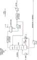
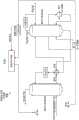
图1A示出了原油精炼设备中的芳烃联合装置二甲苯产物分离单元420。提余液塔塔顶产物流股可以作为单一流股在装置中流动并且分裂成多个流股,或者其可以作为多个流股流动到装置中。在一些实施方式中,如图1A中所示,提余液塔顶产物流股分离成三个流股以有利于热回收。第一提余液塔塔顶产物流股在具有可以为约15MW至25MW(例如,21MW)的热负荷的第一热交换器中直接加热胺再生器塔底流股。第二提余液塔塔顶产物流股在具有可以为约1MW至10MW(例如,6MW)的热负荷的第二热交换器中直接加热苯塔塔底流股。第三提余液塔塔顶产物流股在具有可以为约5MW至15MW(例如,8.6MW)的热负荷的第三热交换器中直接加热提余液分割塔塔底流股。以此方式,相对于提余液塔塔顶流股的流动,第一热交换器、第二热交换器和第三热交换器彼此并联地连接(耦接,couple)。对于各个提余液塔塔顶产物流股,热量直接至另一过程流股的转移捕获否则将被排出到环境中的热量。将提余液塔顶产物流股重新合并并且返回到二甲苯产物分离单元420用于进一步加工。Figure 1A shows an aromatics complex xylene
图1B示出了原油精炼设备中的硫回收装置402。经加热的胺再生器塔底流股流动到硫回收装置402。如图1B中所示,用于胺再生器的蒸汽热输入可以是0MW,因为在此配置中公开的备选流动路径(流程,flow path)可以满足用于该塔的操作(运行,operation)的整个热负荷。在一个备选实施方案中,可以减少用于硫回收装置胺再生器的蒸汽热输入,因为在此配置中公开的备选流动路径可以部分地满足用于该塔的操作的热负荷。Figure IB shows
图1C示出了原油精炼设备中的苯提取单元418。经加热的苯塔塔底流股流动到苯提取单元418。如图1C中所示,用于苯塔的蒸汽热输入可以是0MW,因为在此配置中公开的备选流动路径可以满足用于该塔的操作的整个热负荷。在一个备选实施方案中,可以减少用于苯塔的蒸汽热输入,因为在此配置中公开的备选流动路径可以部分地满足用于该塔的操作的热负荷。Figure 1C shows a
图1D也示出了原油精炼设备中的苯提取单元418。经加热的提余液分割塔塔底流股然后流动到苯提取单元418。如图1D中所示,用于提余液分割塔的蒸汽热输入可以是0MW,因为在此配置中公开的备选流动路径可以满足用于该塔的操作的整个热负荷。在一个备选实施方案中,可以减少用于提余液分割塔的蒸汽热输入,因为在此配置中公开的备选流动路径可以部分地满足用于该塔的操作的热负荷。Figure ID also shows the
以此方式,芳烃联合装置二甲苯产物分离单元使用回收的废热直接加热硫回收装置和芳烃联合装置苯提取单元两者,节省约36MW的热能。In this way, the aromatics complex xylene product separation unit uses the recovered waste heat to directly heat both the sulfur recovery unit and the aromatics complex benzene extraction unit, saving approximately 36 MW of thermal energy.
配置1–方案B
如图1E-1H中所示,在一些实施方式中,可以使用在单一第二装置中的第二流股间接地加热在多个第一装置中的多个第一流股。在一些实施方式中,多个第一装置可以包括硫回收装置和芳烃联合装置苯提取单元,并且第二流股可以包括胺再生器塔底产物、苯塔塔底产物和提余液分割塔塔底产物流股。第二装置可以包括芳烃联合装置二甲苯产物分离单元,并且第二装置流股可以包括提余液塔塔顶产物流股。As shown in Figures 1E-1H, in some embodiments, multiple first streams in multiple first devices can be indirectly heated using the second stream in a single second device. In some embodiments, the plurality of first units can include a sulfur recovery unit and an aromatics complex benzene extraction unit, and the second stream can include amine regenerator bottoms, benzene column bottoms, and raffinate split columns Bottom product stream. The second unit may include an aromatics complex xylene product separation unit, and the second unit stream may include a raffinate column overhead product stream.
所描述且在图1E-1H中示出的热整合可以减少原油精炼设备的能量消耗(例如,加热和冷却公用工程)。例如,约36MW的能量消耗减少可以转换为原油精炼设备中约6%的能量消耗。如之后描述的,过程流股之间的热交换可以使用中间缓冲流体,例如,水、油或其他缓冲流体实施。The thermal integration described and shown in FIGS. 1E-1H can reduce energy consumption (eg, heating and cooling utilities) of crude oil refinery facilities. For example, a reduction in energy consumption of about 36 MW can translate to about 6% of the energy consumption in a crude oil refining facility. As described later, heat exchange between process streams can be performed using an intermediate buffer fluid, eg, water, oil, or other buffer fluid.
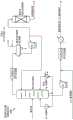
间接加热流股可以包括通过缓冲流体,例如,油、水或其他缓冲流体加热流股。来自缓冲流体罐(例如,热水罐)的缓冲流体(例如,高压水)流动到芳烃联合装置二甲苯产物分离单元420,如图1E中所示。缓冲流体可以作为单一流股流入到装置中并且分裂成多个流股,或者其可以作为多个流股流入到装置中。Indirectly heating the stream may include heating the stream through a buffer fluid, eg, oil, water, or other buffer fluid. Buffer fluid (eg, high pressure water) from a buffer fluid tank (eg, hot water tank) flows to aromatics complex xylene
图1E示出了芳烃联合装置二甲苯产物分离单元420。在一些实施方式中,来自缓冲流体收集罐的缓冲流体流动到芳烃装置二甲苯产物分离单元420。提余液塔塔顶产物流股在具有可以为约30MW至40MW(例如,36MW)的热负荷的第一热交换器中加热缓冲流体。热量从过程流股到缓冲流体中的转移捕获否则将被排出到环境中的热量。将提余液塔塔顶产物流股返回到二甲苯产物分离单元420用于进一步加工。Figure IE shows aromatics complex xylene
经加热的缓冲流体流动到经加热的缓冲流体收集集管(collection header)。来自收集集管(或在一些实施方案中,可以将经加热的所收集缓冲流体在使用前保持一段时间的经加热或绝热的缓冲流体罐或储存单元)的经加热的缓冲流体可以流动到硫回收装置402或苯提取单元418。如图1E中所示,经加热的缓冲流体以三个支流分布至硫回收装置402和苯提取单元418两者。The heated buffer fluid flows to a heated buffer fluid collection header. Heated buffer fluid from a collection header (or in some embodiments, a heated or insulated buffer fluid tank or storage unit that can hold the heated collected buffer fluid for a period of time before use) can flow to the
图1F示出了原油精炼设备中的硫回收装置402。第一经加热的缓冲流体流股流动到硫回收装置402。第一经加热的缓冲流体流股在具有可以为约15MW至25MW(例如,21MW)的热负荷的第二热交换器中加热胺再生器塔底流股。相对于经加热的缓冲流体的流动,第二热交换器与第一热交换器串联地连接并且在第一热交换器的下游。如图1F中所示,用于胺再生器的蒸汽热输入可以是0MW,因为在此配置中公开的备选流动路径可以满足用于该塔的操作的整个热负荷。在一个备选实施方案中,可以减少用于胺再生器的蒸汽热输入,因为在此配置中公开的备选流动路径可以部分地满足用于该塔的操作的热负荷。FIG. 1F shows
图1G示出了原油精炼设备中的苯提取单元418。第二经加热的缓冲流体流动到芳烃联合装置苯提取单元418。第二经加热的缓冲流体流股在具有可以为约1MW至10MW(例如,6MW)的热负荷的第三热交换器中加热苯塔塔底流股。相对于经加热的缓冲流体的流动,第三热交换器与第一热交换器串联地连接并且在第一热交换器的下游。如图1G中所示,用于苯塔的蒸汽热输入可以是0MW,因为在此配置中公开的备选流动路径可以满足用于该塔的操作的整个热负荷。在一个备选实施方案中,可以减少用于苯塔的蒸汽热输入,因为在此配置中公开的备选流动路径可以部分地满足用于该塔的操作的热负荷。Figure 1G shows a
图1G示出了原油精炼设备中的苯提取单元418。第三经加热的缓冲流体流动到芳烃联合装置苯提取单元418。第三经加热的缓冲流体流股在具有可以为约5MW至15MW(例如,8.6MW)的热负荷的第四热交换器中加热提余液分流器塔塔底流股。相对于经加热的缓冲流体的流动,第四热交换器与第一热交换器串联地连接并且在第一热交换器的下游。如图1H中所示,用于苯塔的蒸汽热输入可以是0MW,因为在此配置中公开的备选流动路径可以满足用于该塔的操作的整个热负荷。在一个备选实施方案中,可以减少用于苯塔的蒸汽热输入,因为在此配置中公开的备选流动路径可以部分地满足用于该塔的操作的热负荷。Figure 1G shows a
离开第二热交换器、第三热交换器和第四热交换器的经加热的缓冲流体各自流动到收集集管或缓冲液体罐。以此方式,第二热交换器、第三热交换器和第四热交换器相对于经加热的缓冲流体的流动彼此并联地流体连接。The heated buffer fluid exiting the second, third, and fourth heat exchangers each flows to a collection header or a buffer liquid tank. In this way, the second heat exchanger, the third heat exchanger and the fourth heat exchanger are fluidly connected in parallel with each other with respect to the flow of the heated buffer fluid.
图1E-1H示出了这样的间接来自第一芳烃联合装置子单元的废热的回收和再利用可以导致减少或消除用于加热在硫回收装置和第二芳烃联合装置子单元两者中的流股的热能需求如约36MW。Figures 1E-1H illustrate that such recovery and reuse of waste heat indirectly from the first aromatics complex subunit can result in a reduction or elimination of streams used to heat both the sulfur recovery unit and the second aromatics complex subunit The thermal energy demand of the unit is about 36MW.
配置2
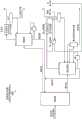
图1I-1P举例说明了用于将原油精炼设备中的芳烃装置子单元与其他芳烃联合装置子单元和酸性污水汽提塔装置热整合的配置和相关方案细节。在某些方案中,过程流股(例如,来自芳烃装置的一个精炼子单元的流股或其他过程流股)可以用于直接加热另一过程流股(例如,来自芳烃装置的另一精炼子单元的另一流股或其他过程流股)。在某些配置中,过程流股之间的热交换可以使用中间缓冲流体,例如,水、油或其他缓冲流体实施。Figures 1I-1P illustrate configurations and associated scheme details for thermally integrating an aromatics unit subunit in a crude oil refinery with other aromatics complex unit subunits and a sour sewage stripper unit. In some aspects, a process stream (eg, a stream from one refinery subunit of an aromatics unit or other process stream) may be used to directly heat another process stream (eg, from another refining subunit of an aromatics unit) another stream of the unit or another process stream). In certain configurations, heat exchange between process streams may be performed using an intermediate buffer fluid, eg, water, oil, or other buffer fluid.
配置2–方案A
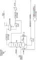
如图1I-1L中所示,热整合原油精炼设备中的不同精炼装置。在这些配置中描述且在图1I-1L中示出的热整合可以减少原油精炼设备的能量消耗(例如,加热和冷却公用工程)。例如,约47MW的能量消耗减少可以转换为原油精炼设备中约7%的能量消耗。如之后描述的,在某些方案中,过程流股(例如,芳烃联合装置二甲苯产物单元流股或其他过程流股)可以用于直接加热另一过程流股(例如,酸性污水汽提塔装置流股或其他过程流股)。As shown in Figures 1I-1L, the different refining units in a crude oil refining facility are thermally integrated. The thermal integration described in these configurations and shown in FIGS. 1I-1L can reduce crude oil refinery energy consumption (eg, heating and cooling utilities). For example, a reduction in energy consumption of about 47 MW can translate to about 7% of the energy consumption in crude oil refining facilities. As described later, in certain scenarios, a process stream (eg, aromatics complex xylene product unit stream or other process stream) may be used to directly heat another process stream (eg, sour sewage stripper) equipment streams or other process streams).
在一些实施方式中,可以使用在单一第二装置中的第二流股直接加热在多个第一装置中的多个第一流股。在一些实施方式中,多个第一装置可以包括酸性污水汽提塔装置和芳烃联合装置苯提取单元,并且多个第一流股可以包括酸性污水汽提塔再生器塔底产物、苯塔塔底产物和提余液分流器塔底产物流股。第二装置可以包括芳烃联合装置二甲苯产物分离单元,并且第二流股可以包括提余液塔塔顶产物流股。In some embodiments, multiple first streams in multiple first devices may be directly heated using the second stream in a single second device. In some embodiments, the plurality of first units can include a sour sewage stripper unit and an aromatics complex benzene extraction unit, and the plurality of first streams can include a sour sewage stripper regenerator bottoms, benzene column bottoms Product and raffinate splitter bottoms streams. The second unit can include an aromatics complex xylene product separation unit, and the second stream can include a raffinate column overhead product stream.
图1I示出了原油精炼设备中的芳烃联合装置二甲苯产物分离单元420。提余液塔塔顶产物流股可以作为单一流股在装置中流动并且分离成多个流股,或者其可以作为多个流股流入到装置中。在一些实施方式中,如图1I中所示,提余液塔塔顶流股分成三个流股以有利于热回收。第一提余液塔顶产物流股在具有可以为约25MW至35MW(例如,32MW)的热负荷的第一热交换器中直接加热酸性污水汽提塔塔底流股。第二提余液塔塔顶产物流股在具有可以为约1MW至10MW(例如,6MW)的热负荷的第二热交换器中直接加热苯塔塔底流股。第三提余液塔塔顶产物流股在具有可以为约5MW至15MW(例如,8.6MW)的热负荷的第三热交换器中直接加热提余液分割塔塔底流股。以此方式,相对于提余液塔塔顶产物的流动,第一热交换器、第二热交换器和第三热交换器彼此并联地连接。对于各个提余液塔塔顶产物流股,热量直接至另一过程流股的转移捕获否则将被排出到环境中的热量。将提余液塔顶流股重新合并并且返回到二甲苯产物分离单元420用于进一步加工。Figure II shows the aromatics complex xylene
图1J示出了原油精炼设备中的酸性污水汽提塔装置410。经加热的酸性污水汽提塔塔底流股流动到酸性污水汽提塔装置410。如图1J中所示,用于酸性污水汽提塔的蒸汽热输入可以是0MW,因为在此配置中公开的备选流动路径可以满足用于该塔的操作的整个热负荷。在一个备选实施方案中,可以减少用于酸性污水汽提塔的蒸汽热输入,因为在此配置中公开的备选流动路径可以部分地满足用于该塔的操作的热负荷。Figure 1J shows the sour
图1K示出了原油精炼设备中的苯提取单元418。经加热的苯塔塔底流股流动到苯提取单元418。如图1K中所示,用于苯塔的蒸汽热输入可以是0MW,因为在此配置中公开的备选流动路径可以满足用于该塔的操作的整个热负荷。在一个备选实施方案中,可以减少用于苯塔的蒸汽热输入,因为在此配置中公开的备选流动路径可以部分地满足用于该塔的操作的热负荷。Figure 1K shows the
图1L也示出了原油精炼设备中的苯提取单元418。经加热的提余液分割塔塔底流股流动到苯提取单元418。如图1L中所示,用于提余液分割塔的蒸汽热输入可以是0MW,因为在此配置中公开的备选流动路径可以满足用于该塔的操作的整个热负荷。在一个备选实施方案中,可以减少用于提余液分割塔的蒸汽热输入,因为在此配置中公开的备选流动路径可以部分地满足用于该塔的操作的热负荷。Figure 1L also shows the
以此方式,芳烃联合装置二甲苯产物分离单元使用回收的废热直接加热酸性污水汽提塔装置和芳烃联合装置苯提取单元两者,节省约47MW的热能。In this way, the aromatics complex xylene product separation unit uses the recovered waste heat to directly heat both the sour sewage stripper unit and the aromatics complex benzene extraction unit, saving approximately 47 MW of thermal energy.
配置2–方案B
如图1M-1P中所示,在一些实施方式中,可以使用在单一第二装置中的第二流股间接加热在多个第一装置中的多个第一流股。在一些实施方式中,多个第一装置可以包括酸性污水汽提塔装置和芳烃联合装置苯提取单元,并且多个第一流股包括酸性污水汽提塔再生器塔底产物、苯塔塔底产物和提余液分流器塔底产物流股。第二装置可以包括芳烃联合装置二甲苯产物分离单元,并且第二流股可以包括提余液塔塔顶产物流股。As shown in Figures 1M-1P, in some embodiments, multiple first streams in a plurality of first devices may be indirectly heated using a second stream in a single second device. In some embodiments, the plurality of first units can include a sour sewage stripper unit and an aromatics complex benzene extraction unit, and the plurality of first streams include a sour sewage stripper regenerator bottoms, benzene column bottoms and raffinate splitter bottoms stream. The second unit can include an aromatics complex xylene product separation unit, and the second stream can include a raffinate column overhead product stream.
所描述且在图1M-1P中示出的热整合可以减少原油精炼设备的能量消耗(例如,加热和冷却公用工程)。例如,约47MW,例如46.6MW的能量消耗减少可以转换为原油精炼设备中约7%的能量消耗。如之后描述的,过程流股之间的热交换可以使用中间缓冲流体,例如,水、油或其他缓冲流体实施。The thermal integration described and shown in FIGS. 1M-1P can reduce energy consumption (eg, heating and cooling utilities) of crude oil refinery facilities. For example, a reduction in energy consumption of about 47 MW, eg, 46.6 MW, can translate into about 7% of the energy consumption in a crude oil refining facility. As described later, heat exchange between process streams can be performed using an intermediate buffer fluid, eg, water, oil, or other buffer fluid.
间接加热流股可以包括经由缓冲流体,例如,油、水或其他缓冲流体加热流股。来自缓冲流体罐(例如,热水罐)的缓冲流体(例如,高压水)流动到芳烃联合装置二甲苯产物分离单元420,如图1M中所示。缓冲流体可以作为单一流股流入到装置中并且分裂成多个流股,或者其可以作为多个流股流入到装置中。Indirectly heating the stream may include heating the stream via a buffer fluid, eg, oil, water, or other buffer fluid. Buffer fluid (eg, high pressure water) from a buffer fluid tank (eg, a hot water tank) flows to aromatics complex xylene
图1M示出芳烃联合装置二甲苯产物分离单元420。在一些实施方式中,来自缓冲流体收集罐的缓冲流体流动到芳烃装置二甲苯产物分离单元420。提余液塔塔顶产物流股在具有可以为约40MW至50MW(例如,47MW)的热负荷的第一热交换器中加热缓冲流体。热量从过程流股到缓冲流体中的转移捕获否则将被排出到环境中的热量。将提余液塔塔顶产物流股返回到二甲苯产物分离单元420用于进一步加工。Figure 1M shows aromatics complex xylene
经加热的缓冲流体流动到经加热的缓冲流体收集集管。来自收集集管(或在一些实施方案中,可以将经加热的所收集缓冲流体在使用前保持一段时间的经加热或绝热的缓冲流体罐或储存单元)的经加热的缓冲流体可以流动到酸性污水汽提塔装置410或苯提取单元418。The heated buffer fluid flows to the heated buffer fluid collection header. The heated buffer fluid from the collection header (or in some embodiments, a heated or insulated buffer fluid tank or storage unit that can hold the heated collected buffer fluid for a period of time prior to use) can flow to an acidic
在此情形中,离开第一热交换器的经加热的缓冲流体流动到苯提取单元418。图1N示出了原油精炼设备中的芳烃联合装置苯提取单元420。经加热的缓冲流体在具有可以为约1MW至10MW(例如,6MW)的热负荷的第三热交换器中加热苯塔塔底流股。相对于经加热的缓冲流体的流动,第三热交换器与第一热交换器串联地连接并且在第一热交换器的下游。如图1N中所示,用于苯塔的蒸汽热输入可以是0MW,因为在此配置中公开的备选流动路径可以满足用于该塔的操作的整个热负荷。在一个备选实施方案中,可以减少用于苯塔的蒸汽热输入,因为在此配置中公开的备选流动路径可以部分地满足用于该塔的操作的热负荷。In this case, the heated buffer fluid exiting the first heat exchanger flows to the
离开第三热交换器的经加热的缓冲流体被分裂成两个经加热的缓冲流体流股。图1O示出了原油精炼设备中的酸性污水汽提塔装置410。第一经加热的缓冲流体流股流动到酸性污水汽提塔装置410。第一经加热的缓冲流体流股在具有可以为约15MW至25MW(例如,21MW)的热负荷的第二热交换器中加热酸性污水汽提塔塔底流股。相对于经加热的缓冲流体的流动,第二热交换器与第一热交换器串联地连接并且在第一热交换器的下游。如图1O中所示,用于酸性污水汽提塔的蒸汽热输入可以是0MW,因为在此配置中公开的备选流动路径可以满足用于该塔的操作的整个热负荷。在一个备选实施方案中,可以减少用于酸性污水汽提塔的蒸汽热输入,因为在此配置中公开的备选流动路径可以部分地满足用于该塔的操作的热负荷。The heated buffer fluid exiting the third heat exchanger is split into two heated buffer fluid streams. Figure 10 shows the sour
图1P也示出了原油精炼设备中的芳烃联合装置苯提取单元420。第二经加热的缓冲流体流动到芳烃联合装置苯提取单元418。第二经加热的缓冲流体流股在具有可以为约5MW至15MW(例如,8.6MW)的热负荷的第四热交换器中加热提余液分割塔塔底流股。相对于经加热的缓冲流体的流动,第四热交换器与第一热交换器串联地连接并且在第一热交换器的下游。如图1P中所示,用于提余液分流器的蒸汽热输入可以是0MW,因为在此配置中公开的备选流动路径可以满足用于该塔的操作的整个热负荷。在一个备选实施方案中,可以减少用于提余液分流器的蒸汽热输入,因为在此配置中公开的备选流动路径可以部分地满足用于该塔的操作的热负荷。Figure 1P also shows the aromatics complex
离开第二热交换器和第四热交换器的经加热的缓冲流体支流各自流动到收集集管或缓冲液体罐。以此方式,第二热交换器和第四热交换器相对于经加热的缓冲流体的流动彼此并联地流体连接。The heated buffer fluid substreams exiting the second and fourth heat exchangers each flow to a collection header or buffer liquid tank. In this way, the second heat exchanger and the fourth heat exchanger are fluidly connected in parallel with each other with respect to the flow of the heated buffer fluid.
在一些实施方式中,合并的经加热的缓冲流体可以按顺序流过不同的装置。例如,合并的经加热的缓冲流体首先流过苯提取单元和硫回收装置的组合,然后合并以流过苯提取单元。以该顺序离开最后的一个或多个热交换器的经加热的缓冲流体然后可以流动到缓冲流体罐。来自缓冲流体罐的缓冲流体然后可以流动到不同的装置以重新开始废热回收和再利用循环。In some embodiments, the combined heated buffer fluid may flow through different devices sequentially. For example, the combined heated buffer fluid first flows through the combination of the benzene extraction unit and sulfur recovery unit, and then is combined to flow through the benzene extraction unit. The heated buffer fluid exiting the last heat exchanger or heat exchangers in this order may then flow to a buffer fluid tank. The buffer fluid from the buffer fluid tank can then flow to a different device to restart the waste heat recovery and reuse cycle.
图1M-1P示出了这样的间接来自第一芳烃联合装置子单元的废热的回收和再利用可以导致减少或消除用于加热酸性污水汽提塔装置和第二芳烃联合装置子单元两者中的流股的热能需求如约47MW。Figures 1M-1P illustrate that such indirect recovery and reuse of waste heat from the first aromatics complex subunit can result in a reduction or elimination of heat used in both the sour sewage stripper unit and the second aromatics complex subunit. The thermal energy demand of the stream is about 47MW.
配置3
图1QA-1RB举例说明了用于将原油精炼厂中的精炼芳烃联合装置子单元与其他芳烃联合装置子单元和胺再生装置热整合的配置和相关方案细节。在某些方案中,过程流股(例如,酸性气体回收装置流股或其他过程流股)可以用于直接加热另一过程流股(例如,芳烃装置流股或其他过程流股)。在某些配置中,过程流股之间的热交换可以使用中间缓冲流体,例如,水、油或其他缓冲流体实施。Figures 1QA-1RB illustrate configurations and associated scheme details for thermally integrating a refining aromatics complex subunit with other aromatics complex subunits and an amine regeneration unit in a crude oil refinery. In some aspects, a process stream (eg, an acid gas recovery unit stream or other process stream) may be used to directly heat another process stream (eg, an aromatics unit stream or other process stream). In certain configurations, heat exchange between process streams may be performed using an intermediate buffer fluid, eg, water, oil, or other buffer fluid.
配置3–方案A
图1Q(由图1QA和1QB组成)示出了用于热整合原油精炼设备中的不同精炼装置的配置和相关方案细节。在这些配置中描述且在图1Q中示出的热整合可以减少原油精炼设备的能量消耗(例如,加热和冷却公用工程)。例如,约48MW(例如,47.8MW)的能量消耗减少,其可以转换为原油精炼设备中至少约7%的能量消耗。如之后描述的,在某些方案中,过程流股(例如,芳烃联合装置二甲苯产物单元流股或其他过程流股)可以用于直接加热另一过程流股(例如,酸性气体再生器或其他过程流股)。Figure 1Q (consisting of Figures 1QA and 1QB) shows the configuration and associated scheme details for different refiners in a thermally integrated crude oil refinery. The thermal integration described in these configurations and shown in FIG. 1Q can reduce crude oil refinery energy consumption (eg, heating and cooling utilities). For example, about 48 MW (eg, 47.8 MW) of energy consumption is reduced, which can translate into at least about 7% of the energy consumption in the crude oil refinery. As described later, in certain scenarios, a process stream (eg, aromatics complex xylene product unit stream or other process stream) may be used to directly heat another process stream (eg, acid gas regenerator or other process streams).
在一些实施方式中,可以使用在单一第二装置中的第二流股直接加热在第一装置中的第一流股。在一些实施方式中,第一装置可以包括胺再生装置,并且第一流股是酸性气体再生器塔底流股。第二装置可以包括芳烃联合装置二甲苯产物分离单元,并且第二流股可以包括提余液塔塔顶产物流股。In some embodiments, the second stream in a single second device can be used to directly heat the first stream in the first device. In some embodiments, the first unit may comprise an amine regeneration unit, and the first stream is an acid gas regenerator bottoms stream. The second unit can include an aromatics complex xylene product separation unit, and the second stream can include a raffinate column overhead product stream.
图1QA示出了原油精炼设备中的芳烃联合装置二甲苯产物分离单元420。提余液塔顶流股在具有可以为约45MW至55MW(例如,47.8MW)的热负荷的第一热交换器中直接加热酸性气体再生器塔底流股。热量直接至另一过程流股的转移捕获否则将被排出到环境中的热量。将提余液塔顶流股返回到二甲苯产物分离单元420用于进一步加工。Figure 1QA shows an aromatics complex xylene
图1QB示出了原油精炼设备中的胺再生装置406。经加热的酸性气体再生器塔底流股流动到胺再生装置406。如图1QB中所示,用于酸性气体再生器的蒸汽热输入可以是0MW,因为在此配置中公开的备选流动路径可以满足用于该塔的操作的整个热负荷。在一个备选实施方案中,可以减少用于酸性气体再生器的蒸汽热输入,因为在此配置中公开的备选流动路径可以部分地满足用于该塔的操作的热负荷。Figure 1QB shows an
以此方式,芳烃联合装置二甲苯产物分离单元使用回收的废热直接加热胺再生装置,节省约48MW的热能。In this way, the aromatics complex xylene product separation unit uses the recovered waste heat to directly heat the amine regeneration unit, saving approximately 48 MW of thermal energy.
配置3–方案B
如图1R(由图1RA和1RB组成)中所示,在一些实施方式中,可以使用在单一第二装置中的第二流股间接加热在单一第一装置中的第一流股。在一些实施方式中,第一装置可以包括胺再生装置,并且第一流股是酸性气体再生器塔底流股。第二装置可以包括芳烃联合装置二甲苯产物分离单元,并且第二流股可以包括提余液塔塔顶产物流股。As shown in Figure 1R (consisting of Figures 1RA and 1RB), in some embodiments, the first stream in the single first device may be indirectly heated using the second stream in the single second device. In some embodiments, the first unit may comprise an amine regeneration unit, and the first stream is an acid gas regenerator bottoms stream. The second unit can include an aromatics complex xylene product separation unit, and the second stream can include a raffinate column overhead product stream.
在这些配置中描述且在图1R中示出的热整合可以减少原油精炼设备的能量消耗(例如,加热和冷却公用工程)。例如,约48MW(例如,47.8MW)的能量消耗减少可以转换为原油精炼设备中至少约7%的能量消耗。如之后描述的,过程流股之间的热交换可以使用中间缓冲流体,例如,水、油或其他缓冲流体实施。The thermal integration described in these configurations and shown in FIG. 1R can reduce the energy consumption (eg, heating and cooling utilities) of the crude oil refinery. For example, a reduction in energy consumption of about 48 MW (eg, 47.8 MW) may translate to at least about 7% of the energy consumption in the crude oil refining facility. As described later, heat exchange between process streams can be performed using an intermediate buffer fluid, eg, water, oil, or other buffer fluid.
间接加热流股可以包括经由缓冲流体,例如,油、水或其他缓冲流体加热流股。来自缓冲流体罐(例如,热水罐)的缓冲流体(例如,高压水)流动到芳烃联合装置二甲苯产物分离单元420,如图1R中所示。缓冲流体可以作为单一流股流入到装置中并且分裂成多个流股,或者其可以作为多个流股流入到装置中。Indirectly heating the stream may include heating the stream via a buffer fluid, eg, oil, water, or other buffer fluid. Buffer fluid (eg, high pressure water) from a buffer fluid tank (eg, a hot water tank) flows to aromatics complex xylene
图1RA示出了芳烃联合装置二甲苯产物分离单元420。来自缓冲流体收集罐(如图1RB中所示)的缓冲流体流动到芳烃装置二甲苯产物分离单元420(如图1RA中所示)。提余液塔塔顶产物流股在具有可以为约45MW至55MW(例如,47.8MW)的热负荷的第一热交换器中加热缓冲流体。热量从过程流股到缓冲流体中的转移捕获否则将被排出到环境中的热量。将提余液塔塔顶产物流股返回到二甲苯产物分离单元420用于进一步加工。Figure 1RA shows the aromatics complex xylene
经加热的缓冲流体流动到经加热的缓冲流体收集集管。离开第一热交换器的来自收集集管(或在一些实施方案中,可以将经加热的所收集缓冲流体在使用前保持一段时间的经加热或绝热的缓冲流体罐或储存单元)的经加热的缓冲流体流动到胺再生装置406。The heated buffer fluid flows to the heated buffer fluid collection header. Heated heat from the collection header (or in some embodiments, a heated or insulated buffer fluid tank or storage unit that may hold the heated collected buffer fluid for a period of time before use) leaving the first heat exchanger The buffer fluid flows to the
图1RB示出了原油精炼设备中的胺再生装置406。流动到胺再生装置406的经加热的缓冲流体在具有可以为约45MW至55MW(例如,47.8MW)的热负荷的第二热交换器中加热酸性气体再生器塔底流股。相对于缓冲流体的流动,第一热交换器和第二热交换器与第一热交换器连接并且在第一热交换器的下游。如图1RB中所示,用于酸性气体再生器的蒸汽热输入可以是0MW,因为在此配置中公开的备选流动路径可以满足用于该塔的操作的整个热负荷。在一个备选实施方案中,可以减少用于酸性气体再生器的蒸汽热输入,因为在此配置中公开的备选流动路径可以部分地满足用于该塔的操作的热负荷。Figure 1RB shows an
离开第二热交换器的缓冲流体流回到缓冲流体罐或收集集管,在那里缓冲流体可以再利用并重复加热循环。The buffer fluid exiting the second heat exchanger flows back to the buffer fluid tank or collection header, where the buffer fluid can be reused and the heating cycle repeated.
图1RA-1RB示出了这样的间接来自芳烃联合装置子单元的废热的回收和再利用可以导致减少或消除用于加热胺再生装置中的流股的热能需求如约48MW。Figures 1RA-1RB show that such recovery and reuse of waste heat indirectly from aromatics complex subunits can result in a reduction or elimination of thermal energy requirements, eg, about 48 MW, for heating the stream in the amine regeneration unit.
总之,本公开内容描述了用于综合精炼-石化设备中的热能消耗减少的动力装置内废热回收方案和装置热连接的配置和相关加工方案,其整合用于草根中级原油半转化精炼厂以提高来自低级废热源的特定部分的能量效率。本公开内容还描述了用于综合精炼-石化设备中的热能消耗减少的特定装置内废热回收方案和装置热连接的配置和相关加工方案,其整合用于综合中级原油半转化精炼厂和芳烃联合装置以提高来自低级废物源的特定部分的能量效率。In summary, the present disclosure describes an in-power plant waste heat recovery scheme and plant thermal connection configuration and associated processing scheme for thermal energy consumption reduction in an integrated refinery-petrochemical facility integrated for a grassroots intermediate crude oil semi-conversion refinery to improve The energy efficiency of a specific portion from a low-grade waste heat source. The present disclosure also describes specific in-unit waste heat recovery schemes and plant thermal connection configurations and associated processing schemes for thermal energy consumption reduction in an integrated refinery-petrochemical facility integrated for an integrated intermediate crude semi-conversion refinery and aromatics complex Devices to increase the energy efficiency of specific fractions from low-grade waste sources.
对于所有工业,工业生产的经济性、全球能量供应的局限性和环境保护的现实都是关注点。据信,世界环境已经受部分由GHG到大气中的释放造成的全球变暖负面影响。此处描述的主题的实施方式可以缓解这些问题中的一些,并且在一些情况下,防止在减少它们的GHG排放方面有困难的某些精炼厂不得不关闭。通过实施此处描述的技术,可以通过来自低级废热源的特定部分的回收和再利用使精炼厂中的特定装置或精炼厂作为整体更高效并且污染性更低。For all industries, the economics of industrial production, the limitations of the global energy supply and the realities of environmental protection are concerns. It is believed that the world environment is already negatively affected by global warming caused in part by the release of GHG into the atmosphere. Embodiments of the subject matter described herein may alleviate some of these problems and, in some cases, prevent certain refineries having difficulty reducing their GHG emissions from having to shut down. By implementing the techniques described herein, specific units in a refinery, or the refinery as a whole, can be made more efficient and less polluting through the recovery and reuse of specific portions from low-grade waste heat sources.
因此,已经描述了所述主题的特定实施方式。其他实施方式在所附权利要求的范围内。Accordingly, specific implementations of the subject matter have been described. Other implementations are within the scope of the appended claims.
Claims (21)
Applications Claiming Priority (9)
| Application Number | Priority Date | Filing Date | Title |
|---|---|---|---|
| US201562209147P | 2015-08-24 | 2015-08-24 | |
| US201562209188P | 2015-08-24 | 2015-08-24 | |
| US201562209223P | 2015-08-24 | 2015-08-24 | |
| US201562209217P | 2015-08-24 | 2015-08-24 | |
| US62/209,147 | 2015-08-24 | ||
| US62/209,217 | 2015-08-24 | ||
| US62/209,223 | 2015-08-24 | ||
| US62/209,188 | 2015-08-24 | ||
| PCT/US2016/048067WO2017035084A1 (en) | 2015-08-24 | 2016-08-22 | Recovery and re-use of waste energy in industrial facilities |
Publications (2)
| Publication Number | Publication Date |
|---|---|
| CN108138593A CN108138593A (en) | 2018-06-08 |
| CN108138593Btrue CN108138593B (en) | 2020-12-22 |
Family
ID=56843063
Family Applications (13)
| Application Number | Title | Priority Date | Filing Date |
|---|---|---|---|
| CN201680056304.7AExpired - Fee RelatedCN108026789B (en) | 2015-08-24 | 2016-08-22 | Recovery and reuse of waste energy in industrial equipment |
| CN201680060985.4AExpired - Fee RelatedCN108138590B (en) | 2015-08-24 | 2016-08-22 | Recovery and reuse of waste energy in industrial equipment |
| CN201680059774.9AExpired - Fee RelatedCN108138055B (en) | 2015-08-24 | 2016-08-22 | Recovery and reuse of waste energy in industrial equipment |
| CN201680060986.9AExpired - Fee RelatedCN108138594B (en) | 2015-08-24 | 2016-08-22 | Recovery and reuse of waste energy in industrial equipment |
| CN201680061070.5AExpired - Fee RelatedCN108138592B (en) | 2015-08-24 | 2016-08-22 | Recovery and reuse of waste energy in industrial equipment |
| CN202011466449.9APendingCN112745954A (en) | 2015-08-24 | 2016-08-22 | Recovery and reuse of waste energy in industrial plants |
| CN201680061004.8AExpired - Fee RelatedCN108138591B (en) | 2015-08-24 | 2016-08-22 | Recovery and reuse of waste energy in industrial plants |
| CN201680060979.9AExpired - Fee RelatedCN108138056B (en) | 2015-08-24 | 2016-08-22 | Recovery and reuse of waste energy in industrial equipment |
| CN201680056303.2AExpired - Fee RelatedCN108138593B (en) | 2015-08-24 | 2016-08-22 | Recovery and reuse of waste energy in industrial equipment |
| CN201680061739.0AActiveCN108350762B (en) | 2015-08-24 | 2016-08-23 | By the waste-heat power generation in comprehensive crude oil refining, aromatic hydrocarbons and public work equipment |
| CN201680061069.2AExpired - Fee RelatedCN108138605B (en) | 2015-08-24 | 2016-08-23 | Power generation from waste heat in integrated hydrocracking and diesel hydrotreating plants |
| CN201680061248.6AActiveCN108138606B (en) | 2015-08-24 | 2016-08-23 | Power generation from waste heat in integrated crude oil refining and aromatics plant using independent three organic rankine cycles |
| CN201680061260.7AExpired - Fee RelatedCN108138607B (en) | 2015-08-24 | 2016-08-23 | Power generation from waste heat in integrated crude oil refining and aromatics plants |
Family Applications Before (8)
| Application Number | Title | Priority Date | Filing Date |
|---|---|---|---|
| CN201680056304.7AExpired - Fee RelatedCN108026789B (en) | 2015-08-24 | 2016-08-22 | Recovery and reuse of waste energy in industrial equipment |
| CN201680060985.4AExpired - Fee RelatedCN108138590B (en) | 2015-08-24 | 2016-08-22 | Recovery and reuse of waste energy in industrial equipment |
| CN201680059774.9AExpired - Fee RelatedCN108138055B (en) | 2015-08-24 | 2016-08-22 | Recovery and reuse of waste energy in industrial equipment |
| CN201680060986.9AExpired - Fee RelatedCN108138594B (en) | 2015-08-24 | 2016-08-22 | Recovery and reuse of waste energy in industrial equipment |
| CN201680061070.5AExpired - Fee RelatedCN108138592B (en) | 2015-08-24 | 2016-08-22 | Recovery and reuse of waste energy in industrial equipment |
| CN202011466449.9APendingCN112745954A (en) | 2015-08-24 | 2016-08-22 | Recovery and reuse of waste energy in industrial plants |
| CN201680061004.8AExpired - Fee RelatedCN108138591B (en) | 2015-08-24 | 2016-08-22 | Recovery and reuse of waste energy in industrial plants |
| CN201680060979.9AExpired - Fee RelatedCN108138056B (en) | 2015-08-24 | 2016-08-22 | Recovery and reuse of waste energy in industrial equipment |
Family Applications After (4)
| Application Number | Title | Priority Date | Filing Date |
|---|---|---|---|
| CN201680061739.0AActiveCN108350762B (en) | 2015-08-24 | 2016-08-23 | By the waste-heat power generation in comprehensive crude oil refining, aromatic hydrocarbons and public work equipment |
| CN201680061069.2AExpired - Fee RelatedCN108138605B (en) | 2015-08-24 | 2016-08-23 | Power generation from waste heat in integrated hydrocracking and diesel hydrotreating plants |
| CN201680061248.6AActiveCN108138606B (en) | 2015-08-24 | 2016-08-23 | Power generation from waste heat in integrated crude oil refining and aromatics plant using independent three organic rankine cycles |
| CN201680061260.7AExpired - Fee RelatedCN108138607B (en) | 2015-08-24 | 2016-08-23 | Power generation from waste heat in integrated crude oil refining and aromatics plants |
Country Status (6)
| Country | Link |
|---|---|
| US (21) | US9803509B2 (en) |
| EP (14) | EP3341456A1 (en) |
| JP (12) | JP2018535280A (en) |
| CN (13) | CN108026789B (en) |
| SA (5) | SA518390985B1 (en) |
| WO (12) | WO2017035081A1 (en) |
Families Citing this family (50)
| Publication number | Priority date | Publication date | Assignee | Title |
|---|---|---|---|---|
| US9803507B2 (en)* | 2015-08-24 | 2017-10-31 | Saudi Arabian Oil Company | Power generation using independent dual organic Rankine cycles from waste heat systems in diesel hydrotreating-hydrocracking and continuous-catalytic-cracking-aromatics facilities |
| US9803508B2 (en) | 2015-08-24 | 2017-10-31 | Saudi Arabian Oil Company | Power generation from waste heat in integrated crude oil diesel hydrotreating and aromatics facilities |
| US9803506B2 (en) | 2015-08-24 | 2017-10-31 | Saudi Arabian Oil Company | Power generation from waste heat in integrated crude oil hydrocracking and aromatics facilities |
| US9803511B2 (en) | 2015-08-24 | 2017-10-31 | Saudi Arabian Oil Company | Power generation using independent dual organic rankine cycles from waste heat systems in diesel hydrotreating-hydrocracking and atmospheric distillation-naphtha hydrotreating-aromatics facilities |
| US9803509B2 (en)* | 2015-08-24 | 2017-10-31 | Saudi Arabian Oil Company | Power generation from waste heat in integrated crude oil refining and aromatics facilities |
| US9803513B2 (en) | 2015-08-24 | 2017-10-31 | Saudi Arabian Oil Company | Power generation from waste heat in integrated aromatics, crude distillation, and naphtha block facilities |
| US9803505B2 (en) | 2015-08-24 | 2017-10-31 | Saudi Arabian Oil Company | Power generation from waste heat in integrated aromatics and naphtha block facilities |
| US10626756B2 (en) | 2017-08-08 | 2020-04-21 | Saudi Arabian Oil Company | Natural gas liquid fractionation plant waste heat conversion to power using dual turbines organic Rankine cycle |
| US10480355B2 (en) | 2017-08-08 | 2019-11-19 | Saudi Arabian Oil Company | Natural gas liquid fractionation plant waste heat conversion to simultaneous power, cooling and potable water using modified goswami cycle and new modified multi-effect-distillation system |
| US10677104B2 (en) | 2017-08-08 | 2020-06-09 | Saudi Arabian Oil Company | Natural gas liquid fractionation plant waste heat conversion to simultaneous power, cooling and potable water using integrated mono-refrigerant triple cycle and modified multi-effect-distillation system |
| US10487699B2 (en) | 2017-08-08 | 2019-11-26 | Saudi Arabian Oil Company | Natural gas liquid fractionation plant waste heat conversion to cooling capacity using kalina cycle |
| US10436077B2 (en) | 2017-08-08 | 2019-10-08 | Saudi Arabian Oil Company | Natural gas liquid fractionation plant waste heat conversion to potable water using modified multi-effect distillation system |
| US10662824B2 (en) | 2017-08-08 | 2020-05-26 | Saudi Arabian Oil Company | Natural gas liquid fractionation plant waste heat conversion to power using organic Rankine cycle |
| US10443453B2 (en) | 2017-08-08 | 2019-10-15 | Saudi Araabian Oil Company | Natural gas liquid fractionation plant cooling capacity and potable water generation using integrated vapor compression-ejector cycle and modified multi-effect distillation system |
| US10494958B2 (en) | 2017-08-08 | 2019-12-03 | Saudi Arabian Oil Company | Natural gas liquid fractionation plant waste heat conversion to simultaneous power and cooling capacities using integrated organic-based compressor-ejector-expander triple cycles system |
| US10690407B2 (en) | 2017-08-08 | 2020-06-23 | Saudi Arabian Oil Company | Natural gas liquid fractionation plant waste heat conversion to simultaneous power and potable water using organic Rankine cycle and modified multi-effect-distillation systems |
| US10480354B2 (en)* | 2017-08-08 | 2019-11-19 | Saudi Arabian Oil Company | Natural gas liquid fractionation plant waste heat conversion to simultaneous power and potable water using Kalina cycle and modified multi-effect-distillation system |
| US10663234B2 (en) | 2017-08-08 | 2020-05-26 | Saudi Arabian Oil Company | Natural gas liquid fractionation plant waste heat conversion to simultaneous cooling capacity and potable water using kalina cycle and modified multi-effect distillation system |
| US10684079B2 (en) | 2017-08-08 | 2020-06-16 | Saudi Arabian Oil Company | Natural gas liquid fractionation plant waste heat conversion to simultaneous power and cooling capacities using modified goswami system |
| US10690010B2 (en) | 2018-03-16 | 2020-06-23 | Uop Llc | Steam reboiler with turbine |
| US10794225B2 (en) | 2018-03-16 | 2020-10-06 | Uop Llc | Turbine with supersonic separation |
| US10745631B2 (en) | 2018-03-16 | 2020-08-18 | Uop Llc | Hydroprocessing unit with power recovery turbines |
| US10829698B2 (en) | 2018-03-16 | 2020-11-10 | Uop Llc | Power recovery from quench and dilution vapor streams |
| US10753235B2 (en) | 2018-03-16 | 2020-08-25 | Uop Llc | Use of recovered power in a process |
| US11131218B2 (en) | 2018-03-16 | 2021-09-28 | Uop Llc | Processes for adjusting at least one process condition of a chemical processing unit with a turbine |
| US11507031B2 (en) | 2018-03-16 | 2022-11-22 | Uop Llc | Recovered electric power measuring system and method for collecting data from a recovered electric power measuring system |
| US11194301B2 (en) | 2018-03-16 | 2021-12-07 | Uop Llc | System for power recovery from quench and dilution vapor streams |
| US10508568B2 (en) | 2018-03-16 | 2019-12-17 | Uop Llc | Process improvement through the addition of power recovery turbine equipment in existing processes |
| US10871085B2 (en) | 2018-03-16 | 2020-12-22 | Uop Llc | Energy-recovery turbines for gas streams |
| US10811884B2 (en) | 2018-03-16 | 2020-10-20 | Uop Llc | Consolidation and use of power recovered from a turbine in a process unit |
| CN108707473B (en)* | 2018-04-25 | 2020-05-19 | 清华大学 | Hydrocracking process modeling method based on structure-oriented aggregation |
| US10920624B2 (en) | 2018-06-27 | 2021-02-16 | Uop Llc | Energy-recovery turbines for gas streams |
| CN108854456B (en)* | 2018-07-17 | 2021-07-06 | 九三粮油工业集团有限公司 | System and method for recycling heat energy of desorption tower |
| KR102128663B1 (en)* | 2018-11-28 | 2020-06-30 | 주식회사 포스코아이씨티 | Apparatus for Circulating Heat Transfer Medium Using Exhaust Gas of Fuel Cell and Power Generation System Including That Apparatus |
| CN109915235A (en)* | 2019-04-08 | 2019-06-21 | 上海蓝魂环保科技有限公司 | Ten thousand casees wheel ship tail gas desulfurization gas gathering systems of one kind and gas collection method |
| CN109847547A (en)* | 2019-04-08 | 2019-06-07 | 重庆中科检测技术服务有限公司 | A kind of heavy metal chelant and preparation method thereof |
| CN109943377B (en)* | 2019-04-17 | 2021-08-06 | 哈尔滨工业大学 | A method for simultaneously strengthening sewage denitrification by biogas purification using nitrite as electron acceptor |
| CN110185506B (en)* | 2019-05-27 | 2022-02-08 | 西南石油大学 | Pressure energy comprehensive utilization system of natural gas pressure regulating station |
| CA3143612A1 (en) | 2019-06-20 | 2020-12-24 | Haldor Topsoe A/S | Process for treating a feedstock comprising halides |
| CN110255500A (en)* | 2019-07-25 | 2019-09-20 | 海南汉地阳光石油化工有限公司 | A kind of recycle hydrogen deamination purification system and method |
| WO2021035052A1 (en)* | 2019-08-21 | 2021-02-25 | Baudhuin Thomas J | Supercritical water gasification process |
| CN110566302A (en)* | 2019-09-25 | 2019-12-13 | 昆山三一环保科技有限公司 | device of low-temperature waste heat recovery system |
| CN110665244B (en)* | 2019-10-09 | 2021-10-22 | 万华化学集团股份有限公司 | Gas phase reaction device and method for preparing dicyclohexylamine |
| US12098331B2 (en)* | 2019-10-31 | 2024-09-24 | Saudi Arabian Oil Company | Enhanced hydroprocessing process with ammonia and carbon dioxide recovery |
| US11480101B1 (en)* | 2020-01-17 | 2022-10-25 | William Honjas | Waste heat gathering and transfer system and method |
| US11891300B2 (en)* | 2021-11-01 | 2024-02-06 | Chevron U.S.A. Inc. | Clean liquid fuels hydrogen carrier processes |
| CN116123754A (en)* | 2021-11-15 | 2023-05-16 | 中国石油化工股份有限公司 | Low-temperature heat recovery process and device |
| CN116688864A (en)* | 2022-02-28 | 2023-09-05 | 中国石油天然气集团有限公司 | Applied to reaction feed and high pressure heat exchange system of large diesel hydrocracking unit |
| US12055957B2 (en)* | 2022-08-01 | 2024-08-06 | Saudi Arabian Oil Company | Rejected gas recovery in gas oil separation plants |
| US12421461B2 (en) | 2022-08-29 | 2025-09-23 | Saudi Arabian Oil Company | Systems and methods to use waste heat for cooling in a gas oil separation plant |
Family Cites Families (153)
| Publication number | Priority date | Publication date | Assignee | Title |
|---|---|---|---|---|
| SU295317A1 (en) | 1967-11-28 | 1977-10-25 | Специальное Конструкторское Бюро По Автоматике В Нефтепереработке И Нефтехимии | Method of automatic control of furnace-reactor unit of hydrocracking plant |
| US3995428A (en) | 1975-04-24 | 1976-12-07 | Roberts Edward S | Waste heat recovery system |
| US4024908A (en) | 1976-01-29 | 1977-05-24 | Milton Meckler | Solar powered heat reclamation air conditioning system |
| US4109469A (en) | 1977-02-18 | 1978-08-29 | Uop Inc. | Power generation from refinery waste heat streams |
| US4291232A (en) | 1979-07-09 | 1981-09-22 | Cardone Joseph T | Liquid powered, closed loop power generating system and process for using same |
| US4476680A (en) | 1979-08-14 | 1984-10-16 | Sundstrand Corporation | Pressure override control |
| US4512155A (en) | 1979-12-03 | 1985-04-23 | Itzhak Sheinbaum | Flowing geothermal wells and heat recovery systems |
| US4428201A (en) | 1982-07-01 | 1984-01-31 | Uop Inc. | Power generation with fractionator overhead vapor stream |
| US4471619A (en) | 1982-08-23 | 1984-09-18 | Uop Inc. | Fractionation process with power generation by depressurizing the overhead vapor stream |
| US4548043A (en)* | 1984-10-26 | 1985-10-22 | Kalina Alexander Ifaevich | Method of generating energy |
| US4743356A (en) | 1986-09-24 | 1988-05-10 | Amoco Corporation | Increasing resid hydrotreating conversion |
| FR2615523B1 (en) | 1987-05-22 | 1990-06-01 | Electricite De France | PROCESS FOR HYDROCRACKING A HYDROCARBON CHARGE AND HYDROCRACKING INSTALLATION FOR CARRYING OUT SAID METHOD |
| US4792390A (en) | 1987-09-21 | 1988-12-20 | Uop Inc. | Combination process for the conversion of a distillate hydrocarbon to produce middle distillate product |
| US5007240A (en) | 1987-12-18 | 1991-04-16 | Babcock-Hitachi Kabushiki Kaisha | Hybrid Rankine cycle system |
| US5240476A (en) | 1988-11-03 | 1993-08-31 | Air Products And Chemicals, Inc. | Process for sulfur removal and recovery from a power generation plant using physical solvent |
| IL88571A (en) | 1988-12-02 | 1998-06-15 | Ormat Turbines 1965 Ltd | Method of and apparatus for producing power using steam |
| US4962238A (en) | 1989-10-04 | 1990-10-09 | Exxon Research And Engineering Company | Removal of glycols from a polyalkylene glycol dialkyl ether solution |
| US5005360A (en) | 1990-02-22 | 1991-04-09 | Mcmurtry J A | Solar energy system for generating electricity |
| US5164070A (en) | 1991-03-06 | 1992-11-17 | Uop | Hydrocracking product recovery process |
| DK171201B1 (en) | 1994-02-17 | 1996-07-22 | Soeren Qvist Vestesen | Methods and systems for use in stand-alone systems, preferably a wind / diesel system |
| US5667051A (en) | 1995-03-01 | 1997-09-16 | Sundstrand Corporation | Hydraulic control and lubrication system with compressed air pre-heat circuit for rapid response at low ambient temperatures |
| US5685152A (en) | 1995-04-19 | 1997-11-11 | Sterling; Jeffrey S. | Apparatus and method for converting thermal energy to mechanical energy |
| US5562190A (en) | 1995-06-07 | 1996-10-08 | Sundstrand Corporation | Hydraulic clutch control system with fluid coupling pre-heat circuit for rapid response at low ambient temperatures |
| US5804060A (en) | 1995-12-13 | 1998-09-08 | Ormat Process Technologies, Inc. | Method of and apparatus for producing power in solvent deasphalting units |
| FR2744071B1 (en) | 1996-01-31 | 1998-04-10 | Valeo Climatisation | HEATING DEVICE FOR VEHICLE USING THE REFRIGERANT FLUID CIRCUIT |
| JP3824364B2 (en)* | 1996-12-17 | 2006-09-20 | 日揮株式会社 | Layout drawing creation device |
| IT1299034B1 (en) | 1998-04-07 | 2000-02-07 | Agip Petroli | PROCEDURE FOR DETERMINING THE NITROGEN CONTENT OF THE PRE-TREATMENT REACTOR EFFLUENT IN A CATALYTIC CRACKING PLANT |
| JP4495791B2 (en)* | 1998-07-03 | 2010-07-07 | 日揮株式会社 | Combined cycle power generation system |
| CA2367846A1 (en)* | 1999-03-24 | 2000-09-28 | Pradeep K. Agarwal | System for recovery of sulfur and hydrogen from sour gas |
| US6733636B1 (en) | 1999-05-07 | 2004-05-11 | Ionics, Inc. | Water treatment method for heavy oil production |
| US6677496B2 (en) | 2001-08-29 | 2004-01-13 | David Netzer | Process for the coproduction of benzene from refinery sources and ethylene by steam cracking |
| US6740226B2 (en)* | 2002-01-16 | 2004-05-25 | Saudi Arabian Oil Company | Process for increasing hydrogen partial pressure in hydroprocessing processes |
| JP4133176B2 (en)* | 2002-09-30 | 2008-08-13 | 出光興産株式会社 | Heat recovery method in crude oil atmospheric distillation equipment |
| US6993714B2 (en) | 2002-10-03 | 2006-01-31 | Microsoft Corporation | Grouping and nesting hierarchical namespaces |
| US6880344B2 (en)* | 2002-11-13 | 2005-04-19 | Utc Power, Llc | Combined rankine and vapor compression cycles |
| US7109389B2 (en) | 2003-03-19 | 2006-09-19 | China Petroleum & Chemical Corporation | Process for the disproportionation and transalkylation of toluene and heavy aromatics |
| US7305829B2 (en) | 2003-05-09 | 2007-12-11 | Recurrent Engineering, Llc | Method and apparatus for acquiring heat from multiple heat sources |
| US7428816B2 (en)* | 2004-07-16 | 2008-09-30 | Honeywell International Inc. | Working fluids for thermal energy conversion of waste heat from fuel cells using Rankine cycle systems |
| US7340899B1 (en) | 2004-10-26 | 2008-03-11 | Solar Energy Production Corporation | Solar power generation system |
| JP4763039B2 (en) | 2005-03-30 | 2011-08-31 | フルオー・テクノロジーズ・コーポレイシヨン | Integration of LNG regasification with purification and power generation |
| WO2007028208A1 (en) | 2005-09-08 | 2007-03-15 | Millennium Synfuels, Llc | Hybrid energy system |
| JP2007083137A (en)* | 2005-09-21 | 2007-04-05 | Sumitomo Chemical Co Ltd | How to use waste heat |
| JP2007224058A (en) | 2006-02-21 | 2007-09-06 | Mitsubishi Heavy Ind Ltd | Petrochemical complex |
| CN100366709C (en) | 2006-04-17 | 2008-02-06 | 中国石油化工集团公司 | Combined process for processing heavy oil |
| EP2010755A4 (en)* | 2006-04-21 | 2016-02-24 | Shell Int Research | HEATING SEQUENCE OF MULTIPLE LAYERS IN A FORMATION CONTAINING HYDROCARBONS |
| US20080257413A1 (en) | 2006-06-23 | 2008-10-23 | Saudi Arabian Oil Company | System, Program Product, and Related Methods for Global Targeting of Process Utilities Under Varying Conditions |
| CN101067095A (en)* | 2006-09-09 | 2007-11-07 | 何巨堂 | Method of recovering heat in hydrocarbon hydrogenating conversion process |
| GB2461362A (en) | 2006-10-20 | 2010-01-06 | Shell Int Research | Systems and processes for use in treating subsurface formations |
| US9764314B2 (en)* | 2006-11-07 | 2017-09-19 | Saudi Arabian Oil Company | Control of fluid catalytic cracking process for minimizing additive usage in the desulfurization of petroleum feedstocks |
| CN101190781B (en)* | 2006-11-23 | 2011-05-11 | 成都汉尊能源有限公司 | Minitype light hydrocarbon steam reforming hydrogen manufacturing technique |
| US7934383B2 (en) | 2007-01-04 | 2011-05-03 | Siemens Energy, Inc. | Power generation system incorporating multiple Rankine cycles |
| AU2007351914A1 (en)* | 2007-04-18 | 2008-10-30 | Sgc Energia Sgps, S.A. | Waste to liquid hydrocarbon refinery system |
| CN101688442B (en) | 2007-04-20 | 2014-07-09 | 国际壳牌研究有限公司 | Molten salt as a heat transfer fluid for heating a subsurface formation |
| US7730854B2 (en) | 2007-05-23 | 2010-06-08 | Uop Llc | Process for steam heat recovery from multiple heat streams |
| US8561405B2 (en)* | 2007-06-29 | 2013-10-22 | General Electric Company | System and method for recovering waste heat |
| US7799288B2 (en) | 2007-06-29 | 2010-09-21 | Uop Llc | Apparatus for recovering power from FCC product |
| WO2009045196A1 (en) | 2007-10-04 | 2009-04-09 | Utc Power Corporation | Cascaded organic rankine cycle (orc) system using waste heat from a reciprocating engine |
| US8046999B2 (en) | 2007-10-12 | 2011-11-01 | Doty Scientific, Inc. | High-temperature dual-source organic Rankine cycle with gas separations |
| US7811446B2 (en)* | 2007-12-21 | 2010-10-12 | Uop Llc | Method of recovering energy from a fluid catalytic cracking unit for overall carbon dioxide reduction |
| US20090173081A1 (en)* | 2008-01-07 | 2009-07-09 | Paul Steven Wallace | Method and apparatus to facilitate substitute natural gas production |
| US20100326098A1 (en) | 2008-03-12 | 2010-12-30 | Rog Lynn M | Cooling, heating and power system with an integrated part-load, active, redundant chiller |
| US8058492B2 (en) | 2008-03-17 | 2011-11-15 | Uop Llc | Controlling production of transportation fuels from renewable feedstocks |
| US8210259B2 (en)* | 2008-04-29 | 2012-07-03 | American Air Liquide, Inc. | Zero emission liquid fuel production by oxygen injection |
| US9378313B2 (en) | 2009-10-30 | 2016-06-28 | Saudi Arabian Oil Company | Methods for enhanced energy efficiency via systematic hybrid inter-processes integration |
| US9360910B2 (en) | 2009-10-30 | 2016-06-07 | Saudi Arabian Oil Company | Systems, computer readable media, and computer programs for enhancing energy efficiency via systematic hybrid inter-processes integration |
| CA2668243A1 (en) | 2008-06-10 | 2009-12-10 | Alexandre A. Borissov | System and method for producing power from thermal energy stored in a fluid produced during heavy oil extraction |
| US20130091843A1 (en) | 2008-12-05 | 2013-04-18 | Honeywell International Inc. | Fluoro olefin compounds useful as organic rankine cycle working fluids |
| CN101424453B (en) | 2008-12-05 | 2011-01-26 | 上海九元石油化工有限公司 | High temperature heat integration system for oil-extraction plant and use thereof |
| US20100146974A1 (en) | 2008-12-16 | 2010-06-17 | General Electric Company | System for recovering waste heat |
| US8471079B2 (en) | 2008-12-16 | 2013-06-25 | Uop Llc | Production of fuel from co-processing multiple renewable feedstocks |
| EP2379679A1 (en) | 2008-12-23 | 2011-10-26 | Wormser Energy Solutions, Inc. | Mild gasification combined-cycle powerplant |
| US20100242476A1 (en) | 2009-03-30 | 2010-09-30 | General Electric Company | Combined heat and power cycle system |
| US9377449B2 (en) | 2009-06-15 | 2016-06-28 | William Marsh Rice University | Nanocomposite oil sensors for downhole hydrocarbon detection |
| US20100319346A1 (en) | 2009-06-23 | 2010-12-23 | General Electric Company | System for recovering waste heat |
| US20100326076A1 (en) | 2009-06-30 | 2010-12-30 | General Electric Company | Optimized system for recovering waste heat |
| US8544274B2 (en) | 2009-07-23 | 2013-10-01 | Cummins Intellectual Properties, Inc. | Energy recovery system using an organic rankine cycle |
| EP2464435B1 (en) | 2009-08-11 | 2019-11-20 | Fluor Technologies Corporation | Configurations and methods of generating low-pressure steam |
| US20110041500A1 (en) | 2009-08-19 | 2011-02-24 | William Riley | Supplemental heating for geothermal energy system |
| US20110072819A1 (en) | 2009-09-28 | 2011-03-31 | General Electric Company | Heat recovery system based on the use of a stabilized organic rankine fluid, and related processes and devices |
| US8459030B2 (en)* | 2009-09-30 | 2013-06-11 | General Electric Company | Heat engine and method for operating the same |
| US20110083437A1 (en) | 2009-10-13 | 2011-04-14 | General Electric Company | Rankine cycle system |
| GB0922410D0 (en) | 2009-12-22 | 2010-02-03 | Johnson Matthey Plc | Conversion of hydrocarbons to carbon dioxide and electrical power |
| US9149761B2 (en)* | 2010-01-22 | 2015-10-06 | Exxonmobil Upstream Research Company | Removal of acid gases from a gas stream, with CO2 capture and sequestration |
| WO2011103560A2 (en) | 2010-02-22 | 2011-08-25 | University Of South Florida | Method and system for generating power from low- and mid- temperature heat sources |
| CN201737903U (en)* | 2010-05-27 | 2011-02-09 | 上海九元石油化工有限公司 | Heat integration system of distilling device, reforming device and gasoline and diesel hydrofining device |
| US8544284B2 (en) | 2010-06-25 | 2013-10-01 | Petrochina North China Petrochemical Company | Method and apparatus for waste heat recovery and absorption gases used as working fluid therein |
| US20120031096A1 (en)* | 2010-08-09 | 2012-02-09 | Uop Llc | Low Grade Heat Recovery from Process Streams for Power Generation |
| CN102371108A (en)* | 2010-08-20 | 2012-03-14 | 中国石油化工集团公司 | Method for producing sulfuric acid by oxygen-enriched air incineration of acid gas containing hydrogen sulfide |
| US8916740B2 (en) | 2010-08-25 | 2014-12-23 | Uop Llc | Energy conservation in heavy-hydrocarbon distillation |
| US20120047889A1 (en) | 2010-08-27 | 2012-03-01 | Uop Llc | Energy Conversion Using Rankine Cycle System |
| WO2012048127A2 (en)* | 2010-10-06 | 2012-04-12 | Chevron U.S.A. Inc. | Improving capacity and performance of process columns by overhead heat recovery into an organic rankine cycle for power generation |
| SG188593A1 (en) | 2010-10-06 | 2013-04-30 | Chevron Usa Inc | Utilization of process heat by-product |
| US8529202B2 (en) | 2010-10-12 | 2013-09-10 | General Electric Company | System and method for turbine compartment ventilation |
| US8857186B2 (en) | 2010-11-29 | 2014-10-14 | Echogen Power Systems, L.L.C. | Heat engine cycles for high ambient conditions |
| WO2012076972A1 (en) | 2010-12-08 | 2012-06-14 | Fisonic Holding Limited | Apparatus for combustion products utilization and heat generation |
| DE102012000100A1 (en) | 2011-01-06 | 2012-07-12 | Cummins Intellectual Property, Inc. | Rankine cycle-HEAT USE SYSTEM |
| FI20115038L (en) | 2011-01-14 | 2012-07-15 | Vapo Oy | METHOD FOR UTILIZING THE HEAT ENERGY CONTAINED IN THE GASES FORMED IN THE BTL PLANT |
| US9816402B2 (en) | 2011-01-28 | 2017-11-14 | Johnson Controls Technology Company | Heat recovery system series arrangements |
| US8992640B2 (en) | 2011-02-07 | 2015-03-31 | General Electric Company | Energy recovery in syngas applications |
| US20120234263A1 (en) | 2011-03-18 | 2012-09-20 | Uop Llc | Processes and systems for generating steam from multiple hot process streams |
| US9321972B2 (en) | 2011-05-02 | 2016-04-26 | Saudi Arabian Oil Company | Energy-efficient and environmentally advanced configurations for naptha hydrotreating process |
| US8302399B1 (en)* | 2011-05-13 | 2012-11-06 | General Electric Company | Organic rankine cycle systems using waste heat from charge air cooling |
| US9464034B2 (en) | 2011-05-13 | 2016-10-11 | Saudi Arabian Oil Company | Carbon-based fluorescent tracers as oil reservoir nano-agents |
| US9023193B2 (en) | 2011-05-23 | 2015-05-05 | Saudi Arabian Oil Company | Process for delayed coking of whole crude oil |
| CN102796558B (en)* | 2011-05-26 | 2015-09-23 | 中国石油化工股份有限公司 | A kind of Catalytic conversion method of petroleum hydrocarbon |
| JP5800295B2 (en) | 2011-08-19 | 2015-10-28 | 国立大学法人佐賀大学 | Steam power cycle system |
| KR102043047B1 (en) | 2011-08-19 | 2019-11-11 | 더 케무어스 컴퍼니 에프씨, 엘엘씨 | Processes and compositions for organic rankine cycles for generating mechanical energy from heat |
| US8959885B2 (en) | 2011-08-22 | 2015-02-24 | General Electric Company | Heat recovery from a gasification system |
| CN202208704U (en)* | 2011-08-25 | 2012-05-02 | 中国石油化工股份有限公司 | Hydrogenation unit low temperature heat recovery unit |
| JP5450540B2 (en) | 2011-09-12 | 2014-03-26 | 株式会社日立製作所 | Boiler heat recovery system with CO2 recovery device |
| WO2013055391A1 (en) | 2011-10-03 | 2013-04-18 | Echogen Power Systems, Llc | Carbon dioxide refrigeration cycle |
| US8889747B2 (en) | 2011-10-11 | 2014-11-18 | Bp Corporation North America Inc. | Fischer Tropsch reactor with integrated organic rankine cycle |
| WO2013055364A1 (en) | 2011-10-14 | 2013-04-18 | Techtronic Floor Care Technology Limited | Steering assembly for surface cleaning device |
| US10690121B2 (en) | 2011-10-31 | 2020-06-23 | University Of South Florida | Integrated cascading cycle solar thermal plants |
| EP2597406A1 (en)* | 2011-11-25 | 2013-05-29 | Shell Internationale Research Maatschappij B.V. | Method and apparatus for removing nitrogen from a cryogenic hydrocarbon composition |
| WO2013086337A1 (en) | 2011-12-09 | 2013-06-13 | Access Energy Llc | Recovery for thermal cycles |
| FR2984177B1 (en)* | 2011-12-20 | 2014-07-04 | IFP Energies Nouvelles | CATALYTIC CRACKING METHOD ASSOCIATED WITH AMINE TREATMENT UNIT WITH ENHANCED CO2 BALANCE |
| WO2013095772A1 (en) | 2011-12-21 | 2013-06-27 | Rentech, Inc. | System and method for production of fischer-tropsch synthesis products and power |
| JP6133903B2 (en)* | 2012-01-27 | 2017-05-24 | サウジ アラビアン オイル カンパニー | Integrated process of solvent history, hydroprocessing and steam pyrolysis for direct processing of crude oil |
| US20150073188A1 (en) | 2012-03-01 | 2015-03-12 | The Trustees Of Princeton University | Processes for producing synthetic hydrocarbons from coal, biomass, and natural gas |
| FR2990990B1 (en) | 2012-05-22 | 2016-03-11 | IFP Energies Nouvelles | METHOD FOR PRODUCING ELECTRICITY BY VALORIZING THE RESIDUAL HEAT OF FLUIDS FROM A REFINERY |
| EP2861783B1 (en)* | 2012-06-13 | 2019-04-24 | Saudi Arabian Oil Company | Hydrogen production from an integrated electrolysis cell and hydrocarbon gasification reactor |
| WO2014005163A1 (en) | 2012-06-27 | 2014-01-03 | Patel Pankil | A display unit |
| KR20150036784A (en) | 2012-08-03 | 2015-04-07 | 트리-오-겐 그룹 비.브이. | System for recovering through an organic rankine cycle (orc) energy from a plurality of heat sources |
| JP6033050B2 (en) | 2012-11-16 | 2016-11-30 | 東洋エンジニアリング株式会社 | Aromatic hydrocarbon production equipment |
| FR2998301B1 (en)* | 2012-11-22 | 2016-01-01 | Axens | LOW TEMPERATURE HEAT RECOVERY METHOD AND APPLICATION OF THE METHOD TO THE AROMATIC COMPLEX |
| US11512402B2 (en)* | 2013-02-21 | 2022-11-29 | Faramarz Bairamijamal | High pressure process for CO2 capture, utilization for heat recovery, power cycle, super-efficient hydrogen based fossil power generation and conversion of liquid CO2 with water to syngas and oxygen |
| ITMI20130375A1 (en) | 2013-03-12 | 2014-09-13 | Newcomen S R L | CLOSED CYCLE SYSTEM |
| US20160045841A1 (en)* | 2013-03-15 | 2016-02-18 | Transtar Group, Ltd. | New and improved system for processing various chemicals and materials |
| EP2969930B1 (en) | 2013-03-15 | 2021-06-23 | ExxonMobil Research and Engineering Company | Integrated power generation and chemical production using fuel cells |
| WO2014205163A1 (en) | 2013-06-19 | 2014-12-24 | Lewis Michael J | Process for enhanced oil recovery using capture of carbon dioxide |
| EP3021938A4 (en)* | 2013-07-17 | 2017-03-22 | Meditech International Inc. | System and method for multi-colour light treatment |
| US9518497B2 (en) | 2013-07-24 | 2016-12-13 | Cummins, Inc. | System and method for determining the net output torque from a waste heat recovery system |
| US9890612B2 (en) | 2013-09-17 | 2018-02-13 | Oil Addper Services S.R.L. | Self-contained portable unit for steam generation and injection by means of injector wellhead hanger of coiled jacketed capillary tubing with closed circuit and procedure for its operations in oil wells |
| CN103541780A (en)* | 2013-10-22 | 2014-01-29 | 中国石油化工集团公司 | Petrochemical industry mid-span device heat integrated low temperature heat recovery system and recovery method |
| US20150159079A1 (en) | 2013-12-10 | 2015-06-11 | Board Of Regents, The University Of Texas System | Methods and compositions for conformance control using temperature-triggered polymer gel with magnetic nanoparticles |
| CN204097413U (en)* | 2014-04-27 | 2015-01-14 | 中石化南京工程有限公司 | Produce the system of petrol and diesel oil, refinery coke and top-grade lubricating oil base oil |
| US20150361831A1 (en) | 2014-06-12 | 2015-12-17 | General Electric Company | System and method for thermal management |
| CN203928084U (en)* | 2014-06-13 | 2014-11-05 | 淮南中科储能科技有限公司 | A kind of natural gas and the complementary heat accumulation power generation and heat supply of trough-electricity system |
| US9605220B2 (en) | 2014-06-28 | 2017-03-28 | Saudi Arabian Oil Company | Energy efficient gasification based multi generation apparatus employing advanced process schemes and related methods |
| CN104560082A (en) | 2014-12-30 | 2015-04-29 | 山东益大新材料有限公司 | Improvement method of needle coke used refined aromatic hydrocarbon oil |
| CN104745224A (en)* | 2015-03-10 | 2015-07-01 | 河北新启元能源技术开发股份有限公司 | Waste heat recycling device and recycling process |
| US9803513B2 (en) | 2015-08-24 | 2017-10-31 | Saudi Arabian Oil Company | Power generation from waste heat in integrated aromatics, crude distillation, and naphtha block facilities |
| US9803505B2 (en) | 2015-08-24 | 2017-10-31 | Saudi Arabian Oil Company | Power generation from waste heat in integrated aromatics and naphtha block facilities |
| US9803507B2 (en) | 2015-08-24 | 2017-10-31 | Saudi Arabian Oil Company | Power generation using independent dual organic Rankine cycles from waste heat systems in diesel hydrotreating-hydrocracking and continuous-catalytic-cracking-aromatics facilities |
| US9803508B2 (en) | 2015-08-24 | 2017-10-31 | Saudi Arabian Oil Company | Power generation from waste heat in integrated crude oil diesel hydrotreating and aromatics facilities |
| US9803511B2 (en) | 2015-08-24 | 2017-10-31 | Saudi Arabian Oil Company | Power generation using independent dual organic rankine cycles from waste heat systems in diesel hydrotreating-hydrocracking and atmospheric distillation-naphtha hydrotreating-aromatics facilities |
| US9745871B2 (en) | 2015-08-24 | 2017-08-29 | Saudi Arabian Oil Company | Kalina cycle based conversion of gas processing plant waste heat into power |
| US9803509B2 (en)* | 2015-08-24 | 2017-10-31 | Saudi Arabian Oil Company | Power generation from waste heat in integrated crude oil refining and aromatics facilities |
| US9803506B2 (en) | 2015-08-24 | 2017-10-31 | Saudi Arabian Oil Company | Power generation from waste heat in integrated crude oil hydrocracking and aromatics facilities |
| US9816401B2 (en) | 2015-08-24 | 2017-11-14 | Saudi Arabian Oil Company | Modified Goswami cycle based conversion of gas processing plant waste heat into power and cooling |
| US9725652B2 (en) | 2015-08-24 | 2017-08-08 | Saudi Arabian Oil Company | Delayed coking plant combined heating and power generation |
| CN107364424A (en) | 2017-07-17 | 2017-11-21 | 吴江中至高五金电器有限公司 | Monitoring identification device for automobile |
- 2016
- 2016-03-31USUS15/087,441patent/US9803509B2/enactiveActive
- 2016-03-31USUS15/087,503patent/US9816759B2/enactiveActive
- 2016-03-31USUS15/087,499patent/US9803145B2/enactiveActive
- 2016-03-31USUS15/087,329patent/US9803930B2/enactiveActive
- 2016-08-19USUS15/242,041patent/US9845995B2/enactiveActive
- 2016-08-19USUS15/242,115patent/US9891004B2/enactiveActive
- 2016-08-19USUS15/242,100patent/US9915477B2/enactiveActive
- 2016-08-19USUS15/241,942patent/US10126067B2/enactiveActive
- 2016-08-19USUS15/241,989patent/US10119764B2/enactiveActive
- 2016-08-19USUS15/242,043patent/US9845996B2/enactiveActive
- 2016-08-19USUS15/242,186patent/US9879918B2/enactiveActive
- 2016-08-19USUS15/241,998patent/US9851153B2/enactiveActive
- 2016-08-22JPJP2018510746Apatent/JP2018535280A/enactivePending
- 2016-08-22CNCN201680056304.7Apatent/CN108026789B/ennot_activeExpired - Fee Related
- 2016-08-22CNCN201680060985.4Apatent/CN108138590B/ennot_activeExpired - Fee Related
- 2016-08-22EPEP16758061.2Apatent/EP3341456A1/ennot_activeWithdrawn
- 2016-08-22CNCN201680059774.9Apatent/CN108138055B/ennot_activeExpired - Fee Related
- 2016-08-22WOPCT/US2016/048063patent/WO2017035081A1/ennot_activeCeased
- 2016-08-22EPEP16758062.0Apatent/EP3341589B1/enactiveActive
- 2016-08-22WOPCT/US2016/048067patent/WO2017035084A1/ennot_activeCeased
- 2016-08-22CNCN201680060986.9Apatent/CN108138594B/ennot_activeExpired - Fee Related
- 2016-08-22WOPCT/US2016/048076patent/WO2017035091A1/ennot_activeCeased
- 2016-08-22JPJP2018510743Apatent/JP2018529004A/enactivePending
- 2016-08-22WOPCT/US2016/048066patent/WO2017035083A1/ennot_activeCeased
- 2016-08-22EPEP16758056.2Apatent/EP3341577B1/ennot_activeNot-in-force
- 2016-08-22EPEP16760275.4Apatent/EP3341580B1/ennot_activeNot-in-force
- 2016-08-22EPEP16758063.8Apatent/EP3341579B1/enactiveActive
- 2016-08-22JPJP2018510736Apatent/JP2018529003A/enactivePending
- 2016-08-22WOPCT/US2016/048078patent/WO2017035093A1/ennot_activeCeased
- 2016-08-22WOPCT/US2016/048042patent/WO2017035075A1/ennot_activeCeased
- 2016-08-22EPEP16758060.4Apatent/EP3341588B1/ennot_activeNot-in-force
- 2016-08-22JPJP2018510733Apatent/JP2018535279A/enactivePending
- 2016-08-22JPJP2018510760Apatent/JP2018536721A/enactivePending
- 2016-08-22CNCN201680061070.5Apatent/CN108138592B/ennot_activeExpired - Fee Related
- 2016-08-22CNCN202011466449.9Apatent/CN112745954A/enactivePending
- 2016-08-22JPJP2018510732Apatent/JP2018535278A/enactivePending
- 2016-08-22JPJP2018510744Apatent/JP2018536035A/enactivePending
- 2016-08-22WOPCT/US2016/048074patent/WO2017035089A1/ennot_activeCeased
- 2016-08-22CNCN201680061004.8Apatent/CN108138591B/ennot_activeExpired - Fee Related
- 2016-08-22JPJP2018510737Apatent/JP2018534376A/enactivePending
- 2016-08-22WOPCT/US2016/048071patent/WO2017035087A1/ennot_activeCeased
- 2016-08-22CNCN201680060979.9Apatent/CN108138056B/ennot_activeExpired - Fee Related
- 2016-08-22EPEP16758059.6Apatent/EP3341578B1/enactiveActive
- 2016-08-22CNCN201680056303.2Apatent/CN108138593B/ennot_activeExpired - Fee Related
- 2016-08-22EPEP16758058.8Apatent/EP3341455A1/ennot_activeWithdrawn
- 2016-08-23CNCN201680061739.0Apatent/CN108350762B/enactiveActive
- 2016-08-23EPEP19178021.2Apatent/EP3553287B1/enactiveActive
- 2016-08-23WOPCT/US2016/048229patent/WO2017035160A1/ennot_activeCeased
- 2016-08-23EPEP16770109.3Apatent/EP3341593B1/ennot_activeNot-in-force
- 2016-08-23CNCN201680061069.2Apatent/CN108138605B/ennot_activeExpired - Fee Related
- 2016-08-23CNCN201680061248.6Apatent/CN108138606B/enactiveActive
- 2016-08-23EPEP16770108.5Apatent/EP3341592B1/enactiveActive
- 2016-08-23JPJP2018510761Apatent/JP6813159B2/enactiveActive
- 2016-08-23EPEP19191332.6Apatent/EP3584415B1/enactiveActive
- 2016-08-23CNCN201680061260.7Apatent/CN108138607B/ennot_activeExpired - Fee Related
- 2016-08-23WOPCT/US2016/048219patent/WO2017035153A1/ennot_activeCeased
- 2016-08-23JPJP2018510773Apatent/JP6797899B2/enactiveActive
- 2016-08-23WOPCT/US2016/048207patent/WO2017035146A1/ennot_activeCeased
- 2016-08-23EPEP16757529.9Apatent/EP3341590B1/ennot_activeNot-in-force
- 2016-08-23JPJP2018510762Apatent/JP6813160B2/ennot_activeExpired - Fee Related
- 2016-08-23EPEP16766411.9Apatent/EP3341591B1/enactiveActive
- 2016-08-23WOPCT/US2016/048236patent/WO2017035165A1/ennot_activeCeased
- 2016-08-23JPJP2018510756Apatent/JP6784456B2/ennot_activeExpired - Fee Related
- 2017
- 2017-12-06USUS15/833,639patent/US10502494B2/enactiveActive
- 2017-12-06USUS15/833,754patent/US10443946B2/enactiveActive
- 2017-12-06USUS15/833,791patent/US10113805B2/enactiveActive
- 2017-12-06USUS15/833,088patent/US10480864B2/enactiveActive
- 2017-12-06USUS15/833,859patent/US10436517B2/enactiveActive
- 2017-12-06USUS15/833,730patent/US10502495B2/enactiveActive
- 2018
- 2018-02-21SASA518390985Apatent/SA518390985B1/enunknown
- 2018-02-22SASA518390990Apatent/SA518390990B1/enunknown
- 2018-02-22SASA518390999Apatent/SA518390999B1/enunknown
- 2018-02-24SASA518391003Apatent/SA518391003B1/enunknown
- 2018-02-24SASA518391001Apatent/SA518391001B1/enunknown
- 2018-03-12USUS15/918,332patent/US10429135B2/enactiveActive
- 2018-11-05USUS16/180,828patent/US10767932B2/enactiveActive
- 2018-11-05USUS16/180,921patent/US10801785B2/enactiveActive
Also Published As
Similar Documents
| Publication | Publication Date | Title |
|---|---|---|
| CN108138593B (en) | Recovery and reuse of waste energy in industrial equipment |
Legal Events
| Date | Code | Title | Description |
|---|---|---|---|
| PB01 | Publication | ||
| PB01 | Publication | ||
| SE01 | Entry into force of request for substantive examination | ||
| SE01 | Entry into force of request for substantive examination | ||
| GR01 | Patent grant | ||
| GR01 | Patent grant | ||
| CF01 | Termination of patent right due to non-payment of annual fee | Granted publication date:20201222 | |
| CF01 | Termination of patent right due to non-payment of annual fee |