CN108135607B - End effector with varying bend and taper for surgical stapler - Google Patents
End effector with varying bend and taper for surgical staplerDownload PDFInfo
- Publication number
- CN108135607B CN108135607BCN201680060343.4ACN201680060343ACN108135607BCN 108135607 BCN108135607 BCN 108135607BCN 201680060343 ACN201680060343 ACN 201680060343ACN 108135607 BCN108135607 BCN 108135607B
- Authority
- CN
- China
- Prior art keywords
- staple
- end effector
- row
- centerline
- jaw
- Prior art date
- Legal status (The legal status is an assumption and is not a legal conclusion. Google has not performed a legal analysis and makes no representation as to the accuracy of the status listed.)
- Expired - Fee Related
Links
Images


Classifications
- A—HUMAN NECESSITIES
- A61—MEDICAL OR VETERINARY SCIENCE; HYGIENE
- A61B—DIAGNOSIS; SURGERY; IDENTIFICATION
- A61B17/00—Surgical instruments, devices or methods
- A61B17/068—Surgical staplers, e.g. containing multiple staples or clamps
- A—HUMAN NECESSITIES
- A61—MEDICAL OR VETERINARY SCIENCE; HYGIENE
- A61B—DIAGNOSIS; SURGERY; IDENTIFICATION
- A61B17/00—Surgical instruments, devices or methods
- A61B17/068—Surgical staplers, e.g. containing multiple staples or clamps
- A61B17/072—Surgical staplers, e.g. containing multiple staples or clamps for applying a row of staples in a single action, e.g. the staples being applied simultaneously
- A61B17/07207—Surgical staplers, e.g. containing multiple staples or clamps for applying a row of staples in a single action, e.g. the staples being applied simultaneously the staples being applied sequentially
- A—HUMAN NECESSITIES
- A61—MEDICAL OR VETERINARY SCIENCE; HYGIENE
- A61B—DIAGNOSIS; SURGERY; IDENTIFICATION
- A61B17/00—Surgical instruments, devices or methods
- A61B17/10—Surgical instruments, devices or methods for applying or removing wound clamps, e.g. containing only one clamp or staple; Wound clamp magazines
- A61B17/105—Wound clamp magazines
- A—HUMAN NECESSITIES
- A61—MEDICAL OR VETERINARY SCIENCE; HYGIENE
- A61B—DIAGNOSIS; SURGERY; IDENTIFICATION
- A61B17/00—Surgical instruments, devices or methods
- A61B17/068—Surgical staplers, e.g. containing multiple staples or clamps
- A61B17/072—Surgical staplers, e.g. containing multiple staples or clamps for applying a row of staples in a single action, e.g. the staples being applied simultaneously
- A61B2017/07214—Stapler heads
- A61B2017/07221—Stapler heads curved
- A—HUMAN NECESSITIES
- A61—MEDICAL OR VETERINARY SCIENCE; HYGIENE
- A61B—DIAGNOSIS; SURGERY; IDENTIFICATION
- A61B17/00—Surgical instruments, devices or methods
- A61B17/068—Surgical staplers, e.g. containing multiple staples or clamps
- A61B17/072—Surgical staplers, e.g. containing multiple staples or clamps for applying a row of staples in a single action, e.g. the staples being applied simultaneously
- A61B2017/07214—Stapler heads
- A61B2017/07278—Stapler heads characterised by its sled or its staple holder
Landscapes
- Health & Medical Sciences (AREA)
- Life Sciences & Earth Sciences (AREA)
- Surgery (AREA)
- Heart & Thoracic Surgery (AREA)
- Engineering & Computer Science (AREA)
- Biomedical Technology (AREA)
- Nuclear Medicine, Radiotherapy & Molecular Imaging (AREA)
- Medical Informatics (AREA)
- Molecular Biology (AREA)
- Animal Behavior & Ethology (AREA)
- General Health & Medical Sciences (AREA)
- Public Health (AREA)
- Veterinary Medicine (AREA)
- Surgical Instruments (AREA)
Abstract
Translated fromChinese
Description
Translated fromChinese背景技术Background technique
在一些环境下,内窥镜式外科器械相对于传统的开放式外科装置来说是优选的,因为较小的切口可减少术后恢复时间和并发症。因此,一些内窥镜式外科器械可适于通过套管针的插管来将远侧端部执行器放置在期望的外科手术部位。这些远侧端部执行器(例如,直线切割器、抓紧器、切割器、缝合器、施夹器、进入装置、药物/基因治疗递送装置、以及使用超声波振动、RF、激光等的能量递送装置)可以多种方式接合组织,以实现诊断效果或治疗效果。内窥镜式外科器械可包括位于端部执行器和由临床医生操纵的柄部部分之间的轴。此种轴可使得能够插入到期望的深度并围绕轴的纵向轴线旋转,以由此有利于将端部执行器定位在患者体内。还可通过包括一个或多个关节运动接头或特征部而进一步有利于定位该端部执行器,使得端部执行器能够选择性地进行关节运动或者以其他方式相对于轴的纵向轴线偏转。In some circumstances, endoscopic surgical instruments are preferred over traditional open surgical devices because smaller incisions can reduce postoperative recovery time and complications. Accordingly, some endoscopic surgical instruments may be adapted to place a distal end effector at a desired surgical site through the cannula of a trocar. These distal end effectors (eg, linear cutters, graspers, cutters, staplers, clip appliers, access devices, drug/gene therapy delivery devices, and energy delivery devices using ultrasonic vibrations, RF, lasers, etc. ) can engage tissue in a variety of ways to achieve a diagnostic or therapeutic effect. Endoscopic surgical instruments may include a shaft between an end effector and a handle portion that is manipulated by a clinician. Such a shaft may enable insertion to a desired depth and rotation about the longitudinal axis of the shaft to thereby facilitate positioning of the end effector within the patient. Positioning the end effector may be further facilitated by including one or more articulation joints or features such that the end effector can be selectively articulated or otherwise deflected relative to the longitudinal axis of the shaft.
内窥镜式外科器械的示例包括外科缝合器。一些此类缝合器能够操作以夹紧组织层,切穿夹持的组织层,并且将钉驱动穿过组织层,以在组织层的切断端部附近将切断的组织层基本上密封在一起。仅示例性外科缝合器被公开于以下专利中:1989年2月21日公布的标题为“Pocket Configuration for Internal Organ Staplers”的美国专利4,805,823;1995年5月16日公布的标题为“Surgical Stapler and Staple Cartridge”的美国专利5,415,334;1995年11月14日公布的标题为“Surgical Stapler Instrument”的美国专利5,465,895;1997年1月28日公布的标题为“Surgical Stapler Instrument”的美国专利5,597,107;1997年5月27日公布的标题为“Surgical Instrument”的美国专利5,632,432;1997年10月7日公布的标题为“Surgical Instrument”的美国专利5,673,840;1998年1月6日公布的标题为“Articulation Assembly for Surgical Instruments”的美国专利5,704,534;1998年9月29日公布的标题为“Surgical Clamping Mechanism”的美国专利5,814,055;2005年12月27日公布的标题为“Surgical Stapling Instrument Incorporatingan E-Beam Firing Mechanism”的美国专利6,978,921;2006年2月21日公布的标题为“Surgical Stapling Instrument Having Separate Distinct Closing and FiringSystems”的美国专利7,000,818;2006年12月5日公布的标题为“Surgical StaplingInstrument Having a Firing Lockout for an Unclosed Anvil”的美国专利7,143,923;2007年12月4日公布的标题为“Surgical Stapling Instrument Incorporating a Multi-Stroke Firing Mechanism with a Flexible Rack”的美国专利7,303,108;2008年5月6日公布的标题为“Surgical Stapling Instrument Incorporating a Multistroke FiringMechanism Having a Rotary Transmission”的美国专利7,367,485;2008年6月3日公布的标题为“Surgical Stapling Instrument Having a Single Lockout Mechanism forPrevention of Firing”的美国专利7,380,695;2008年6月3日公布的标题为“Articulating Surgical Stapling Instrument Incorporating a Two-Piece E-BeamFiring Mechanism”的美国专利7,380,696;2008年7月29日公布的标题为“SurgicalStapling and Cutting Device”的美国专利7,404,508;2008年10月14日公布的标题为“Surgical Stapling Instrument Having Multistroke Firing with Opening Lockout”的美国专利7,434,715;2010年5月25日公布的标题为“Disposable Cartridge withAdhesive for Use with a Stapling Device”的美国专利7,721,930;2013年4月2日公布的标题为“Surgical Stapling Instrument with An Articulatable End Effector”的美国专利8,408,439;和2013年6月4日公布的名称为“Motor-Driven Surgical CuttingInstrument with Electric Actuator Directional Control Assembly”的美国专利8,453,914。以上引用的美国专利中的每个的公开内容以引用方式并入本文。Examples of endoscopic surgical instruments include surgical staplers. Some such staplers are operable to clamp tissue layers, cut through the clamped tissue layers, and drive staples through the tissue layers to substantially seal the severed tissue layers together near the severed ends of the tissue layers. Only exemplary surgical staplers are disclosed in: US Pat. No. 4,805,823, issued Feb. 21, 1989, entitled "Pocket Configuration for Internal Organ Staplers;" US Patent No. 5,415,334, issued to Staple Cartridge; US Patent No. 5,465,895, entitled "Surgical Stapler Instrument", issued November 14, 1995; US Patent No. 5,597,107, issued January 28, 1997, entitled "Surgical Stapler Instrument"; 1997 US Patent No. 5,632,432, entitled "Surgical Instrument," issued May 27; US Patent No. 5,673,840, entitled "Surgical Instrument," issued October 7, 1997; US Patent 5,704,534, Surgical Instruments; US Patent 5,814,055, "Surgical Clamping Mechanism," issued September 29, 1998; US Patent 6,978,921; US Patent 7,000,818, issued February 21, 2006, entitled "Surgical Stapling Instrument Having Separate Distinct Closing and Firing Systems"; Anvil," US Patent 7,143,923; US Patent 7,303,108, issued December 4, 2007, entitled "Surgical Stapling Instrument Incorporating a Multi-Stroke Firing Mechanism with a Flexible Rack"; issued May 6, 2008, entitled "Sur U.S. Patent 7,367,485, "Surgical Stapling Instrument Incorporating a Multistroke Firing Mechanism Having a Rotary Transmission"; U.S. Patent 7,380,695, "Surgical Stapling Instrument Having a Single Lockout Mechanism for Prevention of Firing," issued June 3, 2008; June 3, 2008 US Patent 7,380,696, entitled "Articulating Surgical Stapling Instrument Incorporating a Two-Piece E-BeamFiring Mechanism," issued July 29, 2008; US Patent 7,404,508, entitled "Surgical Stapling and Cutting Device," issued July 29, 2008; October 2008 U.S. Patent 7,434,715, entitled "Surgical Stapling Instrument Having Multistroke Firing with Opening Lockout," issued 14; U.S. Patent 7,721,930, "Disposable Cartridge with Adhesive for Use with a Stapling Device," issued May 25, 2010; 2013 U.S. Patent 8,408,439, entitled "Surgical Stapling Instrument with An Articulatable End Effector," issued April 2; and U.S. Patent "Motor-Driven Surgical Cutting Instrument with Electric Actuator Directional Control Assembly," issued June 4, 2013 8,453,914. The disclosures of each of the above-cited US patents are incorporated herein by reference.
尽管上文所涉及的外科缝合器被描述为用于内窥镜式手术中,但应当理解,此类外科缝合器也可用于开腹手术和/或其他非内窥镜式手术中。仅以举例的方式,在胸廓外科手术中,外科缝合器可通过胸廓切开术被插入并由此位于患者肋骨之间以到达一个或多个器官,所述胸廓外科手术不使用套管针作为缝合器的导管。此类手术可包括使用缝合器来切断和闭合通向肺部的血管。例如,在从胸腔中取出器官之前,可通过缝合器来切断并闭合通向器官的血管。当然,外科缝合器可用于各种其他情况和手术中。Although the surgical staplers referred to above are described as being used in endoscopic procedures, it should be understood that such surgical staplers may also be used in laparoscopic and/or other non-endoscopic procedures. By way of example only, in thoracic surgery that does not use a trocar as a The catheter of the stapler. Such procedures may include the use of staples to cut and close blood vessels leading to the lungs. For example, before removing the organ from the chest cavity, the blood vessels leading to the organ may be severed and closed with a stapler. Of course, surgical staplers can be used in a variety of other situations and procedures.
特别适用于通过胸廓切开术使用的外科缝合器的示例公开于:2015年7月29日提交的标题为“Surgical Staple Cartridge with Compression Feature at Knife Slot”的美国专利申请14/810,786;2014年8月28日公布的标题为“Surgical Instrument EndEffector Articulation Drive with Pinion and Opposing Racks”的美国专利公布2014/0243801;2014年8月28日公布的标题为“Lockout Feature for Movable CuttingMember of Surgical Instrument”的美国专利公布2014/0239041;2014年8月28日公布的标题为“Integrated Tissue Positioning and Jaw Alignment Features for SurgicalStapler”的美国专利公布2014/0239042;2014年8月28日公布的标题为“Jaw ClosureFeature for End Effector of Surgical Instrument”的美国专利公布2014/0239036;2014年8月28日公布的标题为“Surgical Instrument with Articulation Lock having aDetenting Binary Spring”的美国专利公布2014/0239040;2014年8月28日公布的标题为“Distal Tip Features for End Effector of Surgical Instrument”的美国专利公布2014/0239043;2014年8月28日公布的标题为“Staple Forming Features for SurgicalStapling Instrument”的美国专利公布2014/0239037;2014年8月28日公布的标题为“Surgical Instrument with Multi-Diameter Shaft”的美国专利公布2014/0239038;以及2014年8月28日公布的标题为“Installation Features for Surgical Instrument EndEffector Cartridge”的美国专利公布2014/0239044。上述美国专利申请中的每个的公开内容均以引用方式并入本文。An example of a surgical stapler particularly suitable for use through a thoracotomy is disclosed in: US Patent Application 14/810,786, filed Jul. 29, 2015, entitled "Surgical Staple Cartridge with Compression Feature at Knife Slot;" Aug. 2014 US Patent Publication 2014/0243801 entitled "Surgical Instrument EndEffector Articulation Drive with Pinion and Opposing Racks" published Aug. 28; U.S. Patent entitled "Lockout Feature for Movable CuttingMember of Surgical Instrument" published Aug. 28, 2014 Publication 2014/0239041; US Patent Publication 2014/0239042, published Aug. 28, 2014, entitled "Integrated Tissue Positioning and Jaw Alignment Features for Surgical Stapler;" US Patent Publication 2014/0239036 of Surgical Instrument"; US Patent Publication 2014/0239040, titled "Surgical Instrument with Articulation Lock having a Detenting Binary Spring," published Aug. 28, 2014; Title published Aug. 28, 2014 US Patent Publication 2014/0239043 for "Distal Tip Features for End Effector of Surgical Instrument"; US Patent Publication 2014/0239037 entitled "Staple Forming Features for Surgical Stapling Instrument" published Aug. 28, 2014; Aug. 2014 U.S. Patent Publication 2014/0239038, entitled "Surgical Instrument with Multi-Diameter Shaft," published on 28; and "Installation Features for Surgical Ins," published on August 28, 2014 "trument EndEffector Cartridge" US Patent Publication 2014/0239044. The disclosures of each of the aforementioned US patent applications are incorporated herein by reference.
虽然已制造和使用各种外科缝合器械和相关联的部件,但据信在本发明人之前还无人制造或使用在所附权利要求中所描述的发明。While various surgical stapling instruments and associated components have been made and used, it is believed that no one prior to the present inventors has made or used the invention described in the appended claims.
附图说明Description of drawings
并入本说明书中并构成本说明书的一部分的附图示出了本发明的实施方案,并且与上面给出的本发明的一般描述以及下面给出的实施方案的详细描述一起用于解释本发明的原理。The accompanying drawings, which are incorporated in and constitute a part of this specification, illustrate embodiments of the invention and, together with the general description of the invention given above and the detailed description of the embodiments given below, serve to explain the invention principle.
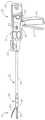
图1示出示例性进行关节运动的外科缝合器械的透视图;1 shows a perspective view of an exemplary articulating surgical stapling instrument;
图2示出了图1的器械的侧正视图;Figure 2 shows a side elevational view of the instrument of Figure 1;
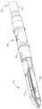
图3示出了图1器械的端部执行器的透视图,其中端部执行器处于闭合构型;Figure 3 shows a perspective view of the end effector of the apparatus of Figure 1 with the end effector in a closed configuration;
图4示出了图3的端部执行器的透视图,其中端部执行器处于打开构型;Figure 4 shows a perspective view of the end effector of Figure 3 with the end effector in an open configuration;
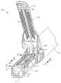
图5示出了图3的端部执行器的分解透视图;Figure 5 shows an exploded perspective view of the end effector of Figure 3;
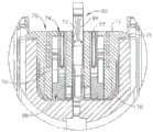
图6示出了图3的端部执行器沿图4的线6-6截取的剖面端视图;6 illustrates a cross-sectional end view of the end effector of FIG. 3 taken along line 6-6 of FIG. 4;
图7A示出了图3的端部执行器沿图4的线7-7截取的剖面侧视图,其中击发梁处于近侧位置;7A shows a cross-sectional side view of the end effector of FIG. 3 taken along line 7-7 of FIG. 4 with the firing beam in a proximal position;
图7B示出了图3的端部执行器沿图4的线7-7截取的剖面侧视图,其中击发梁处于远侧位置;7B shows a cross-sectional side view of the end effector of FIG. 3 taken along line 7-7 of FIG. 4 with the firing beam in a distal position;
图8示出了图3的被定位在组织处并已在组织中被致动了一次的端部执行器的透视图;Figure 8 shows a perspective view of the end effector of Figure 3 positioned at tissue and having been actuated once in tissue;
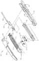
图9示出了另一个示例性关节运动外科缝合器械的侧正视图;9 shows a side elevational view of another exemplary articulation surgical stapling instrument;
图10示出了图9器械的端部执行器的透视图,其中端部执行器处于打开构型;Figure 10 shows a perspective view of the end effector of the apparatus of Figure 9 with the end effector in an open configuration;
图11示出了图10的端部执行器的下钳口的顶视图;Figure 11 shows a top view of the lower jaw of the end effector of Figure 10;
图12示出了图10的端部执行器的上钳口的底视图;Figure 12 shows a bottom view of the upper jaw of the end effector of Figure 10;
图13示出了图11的下钳口的分解透视图;Figure 13 shows an exploded perspective view of the lower jaw of Figure 11;
图14示出了图11的下钳口的顶视图;Figure 14 shows a top view of the lower jaw of Figure 11;
图15A示出了具有延伸穿过肝脏组织的血管的肝脏的示意图;Figure 15A shows a schematic diagram of a liver with blood vessels extending through liver tissue;
图15B示出了图10的端部执行器切断图15A的肝脏组织的示意图;15B shows a schematic diagram of the end effector of FIG. 10 severing the liver tissue of FIG. 15A;
图15C示出了从图15A的切断的肝脏组织暴露的图15B的血管的示意图;Figure 15C shows a schematic view of the blood vessel of Figure 15B exposed from the severed liver tissue of Figure 15A;
图15D示出了缝合图15C的暴露血管的图10的端部执行器的示意图;Figure 15D shows a schematic diagram of the end effector of Figure 10 sutured to the exposed vessel of Figure 15C;
图15E示出了暴露且缝合的图15D的血管的示意图;并且Figure 15E shows a schematic view of the vessel of Figure 15D exposed and sutured; and
图15F示出了具有一部分肝脏组织和从其切除的血管的图15A的肝脏的示意图。Figure 15F shows a schematic view of the liver of Figure 15A with a portion of liver tissue and blood vessels resected therefrom.
附图并非旨在以任何方式进行限制,并且能够设想本发明的各种实施方案可以多种其他方式来执行,包括那些未必在附图中示出的方式。结合在本说明书中并形成本说明书的一部分的附图例示了本发明的若干方面,并与描述一起用于解释本发明的原理;然而,应当理解,本发明不限于所示出的确切布置。The drawings are not intended to be limiting in any way, and it is contemplated that various embodiments of the invention may be carried out in various other ways, including those not necessarily shown in the drawings. The accompanying drawings, which are incorporated in and form a part of this specification, illustrate several aspects of the invention and, together with the description, serve to explain the principles of the invention; it is to be understood, however, that the invention is not limited to the precise arrangements shown.
具体实施方式Detailed ways
本发明的某些示例的以下说明不应用于限定本发明的范围。根据以举例的方式示出的以下说明,本发明的其他示例、特征、方面、实施方案和优点对于本领域的技术人员将是显而易见的,一种最佳方式被设想用于实施本发明。如将认识到,本发明能够具有其他不同且明显的方面,这些方面均不脱离本发明。因此,附图和说明应被视为实质上是例示性的而非限制性的。The following description of certain examples of the invention should not be used to limit the scope of the invention. Other examples, features, aspects, embodiments and advantages of the invention will be apparent to those skilled in the art from the following description, shown by way of example, and a best mode is contemplated for carrying out the invention. As will be realized, the invention is capable of other different and obvious aspects, all without departing from the invention. Accordingly, the drawings and description are to be regarded as illustrative in nature and not restrictive.
I.示例性外科缝合器I. Exemplary Surgical Staplers
图1示出包括柄部组件20、轴组件30和端部执行器40的示例性外科缝合和切断器械10。端部执行器40和轴组件30的远侧部分的尺寸被设计成用于在图1所示的非关节运动状态中穿过套管针插管插入患者的手术部位,以用于执行外科手术。仅以举例的方式,此种套管针可从患者的两个肋骨之间或其他地方插入患者的腹部中。在一些情况下,在不存在套管针的情况下使用器械10。例如,端部执行器40和轴组件30的远侧部分可通过胸廓切开术或其他类型的切口直接插入。应当理解,本文中使用的术语诸如“近侧”和“远侧”是相对于临床医生抓握器械10的柄部组件20而言的。因此,端部执行器40相对于更近侧的柄部组件20而位于远侧。还应当理解,为便利和清楚起见,本文相对于图式使用空间用语诸如“竖直”和“水平”。然而,外科器械能够在许多取向和位置中使用,并且这些术语并非旨在为限制性的和绝对的。FIG. 1 shows an exemplary surgical stapling and severing instrument 10 including a
A.示例性柄部组件和轴组件A. Exemplary Handle Assembly and Shaft Assembly
如图1至图2所示,本示例的柄部组件20包括手枪式握把22、闭合触发器24和击发触发器26。每个触发器24,26可朝向和远离手枪式握把22选择性地枢转,如将在下文中更详细地描述。柄部组件20还包括砧座释放按钮25、击发梁反向开关27和可移除电池组28。这些部件还将在下文中更详细地描述。当然,除了或代替上文所述的那些中的任何一者,柄部组件20可具有多种其他部件、特征和可操作性。参考本文的教导内容,柄部组件20的其他合适的构型对于本领域的普通技术人员将是显而易见的。As shown in FIGS. 1-2 , the
如图1至图3所示,本示例的轴组件30包括外部闭合管32、关节运动节段34和闭合环36,该闭合环与端部执行器40进一步联接。闭合管32沿轴组件30的长度延伸。闭合环36定位在关节运动节段34的远侧。闭合管32和闭合环36被构造成能够相对于柄部组件20纵向平移。闭合管32的纵向平移经由关节运动节段34而被传送到闭合环36。可用于提供闭合管32和闭合环36的纵向平移的示例性特征将在下文中更详细地进行描述。As shown in FIGS. 1-3 , the
关节运动节段34能够操作以侧向偏转闭合环36和端部执行器40,从而以期望的角度(α)侧向远离轴组件30的纵向轴线LA。由此,端部执行器40可从所需的角度或由于其他原因到达器官的后面或接近组织。在一些型式中,关节运动节段34能够使得端部执行器40沿单个平面偏转。在一些其他型式中,关节运动节段34能够使得端部执行器沿多于一个平面偏转。在本示例中,关节运动通过位于轴组件30的近侧端部的关节运动控制旋钮35而被控制。钮35能够围绕垂直于轴组件30的纵向轴线LA的轴线旋转。响应于旋钮35的旋转,闭合环36和端部执行器40围绕垂直于轴组件30的纵向轴线LA的轴线枢转。仅以举例的方式,旋钮35的顺时针旋转可引起闭合环36和端部执行器40在关节运动节段34处的对应的顺时针枢转。关节运动节段34被构造成能够将闭合管32的纵向平移传送到闭合环36,而无论关节运动节段34是处于笔直构型还是关节运动构型。
在一些型式中,关节运动节段34和/或关节运动控制旋钮35根据下列专利的教导内容中的至少一些来构造和操作:2014年8月28日公布的标题为“Surgical InstrumentEnd Effector Articulation Drive with Pinion and Opposing Racks”的美国公布2014/0243801,其公开内容以引用方式并入本文。关节运动节段34也可根据2014年6月25日提交的公开内容以引用方式并入本文的标题为“Articulation Drive Features forSurgical Stapler”的美国专利14/314,125,其公开内容以引用方式并入本文;并且/或者根据以下各种教导内容来构造和操作。参考本文的教导内容,关节运动节段34和关节运动旋钮35可采用的其他合适的形式对于本领域的普通技术人员将是显而易见的。In some versions, the
如图1至图2所示,本示例的轴组件30还包括旋钮31。旋钮31能够操作以使整个轴组件30和端部执行器40相对于柄部组件20围绕轴组件30的纵向轴线LA旋转。在一些型式中,旋钮31能够操作以选择性地锁定轴组件30和端部执行器40相对于柄部组件20围绕轴组件30的纵向轴线(LA)的角度定位。例如,旋钮31能够在第一纵向位置与第二纵向位置之间平移,在所述第一纵向位置中,轴组件30和端部执行器40可相对于柄部组件20围绕轴组件30的纵向轴线(LA)旋转;并且在所述第二纵向位置中,轴组件30和端部执行器40不可相对于柄部组件20围绕轴组件30的纵向轴线(LA)旋转。当然,除了或替代上文所述那些中任一者,轴组件30可具有多种其他部件、特征和可操作性。仅以举例的方式,轴组件30的至少一部分根据以下专利的教导内容中的至少一些来构造:2014年8月28日公布的标题为“Surgical Instrument with Multi-Diameter Shaft”的美国公布2014/0239038,其公开内容以引用方式并入本文。参考本文的教导内容,轴组件30的其他合适构型对于本领域的普通技术人员将是显而易见的。As shown in FIGS. 1 to 2 , the
B.示例性端部执行器B. Exemplary End Effector
同样如图3到图5所示,本示例的端部执行器40包括下钳口50和可枢转砧座60。砧座60包括被设置在下钳口50的对应弯曲狭槽54中的一对一体的向外延伸的销66。砧座60能够朝向和远离下钳口50在打开位置(示出出于图2和图4中)与闭合位置(示出出于图1、图3和图7A至图7B中)之间枢转。使用术语“能够枢转”(以及以“枢转”为基础的类似术语)不应被解读为必须要求围绕固定轴线进行枢转运动。例如,在本示例中,砧座60围绕由销66限定的轴线枢转,当砧座60朝下钳口50运动时,这些销沿下钳口50的弯曲狭槽54滑动。在此类型式中,枢轴线沿由狭槽54限定的路径平移,而砧座60同时围绕所述轴线枢转。除此之外或另选地,枢轴线首先可沿狭槽54滑动,然后在枢轴线已沿狭槽54滑动特定距离之后,砧座60围绕所述枢轴线枢转。应当理解,此种滑动/平移枢转运动被包含在诸如“枢转”(“pivot”、“pivots”、“pivoting”)、“枢转的”(“pivotal”)、“能够枢转的”(“pivotable”)等术语内。当然,一些型式可提供砧座60围绕保持固定且不在狭槽或通道内平移的轴线的枢转运动等。As also shown in FIGS. 3-5 , the
如图5充分示出的,本示例的下钳口50限定被构造成能够接收钉仓70的通道52。可将钉仓70插入到通道52中,可致动端部执行器40,并且然后可移除钉仓70并利用另一个钉仓70来替换。下钳口50因此可释放地保持钉仓70与砧座60对齐,以用于致动端部执行器40。在一些型式中,下钳口50根据以下专利的教导内容中的至少一些来构造:2014年8月28日公布的标题为“Installation Features for Surgical Instrument End EffectorCartridge”的美国公布第2014/0239044号,该公布的公开内容以引用方式并入本文。参考本文的教导内容,下钳口50可采用的其他合适的形式对于本领域的普通技术人员将是显而易见的。As best shown in FIG. 5 , the
如图4至图6充分示出的,本示例的钉仓70包括仓体71和被固定到仓体71的下侧的托盘76。仓体71的上侧呈现平台73,当砧座60处于闭合位置时,组织可压靠在所述平台上。仓体71还限定纵向延伸通道72和多个钉凹坑74。钉77被定位在每个钉凹坑74中。钉驱动器75也被定位在每个钉凹坑74中,位于对应钉77下面以及托盘76上方。如将在下文中更详细地描述的,钉驱动器75能够操作以在钉凹坑74中向上平移,以由此向上驱动钉77穿过钉凹坑74并与砧座60接合。钉驱动器75被楔形滑动件78向上驱动,所述楔形滑动件被捕获在仓体71与托盘76之间并纵向平移穿过仓体71。楔形滑动件78包括一对倾斜成角的凸轮表面79,这对倾斜成角的凸轮表面被构造成能够接合钉驱动器75,并由此当楔形滑动件78纵向平移穿过仓70时向上驱动钉驱动器75。例如,当楔形滑动件78处于如图7A所示的近侧位置中时,钉驱动器75处于向下位置中并且钉77位于钉凹坑74中。当通过平移刀构件80将楔形滑动件78驱动到如图7B所示的远侧位置时,楔形滑动件78向上驱动钉驱动器75,由此驱动钉77离开钉凹坑74并进入钉成形凹坑64中。因此,当楔形滑动件78沿水平维度平移时,钉驱动器75沿竖直维度平移。As best shown in FIGS. 4-6 , the
应当理解,钉仓70的构型可以多种方式改变。例如,本示例的钉仓70包括位于通道72的一侧的两排纵向延伸的钉凹坑74;以及位于通道72的另一侧上的另一组两排纵向延伸的钉凹坑74。然而,在一些其他型式中,钉仓70在通道72的每一侧包括三个、一个或一些其他数目的钉凹坑74。在一些型式中,钉仓70根据以下公布的教导内容中的至少一些来构造和操作:2014年8月28日提交的标题为“Integrated Tissue Positioning and JawAlignment Features for Surgical Stapler”的美国公布第2014/0239042号,该专利的公开内容以引用方式并入本文。除此之外或另选地,钉仓70可根据以下公布的教导内容中的至少一些来构造和操作:2014年8月28日公布的标题为“Installation Features forSurgical Instrument End Effector Cartridge”的美国公布第2014/0239044号,该公布的公开内容以引用方式并入本文。参考本文的教导内容,钉仓70可采用的其他合适的形式对于本领域的普通技术人员将是显而易见的。It should be understood that the configuration of the
如在图4中最佳所见,本示例的砧座60包括纵向延伸通道62和多个钉成形凹坑64。通道62被构造成能够当砧座60处于闭合位置时与钉仓70的通道72对齐。每个钉成形凹坑64被定位成当砧座60处于闭合位置时位于钉仓70的对应钉凹坑74上方。钉成形凹坑64被构造成能够当驱动钉77穿过组织进入砧座60时使钉77的腿变形。具体地,钉成形凹坑64被构造成能够使钉77的腿弯曲,以将成形钉77固定在组织中。砧座60可根据以下来构造:2014年8月28日公布的标题为“Integrated Tissue Positioning and Jaw Alignment Featuresfor Surgical Stapler”的美国专利公布2014/0239042;2014年8月28日公布的标题为“JawClosure Feature for End Effector of Surgical Instrument”的美国专利公布2014/0239036;和/或2014年8月28日公布的标题为“Staple Forming Features for SurgicalStapling Instrument”的美国公布2014/0239037,上述公布的公开内容以引用方式并入本文。参考本文的教导内容,砧座60可采用的其他合适的形式对于本领域的普通技术人员将是显而易见的。As best seen in FIG. 4 , the
在本示例中,刀构件80被构造成能够通过端部执行器40而平移。如图5和图7A至图7B充分示出的,刀构件80被固定到击发梁82的远侧端部,该击发梁延伸穿过轴组件30的一部分。如图4和图6充分示出,刀构件80被定位在砧座60的通道62和钉仓70的通道72中。刀构件80包括朝远侧呈现的切割刃84,所述切割刃被构造成能够当刀构件80朝远侧平移穿过端部执行器40时切断被压缩在砧座60和钉仓70的平台73之间的组织。如上文所指出并如图7A至图7B所示,当刀构件80通过端部执行器40朝远侧平移时,刀构件80也朝远侧驱动楔形滑动件78,由此驱动钉77穿过组织并抵靠砧座60成形。可用于通过端部执行器40朝远侧驱动刀构件80的各种特征部将在下文中更详细地进行描述。In this example, the
在一些型式中,端部执行器40包括闭锁特征部,该闭锁特征部被构造成能够当钉仓70未插入下钳口50中时阻止刀构件80通过端部执行器40朝远侧推进。除此之外或另选地,端部执行器40可包括闭锁特征部,该闭锁特征部被构造成能够当已被致动一次(例如,其中从中布置所有钉77)的钉仓70插入到下钳口50中时阻止刀构件80通过端部执行器40朝远侧推进。仅以举例的方式,此类闭锁特征部可根据以下美国专利的教导内容中的至少一些来构造:2014年8月28日公布的标题为“Lockout Feature for Movable Cutting Memberof Surgical Instrument”的美国专利公布2014/0239041,其公开内容以引用方式并入本文;和/或2014年6月25日提交的标题为“Articulation Drive Features for SurgicalStapler”的美国专利申请14/314,108(其公开内容以引用方式并入本文)的教导内容中的至少一些来构造。参考本文的教导内容,闭锁特征部可采用的其他合适的形式对于本领域的普通技术人员将是显而易见的。另选地,端部执行器40可简单地省去此类闭锁特征部。In some versions, the
C.砧座的示例性致动C. Exemplary Actuation of the Anvil
在本示例中,通过相对于端部执行器40朝远侧推动闭合环36而朝下钳口50驱动砧座60。响应于闭合环36相对于端部执行器40的远侧平移,闭合环36通过凸轮作用与砧座60协作,以朝向下钳口50驱动砧座60。类似地,响应于闭合环36相对于端部执行器40的近侧平移,闭合环36可与砧座60协作,以远离下钳口50而打开砧座60。仅以举例的方式,闭合环36和砧座60可根据以下专利的教导内容中的至少一些来相互作用:2014年8月28日公布的标题为“Jaw Closure Feature for End Effector of Surgical Instrument”的美国专利公布2014/0239036,其公开内容以引用方式并入本文;和/或2014年6月25日提交的标题为“Jaw Opening Feature for Surgical Stapler”的美国专利申请14/314,108,其公开内容以引用方式并入本文。可用于提供闭合环36相对于端部执行器40的纵向平移的示例性特征部将在下文中更详细地描述。In this example, the
如上所述,柄部组件20包括手枪式握把22和闭合触发器24。同样如上文所指出,响应于闭合环36的远侧推进,砧座60朝向下钳口50闭合。在本示例中,闭合触发器24可朝向手枪式握把22枢转以朝远侧驱动闭合管32和闭合环36。参考本文的教导内容,可用于将闭合触发器24朝手枪式握把22的枢转运动转化成闭合管32和闭合环36相对于柄部组件20的远侧平移的各种合适的部件对于本领域的普通技术人员将是显而易见的。当闭合触发器24达到完全枢转状态使得砧座60相对于下钳口50处于完全闭合位置时,柄部组件20中的锁定特征部锁定闭合触发器24和闭合管32的位置,由此将砧座60相对于下钳口50锁定在完全闭合位置。这些锁定特征部通过致动砧座释放按钮25而释放。砧座释放按钮25被构造成并定位成能够由抓握手枪式握把22的操作者的手的拇指致动。换句话讲,操作者可利用一只手来抓握手枪式握把22,利用同一只手的一个或多个手指来致动闭合触发器24,并且然后利用同一只手的拇指来致动砧座释放按钮25,而无需利用同一只来手释放手枪式握把22的抓握。参考本文的教导内容,可用于致动砧座60的其他合适特征部对于本领域的普通技术人员将是显而易见的。As mentioned above, the
D.击发梁的示例性致动D. Exemplary Actuation of the Firing Beam
在本示例中,器械10提供对击发梁82的机动化控制。具体地,器械10包括机动化部件,所述机动化部件被构造成能够响应于击发触发器26朝向手枪式握把22枢转而朝远侧驱动击发梁82。在一些型式中,马达(未示出)容纳在手枪式握把22中并且从电池组28接收电力。此马达与传输组件(未示出)联接,所述传输组件将马达的驱动轴的旋转动作转换成击发梁82的线性平移。在一些此类型式中,击发梁82可仅在砧座60相对于下钳口50处于完全闭合位置时朝远侧推进。如上面参照图7A至图7B所述,在击发梁82朝远侧推进而切断组织并驱动钉77之后,用于击发梁82的驱动组件可自动反向以将击发梁82朝近侧驱动回到回缩位置(例如,从图7B所示的位置回到图7A所示的位置)。另选地,操作者可致动击发梁反向开关27,这可使得用于击发梁82的驱动组件反向以便将击发梁82回缩到近侧位置。本示例的柄部组件20还包括应急特征部21,该应急特征部能够操作以提供机械应急,由此允许操作者手动地朝近侧回缩击发梁82(例如,万一在击发梁82处于远侧位置时出现电力丢失的情况等等)。In this example, the instrument 10 provides motorized control of the firing beam 82 . Specifically, the instrument 10 includes motorized components configured to drive the firing beam 82 distally in response to the firing
仅以举例的方式,能够操作以提供击发梁82的机动化致动的这些特征部可根据以下专利的教导内容中的至少一些来构造和操作:2012年7月3日公布的标题为“Motor-Driven Surgical Instrument”的美国专利8,210,411,其公开内容以引用方式并入本文。作为另一个仅例示性示例,能够操作以提供击发梁82的机动化致动的这些特征部可根据以下专利的教导内容中的至少一些来构造和操作:2013年6月4日公布的标题为“Motor-Driven Surgical Cutting Instrument with Electric Actuator Directional ControlAssembly”的美国专利8,453,914,其公开内容以引用方式并入本文。作为另一个仅例示性示例,能够操作以提供击发梁82的机动化致动的这些特征部可根据以下专利申请的教导内容中的至少一些来构造和操作:2014年3月26日提交的标题为“Surgical InstrumentComprising a Sensor System”的美国专利申请14/226,142,其公开内容以引用方式并入本文。By way of example only, the features operable to provide motorized actuation of firing beam 82 may be constructed and operated in accordance with at least some of the teachings of the following patents: Issued July 3, 2012 entitled "Motor - US Patent 8,210,411 to Driven Surgical Instrument", the disclosure of which is incorporated herein by reference. As another merely illustrative example, the features operable to provide motorized actuation of firing beam 82 may be constructed and operated in accordance with at least some of the teachings of the following patents: Issued June 4, 2013 entitled US Patent 8,453,914 for "Motor-Driven Surgical Cutting Instrument with Electric Actuator Directional Control Assembly," the disclosure of which is incorporated herein by reference. As another merely illustrative example, the features operable to provide motorized actuation of firing beam 82 may be constructed and operated in accordance with at least some of the teachings of the following patent application: Title filed March 26, 2014 US Patent Application 14/226,142 for "Surgical Instrument Comprising a Sensor System," the disclosure of which is incorporated herein by reference.
参考本文的教导内容,可用于提供击发梁82的机动化的其他合适的部件、特征部和构型对于本领域的普通技术人员将是显而易见的。还应当理解,一些其他型式可提供对击发梁82的手动驱动,使得马达可被省略。仅以举例的方式,击发梁82可根据本文引用的任何其他参考文献的教导内容中的至少一些来手动地致动。Other suitable components, features, and configurations that may be used to provide motorization of firing beam 82 will be apparent to those of ordinary skill in the art in view of the teachings herein. It should also be appreciated that some other versions may provide manual drive to the firing beam 82 so that the motor may be omitted. By way of example only, firing beam 82 may be manually actuated in accordance with at least some of the teachings of any of the other references cited herein.
图8示出了已通过单个行程被致动穿过组织90的端部执行器40。如图所示,切割刃84(在图8中被遮住)已切穿组织90,同时钉驱动器75已驱动两排交错的钉77穿过由切割刃84产生的切割线的每一侧的组织90。在此示例中,钉77全部与切割线基本上平行地取向,但应当理解,钉77可以任何合适的取向定位。在本示例中,在第一行程完成之后,从套管针取出端部执行器40,利用新钉仓70来替换已空钉仓70,并且随后端部执行器40再次插入穿过套管针而到达缝合位点以用于进行进一步的切割和缝合。此过程可重复进行,直到已提供期望量的切口和钉77。砧座60可需要闭合以有利于通过套管针的插入和取出;并且砧座60可需要打开以有利于钉仓70的替换。Figure 8 shows the
应当理解,在每次致动行程期间,切割刃84可基本上在钉77被驱动穿过组织的同时切割组织。在本示例中,切割刃84仅稍微落后于钉77的驱动,使得钉77正好在切割刃84穿过组织之前被驱动穿过该组织的相同区域,但应理解,这个顺序可颠倒,或者切割刃84可直接与相邻的钉同步。虽然图8示出了在组织90的两个层92,94中被致动的端部执行器40,但应当理解,端部执行器40可被致动穿过组织90的单个层或组织的多于两个层92,94。还应当理解,与切割刃84产生的切割线相邻的钉77的成形和定位可基本上密封切割线处的组织,由此减少或防止切割线处的出血和/或其他体液的渗漏。此外,尽管图8示出端部执行器40在组织的两个基本上平坦的相反平面层92,94中致动,但应当理解,端部执行器40也可在管状结构诸如血管、胃肠道的一部分等上致动。因此,不应将图8视为对端部执行器40的设想用途进行任何限制。参考本文的教导内容,其中可使用器械10的各种合适情况和程序对于本领域的普通技术人员将是显而易见的。It should be appreciated that during each actuation stroke, the cutting edge 84 may cut tissue substantially simultaneously with the
还应当理解,器械10的任何其他部件或特征部可根据本文所述的各种参考文献中的任一者来构造和操作。可提供用于器械10的其他示例性修改将在下文中更详细地描述。下述教导内容可并入器械10内的各种合适方式对于本领域的普通技术人员将是显而易见的。类似地,可将下述教导内容与本文引用的参考文献的各种教导内容进行组合的各种合适方式对于本领域的普通技术人员将是显而易见的。还应当理解,下述教导内容并不限于本文引用的参考文献中教导的器械10或装置。下述教导内容可易于应用到各种其他种类的器械,所述器械包括将不被归类为外科缝合器的器械。参考本文的教导内容,其中可应用下文教导内容的各种其他合适的装置和情况对本领域的普通技术人员将是显而易见的。It should also be understood that any other components or features of instrument 10 may be constructed and operated in accordance with any of the various references described herein. Other exemplary modifications that may be provided for instrument 10 are described in greater detail below. Various suitable ways in which the following teachings may be incorporated into device 10 will be apparent to those of ordinary skill in the art. Similarly, various suitable ways in which the following teachings may be combined with the various teachings of the references cited herein will be apparent to those of ordinary skill in the art. It should also be understood that the following teachings are not limited to the apparatus 10 or devices taught in the references cited herein. The following teachings can be readily applied to various other classes of instruments, including instruments that would not be classified as surgical staplers. Various other suitable devices and situations in which the following teachings may be applied will be apparent to those of ordinary skill in the art in view of the teachings herein.
II.示例性另选缝合端部执行器II. Exemplary Alternative Suture End Effectors
虽然上述外科器械10提供了可用于缝合和切断患者体内组织的端部执行器40的一个示例,但应理解的是,人体包括各种各样的组织,这些组织位于整个患者的不同的、有时是难以接近的部位。例如,肝脏包括具有遍及全身的血管或管腔的组织。在肝脏包含肿瘤的环境中,可能需要切除含有肿瘤的肝脏部分。切除可以是解剖的(例如,切除肝脏的右侧或左侧,包括该侧的叶)或非解剖的(例如,仅切除肝组织的单个叶或楔形部)。该切除过程可能需要至少三种步骤—第一步,将血管或管腔周围的组织(例如肝实质)解剖,从而分离或露出血管或管腔;第二步,结扎那些血管或管腔;第三步,切断结扎的血管或管腔。While the above-described surgical instrument 10 provides one example of an
一种此类肝脏切除方法包括众所周知的弯血管钳法,其中使用弯血管钳来压缩肝脏组织,从而通过挤压作用解剖组织。但是,治疗可能需要许多器械以适应人体内的各种组织和血管或管腔,从而增加与评估组织状态、选择和/或改变器械、执行切除相关联的时间和复杂性。因此可能期望提供具有端部执行器212的外科器械210,该端部执行器具有一对挤压表面214,216,这一对挤压表面被构造成能够通过挤压组织来切断组织;同时还提供相邻的钉仓218以选择性地结扎穿过组织的一个或多个血管或管腔。由此,单个外科器械210将允许操作者更快速地评估组织,并且进行进一步的组织解剖和/或血管和管腔的结扎。One such method of liver resection includes the well-known curved vascular clamp method, in which a curved vascular clamp is used to compress liver tissue, thereby dissecting the tissue by compressive action. However, treatment may require many instruments to accommodate various tissues and vessels or lumens in the human body, thereby increasing the time and complexity associated with assessing tissue status, selecting and/or changing instruments, and performing resections. It may therefore be desirable to provide a
以下通过利用挤压表面214,216解剖肝脏组织(例如,肝实质)并使用钉结扎相关血管或管腔(例如,门静脉、肝静脉分支、肝动脉分支、肝外血管等)为背景,描述了外科器械210。在一些情况下(例如,在肝静脉分支和肝动脉分支等的情况下),当操作者用表面214,216挤压肝脏组织时,暴露出由钉密封的血管或管腔。在一些其他情况下(例如,在门静脉和肝外血管等的情况下),由钉密封的血管或管腔与操作者用表面214,216挤压的肝脏组织分开。尽管以肝脏切除为背景提供了外科器械210和治疗方法的以下描述,但是应当理解,外科器械210可以可选地被构造成能够治疗人体内具有相似特征的任何组织。还应当理解,下文所述的特征部可易于与上述外科器械10结合。为此,相似标号指示上文更详细描述的相似特征部。Surgical instruments are described below in the context of dissecting liver tissue (eg, liver parenchyma) using
在以下示例中,端部执行器212施加至少两个侧向间隔开的钉排,其中一排中的钉与另一排中的钉具有相同的高度。在一些变型中,端部执行器212被修改为施加至少两个侧向间隔开的钉排,其中一排中的钉的高度与另一排中的钉的高度不同。In the following example, the
A.具有曲面端部执行器的示例性缝合器械A. Exemplary Stapling Instrument with Curved End Effector
图9至图12示出了具有末端执行器212的外科器械210,该端部执行器具有上挤压表面214、下挤压表面216和钉仓218。外科器械210还包括上面更详细讨论的柄部组件20和轴组件30。除非下文另有说明,结合柄部组件20和轴组件30的端部执行器212被构造成能够与端部执行器40类似并且可类似地进行操作(参见图1)。FIGS. 9-12 illustrate a
本示例的端部执行器212还包括下钳口220和上钳口222。上钳口222使砧座(224)成形并且相对于下钳口220可枢转地安装以用于在其间接收组织。更具体地讲,砧座224可在打开位置和关闭位置之间(例如,响应于触发器24朝向和远离手枪式握持部22的枢转运动)朝向和远离下钳口220枢转。例如,在本示例中,砧座224围绕由销(未示出)限定的轴线枢转,当砧座224朝下钳口220移动时,这些销沿下钳口220的弯曲狭槽(未示出)滑动。在此类型式中,枢轴线沿由狭槽(未示出)限定的路径平移,而砧座224同时围绕所述轴线枢转。除此之外或另选地,枢轴线首先可沿狭槽(未示出)滑动,然后在枢轴线沿狭槽(未示出)滑动特定距离之后,砧座224围绕所述枢轴线枢转。另选地,一些型式可提供砧座224围绕保持固定且不在狭槽或通道内平移的轴线的枢转运动等。The
如图10和图11充分示出,本示例的下钳口220限定被构造成能够接收钉仓218的通道226。可将钉仓218插入到通道226中,可致动端部执行器212,并且然后可移除钉仓218并利用其他钉仓218来替换。下钳口220因此将钉仓218可释放地保持成与砧座224对准,以用于致动端部执行器212。在一些另选型式中,钉仓218的部件完全整合到下钳口220中,使得端部执行器212只可使用一次。参考本文的教导内容,下钳口220可采用的其他合适的形式对于本领域的普通技术人员而言将是显而易见的。As best shown in FIGS. 10 and 11 , the
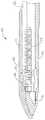
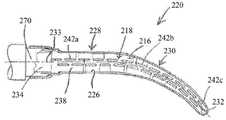
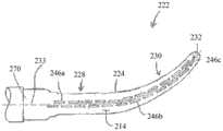
端部执行器212通常成形为在外科手术过程中改善通向组织的通路。更具体地讲,端部执行器212具有从闭合环36突出并且延伸到弧形部分230的线性部分228。在一个示例中,弧形部分230相对于线性部分228横向于右侧(当从上方观察时)弯曲。然而,应当理解,弧形部分230可以另选地相对于线性部分228横向于左侧(当从上面观察时)弯曲。在任何情况下,如图11至图13所示,下钳口和上钳口220,222限定线性和弧形部分228,230。另外,下钳口和上钳口220,222是锥形的,使得端部执行器在横向尺寸上朝向端部执行器212的远侧末端232变窄,以进一步进入组织。因此,沿端部执行器212的横向宽度的中心线233沿着端部执行器212随着其线性部分和弧形部分228,230纵向延伸。The
通过进一步限定端部执行器212的线性部分和弧形部分228,230以及渐缩,钉仓218容纳下钳口和上钳口220,222的形状。为此,本示例的钉仓218包括仓体234和被固定到仓体234的下侧的托盘(未示出)。仓体234的上侧呈现平台238,当砧座224处于闭合位置时,组织可被压缩贴靠该平台。在一些型式中,下挤压表面216沿钉仓218定位。然而,应当理解,下挤压表面216以及配合的上挤压表面214可以可选地沿着端部执行器212定位,从而通过压缩来切断组织。The
仓体234进一步限定沿循沿着平台238的中心线233的预定图案的多个钉凹坑242a,242b,242c。更具体地讲,钉仓218包括两排纵向延伸的钉凹坑242a,242b,242c,在中心线233的左侧具有左排,在中心线233的右侧具有右排。
多个钉244a,244b,244c中的一个钉定位在相应的钉凹坑242a,242b,242c中。左排和右排的钉凹坑242a,242b,242c被构造成能够在横向于中心线233的方向上重叠,以便将多个钉244a,244b,244c安装在组织内并且阻止其间的开口,以改善结扎。换句话讲,在本示例中,在相邻钉凹坑242a,242b,242c之间保持一致的空隙(G1)(参见图14)以实现一致的重叠。如本文所用,术语“重叠”旨在包括:某个特征部在至少一个方向上与另一个特征部重叠。因此,如果这些特征部在至少一个平面(诸如包括横向方向的横向平面)中重叠,某个特征部可以如本文所述从另一个特征部偏移并且仍然重叠。虽然如下面更详细地讨论的那样示例性仓234包括具有钉244a,244b,244c的各种钉凹坑242a,242b,242c以便容纳弧形部分230,但应当理解,钉仓218的构型可以多种方式改变。参考本文的教导内容,钉仓218可采用的其他合适形式对于本领域的普通技术人员将是显而易见的。One of the plurality of
如图12充分示出,本示例的砧座224具有多个钉成形凹坑246a,246b,246c。每个钉成形凹坑246a,246b,246c被定位成当砧座224处于闭合位置中时位于钉仓218的对应钉凹坑242a,242b,242c上方。钉成形凹坑246a,246b,246c被构造成能够当钉244a,244b,244c被驱动穿过组织进入砧座224时使钉244a,244b,244c的支脚248变形。具体地,钉成形凹坑246a,246b,246c被构造成能够使钉244a,244b,244c的支脚248弯曲,以将成形钉244a,244b,244c固定在组织中。参考本文的教导内容,砧座224可采用的其他合适形式对于本领域的普通技术人员将是显而易见的。12, the
如图13所示,钉仓218包括定位在钉仓242a,242b,242c中的钉排驱动器252和十字钉驱动器254,在对应组的钉244a,244b,244c下方,并且在托盘(未示出)上方。如将在下文中更详细地描述,钉驱动器252,254能够操作以在钉凹坑242a,242b,242c中向上平移,从而向上驱动钉244a,244b,244c穿过钉凹坑242a,242b,242c并与砧座224接合。钉驱动器252,254由朝远侧平移的楔形滑动件256向上驱动,该楔形滑动件被捕集在仓体234和托盘(未示出)之间,并且沿着凸轮槽257纵向平移穿过仓体234。楔形滑动件256包括具有前凸轮表面260、中间凸轮表面262和后凸轮表面264的凸轮斜面258。仅以举例的方式,前凸轮表面260可相对于水平平面成约45°的角度;并且中间凸轮表面262可相对于水平平面成约22°的角度。另选地,可使用任何其他合适的角度。凸轮斜面258通常被构造成能够接合钉驱动器252,254,并且由此当楔形滑动件256纵向平移穿过钉仓218从近侧滑动件位置移动到远侧滑动件位置时向上驱动钉驱动器252,254。例如,当楔形滑动件256处于近侧滑动位置时,钉驱动器252,254处于向下位置并且钉244a,244b,244c位于平台238下方的钉凹坑442中。As shown in FIG. 13, the
楔形滑动件256由平移构件266朝远侧驱动。仅以举例的方式,平移构件266可通过致动触发器26朝远侧平移。因此平移构件266可以类似于上述击发梁82的方式操作,但是平移构件266缺少切割边缘84而不能切断组织。当楔形滑动件256通过平移构件266被驱动到远侧滑动件位置时,楔形滑动件256向上驱动钉驱动器252,254,从而驱动钉244a,244b,244c离开钉凹坑242a,242b,242c并进入钉成形凹坑246a,246b,246c。因此,当楔形滑动件256沿水平平面平移时,钉驱动器252,254沿对应的竖直平面平移。
1.端部执行器的示例性线性部分和弧形部分1. Exemplary linear and arcuate sections of the end effector
具有线性部分228和弧形部分230的端部执行器212被构造成能够在治疗期间提供通向患者体内的组织的更大通路。图13和图14更详细地示出具有四个不同部分的下钳口220,所述四个不同部分按顺序沿着中心线233从下钳口220的近侧端部部分270、线性部分228、弧形部分230纵向延伸到钉仓218的远侧末端232。如此,下钳口220中的通道226被构造成能够接收钉仓218并共同限定这些部分270,228,230,232。The
本示例的下钳口220在钉仓218的邻接部272,274与下钳口部220的对应邻接部276,278之间的通道226内包括钉仓218,如图14所示。因此,通道226有效地支撑钉仓218,其中钉仓218的邻接部272,274被下钳口220的对应邻接部276,278捕获,以将钉仓218固定在水平平面中。下钳口220和钉仓218还设置有对应的卡位(未示出),以将钉仓218可释放地固定在垂直平面中。由于通道226接收钉仓218,因此下钳口222的外部宽度(W1,W2,W3)由下钳口222的环绕壁限定。相比之下,钉仓218的远侧末端232朝远侧突出超过下钳口222,并且因此限定使用中的下钳口220的外部宽度(W4)。然而,应当理解,钉仓218与下钳口220之间的布局可以改变,使得任一特征部可以限定下文所论述的特定尺寸。因此,参考本文的教导,具有宽度(W1,W2,W3,W4)的端部执行器212的其他合适构型对于本领域的技术人员将是显而易见的。The
近侧端部部分270限定近侧宽度(W1),该宽度通常是宽度(W1,W2,W3,W4)的最宽部分,这是因为近侧端部部分270分别包括钉仓218的邻接部274和下钳口222的邻接部278。端部执行器212从近侧端部部分270变窄到限定线性宽度W2的线性部分228。在一个示例中,线性宽度(W2)沿着整个线性部分228的中心线233大致恒定。线性部分228朝远侧延伸至弧形部分230。The
本示例的弧形部分230从线性部分228朝向远侧末232连续渐缩,使得弧形宽度可变,但具有平均弧形宽度(W3),如图14所示。因此,弧形部分230弯曲并渐缩以改善组织内的通路。虽然弧形部分230的远侧端部比远侧末端232更窄以容纳对应的邻接部276,278,但远侧宽度(W4)通常比宽度(W1,W2,W3)窄,如上所述。远侧末端232从弧形部分228朝远侧延伸,并且为大致倒圆的,使得远侧末端232可用于挤压组织并隔离组织,而不必刺穿、切割或撕裂与远侧末端232接触的组织。虽然上述特征部中的许多特征部已相对于下钳口216具体描述,但应当理解,对应的近侧端部部分270、线性部分228、弧形部分230和远侧末端232也包括在上钳口212中(参见图13)。The
2.组织切除的示例性方法2. Exemplary Methods of Tissue Resection
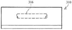
图15A至图15F示出了使用端部执行器212来切除组织诸如肝实质组织310,并且将血管或管腔316结扎在其中的一个示例。如上所述,血管或管腔316可以包括肝静脉或肝动脉。还应当理解,该方法可以进一步包括使用端部执行器212结扎其他血管,诸如门静脉和肝外血管等。Figures 15A-15F show one example of using the
如图15B所示,操作者将端部执行器212定位成使得包括血管或管腔316的组织310位于下钳口和上钳口220,222之间。然后,操作者在上钳口和下钳口220,222分别的上挤压表面和下挤压表面214,216之间压缩组织310,以将预定的挤压压力传递到组织310。仅以举例的方式,可以通过使触发器24朝向手枪式握持部22枢转而以这种方式致动钳口220,222。应当理解,钳口220,222不一定被致动到完全闭合的构型。在一些情况下,操作者可依靠通过触发器24和手枪式握持部22给出的触觉反馈来确定操作者是否已经在钳口220,222之间实现期望的空隙,以适当地挤压组织310而不会不利地损坏血管或管腔316。除此之外或另选地,操作者可以依赖于视觉反馈。As shown in Figure 15B, the operator positions the
在任何情况下,由钳口220,222施加的挤压压力有效地切断组织310,然后操作者从组织310移除端部执行器212以查看是否存在任何血管或管腔316。如图15C中所示,血管或管腔316保持完整并且被暴露,在组织310的切断部分之间延伸。In any event, the compressive pressure exerted by the
在一些情况下,操作者可以保持血管或管腔316完好。然而,在本示例中,操作者结扎血管或管腔316以完成切除组织310的切断部分,如图15D和图15E所示。如上面更详细地讨论的,结扎包括将至少一些重叠的钉244a,244b,244c放置在血管或管腔316内。因此,应当理解,可以使用相同的端部执行器212来挤压(并因此切断)肝脏组织310,并且将组织310中的血管或管腔316结扎。在本示例中,在将血管或管腔316结扎之后,操作者从肝脏组织31移除端部执行器212,并且使用在本领域中是已知的用于切割组织的另一外科器械诸如传统的刀或剪刀等(未示出)切断血管或管腔316。由此,操作者完成组织的右侧部分310和血管或管腔316的对应部分的切除,如图15F所示。施加的钉244a密封血管或管腔316的切断端部318。In some cases, the operator may leave the vessel or
如上所述,操作者移除端部执行器212以观察血管316,如图15C所示。另选地,操作者可以施加预先确定的挤压压力(或如上所述基于触觉和/或视觉反馈确定),如图15B所示,然后在随后立即结扎残留在其中的任何组织,诸如血管或管腔316。因此,无需观察组织,但是在一个或多个肝脏切除手术中,操作者可发现这样的观察是期望的。应当理解,以上描述的切除仅仅是说明性的,并且不限于肝脏组织。另选地,可以根据用户的需要,利用端部执行器212在患者体内的其他组织上执行组织切除。As described above, the operator removes the
III.示例性组合III. Exemplary Combinations
下述实施例涉及本文的教导内容可被组合或应用的各种非穷尽性方式。应当理解,下述实施例并非旨在限制可在本申请或本申请的后续提交文件中的任何时间提供的任何权利要求的覆盖范围。不旨在进行免责声明。提供以下实施例仅仅是出于例示性目的。设想到,本文的各种教导内容可按多种其他方式进行布置和应用。还设想到,一些变型可省略在以下实施例中所提及的某些特征。因此,下文提及的方面或特征中的任一者均不应被视为决定性的,除非另外例如由发明人或关注发明人的继承者在稍后日期明确指明如此。如果本申请或与本申请相关的后续提交文件中提出的任何权利要求包括下文提及的那些特征之外的附加特征,则这些附加特征不应被假定为因与专利性相关的任何原因而被添加。The following embodiments relate to various non-exhaustive ways in which the teachings herein may be combined or applied. It should be understood that the following examples are not intended to limit the scope of coverage of any claims that may be presented at any time in this application or subsequent filings of this application. Not intended to make a disclaimer. The following examples are provided for illustrative purposes only. It is contemplated that the various teachings herein may be arranged and applied in various other ways. It is also contemplated that some variations may omit certain features mentioned in the following embodiments. Accordingly, any of the aspects or features mentioned below should not be considered conclusive unless otherwise expressly indicated to do so at a later date, eg, by the inventor or a successor of the inventor concerned. If any claims presented in this application or in subsequent filings related to this application include additional features other than those mentioned below, these additional features shall not be presumed to be excluded for any reason in connection with patentability Add to.
实施例1Example 1
一种用于处理患者的组织的外科器械,包括:(a)轴组件;(b)从该轴组件沿着钳口中心线延伸的端部执行器,该端部执行器包括:(i)具有砧座的第一钳口,该砧座被构造成能够使压靠砧座的多个钉成形;以及(ii)第二钳口,其中第一钳口和第二钳口被构造成能够在打开构型和闭合构型之间转变,其中第一钳口和第二钳口限定端部执行器的直部分和端部执行器的弧形部分,该弧形部分从直部分朝远侧延伸,使得端部执行器的弧形部分被构造成能够提供通向患者体内组织的通路以用于治疗。A surgical instrument for treating tissue of a patient, comprising: (a) a shaft assembly; (b) an end effector extending from the shaft assembly along a jaw centerline, the end effector comprising: (i) a first jaw having an anvil configured to form a plurality of staples pressed against the anvil; and (ii) a second jaw, wherein the first and second jaws are configured to enable Transitioning between an open configuration and a closed configuration, wherein the first and second jaws define a straight portion of the end effector and an arcuate portion of the end effector, the arcuate portion extending distally from the straight portion Extends such that the arcuate portion of the end effector is configured to provide access to tissue in the patient for treatment.
实施例2Example 2
根据实施例1所述的外科器械,其中直部分限定大致垂直于中心线的近侧横向宽度,其中弧形部分限定大致垂直于中心线的远侧横向宽度,其中端部执行器从直部分朝向弧形部分向内渐缩,使得远侧横向宽度比近侧横向宽度窄。The surgical instrument of embodiment 1, wherein the straight portion defines a proximal lateral width substantially perpendicular to the centerline, wherein the arcuate portion defines a distal lateral width substantially perpendicular to the centerline, and wherein the end effector faces from the straight portion toward The arcuate portion tapers inwardly so that the distal lateral width is narrower than the proximal lateral width.
实施例3Example 3
根据实施例2所述的外科器械,其中弧形部分的远侧横向宽度沿着中心线从直部分朝向中心线远侧向内渐缩。The surgical instrument of
实施例4Example 4
根据实施例3所述的外科器械,其中端部执行器包括远侧末端,其中弧形部分从直部分朝向中心线向内渐缩到远侧末端。The surgical instrument of
实施例5Example 5
根据实施例1至4中任一项或多项所述的外科器械,还包括被接收在第二钳口内的钉仓,该钉仓包括:(i)面向砧座的平台,(ii)穿过平台形成的多个钉开口,以及(iii)分别定位于所述多个钉开口内的多个钉。The surgical instrument of any one or more of Embodiments 1 to 4, further comprising a staple cartridge received within the second jaw, the staple cartridge comprising: (i) an anvil-facing platform, (ii) a staple cartridge A plurality of staple openings formed through the platform, and (iii) a plurality of staples each positioned within the plurality of staple openings.
实施例6Example 6
根据实施例5所述的外科器械,其中所述多个钉开口包括第一排钉开口和第二排钉开口,其中第一排钉开口和第二排钉开口被定位在中心线的相应侧上并形成在平台上直部分和弧形部分的每一者中。The surgical instrument of embodiment 5, wherein the plurality of staple openings comprises a first row of staple openings and a second row of staple openings, wherein the first row of staple openings and the second row of staple openings are positioned on respective sides of a centerline and formed in each of the straight portion and the arcuate portion on the platform.
实施例7Example 7
根据实施例6所述的外科器械,其中第一排钉开口包括外排钉开口,其中第二排钉开口包括内排钉开口,其中外排钉开口从中心线径向向外定位在弧形部分中,其中内排钉开口从中心线径向向内定位在弧形部分中。The surgical instrument of
实施例8Example 8
根据实施例7所述的外科器械,其中外排钉开口在所述多个钉开口之间限定多个外部空隙,其中内排钉开口在所述多个钉开口之间限定多个内部空隙,其中内部空隙和外部空隙具有相等的伸长率。The surgical instrument of
实施例9Example 9
根据实施例6至8中任一项或多项所述的外科器械,其中所述多个钉开口还包括在第一排钉开口与第二排钉开口之间延伸的至少一个钉开口,其中所述至少一个钉开口跨越中心线。The surgical instrument of any one or more of Embodiments 6-8, wherein the plurality of staple openings further comprises at least one staple opening extending between the first row of staple openings and the second row of staple openings, wherein The at least one staple opening spans the centerline.
实施例10Example 10
根据实施例9所述的外科器械,其中跨越中心线的至少一个钉开口是平台中的最远侧钉开口。The surgical instrument of embodiment 9, wherein the at least one staple opening across the centerline is the distal-most staple opening in the platform.
实施例11Example 11
根据实施例5至10中任一项或多项所述的外科器械,其中钉仓还包括楔形滑动件,该楔形滑动件被构造成能够接近平台从近侧滑动件位置滑动到远侧滑动件位置,其中近侧滑动件位置处于端部执行器的直部分中,其中远侧滑动件位置处于端部执行器的弧形部分中。The surgical instrument of any one or more of embodiments 5 to 10, wherein the staple cartridge further comprises a wedge-shaped slide configured to be slidable from the proximal slide position to the distal slide proximate the platform A position wherein the proximal slider position is in the straight portion of the end effector and wherein the distal slider position is in the arcuate portion of the end effector.
实施例12Example 12
根据实施例11所述的外科器械,其中钉仓还包括定位于平台下方的狭槽,其中该狭槽沿着中心线至少部分地穿过直部分和弧形部分中的每一者延伸。The surgical instrument of embodiment 11, wherein the staple cartridge further comprises a slot positioned below the platform, wherein the slot extends at least partially through each of the straight portion and the arcuate portion along the centerline.
实施例13Example 13
根据实施例12所述的外科器械,其中钉仓还包括具有第一驱动器和第二驱动器的驱动器组件,第一驱动器接收所述多个钉中的第一钉,第二驱动器接收所述多个钉中的第二钉,其中驱动器组件被构造成能够由朝向远侧滑动件位置滑动的楔形滑动件接合并且被朝向第一钳口推动,从而朝向砧座推动第一钉和第二钉以在组织中成形。The surgical instrument of embodiment 12, wherein the staple cartridge further comprises a driver assembly having a first driver that receives a first staple of the plurality of staples and a second driver that receives the plurality of staples A second one of the staples, wherein the driver assembly is configured to be engageable by a wedge slider slidable toward the distal slider position and urged toward the first jaw, thereby urging the first and second staples toward the anvil to formed in the organization.
实施例14Example 14
根据实施例13所述的外科器械,其中楔形滑动件包括凸轮斜面,该凸轮斜面定位在狭槽内的中心线上并且被构造成能够接合驱动器组件并且朝向第一钳口推动驱动器组件。The surgical instrument of embodiment 13, wherein the wedge slide includes a cam ramp positioned on a centerline within the slot and configured to engage and urge the driver assembly toward the first jaw.
实施例15Example 15
根据实施例1至14中任一项或多项所述的外科器械,其中第一钳口包括大致平行于中心线延伸的第一挤压表面,其中该第一挤压表面被构造成能够接收与其抵靠的组织,其中第二钳口包括大致平行于中心线延伸的第二挤压表面,其中该第二挤压表面被构造成能够接收与其抵靠的组织,其中第一挤压表面和第二挤压表面被构造成能够利用挤压压力压缩其间的组织,该挤压压力被配置成能够沿着第一挤压表面和第二挤压表面切断组织。The surgical instrument of any one or more of embodiments 1-14, wherein the first jaw includes a first pressing surface extending generally parallel to the centerline, wherein the first pressing surface is configured to receive tissue against which it abuts, wherein the second jaw includes a second pressing surface extending substantially parallel to the centerline, wherein the second pressing surface is configured to receive tissue against which it abuts, wherein the first pressing surface and The second compression surface is configured to compress tissue therebetween with a compression pressure configured to sever tissue along the first and second compression surfaces.
IV.杂项IV. Miscellaneous
应当理解,本文所述的教导内容、表达、实施方案、示例等中的任何一者或多者可与本文所述的其他教导内容、表达、实施方案、示例等中的任何一者或多者进行组合。因此,上述教导内容、表达、实施方案、示例等不应视为彼此孤立。参考本文的教导内容,本文的教导内容可进行组合的各种合适方式对于本领域的普通技术人员而言将显而易见。此类修改和变型旨在包括在权利要求书的范围内。It is to be understood that any one or more of the teachings, expressions, embodiments, examples, etc. described herein may be combined with any one or more of other teachings, expressions, embodiments, examples, etc. described herein Make combinations. Accordingly, the above teachings, expressions, embodiments, examples, etc. should not be considered in isolation from each other. Various suitable ways in which the teachings herein may be combined will be apparent to those of ordinary skill in the art in view of the teachings herein. Such modifications and variations are intended to be included within the scope of the claims.
应当理解,据称以引用的方式并入本文的任何专利、专利公布或其他公开材料,无论是全文或部分,仅在所并入的材料与本公开中所述的现有定义、陈述或者其他公开材料不冲突的范围内并入本文。因此,并且在必要的程度下,本文明确列出的公开内容代替以引用方式并入本文的任何冲突材料。据称以引用方式并入本文但与本文列出的现有定义、陈述或其它公开材料相冲突的任何材料或其部分,将仅在所并入的材料与现有的公开材料之间不产生冲突的程度下并入。It should be understood that any patent, patent publication or other published material, whether in whole or in part, said to be incorporated herein by reference, is only incorporated herein by reference to existing definitions, representations or other The disclosed material is incorporated herein to the extent that it does not conflict. Accordingly, and to the extent necessary, the disclosure expressly set forth herein supersedes any conflicting material incorporated herein by reference. Any material, or portion thereof, that is said to be incorporated herein by reference but which conflicts with existing definitions, statements, or other disclosed material set forth herein will only not arise between the incorporated material and the existing disclosed material merged to the extent of conflict.
上述装置的型式可应用于由医疗专业人员进行的传统医学治疗和手术、以及机器人辅助的医学治疗和手术中。仅以举例的方式,本文的各种教导内容可易于并入机器人外科系统,诸如Intuitive Surgical,Inc.(Sunnyvale,California)的DAVINCITM系统。类似地,本领域的普通技术人员将认识到本文中的各种教导内容可易于结合以下美国专利中的任何专利的各种教导内容:1998年8月11日公布的标题为“Articulated SurgicalInstrument For Performing Minimally Invasive Surgery With Enhanced Dexterityand Sensitivity”的美国专利5,792,135,其公开内容以引用方式并入本文;1998年10月6日公布的标题为“Remote Center Positioning Device with Flexible Drive”美国专利5,817,084,其公开内容以引用方式并入本文;1999年3月2日公布的标题为“AutomatedEndoscope System for Optimal Positioning”的美国专利5,878,193,其公开内容以引用方式并入本文;2001年5月15日公布的标题为“Robotic Arm DLUS for PerformingSurgical Tasks”的美国专利6,231,565,其公开内容以引用方式并入本文;2004年8月31日公布的标题为“Robotic Surgical Tool with Ultrasound Cauterizing and CuttingInstrument”的美国专利6,783,524中,其公开内容以引用方式并入本文;2002年4月2日公布的标题为“Alignment of Master and Slave in a Minimally Invasive SurgicalApparatus”的美国专利6,364,888,其公开内容以引用方式并入本文;2009年4月28日公布的标题为“Mechanical Actuator Interface System for Robotic Surgical Tools”的美国专利7,524,320,其公开内容以引用方式并入本文;2010年4月6日公布的标题为“Platform Link Wrist Mechanism”的美国专利7,691,098,其公开内容以引用方式并入本文;2010年10月5日公布的标题为“Repositioning and Reorientation of Master/SlaveRelationship in Minimally Invasive Telesurgery”的美国专利7,806,891,其公开内容以引用方式并入本文;2013年1月10日公布的标题为“Automated End Effector ComponentReloading System for Use with a Robotic System”的美国公布2013/0012957,其公开内容以引用方式并入本文;2012年8月9日公布的标题为“Robotically-ControlledSurgical Instrument with Force-Feedback Capabilities”的美国公布2012/0199630,其公开内容以引用方式并入本文;2012年5月31日公布的标题为“Shiftable DriveInterface for Robotically-Controlled Surgical Tool”的美国公布2012/0132450,其公开内容以引用方式并入本文;2012年8月9日公布的标题为“Surgical StaplingInstruments with Cam-Driven Staple Deployment Arrangements”的美国公布2012/0199633,其公开内容以引用方式并入本文;2012年8月9日公布的标题为“Robotically-Controlled Motorized Surgical End Effector System with Rotary ActuatedClosure Systems Having Variable Actuation Speeds”的美国公布2012/0199631,其公开内容以引用方式并入本文;2012年8月9日公布的标题为“Robotically-ControlledSurgical Instrument with Selectively Articulatable End Effector”的美国公布2012/0199632,其公开内容以引用方式并入本文;2012年8月9日公布的标题为“Robotically-Controlled Surgical End Effector System”的美国公布2012/0203247,其公开内容以引用方式并入本文;2012年8月23日公布的标题为“Drive Interface forOperably Coupling a Manipulatable Surgical Tool to a Robot”的美国公布2012/0211546,其公开内容以引用方式并入本文;2012年6月7日公布的标题为“Robotically-Controlled Cable-Based Surgical End Effectors”的美国公布2012/0138660,其公开内容以引用方式并入本文;和/或2012年8月16日公布的标题为“Robotically-ControlledSurgical End Effector System with Rotary Actuated Closure Systems”的美国专利公布2012/0205421,其公开内容以引用方式并入本文。Versions of the device described above are applicable to both traditional medical treatments and surgeries performed by medical professionals, as well as robotically assisted medical treatments and surgeries. By way of example only, the various teachings herein can be readily incorporated into robotic surgical systems, such as the DAVINCI™ system from Intuitive Surgical, Inc. (Sunnyvale, California). Similarly, those of ordinary skill in the art will recognize that the various teachings herein can readily be combined with the various teachings of any of the following US Patents: Issued August 11, 1998 entitled "Articulated Surgical Instrument For Performing Minimally Invasive Surgery With Enhanced Dexterity and Sensitivity," US Patent 5,792,135, the disclosure of which is incorporated herein by reference; and US Patent 5,817,084, entitled "Remote Center Positioning Device with Flexible Drive," issued Oct. Incorporated herein by reference; US Patent 5,878,193, entitled "Automated Endoscope System for Optimal Positioning," issued March 2, 1999, the disclosure of which is incorporated herein by reference; issued May 15, 2001, entitled "Robotic Arm DLUS for Performing Surgical Tasks," U.S. Patent 6,231,565, the disclosure of which is incorporated herein by reference; Incorporated herein by reference; US Patent 6,364,888, entitled "Alignment of Master and Slave in a Minimally Invasive Surgical Apparatus," issued Apr. 2, 2002, the disclosure of which is incorporated herein by reference; Apr. 28, 2009 US Patent 7,524,320, issued April 6, 2010, entitled "Mechanical Actuator Interface System for Robotic Surgical Tools," the disclosure of which is incorporated herein by reference; US Patent 7,691,098, issued April 6, 2010, entitled "Platform Link Wrist Mechanism," Its disclosure is incorporated herein by reference; published October 5, 2010, entitled "Repositioning and Reorientation of Master/SlaveRelationshi p in Minimally Invasive Telesurgery" U.S. Patent 7,806,891, the disclosure of which is incorporated herein by reference; U.S. Publication 2013/0012957, entitled "Automated End Effector ComponentReloading System for Use with a Robotic System," published Jan. 10, 2013 , the disclosure of which is incorporated herein by reference; U.S. Publication 2012/0199630 entitled "Robotically-Controlled Surgical Instrument with Force-Feedback Capabilities," published Aug. 9, 2012, the disclosure of which is incorporated herein by reference; 2012 US Publication 2012/0132450, entitled "Shiftable DriveInterface for Robotically-Controlled Surgical Tool," published May 31, 2012, the disclosure of which is incorporated herein by reference; Cam-Driven Staple Deployment Arrangements" U.S. Publication 2012/0199633, the disclosure of which is incorporated herein by reference; Speeds," U.S. Publication 2012/0199631, the disclosure of which is incorporated herein by reference; Incorporated herein by reference; US Publication 2012/0203247, entitled "Robotically-Controlled Surgical End Effector System," published Aug. 9, 2012, the disclosure of which is incorporated herein by reference; published Aug. 23, 2012 titled "Drive I Interface for Operably Coupling a Manipulatable Surgical Tool to a Robot," U.S. Publication 2012/0211546, the disclosure of which is incorporated herein by reference; US Publication 2012/0138660, the disclosure of which is incorporated herein by reference; and/or US Patent Publication 2012/0205421, entitled "Robotically-Controlled Surgical End Effector System with Rotary Actuated Closure Systems," published August 16, 2012, Its disclosure is incorporated herein by reference.
上文所述的型式的装置可被设计为单次使用后丢弃,或者它们可被设计为可多次使用。在任一种情况下或两种情况下,可对这些形式进行修复以在至少一次使用之后重复使用。修复可包括以下步骤的任意组合:拆卸装置,然后清洁或替换特定零件以及随后进行重新组装。具体地,可拆卸一些形式的装置,并且可以任何组合来选择性地替换或移除装置的任意数量的特定零件或部分。在清洁和/或替换特定部分时,一些型式的装置可在修复设施处重新组装或者在即将进行规程之前由操作者重新组装用于随后使用。本领域的技术人员将会理解,装置的修复可利用多种技术进行拆卸、清洁/更换、以及重新组装。此类技术的使用以及所得的修复装置均在本申请的范围内。Devices of the type described above can be designed to be disposed of after a single use, or they can be designed to be used multiple times. In either or both cases, these forms can be reconditioned for reuse after at least one use. Repair can include any combination of the following steps: disassembly of the device, followed by cleaning or replacement of specific parts and subsequent reassembly. In particular, some forms of the device may be disassembled, and any number of particular parts or portions of the device may be selectively replaced or removed in any combination. When cleaning and/or replacing certain parts, some versions of the device may be reassembled at a repair facility or by an operator just before the procedure for subsequent use. Those skilled in the art will understand that the repair of the device may utilize a variety of techniques for disassembly, cleaning/replacement, and reassembly. The use of such techniques and the resulting prosthetic devices are within the scope of this application.
仅以举例的方式,本文描述的型式可在手术之前和/或之后消毒。在一种消毒技术中,将该装置放置在闭合且密封的容器诸如塑料袋或TYVEK袋中。然后可将容器和装置放置在可穿透容器的辐射场中,诸如γ辐射、X射线、或高能电子。辐射可杀死装置上和容器中的细菌。经消毒的装置随后可储存在无菌容器中,以供以后使用。还可使用本领域已知的任何其他技术对装置进行消毒,所述技术包括但不限于β辐射或γ辐射、环氧乙烷或蒸汽。By way of example only, the versions described herein can be sterilized before and/or after surgery. In one sterilization technique, the device is placed in a closed and sealed container such as a plastic bag or TYVEK bag. The container and device can then be placed in a radiation field that penetrates the container, such as gamma radiation, X-rays, or high-energy electrons. Radiation kills bacteria on devices and in containers. The sterilized device can then be stored in a sterile container for later use. The device may also be sterilized using any other technique known in the art, including but not limited to beta or gamma radiation, ethylene oxide, or steam.
已经示出和阐述了本发明的各种实施方案,可在不脱离本发明的范围的情况下由本领域的普通技术人员进行适当修改来实现本文所述的方法和系统的进一步改进。已经提及了若干此类可能修改,并且其他修改对于本领域的技术人员而言将显而易见。例如,上文所讨论的实施例、实施方案、几何形状、材料、尺寸、比率、步骤等均是示例性的而非必需的。因此,本发明的范围应根据以下权利要求书来考虑,并且应理解为不限于说明书和附图中示出和描述的结构和操作的细节。Various embodiments of the present invention have been shown and described, and further modifications of the methods and systems described herein can be implemented with appropriate modifications by those of ordinary skill in the art without departing from the scope of the present invention. Several such possible modifications have been mentioned, and others will be apparent to those skilled in the art. For example, the above-discussed examples, embodiments, geometries, materials, dimensions, ratios, steps, etc. are illustrative and not required. Accordingly, the scope of the invention should be considered in terms of the following claims and should not be understood to be limited to the details of construction and operation shown and described in the specification and drawings.
Claims (14)
Applications Claiming Priority (3)
| Application Number | Priority Date | Filing Date | Title |
|---|---|---|---|
| US14/884,198 | 2015-10-15 | ||
| US14/884,198US10952730B2 (en) | 2015-10-15 | 2015-10-15 | End effector for surgical stapler with varying curve and taper |
| PCT/US2016/055878WO2017066084A1 (en) | 2015-10-15 | 2016-10-07 | End effector for surgical stapler with varying curve and taper |
Publications (2)
| Publication Number | Publication Date |
|---|---|
| CN108135607A CN108135607A (en) | 2018-06-08 |
| CN108135607Btrue CN108135607B (en) | 2022-04-15 |
Family
ID=57136774
Family Applications (1)
| Application Number | Title | Priority Date | Filing Date |
|---|---|---|---|
| CN201680060343.4AExpired - Fee RelatedCN108135607B (en) | 2015-10-15 | 2016-10-07 | End effector with varying bend and taper for surgical stapler |
Country Status (7)
| Country | Link |
|---|---|
| US (1) | US10952730B2 (en) |
| EP (1) | EP3155982A1 (en) |
| JP (1) | JP6938486B2 (en) |
| CN (1) | CN108135607B (en) |
| BR (1) | BR112018007459B1 (en) |
| RU (1) | RU2731200C2 (en) |
| WO (1) | WO2017066084A1 (en) |
Families Citing this family (34)
| Publication number | Priority date | Publication date | Assignee | Title |
|---|---|---|---|---|
| US20150173749A1 (en) | 2013-12-23 | 2015-06-25 | Ethicon Endo-Surgery, Inc. | Surgical staples and staple cartridges |
| US20150173756A1 (en) | 2013-12-23 | 2015-06-25 | Ethicon Endo-Surgery, Inc. | Surgical cutting and stapling methods |
| US9839428B2 (en) | 2013-12-23 | 2017-12-12 | Ethicon Llc | Surgical cutting and stapling instruments with independent jaw control features |
| US9724092B2 (en) | 2013-12-23 | 2017-08-08 | Ethicon Llc | Modular surgical instruments |
| JP6344674B2 (en)* | 2015-04-20 | 2018-06-20 | メディ チューリップ カンパニー,リミテッド | Surgical linear stapling device |
| MX2018002392A (en) | 2015-08-26 | 2018-08-01 | Ethicon Llc | Staple cartridge assembly comprising various tissue compression gaps and staple forming gaps. |
| MX2022009705A (en) | 2015-08-26 | 2022-11-07 | Ethicon Llc | Surgical staples comprising hardness variations for improved fastening of tissue. |
| RU2725081C2 (en) | 2015-08-26 | 2020-06-29 | ЭТИКОН ЭлЭлСи | Strips with surgical staples allowing the presence of staples with variable properties and providing simple loading of the cartridge |
| US10980538B2 (en) | 2015-08-26 | 2021-04-20 | Ethicon Llc | Surgical stapling configurations for curved and circular stapling instruments |
| MX2022006189A (en) | 2015-09-02 | 2022-06-16 | Ethicon Llc | Surgical staple configurations with camming surfaces located between portions supporting surgical staples. |
| US10238390B2 (en) | 2015-09-02 | 2019-03-26 | Ethicon Llc | Surgical staple cartridges with driver arrangements for establishing herringbone staple patterns |
| US11141159B2 (en) | 2015-10-15 | 2021-10-12 | Cilag Gmbh International | Surgical stapler end effector with multi-staple driver crossing center line |
| US10265069B2 (en) | 2015-10-15 | 2019-04-23 | Ethicon Llc | Surgical staple cartridge with varying staple crown width along a curve |
| US10265073B2 (en)* | 2015-10-15 | 2019-04-23 | Ethicon Llc | Surgical stapler with terminal staple orientation crossing center line |
| US10342535B2 (en) | 2015-10-15 | 2019-07-09 | Ethicon Llc | Method of applying staples to liver and other organs |
| US10499917B2 (en) | 2015-10-15 | 2019-12-10 | Ethicon Llc | Surgical stapler end effector with knife position indicators |
| US10226251B2 (en) | 2015-10-15 | 2019-03-12 | Ethicon Llc | Surgical staple actuating sled with actuation stroke having minimized distance relative to distal staple |
| USD850617S1 (en) | 2016-06-24 | 2019-06-04 | Ethicon Llc | Surgical fastener cartridge |
| USD826405S1 (en) | 2016-06-24 | 2018-08-21 | Ethicon Llc | Surgical fastener |
| JP6980705B2 (en) | 2016-06-24 | 2021-12-15 | エシコン エルエルシーEthicon LLC | Stapling system for use with wire staples and punched staples |
| JP6957532B2 (en) | 2016-06-24 | 2021-11-02 | エシコン エルエルシーEthicon LLC | Staple cartridges including wire staples and punched staples |
| US10893863B2 (en) | 2016-06-24 | 2021-01-19 | Ethicon Llc | Staple cartridge comprising offset longitudinal staple rows |
| USD847989S1 (en) | 2016-06-24 | 2019-05-07 | Ethicon Llc | Surgical fastener cartridge |
| US11684367B2 (en) | 2016-12-21 | 2023-06-27 | Cilag Gmbh International | Stepped assembly having and end-of-life indicator |
| US20180168648A1 (en) | 2016-12-21 | 2018-06-21 | Ethicon Endo-Surgery, Llc | Durability features for end effectors and firing assemblies of surgical stapling instruments |
| US10945727B2 (en) | 2016-12-21 | 2021-03-16 | Ethicon Llc | Staple cartridge with deformable driver retention features |
| US10993715B2 (en) | 2016-12-21 | 2021-05-04 | Ethicon Llc | Staple cartridge comprising staples with different clamping breadths |
| US10687810B2 (en) | 2016-12-21 | 2020-06-23 | Ethicon Llc | Stepped staple cartridge with tissue retention and gap setting features |
| US11517325B2 (en) | 2017-06-20 | 2022-12-06 | Cilag Gmbh International | Closed loop feedback control of motor velocity of a surgical stapling and cutting instrument based on measured displacement distance traveled over a specified time interval |
| USD835785S1 (en) | 2017-06-27 | 2018-12-11 | Ethicon Llc | Handle for surgical stapler |
| US11179154B2 (en)* | 2018-07-16 | 2021-11-23 | Cilag Gmbh International | Surgical stapling end effector component with deformable tip skewing in multiple planes |
| CN112702959B (en)* | 2018-07-16 | 2024-06-11 | 爱惜康有限责任公司 | Surgical stapling end effector jaw having a distal end deflected toward another jaw |
| CN113164175A (en) | 2018-08-13 | 2021-07-23 | 迈克·西根塔勒 | Surgical clip for simultaneous bleeding control and cutting of blood vessels |
| CN112401962B (en)* | 2020-10-30 | 2021-06-04 | 苏州贝诺医疗器械有限公司 | End effector with inclination angle and intracavity anastomat |
Citations (3)
| Publication number | Priority date | Publication date | Assignee | Title |
|---|---|---|---|---|
| US5389098A (en)* | 1992-05-19 | 1995-02-14 | Olympus Optical Co., Ltd. | Surgical device for stapling and/or fastening body tissues |
| US5417361A (en)* | 1993-05-05 | 1995-05-23 | Ethicon Endo-Surgery, Inc. | Staple cartridge for a surgical stapler |
| CN101224122B (en)* | 2007-01-11 | 2011-11-09 | 伊西康内外科公司 | Apparatus for closing a curved anvil of a surgical stapling device |
Family Cites Families (149)
| Publication number | Priority date | Publication date | Assignee | Title |
|---|---|---|---|---|
| US2224461A (en) | 1938-02-07 | 1940-12-10 | Lou Obstfeld | Staple strip |
| US4319576A (en) | 1980-02-26 | 1982-03-16 | Senco Products, Inc. | Intralumenal anastomosis surgical stapling instrument |
| US4402444A (en)* | 1981-04-20 | 1983-09-06 | United States Surgical Corporation | Surgical stapling instrument with automatic frame reinforcement |
| US4805823A (en) | 1988-03-18 | 1989-02-21 | Ethicon, Inc. | Pocket configuration for internal organ staplers |
| KR920001244Y1 (en) | 1988-07-06 | 1992-02-20 | 이재희 | Stapler |
| US5040715B1 (en) | 1989-05-26 | 1994-04-05 | United States Surgical Corp | Apparatus and method for placing staples in laparoscopic or endoscopic procedures |
| US4978049A (en) | 1989-05-26 | 1990-12-18 | United States Surgical Corporation | Three staple drive member |
| US5318221A (en) | 1989-05-26 | 1994-06-07 | United States Surgical Corporation | Apparatus and method for placing staples in laparoscopic or endoscopic procedures |
| US5156315A (en)* | 1990-09-17 | 1992-10-20 | United States Surgical Corporation | Arcuate apparatus for applying two-part surgical fasteners |
| US5282807A (en) | 1990-11-05 | 1994-02-01 | Knoepfler Dennis J | Automatic stapler for laparoscopic procedure with selective cutter, nontraumatic jaws and suction irrigator |
| US5326013A (en) | 1991-10-18 | 1994-07-05 | United States Surgical Corporation | Self contained gas powered surgical apparatus |
| US5312023A (en) | 1991-10-18 | 1994-05-17 | United States Surgical Corporation | Self contained gas powered surgical apparatus |
| US5364001A (en) | 1991-10-18 | 1994-11-15 | United States Surgical Corporation | Self contained gas powered surgical apparatus |
| US5307976A (en) | 1991-10-18 | 1994-05-03 | Ethicon, Inc. | Linear stapling mechanism with cutting means |
| RU2069981C1 (en)* | 1991-11-15 | 1996-12-10 | Ялмар Яковлевич Татти | Surgical suture appliance |
| JPH0630945A (en) | 1992-05-19 | 1994-02-08 | Olympus Optical Co Ltd | Suturing apparatus |
| US5657429A (en) | 1992-08-10 | 1997-08-12 | Computer Motion, Inc. | Automated endoscope system optimal positioning |
| US5403312A (en) | 1993-07-22 | 1995-04-04 | Ethicon, Inc. | Electrosurgical hemostatic device |
| US5397324A (en) | 1993-03-10 | 1995-03-14 | Carroll; Brendan J. | Surgical stapler instrument and method for vascular hemostasis |
| US5447265A (en) | 1993-04-30 | 1995-09-05 | Minnesota Mining And Manufacturing Company | Laparoscopic surgical instrument with a mechanism for preventing its entry into the abdominal cavity once it is depleted and removed from the abdominal cavity |
| US5415334A (en) | 1993-05-05 | 1995-05-16 | Ethicon Endo-Surgery | Surgical stapler and staple cartridge |
| EP0699053B1 (en) | 1993-05-14 | 1999-03-17 | Sri International | Surgical apparatus |
| US5503320A (en) | 1993-08-19 | 1996-04-02 | United States Surgical Corporation | Surgical apparatus with indicator |
| US5427298A (en) | 1993-10-28 | 1995-06-27 | Tegtmeier; C. Allen | Method and apparatus for indicating quantity of fasteners in a fastening device |
| US5452837A (en) | 1994-01-21 | 1995-09-26 | Ethicon Endo-Surgery, Inc. | Surgical stapler with tissue gripping ridge |
| US5597107A (en) | 1994-02-03 | 1997-01-28 | Ethicon Endo-Surgery, Inc. | Surgical stapler instrument |
| US5465895A (en) | 1994-02-03 | 1995-11-14 | Ethicon Endo-Surgery, Inc. | Surgical stapler instrument |
| US5489058A (en) | 1994-05-02 | 1996-02-06 | Minnesota Mining And Manufacturing Company | Surgical stapler with mechanisms for reducing the firing force |
| WO1995035065A1 (en) | 1994-06-17 | 1995-12-28 | Heartport, Inc. | Surgical stapling instrument and method thereof |
| US5551622A (en) | 1994-07-13 | 1996-09-03 | Yoon; Inbae | Surgical stapler |
| US5868760A (en) | 1994-12-07 | 1999-02-09 | Mcguckin, Jr.; James F. | Method and apparatus for endolumenally resectioning tissue |
| US7235089B1 (en)* | 1994-12-07 | 2007-06-26 | Boston Scientific Corporation | Surgical apparatus and method |
| US5632432A (en) | 1994-12-19 | 1997-05-27 | Ethicon Endo-Surgery, Inc. | Surgical instrument |
| US5704534A (en) | 1994-12-19 | 1998-01-06 | Ethicon Endo-Surgery, Inc. | Articulation assembly for surgical instruments |
| US5752644A (en) | 1995-07-11 | 1998-05-19 | United States Surgical Corporation | Disposable loading unit for surgical stapler |
| US5814055A (en) | 1995-09-19 | 1998-09-29 | Ethicon Endo-Surgery, Inc. | Surgical clamping mechanism |
| US5894982A (en) | 1995-09-29 | 1999-04-20 | Kabushiki Kaisha Toshiba | Connecting apparatus |
| US5792135A (en) | 1996-05-20 | 1998-08-11 | Intuitive Surgical, Inc. | Articulated surgical instrument for performing minimally invasive surgery with enhanced dexterity and sensitivity |
| US6364888B1 (en) | 1996-09-09 | 2002-04-02 | Intuitive Surgical, Inc. | Alignment of master and slave in a minimally invasive surgical apparatus |
| US6331181B1 (en) | 1998-12-08 | 2001-12-18 | Intuitive Surgical, Inc. | Surgical robotic tools, data architecture, and use |
| USH2037H1 (en) | 1997-05-14 | 2002-07-02 | David C. Yates | Electrosurgical hemostatic device including an anvil |
| US6231565B1 (en) | 1997-06-18 | 2001-05-15 | United States Surgical Corporation | Robotic arm DLUs for performing surgical tasks |
| US5865361A (en) | 1997-09-23 | 1999-02-02 | United States Surgical Corporation | Surgical stapling apparatus |
| US6003517A (en) | 1998-04-30 | 1999-12-21 | Ethicon Endo-Surgery, Inc. | Method for using an electrosurgical device on lung tissue |
| US6459926B1 (en) | 1998-11-20 | 2002-10-01 | Intuitive Surgical, Inc. | Repositioning and reorientation of master/slave relationship in minimally invasive telesurgery |
| US6443970B1 (en) | 2001-01-24 | 2002-09-03 | Ethicon, Inc. | Surgical instrument with a dissecting tip |
| US6835199B2 (en)* | 2001-01-31 | 2004-12-28 | Rex Medical, L.P. | Apparatus and method for resectioning gastro-esophageal tissue |
| GB0107669D0 (en) | 2001-03-27 | 2001-05-16 | Habib Nagy A | Improvements relating to liver surgery |
| US6783524B2 (en) | 2001-04-19 | 2004-08-31 | Intuitive Surgical, Inc. | Robotic surgical tool with ultrasound cauterizing and cutting instrument |
| AU2002322374B2 (en) | 2001-06-29 | 2006-10-26 | Intuitive Surgical, Inc. | Platform link wrist mechanism |
| US7380695B2 (en) | 2003-05-20 | 2008-06-03 | Ethicon Endo-Surgery, Inc. | Surgical stapling instrument having a single lockout mechanism for prevention of firing |
| US6978921B2 (en) | 2003-05-20 | 2005-12-27 | Ethicon Endo-Surgery, Inc. | Surgical stapling instrument incorporating an E-beam firing mechanism |
| US9060770B2 (en) | 2003-05-20 | 2015-06-23 | Ethicon Endo-Surgery, Inc. | Robotically-driven surgical instrument with E-beam driver |
| US7143923B2 (en) | 2003-05-20 | 2006-12-05 | Ethicon Endo-Surgery, Inc. | Surgical stapling instrument having a firing lockout for an unclosed anvil |
| US7380696B2 (en) | 2003-05-20 | 2008-06-03 | Ethicon Endo-Surgery, Inc. | Articulating surgical stapling instrument incorporating a two-piece E-beam firing mechanism |
| US7303108B2 (en) | 2003-09-29 | 2007-12-04 | Ethicon Endo-Surgery, Inc. | Surgical stapling instrument incorporating a multi-stroke firing mechanism with a flexible rack |
| US7434715B2 (en) | 2003-09-29 | 2008-10-14 | Ethicon Endo-Surgery, Inc. | Surgical stapling instrument having multistroke firing with opening lockout |
| US7367485B2 (en) | 2004-06-30 | 2008-05-06 | Ethicon Endo-Surgery, Inc. | Surgical stapling instrument incorporating a multistroke firing mechanism having a rotary transmission |
| US8579176B2 (en) | 2005-07-26 | 2013-11-12 | Ethicon Endo-Surgery, Inc. | Surgical stapling and cutting device and method for using the device |
| US8800838B2 (en) | 2005-08-31 | 2014-08-12 | Ethicon Endo-Surgery, Inc. | Robotically-controlled cable-based surgical end effectors |
| US10159482B2 (en) | 2005-08-31 | 2018-12-25 | Ethicon Llc | Fastener cartridge assembly comprising a fixed anvil and different staple heights |
| US7635074B2 (en) | 2005-10-04 | 2009-12-22 | Tyco Healthcare Group Lp | Staple drive assembly |
| US7641091B2 (en) | 2005-10-04 | 2010-01-05 | Tyco Healthcare Group Lp | Staple drive assembly |
| US7651017B2 (en) | 2005-11-23 | 2010-01-26 | Ethicon Endo-Surgery, Inc. | Surgical stapler with a bendable end effector |
| US20110295295A1 (en) | 2006-01-31 | 2011-12-01 | Ethicon Endo-Surgery, Inc. | Robotically-controlled surgical instrument having recording capabilities |
| US8708213B2 (en) | 2006-01-31 | 2014-04-29 | Ethicon Endo-Surgery, Inc. | Surgical instrument having a feedback system |
| US7845537B2 (en) | 2006-01-31 | 2010-12-07 | Ethicon Endo-Surgery, Inc. | Surgical instrument having recording capabilities |
| US8992422B2 (en) | 2006-03-23 | 2015-03-31 | Ethicon Endo-Surgery, Inc. | Robotically-controlled endoscopic accessory channel |
| US7506791B2 (en) | 2006-09-29 | 2009-03-24 | Ethicon Endo-Surgery, Inc. | Surgical stapling instrument with mechanical mechanism for limiting maximum tissue compression |
| US7721930B2 (en) | 2006-11-10 | 2010-05-25 | Thicon Endo-Surgery, Inc. | Disposable cartridge with adhesive for use with a stapling device |
| US7434716B2 (en)* | 2006-12-21 | 2008-10-14 | Tyco Healthcare Group Lp | Staple driver for articulating surgical stapler |
| US8684253B2 (en) | 2007-01-10 | 2014-04-01 | Ethicon Endo-Surgery, Inc. | Surgical instrument with wireless communication between a control unit of a robotic system and remote sensor |
| US20080169328A1 (en)* | 2007-01-11 | 2008-07-17 | Shelton Frederick E | Buttress material for use with a surgical stapler |
| US8011555B2 (en) | 2007-03-06 | 2011-09-06 | Tyco Healthcare Group Lp | Surgical stapling apparatus |
| US8496153B2 (en) | 2007-03-29 | 2013-07-30 | Covidien Lp | Anvil-mounted dissecting tip for surgical stapling device |
| US8931682B2 (en) | 2007-06-04 | 2015-01-13 | Ethicon Endo-Surgery, Inc. | Robotically-controlled shaft based rotary drive systems for surgical instruments |
| US8408439B2 (en) | 2007-06-22 | 2013-04-02 | Ethicon Endo-Surgery, Inc. | Surgical stapling instrument with an articulatable end effector |
| US20090048589A1 (en) | 2007-08-14 | 2009-02-19 | Tomoyuki Takashino | Treatment device and treatment method for living tissue |
| CN102793571B (en) | 2007-09-21 | 2014-12-17 | 柯惠Lp公司 | Surgical device |
| US8012170B2 (en) | 2009-04-27 | 2011-09-06 | Tyco Healthcare Group Lp | Device and method for controlling compression of tissue |
| US7954687B2 (en) | 2007-11-06 | 2011-06-07 | Tyco Healthcare Group Lp | Coated surgical staples and an illuminated staple cartridge for a surgical stapling instrument |
| US8573465B2 (en) | 2008-02-14 | 2013-11-05 | Ethicon Endo-Surgery, Inc. | Robotically-controlled surgical end effector system with rotary actuated closure systems |
| US9179912B2 (en) | 2008-02-14 | 2015-11-10 | Ethicon Endo-Surgery, Inc. | Robotically-controlled motorized surgical cutting and fastening instrument |
| US8758391B2 (en) | 2008-02-14 | 2014-06-24 | Ethicon Endo-Surgery, Inc. | Interchangeable tools for surgical instruments |
| US7913891B2 (en) | 2008-02-14 | 2011-03-29 | Ethicon Endo-Surgery, Inc. | Disposable loading unit with user feedback features and surgical instrument for use therewith |
| US7980443B2 (en) | 2008-02-15 | 2011-07-19 | Ethicon Endo-Surgery, Inc. | End effectors for a surgical cutting and stapling instrument |
| US9585657B2 (en) | 2008-02-15 | 2017-03-07 | Ethicon Endo-Surgery, Llc | Actuator for releasing a layer of material from a surgical end effector |
| US20090206131A1 (en) | 2008-02-15 | 2009-08-20 | Ethicon Endo-Surgery, Inc. | End effector coupling arrangements for a surgical cutting and stapling instrument |
| US20100069942A1 (en) | 2008-09-18 | 2010-03-18 | Ethicon Endo-Surgery, Inc. | Surgical instrument with apparatus for measuring elapsed time between actions |
| US9386983B2 (en) | 2008-09-23 | 2016-07-12 | Ethicon Endo-Surgery, Llc | Robotically-controlled motorized surgical instrument |
| US8210411B2 (en) | 2008-09-23 | 2012-07-03 | Ethicon Endo-Surgery, Inc. | Motor-driven surgical cutting instrument |
| US7988028B2 (en)* | 2008-09-23 | 2011-08-02 | Tyco Healthcare Group Lp | Surgical instrument having an asymmetric dynamic clamping member |
| US8360298B2 (en) | 2008-09-23 | 2013-01-29 | Covidien Lp | Surgical instrument and loading unit for use therewith |
| US8393516B2 (en) | 2009-02-26 | 2013-03-12 | Covidien Lp | Surgical stapling apparatus with curved cartridge and anvil assemblies |
| US20110036891A1 (en) | 2009-08-11 | 2011-02-17 | Tyco Healthcare Group Lp | Surgical stapler with visual positional indicator |
| US8220688B2 (en) | 2009-12-24 | 2012-07-17 | Ethicon Endo-Surgery, Inc. | Motor-driven surgical cutting instrument with electric actuator directional control assembly |
| US8561871B2 (en)* | 2009-12-31 | 2013-10-22 | Covidien Lp | Indicators for surgical staplers |
| US8827137B2 (en)* | 2010-03-25 | 2014-09-09 | Covidien Lp | Pin alignment assembly for surgical stapler |
| US8940000B2 (en) | 2010-05-12 | 2015-01-27 | Covidien Lp | Surgical instruments with flexible member attachment structures |
| US9788834B2 (en) | 2010-09-30 | 2017-10-17 | Ethicon Llc | Layer comprising deployable attachment members |
| US9750502B2 (en) | 2010-10-01 | 2017-09-05 | Covidien Lp | Surgical stapling device for performing circular anastomosis and surgical staples for use therewith |
| US8998061B2 (en) | 2010-10-01 | 2015-04-07 | Covidien Lp | Surgical fastener applying apparatus |
| US9827002B2 (en) | 2011-02-15 | 2017-11-28 | Dextera Surgical | Tissue removal and closure device |
| WO2012141679A1 (en) | 2011-04-11 | 2012-10-18 | Hassan Chandra | Surgical technique(s) and/or device(s) |
| WO2013019445A2 (en) | 2011-07-29 | 2013-02-07 | Health Research, Inc. | Anti-angiogenic peptides and uses thereof |
| US8833632B2 (en) | 2011-09-06 | 2014-09-16 | Ethicon Endo-Surgery, Inc. | Firing member displacement system for a stapling instrument |
| US9050084B2 (en) | 2011-09-23 | 2015-06-09 | Ethicon Endo-Surgery, Inc. | Staple cartridge including collapsible deck arrangement |
| US8931679B2 (en) | 2011-10-17 | 2015-01-13 | Covidien Lp | Surgical stapling apparatus |
| US9492146B2 (en) | 2011-10-25 | 2016-11-15 | Covidien Lp | Apparatus for endoscopic procedures |
| US8418908B1 (en) | 2011-10-26 | 2013-04-16 | Covidien Lp | Staple feeding and forming apparatus |
| CN202313537U (en) | 2011-11-07 | 2012-07-11 | 苏州天臣国际医疗科技有限公司 | Staple cartridge component for linear stapling and cutting device |
| CN202821481U (en)* | 2012-08-15 | 2013-03-27 | 常州生物医学工程有限公司 | Disposable linear anastomat |
| WO2014080862A1 (en) | 2012-11-20 | 2014-05-30 | オリンパスメディカルシステムズ株式会社 | Tissue ablation apparatus |
| CN202982106U (en) | 2012-12-29 | 2013-06-12 | 苏州天臣国际医疗科技有限公司 | Surgical operating instrument |
| JP6297060B2 (en) | 2012-12-31 | 2018-03-20 | インテュイティブ サージカル オペレーションズ, インコーポレイテッド | Surgical staple cartridge with enhanced knife clearance |
| US9386984B2 (en) | 2013-02-08 | 2016-07-12 | Ethicon Endo-Surgery, Llc | Staple cartridge comprising a releasable cover |
| US10092292B2 (en) | 2013-02-28 | 2018-10-09 | Ethicon Llc | Staple forming features for surgical stapling instrument |
| US9839421B2 (en) | 2013-02-28 | 2017-12-12 | Ethicon Llc | Jaw closure feature for end effector of surgical instrument |
| US9795379B2 (en) | 2013-02-28 | 2017-10-24 | Ethicon Llc | Surgical instrument with multi-diameter shaft |
| US9517065B2 (en) | 2013-02-28 | 2016-12-13 | Ethicon Endo-Surgery, Llc | Integrated tissue positioning and jaw alignment features for surgical stapler |
| US9808248B2 (en) | 2013-02-28 | 2017-11-07 | Ethicon Llc | Installation features for surgical instrument end effector cartridge |
| US9867615B2 (en) | 2013-02-28 | 2018-01-16 | Ethicon Llc | Surgical instrument with articulation lock having a detenting binary spring |
| US9717497B2 (en) | 2013-02-28 | 2017-08-01 | Ethicon Llc | Lockout feature for movable cutting member of surgical instrument |
| US9186142B2 (en) | 2013-02-28 | 2015-11-17 | Ethicon Endo-Surgery, Inc. | Surgical instrument end effector articulation drive with pinion and opposing racks |
| US9622746B2 (en) | 2013-02-28 | 2017-04-18 | Ethicon Endo-Surgery, Llc | Distal tip features for end effector of surgical instrument |
| US9572577B2 (en) | 2013-03-27 | 2017-02-21 | Ethicon Endo-Surgery, Llc | Fastener cartridge comprising a tissue thickness compensator including openings therein |
| US20150108198A1 (en) | 2013-10-17 | 2015-04-23 | Covidien Lp | Surgical instrument, loading unit and fasteners for use therewith |
| US10206601B2 (en) | 2013-12-09 | 2019-02-19 | Medtronic, Inc. | Noninvasive cardiac therapy evaluation |
| US20150173749A1 (en) | 2013-12-23 | 2015-06-25 | Ethicon Endo-Surgery, Inc. | Surgical staples and staple cartridges |
| US9629627B2 (en) | 2014-01-28 | 2017-04-25 | Coviden Lp | Surgical apparatus |
| US9700312B2 (en) | 2014-01-28 | 2017-07-11 | Covidien Lp | Surgical apparatus |
| JP2015173729A (en) | 2014-03-13 | 2015-10-05 | オリンパス株式会社 | Tissue excision device |
| US9913642B2 (en) | 2014-03-26 | 2018-03-13 | Ethicon Llc | Surgical instrument comprising a sensor system |
| WO2015153324A1 (en) | 2014-03-29 | 2015-10-08 | Standard Bariatrics, Inc. | End effectors, surgical stapling devices, and methods of using same |
| US10327764B2 (en) | 2014-09-26 | 2019-06-25 | Ethicon Llc | Method for creating a flexible staple line |
| CN104027148A (en)* | 2014-06-06 | 2014-09-10 | 山东威瑞外科医用制品有限公司 | Spill-proof stapler cartridge |
| US10335147B2 (en) | 2014-06-25 | 2019-07-02 | Ethicon Llc | Method of using lockout features for surgical stapler cartridge |
| US10314577B2 (en) | 2014-06-25 | 2019-06-11 | Ethicon Llc | Lockout engagement features for surgical stapler |
| CN204158441U (en) | 2014-09-26 | 2015-02-18 | 重庆康美唯外科器械有限公司 | Pin chamber of straight anastomat structure |
| CN204158440U (en) | 2014-09-26 | 2015-02-18 | 重庆康美唯外科器械有限公司 | Linear anastomat suturing nail chamber structure |
| CN204274541U (en)* | 2014-12-03 | 2015-04-22 | 南京市鼓楼医院 | A kind of hepatic tissue Linear closer nail bin groupware |
| US9706999B2 (en) | 2015-04-20 | 2017-07-18 | Olympus Corporation | Method for tissue resection |
| US20170105727A1 (en) | 2015-10-15 | 2017-04-20 | Ethicon Endo-Surgery, Llc | Surgical stapler with progressively driven asymmetric alternating staple drivers |
| US10265073B2 (en) | 2015-10-15 | 2019-04-23 | Ethicon Llc | Surgical stapler with terminal staple orientation crossing center line |
| US10265069B2 (en) | 2015-10-15 | 2019-04-23 | Ethicon Llc | Surgical staple cartridge with varying staple crown width along a curve |
| US10226251B2 (en) | 2015-10-15 | 2019-03-12 | Ethicon Llc | Surgical staple actuating sled with actuation stroke having minimized distance relative to distal staple |
| US10499917B2 (en) | 2015-10-15 | 2019-12-10 | Ethicon Llc | Surgical stapler end effector with knife position indicators |
| US11141159B2 (en) | 2015-10-15 | 2021-10-12 | Cilag Gmbh International | Surgical stapler end effector with multi-staple driver crossing center line |
| US10342535B2 (en) | 2015-10-15 | 2019-07-09 | Ethicon Llc | Method of applying staples to liver and other organs |
- 2015
- 2015-10-15USUS14/884,198patent/US10952730B2/enactiveActive
- 2016
- 2016-10-07JPJP2018519363Apatent/JP6938486B2/ennot_activeExpired - Fee Related
- 2016-10-07BRBR112018007459-4Apatent/BR112018007459B1/ennot_activeIP Right Cessation
- 2016-10-07CNCN201680060343.4Apatent/CN108135607B/ennot_activeExpired - Fee Related
- 2016-10-07RURU2018117694Apatent/RU2731200C2/enactive
- 2016-10-07WOPCT/US2016/055878patent/WO2017066084A1/ennot_activeCeased
- 2016-10-14EPEP16193957.4Apatent/EP3155982A1/ennot_activeWithdrawn
Patent Citations (3)
| Publication number | Priority date | Publication date | Assignee | Title |
|---|---|---|---|---|
| US5389098A (en)* | 1992-05-19 | 1995-02-14 | Olympus Optical Co., Ltd. | Surgical device for stapling and/or fastening body tissues |
| US5417361A (en)* | 1993-05-05 | 1995-05-23 | Ethicon Endo-Surgery, Inc. | Staple cartridge for a surgical stapler |
| CN101224122B (en)* | 2007-01-11 | 2011-11-09 | 伊西康内外科公司 | Apparatus for closing a curved anvil of a surgical stapling device |
Also Published As
| Publication number | Publication date |
|---|---|
| US20170105731A1 (en) | 2017-04-20 |
| JP6938486B2 (en) | 2021-09-22 |
| EP3155982A1 (en) | 2017-04-19 |
| RU2731200C2 (en) | 2020-08-31 |
| JP2018536452A (en) | 2018-12-13 |
| BR112018007459B1 (en) | 2022-10-11 |
| RU2018117694A (en) | 2019-11-15 |
| BR112018007459A2 (en) | 2018-10-23 |
| WO2017066084A1 (en) | 2017-04-20 |
| CN108135607A (en) | 2018-06-08 |
| RU2018117694A3 (en) | 2020-03-12 |
| US10952730B2 (en) | 2021-03-23 |
Similar Documents
| Publication | Publication Date | Title |
|---|---|---|
| CN108135607B (en) | End effector with varying bend and taper for surgical stapler | |
| EP3155985B1 (en) | Surgical stapler with terminal staple orientation crossing center line | |
| US10226251B2 (en) | Surgical staple actuating sled with actuation stroke having minimized distance relative to distal staple | |
| US10499917B2 (en) | Surgical stapler end effector with knife position indicators | |
| US11141159B2 (en) | Surgical stapler end effector with multi-staple driver crossing center line | |
| EP3155987B1 (en) | Surgical stapler with progressively driven asymmetric alternating staple drivers | |
| US10342535B2 (en) | Method of applying staples to liver and other organs | |
| US20170027568A1 (en) | Surgical stapler cartridge with compression features at staple driver edges | |
| CN110505846A (en) | Surgical stapler with curved anvil tip, angled cartridge tip, and tissue grasping features | |
| US10499912B2 (en) | Apparatus for hydraulic assisted fracture of liver parenchyma | |
| CN108348235B (en) | Surgical staple cartridge with varying crown width along the curve |
Legal Events
| Date | Code | Title | Description |
|---|---|---|---|
| PB01 | Publication | ||
| PB01 | Publication | ||
| SE01 | Entry into force of request for substantive examination | ||
| SE01 | Entry into force of request for substantive examination | ||
| GR01 | Patent grant | ||
| GR01 | Patent grant | ||
| CF01 | Termination of patent right due to non-payment of annual fee | Granted publication date:20220415 | |
| CF01 | Termination of patent right due to non-payment of annual fee |