CN108135577B - Medical system - Google Patents
Medical systemDownload PDFInfo
- Publication number
- CN108135577B CN108135577BCN201680056027.XACN201680056027ACN108135577BCN 108135577 BCN108135577 BCN 108135577BCN 201680056027 ACN201680056027 ACN 201680056027ACN 108135577 BCN108135577 BCN 108135577B
- Authority
- CN
- China
- Prior art keywords
- puncture
- image
- existing
- symbol
- puncture path
- Prior art date
- Legal status (The legal status is an assumption and is not a legal conclusion. Google has not performed a legal analysis and makes no representation as to the accuracy of the status listed.)
- Active
Links
Images


Classifications
- A—HUMAN NECESSITIES
- A61—MEDICAL OR VETERINARY SCIENCE; HYGIENE
- A61B—DIAGNOSIS; SURGERY; IDENTIFICATION
- A61B8/00—Diagnosis using ultrasonic, sonic or infrasonic waves
- A61B8/13—Tomography
- A61B8/14—Echo-tomography
Landscapes
- Life Sciences & Earth Sciences (AREA)
- Health & Medical Sciences (AREA)
- Biomedical Technology (AREA)
- Biophysics (AREA)
- Nuclear Medicine, Radiotherapy & Molecular Imaging (AREA)
- Pathology (AREA)
- Radiology & Medical Imaging (AREA)
- Engineering & Computer Science (AREA)
- Physics & Mathematics (AREA)
- Heart & Thoracic Surgery (AREA)
- Medical Informatics (AREA)
- Molecular Biology (AREA)
- Surgery (AREA)
- Animal Behavior & Ethology (AREA)
- General Health & Medical Sciences (AREA)
- Public Health (AREA)
- Veterinary Medicine (AREA)
- Ultra Sonic Daignosis Equipment (AREA)
Abstract
Description
Translated fromChinese技术领域technical field
本发明涉及医疗系统,特别涉及对多个穿刺针的穿刺进行辅助的技术。The present invention relates to a medical system, and in particular, to a technique for assisting the puncture of a plurality of puncture needles.
背景技术Background technique
作为医疗系统的超声波诊断系统被广泛运用在医疗领域。超声波诊断系统不仅利用在诊断中,还利用在手术、治疗中。例如在组织的提取、药剂的注入、组织的治疗等中,为了将穿刺针(Puncture Needle)安全地插入到生物体内而利用超声波诊断系统。具体地,对探头安装穿刺适配器(配件器具),对该穿刺适配器设置穿刺针。一边观察超声波图像一边将由穿刺适配器保持的穿刺针插入到生物体内。穿刺适配器一般是引导穿刺针并使得穿刺路径包含在波束扫描面内的的器具。在超声波图像上一边观察靶像(例如肿瘤像)以及穿刺针像一边进行插入穿刺针的操作。例如在穿刺针的前端或电极部位于靶的中心的时间点,停止穿刺针的插入,在该状态下实施给定的处置。Ultrasonic diagnostic systems as medical systems are widely used in the medical field. Ultrasound diagnostic systems are used not only for diagnosis but also for surgery and treatment. For example, in tissue extraction, drug injection, tissue treatment, and the like, an ultrasonic diagnostic system is used to safely insert a puncture needle into a living body. Specifically, a puncture adapter (accessory tool) is attached to the probe, and a puncture needle is provided to the puncture adapter. The puncture needle held by the puncture adapter is inserted into the living body while observing the ultrasound image. The puncture adapter is generally a device that guides the puncture needle and allows the puncture path to be contained within the beam scan plane. The operation of inserting the puncture needle is performed while observing the target image (eg, tumor image) and the puncture needle image on the ultrasonic image. For example, when the distal end of the puncture needle or the electrode portion is positioned at the center of the target, the insertion of the puncture needle is stopped, and a predetermined treatment is performed in this state.
近来,利用多个穿刺针的高频治疗不断实用化。例如在靶的周边或内部配置多个穿刺针的多个前端部,在此基础上对这些多个前端部所具有的多个电极部提供高频信号。由此实施针对靶的烧灼治疗。作为这样的治疗用的穿刺针,已知具备一对电极的双极型的治疗器具。使多根穿刺针具有例如平行的位置关系且使各自的前端部对齐来配置在生物体内并不容易,强烈期望实现对这样的手艺进行辅助的系统。Recently, high-frequency treatment using a plurality of puncture needles has been put into practical use. For example, a plurality of distal end portions of a plurality of puncture needles are arranged around or inside a target, and a high-frequency signal is supplied to a plurality of electrode portions included in the plurality of distal end portions. A cautery treatment against the target is thus carried out. As such a puncture needle for treatment, a bipolar treatment instrument including a pair of electrodes is known. For example, it is not easy to arrange a plurality of puncture needles in a living body by aligning their respective distal ends with a parallel positional relationship, and it is strongly desired to realize a system that assists such a technique.
另外,作为导航技术或诊断辅助技术,已知与作为实时图像的超声波图像(一般是二维断层图像)一起显示一个或多个参考图像的技术(例如参考专利文献1)。在相关的技术中,利用由X射线CT装置、MRI装置、三维超声波诊断装置等取得的体数据。基于该体数据(过去取得的体数据)生成表征包含波束扫描面的三维空间的三维图像、表示与波束扫描面同一截面的二维参考图像等,并显示这些图像。在该情况下,若移动探头,则超声波图像的内容就会对应于该探头的位置以及姿势发生变化,同时三维参考图像以及二维参考图像的内容发生变化。In addition, as a navigation technique or a diagnosis assistance technique, a technique of displaying one or more reference images together with an ultrasonic image (generally a two-dimensional tomographic image) as a real-time image is known (for example, refer to Patent Document 1). In the related art, volume data acquired by an X-ray CT apparatus, an MRI apparatus, a three-dimensional ultrasonic diagnostic apparatus, or the like is used. Based on the volume data (volume data acquired in the past), a three-dimensional image representing a three-dimensional space including the beam scan plane, a two-dimensional reference image representing the same section as the beam scan plane, and the like are generated, and these images are displayed. In this case, when the probe is moved, the content of the ultrasonic image changes according to the position and posture of the probe, and the content of the three-dimensional reference image and the two-dimensional reference image changes.
期望实现对插入多个穿刺针的手艺进行辅助的系统,特别是期望实现对一边准确确定多个穿刺针的相互关系一边将它们依次插入的手艺进行辅助的系统。专利文献2、3、4、5中公开了辅助穿刺的系统,但这些系统并不辅助多根穿刺。It is desired to realize a system that assists the technique of inserting a plurality of puncture needles, in particular, a system that assists the technique of inserting a plurality of puncture needles in sequence while accurately determining the mutual relationship of the plurality of puncture needles. Patent Documents 2, 3, 4, and 5 disclose systems for assisting puncture, but these systems do not assist multiple punctures.
在专利文献6中公开了辅助多个穿刺器具的插入的系统。该系统将现实空间内的状况假想地再现为三维图像。例如该图14B所示的三维图像包含表示靶的中心以及形态的图样、表征最初插入的穿刺器具的假想的像、表征第二个插入的(插入中途的)穿刺器具的假想的像、表示超声波截面的像等。为了形成这样的三维图像而单独地对探头以及各个穿刺器具检测位置信息。Patent Document 6 discloses a system for assisting the insertion of a plurality of puncture instruments. The system hypothetically reproduces the situation in the real space as a three-dimensional image. For example, the three-dimensional image shown in FIG. 14B includes a pattern representing the center and shape of the target, a virtual image representing the first inserted puncture tool, a virtual image representing the second inserted (in the middle of insertion) puncture tool, and an ultrasonic wave. Cross-sectional images, etc. In order to form such a three-dimensional image, position information is detected individually for the probe and each puncture instrument.
但是,在专利文献6公开的系统中,各个穿刺器具和超声波探头被完全分体化了。因而,需要相对于靶对它们单独地确定位置。具体地,例如需要相对于靶对探头准确地确定位置,另外,需要相对于靶对各个穿刺器具单独准确地确定位置。However, in the system disclosed in Patent Document 6, each puncture tool and ultrasonic probe are completely separated. Thus, they need to be individually positioned relative to the target. Specifically, for example, it is necessary to accurately determine the position of the probe with respect to the target, and in addition, it is necessary to accurately determine the position of each puncture instrument individually with respect to the target.
在专利文献6公开的三维图像中包含表示针对第二个插入的穿刺器具的轨迹的指示器。虽然并不清楚该指示器在哪个阶段在三维图像上出现,但已知,只要不将穿刺器具实际插入到生物体内,或者在体外不使穿刺器具成为插入姿势,在三维图像上就不会显示表示轨迹的指示器。因而,在最初的治疗器具的插入后且开始第二个治疗器具的使用前,仅以探头的操作,不能相对于最初的穿刺路径(已有穿刺路径)在空间上确定第二个穿刺路径(预定穿刺路径)。The three-dimensional image disclosed in Patent Document 6 includes an indicator showing the trajectory of the second inserted puncture tool. It is not clear at what stage the indicator appears on the three-dimensional image, but it is known that the indicator is not displayed on the three-dimensional image unless the puncture tool is actually inserted into the living body, or the puncture tool is not placed in the insertion position outside the body. An indicator representing a track. Therefore, after the insertion of the first treatment tool and before the use of the second treatment tool is started, the second puncture route (the existing puncture route) cannot be spatially determined with respect to the first puncture route (existing puncture route) only by operating the probe. predetermined puncture path).
另外,在专利文献7中公开了在图像上显示基于穿刺器具的治疗范围的医疗系统。该系统并不对应于多根穿刺。In addition, Patent Document 7 discloses a medical system in which a treatment range by a puncture tool is displayed on an image. The system does not correspond to multiple punctures.
现有技术文献prior art literature
专利文献Patent Literature
专利文献1:国际公开第2004/098414号公报Patent Document 1: International Publication No. 2004/098414
专利文献2:JP特开2007-236767号公报Patent Document 2: JP Patent Publication No. 2007-236767
专利文献3:JP特开2011-50625号公报Patent Document 3: JP Patent Publication No. 2011-50625
专利文献4:JP特开2008-61858号公报Patent Document 4: JP Patent Publication No. 2008-61858
专利文献5:JP特开2013-240369号公报Patent Document 5: JP Patent Publication No. 2013-240369
专利文献6:美国专利申请公开第2013/0197357号说明书Patent Document 6: Specification of US Patent Application Publication No. 2013/0197357
专利文献7:JP特开2006-326128号公报Patent Document 7: JP Patent Publication No. 2006-326128
发明内容SUMMARY OF THE INVENTION
发明要解决的课题The problem to be solved by the invention
本发明的目的在于辅助多个穿刺针的插入。或者目的在于,能对穿刺完毕的穿刺针合适且容易地设定针对从这以后进行穿刺的穿刺针的穿刺路径。或者目的在于,不需要向穿刺适配器设置穿刺针,就能相对于穿刺已经完成的穿刺路径正确地设定针对从这以后进行穿刺的穿刺针的穿刺路径。An object of the present invention is to assist in the insertion of a plurality of puncture needles. Alternatively, the purpose is to appropriately and easily set the puncture route for the puncture needle to be punctured after that for the puncture needle that has been punctured. Alternatively, the purpose is to accurately set the puncture route for the puncture needle to be punctured after that with respect to the puncture route that has already been punctured, without providing the puncture needle in the puncture adapter.
用于解决课题的手段means of solving problems
本发明所涉及的超声波诊断装置特征在于,包含:超声波探头,其具有用于按顺序对要插入到生物体内的三维空间的多个穿刺针进行引导的穿刺适配器;图像形成单元,其基于由所述超声波探头实时取得的数据,或基于过去从所述三维空间取得的数据来形成表征设定于所述三维空间内的观察面的截面图像;符号生成单元,其生成表示针对从这以后进行穿刺的穿刺针的预定穿刺路径的预定穿刺路径符号、和表示针对穿刺完成后的穿刺针的已有穿刺路径的已有穿刺路径符号;和显示器,其显示包含所述截面图像、所述预定穿刺路径符号、以及所述已有穿刺路径符号的导航图像,所述符号生成单元通过对所述观察面给出假想的厚度来定义观察区,所述已有穿刺路径符号是通过将所述已有穿刺路径投影到所述观察面而生成的投影像,在所述投影像中包含表征在所述已有穿刺路径内与所述观察区交叉的交叉部分的交叉像。The ultrasonic diagnostic apparatus according to the present invention is characterized by comprising: an ultrasonic probe having a puncture adapter for sequentially guiding a plurality of puncture needles to be inserted into a three-dimensional space in a living body; and an image forming unit based on the forming a cross-sectional image representing an observation plane set in the three-dimensional space based on data acquired in real time by the ultrasonic probe, or based on data acquired in the three-dimensional space in the past; a symbol generating unit that generates a symbol indicating that puncturing is performed thereafter a predetermined puncture path symbol of the predetermined puncture path of the puncture needle, and an existing puncture path symbol indicating the existing puncture path of the puncture needle after the puncture is completed; and a display that displays the cross-sectional image, the predetermined puncture path symbol, and a navigation image of the existing puncture path symbol, the symbol generation unit defines an observation area by giving an imaginary thickness to the observation surface, the existing puncture path symbol is obtained by converting the existing puncture path symbol The projected image generated by projecting the path onto the observation surface includes an intersecting image representing an intersecting portion intersecting the observation area within the existing puncture path.
在第1次穿刺(第1根穿刺针的插入)完成且进行第2次穿刺(第2根穿刺针的插入)前,能通过参考导航图像来辨识已有穿刺路径与预定穿刺路径的空间上的关系。即,调整探头的位置以及姿势,使得在导航图像上,已有穿刺路径符号和预定穿刺路径符号成为合适的位置关系,例如使得以下说明的交叉像遍及投影像的整体来显示。在该调整完成后,实际执行穿刺。在第3次以后的穿刺(第3根以后的穿刺针的插入)中也同样。根据上述构成,能通过参考导航图像相对于靶组织对多个穿刺针正确且安全地确定位置。Before the first puncture (insertion of the first puncture needle) is completed and the second puncture (insertion of the second puncture needle) is performed, the space between the existing puncture route and the planned puncture route can be identified by referring to the navigation image. Relationship. That is, the position and posture of the probe are adjusted so that the existing puncture route symbol and the planned puncture route symbol have an appropriate positional relationship on the navigation image, for example, the intersection image described below is displayed over the entire projected image. After this adjustment is completed, the puncturing is actually performed. The same applies to the third and subsequent puncture (insertion of the third and subsequent puncture needles). According to the above configuration, the positions of the plurality of puncture needles can be accurately and safely determined with respect to the target tissue by referring to the navigation image.
在观察面相当于扫描面(超声波波束扫描面)的情况下,截面图像基于由超声波探头实时取得的扫描面数据生成,或者基于由超声波诊断装置、X射线CT装置、MRI装置等在过去从三维空间取得的体数据(从那里切出的相当于扫描面的数据)而生成。若取得探头的位置信息,就根据该位置信息确定三维空间内的扫描面的位置。若移动探头,则在生物体中的三维空间内,扫描面的位置以及姿势就会变化。扫描面通常是包含预定穿刺路径的面(穿刺适配器通常对穿刺针进行保持以及引导,以满足这样的条件)。在截面图像上显示已有穿刺路径符号以及预定穿刺路径符号的情况下,若移动探头,则预定穿刺路径符号不动,已有穿刺路径符号的显示位置、显示方式会变化。When the observation plane corresponds to the scanning plane (ultrasonic beam scanning plane), the cross-sectional image is generated based on the scanning plane data acquired in real time by the ultrasonic probe, or based on the past three-dimensional data obtained by the ultrasonic diagnostic apparatus, X-ray CT apparatus, MRI apparatus, etc. The volume data obtained in space (data corresponding to the scan plane cut out from there) are generated. When the position information of the probe is acquired, the position of the scanning plane in the three-dimensional space is specified based on the position information. When the probe is moved, the position and posture of the scanning plane change in the three-dimensional space in the living body. The scanning plane is usually a plane containing a predetermined puncture path (the puncture adapter usually holds and guides the puncture needle to satisfy such conditions). When the existing puncture path symbol and the planned puncture path symbol are displayed on the cross-sectional image, if the probe is moved, the predetermined puncture path symbol does not move, and the display position and display mode of the existing puncture path symbol change.
已有穿刺路径符号是表征已有穿刺路径(实际结果穿刺路径)的显示要素或图形对象,预定穿刺路径符号是表征预定穿刺路径的显示要素或图形对象。由于各个路径基本上是直线,因此各个符号的形态基本上是直线状。已有穿刺路径符号期望按每个穿刺针在其穿刺完成的时间点以后显示。更期望,在穿刺完成时间点或其以后,预定穿刺路径符号变化为已有穿刺路径符号。The existing puncturing path symbol is a display element or graphic object representing the existing puncturing path (actual result puncturing path), and the predetermined puncturing path symbol is a display element or graphic object representing the predetermined puncturing path. Since each path is basically a straight line, the form of each symbol is basically a straight line. The existing puncture path symbol is expected to be displayed for each puncture needle after the time point at which its puncture is completed. More desirably, at or after the puncturing completion time point, the predetermined puncturing path symbol is changed to the existing puncturing path symbol.
已有穿刺路径符号构成为已有穿刺路径向观察面上的投影像。能根据观察面上的投影像的位置、方向以及尺寸直观地辨识观察面与已有穿刺路径的空间上的关系。并且,在已有穿刺路径与观察面交叉的情况下(即已有穿刺路径贯通观察面的任意部位或属于其的情况下),由于在投影像中包含交叉像,因此能根据有无交叉像、交叉像的位置、交叉像的尺寸来辨识观察面与已有穿刺路径之间的具体的关系、即有无交叉、交叉角度、交叉位置等。如此,通过作为已有穿刺路径符号来显示投影像以及交叉像,能更准确、更具体地辨识已有穿刺路径与预定穿刺路径的空间上的关系。在交叉像涉及投影像整体的情况下,能判断为已有穿刺路径属于观察区内。为了提高其判断精度,可以逐渐减小观察区的厚度。The existing puncture path symbol is constructed as a projection image of the existing puncture path on the observation surface. The spatial relationship between the observation surface and the existing puncture path can be intuitively recognized according to the position, direction and size of the projected image on the observation surface. In addition, when the existing puncture path intersects the observation surface (that is, when the existing puncture path penetrates or belongs to any part of the observation surface), since the cross image is included in the projected image, the presence or absence of the cross image can be determined. , the position of the intersection image, and the size of the intersection image to identify the specific relationship between the observation surface and the existing puncture path, that is, whether there is intersection, intersection angle, intersection position, etc. In this way, by displaying the projected image and the intersecting image as the existing puncturing route symbols, the spatial relationship between the existing puncturing route and the predetermined puncturing route can be recognized more accurately and specifically. When the intersecting image relates to the entire projected image, it can be determined that the existing puncture path belongs to the observation area. In order to improve its judgment accuracy, the thickness of the observation area can be gradually reduced.
期望,所述投影像在所述已有穿刺路径相对于所述观察面处于非正交关系的情况下表现为投影线,所述交叉像在所述已有穿刺路径相对于所述观察面处于交叉关系且非正交关系的情况下表现为所述投影线上的交叉线。期望,所述交叉线具有所述投影线的长度以下的长度,且显示在所述投影线的两端间。也可以在投影线上重叠显示交叉线,还可以显示缺失了相当于交叉线的部分的投影线。在已有穿刺路径完全属于观察面内的情况下,交叉线涉及投影线的整体。在该情况下,也可以将投影线设为非显示。Desirably, the projected image appears as a projected line when the existing puncture path is in a non-orthogonal relationship with respect to the observation surface, and the intersecting image is in a position where the existing puncture path is in a non-orthogonal relationship with the observation surface In the case of an intersecting relationship and a non-orthogonal relationship, it appears as a intersecting line on the projection line. Desirably, the intersection line has a length equal to or less than the length of the projected line, and is displayed between both ends of the projected line. It is also possible to display a cross line superimposed on the projected line, and also to display a projected line without a portion corresponding to the cross line. In the case where the existing puncture path completely falls within the viewing plane, the intersecting line refers to the entirety of the projected line. In this case, the projection line may be made non-display.
期望,所述符号生成单元识别所述已有穿刺路径是从所述观察面的后侧贯穿到前侧还是从所述观察面的前侧贯穿到后侧,按照该识别结果使所述投影线的显示形态变化。根据该构成,能根据与观察面之间的关系正确地辨识已有穿刺路径的朝向(穿刺针行进方向)。以观察面为基准来看,后侧是一侧,前侧是其相反侧,即另一侧。Desirably, the symbol generation unit recognizes whether the existing puncture path penetrates from the rear side to the front side of the observation surface or from the front side to the rear side of the observation surface, and makes the projection line according to the recognition result. display morphological changes. According to this configuration, the orientation of the existing puncture path (the direction of travel of the puncture needle) can be accurately recognized from the relationship with the observation surface. The rear side is one side, and the front side is the opposite side, that is, the other side when viewed from the observation surface.
期望,所述投影线包含:表征在所述已有穿刺路径内存在于所述观察面的前侧的部分的前侧指示器;和在所述已有穿刺路径内存在于所述观察面的后侧的部分的后侧指示器。根据该构成,能通过两个指示器的对比观察更准确地辨识已有穿刺路径的朝向。Desirably, the projected line includes: an anterior indicator representing a portion of the existing puncture path present on the anterior side of the viewing plane; and a posterior side of the viewing plane present within the existing puncture path part of the rear side indicator. According to this configuration, the orientation of the existing puncture path can be more accurately identified by the comparative observation of the two indicators.
期望,所述已有穿刺路径符号包含:表示所述已有穿刺路径的基端的基端标记;和表示所述已有穿刺路径的前端的前端标记。基端标记也可以是表征穿刺针的实际的基端、穿刺针中的相当于体表的位置、或者穿刺针中的基端侧的给定的位置的标记。前端标记也可以是表示穿刺针中的前端或电极位置的标记。Desirably, the existing puncture path symbol includes: a base end mark indicating the base end of the existing puncture path; and a leading end mark indicating the front end of the existing puncture path. The base end mark may be a mark indicating the actual base end of the puncture needle, a position corresponding to the body surface in the puncture needle, or a predetermined position on the base end side of the puncture needle. The leading end mark may also be a mark indicating the position of the leading end or electrode in the puncture needle.
期望,所述投影像在所述已有穿刺路径相对于所述观察面处于正交关系的情况下以表征投影点的形态来表现,所述交叉像在所述已有穿刺路径相对于所述观察面处于交叉关系且处于正交关系的情况下以表征交叉点的形态来表现。作为这些形态,能举出点、圆、和其他图样。Desirably, the projected image is represented in a form representing a projected point when the existing puncture path is in an orthogonal relationship with the observation surface, and the cross image is represented by the existing puncture path with respect to the observation surface. When the observation plane is in an intersecting relationship and is in an orthogonal relationship, it is expressed in a form representing an intersection. As these forms, dots, circles, and other patterns can be mentioned.
期望,所述观察面在所述三维空间内与由所述超声波探头形成的波束扫描面对应,在之前的穿刺完成后且下一穿刺开始前的调整过程中,在变更了所述探头的位置以及姿势的情况下,在所述导航图像内,在所述预定穿刺路径符号的显示方式被维持的同时,所述已有穿刺路径符号的显示方式发生变化。It is expected that the observation plane corresponds to the beam scanning plane formed by the ultrasonic probe in the three-dimensional space, and in the adjustment process after the previous puncture is completed and before the next puncture starts, the probe's position is changed. In the case of the position and posture, the display format of the existing puncture route symbol is changed while the display format of the planned puncture route symbol is maintained in the navigation image.
上述的图像形成单元以及符号生成单元分别可以由专用处理器、通用处理器等可编程器件构成。图像形成单元和符号生成单元可以由单一的处理器构成。也可以将使处理器作为图像形成单元以及符号生成单元起作用的程序经由可移动型存储介质或网络安装到医疗系统。The image forming unit and the symbol generating unit described above may be constituted by programmable devices such as a dedicated processor and a general-purpose processor, respectively. The image forming unit and the symbol generating unit may be constituted by a single processor. A program for causing the processor to function as the image forming unit and the symbol generating unit may also be installed in the medical system via a removable storage medium or a network.
附图说明Description of drawings
图1是表示本发明所涉及的超声波诊断系统的实施方式的框图。FIG. 1 is a block diagram showing an embodiment of an ultrasonic diagnostic system according to the present invention.
图2是表示治疗用穿刺针的一例的图。FIG. 2 is a diagram showing an example of a puncture needle for treatment.
图3是表示进行多根穿刺的状态的图。FIG. 3 is a diagram showing a state in which a plurality of punctures are performed.
图4是表示三维参考图像的一例的图。FIG. 4 is a diagram showing an example of a three-dimensional reference image.
图5是表示作为靶符号的引导球的图。FIG. 5 is a diagram showing a guide ball as a target symbol.
图6表示进行第1根穿刺前的显示内容的一例。FIG. 6 shows an example of the display contents before the first puncture is performed.
图7是表示第1根穿刺完成的时间点的显示内容的一例的图。FIG. 7 is a diagram showing an example of display contents at the time point when the first puncture is completed.
图8是表示进行第2根穿刺前的显示内容的一例的图。FIG. 8 is a diagram showing an example of display contents before the second puncture is performed.
图9是表示第2根穿刺完成后的显示内容的一例的图。FIG. 9 is a diagram showing an example of the display content after completion of the second puncture.
图10是表示包含观察面的观察区的图。FIG. 10 is a diagram showing an observation area including an observation plane.
图11是表示观察区与已有穿刺路径的关系的图。FIG. 11 is a diagram showing the relationship between the observation area and the existing puncture route.
图12是表示已有穿刺路径符号(投影像)的第1显示例的图。FIG. 12 is a diagram showing a first display example of an existing puncture path symbol (projection image).
图13是表示已有穿刺路径符号的第2显示例的图。FIG. 13 is a diagram showing a second display example of an existing puncture path symbol.
图14是表示已有穿刺路径符号的第3显示例的图。FIG. 14 is a diagram showing a third display example of an existing puncture path symbol.
图15是表示已有穿刺路径符号的第4显示例的图。FIG. 15 is a diagram showing a fourth display example of an existing puncture path symbol.
图16是表示已有穿刺路径符号的其他形态的图。FIG. 16 is a diagram showing another form of the existing puncture path symbol.
图17是表示指示器要素间距的计算方法的图。FIG. 17 is a diagram showing a calculation method of the indicator element pitch.
具体实施方式Detailed ways
以下说明本发明的适合的实施方式。Preferred embodiments of the present invention will be described below.
在图1将作为医疗系统的超声波诊断系统示出为框图。该超声波诊断系统具备对多个穿刺针的穿刺进行辅助的功能。各个穿刺针例如是治疗用的穿刺器具。An ultrasonic diagnostic system as a medical system is shown as a block diagram in FIG. 1 . The ultrasonic diagnostic system has a function of assisting the puncture of a plurality of puncture needles. Each puncture needle is, for example, a puncture tool for treatment.
在图1中,探头10在本实施方式中是抵接在生物体的表面上使用的超声波收发器。探头10经由未图示的探头线缆与超声波诊断系统主体连接。探头10具有由多个振动元件构成的1D阵列振动器。当然还能设置2D阵列振动器。通过由阵列振动器形成超声波波束,并对该超声波波束进行电子扫描,从而形成扫描面12。扫描面12是二维数据取入区域,也可以说是观察面。In FIG. 1 , the
在图1中,r表征深度方向即波束方向,θ表征电子扫描方向。作为电子扫描方式,已知电子线性扫描方式、电子扇形扫描方式等。In Figure 1, r represents the depth direction, that is, the beam direction, and θ represents the electronic scanning direction. As the electronic scanning method, an electronic linear scanning method, an electronic sector scanning method, and the like are known.
在扫描面12上呈现靶的截面14。探头10具有由用户(医师、检查技师等)保持的探头主体10A,在其上拆装自由地安装穿刺适配器16。穿刺适配器16是相对于探头主体10A具有一定的距离和角度地对穿刺针18进行保持以及引导的金属零件。在图1中,穿刺方向即穿刺路径以标号20示出。在图1中,穿刺路径20通过靶的截面14。由穿刺适配器16保持穿刺针18,使得实际的穿刺路径包含在扫描面12内,即,使得穿刺针在扫描面12内前进运动。可以在穿刺适配器16设置检测插入量的传感器。也可以在穿刺适配器设置用于使穿刺角度以及穿刺针保持位置可变的机构。在这样的情况下,由传感器等检测穿刺角度以及穿刺针保持位置。在图示的示例中,探头10与穿刺路径20的位置关系始终恒定。如之后说明的那样,也可以在穿刺针18自身设置用于检测其位置信息的传感器。A
探头10具备磁传感器22。该磁传感器22检测三维空间内的探头10的位置以及姿势。配置于三维空间内的磁场产生器24具有产生X轴磁场、Y轴磁场以及Z轴磁场的功能,磁传感器22通过检测这些磁场来检测各轴方向的位置以及绕各轴的旋转角度。具体地,位置运算部26基于磁传感器22的输出信号来运算表示探头10的位置以及姿势的位置信息。位置运算部26还作为磁场产生器24的控制器起作用。由磁传感器22、磁场产生器24以及位置运算部26构成定位系统28。作为定位方式,除了上述磁方式以外,还能举出光学的方式、电磁波方式和其他方式。The
发送部30是作为发送波束形成器起作用的电子电路。从发送部30对阵列振动器并列地提供多个发送信号。由此,在阵列振动器上形成发送波束。在接收时,由阵列振动器接收来自生物体内的反射波。由此,从多个振动元件将多个接收信号送到接收部32。接收部32是作为接收波束形成器起作用的电子电路。接收部32通过针对多个接收信号的调相加法运算处理来生成相当于接收波束的波束数据。该波束数据经由未图示的信号处理模块被送往断层图像形成部34。The
断层图像形成部34作为图像形成单元起作用,其由图像处理处理器等构成。对断层图像形成部34依次输入多个接收帧数据。一个接收帧数据由在电子扫描方向上排列的多个波束数据构成。各波束数据由在深度方向上排列的多个回波数据构成。The tomographic
断层图像形成部34基于接收帧数据形成作为B模式图像(二维超声波图像)的实时断层图像。该断层图像是表征扫描面(截面)上的组织结构的图像。断层图像形成部34具备作为电子电路的数字扫描转换器。另外,在本实施方式中,断层图像形成部34还具备将图形图像合成到断层图像的功能。这样的断层图像(合成图像)的图像数据被送到显示处理部36。图形图像的生成以及合成电可以在显示处理部36中执行,另外还可以在控制部48中执行。The tomographic
在存储器38中存放过去取得的体数据。体数据例如是由X射线CT装置、MRI装置、超声波诊断装置等从生物体内三维空间取得的数据。在本实施方式中,在内部的存储器38上存放体数据。也可以取代之,将体数据存放在外部的存储介质上,另外还可以将体数据存放在网络上的文件服务器等。Volume data acquired in the past is stored in the
扫描面12相当于与体数据对应的三维空间内的截面(观察面)。扫描面12基本在三维空间内运动。The
三维参考图像形成部40由图像处理处理器等构成。三维参考图像形成部40基于体数据形成表征生物体内的三维参考图像。在三维参考图像中包含作为三维超声波图像的体绘制图像、表面绘制图像等。在本实施方式的三维参考图像中还包含三维图形图像。图形的合成也可以在显示处理部36等中执行。三维参考图像中包含的图形图像基于探头10的位置信息被实时更新。例如三维参考图像形成部40如后述那样包含表征穿刺路径的符号,该符号的位置以及姿势伴随探头10的活动被实时更新。三维参考图像的图像数据被送到显示处理部36。The three-dimensional reference
二维参考图像形成部42作为图像形成单元起作用,其由图像处理处理器等构成。二维参考图像形成部42基于体数据形成同一截面图像作为第1二维参考图像。即,从体数据提取与扫描面12对应的截面数据,并基于其形成断层图像。该断层图像是同一截面图像。二维参考图像形成部42还具有对该图像合成图形图像的功能。该功能也可以由显示处理部36等执行。The two-dimensional reference
二维参考图像形成部44作为图像形成单元起作用,其由图像处理处理器等构成。二维参考图像形成部44具有形成正交截面图像作为第2参考图像的功能。即,从体数据取出相当于将穿刺路径中的给定的深度地点横切的正交截面的截面数据,基于其构成断层图像。该断层图像是正交截面图像。在本实施方式中,如之后说明的那样,生成表征靶组织的横截面的正交截面图像。二维参考图像形成部44具有对该正交截面图像合成图形图像的功能。该功能也可以由显示处理部36等执行。正交截面图像的图像数据被送到显示处理部36。也可以设置图1所示的参考图像形成部40、42、44以外的其他参考图像形成部。在作为探头10而利用3D探头并由此取得体数据的情况下,也可以基于该体数据形成各参考图像。The two-dimensional reference
如之后说明的那样,在B模式断层图像、第1二维参考图像(同一截面图像)以及第2二维参考图像(正交截面图像)上分别显示表征已有穿刺路径的已有穿刺路径符号以及表征预定穿刺路径的预定穿刺路径符号。包含这些符号的各图像分别作为导航图像起作用。在本实施方式中,对B模式断层图像以及第1二维参考图像分别合成通过将已有穿刺路径作为已有穿刺路径符号投影到观察面(即扫描面)上而生成的投影像。与该投影像一起还显示交叉像。在三维超声波图像还合成显示表征已有穿刺路径的已有穿刺路径符号以及表征预定穿刺路径的预定穿刺路径符号。这样的三维超声波图像也能说是导航图像。在本实施方式中,控制部48作为符号生成单元(或图形图像生成单元)起作用。然而,断层图像形成部34、三维参考图像形成部40、二维参考图像形成部42以及二维参考图像形成部44也可以分别作为符号生成单元起作用。显示处理部36也可以作为符号生成单元起作用。As will be described later, an existing puncture route symbol representing an existing puncture route is displayed on the B-mode tomographic image, the first two-dimensional reference image (same cross-sectional image), and the second two-dimensional reference image (orthogonal cross-sectional image), respectively. and a predetermined puncture path symbol representing the predetermined puncture path. Each image including these symbols functions as a navigation image, respectively. In the present embodiment, projection images generated by projecting an existing puncture path as an existing puncture path symbol on an observation plane (ie, a scan plane) are synthesized with the B-mode tomographic image and the first two-dimensional reference image, respectively. Along with the projected image, a cross image is also displayed. In the three-dimensional ultrasound image, an existing puncture path symbol representing an existing puncture path and a predetermined puncture path symbol representing a predetermined puncture path are also synthesized and displayed. Such a three-dimensional ultrasound image can also be said to be a navigation image. In the present embodiment, the
显示处理部36由图像处理处理器等构成。显示处理部36具有将输入的多个图像数据合成并由此生成显示画面数据的功能。显示画面数据被送到显示器46。在本实施方式中,在显示器46的画面上显示实时断层图像、同一截面图像、正交截面图像以及三维参考图像。实时断层图像以外的各图像是参考图像,它们也实时更新其内容。但由于体数据是针对同一被检者的过去的数据,因此原样不变地显示当前的靶组织的仅是实时断层图像。穿刺针像实际出现的也仅是实时断层图像。显示器46由液晶显示器、有机EL显示器等构成。The
高频治疗装置主体58在本实施方式中是对多个穿刺针型治疗器提供高频信号的装置。高频治疗装置主体58还具备从多个穿刺针型治疗器所具有的多个电极中选择实际使用的电极集的功能、将多个穿刺针型治疗器冷却的功能等。The high-frequency treatment device
另外,图1所示的各构成(各框)除了探头和穿刺针等一部分以外,基本由一个或多个处理器、芯片、电气电路等构成。一个芯片、处理器或电气电路也可以相当于多个构成。各个构成可以由软件的功能实现。这样的软件可以在CPU中执行。也可以由一个处理器实现全部软件功能,还可以由多个处理器实现多个软件功能。In addition, each configuration (each block) shown in FIG. 1 is basically composed of one or more processors, chips, electrical circuits, and the like, except for a part of the probe, the puncture needle, and the like. One chip, processor or electrical circuit may also correspond to multiple components. Each configuration can be realized by functions of software. Such software can be executed in the CPU. All software functions may also be implemented by one processor, or multiple software functions may be implemented by multiple processors.
控制部48由CPU以及程序构成。控制部48进行图1所示的各构成(各框)的控制。控制部48具有穿刺历史记录登记部50、穿刺历史记录存储部52以及预定穿刺路径运算部54。穿刺历史记录登记部50是如下那样的组件:在进行多根穿刺的过程中,在各个穿刺完成的时间点,将该时间点的穿刺针的穿刺路径或位置信息作为穿刺实际结果(穿刺历史记录)登记到存储器上。例如在针对某穿刺针判定为穿刺完成的情况下,该时间点的预定穿刺路径被登记为已有穿刺路径。对各个穿刺针的每一者登记已有穿刺路径。穿刺历史记录存储部52是存放由穿刺历史记录登记部50登记的信息的存储区域。能手动指定登记定时,或者能自动判定登记定时。在全部治疗完成后,消去穿刺历史记录存储部52的存储内容。也可以另外保存这样的信息。在穿刺历史记录存储部52上可以登记已有穿刺路径的坐标信息,也可以登记探头的位置信息。还可以在穿刺历史记录存储部52上登记插入量即穿刺的深度。若登记了这样的信息,则在显示已有穿刺路径符号的情况下,能将实际的深度表现为符号的长度。The
预定穿刺路径运算部54是基于从位置运算部26输出的位置信息来运算由穿刺适配器16从这以后引导的穿刺针18的穿刺路径20即预定穿刺路径的模块。例如运算扫描面上的预定穿刺路径的坐标信息以及三维空间内的预定穿刺路径的坐标信息。不管如何,都是运算用于在三维空间中直接或间接确定预定穿刺路径的信息。运算出的信息根据需要被送到三维参考图像形成部40、二维参考图像形成部42以及二维参考图像形成部44。对这些参考图像形成部40、42、44也提供登记于穿刺历史记录存储部52的信息。The planned puncture
输入部56例如由操作面板构成。其具有开关、轨迹球等输入设备。另外,在本实施方式中,通过磁场方式测量位置信息,但也可以如上述那样使用光学测量、利用到电波的测量等手法来测量位置信息。另外还能利用加速度传感器等设备。The
以下更详细说明上述的各构成以及其动作。Each of the above-described structures and operations will be described in more detail below.
在图2中示出穿刺针的一例。图示的穿刺针18是进行高频治疗的器具。在图2将其前端部示出为放大图。穿刺针18是双极型的高频治疗器具。即,在中间设置绝缘体66,在其两侧设置两个电极62、64。标号60表示轴体。标号68表示具有尖塔形的前端尖端。当然还能利用具有其他构成的治疗器具。在本实施方式中,如以下说明的那样,在治疗时同时使用两根或三根穿刺针,由它们执行针对靶(治疗对象组织)的高频烧灼治疗。An example of a puncture needle is shown in FIG. 2 . The illustrated
在图3示出穿刺针排列。具体地,示出使用三根穿刺针(治疗器具)18A、18B、18C进行靶70的治疗的情况的情形。在图示的示例中,排列有三根穿刺针,使得靶70被三根穿刺针18A、18B、18C的前端部包围,即,在靶70的周围配置它们。在这样的状态下,选择所有电极中的全部或一部分,对它们提供高频信号。由此,执行针对靶70的烧灼治疗。The puncture needle arrangement is shown in FIG. 3 . Specifically, the case where the treatment of the
在实现上述那样的排列的情况下,基本上,三根穿刺针18A、18B、18C被配置成,使它们成为平行地将它们插入,且它们的前端相互对齐(成为相同插入量)。三根穿刺针18A、18B、18C在图示的示例中具有均等间隔地配置。即,从穿刺方向来看构成正三角形。可对应于靶70的形状等选择各种排列。When the above-mentioned arrangement is realized, basically, the three
另外,也可以由两根穿刺针进行治疗。在以下的说明中,以由两根穿刺针进行靶的治疗的情况为前提。Alternatively, treatment can be performed with two puncture needles. In the following description, it is assumed that the treatment of the target is performed by two puncture needles.
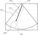
在图4示出三维参考图像72。三维参考图像72有时也被称作体位标志。三维参考图像72将生物体内的三维空间表现为三维图像。作为其表现方式,能举出体绘制法、表面绘制法和其他方式。三维参考图像72具有肿瘤等即靶(靶像)74。另外,三维参考图像72具有第1已有穿刺路径符号(第1已有线)76、第2预定穿刺路径符号(第2预定线)78以及扫描面标志(扫描面符号)77。第1已有穿刺路径符号76基于在第1根穿刺完成的时间点登记的已有穿刺路径来生成。第2预定穿刺路径符号78以三维方式被表现成属于扫描面标志77的面内。第2预定穿刺路径符号78表征从这以后要进行穿刺的穿刺针的穿刺路径。在进行第2根穿刺前,能一边通过参考第1已有穿刺路径符号76来辨识第1根穿刺路径,一边通过参考第2预定穿刺路径符号78来辨识第2根穿刺路径。若变更体表上的探头的位置以及姿势,则与此相伴,扫描面标志77以及第2预定穿刺路径符号78运动。由用户确定探头的位置以及姿势,使得第2预定穿刺路径符号78相对于第1已有穿刺路径符号76成为适合的位置关系。在该情况下,由于与第2预定穿刺路径符号78一起显示扫描面标志77,因此能直观上容易地辨识探头的朝向等。A three-
另外,在三维参考图像72内除了显示靶像74以外还可以显示其他组织,在该情况下,也可以从确保安全性的观点出发显示血管像。在该情况下,可以利用在三维空间内取得的多普勒信息来进行血管的显示。另外,也可以以扫描面标志77为中心定义在其厚度方向上具有一定厚度的近旁空间(观察区),在第1已有穿刺路径属于该近旁空间内的情况下,进行第1已有穿刺路径符号76的高亮显示等。由此,很容易使之前的穿刺路径和今后的穿刺路径两方都属于相同扫描面上。In addition, other tissues other than the
在三维参考图像72的构建时,能在各种方位确定绘制原点(即视点)。该示例以标号80A、80B、80C示出。例如还能如标号80B所示那样,沿着穿刺路径确定视线方向。During the construction of the three-
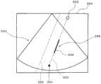
在图5中再次示出图4所示的三维参考图像72。在图5中对与图4所示的构成同样的构成标注相同标号,省略其说明。这在以下说明的各图中也同样。The three-
在图5中,三维参考图像72具有作为靶引导的引导球82。引导球82是具有与靶像74相同尺寸的球体、或是设定在靶像74的外侧的球体。其实体是图形图像。例如在靶像74在三维参考图像72上不清晰的情况下,为了明确显示其边界或形态而期望显示具有与靶相同尺寸的引导球82。或者在必须在靶像74的外侧周围进行多个穿刺针的配置的情况下,为了更易于辨识它们相互的位置关系,期望使比靶像74大的引导球82与它们的中心一致地进行显示。由此,如图示那样,能在三维上直观地辨识各穿刺路径通过引导球82。因而,能容易地掌握它们的位置关系。也可以构成为能由用户任意变更引导球82的尺寸或相对于靶像的比率。另外,也可以显示使中心相同的多重引导球的集合。In Figure 5, the three-
另外,可以在体数据中自动提取靶,基于其来强调显示靶,另外也可以基于其生成引导球。也可以在断层图像上或三维参考图像上由用户确定靶,按照其执行靶自动提取处理。In addition, the target can be automatically extracted from the volume data, the target can be highlighted based on the target, and the guide ball can be generated based on the target. The target can also be determined by the user on the tomographic image or on the three-dimensional reference image, according to which the automatic target extraction process is performed.
在图6中例示进行第1根穿刺前的显示内容。在各个穿刺操作中显示包含图6所示那样的多个导航图像的穿刺辅助图像。具体地,在画面84上,在图示的示例中显示断层图像(超声波断层图像)86、作为第1二维参考图像的同一截面图像88、作为第2二维参考图像的正交截面图像90A以及三维参考图像92。In FIG. 6 , the display content before the first puncture is exemplified. In each puncturing operation, a puncturing assistance image including a plurality of navigation images as shown in FIG. 6 is displayed. Specifically, on the
断层图像86是通过超声波的收发而生成的实时图像。这是表征观察面即扫描面的当前的样子的图像。在断层图像86上将穿刺路径表示为第1预定穿刺路径符号98。其是图形图样。如上述那样,由于探头主体与穿刺适配器的位置关系已知(固定),因此从探头的位置信息能确定三维空间内的第1预定穿刺路径。在图6中,第1预定穿刺路径符号98通过了靶94的一侧周边部分。标号96表示引导圆。引导圆96表征引导球的截面。当然,这样的显示根据需要进行即可。也可以仅显示与现有技术同样的断层图像86。The
同一截面图像88通过从过去取得的体数据取出与扫描面对应的面数据来生成。体数据例如是由CT装置取得的数据,在该情况下,同一截面图像88成为CT断层图像。在同一截面图像88上呈现靶100。将其包围来显示表示引导球的截面的引导圆102。在同一截面图像88上也显示第1预定穿刺路径符号104作为表征穿刺路径的图形要素。在同一截面图像上,其位置不变。若移动探头,则第1预定穿刺路径符号104不动,靶100以及引导圆102的位置发生变化。靶100的中心200在引导球或引导圆的生成阶段由用户指定,或自动检测出。通过这样的动作来确定三维空间内的靶的中心的坐标。The same
在本实施方式中,定义正交截面作为通过中心200且与第1预定穿刺路径正交的面。在同一截面图像88上显示表示正交截面的截面符号(截面线)105。正交截面也被称作C面。In the present embodiment, an orthogonal cross section is defined as a plane passing through the
正交截面图像90A是表征与截面符号对应的正交截面的图像。即,从体数据切出相当于正交截面的面数据,并基于其生成正交截面图像90A。若正交截面随着探头的活动在生物体内运动,则正交截面图像的内容发生变化。标号204表示靶,标号206表示靶的中心,标号202表示作为引导球的截面的引导圆。标号210示出表示扫描面的截面符号(截面线)。截面线210通过中心206。在正交截面图像90A上显示作为第1预定穿刺路径符号的标记208。该标记208具体具有表示特定的坐标的形态,其位于截面线210上,在图示的示例中位于引导圆202的内侧近旁。其表示从这以后要插入的穿刺针的通过位置。也可以如以标号212以及标号214示出的那样,构成为能使作为正交截面显示的区域在上下左右方向上移位。另外,在扫描面即同一截面不通过靶中心的情况下,在正交截面图像90A中,截面线210显示在从中心206移位的位置。The
三维参考图像92是图4以及图5所示的三维参考图像。其具有表征第1根穿刺路径的第1已有穿刺路径符号76和包含第1已有穿刺路径符号76的扫描面标志77。另外,包含作为三维球体的引导球82。引导球82将靶内包。在该示例中,并不是对靶其自身,而是对引导球82确定穿刺路径。The three-
由用户一边参考图6所示的各图像来作为导航图像一边调整探头的位置以及姿势,使得相对于靶或引导球(引导圆),穿刺路径成为适合的位置以及姿势。在探头调整过程中,各个图像被实时更新。但由于体数据是过去取得的数据,因此从那以后生成的参考图像都是表征过去数据的图像。The user adjusts the position and posture of the probe while referring to each of the images shown in FIG. 6 as navigation images so that the puncture path becomes an appropriate position and posture with respect to the target or the guide ball (guide circle). During probe adjustment, individual images are updated in real time. But since the volume data is data acquired in the past, the reference images generated since then are all images that represent the past data.
若通过参考以上那样的多个导航图像而正确地设定了第1预定穿刺路径,就维持探头的位置以及姿势不变地通过穿刺适配器的引导将穿刺针插入到生物体内。穿刺针的插入量能在断层图像上通过目视确定。也可以由传感器自动检测插入量。When the first predetermined puncture route is correctly set by referring to the plurality of navigation images as described above, the puncture needle is inserted into the living body through the guidance of the puncture adapter while maintaining the position and posture of the probe. The insertion amount of the puncture needle can be visually determined on the tomographic image. The insertion amount can also be automatically detected by the sensor.
在图7例示了第1根穿刺完成后的显示内容。这根据针对第1根穿刺的穿刺历史记录登记来显示。在穿刺历史记录登记中,例如登记穿刺针前端的三维坐标,或者登记基于穿刺针的插入量计算的表示穿刺路径的整体的三维坐标信息。FIG. 7 illustrates the display content after the first puncture is completed. This is displayed based on the puncture history registration for the 1st puncture. In the puncture history registration, for example, the three-dimensional coordinates of the distal end of the puncture needle are registered, or the three-dimensional coordinate information representing the entire puncture route calculated based on the insertion amount of the puncture needle is registered.
在断层图像86上呈现第1针像224。穿刺针一般由硬质构件构成,来自那里的回波强,在断层图像86上呈现被插入的针的像。在断层图像86上显示第1已有穿刺路径符号216。具体地,第1已有穿刺路径符号216重叠(合成)显示在B模式断层图像上。第1已有穿刺路径符号216构成为大致线状的图形像,具体地,其包含投影线218(该示例中与后述的交叉线一致)、基端标记220以及前端标记222。投影线218进入到引导圆96的端部,其前端通过靶94的近旁。在断层图像86上,在引导圆96上显示前端标记222。基端标记220是表示穿刺针的基端侧的给定部位的标记。给定部位被确定为穿刺针的尾端、穿刺针中的体表上的位置、穿刺针中的扫描面进入位置等。只要能区别前端侧和基端侧即可,不需要确定成使用户辨识基端的严格位置的程度。前端标记222表征穿刺针的前端的位置、前端部中的电极部中心的位置等。其所示的位置在进行治疗上是重要的。这些标记220、222的样态相互不同,在图示的示例中,基端标记以白的圆来表现,前端标记以黑的圆来表现。这些是例示。也可以使两者的尺寸等不同。The
图7是表示针对第1根穿刺刚刚进行登记后的状态,由于第1已有穿刺路径和第2预定穿刺路径一致,因此仅显示第1已有穿刺路径符号216,而不显示第2预定穿刺路径符号。若移动探头,则第1已有穿刺路径符号的显示位置以及显示方式发生变化(穿刺针像也相同地变化),与其联动地在画面上呈现第2预定穿刺路径符号(其出现位置在图7中与显示第1已有穿刺路径符号的位置相同)。这在图7所示的其他图像88、90A中也同样。在之后说明的图8中示出该状态。另外,若如上述那样移动探头,则在三维参考图像92中,第1已有穿刺路径符号76A不动,扫描面标志77运动,在探头运动开始后,第2预定穿刺路径符号出现。在之后说明的图8中也示出该状态。FIG. 7 shows the state immediately after the registration of the first puncture. Since the first existing puncture route and the second planned puncture route match, only the first existing
在图7中,在同一截面图像88上也显示第1已有穿刺路径符号226。第1已有穿刺路径符号226与已经说明的第1已有穿刺路径符号216同样包含投影线228(与上述同样地,与后述的交叉线一致)、基端标记230以及前端标记232。在同一截面图像88显示已经说明的正交截面线105以及引导圆102。在同一截面图像88上也仍然不显示第2预定穿刺路径符号。In FIG. 7 , the first existing
在正交截面图像90A显示作为标记的第1已有穿刺路径符号234。其是已有穿刺路径向通过靶的中心的正交截面的投影点,同时也是正交截面与第1已有穿刺路径的交叉点。在三维参考图像92也显示表征第1已有穿刺路径的第1已有穿刺路径符号76A。The first existing
在上述说明中,在穿刺完成后的穿刺历史记录登记的时间点,第1预定穿刺路径符号被置换成第1已有穿刺路径符号,之后在移动了探头的时间点,事后显示第2预定穿刺路径符号,但也可以在穿刺历史记录登记的时间点与第1已有穿刺路径符号一起显示第2预定穿刺路径符号。根据本实施方式,能避免两个符号重合显示在相同位置而使两者的识别变得困难的事态。在本实施方式中,例如可以在第1已有穿刺路径与第2预定穿刺路径之间的距离超过给定值的情况下开始第2预定穿刺路径符号的显示。In the above description, at the time of registration of the puncturing history after the puncturing is completed, the symbol of the first planned puncturing route is replaced with the symbol of the first existing puncturing route, and the second planned puncturing is displayed afterwards at the time point when the probe is moved. However, the second planned puncturing route symbol may be displayed together with the first existing puncturing route symbol at the time of puncturing history registration. According to the present embodiment, it is possible to avoid a situation in which two symbols are overlapped and displayed at the same position, making it difficult to recognize both. In the present embodiment, for example, when the distance between the first existing puncturing route and the second planned puncturing route exceeds a predetermined value, the display of the second planned puncturing route symbol may be started.
如以上那样,若正确地插入了第1根穿刺针,就尽可能保持探头的位置以及姿势不变,从穿刺适配器释放第1根穿刺针。之后,为了在体表面上设定第2穿刺路径,再次调整体表面上的探头的位置以及姿势。在该情况下,期望执行使探头保持其姿势不变地在体表上平行移动的操作。As described above, when the first puncture needle is correctly inserted, the first puncture needle is released from the puncture adapter while maintaining the position and posture of the probe as much as possible. After that, in order to set the second puncture route on the body surface, the position and posture of the probe on the body surface are adjusted again. In this case, it is desirable to perform an operation of moving the probe in parallel on the body surface while maintaining its posture.
在图8例示第1根穿刺完成且开始第2根穿刺之前显示的图像的内容。在断层图像86上与第1已有穿刺路径符号216一起显示第2预定穿刺路径符号236。图8所示的第1已有穿刺路径符号216的位置与图7所示的第1已有穿刺路径符号216的位置不同。具体地,在该示例中,前者相当于使后者平行移动后的位置。在扫描面上(准确地说在其近旁空间内)存在第1穿刺针,因此在断层图像86上呈现第1针像224。例如为了在断层图像86上维持第1针像224的显示状态,或为了继续显示第1已有穿刺路径符号216,维持探头的姿势不变地使探头的位置向沿着扫描面的方向移位。其结果,第2预定穿刺路径符号236在第1已有穿刺路径符号216的右侧出现。通过实现两个符号216、236的同时显示,能在确认它们的平行关系的同时并且在确认它们之间的距离的同时适当地事前设定第2个穿刺路径。当然这只是一例,能对应于靶的位置和形状适宜确定第2预定穿刺路径。FIG. 8 illustrates the content of the image displayed before the first puncture is completed and the second puncture is started. The second planned
另外,在本实施方式中,使断层图像86上显示第1已有穿刺路径符号216,但也可以不进行这样的显示。也可以仅显示与现有技术同样的B模式断层图像。在该情况下,也能通过其他多个参考图像准确地设定今后的穿刺路径。也可以仅显示将多个符号合成显示而得的断层图像来作为导航图像。In addition, in the present embodiment, the first existing
在图8中,在同一截面图像88上电显示第1已有穿刺路径符号226和第2预定穿刺路径符号238。第1已有穿刺路径符号226如上述那样包含投影线(交叉线)、前端标志以及基端标志。在本实施方式中,在第1已有穿刺路径的登记时间点,对正交截面进行规定的对象被从第1预定穿刺路径移交到第2预定穿刺路径。即,重新将正交截面定义为通过靶中心且与第2预定穿刺路径正交的截面。In FIG. 8 , the first existing
正交截面图像90A如上述那样是表征正交截面的图像。在正交截面图像90A上分别显示第1已有穿刺路径符号234和第2预定穿刺路径符号240作为标记。第1已有穿刺路径符号234表示正交截面上的第1已有穿刺路径的投影点或交叉点。期望在投影点且交叉点(通过点)的情况下和投影点且非交叉点(非通过点)的情况下,使第1已有穿刺路径符号234的显示方式不同。另外,期望使第1已有穿刺路径符号234的显示方式和第2预定穿刺路径符号240的显示方式不同。在三维参考图像92内显示以三维方式表现的第1已有穿刺路径符号76A以及第2预定穿刺路径符号241。The orthogonal
如以上那样,通过在多个导航图像上显示第1已有穿刺路径符号和第2预定穿刺路径符号,能在对第1已有穿刺路径适当地设定第2预定穿刺路径的基础上,实际执行第2次穿刺。特别,由于使得在显示第1已有路径符号时显示投影线(交叉线)、基端标志以及前端标志,因此在第1已有穿刺路径从观察面即扫描面偏离的情况下,也能得到易于准确地辨识第1已有穿刺路径的空间上的位置的优点。在不显示三维参考图像的情况下,也能得到这样的优点。As described above, by displaying the first existing puncturing route symbol and the second planned puncturing route symbol on the plurality of navigation images, it is possible to set the second planned puncturing route appropriately for the first existing puncturing route. Perform a second puncture. In particular, since the projection line (cross line), the base end mark, and the distal end mark are displayed when the first existing path symbol is displayed, even when the first existing puncture path deviates from the observation plane, that is, the scanning plane, it is possible to obtain There is an advantage that the spatial position of the first existing puncture path can be easily and accurately recognized. This advantage can also be obtained without displaying a three-dimensional reference image.
在图9例示第2根穿刺完成的时间点的显示内容。在断层图像86上显示第1已有穿刺路径符号216和第2已有穿刺路径符号242。即,在三维空间内,夹着靶地平行插入2根穿刺针。两者的插入量大致相同。第1已有穿刺路径符号216包含投影线(交叉线)、前端标记以及基端标记。在那里还显示第1针像224。相同地,第2已有穿刺路径符号242包含投影线(交叉线)244、前端标记248以及基端标记246。在那里还显示第2针像250。FIG. 9 illustrates the display contents at the time point when the second puncture is completed. The first existing
在同一截面图像88上也显示第1已有穿刺路径符号226以及第2已有穿刺路径符号252。第2已有穿刺路径符号252与第1已有穿刺路径符号同样包含投影线(交叉线)253、前端标记256以及基端标记254。The first existing
在正交截面图像90A上,在引导圆202上显示第1已有穿刺路径符号234以及第2已有穿刺路径符号258。在三维参考图像92中包含第1已有穿刺路径符号76A和第2实际结果穿刺路径符号259。On the orthogonal
在相对于靶正确地对两个穿刺针确定位置后,将第2根穿刺针从穿刺适配器释放。之后,对靶执行烧灼治疗。之后,可以通过超声波诊断来观察靶的状态。在烧灼治疗执行后,将两个穿刺针从生物体拔出。After both puncture needles are correctly positioned relative to the target, the second puncture needle is released from the puncture adapter. Afterwards, a cautery treatment is performed on the target. After that, the state of the target can be observed by ultrasound diagnosis. After the cautery treatment is performed, the two puncture needles are withdrawn from the living body.
在上述实施方式中示出了两根穿刺针的插入,但在插入三根以上的穿刺针的情况下也执行与上述同样的处理。以上说明的构成都是例示,能对应于治疗目的、治疗条件、用户的需求等适宜变更。In the above-described embodiment, the insertion of two puncture needles is shown, but the same processing as above is performed also when three or more puncture needles are inserted. The configurations described above are all examples, and can be appropriately changed according to the purpose of treatment, treatment conditions, and needs of the user.
本实施方式的超声波诊断系统将上述的已有穿刺路径符号的显示方式(作为投影像的投影线、作为交叉像的交叉线等)作为特征事项。以下,使用图10到图17来详细说明其显示。The ultrasonic diagnostic system of the present embodiment features the above-described display method of the existing puncture path symbols (projection lines as projected images, intersection lines as intersecting images, etc.). Hereinafter, the display will be described in detail using FIGS. 10 to 17 .
在观察面是扫描面的情况下,预定穿刺路径始终属于观察面上。这是因为,穿刺适配器以满足这样的条件的方式来规定穿刺路径。因而,在断层图像上以及同一截面图像上基本始终显示预定穿刺路径符号的全部。另一方面,已有穿刺路径全部都属于观察面(扫描面)仅是探头的位置以及姿势与某特定的条件相符合的情况。因而,在不花费特别的工夫而要在断层图像上以及同一截面图像上原样不变地显示已有穿刺路径的情况下,若已有穿刺路径不与扫描面交叉,就完全不显示已有穿刺路径,或者若已有穿刺路径与扫描面交叉,则已有穿刺路径就显示成单纯的交叉点。在这样的显示方式中,辨识已有穿刺路径与扫描面的空间上的关系变得困难。因此,在本实施方式中,在显示已有穿刺路径时,显示其向观察面的投影像。在观察面不是扫描面的情况下,也可以将预定穿刺路径显示为投影像。When the observation plane is the scanning plane, the predetermined puncturing path always belongs to the observation plane. This is because the puncture adapter defines the puncture route so as to satisfy such conditions. Therefore, almost all of the predetermined puncture path symbols are displayed on the tomographic image and on the same cross-sectional image. On the other hand, all existing puncture routes belong to the observation plane (scanning plane) only when the position and posture of the probe meet certain specific conditions. Therefore, when the existing puncture route is to be displayed as it is on the tomographic image and the same cross-sectional image without any special effort, the existing puncture route is not displayed at all unless the existing puncture route intersects the scanning plane. path, or if an existing puncture path intersects the scan plane, the existing puncture path is displayed as a simple intersection. In such a display method, it becomes difficult to recognize the spatial relationship between the existing puncture path and the scanning surface. Therefore, in the present embodiment, when displaying the existing puncture route, the projection image of the puncturing route on the observation surface is displayed. When the observation plane is not the scanning plane, the predetermined puncturing route may be displayed as a projection image.
在图10中示出三维空间。在其中包含作为扫描面的观察面262。对观察面262给出假想的厚度,通过该厚度来定义板状的观察区264。厚度方向的中心是观察面262。在观察面262的前后分别存在半区。厚度的大小由用户设定,或者按照某些参数自动设定。期望对应于治疗状况或治疗条件使厚度可变。A three-dimensional space is shown in FIG. 10 . The
在三维空间260内存在穿刺路径(具体为已有穿刺路径)266。在图示的示例中,穿刺路径266贯通观察面262。穿刺路径是基端270与前端272之间的直线路径。通过将穿刺路径266投影到观察面262上来定义投影像274。投影像被显示为线状的图形图样即投影线。从基端270向观察面262上拉垂线,观察面262与垂线相交的点是投影像274的基端。该基端由基端标记278表现。从前端272向观察面262上拉垂线,观察面262与垂线相交的点是投影像274的前端。该前端由前端标记280表现。基端标记278和前端标记280以相互不同的显示方式显示。在图示的示例中,基端标记278是白色的圆,前端标记280是黑色的圆。当然,这些显示方式是一例。A puncture path (specifically, an existing puncture path) 266 exists in the three-
在穿刺路径266内,与观察区264交叉(被包含)的部分是线段268。在图10中线段268表现为粗的线。即使穿刺路径266与观察面262的位置关系不变,线段268的尺寸也会因厚度的大小而变化。将线段268通过与上述同样的手法投影到观察面262上得到的像是交叉像276。其显示为交叉线。在图10中,交叉像276表现为粗的线。交叉像276其自身也是投影像,存在于先前说明的投影像274上。显示交叉像276的情况仅是穿刺路径266与观察区264交叉的情况。在未发生交叉的情况下,即使显示投影像274,也不显示交叉像276。更详细来说,在发生了交叉的情况下,交叉像276显示在投影像274的两端间,交叉像276具有投影像274的长度以下的长度。若穿刺路径266的位置相对于观察面262发生变化,则投影像274的位置以及长度会随之变化,并且交叉像276的位置以及长度会随之变化。在交叉像276的变化中包含交叉像276消失。Within
在本实施方式中,作为图7到图9所示的已有穿刺路径符号,上述那样的投影像274显示为投影线。具体地,在已有穿刺路径符号中除了包含投影像274以外,还包含基端标记278以及前端标记280,进而在发生交叉的情况下包含作为交叉线的交叉像276。此外,如后述那样,在表现相对于观察面262的交叉(贯通)朝向的情况下,在已有穿刺路径符号中还包含给定的指示器群。根据这样的已有穿刺路径符号的显示,即使穿刺路径相对于观察面在1点交叉,或者不发生交叉其自身,也能大致辨识观察面与穿刺路径的空间上的关系。In the present embodiment, the above-described projected
在图11示出观察区264的截面。该截面是穿刺路径266中的线段所属的面。穿刺路径266相对于观察面的法线以角度θ相交。相对于观察区264的厚度d,交叉像的长度L例如以L=d·tanθ计算。若使d的大小变化,则L的大小也变化。期望考虑切片厚度、位置确定精度、位置确定容易性等来可变地设定d的大小。A cross-section of
在图12示出已有穿刺路径符号的第1显示例。在同一截面图像330上与虚线状的预定穿刺路径符号292一起显示已有穿刺路径符号332。已有穿刺路径符号332由虚线状的投影线274、白的圆形的基端标记278、黑的圆形的前端标记280、以及粗的实线状的交叉线276构成。交叉线276重叠显示于投影线274上。也可以将投影线274中的相当于交叉线276的部分设为非显示。即,可以仅生成实际能视觉辨识的部分作为投影线274。在该示例中,基端标记278属于同一截面图像内。对于引导圆图示省略。期望上述那样的已有穿刺路径符号进一步也显示在断层图像上以及正交截面图像上。在已有穿刺路径与观察面正交的情况下,投影像例如成为圆以及点中的一者,在已有穿刺路径与观察面正交且交叉的情况下,交叉像例如成为圆以及点中的另一者。在正交截面图像上显示已有穿刺路径符号的情况下,正交截面被作为观察面,以正交截面为基准来计算投影像以及交叉像。FIG. 12 shows a first display example of the existing puncture path symbol. The existing
若在第2根穿刺之前使探头的位置以及姿势变化,则在同一截面图像上,预定穿刺路径符号的显示方式不变,已有穿刺路径符号的显示方式动态地变化。例如在希望相对于已有穿刺路径平行地设定预定穿刺路径的情况下,调整探头的位置以及姿势,使得在同一截面图像上,已有穿刺路径符号相对于预定穿刺路径符号空开给定的间隔平行,具体地,使得在已有穿刺路径符号处交叉线与投影线一致。另外,从穿刺适配器侧来看的预定穿刺路径与已有穿刺路径的位置关系通常能在正交截面图像上容易地辨识。在正交截面图像上,若已有穿刺路径不是显示为线状,而是显示为点或圆的像,则已有穿刺路径就会相对于正交截面正确地正交。在第3根以后的穿刺中也同样。在第3根以后的穿刺中,在同时观察多个穿刺路径时,正交截面图像以及三维图像是有用的。If the position and posture of the probe are changed before the second puncture, on the same cross-sectional image, the display format of the symbol of the planned puncture route does not change, and the display format of the symbol of the existing puncture route changes dynamically. For example, when it is desired to set the predetermined puncture path in parallel with the existing puncture path, adjust the position and posture of the probe so that on the same cross-sectional image, the existing puncture path symbol is spaced apart from the predetermined puncture path symbol by a given amount. The spacing is parallel, in particular, so that the intersecting lines coincide with the projected lines at the existing puncture path symbols. In addition, the positional relationship between the predetermined puncture route and the existing puncture route seen from the puncture adapter side can usually be easily recognized on the orthogonal cross-sectional image. On the orthogonal cross-section image, if the existing puncture path is not displayed as a line but as a dot or circle image, the existing puncture path will be correctly orthogonal to the orthogonal cross-section. The same applies to the third and subsequent punctures. In the third and subsequent puncture, the orthogonal cross-sectional image and the three-dimensional image are useful when simultaneously observing a plurality of puncture paths.
在图13中示出已有穿刺路径符号的第2显示例。在同一截面图像330上与预定穿刺路径符号292一起显示已有穿刺路径符号332。在已有穿刺路径符号332处,投影线与交叉线一致(参考标号276)。因此,基端标记278与前端标记280之间全部都显示为粗的线。这意味着已有穿刺路径属于观察区(以扫描面为基准的一定的厚度范围)。基端标记278在该示例中存在于同一截面图像(扫描面)的边缘上。FIG. 13 shows a second display example of the existing puncture path symbol. The existing
在图14示出已有穿刺路径符号的第3显示例。在同一截面图像330上与预定穿刺路径符号292一起显示已有穿刺路径符号332。在已有穿刺路径符号332处,投影线的显示坐标和交叉线的显示坐标一致,例如投影线以圆来表现,交叉像以点进行显示。在图14所示的显示方式中不显示基端标记以及前端标记。也能理解为,上述的圆以及点是它们的标记。在已有穿刺路径相对于观察区不交叉的情况下,不显示交叉像。即,图14所示的方式表征已有穿刺路径相对于观察面完全正交。FIG. 14 shows a third display example of the existing puncture path symbol. The existing
在图15示出已有穿刺路径符号的第4显示例。在同一截面图像330上与预定穿刺路径符号296一起显示已有穿刺路径符号298。已有穿刺路径符号298包含虚线状的投影线300、粗的实线状的交叉线306、以大的白的圆表现的基端标记302以及以小的黑的圆表现的前端标记304。在该示例中,基端标记显示在同一截面图像(扫描面)的外部。预定穿刺路径符号296其两端从同一截面图像(扫描面)伸出。FIG. 15 shows a fourth display example of the existing puncture path symbol. The existing
在显示图7到图9所示的断层图像、同一截面图像以及正交截面图像时,期望显示以上那样的已有穿刺路径符号。When displaying the tomographic images, the same cross-sectional images, and the orthogonal cross-sectional images shown in FIGS. 7 to 9 , it is desirable to display the existing puncture path symbols as described above.
在图16示出针对已有穿刺路径符号的其他显示形态。已有穿刺路径符号308包含投影像310、交叉像316、基端标记318以及前端标记320。投影像310在图示的示例中包含线状的两个指示器312、314。例如各指示器312、314由多个三角形要素构成。各个要素的朝向(尖塔形所朝向的方向)表示穿刺方向。指示器312的显示方式(例如颜色)表示从基端到交叉部分的区间是位于观察区的进深侧(背侧、一侧)还是位于近前侧(表侧、另一侧)。相同地,指示器314的显示方式(例如颜色)表示从基端到交叉部分的区间是位于观察区的近前侧(表侧、另一侧)还是位于进深侧(背侧、一侧)。例如第1颜色(例如灰色)表示进深侧,第2颜色(例如白色)表示近前侧。在发生交叉的情况下,基本上两个指示器312、314中的一方以第1颜色表现为进深侧指示器,另一方以第2颜色表现为前侧指示器。在确定前后时,可以以图4所示的视点为基准。方向的识别例如由图1所示的控制部完成。但在交叉像到达基端或前端的情况下,也有时不显示任一个指示器。FIG. 16 shows another display form for existing puncture path symbols. The existing
可以对应于已有穿刺路径向观察面的交叉角度的大小来使两个指示器312、314的显示方式变化。例如可以按照图17所示那样的条件使要素间间距变化。观察区264通过对观察面给出一定的厚度来定义。作为相对于观察面的正交方向来定义法线334。角度θ是穿刺路径266与法线334所成的角度。在将采用的要素间间距设为D,将其初始值设为C的情况下,例如可以通过R=C*sinθ来确定要素间间距D。构成各个两个指示器312、314的要素数可以根据投影线中的存在于交叉线的两侧的两个区间的大小和上述那样计算出的要素间间距D来决定。The display modes of the two
如以上那样,通过包含指示器作为投影像的一部分,或者在投影像附加指示器,能直观且容易地辨识穿刺路径是从观察面的进深侧向近前侧穿透,还是从近前侧向进深侧穿透。上述的说明中出现的各个计算式是例示。As described above, by including an indicator as a part of the projected image or by adding an indicator to the projected image, it is possible to intuitively and easily recognize whether the puncture path penetrates from the deep side to the near side of the observation surface, or from the near side to the deep side penetrate. The respective calculation expressions appearing in the above description are examples.
另外,在显示正交截面图像等时,可以显示针对各个穿刺路径的坐标信息,另外也可以显示穿刺路径间的距离信息。In addition, when displaying an orthogonal cross-sectional image or the like, the coordinate information for each puncture path may be displayed, and the distance information between the puncture paths may be displayed.
Claims (8)
Applications Claiming Priority (3)
| Application Number | Priority Date | Filing Date | Title |
|---|---|---|---|
| JP2015203447AJP6078134B1 (en) | 2015-10-15 | 2015-10-15 | Medical system |
| JP2015-203447 | 2015-10-15 | ||
| PCT/JP2016/080252WO2017065173A1 (en) | 2015-10-15 | 2016-10-12 | Medical treatment system |
Publications (2)
| Publication Number | Publication Date |
|---|---|
| CN108135577A CN108135577A (en) | 2018-06-08 |
| CN108135577Btrue CN108135577B (en) | 2020-08-04 |
Family
ID=57981634
Family Applications (1)
| Application Number | Title | Priority Date | Filing Date |
|---|---|---|---|
| CN201680056027.XAActiveCN108135577B (en) | 2015-10-15 | 2016-10-12 | Medical system |
Country Status (3)
| Country | Link |
|---|---|
| JP (1) | JP6078134B1 (en) |
| CN (1) | CN108135577B (en) |
| WO (1) | WO2017065173A1 (en) |
Families Citing this family (4)
| Publication number | Priority date | Publication date | Assignee | Title |
|---|---|---|---|---|
| JP7355514B2 (en)* | 2019-03-28 | 2023-10-03 | ザイオソフト株式会社 | Medical image processing device, medical image processing method, and medical image processing program |
| JP7440328B2 (en) | 2020-04-03 | 2024-02-28 | キヤノンメディカルシステムズ株式会社 | Ultrasound diagnostic equipment and programs |
| EP3895645A1 (en)* | 2020-04-14 | 2021-10-20 | Koninklijke Philips N.V. | Ablation planning system |
| WO2023101707A1 (en)* | 2021-12-02 | 2023-06-08 | Poplaw Steven | System for color-coding medical instrumentation and methods of use |
Citations (6)
| Publication number | Priority date | Publication date | Assignee | Title |
|---|---|---|---|---|
| US6423009B1 (en)* | 1996-11-29 | 2002-07-23 | Life Imaging Systems, Inc. | System, employing three-dimensional ultrasonographic imaging, for assisting in guiding and placing medical instruments |
| CN103635143A (en)* | 2012-06-29 | 2014-03-12 | 株式会社东芝 | Diagnostic ultrasound apparatus and ultrasound image processing method |
| CN103987324A (en)* | 2012-11-09 | 2014-08-13 | 株式会社东芝 | piercing aid |
| JP2014161444A (en)* | 2013-02-22 | 2014-09-08 | Toshiba Corp | Ultrasound diagnostic device, medical image processor and control program |
| JP2015013069A (en)* | 2013-07-08 | 2015-01-22 | ジーイー・メディカル・システムズ・グローバル・テクノロジー・カンパニー・エルエルシー | Ultrasonic diagnostic apparatus and control program thereof |
| JP2015173843A (en)* | 2014-03-17 | 2015-10-05 | 富士フイルム株式会社 | MEDICAL IMAGE DISPLAY DEVICE, METHOD, AND PROGRAM |
- 2015
- 2015-10-15JPJP2015203447Apatent/JP6078134B1/enactiveActive
- 2016
- 2016-10-12CNCN201680056027.XApatent/CN108135577B/enactiveActive
- 2016-10-12WOPCT/JP2016/080252patent/WO2017065173A1/ennot_activeCeased
Patent Citations (6)
| Publication number | Priority date | Publication date | Assignee | Title |
|---|---|---|---|---|
| US6423009B1 (en)* | 1996-11-29 | 2002-07-23 | Life Imaging Systems, Inc. | System, employing three-dimensional ultrasonographic imaging, for assisting in guiding and placing medical instruments |
| CN103635143A (en)* | 2012-06-29 | 2014-03-12 | 株式会社东芝 | Diagnostic ultrasound apparatus and ultrasound image processing method |
| CN103987324A (en)* | 2012-11-09 | 2014-08-13 | 株式会社东芝 | piercing aid |
| JP2014161444A (en)* | 2013-02-22 | 2014-09-08 | Toshiba Corp | Ultrasound diagnostic device, medical image processor and control program |
| JP2015013069A (en)* | 2013-07-08 | 2015-01-22 | ジーイー・メディカル・システムズ・グローバル・テクノロジー・カンパニー・エルエルシー | Ultrasonic diagnostic apparatus and control program thereof |
| JP2015173843A (en)* | 2014-03-17 | 2015-10-05 | 富士フイルム株式会社 | MEDICAL IMAGE DISPLAY DEVICE, METHOD, AND PROGRAM |
Also Published As
| Publication number | Publication date |
|---|---|
| JP6078134B1 (en) | 2017-02-08 |
| CN108135577A (en) | 2018-06-08 |
| JP2017074221A (en) | 2017-04-20 |
| WO2017065173A1 (en) | 2017-04-20 |
Similar Documents
| Publication | Publication Date | Title |
|---|---|---|
| CN106456135B (en) | medical system | |
| US20230233264A1 (en) | Systems, methods, apparatuses, and computer-readable media for image management in image-guided medical procedures | |
| US11464575B2 (en) | Systems, methods, apparatuses, and computer-readable media for image guided surgery | |
| US8556815B2 (en) | Freehand ultrasound imaging systems and methods for guiding fine elongate instruments | |
| JP5775164B2 (en) | Ultrasonic diagnostic apparatus and ultrasonic image display method | |
| US8696582B2 (en) | Apparatus and method for imaging a medical instrument | |
| US8670816B2 (en) | Multiple medical device guidance | |
| US20170095226A1 (en) | Ultrasonic diagnostic apparatus and medical image diagnostic apparatus | |
| CN112533540B (en) | Ultrasonic imaging method, ultrasonic imaging device and puncture navigation system | |
| JP5889095B2 (en) | Puncture planning support apparatus, medical image apparatus, and ultrasonic diagnostic apparatus | |
| JP2007000226A (en) | Medical diagnostic imaging equipment | |
| JP2014028125A (en) | Ultrasonic diagnostic apparatus and control program | |
| CN108135577B (en) | Medical system | |
| WO2017106748A1 (en) | Needle tracking transducer array methods and apparatus | |
| US10238363B2 (en) | Needle guide for ultrasound transducer | |
| US20140316272A1 (en) | Ultrasound diagnosis apparatus | |
| CN116458974A (en) | Ultrasonic guided puncture system, control method thereof, electronic device and storage medium | |
| CN219126680U (en) | Interventional operation device for laser radar navigation | |
| JP2020185040A (en) | Medical imaging device | |
| CN118236128A (en) | Interventional operation device for laser radar navigation |
Legal Events
| Date | Code | Title | Description |
|---|---|---|---|
| PB01 | Publication | ||
| PB01 | Publication | ||
| SE01 | Entry into force of request for substantive examination | ||
| SE01 | Entry into force of request for substantive examination | ||
| GR01 | Patent grant | ||
| GR01 | Patent grant | ||
| TR01 | Transfer of patent right | Effective date of registration:20220216 Address after:Chiba County, Japan Patentee after:Fujifilm medical health Co.,Ltd. Patentee after:NATIONAL UNIVERSITY CORPORATION EHIME University Patentee after:JAPAN RED CROSS Address before:Tokyo, Japan Patentee before:Hitachi, Ltd. Patentee before:NATIONAL UNIVERSITY CORPORATION EHIME University Patentee before:JAPAN RED CROSS | |
| TR01 | Transfer of patent right | ||
| TR01 | Transfer of patent right | Effective date of registration:20241209 Address after:Japan Patentee after:FUJIFILM Corp. Country or region after:Japan Patentee after:NATIONAL UNIVERSITY CORPORATION EHIME University Patentee after:JAPAN RED CROSS Address before:Chiba County, Japan Patentee before:Fujifilm medical health Co.,Ltd. Country or region before:Japan Patentee before:NATIONAL UNIVERSITY CORPORATION EHIME University Patentee before:JAPAN RED CROSS | |
| TR01 | Transfer of patent right |