CN108095806B - Adsorption puncture fixing device with self-locking function - Google Patents
Adsorption puncture fixing device with self-locking functionDownload PDFInfo
- Publication number
- CN108095806B CN108095806BCN201711356845.4ACN201711356845ACN108095806BCN 108095806 BCN108095806 BCN 108095806BCN 201711356845 ACN201711356845 ACN 201711356845ACN 108095806 BCN108095806 BCN 108095806B
- Authority
- CN
- China
- Prior art keywords
- clamping arm
- self
- puncture
- hinge point
- fixing device
- Prior art date
- Legal status (The legal status is an assumption and is not a legal conclusion. Google has not performed a legal analysis and makes no representation as to the accuracy of the status listed.)
- Active
Links
- 238000001179sorption measurementMethods0.000titleclaimsabstractdescription25
- 239000002775capsuleSubstances0.000claimsabstractdescription27
- 210000004400mucous membraneAnatomy0.000claimsabstractdescription20
- 238000005452bendingMethods0.000claimsdescription19
- 238000010521absorption reactionMethods0.000claimsdescription6
- 230000000149penetrating effectEffects0.000claims3
- 238000000034methodMethods0.000description6
- 210000004877mucosaAnatomy0.000description6
- 210000003238esophagusAnatomy0.000description5
- 208000021302gastroesophageal reflux diseaseDiseases0.000description5
- 208000000689peptic esophagitisDiseases0.000description5
- 230000004308accommodationEffects0.000description3
- 238000006243chemical reactionMethods0.000description2
- 239000003814drugSubstances0.000description2
- 230000000694effectsEffects0.000description2
- 238000007689inspectionMethods0.000description2
- 206010063655Erosive oesophagitisDiseases0.000description1
- 208000008589ObesityDiseases0.000description1
- 206010030201Oesophageal ulcerDiseases0.000description1
- 230000035622drinkingEffects0.000description1
- 230000002183duodenal effectEffects0.000description1
- 208000028299esophageal diseaseDiseases0.000description1
- 208000019064esophageal ulcerDiseases0.000description1
- 230000002496gastric effectEffects0.000description1
- 230000002757inflammatory effectEffects0.000description1
- 230000003902lesionEffects0.000description1
- 230000014759maintenance of locationEffects0.000description1
- 230000003340mental effectEffects0.000description1
- 238000012986modificationMethods0.000description1
- 230000004048modificationEffects0.000description1
- 235000020824obesityNutrition0.000description1
- 238000010992refluxMethods0.000description1
- 230000000391smoking effectEffects0.000description1
- 239000013589supplementSubstances0.000description1
Images


Classifications
- A—HUMAN NECESSITIES
- A61—MEDICAL OR VETERINARY SCIENCE; HYGIENE
- A61B—DIAGNOSIS; SURGERY; IDENTIFICATION
- A61B17/00—Surgical instruments, devices or methods
- A61B17/34—Trocars; Puncturing needles
- A61B17/3403—Needle locating or guiding means
- A—HUMAN NECESSITIES
- A61—MEDICAL OR VETERINARY SCIENCE; HYGIENE
- A61B—DIAGNOSIS; SURGERY; IDENTIFICATION
- A61B17/00—Surgical instruments, devices or methods
- A61B17/34—Trocars; Puncturing needles
- A61B17/3468—Trocars; Puncturing needles for implanting or removing devices, e.g. prostheses, implants, seeds, wires
- A—HUMAN NECESSITIES
- A61—MEDICAL OR VETERINARY SCIENCE; HYGIENE
- A61B—DIAGNOSIS; SURGERY; IDENTIFICATION
- A61B17/00—Surgical instruments, devices or methods
- A61B17/34—Trocars; Puncturing needles
- A61B17/3403—Needle locating or guiding means
- A61B2017/3405—Needle locating or guiding means using mechanical guide means
- A—HUMAN NECESSITIES
- A61—MEDICAL OR VETERINARY SCIENCE; HYGIENE
- A61B—DIAGNOSIS; SURGERY; IDENTIFICATION
- A61B17/00—Surgical instruments, devices or methods
- A61B17/34—Trocars; Puncturing needles
- A61B2017/347—Locking means, e.g. for locking instrument in cannula
Landscapes
- Health & Medical Sciences (AREA)
- Surgery (AREA)
- Life Sciences & Earth Sciences (AREA)
- Medical Informatics (AREA)
- Nuclear Medicine, Radiotherapy & Molecular Imaging (AREA)
- Engineering & Computer Science (AREA)
- Biomedical Technology (AREA)
- Heart & Thoracic Surgery (AREA)
- Pathology (AREA)
- Molecular Biology (AREA)
- Animal Behavior & Ethology (AREA)
- General Health & Medical Sciences (AREA)
- Public Health (AREA)
- Veterinary Medicine (AREA)
- External Artificial Organs (AREA)
- Surgical Instruments (AREA)
Abstract
Description
Translated fromChinese技术领域technical field
本发明属于医疗器械技术领域,涉及一种带自锁功能的吸附穿刺固定装置。The invention belongs to the technical field of medical devices, and relates to an adsorption puncture fixing device with a self-locking function.
背景技术Background technique
反流性食管炎(RE)是由胃、十二指肠内容物反流入食管引起的食管炎症性病变,内镜下表现为食管黏膜的破损,即食管糜烂和(或)食管溃疡。反流性食管炎可发生于任何年龄的人群,成人发病率随年龄增长而升高。近二十年全球的发病率都有上升趋势。中老年人、肥胖、吸烟、饮酒及精神压力大是反流性食管炎的高发人群。治疗反流性食管炎的方法,通常都是采用食用药物或将pH胶囊固定到人体食道中的治疗方式,直接将pH胶囊固定到人体食道中的治疗方法要比食用药物的疗效更好。Reflux esophagitis (RE) is an inflammatory lesion of the esophagus caused by the reflux of gastric and duodenal contents into the esophagus. Endoscopically, the damage of the esophageal mucosa is manifested as esophageal erosion and/or esophageal ulcer. Reflux esophagitis can occur in people of any age, and the incidence in adults increases with age. The global incidence rate has been on the rise in the past two decades. Middle-aged and elderly people, obesity, smoking, drinking, and high mental stress are high-risk groups for reflux esophagitis. The method of treating reflux esophagitis usually adopts the treatment method of taking medicine or fixing the pH capsule in the human esophagus, and the treatment method of directly fixing the pH capsule in the human esophagus is better than taking medicine.
目前,通常采用吸附穿刺固定装置将pH胶囊固定在人体食道内,其通过负压将人体黏膜吸附到pH胶囊内,吸附穿刺固定装置的穿刺针刺入到人体黏膜实现固定。现有的吸附穿刺固定装置位于pH胶囊内,从外表无法判定其是否合格有效,只能在使用前对其进行品质检验,但吸附穿刺固定装置只能一次性使用,在品质检验时一旦动作完成后,就没有再次穿刺的力量,无法恢复到穿刺成功后的极限位置,使固定装置提前从人体黏膜组织上脱落。而且现有的固定装置内设有两个旋转臂,结构复杂。At present, the pH capsule is usually fixed in the human esophagus by an adsorption puncture fixation device, which absorbs the human mucosa into the pH capsule through negative pressure, and the puncture needle of the adsorption puncture fixation device penetrates into the human mucosa to achieve fixation. The existing adsorption and puncture fixing device is located in the pH capsule, and it is impossible to judge whether it is qualified and effective from the outside. It can only be inspected for quality before use. However, the adsorption and puncture fixing device can only be used once. Once the action is completed during the quality inspection After that, there is no power to puncture again, and it cannot be restored to the limit position after successful puncture, so that the fixing device falls off from the human mucosal tissue in advance. Moreover, two rotating arms are arranged in the existing fixing device, and the structure is complex.
发明内容Contents of the invention
本发明的目的是针对现有的技术存在上述问题,提出了一种穿刺力量不会变小的带自锁功能的吸附穿刺固定装置。The object of the present invention is to solve the above-mentioned problems in the prior art, and propose an adsorption puncture fixing device with self-locking function that does not reduce the puncture force.
本发明的目的可通过下列技术方案来实现:The purpose of the present invention can be achieved through the following technical solutions:
带自锁功能的吸附穿刺固定装置,设于pH胶囊内,pH胶囊上设有负压吸入孔,负压吸入孔的侧部具有与负压吸入孔连通的容纳腔,其特征在于,吸附穿刺固定装置包括设于容纳腔内的旋转轴、套设在旋转轴上的夹持臂和用于驱动夹持臂绕旋转轴由初始状态旋转至工作状态的驱动件,所述的夹持臂上具有初始状态位于容纳腔内的旋转穿刺针,当夹持臂处于工作状态时旋转穿刺针伸入至负压吸入孔内,pH胶囊与夹持臂之间设有自锁组件。The adsorption puncture fixing device with self-locking function is set in the pH capsule, and the pH capsule is provided with a negative pressure suction hole. The fixing device includes a rotating shaft arranged in the accommodating chamber, a clamping arm sleeved on the rotating shaft, and a driving member for driving the clamping arm to rotate from the initial state to the working state around the rotating shaft. It has a rotating puncture needle located in the receiving chamber in the initial state, and when the clamping arm is in the working state, the rotating puncture needle extends into the negative pressure suction hole, and a self-locking component is arranged between the pH capsule and the clamping arm.
当夹持臂处于初始状态时,在自锁组件的作用下,夹持臂实现自锁;当夹持臂处于工作状态,在自锁组件的作用下,夹持臂也能实现自锁。When the clamping arm is in the initial state, the clamping arm can realize self-locking under the action of the self-locking component; when the clamping arm is in the working state, the clamping arm can also realize self-locking under the action of the self-locking component.
在上述的带自锁功能的吸附穿刺固定装置中,所述的自锁组件包括一具有弹力的弹性件,所述的容纳腔的内壁上具有铰接点一,所述的夹持臂上具有铰接点二,所述弹性件的一端铰接在铰接点一处,另一端铰接在铰接点二处,当夹持臂处于初始状态时铰接点二位于铰接点一与旋转轴垂直连线的一侧,当夹持臂处于工作状态时铰接点二位于铰接点一与旋转轴垂直连线的另一侧。In the above-mentioned absorption puncture fixing device with self-locking function, the self-locking component includes an elastic member with elastic force, the inner wall of the accommodating cavity has a hinge point one, and the clamping arm has a
当夹持臂处于初始状态时,弹性件施加在夹持臂上的弹力可使夹持臂保持在初始状态位置。当人体黏膜组织被吸入到负压吸入孔内后,驱动件开始工作,驱动件作用在夹持臂上的力大于弹性件作用在夹持臂上的力,驱动夹持臂绕旋转轴旋转,在旋转的过程中,弹性件的弹力逐渐增大,当旋转轴、铰接点二和铰接点一三点共线时,弹性件的弹力达到最大。驱动件继续驱动,铰接点二越过铰接点一与旋转轴的垂直连线后进入到另一侧,弹性件的弹力施加在夹持臂上使夹持臂向工作状态方向旋转,当夹持臂完全处于工作状态时,弹性件使夹持臂保持在工作状态位置,在没有外力作用下,旋转臂不会回退。When the clamping arm is in the initial state, the elastic force exerted by the elastic member on the clamping arm can keep the clamping arm in the initial state. When the human mucous membrane tissue is sucked into the negative pressure suction hole, the driving part starts to work, the force of the driving part on the clamping arm is greater than the force of the elastic part on the clamping arm, and the clamping arm is driven to rotate around the rotation axis. During the rotation process, the elastic force of the elastic member gradually increases, and when the rotation axis, the second hinge point and the first hinge point three points are collinear, the elastic force of the elastic member reaches the maximum. The driving part continues to drive, and the
当pH胶囊从人体黏膜组织上脱落后,用镊子扳动弹性件,使弹性件由铰接点一与旋转轴垂直连线的另一侧复位至铰接点一与旋转轴垂直连线的一侧,便于pH胶囊的再次使用。When the pH capsule falls off from the human mucous membrane tissue, use tweezers to pull the elastic part, so that the elastic part is reset from the other side of the hinge point perpendicular to the axis of rotation to the side of the hinge point perpendicular to the axis of rotation. Easy re-use of pH capsules.
在上述的带自锁功能的吸附穿刺固定装置中,所述的旋转轴平行于负压吸入孔的轴线设置,所述的旋转穿刺针位于夹持臂远离旋转轴的一端处且所述的夹持臂沿其旋转方向弧形延伸。In the above-mentioned absorption puncture fixing device with self-locking function, the rotating shaft is arranged parallel to the axis of the negative pressure suction hole, the rotating puncture needle is located at the end of the clamping arm away from the rotating shaft and the clamping The holding arm extends in an arc along its direction of rotation.
在上述的带自锁功能的吸附穿刺固定装置中,所述的弹性件为扭簧,所述的夹持臂上具有与旋转轴平行的连接孔一,所述扭簧的一端具有伸入至连接孔一内的弯折部一,所述的弯折部一上具有限位部。扭簧转动时以弯折部一的中轴线为旋转中心,因此铰接点二位于弯折部一的中轴线上。In the above-mentioned absorption puncture fixing device with self-locking function, the elastic member is a torsion spring, the clamping arm has a connection hole I parallel to the rotation axis, and one end of the torsion spring has a The
在上述的带自锁功能的吸附穿刺固定装置中,所述的容纳腔远离负压吸入孔的一侧上具有限位凹槽,所述的限位凹槽上具有与旋转轴平行的连接孔二,所述扭簧的另一端具有伸入至连接孔二内的弯折部二。扭簧同时以弯折部二的中轴线为旋转中心,铰接点二位于弯折部二的中轴线上。In the aforementioned self-locking adsorption puncture fixing device, the side of the accommodating cavity away from the negative pressure suction hole has a limiting groove, and the limiting groove has a connecting hole parallel to the rotation axis Second, the other end of the torsion spring has a
在上述的带自锁功能的吸附穿刺固定装置中,所述的驱动件包括一端固定在夹持臂上的拉线, 当夹持臂处于初始状态时所述的拉线与夹持臂的固定点位于铰接点一与旋转轴垂直连线的一侧,所述的容纳腔远离负压吸入孔的一侧上具有穿出孔,所述的穿出孔位于铰接点一与旋转轴垂直连线的另一侧,所述拉线的另一端由该穿出孔穿出。In the above-mentioned absorption puncture fixing device with self-locking function, the driving member includes a pull wire with one end fixed on the clamping arm. When the clamping arm is in the initial state, the fixed point between the pull wire and the clamping arm is located On the side of the line perpendicular to the hinge point and the axis of rotation, the accommodating cavity has a hole on the side away from the negative pressure suction hole, and the hole is located on the other side of the line perpendicular to the axis of rotation. On one side, the other end of the pull wire is passed through the exit hole.
穿出孔的直径较小,以拉线能穿出为准,当负压吸入孔负压吸风时,由穿出孔进入的空气可忽略不计,因此设置的穿出孔不会影响负压吸入孔的负压吸风效果。拉动拉线时,拉线作用在夹持臂上的扭矩大于弹性件作用在夹持臂上的扭矩,从而驱动夹持臂绕旋转轴旋转,当铰接点二越过铰接点一与旋转轴的垂直连线后进入到另一侧,此时可松开拉线,由弹性件驱动夹持臂继续旋转直到夹持臂旋转到工作状态。The diameter of the piercing hole is small, subject to the ability of the pull wire to pass through. When the negative pressure suction hole sucks in negative pressure, the air entering through the piercing hole is negligible, so the piercing hole set will not affect the negative pressure suction. Hole negative pressure suction effect. When the pull wire is pulled, the torque that the pull wire acts on the clamping arm is greater than the torque that the elastic member acts on the clamping arm, thereby driving the clamping arm to rotate around the rotation axis. After entering the other side, the stay wire can be released at this time, and the clamping arm is driven by the elastic member to continue to rotate until the clamping arm rotates to the working state.
在上述的带自锁功能的吸附穿刺固定装置中,所述的拉线与弹性件位于夹持臂的不同侧。防止拉线与弹性件缠绕在一起。In the aforementioned adsorption puncturing and fixing device with self-locking function, the pull wire and the elastic member are located on different sides of the clamping arm. Prevents the guy wire from getting tangled up with the elastic.
在上述的带自锁功能的吸附穿刺固定装置中,所述的夹持臂上具有与旋转轴平行的连接孔三,所述的夹持臂靠近弹性件的一端具有外径大于连接孔三外径的限位体,上述的拉线穿过连接孔三后与限位体固连。In the above-mentioned adsorption puncture fixing device with self-locking function, the clamping arm has a connecting
在上述的带自锁功能的吸附穿刺固定装置中,当夹持臂处于初始状态时所述连接孔三至旋转轴的距离大于连接孔一至旋转轴的距离。根据杠杆原理,当连接孔三至旋转轴的距离越大,则在拉线时就越轻松。In the aforementioned adsorption puncturing and fixing device with self-locking function, when the clamping arm is in the initial state, the distance from the third connecting hole to the rotation axis is greater than the distance from the first connection hole to the rotation axis. According to the principle of leverage, the greater the distance from the connecting hole three to the axis of rotation, the easier it is to pull the wire.
在初始状态下,扭簧在自身弹力作用下对夹持臂产生一个扭矩,使夹持臂保持在初始状态,旋转穿刺针完全位于容纳腔的内部。负压吸入孔负压吸风,将人体黏膜组织吸入到负压吸入孔内,拉动拉线,拉线的拉力对夹持臂产生一个扭矩,此扭矩大于扭簧作用在夹持臂上的扭矩,因此夹持臂开始旋转,当旋转轴、铰接点二和铰接点一三点共线时,扭簧的弹力达到最大。当铰接点二越过铰接点一与旋转轴的垂直连线后进入到另一侧,此时可松开拉线,由扭簧驱动夹持臂继续旋转直到夹持臂旋转到工作状态,此时旋转穿刺针已经刺入到人体黏膜组织内,并将黏膜组织的两端穿透,扭簧作用在夹持臂上的力大于黏膜对夹持臂的回退反作用力,夹持臂不能回退,达到将pH胶囊固定在人体黏膜组织上的目的。In the initial state, the torsion spring generates a torque to the clamping arm under the action of its own elastic force, so that the clamping arm remains in the initial state, and the rotating puncture needle is completely located inside the accommodating cavity. The negative pressure suction hole sucks the human mucous membrane tissue into the negative pressure suction hole, pulls the pull wire, and the pulling force of the pull wire generates a torque on the clamping arm, which is greater than the torque of the torsion spring acting on the clamping arm, so The clamping arm starts to rotate, and when the rotation axis, the second hinge point and the first hinge point three points are collinear, the elastic force of the torsion spring reaches the maximum. When the
与现有技术相比,本带自锁功能的吸附穿刺固定装置具有以下优点:其结构设计合理,仅采用一个夹持臂,成本低;由于弹性件可实现夹持臂在初始状态和工作状态时的自锁,可重复动作使用,能够在品质检验后回退,成品率高,而且能有效保证旋转穿刺针再次穿刺的力量;吸附在人体黏膜组织上后具有很好的保持力,不能回退,能大大提高pH胶囊的黏附时间;可实现大角度穿刺,将黏膜的两侧穿透,黏膜不会出现滑移、不易脱落。Compared with the prior art, the adsorption puncture fixing device with self-locking function has the following advantages: its structural design is reasonable, only one clamping arm is used, and the cost is low; due to the elastic part, the clamping arm can be in the initial state and the working state. Self-locking at time, can be used repeatedly, can be returned after quality inspection, high yield rate, and can effectively guarantee the power of the rotating puncture needle to puncture again; after being adsorbed on the human mucosal tissue, it has a good retention force and cannot be returned. It can greatly improve the adhesion time of pH capsules; it can realize large-angle puncture, penetrate both sides of the mucosa, and the mucosa will not slip and fall off easily.
附图说明Description of drawings
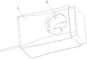
图1是本发明提供的pH胶囊的结构示意图。Fig. 1 is a schematic structural view of the pH capsule provided by the present invention.
图2是本发明提供的pH胶囊的爆炸示意图。Fig. 2 is a schematic exploded view of the pH capsule provided by the present invention.
图3是本发明提供的pH胶囊的剖视图。Fig. 3 is a sectional view of the pH capsule provided by the present invention.
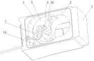
图4是本发明提供的吸附穿刺固定装置的结构示意图。Fig. 4 is a schematic structural view of the adsorption puncture fixation device provided by the present invention.
图5是本发明提供的夹持臂处于初始状态时的结构示意图。Fig. 5 is a schematic structural view of the clamping arm provided by the present invention in its initial state.
图6是本发明提供的夹持臂处于工作状态时的结构示意图。Fig. 6 is a schematic structural view of the clamping arm provided by the present invention in a working state.
图中,1、pH胶囊;2、负压吸入孔;3、容纳腔;4、旋转轴;5、夹持臂;6、旋转穿刺针;7、扭簧;8、连接孔一;9、弯折部一;10、限位部;11、限位凹槽;12、连接孔二;13、弯折部二;14、拉线;15、连接孔三;16、限位体;a、铰接点一;b、铰接点二;L、铰接点一与旋转轴的垂直连线。In the figure, 1. pH capsule; 2. Negative pressure suction hole; 3. Accommodating cavity; 4. Rotation shaft; 5. Clamping arm; 6. Rotating puncture needle; 7. Torsion spring;
具体实施方式Detailed ways
以下是本发明的具体实施例并结合附图,对本发明的技术方案作进一步的描述,但本发明并不限于这些实施例。The following are specific embodiments of the present invention and in conjunction with the accompanying drawings, the technical solutions of the present invention are further described, but the present invention is not limited to these embodiments.
如图1所示的pH胶囊1上,其上设有负压吸入孔2,如图2和图3所示,负压吸入孔2的侧部具有与负压吸入孔2连通的容纳腔3。如图2所示,带自锁功能的吸附穿刺固定装置包括设于容纳腔3内的旋转轴4、套设在旋转轴4上的夹持臂5和用于驱动夹持臂5绕旋转轴4由初始状态旋转至工作状态的驱动件,夹持臂5上具有初始状态位于容纳腔3内的旋转穿刺针6,当夹持臂5处于工作状态时旋转穿刺针6伸入至负压吸入孔2内,pH胶囊1与夹持臂5之间设有自锁组件。On the
当夹持臂5处于初始状态时,在自锁组件的作用下,夹持臂5实现自锁;当夹持臂5处于工作状态,在自锁组件的作用下,夹持臂5也能实现自锁。本实施例中,旋转穿刺针6在穿刺状态下,可横跨整个负压吸入孔2。当黏膜进入到负压吸入孔2内后,旋转穿刺针6可穿透黏膜的两侧,即从黏膜的一侧穿入,从黏膜的另一侧穿出,黏膜不会出现滑移、不易脱落。When the
如图2所示,旋转轴4平行于负压吸入孔2的轴线设置,旋转穿刺针6位于夹持臂5远离旋转轴4的一端处且所述的夹持臂5沿其旋转方向弧形延伸。As shown in Figure 2, the
如图4所示,自锁组件包括一具有弹力的弹性件,容纳腔3的内壁上具有铰接点一a,夹持臂5上具有铰接点二b,弹性件的一端铰接在铰接点一a处,另一端铰接在铰接点二b处,当夹持臂5处于初始状态时铰接点二b位于铰接点一a与旋转轴4垂直连线L的一侧,当夹持臂5处于工作状态时铰接点二b位于铰接点一a与旋转轴4垂直连线L的另一侧。As shown in Figure 4, the self-locking assembly includes an elastic member with elastic force, the inner wall of the
当夹持臂5处于初始状态时,弹性件施加在夹持臂5上的弹力可使夹持臂5保持在初始状态位置。当人体黏膜组织被吸入到负压吸入孔2内后,驱动件开始工作,驱动件作用在夹持臂5上的力大于弹性件作用在夹持臂5上的力,驱动夹持臂5绕旋转轴4旋转,在旋转的过程中,弹性件的弹力逐渐增大,当旋转轴4、铰接点二b和铰接点一a三点共线时,弹性件的弹力达到最大。驱动件继续驱动,铰接点二b越过铰接点一a与旋转轴4的垂直连线L后进入到另一侧,弹性件的弹力施加在夹持臂5上使夹持臂5向工作状态方向旋转,当夹持臂5完全处于工作状态时,弹性件使夹持臂5保持在工作状态位置,在没有外力作用下,旋转臂不会回退。When the
当pH胶囊1从人体黏膜组织上脱落后,用镊子扳动弹性件,使弹性件由铰接点一a与旋转轴4垂直连线L的另一侧复位至铰接点一a与旋转轴4垂直连线L的一侧,便于pH胶囊1的再次使用。When the
本实施例中,弹性件为扭簧7,如图2和图4所示,夹持臂5上具有与旋转轴4平行的连接孔一8,扭簧7的一端具有伸入至连接孔一8内的弯折部一9,弯折部一9上具有限位部10。扭簧7转动时以弯折部一9的中轴线为旋转中心,因此铰接点二b位于弯折部一9的中轴线上。In this embodiment, the elastic member is a
如图2所示,容纳腔3远离负压吸入孔2的一侧上具有限位凹槽11,限位凹槽11上具有与旋转轴4平行的连接孔二12,簧的另一端具有伸入至连接孔二12内的弯折部二13。扭簧7同时以弯折部二13的中轴线为旋转中心,铰接点二b位于弯折部二13的中轴线上。As shown in Figure 2, the
本实施例中,驱动件包括一端固定在夹持臂5上的拉线14, 当夹持臂5处于初始状态时所述的拉线14与夹持臂5的固定点位于铰接点一a与旋转轴4垂直连线L的一侧,容纳腔3远离负压吸入孔2的一侧上具有穿出孔,穿出孔位于铰接点一a与旋转轴4垂直连线L的另一侧,如图5所示,拉线14的另一端由该穿出孔穿出。In this embodiment, the driver includes a
穿出孔的直径较小,以拉线14能穿出为准,当负压吸入孔2负压吸风时,由穿出孔进入的空气可忽略不计,因此设置的穿出孔不会影响负压吸入孔2的负压吸风效果。拉动拉线14时,拉线14作用在夹持臂5上的扭矩大于弹性件作用在夹持臂5上的扭矩,从而驱动夹持臂5绕旋转轴4旋转,当铰接点二b越过铰接点一a与旋转轴4的垂直连线L后进入到另一侧,此时可松开拉线14,由弹性件驱动夹持臂5继续旋转直到夹持臂5旋转到工作状态。The diameter of the piercing hole is relatively small, and it is as the criterion that the
本实施例中,拉线14与弹性件位于夹持臂5的不同侧,防止拉线14与弹性件缠绕在一起。In this embodiment, the
如图4所示,夹持臂5上具有与旋转轴4平行的连接孔三15,如图5所示,夹持臂5靠近弹性件的一端具有外径大于连接孔三15外径的限位体16,拉线14穿过连接孔三15后与限位体16固连。As shown in Figure 4, there is a connecting
如图4所示,当夹持臂5处于初始状态时所述连接孔三15至旋转轴4的距离大于连接孔一8至旋转轴4的距离。根据杠杆原理,当连接孔三15至旋转轴4的距离越大,则在拉线14时就越轻松。As shown in FIG. 4 , when the
在初始状态下,如图5所示,扭簧7在自身弹力作用下对夹持臂5产生一个扭矩,使夹持臂5保持在初始状态,旋转穿刺针6完全位于容纳腔3的内部。负压吸入孔2负压吸风,将人体黏膜组织吸入到负压吸入孔2内,拉动拉线14,拉线14的拉力对夹持臂5产生一个扭矩,此扭矩大于扭簧7作用在夹持臂5上的扭矩,因此夹持臂5开始旋转,当旋转轴4、铰接点二b和铰接点一a三点共线时,扭簧7的弹力达到最大。如图6所示,当铰接点二b越过铰接点一a与旋转轴4的垂直连线L后进入到另一侧,此时可松开拉线14,由扭簧7驱动夹持臂5继续旋转直到夹持臂5旋转到工作状态,此时旋转穿刺针6已经刺入到人体黏膜组织内,扭簧7作用在夹持臂5上的力大于黏膜对夹持臂5的回退反作用力,夹持臂5不能回退,达到将pH胶囊1固定在人体黏膜组织上的目的。In the initial state, as shown in FIG. 5 , the
本文中所描述的具体实施例仅仅是对本发明精神作举例说明。本发明所属技术领域的技术人员可以对所描述的具体实施例做各种各样的修改或补充或采用类似的方式替代,但并不会偏离本发明的精神或者超越所附权利要求书所定义的范围。The specific embodiments described herein are merely illustrative of the spirit of the invention. Those skilled in the art to which the present invention belongs can make various modifications or supplements to the described specific embodiments or adopt similar methods to replace them, but they will not deviate from the spirit of the present invention or go beyond the definition of the appended claims range.
Claims (8)
Priority Applications (2)
| Application Number | Priority Date | Filing Date | Title |
|---|---|---|---|
| CN201711356845.4ACN108095806B (en) | 2017-12-16 | 2017-12-16 | Adsorption puncture fixing device with self-locking function |
| PCT/CN2018/106109WO2019114354A1 (en) | 2017-12-16 | 2018-09-18 | Adsorption puncture fixing device with self-locking function |
Applications Claiming Priority (1)
| Application Number | Priority Date | Filing Date | Title |
|---|---|---|---|
| CN201711356845.4ACN108095806B (en) | 2017-12-16 | 2017-12-16 | Adsorption puncture fixing device with self-locking function |
Publications (2)
| Publication Number | Publication Date |
|---|---|
| CN108095806A CN108095806A (en) | 2018-06-01 |
| CN108095806Btrue CN108095806B (en) | 2023-04-28 |
Family
ID=62216515
Family Applications (1)
| Application Number | Title | Priority Date | Filing Date |
|---|---|---|---|
| CN201711356845.4AActiveCN108095806B (en) | 2017-12-16 | 2017-12-16 | Adsorption puncture fixing device with self-locking function |
Country Status (2)
| Country | Link |
|---|---|
| CN (1) | CN108095806B (en) |
| WO (1) | WO2019114354A1 (en) |
Families Citing this family (6)
| Publication number | Priority date | Publication date | Assignee | Title |
|---|---|---|---|---|
| CN108095806B (en)* | 2017-12-16 | 2023-04-28 | 重庆金山科技(集团)有限公司 | Adsorption puncture fixing device with self-locking function |
| CN109938697B (en)* | 2019-03-29 | 2023-07-25 | 重庆金山医疗技术研究院有限公司 | Elastic clamping structure and clamping device of detection equipment |
| CN109875516B (en)* | 2019-03-29 | 2022-04-01 | 重庆金山医疗技术研究院有限公司 | Off-line type detection equipment clamping device |
| CN110151110B (en)* | 2019-06-05 | 2024-04-23 | 上海长海医院 | Fixable capsule endoscope for monitoring gastrorrhagia and real-time monitoring system for gastrorrhagia |
| CN111839468B (en)* | 2020-08-18 | 2024-09-10 | 重庆金山医疗技术研究院有限公司 | PH capsule operating means and detecting instrument |
| CN119896538A (en)* | 2025-04-02 | 2025-04-29 | 湖南极索医疗科技有限公司 | A control system and method for surgical intervention robot |
Citations (6)
| Publication number | Priority date | Publication date | Assignee | Title |
|---|---|---|---|---|
| CN101808567A (en)* | 2007-09-26 | 2010-08-18 | 奥林巴斯医疗株式会社 | Introduction-into-subject system |
| WO2010137705A1 (en)* | 2009-05-29 | 2010-12-02 | オリンパスメディカルシステムズ株式会社 | Capsule type medical device |
| CN102209487A (en)* | 2008-11-13 | 2011-10-05 | 奥林巴斯医疗株式会社 | Capsule-type medical device |
| CN103054618A (en)* | 2013-01-25 | 2013-04-24 | 北京中法派尔特医疗设备有限公司 | Surgical suturing instrument with trigger locking device |
| TWM506869U (en)* | 2015-04-15 | 2015-08-11 | Tong Lung Metal Ind Co Ltd | Electronic lock positioning mechanism |
| CN106420015A (en)* | 2016-10-26 | 2017-02-22 | 重庆金山医疗器械有限公司 | Esophagus detector, esophagus built-in detecting device and puncture device thereof |
Family Cites Families (9)
| Publication number | Priority date | Publication date | Assignee | Title |
|---|---|---|---|---|
| JPS55136040A (en)* | 1979-04-10 | 1980-10-23 | Olympus Optical Co | Capsule device for medical treatment |
| US6535764B2 (en)* | 2001-05-01 | 2003-03-18 | Intrapace, Inc. | Gastric treatment and diagnosis device and method |
| US7946979B2 (en)* | 2002-12-26 | 2011-05-24 | Given Imaging, Ltd. | Immobilizable in vivo sensing device |
| US20050245788A1 (en)* | 2004-04-28 | 2005-11-03 | Medtronic, Inc. | Esophageal delivery system and method with position indexing |
| DE602009001050D1 (en)* | 2008-06-04 | 2011-05-26 | Olympus Medical Systems Corp | Capsular medical device |
| US8219171B2 (en)* | 2010-03-16 | 2012-07-10 | Given Imaging Ltd. | Delivery device for implantable monitor |
| WO2013003824A1 (en)* | 2011-06-29 | 2013-01-03 | Rani Therapeutics, Llc | Therapeutic agent preparations for delivery into a lumen of the intestinal tract using a swallowable drug delivery device |
| US10046111B2 (en)* | 2013-09-05 | 2018-08-14 | Sanofi-Aventis Deutchland Gmbh | Needle insertion and retraction arrangment with manually triggered, spring-loaded drive mechanism |
| CN108095806B (en)* | 2017-12-16 | 2023-04-28 | 重庆金山科技(集团)有限公司 | Adsorption puncture fixing device with self-locking function |
- 2017
- 2017-12-16CNCN201711356845.4Apatent/CN108095806B/enactiveActive
- 2018
- 2018-09-18WOPCT/CN2018/106109patent/WO2019114354A1/ennot_activeCeased
Patent Citations (6)
| Publication number | Priority date | Publication date | Assignee | Title |
|---|---|---|---|---|
| CN101808567A (en)* | 2007-09-26 | 2010-08-18 | 奥林巴斯医疗株式会社 | Introduction-into-subject system |
| CN102209487A (en)* | 2008-11-13 | 2011-10-05 | 奥林巴斯医疗株式会社 | Capsule-type medical device |
| WO2010137705A1 (en)* | 2009-05-29 | 2010-12-02 | オリンパスメディカルシステムズ株式会社 | Capsule type medical device |
| CN103054618A (en)* | 2013-01-25 | 2013-04-24 | 北京中法派尔特医疗设备有限公司 | Surgical suturing instrument with trigger locking device |
| TWM506869U (en)* | 2015-04-15 | 2015-08-11 | Tong Lung Metal Ind Co Ltd | Electronic lock positioning mechanism |
| CN106420015A (en)* | 2016-10-26 | 2017-02-22 | 重庆金山医疗器械有限公司 | Esophagus detector, esophagus built-in detecting device and puncture device thereof |
Also Published As
| Publication number | Publication date |
|---|---|
| WO2019114354A1 (en) | 2019-06-20 |
| CN108095806A (en) | 2018-06-01 |
Similar Documents
| Publication | Publication Date | Title |
|---|---|---|
| CN108095806B (en) | Adsorption puncture fixing device with self-locking function | |
| JP2005537110A5 (en) | ||
| CN107854265A (en) | A kind of thoracic surgery tapping system | |
| CN210354740U (en) | A kind of ultrasound examination auxiliary device | |
| CN105816238B (en) | A kind of endoscopic inferior mucosa excision lifting cutter | |
| CN203953740U (en) | Digestive System Department dislodger auxiliary device | |
| CN215689871U (en) | Traditional chinese medical science internal medicine acupuncture locator | |
| CN207996226U (en) | A kind of extended type Lithotomy forceps | |
| CN107789148A (en) | A kind of B ultrasound operation table used suitable for weak patient | |
| CN220025850U (en) | Surgical clip for interventional surgery | |
| CN208659486U (en) | Absorption punctures fixed device | |
| CN222955496U (en) | A drainage puncture device for cardiology | |
| CN210727706U (en) | Wired stomach capsule endoscope structure | |
| CN210962376U (en) | Hand-operated rotary tooth taking device | |
| CN109938697B (en) | Elastic clamping structure and clamping device of detection equipment | |
| CN107753228A (en) | A kind of Ultrasound intervention operation table | |
| CN107550549B (en) | A flexible cable-driven active flexible needle | |
| CN202654251U (en) | Tool for tooth orthodontics | |
| CN208785591U (en) | Temporary heart Pacing lead | |
| CN206080473U (en) | Endoscope suction device | |
| CN219480188U (en) | A kind of biopsy forceps with adjustable clamp head angle | |
| CN217854006U (en) | A kind of subcutaneous tunnel passage for ventriculoperitoneal shunt | |
| CN221845767U (en) | A three-lumen two-balloon catheter guide wire that is easy to store | |
| CN209529275U (en) | Adjustable Le cuts power formula cord holder | |
| CN203042372U (en) | Pincers special for laparoscope tumor operation |
Legal Events
| Date | Code | Title | Description |
|---|---|---|---|
| PB01 | Publication | ||
| PB01 | Publication | ||
| SE01 | Entry into force of request for substantive examination | ||
| SE01 | Entry into force of request for substantive examination | ||
| TA01 | Transfer of patent application right | Effective date of registration:20180831 Address after:401120 18 neon Road, two Road Industrial Park, Yubei District, Chongqing Applicant after:CHONGQING JINSHAN SCIENCE & TECHNOLOGY (GROUP) Co.,Ltd. Address before:401120 1 office buildings, Jinshan International Industrial City, 18 of Nei sang Road, Hui Xing street, Yubei District, Chongqing. Applicant before:CHONGQING JINSHAN MEDICAL APPLIANCE Co.,Ltd. | |
| TA01 | Transfer of patent application right | ||
| GR01 | Patent grant | ||
| GR01 | Patent grant | ||
| CP03 | Change of name, title or address | Address after:401120 18 neon Road, two Road Industrial Park, Yubei District, Chongqing Patentee after:Chongqing Jinshan Technology Group Co.,Ltd. Country or region after:China Address before:401120 18 neon Road, two Road Industrial Park, Yubei District, Chongqing Patentee before:CHONGQING JINSHAN SCIENCE & TECHNOLOGY (GROUP) Co.,Ltd. Country or region before:China | |
| CP03 | Change of name, title or address |