CN108058561B - Active suspension system capable of changing rigidity and damping characteristics of suspension system - Google Patents
Active suspension system capable of changing rigidity and damping characteristics of suspension systemDownload PDFInfo
- Publication number
- CN108058561B CN108058561BCN201711377026.8ACN201711377026ACN108058561BCN 108058561 BCN108058561 BCN 108058561BCN 201711377026 ACN201711377026 ACN 201711377026ACN 108058561 BCN108058561 BCN 108058561B
- Authority
- CN
- China
- Prior art keywords
- motor
- suspension system
- suspension
- driving
- vehicle
- Prior art date
- Legal status (The legal status is an assumption and is not a legal conclusion. Google has not performed a legal analysis and makes no representation as to the accuracy of the status listed.)
- Active
Links
- 239000000725suspensionSubstances0.000titleclaimsabstractdescription104
- 238000013016dampingMethods0.000titleclaimsabstractdescription27
- 238000000034methodMethods0.000claimsdescription7
- 238000006243chemical reactionMethods0.000claimsdescription5
- 230000006835compressionEffects0.000claimsdescription3
- 238000007906compressionMethods0.000claimsdescription3
- 230000008859changeEffects0.000abstractdescription8
- 230000007246mechanismEffects0.000abstractdescription4
- 230000009467reductionEffects0.000abstractdescription4
- 238000010586diagramMethods0.000description8
- 238000009434installationMethods0.000description4
- 238000006073displacement reactionMethods0.000description3
- 238000005096rolling processMethods0.000description3
- 230000008569processEffects0.000description2
- 230000000712assemblyEffects0.000description1
- 238000000429assemblyMethods0.000description1
- 230000009286beneficial effectEffects0.000description1
- 230000007935neutral effectEffects0.000description1
- 238000013040rubber vulcanizationMethods0.000description1
- 230000035936sexual powerEffects0.000description1
Images


Classifications
- B—PERFORMING OPERATIONS; TRANSPORTING
- B60—VEHICLES IN GENERAL
- B60G—VEHICLE SUSPENSION ARRANGEMENTS
- B60G17/00—Resilient suspensions having means for adjusting the spring or vibration-damper characteristics, for regulating the distance between a supporting surface and a sprung part of vehicle or for locking suspension during use to meet varying vehicular or surface conditions, e.g. due to speed or load
- B60G17/015—Resilient suspensions having means for adjusting the spring or vibration-damper characteristics, for regulating the distance between a supporting surface and a sprung part of vehicle or for locking suspension during use to meet varying vehicular or surface conditions, e.g. due to speed or load the regulating means comprising electric or electronic elements
- B60G17/0152—Resilient suspensions having means for adjusting the spring or vibration-damper characteristics, for regulating the distance between a supporting surface and a sprung part of vehicle or for locking suspension during use to meet varying vehicular or surface conditions, e.g. due to speed or load the regulating means comprising electric or electronic elements characterised by the action on a particular type of suspension unit
- B60G17/0157—Resilient suspensions having means for adjusting the spring or vibration-damper characteristics, for regulating the distance between a supporting surface and a sprung part of vehicle or for locking suspension during use to meet varying vehicular or surface conditions, e.g. due to speed or load the regulating means comprising electric or electronic elements characterised by the action on a particular type of suspension unit non-fluid unit, e.g. electric motor
- B—PERFORMING OPERATIONS; TRANSPORTING
- B60—VEHICLES IN GENERAL
- B60G—VEHICLE SUSPENSION ARRANGEMENTS
- B60G17/00—Resilient suspensions having means for adjusting the spring or vibration-damper characteristics, for regulating the distance between a supporting surface and a sprung part of vehicle or for locking suspension during use to meet varying vehicular or surface conditions, e.g. due to speed or load
- B60G17/015—Resilient suspensions having means for adjusting the spring or vibration-damper characteristics, for regulating the distance between a supporting surface and a sprung part of vehicle or for locking suspension during use to meet varying vehicular or surface conditions, e.g. due to speed or load the regulating means comprising electric or electronic elements
- B60G17/016—Resilient suspensions having means for adjusting the spring or vibration-damper characteristics, for regulating the distance between a supporting surface and a sprung part of vehicle or for locking suspension during use to meet varying vehicular or surface conditions, e.g. due to speed or load the regulating means comprising electric or electronic elements characterised by their responsiveness, when the vehicle is travelling, to specific motion, a specific condition, or driver input
- B60G17/0162—Resilient suspensions having means for adjusting the spring or vibration-damper characteristics, for regulating the distance between a supporting surface and a sprung part of vehicle or for locking suspension during use to meet varying vehicular or surface conditions, e.g. due to speed or load the regulating means comprising electric or electronic elements characterised by their responsiveness, when the vehicle is travelling, to specific motion, a specific condition, or driver input mainly during a motion involving steering operation, e.g. cornering, overtaking
- B—PERFORMING OPERATIONS; TRANSPORTING
- B60—VEHICLES IN GENERAL
- B60G—VEHICLE SUSPENSION ARRANGEMENTS
- B60G2202/00—Indexing codes relating to the type of spring, damper or actuator
- B60G2202/40—Type of actuator
- B60G2202/42—Electric actuator
- B—PERFORMING OPERATIONS; TRANSPORTING
- B60—VEHICLES IN GENERAL
- B60G—VEHICLE SUSPENSION ARRANGEMENTS
- B60G2800/00—Indexing codes relating to the type of movement or to the condition of the vehicle and to the end result to be achieved by the control action
- B60G2800/24—Steering, cornering
- Y—GENERAL TAGGING OF NEW TECHNOLOGICAL DEVELOPMENTS; GENERAL TAGGING OF CROSS-SECTIONAL TECHNOLOGIES SPANNING OVER SEVERAL SECTIONS OF THE IPC; TECHNICAL SUBJECTS COVERED BY FORMER USPC CROSS-REFERENCE ART COLLECTIONS [XRACs] AND DIGESTS
- Y02—TECHNOLOGIES OR APPLICATIONS FOR MITIGATION OR ADAPTATION AGAINST CLIMATE CHANGE
- Y02T—CLIMATE CHANGE MITIGATION TECHNOLOGIES RELATED TO TRANSPORTATION
- Y02T10/00—Road transport of goods or passengers
- Y02T10/60—Other road transportation technologies with climate change mitigation effect
- Y02T10/72—Electric energy management in electromobility
Landscapes
- Engineering & Computer Science (AREA)
- Mechanical Engineering (AREA)
- Vehicle Body Suspensions (AREA)
Abstract
Translated fromChinese
Description
Translated fromChinese技术领域technical field
本发明涉及一种主动式悬架系统,属于机动车悬架系统技术领域,尤其涉及一种可改变悬挂系统的刚度及阻尼特性的主动式悬架系统。The invention relates to an active suspension system, which belongs to the technical field of motor vehicle suspension systems, in particular to an active suspension system capable of changing the stiffness and damping characteristics of the suspension system.
背景技术Background technique
悬架是现代汽车上的主要总成之一。它把车架(或车身)与车轴(或车轮)弹性的连接起来。其主要功能是传递作用在车轮与车架(或车身)之间的一切力和力矩,并缓和不平路面对车架(或车身)的冲击和振动,以保证车辆的正常行驶。随着汽车电气化、智能化的发展,汽车的乘坐舒适性和操控稳定性越来越受到各汽车厂商的重视,主动控制悬架可根据车辆行驶工况及道路条件,通过改变悬挂系统的刚度及阻尼特性,起到控制车身振动和减缓不平路面对车辆的冲击,增进汽车操纵稳定性、乘坐舒适性等性能。Suspension is one of the major assemblies on a modern car. It elastically connects the frame (or body) to the axle (or wheel). Its main function is to transmit all the forces and moments acting between the wheel and the frame (or body), and ease the impact and vibration of the uneven road on the frame (or body), so as to ensure the normal driving of the vehicle. With the development of automobile electrification and intelligence, automobile manufacturers pay more and more attention to the ride comfort and handling stability. The active control suspension can change the stiffness and The damping characteristics can control the vibration of the vehicle body and reduce the impact of uneven roads on the vehicle, and improve the vehicle's handling stability and ride comfort.
发明内容Contents of the invention
本发明提供了一种可改变悬挂系统的刚度及阻尼特性的主动式悬架系统,其不仅结构简单,而且能够控制车身振动和减缓不平路面对车辆的冲击,增进汽车操纵稳定性、乘坐舒适性等性能。The invention provides an active suspension system capable of changing the stiffness and damping characteristics of the suspension system, which not only has a simple structure, but also can control the vibration of the vehicle body and slow down the impact of uneven roads on the vehicle, thereby improving the steering stability and ride comfort of the vehicle sexual performance.
为解决上述技术问题,本发明采用了这样一种可改变悬挂系统的刚度及阻尼特性的主动式悬架系统,其包括车架和车轴,所述车架和所述车轴之间连接有悬架控制臂,所述悬架控制臂一端与所述车轴铰接,另一端与所述车架铰接,还包括传感器,用于采集道路状况及车辆工况数据信息;电控单元,用于分析传感器采集的数据信息并根据该数据信息控制主动驱动模块的驱动力矩和输出扭矩;主动驱动模块,用于保证悬架系统的刚度和阻尼的最优匹配;所述主动驱动模块包括多个与所述悬架控制臂直接连接或通过减速机构连接的驱动电机;所述驱动电机的电机壳体与所述车架固接,所述驱动电机的电机主轴(可直接或通过减速机构)与所述悬架控制臂固接,或者所述驱动电机的电机壳体与所述悬架控制臂固接,所述驱动电机的电机主轴(可直接或通过减速机构)与所述车架固接;所述驱动电机与所述电控单元电连接,所述电控单元与所述传感器电连接。In order to solve the above technical problems, the present invention adopts such an active suspension system that can change the stiffness and damping characteristics of the suspension system, which includes a vehicle frame and an axle, and a suspension is connected between the vehicle frame and the axle Control arm, one end of the suspension control arm is hinged to the axle, and the other end is hinged to the frame, and also includes a sensor for collecting road conditions and vehicle operating condition data information; an electronic control unit for analyzing the data collected by the sensor and control the driving torque and output torque of the active driving module according to the data information; the active driving module is used to ensure the optimal matching of the stiffness and damping of the suspension system; the active driving module includes multiple The drive motor directly connected to the control arm of the frame or through the reduction mechanism; The frame control arm is affixed, or the motor housing of the drive motor is affixed to the suspension control arm, and the motor spindle of the drive motor (either directly or through a reduction mechanism) is affixed to the vehicle frame; The drive motor is electrically connected to the electric control unit, and the electric control unit is electrically connected to the sensor.
在本发明的一种优选实施方案中,所述驱动电机的电机壳体通过弹性铰接件固接在所述悬架控制臂上;所述电机壳体与所述弹性铰接件的内圈过盈配合连接;所述弹性铰接件的外圈与所述悬架控制臂固接;所述驱动电机的输出端(可直接或通过减速机构)与车架固接。In a preferred embodiment of the present invention, the motor casing of the drive motor is fixed on the suspension control arm through an elastic hinge; the motor casing is connected to the inner ring of the elastic hinge Interference fit connection; the outer ring of the elastic hinge is fixedly connected to the suspension control arm; the output end of the driving motor (either directly or through a reduction mechanism) is fixedly connected to the vehicle frame.
在本发明的一种优选实施方案中,利于主动驱动模块保证悬架系统的刚度和阻尼的方法如下:侧倾、转向工况:通过传感器感知该工况,通过电控单元控制车辆左右两侧的悬架驱动电机旋转驱动方向,使其产生的抗扭力矩以抵抗车身的侧倾力矩,减小侧身侧倾角,实现两侧悬架的对扭以抵抗车辆侧倾;不平路面行驶工况:通过传感器感知该工况,通过电控单元控制增加悬架压缩侧电机的输出力矩,同时控制输出力矩随电机输出轴转动角度的增加而迅速增大,以实现悬架的非线性特性,提供更好的刚度、阻尼特性。In a preferred embodiment of the present invention, the method for the active drive module to ensure the stiffness and damping of the suspension system is as follows: roll and steering operating conditions: sense the operating conditions through sensors, and control the left and right sides of the vehicle through the electronic control unit The suspension drive motor rotates the driving direction, so that the anti-torque torque generated by it can resist the rolling moment of the vehicle body, reduce the sideways roll angle, and realize the anti-twist of the suspension on both sides to resist the vehicle roll; driving conditions on uneven roads : Perceive the working condition through the sensor, increase the output torque of the motor on the compression side of the suspension through the control of the electronic control unit, and at the same time control the output torque to increase rapidly with the increase of the rotation angle of the motor output shaft, so as to realize the nonlinear characteristics of the suspension and provide Better stiffness and damping characteristics.
在本发明的一种优选实施方案中,车辆悬架系统的刚度与主动驱动模块的电机扭矩和电机主轴转角的关系为:In a preferred embodiment of the present invention, the relationship between the stiffness of the vehicle suspension system and the motor torque of the active drive module and the rotation angle of the motor spindle is:

其中:K-悬架系统刚度,a-转换系数,ΔM-电机扭矩,L2-电机的中性轴线到轮胎接触点的水平距离,Δα-电机主轴转角。Among them: K-suspension system stiffness, a-conversion coefficient, ΔM-motor torque, L2 -horizontal distance from the neutral axis of the motor to the tire contact point, Δα-motor spindle rotation angle.
本发明的有益效果是:本发明通过在现有的悬架系统运动件上增加驱动电机,并使其输出端与车架/车身连接,然后根据车辆行驶工况及道路条件及时调整驱动电机的电机扭矩和主轴转角从而实现了根据路况实时改变悬挂系统的刚度及阻尼特性,起到控制车身振动和减缓不平路面对车辆的冲击,增进汽车操纵稳定性、乘坐舒适性等性能。The beneficial effects of the present invention are: the present invention increases the driving motor on the moving parts of the existing suspension system, and connects its output end with the vehicle frame/body, and then adjusts the driving motor in time according to the driving conditions of the vehicle and road conditions. The torque of the motor and the rotation angle of the main shaft realize the real-time change of the stiffness and damping characteristics of the suspension system according to the road conditions, which can control the vibration of the vehicle body and reduce the impact of the uneven road on the vehicle, and improve the vehicle's handling stability and ride comfort.
附图说明Description of drawings
图1为本发明实施例的一种可改变悬挂系统的刚度及阻尼特性的主动式悬架系统的爆炸视图;Fig. 1 is an exploded view of an active suspension system capable of changing the stiffness and damping characteristics of the suspension system according to an embodiment of the present invention;
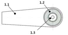
图2为本发明实施例的一种可改变悬挂系统的刚度及阻尼特性的主动式悬架系统的悬架系统运动件示意图;2 is a schematic diagram of moving parts of a suspension system of an active suspension system capable of changing the stiffness and damping characteristics of the suspension system according to an embodiment of the present invention;
图3为本发明实施例的一种可改变悬挂系统的刚度及阻尼特性的主动式悬架系统的悬架系统运动件主视图;3 is a front view of the moving parts of the suspension system of an active suspension system capable of changing the stiffness and damping characteristics of the suspension system according to an embodiment of the present invention;
图4为本发明实施例的一种可改变悬挂系统的刚度及阻尼特性的主动式悬架系统的驱动电机结构示意图;FIG. 4 is a structural schematic diagram of a driving motor of an active suspension system capable of changing the stiffness and damping characteristics of the suspension system according to an embodiment of the present invention;
图5为本发明实施例的一种可改变悬挂系统的刚度及阻尼特性的主动式悬架系统的侧倾工况工作原理示意图;FIG. 5 is a schematic diagram of the working principle of an active suspension system under roll conditions that can change the stiffness and damping characteristics of the suspension system according to an embodiment of the present invention;
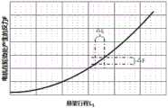
图6为本发明实施例的一种可改变悬挂系统的刚度及阻尼特性的主动式悬架系统的电机在轮边产生的反力与悬架行程的关系示意图;6 is a schematic diagram of the relationship between the reaction force generated by the motor on the wheel and the suspension stroke of an active suspension system that can change the stiffness and damping characteristics of the suspension system according to an embodiment of the present invention;
图7为本发明实施例的一种可改变悬挂系统的刚度及阻尼特性的主动式悬架系统的不平路面行驶工况工作原理示意图;Fig. 7 is a schematic diagram of the working principle of an active suspension system that can change the stiffness and damping characteristics of the suspension system according to an embodiment of the present invention in driving conditions on uneven roads;
图8为本发明实施例的一种可改变悬挂系统的刚度及阻尼特性的主动式悬架系统的安装结构示意图。FIG. 8 is a schematic diagram of an installation structure of an active suspension system capable of changing the stiffness and damping characteristics of the suspension system according to an embodiment of the present invention.
具体实施方式Detailed ways
为了使本发明的目的、技术方案及优点更加清楚明白,以下结合附图及实施例,对本发明进行进一步详细说明。应当理解,此处所描述的具体实施例仅用以解释本发明,并不用于限定本发明。In order to make the object, technical solution and advantages of the present invention more clear, the present invention will be further described in detail below in conjunction with the accompanying drawings and embodiments. It should be understood that the specific embodiments described here are only used to explain the present invention, not to limit the present invention.
由说明书附图所示的一种可改变悬挂系统的刚度及阻尼特性的主动式悬架系统的结构示意图可知,本发明一种可改变悬挂系统的刚度及阻尼特性的主动式悬架系统,其包括与悬架系统运动件1.1连接的主动驱动模块1、与主动驱动模块1连接的可进行判定及根据道路情况和使用工况进行避震驱动功能设定的电控单元3、与电控单元2连接的路况传感器。It can be seen from the structural diagram of an active suspension system capable of changing the stiffness and damping characteristics of the suspension system shown in the accompanying drawings, the present invention is an active suspension system capable of changing the stiffness and damping characteristics of the suspension system. It includes an
如图2所示,上述方案中,主动驱动模块1包括与悬架系统运动件1.1连接的驱动电机1.3和与驱动电机1.3外壳连接的弹性铰接件1.2,其中驱动电机1.3通过弹性铰接件1.2与悬架系统运动件1.1相连。弹性铰接件1.2与悬架系统运动件1.1可以通过过盈配合连接,也可以通过橡胶硫化直接连接等方式连接,只要两者实现连接且不会发生相对运动即可。As shown in Figure 2, in the above scheme, the
当车辆运行时为了提高驾乘的舒适性能和操控性能时,道路路况识别传感器2进行路况道路条件及车辆使用工况数据信息收集处理,并将实时路况数据信息其反馈至电控单元3,电控单元3通过对实时路况数据信息的分析,通过对车辆行驶路面情况的判断及车辆使用工况的判断,发送相应的控制信号至主动驱动模块1,主动驱动模块1通过驱动电机1.3主动调节驱动力矩的大小及扭矩输出特性,电机驱动扭矩通过弹性铰接件1.2将力矩传递给悬架系统运动件1.1,从而实现悬架系统刚度和阻尼的最优匹配,提升悬架系统的操控性能和舒适性能。When the vehicle is running, in order to improve the driving comfort and handling performance, the road
当车辆处于侧倾工况(转向):通过传感器感知该工况,通过控制器控制车辆左右两侧的悬架驱动电机驱动方向,实现两侧悬架的对扭以抵抗车辆侧倾,即通过两侧电机产生的抗扭力矩以抵抗车身的侧倾力矩,减小侧身侧倾角,以提高车辆稳定性和驾乘舒适性。When the vehicle is in the rolling condition (steering): sense the working condition through the sensor, and control the driving direction of the suspension drive motors on the left and right sides of the vehicle through the controller, so as to realize the anti-twist of the suspension on both sides to resist the vehicle roll, that is, through The anti-torque torque generated by the motors on both sides can resist the rolling moment of the vehicle body, reduce the sideways roll angle, and improve vehicle stability and driving comfort.
当车辆处于不平路面行驶工况:当车辆在不平路面行驶时,通过增加悬架压缩侧电机的输出力矩,同时控制输出力矩随电机输出轴转动角度的增加而迅速增大,以实现悬架的非线性特性,提供更好的刚度、阻尼特性。When the vehicle is running on an uneven road: when the vehicle is driving on an uneven road, increase the output torque of the motor on the compression side of the suspension, and at the same time control the output torque to increase rapidly with the increase of the rotation angle of the motor output shaft, so as to realize the suspension. Non-linear characteristics, providing better stiffness and damping characteristics.
而车辆的悬架系统的刚度与驱动电机1.3的电机扭矩和电机主轴转角关系为:The relationship between the stiffness of the suspension system of the vehicle and the motor torque of the drive motor 1.3 and the rotation angle of the motor spindle is:

其中:K-悬架系统刚度,a-转换系数,ΔM-电机扭矩,L2-电机的轴线到轮胎接触点的水平距离,Δα-电机主轴转角。Among them: K-suspension system stiffness, a-conversion coefficient, ΔM-motor torque, L2 -horizontal distance from the motor axis to the tire contact point, Δα-motor spindle rotation angle.
由于悬架系统的位移及轮边力分别于电机主轴的转角以及对应的电机输出扭矩相关,因此通过合理设定电机的相关控制参数(通过系统标定完成),即可动态实现所需要的悬架刚度,满足不同工况的需求。(A-轮胎,B-轮胎接地点,C-地面)Since the displacement and wheel edge force of the suspension system are respectively related to the rotation angle of the motor spindle and the corresponding motor output torque, the required suspension can be dynamically realized by setting the relevant control parameters of the motor reasonably (completed by system calibration). Rigidity, to meet the needs of different working conditions. (A-tire, B-tire contact point, C-ground)
上述公式的推到过程如下:(如附图7)The pushing process of above-mentioned formula is as follows: (as accompanying drawing 7)
对于悬架系统:For the suspension system:
Δα=a×ΔL1Δα=a×ΔL1
Δα-电机主轴转角(以车辆标准载荷状态下的悬架初始位置对应的电机转角设为“0”);Δα-motor spindle rotation angle (the motor rotation angle corresponding to the initial suspension position under the vehicle standard load state is set to "0");
a-转换系数(与悬架结构形式相关,不同的悬架结构形式该系数值不同);a-conversion coefficient (related to the suspension structure, the coefficient value is different for different suspension structures);
L1-悬架行程,即轮胎接地点的垂直位移。L1 - Suspension travel, the vertical displacement of the tire contact point.
由电机扭矩产生的在轮胎接地点处的反向力F为:The reverse force F at the tire contact point produced by the motor torque is:
ΔF=ΔM/L2ΔF=ΔM/L2
悬架系统的刚度:The stiffness of the suspension system:
设当悬架在某一位置附近运动微小位移ΔL1时,电机扭矩变化产生的轮边力变化为ΔF,此时的悬架系统刚度即为:Assuming that when the suspension moves a small displacement ΔL1 near a certain position, the wheel edge force produced by the change of the motor torque changes as ΔF, and the stiffness of the suspension system at this time is:
K=ΔF/ΔL1K=ΔF/ΔL1
其中:K-悬架系统刚度(单位:N/mm)Where: K-suspension system stiffness (unit: N/mm)
图8为一多连杆悬架系统结构示意图,其中,悬架控制臂与车辆主体间的铰接点5均作为驱动电机1.3的安装布置点。以位于中间的铰接点5为例,其中驱动电机1.3、电机壳体6.1、电机主轴6.2、安装轴线6.3具体布置方式是:将电机轴线6.3与铰接点5的轴线重合,以电机主轴6.2作为铰接点的主轴,与铰接点5对应的控制臂安装成一体,以电机壳体兼做固定支架,与车辆主体部分固定。Fig. 8 is a schematic structural diagram of a multi-link suspension system, in which the
该布置安装方式不限于上述形式,如布置空间允许,也可将电机壳体与铰接点5对应的控制臂固定连接,而将主轴与车辆主体进行连接。核心方式就是将电机转子部分与定子部分分别与悬架运动控制件(如多连杆悬架的多个连杆、双横臂独立悬架的上下控制臂、麦弗逊悬架的下摆臂等)和车辆主体部分进行连接,以实现相对运动的控制功能。The arrangement and installation method is not limited to the above-mentioned form, if the arrangement space permits, the motor housing can also be fixedly connected to the control arm corresponding to the
应当理解的是,以上仅为本发明的具体实施方式,但本发明的保护范围并不局限于此,任何熟悉本领域的技术人员在本发明所揭露的技术范围内,可轻易想到的变化或替换,都应涵盖在本发明的保护范围之内。It should be understood that the above are only specific implementations of the present invention, but the scope of protection of the present invention is not limited thereto. Any skilled person in the art can easily think of changes or Replacement should be covered within the protection scope of the present invention.
Claims (1)

Priority Applications (1)
| Application Number | Priority Date | Filing Date | Title |
|---|---|---|---|
| CN201711377026.8ACN108058561B (en) | 2017-12-19 | 2017-12-19 | Active suspension system capable of changing rigidity and damping characteristics of suspension system |
Applications Claiming Priority (1)
| Application Number | Priority Date | Filing Date | Title |
|---|---|---|---|
| CN201711377026.8ACN108058561B (en) | 2017-12-19 | 2017-12-19 | Active suspension system capable of changing rigidity and damping characteristics of suspension system |
Publications (2)
| Publication Number | Publication Date |
|---|---|
| CN108058561A CN108058561A (en) | 2018-05-22 |
| CN108058561Btrue CN108058561B (en) | 2023-07-04 |
Family
ID=62139629
Family Applications (1)
| Application Number | Title | Priority Date | Filing Date |
|---|---|---|---|
| CN201711377026.8AActiveCN108058561B (en) | 2017-12-19 | 2017-12-19 | Active suspension system capable of changing rigidity and damping characteristics of suspension system |
Country Status (1)
| Country | Link |
|---|---|
| CN (1) | CN108058561B (en) |
Families Citing this family (5)
| Publication number | Priority date | Publication date | Assignee | Title |
|---|---|---|---|---|
| CN109664707A (en)* | 2018-11-26 | 2019-04-23 | 武汉新能源汽车工业技术研究院有限公司 | A kind of control method and device of Active suspension |
| CN112339518B (en)* | 2019-08-07 | 2025-03-04 | 广州汽车集团股份有限公司 | Suspension actuating mechanism and active suspension device |
| CN113635726B (en)* | 2021-08-31 | 2023-05-09 | 东风汽车有限公司东风日产乘用车公司 | Integrated control method and system for whole vehicle semi-active suspension system |
| CN115519955B (en)* | 2022-09-16 | 2025-04-22 | 小米汽车科技有限公司 | Suspension system and control method thereof, and vehicle |
| CN222346677U (en)* | 2023-05-19 | 2025-01-14 | 比亚迪股份有限公司 | Suspension system and vehicle |
Citations (5)
| Publication number | Priority date | Publication date | Assignee | Title |
|---|---|---|---|---|
| CN101279578A (en)* | 2007-04-03 | 2008-10-08 | 株式会社电装 | Vehicle control system |
| CN101287617A (en)* | 2005-06-16 | 2008-10-15 | 丰田自动车株式会社 | vehicle stabilizer system |
| CN102729760A (en)* | 2012-07-17 | 2012-10-17 | 山东理工大学 | Real-time optimal damping control algorithm of automobile semi-active suspension system |
| WO2014039981A1 (en)* | 2012-09-07 | 2014-03-13 | University Of Florida Research Foundation, Inc. | Variable stiffness mechanism and system |
| CN106585709A (en)* | 2016-12-21 | 2017-04-26 | 南京航空航天大学 | Automotive chassis integrated system and optimizing method thereof |
Family Cites Families (4)
| Publication number | Priority date | Publication date | Assignee | Title |
|---|---|---|---|---|
| JP2006151262A (en)* | 2004-11-30 | 2006-06-15 | Toyota Motor Corp | Vehicle suspension system |
| JP4438763B2 (en)* | 2006-03-20 | 2010-03-24 | トヨタ自動車株式会社 | Vehicle stabilizer system |
| US8727047B2 (en)* | 2012-01-26 | 2014-05-20 | Claas Industrietechnik Gmbh | Configuration of a two-track tractor |
| US9150070B2 (en)* | 2013-10-18 | 2015-10-06 | GM Global Technology Operations LLC | Actively controlled torsion bar suspension |
- 2017
- 2017-12-19CNCN201711377026.8Apatent/CN108058561B/enactiveActive
Patent Citations (5)
| Publication number | Priority date | Publication date | Assignee | Title |
|---|---|---|---|---|
| CN101287617A (en)* | 2005-06-16 | 2008-10-15 | 丰田自动车株式会社 | vehicle stabilizer system |
| CN101279578A (en)* | 2007-04-03 | 2008-10-08 | 株式会社电装 | Vehicle control system |
| CN102729760A (en)* | 2012-07-17 | 2012-10-17 | 山东理工大学 | Real-time optimal damping control algorithm of automobile semi-active suspension system |
| WO2014039981A1 (en)* | 2012-09-07 | 2014-03-13 | University Of Florida Research Foundation, Inc. | Variable stiffness mechanism and system |
| CN106585709A (en)* | 2016-12-21 | 2017-04-26 | 南京航空航天大学 | Automotive chassis integrated system and optimizing method thereof |
Also Published As
| Publication number | Publication date |
|---|---|
| CN108058561A (en) | 2018-05-22 |
Similar Documents
| Publication | Publication Date | Title |
|---|---|---|
| CN108058561B (en) | Active suspension system capable of changing rigidity and damping characteristics of suspension system | |
| CN113183706B (en) | Double-trailing-arm type active suspension system for full-vector wire control automobile | |
| CN210149098U (en) | A rear suspension system for an electric vehicle | |
| CN109733152B (en) | Disconnectable semi-active transverse stabilizer bar system of automobile and control method | |
| CN108058562B (en) | An active suspension device and its control method | |
| CN202242852U (en) | Electric four-wheel walking device for robot | |
| CN205396209U (en) | Distributing type drive electric motor car chassis configuration | |
| CN206870775U (en) | Mobile platform | |
| CN109515087B (en) | All-terrain mobile robot with active independent suspension system | |
| CN110103653B (en) | An active adjustment device for double wishbone suspension | |
| CN102785565B (en) | Macpherson suspension wheel rim electric driving system for steering wheel | |
| CN217495766U (en) | Rear active suspension system and vehicle | |
| CN110949498B (en) | An electric vehicle and a wheel hub structure with integrated steering and suspension | |
| WO2016200029A1 (en) | Active suspension system allowing load-bearing axis of spring to be controlled | |
| CN109455053B (en) | Automobile self-adaptive rear suspension control system and control method | |
| CN113263909A (en) | Four-wheel independent damping, steering and driving wheeled robot chassis | |
| CN115214286A (en) | Stabilizer bar assembly, suspension system, vehicle and suspension stiffness control method | |
| CN218198486U (en) | Steering mechanism of independent driving wheel | |
| CN115534603A (en) | An all-terrain mobile robot with double-wishbone shock-absorbing suspension | |
| JP2848191B2 (en) | Actuator structure of vehicle suspension device | |
| CN116572683B (en) | Independent suspension wheel rim assembly | |
| CN211106828U (en) | Suspension actuating mechanism and active suspension device | |
| CN104044423B (en) | A kind of series parallel type Independent Suspension mechanism | |
| CN212921854U (en) | Rear rocker arm assembly of electric vehicle | |
| CN115214282B (en) | Torsion bar spring active suspension system and vehicle thereof |
Legal Events
| Date | Code | Title | Description |
|---|---|---|---|
| PB01 | Publication | ||
| PB01 | Publication | ||
| SE01 | Entry into force of request for substantive examination | ||
| SE01 | Entry into force of request for substantive examination | ||
| GR01 | Patent grant | ||
| GR01 | Patent grant |