CN107991775B - Head-mounted visual device capable of human eye tracking and human eye tracking method - Google Patents
Head-mounted visual device capable of human eye tracking and human eye tracking methodDownload PDFInfo
- Publication number
- CN107991775B CN107991775BCN201610947348.0ACN201610947348ACN107991775BCN 107991775 BCN107991775 BCN 107991775BCN 201610947348 ACN201610947348 ACN 201610947348ACN 107991775 BCN107991775 BCN 107991775B
- Authority
- CN
- China
- Prior art keywords
- eye
- image information
- head
- human eye
- eyeball
- Prior art date
- Legal status (The legal status is an assumption and is not a legal conclusion. Google has not performed a legal analysis and makes no representation as to the accuracy of the status listed.)
- Active
Links
Images


Classifications
- G—PHYSICS
- G02—OPTICS
- G02B—OPTICAL ELEMENTS, SYSTEMS OR APPARATUS
- G02B27/00—Optical systems or apparatus not provided for by any of the groups G02B1/00 - G02B26/00, G02B30/00
- G02B27/01—Head-up displays
- G02B27/017—Head mounted
- G02B27/0172—Head mounted characterised by optical features
- G—PHYSICS
- G06—COMPUTING OR CALCULATING; COUNTING
- G06F—ELECTRIC DIGITAL DATA PROCESSING
- G06F3/00—Input arrangements for transferring data to be processed into a form capable of being handled by the computer; Output arrangements for transferring data from processing unit to output unit, e.g. interface arrangements
- G06F3/01—Input arrangements or combined input and output arrangements for interaction between user and computer
- G06F3/011—Arrangements for interaction with the human body, e.g. for user immersion in virtual reality
- G06F3/013—Eye tracking input arrangements
- G—PHYSICS
- G02—OPTICS
- G02B—OPTICAL ELEMENTS, SYSTEMS OR APPARATUS
- G02B27/00—Optical systems or apparatus not provided for by any of the groups G02B1/00 - G02B26/00, G02B30/00
- G02B27/01—Head-up displays
- G02B27/0101—Head-up displays characterised by optical features
- G02B2027/0138—Head-up displays characterised by optical features comprising image capture systems, e.g. camera
Landscapes
- Engineering & Computer Science (AREA)
- Physics & Mathematics (AREA)
- General Engineering & Computer Science (AREA)
- General Physics & Mathematics (AREA)
- Theoretical Computer Science (AREA)
- Human Computer Interaction (AREA)
- Optics & Photonics (AREA)
- Position Input By Displaying (AREA)
- Processing Or Creating Images (AREA)
Abstract
Description
Translated fromChinese技术领域technical field
本发明涉及计算机技术领域,尤其涉及一种头戴式可视设备,具体来说就是一种能够进行人眼追踪的头戴式可视设备及人眼追踪方法。The present invention relates to the field of computer technology, in particular to a head-mounted visual device, in particular to a head-mounted visual device capable of tracking human eyes and a method for tracking human eyes.
背景技术Background technique
近年来,头戴式可视设备的大量涌现,例如,联想眼镜、谷歌眼镜、虚拟现实(VR)游戏眼镜等,虚拟现实(Virtual Reality,VR)、增强现实(Augmented Reality,AR)及混合现实(Mixed Reality,MR)技术逐渐进入我们的日常生活中。头戴式显示器(HMD,也称为头戴式可视设备)是把二维图像直接反射到观看者的眼睛里,具体就是通过一组光学系统(主要是精密光学透镜)放大超微显示屏上的图像,将影像投射于视网膜上,进而将大屏幕图像呈现在观看者眼中,形象点说就是拿放大镜看物体呈现出放大的虚拟物体图像。图像可以直接通过发光二极管(LED)、主动式矩阵液晶显示器(AMLCD)、有机发光二极管(OLED)或液晶附硅(LCOS)获得,也可以通过光纤等传导方式间接获得。显示系统通过准直透镜成像在无穷远处,然后通过反射面把图像反射进人的眼睛里。头戴式可视设备由于其具有便携性、娱乐性等特点,正在悄然改变人们的现代生活。In recent years, a large number of head-mounted visual devices have emerged, such as Lenovo glasses, Google glasses, virtual reality (VR) gaming glasses, etc., virtual reality (VR), augmented reality (AR) and mixed reality (Mixed Reality, MR) technology is gradually entering our daily life. Head-mounted display (HMD, also known as head-mounted visual device) is to directly reflect the two-dimensional image into the viewer's eyes, specifically through a set of optical systems (mainly precision optical lenses) to amplify the ultra-fine display screen The image on the screen is projected on the retina, and then the large-screen image is presented to the viewer's eyes. In terms of image, it is to look at the object with a magnifying glass and present an enlarged virtual object image. Images can be obtained directly through Light Emitting Diodes (LEDs), Active Matrix Liquid Crystal Displays (AMLCDs), Organic Light Emitting Diodes (OLEDs) or Liquid Crystals on Silicon (LCOS), or indirectly through conduction methods such as optical fibers. The display system is imaged at infinity through a collimating lens, and then the image is reflected into the human eye through a reflective surface. Head-mounted visual devices are quietly changing people's modern life due to their portability and entertainment characteristics.
然而,现有头戴式可视设备无法与用户进行主动交互,即佩戴用户主动去操作头戴式可视设备,而头戴式可视设备无法主动去感知用户的关注点及用户的心情,因此,人们想到利用眼动追踪技术去主动感知用户的关注点及用户的心情。但是,如何在头戴式可视设备中使用眼动追踪技术实现对人眼信息实时跟踪获取人眼在空间中的凝视点这一方面,目前还没有很好的解决方案;在头戴式可视设备的设计方面,头戴式可视设备的重量被看作是不可忽略的因素,虽然现有眼动追踪仪已经有比较成熟的产品,但在头戴式可视设备中直接嵌入眼动追踪仪无疑会增加虚拟现实头盔的重量,降低客户体验。However, the existing head-mounted visual device cannot actively interact with the user, that is, the wearing user actively operates the head-mounted visual device, but the head-mounted visual device cannot actively perceive the user's focus and the user's mood. Therefore, people think of using eye-tracking technology to actively perceive the user's focus and the user's mood. However, there is currently no good solution for how to use eye tracking technology in head-mounted visual devices to track human eye information in real time to obtain the gaze point of human eyes in space; In the design of visual equipment, the weight of head-mounted visual equipment is regarded as a factor that cannot be ignored. Although there are relatively mature products of existing eye trackers, eye tracking is directly embedded in head-mounted visual equipment. Trackers will undoubtedly add weight to VR headsets and degrade the customer experience.
因此,如何在不增加头戴式可视设备重量的基础上,让头戴式可视设备具有眼动追踪功能是本领域技术人员长期亟需解决的问题。Therefore, how to make the head-mounted visual device have the eye tracking function without increasing the weight of the head-mounted visual device is a long-term problem that those skilled in the art need to solve urgently.
发明内容SUMMARY OF THE INVENTION
有鉴于此,本发明要解决的技术问题在于提供一种能够进行人眼追踪的头戴式可视设备及人眼追踪方法,解决了现有头戴式可视设备无法追踪人眼观看方位的问题。In view of this, the technical problem to be solved by the present invention is to provide a head-mounted visual device capable of human eye tracking and a human eye tracking method, which solves the problem that the existing head-mounted visual device cannot track the viewing orientation of the human eye. question.
为了解决上述技术问题,本发明的具体实施方式提供一种能够进行人眼追踪的头戴式可视设备,包括:虚拟现实头盔,用于容纳头戴式可视设备;光源,设置于所述虚拟现实头盔内,用于照射人眼眼球;微型摄像机,设置于所述虚拟现实头盔上,用于采集人眼的眼球图像信息,以便服务器根据所述眼球图像信息确定人眼瞳孔的方位信息。In order to solve the above technical problems, specific embodiments of the present invention provide a head-mounted visual device capable of tracking human eyes, including: a virtual reality helmet for accommodating the head-mounted visual device; a light source, arranged on the The virtual reality helmet is used for illuminating the eyeball of the human eye; the miniature camera is arranged on the virtual reality helmet and used to collect the eyeball image information of the human eye, so that the server can determine the orientation information of the human eye pupil according to the eyeball image information.
本发明的具体实施方式还提供一种用于头戴式可视设备的人眼追踪方法,包括:利用LED光源照射人眼眼球;利用微型摄像机采集人眼的眼球图像信息;利用空间映射关系根据所述眼球图像信息确定人眼瞳孔的方位信息。A specific embodiment of the present invention also provides a human eye tracking method for a head-mounted visual device, including: using an LED light source to illuminate the human eyeball; using a miniature camera to collect eyeball image information of the human eye; The eyeball image information determines the orientation information of the pupil of the human eye.
根据本发明的上述具体实施方式可知,能够进行人眼追踪的头戴式可视设备及人眼追踪方法至少具有以下有益效果:通过在头戴式可视设备中嵌入微型摄像机及LED光源,并在虚拟场景中设置多个参考点,利用三维矩阵构建微型摄像机、参考点以及人眼眼球之间的空间映射关系;再利用微型摄像机拍摄眼球图像信息,根据空间映射关系对获取的眼球图像信息进行分析,可实时获取瞳孔聚焦区域,从而确定用户的观看方位,不增加头戴式可视设备的重量,而且不会泄露用户周围的环境信息,提高用户体验度。According to the above-mentioned specific embodiments of the present invention, it can be known that the head-mounted visual device and the human eye tracking method capable of tracking human eyes have at least the following beneficial effects: by embedding a miniature camera and an LED light source in the head-mounted visual device, and Multiple reference points are set in the virtual scene, and the three-dimensional matrix is used to construct the spatial mapping relationship between the micro-camera, the reference points and the human eyeballs; the micro-camera is then used to capture the eyeball image information, and the obtained eyeball image information is processed according to the spatial mapping relationship. Analysis, the pupil focus area can be obtained in real time, so as to determine the user's viewing direction, without increasing the weight of the head-mounted visual device, and without revealing the environmental information around the user, improving the user experience.
应了解的是,上述一般描述及以下具体实施方式仅为示例性及阐释性的,其并不能限制本发明所欲主张的范围。It is to be understood that the foregoing general description and the following detailed description are exemplary and explanatory only and are not intended to limit the scope of the invention as claimed.
附图说明Description of drawings
下面的所附附图是本发明的说明书的一部分,其绘示了本发明的示例实施例,所附附图与说明书的描述一起用来说明本发明的原理。The following accompanying drawings, which are part of the specification of the invention, illustrate exemplary embodiments of the invention, and together with the description of the specification, serve to explain the principles of the invention.
图1A为本发明具体实施方式提供的一种能够进行人眼追踪的头戴式可视设备的主体结构示意图;1A is a schematic diagram of the main structure of a head-mounted visual device capable of human eye tracking provided by a specific embodiment of the present invention;
图1B为本发明具体实施方式提供的一种能够进行人眼追踪的头戴式可视设备的后视结构示意图;1B is a schematic diagram of a rear view of a head-mounted visual device capable of human eye tracking provided by a specific embodiment of the present invention;
图2为本发明具体实施方式提供的一种用于头戴式可视设备的人眼追踪方法的实施例一的流程图;FIG. 2 is a flowchart of Embodiment 1 of a method for eye tracking for a head-mounted visual device provided by specific embodiments of the present invention;
图3为本发明具体实施方式提供的一种用于头戴式可视设备的人眼追踪方法的实施例二的流程图;FIG. 3 is a flowchart of Embodiment 2 of a method for eye tracking for a head-mounted visual device provided by a specific embodiment of the present invention;
图4为本发明具体实施方式提供的微型摄像机、参考点以及人眼眼球之间的空间位置关系三维坐标示意图;4 is a schematic diagram of three-dimensional coordinates of the spatial positional relationship between a miniature camera, a reference point, and a human eye according to a specific embodiment of the present invention;
图5为本发明具体实施方式提供的坐标转换关系图。FIG. 5 is a coordinate conversion relationship diagram provided by a specific embodiment of the present invention.
具体实施方式Detailed ways
为使本发明实施例的目的、技术方案和优点更加清楚明白,下面将以附图及详细叙述清楚说明本发明所揭示内容的精神,任何所属技术领域技术人员在了解本发明内容的实施例后,当可由本发明内容所教示的技术,加以改变及修饰,其并不脱离本发明内容的精神与范围。In order to make the purposes, technical solutions and advantages of the embodiments of the present invention clearer, the following will clearly illustrate the spirit of the disclosed contents of the present invention with the accompanying drawings and detailed description. , when changes and modifications can be made by the technology taught by the content of the present invention, it does not depart from the spirit and scope of the content of the present invention.
本发明的示意性实施例及其说明用于解释本发明,但并不作为对本发明的限定。另外,在附图及实施方式中所使用相同或类似标号的元件/构件是用来代表相同或类似部分。The exemplary embodiments of the present invention and their descriptions are used to explain the present invention, but are not intended to limit the present invention. In addition, elements/members with the same or similar reference numerals used in the drawings and the embodiments are intended to represent the same or similar parts.
关于本文中所使用的“第一”、“第二”、…等,并非特别指称次序或顺位的意思,也非用以限定本发明,其仅为了区别以相同技术用语描述的元件或操作。Regarding the "first", "second", ... etc. used in this document, it does not specifically refer to the order or order, nor is it used to limit the present invention, it is only used to distinguish elements or operations described in the same technical terms. .
关于本文中所使用的方位用语,例如:上、下、左、右、前或后等,仅是参考附图的方位。因此,使用的方位用语是用来说明并非用来限制本创作。Orientation terms used herein, such as: up, down, left, right, front, or rear, etc., refer only to the orientation of the drawings. Accordingly, the terminology of orientation used is illustrative and not intended to limit the creation.
关于本文中所使用的“包含”、“包括”、“具有”、“含有”等等,均为开放性的用语,即意指包含但不限于。As used herein, "comprising," "including," "having," "containing," and the like, are open-ended terms, meaning including but not limited to.
关于本文中所使用的“及/或”,包括所述事物的任一或全部组合。As used herein, "and/or" includes any and all combinations of the stated things.
图1A为本发明具体实施方式提供的一种能够进行人眼追踪的头戴式可视设备的主体结构示意图;图1B为本发明具体实施方式提供的一种能够进行人眼追踪的头戴式可视设备的后视结构示意图;如图1A、图1B所示,在虚拟现实头盔镜片两侧分别设置光源和微型摄像机,一个光源和一个微型摄像机对应于用户的一只眼睛,另外一个光源和另外一个微型摄像机对应于用户的另一只眼睛,光源用于照射人眼眼球,微型摄像机用于采集人眼的眼球图像信息,以便服务器根据所述眼球图像信息确定人眼瞳孔的方位信息。1A is a schematic diagram of the main structure of a head-mounted visual device capable of human eye tracking provided by a specific embodiment of the present invention; FIG. 1B is a head-mounted visual device capable of human eye tracking provided by a specific embodiment of the present invention. A schematic diagram of the rear view structure of the visual device; as shown in Figure 1A and Figure 1B, a light source and a miniature camera are respectively set on both sides of the virtual reality helmet lens, one light source and one miniature camera correspond to one eye of the user, and the other light source and The other micro camera corresponds to the other eye of the user, the light source is used to illuminate the eyeball of the human eye, and the micro camera is used to collect the eyeball image information of the human eye, so that the server can determine the orientation information of the human eye pupil according to the eyeball image information.
该附图所示的具体实施方式中,该头戴式可视设备包括虚拟现实头盔10、光源20和微型摄像机30,其中,虚拟现实头盔10用于容纳头戴式可视设备;光源20设置于所述虚拟现实头盔10内,光源20用于照射人眼眼球;微型摄像机30设置于所述虚拟现实头盔10内,微型摄像机30用于采集人眼的眼球图像信息,以便服务器根据所述眼球图像信息确定人眼瞳孔的方位信息,其中,微型摄像机30可以为微型摄像机、微型照相机等,光源20可以为微型LED光源,微型摄像机30采集人眼的眼球图像信息时,光源20瞬间开启并关闭;微型摄像机30通过微型摄像机的HDMI数据线与服务器连接。人眼瞳孔的方位信息具体指:以人眼水平观看正前方的直线为参考线,然后将观看目标点与人眼瞳孔进行连线,该连线与参考线之间的角度、位置关系信息就是人眼瞳孔的方位信息。In the specific embodiment shown in the figure, the head-mounted visual device includes a
进一步地,所述服务器具体根据微型摄像机30、参考点以及人眼眼球之间的空间位置关系计算出人眼瞳孔的方位信息。参考点的个数至少为4个。Further, the server specifically calculates the orientation information of the pupil of the human eye according to the
另外,如图1B所示,所述光源20具体包括第一LED光源201和第二LED光源202。第一LED光源201设置于所述虚拟现实头盔10的左侧镜片边缘处;第二LED光源202设置于所述虚拟现实头盔10的右侧镜片边缘处;第一LED光源201用于照射左眼眼球;第二LED光源202用于照射右眼眼球。In addition, as shown in FIG. 1B , the
所述微型摄像机30具体包括第一微型摄像机301和第二微型摄像机302。第一微型摄像机301设置于所述虚拟现实头盔10的左侧镜片边缘处;第二微型摄像机302设置于所述虚拟现实头盔10的右侧镜片边缘处;第一微型摄像机301用于拍摄左眼的眼球图像信息;第二微型摄像机302用于拍摄右眼的眼球图像信息。The
本发明的具体实施例中,所述服务器具体根据左眼的眼球图像信息获得左眼注视方位的左眼光轴矢量,并根据右眼的眼球图像信息获得右眼注视方位的右眼光轴矢量,再根据左眼光轴矢量和右眼光轴矢量的相交处确定人眼瞳孔的方位信息。In a specific embodiment of the present invention, the server specifically obtains the left eye optical axis vector of the gaze orientation of the left eye according to the eyeball image information of the left eye, and obtains the right eye optical axis vector of the right eye gaze orientation according to the eyeball image information of the right eye, and then The orientation information of the pupil of the human eye is determined according to the intersection of the left eye optical axis vector and the right eye optical axis vector.
参见图1A、图1B,在虚拟现实头盔中设置微型摄像机和光源,并在虚拟场景中设置多个参考点,利用三维矩阵构建微型摄像机、参考点以及人眼眼球之间的空间映射关系;再利用微型摄像机采集眼球图像信息,根据空间映射关系对获取的眼球图像信息进行分析,可实时获取瞳孔聚焦区域,从而确定用户的观看方位,不增加头戴式可视设备的重量,而且不会泄露用户周围的环境信息。Referring to Figure 1A and Figure 1B, a miniature camera and a light source are set in the virtual reality helmet, and multiple reference points are set in the virtual scene, and a three-dimensional matrix is used to construct the spatial mapping relationship between the miniature camera, the reference point and the human eye; then Using a miniature camera to collect eyeball image information, and analyze the obtained eyeball image information according to the spatial mapping relationship, the pupil focus area can be obtained in real time, so as to determine the user's viewing direction, without increasing the weight of the head-mounted visual device, and without leaking Information about the environment around the user.
本发明的具体实施例中,在虚拟现实头盔10中,电源集成到USB接口(图中未绘示)中,来给虚拟现实头盔中光源20、微型摄像机30等电子元器件供电;另外,头戴式可视设备通过HDMI数据线与服务器连接,服务器通过HDMI数据线控制光源20开关及微型摄像机30采集眼球图像信息,微型摄像机30采集的眼球图像信息的处理均由服务器完成。在本发明的其它实施例中,也可以在在虚拟现实头盔10中设置一个处理器来完成上述服务器的处理及控制工作。In the specific embodiment of the present invention, in the
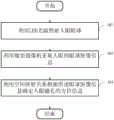
图2为本发明具体实施方式提供的一种用于头戴式可视设备的人眼追踪方法的实施例一的流程图,如图2所示,LED光源开启瞬间,微型摄像机采集人眼的眼球图像信息,通过分析采集的眼球图像信息确定人眼瞳孔的方位信息。FIG. 2 is a flow chart of Embodiment 1 of a method for eye tracking for a head-mounted visual device provided by specific embodiments of the present invention. As shown in FIG. 2 , the moment the LED light source is turned on, the micro camera collects the human eye Eyeball image information, the orientation information of the pupil of the human eye is determined by analyzing the collected eyeball image information.
该附图所示的具体实施方式包括:The specific implementation shown in this drawing includes:
步骤101:利用LED光源照射人眼眼球。LED光源类似照相机的闪光灯,开启后立刻关闭,不会影响用户正常视觉体验。Step 101 : irradiating the human eyeball with an LED light source. The LED light source is similar to the flash of a camera, and it is turned off immediately after being turned on, which will not affect the normal visual experience of the user.
步骤102:利用微型摄像机采集人眼的眼球图像信息。微型摄像机在LED光源开启瞬间采集人眼的眼球图像信息;微型摄像机可以为微型摄像机、微型照相机等。Step 102: Collect eyeball image information of the human eye by using a miniature camera. The micro camera collects the eyeball image information of the human eye when the LED light source is turned on; the micro camera can be a micro camera, a micro camera, or the like.
步骤103:利用空间映射关系根据所述眼球图像信息确定人眼瞳孔的方位信息。本发明的具体实施例中,具步骤103体包括:采集左眼的眼球图像信息和右眼的眼球图像信息;根据左眼的眼球图像信息获得左眼注视方位的左眼光轴矢量,并根据右眼的眼球图像信息获得右眼注视方位的右眼光轴矢量;根据所述左眼光轴矢量和所述右眼光轴矢量确定人眼瞳孔的方位信息。Step 103: Determine the orientation information of the pupil of the human eye according to the eyeball image information by using the spatial mapping relationship. In a specific embodiment of the present invention, the
参见图2,利用微型摄像机(还可以利用微型照相机等传感器)采集人眼的眼球图像信息,根据空间映射关系对获取的眼球图像信息进行分析,可实时获取瞳孔聚焦区域,从而确定用户的观看方位,不增加头戴式可视设备的重量,而且不会泄露用户周围的环境信息,提高用户体验度。Referring to Figure 2, the eyeball image information of the human eye is collected by a micro camera (or a sensor such as a micro camera), and the obtained eyeball image information is analyzed according to the spatial mapping relationship, and the pupil focus area can be obtained in real time, so as to determine the user's viewing orientation. , does not increase the weight of the head-mounted visual device, and does not leak environmental information around the user, improving the user experience.
图3为本发明具体实施方式提供的一种用于头戴式可视设备的人眼追踪方法的实施例二的流程图,如图3所示,在对用户进行人眼追踪之前,需要利用三维矩阵构建微型摄像机、参考点以及人眼眼球之间的空间映射关系。FIG. 3 is a flowchart of Embodiment 2 of a method for eye tracking for a head-mounted visual device provided by a specific embodiment of the present invention. As shown in FIG. 3 , before performing eye tracking on a user, it is necessary to use The three-dimensional matrix constructs the spatial mapping relationship between the miniature camera, the reference point and the human eye.
该附图所示的具体实施方式中,步骤101之前,该方法还包括:In the specific embodiment shown in the figure, before
步骤100:利用三维矩阵构建微型摄像机、参考点以及人眼眼球之间的空间映射关系。Step 100: Use a three-dimensional matrix to construct a spatial mapping relationship between the miniature camera, the reference point and the human eyeball.
参见图3,以不同的函数形式、三维矩阵形式来拟合人眼眼球所在的坐标系、参考点所在的坐标系之间一一对应的映射关系,以及微型摄像机与人眼眼球之间的位置关系,最终构建微型摄像机、参考点以及人眼眼球之间的空间映射关系,利用空间映射关系结合采集的眼球图像信息可以实时计算出使用者在虚拟空间中的视觉凝视点。Referring to Figure 3, different functional forms and three-dimensional matrix forms are used to fit the one-to-one mapping relationship between the coordinate system where the human eyeball is located, the coordinate system where the reference point is located, and the position between the micro camera and the human eyeball Finally, the spatial mapping relationship between the micro-camera, the reference point and the human eyeball is constructed, and the user's visual gaze point in the virtual space can be calculated in real time by using the spatial mapping relationship combined with the collected eyeball image information.
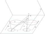
图4为本发明具体实施方式提供的微型摄像机、参考点以及人眼眼球之间的空间位置关系三维坐标示意图,如图4所示,本发明提供一种应用于虚拟现实头盔的瞳孔聚焦区域追踪方案,主要通过在头戴式可视设备(例如,虚拟现实头盔)镜片两侧安装微型摄像机(例如,微型摄像机),并在微型摄像机镜头边缘安装LED光源,借助虚拟现实头盔的工作特性在虚拟场景中设置4个参考点,人眼眼球在注视参考点时,开启LED光源,微型摄像机捕捉并记录眼球及瞳孔的实时图像信息,然后再结合微型摄像机、参考点以及人眼眼球所在坐标系的空间位置关系,以不同的函数形式、矩阵形式来拟合眼图参考系与参考点所在的参考系之间的一一对应映射关系,得出瞳孔位置及其方位信息,进而可计算出空间中任一视觉凝视点的位置坐标,该系统空间位置关系如图4所示,图中E1和E2为左右眼球所在空间直角坐标系原点;S1和S2为微型摄像机所在空间直角坐标系原点;O为目标注视点所在的空间直角坐标系原点;X1和X2为虚拟现实中设置的参考点,X1和X2位于两眼球所在线段的中垂线上;X3为虚拟现实场景中的目标注视点;H1、H2和Ct为摄像机与人眼的垂直距离;L为两眼球之间的距离;Cs为两个微型摄像机之间的距离;参考点X1和X2之间的距离,与参考点X1与S0之间的距离相等,均为ΔX;∠E1X1E2的角度为2θ。FIG. 4 is a schematic diagram of three-dimensional coordinates of the spatial positional relationship between a miniature camera, a reference point and a human eye according to a specific embodiment of the present invention. As shown in FIG. 4 , the present invention provides a pupil focus area tracking applied to a virtual reality helmet The solution is mainly by installing miniature cameras (eg, miniature cameras) on both sides of the lens of the head-mounted visual device (eg, virtual reality helmet), and installing LED light sources on the edge of the lens of the miniature camera. Four reference points are set in the scene. When the human eyeball is looking at the reference point, the LED light source is turned on, and the micro camera captures and records the real-time image information of the eyeball and pupil, and then combines the micro camera, the reference point and the coordinate system where the human eyeball is located. Spatial positional relationship, using different functional forms and matrix forms to fit the one-to-one mapping relationship between the eye diagram reference frame and the reference frame where the reference point is located, to obtain the pupil position and its orientation information, and then to calculate the spatial The position coordinates of any visual gaze point, the spatial positional relationship of the system is shown in Figure 4. In the figure, E1 and E2 are the origin of the spatial Cartesian coordinate system where the left and right eyeballs are located; S1 and S2 are the origin of the spatial Cartesian coordinate system where the micro camera is located; O is The origin of the spatial Cartesian coordinate system where the target gaze point is located; X1 and X2 are the reference points set in the virtual reality, and X1 and X2 are located on the vertical line of the line segment where the two eyeballs are located; X3 is the target gaze point in the virtual reality scene; H1 , H2 and Ct are the vertical distance between the camera and the human eye; L is the distance between the two eyeballs; Cs is the distance between the two miniature cameras; the distance between the reference points X1 and X2, and the reference point X1 and S0 The distance between them is equal, both are ΔX; the angle of ∠E1X1E2 is 2θ.
基于图4所示的不同坐标系(人眼眼球坐标系E、摄像机所在坐标系S、参考点所在坐标系O)之间的转换关系及空间位置关系,计算得出瞳孔的空间位置及方位信息,即可得到瞳孔注视某一点的矢量坐标。其中瞳孔的空间位置可表示为


(1)绕X轴旋转:y'=ycost-zsint(1) Rotate around the X axis: y'=ycost-zsint
z'=ysint+zcostz'=ysint+zcost
x'=xx'=x
其中,
(2)绕Z轴旋转:x'=xcost-ysint(2) Rotate around the Z axis: x'=xcost-ysint
y'=xsint+ycosty'=xsint+ycost
z'=zz'=z
其中,
(3)由(1)、(2)可以确定R的值:(3) The value of R can be determined from (1) and (2):

通过参考点的标定,获取该系统中的未知参数,然后实时计算出各瞳孔在注视任一点的方位及位置坐标信息[R,t],即:Through the calibration of the reference point, the unknown parameters in the system are obtained, and then the orientation and position coordinate information [R, t] of each pupil at any point of the gaze is calculated in real time, namely:

1.坐标系的转换:1. Conversion of coordinate system:
参考点X1、X2所在坐标系记为平面坐标系O,眼球所在坐标系记为眼三维坐标系E,摄像机所在的坐标系记为S,摄像机拍摄眼球运动的二维图像所在的坐标系记为B,根据虚拟现实眼动追踪系统中摄像机、参考点以及眼球所在坐标系的关系,可得如图5所示的坐标转换关系图。The coordinate system where the reference points X1 and X2 are located is recorded as the plane coordinate system O, the coordinate system where the eyeball is located is recorded as the eye three-dimensional coordinate system E, the coordinate system where the camera is located is recorded as S, the coordinate system where the camera captures the two-dimensional image of eye movement is located Denoted as B, according to the relationship between the camera, the reference point and the coordinate system where the eyeball is located in the virtual reality eye tracking system, the coordinate conversion diagram as shown in Figure 5 can be obtained.
在等式TO←E=TO←S·TS←B·TB←E中,TO←E代表从眼坐标系E到参考点所在坐标系O的转换关系,通过参考点标定可获取,另TO←S摄像机所在坐标系S相对于参考点所在坐标系O,以及TS←B摄像机所拍摄的二维图像所在坐标系B相对于摄像机所在坐标系S,都可通过标定获取。In the equation TO←E = TO←S · TS←B · TB←E , TO←E represents the conversion relationship from the eye coordinate system E to the coordinate system O where the reference point is located. Obtain, the coordinate system S where the TO←S camera is located relative to the coordinate system O where the reference point is located, and the coordinate system B where the two-dimensional image captured by the TS←B camera is located relative to the coordinate system S where the camera is located, can be obtained by calibration. .
TB←E:根据参考点计算出TB←E中的两个未知参数(x,y),即当前眼坐标系E与二维图像所在坐标系B之间的变换关系。眼球相对于眼眶是有两个未知的量,在眼眶及眼球形状限制下,眼球只能在X、Y轴进行运动,通过参考点的标定可求得TB←E中的两个未知量,获取TB←E的转换关系。TB←E : Calculate the two unknown parameters (x, y) in TB ←E according to the reference point, that is, the transformation relationship between the current eye coordinate system E and the coordinate system B where the two-dimensional image is located. The eyeball has two unknown quantities relative to the orbit. Under the constraints of the orbit and the shape of the eyeball, the eyeball can only move in the X and Y axes. The two unknown quantities in TB←E can be obtained by the calibration of the reference point. Get the transformation relation of TB←E .
通过参考点的标定,同时根据坐标系转换关系,可计算得出坐标系的未知参数。Through the calibration of the reference point and the transformation relationship of the coordinate system, the unknown parameters of the coordinate system can be calculated.
2.基于三维矩阵的映射关系:2. Mapping relationship based on three-dimensional matrix:
首先确定三维空间中的点M=[X Y Z]T与二维空间中的点的图像坐标m=[x y]T之间的映射关系如下:First, determine the mapping relationship between the point M=[XYZ]T in the three-dimensional space and the image coordinates m=[xy]T of the point in the two-dimensional space as follows:

其中,R是一个3×3的旋转矩阵,t是一个3×1的向量,C是内部矩阵。瞳孔的4个外部参数确定了瞳孔相对于场景的位置和方位,其中包括两个旋转角,这两个旋转角可以唯一的确定R,另外两个参数即构成t。C中四个内部参数,起始点(x0,y0)代表光轴和参考点的交点处的像素坐标,fx和fy分别代表水平方位和垂直方位上焦点的长度。where R is a 3×3 rotation matrix, t is a 3×1 vector, and C is the inner matrix. Four external parameters of the pupil determine the position and orientation of the pupil relative to the scene, including two rotation angles, which can uniquely determine R, and the other two parameters constitute t. The four internal parameters in C, the starting point (x0 , y0 ) represents the pixel coordinates at the intersection of the optical axis and the reference point, and fx and fy represent the length of the focal point in the horizontal and vertical directions, respectively.
(3)根据上述方法,即可将摄像机拍摄的眼球二维图像转换成眼睛注视方位的光轴矢量坐标,两个眼睛所获取的光轴矢量相交处即是目标注视区域,在这里主要有以下三种情况:(3) According to the above method, the two-dimensional image of the eyeball captured by the camera can be converted into the optical axis vector coordinates of the gaze orientation of the eye, and the intersection of the optical axis vectors obtained by the two eyes is the target gaze area, which mainly includes the following three conditions:
第一种:光轴相交。得到的两个眼睛的光轴矢量成功相交,得到目标注视点The first: the optical axis intersects. The obtained optical axis vectors of the two eyes intersect successfully, and the target fixation point is obtained
第二种:光柱相交。根据每个使用者的眼球特征,形成以光轴矢量Fo为中心,r(根据使用者眼部特征可得)为半径的光柱,左右眼光柱相交处即为目标注视区域。The second: the beam of light intersects. According to the eyeball characteristics of each user, a beam of light is formed with the optical axis vector Fo as the center and r (obtained according to the user's eye characteristics) as the radius, and the intersection of the left and right eye beams is the target gaze area.
第三种:光锥相交。实际的视线几何范围是以视网膜为光锥顶点,以视线为光锥中轴线,成一定角度的光锥,即视野为所视焦平面上的一片区域。而区域的交叉区域即为视焦区域,视焦区域的几何中心为即为焦点。对于近视场光源,前两种方法可得到足够的近似精度。The third type: the intersection of light cones. The actual geometric range of sight line is that the retina is the vertex of the light cone, the line of sight is the central axis of the light cone, and the light cone at a certain angle, that is, the field of view is an area on the focal plane. The intersection area of the area is the focal area, and the geometric center of the focal area is the focal point. For near-field light sources, the first two methods yield adequate approximation accuracy.
通过在虚拟现实头盔安装摄像机和LED光源,在虚拟场景中设置参考点的方式拾取瞳孔在聚焦不同目标点的眼球图像数据,通过系统的空间位置关系、不同坐标系之间的转换及图像数据,计算出使用者瞳孔实时位置及聚焦方位,即可实时计算出使用者在虚拟空间中的视觉凝视点。By installing a camera and LED light source on the virtual reality helmet, and setting reference points in the virtual scene, the eyeball image data of the pupil focusing on different target points is picked up. Through the spatial position relationship of the system, the conversion between different coordinate systems and the image data, By calculating the real-time position and focus orientation of the user's pupil, the user's visual gaze point in the virtual space can be calculated in real time.
本发明方案主要包含以下几点的内容:虚拟现实头盔边缘摄像机及LED光源的设置;虚拟现实场景中参考点的设置;拍照记录瞳孔运动图像;根据图像信息分割眼白与瞳孔得出瞳孔与眼球的位置关系;根据获取的数据计算瞳孔的实时位置及聚焦方位。The solution of the present invention mainly includes the following points: setting of the edge camera and LED light source of the virtual reality helmet; setting of the reference point in the virtual reality scene; photographing and recording the moving image of the pupil; Position relationship; calculate the real-time position and focus orientation of the pupil according to the acquired data.
硬件方面:在虚拟现实头盔的镜片边缘位置各设置一个微型摄像机用来捕捉使用者眼球的变化情况。同时在微型摄像机上再各设置一个LED光源用来发射光,帮助摄像机进行数据采集,微型摄像机位置关系如图4所示。In terms of hardware: a miniature camera is set at the edge of the lens of the virtual reality helmet to capture the changes of the user's eyeballs. At the same time, an LED light source is set on each of the miniature cameras to emit light to help the camera to collect data. The positional relationship of the miniature cameras is shown in Figure 4.
设置参考点:在使用者使用虚拟现实头盔之前,在默认虚拟场景中由近至远设置4个目标点作为参考点,设置参考点是为了获取眼睛聚焦参考点时的数据信息,使用者瞳孔聚焦一个参考点时,摄像机就会捕捉到此时使用者的眼球图像信息,通过对图像信息的解析获得一组数据,不同参考点也就能获得不同数据。Set reference points: Before the user uses the virtual reality helmet, set 4 target points as reference points from near to far in the default virtual scene. The purpose of setting the reference points is to obtain the data information when the eyes focus on the reference point. When there is a reference point, the camera will capture the user's eyeball image information at this time, and obtain a set of data by analyzing the image information, and different reference points can also obtain different data.
摄像机拍照记录眼球运动图像:在使用者眼睛注视每个参考点的时候,开启LED灯,摄像机拍摄一组图像记录瞳孔运动信息,获得图像数据。The camera takes pictures to record eye movement images: when the user's eyes are gazing at each reference point, turn on the LED light, and the camera shoots a set of images to record pupil movement information and obtain image data.
解析图像信息获取瞳孔与眼球空间位置关系:将摄像机拍摄的不同组图像信息传至服务器端,通过图像解析分割眼白与瞳孔。Analyze the image information to obtain the spatial position relationship between the pupil and the eyeball: send different sets of image information captured by the camera to the server, and segment the white of the eye and the pupil through image analysis.
根据系统中各部分的空间位置关系、不同坐标系之间的关系,借助相关参考点的设置,以不同的函数形式、矩阵形式来拟合眼图参考系与参考点所在参考系之间一一对应的映射关系,得出瞳孔位置及其方位信息,进而实时计算出使用者在虚拟空间中的视觉凝视点。According to the spatial position relationship of each part in the system and the relationship between different coordinate systems, with the help of the setting of relevant reference points, the eye diagram reference system and the reference system where the reference point is located are fitted in different functional forms and matrix forms one by one. According to the corresponding mapping relationship, the pupil position and its orientation information are obtained, and then the user's visual gaze point in the virtual space is calculated in real time.
本发明至少还具有以下有效效果或特点:The present invention also has the following effective effects or features at least:
本发明应用环境为虚拟现实浸入式头盔内部的眼动追踪技术,近场眼球视线的几何近视,应用环境为除眼部空间外没有其他内容追踪的环境,该环境为保护用户的个人信息可控的(而不泄露用户周围环境)交互,方便使用;由于采用几何视线近视模型,而并未计算用户的晶状体、瞳孔、角膜、玻璃体等视觉光路重建参数模型,数据计算量小,实现简单。The application environment of the invention is the eye tracking technology inside the virtual reality immersion helmet, the geometric myopia of the near-field eye sight, the application environment is the environment without other content tracking except the eye space, and the environment is controllable to protect the user's personal information (without revealing the user's surrounding environment) interaction, easy to use; because the geometric line of sight myopia model is used, and the user's lens, pupil, cornea, vitreous and other visual optical path reconstruction parameter models are not calculated, the amount of data calculation is small, and the implementation is simple.
上述的本发明实施例可在各种硬件、软件编码或两者组合中进行实施。例如,本发明的实施例也可为在数据信号处理器(Digital Signal Processor,DSP)中执行上述方法的程序代码。本发明也可涉及计算机处理器、数字信号处理器、微处理器或现场可编程门阵列(Field Programmable Gate Array,FPGA)执行的多种功能。可根据本发明配置上述处理器执行特定任务,其通过执行定义了本发明揭示的特定方法的机器可读软件代码或固件代码来完成。可将软件代码或固件代码发展为不同的程序语言与不同的格式或形式。也可为不同的目标平台编译软件代码。然而,根据本发明执行任务的软件代码与其他类型配置代码的不同代码样式、类型与语言不脱离本发明的精神与范围。The above-described embodiments of the present invention may be implemented in various hardware, software encodings, or a combination of both. For example, the embodiments of the present invention can also be program codes for executing the above method in a digital signal processor (Digital Signal Processor, DSP). The present invention may also relate to various functions performed by computer processors, digital signal processors, microprocessors, or Field Programmable Gate Arrays (FPGAs). The above-described processors may be configured in accordance with the present invention to perform specific tasks by executing machine-readable software code or firmware code that defines the specific methods disclosed by the present invention. The software code or firmware code may be developed into different programming languages and different formats or forms. Software code can also be compiled for different target platforms. However, different code styles, types and languages of software code and other types of configuration code to perform tasks in accordance with the present invention do not depart from the spirit and scope of the present invention.
以上所述仅为本发明示意性的具体实施方式,在不脱离本发明的构思和原则的前提下,任何本领域的技术人员所做出的等同变化与修改,均应属于本发明保护的范围。The above description is only an exemplary embodiment of the present invention, without departing from the concept and principle of the present invention, any equivalent changes and modifications made by those skilled in the art shall fall within the protection scope of the present invention .
Claims (9)
Translated fromChinesePriority Applications (1)
| Application Number | Priority Date | Filing Date | Title |
|---|---|---|---|
| CN201610947348.0ACN107991775B (en) | 2016-10-26 | 2016-10-26 | Head-mounted visual device capable of human eye tracking and human eye tracking method |
Applications Claiming Priority (1)
| Application Number | Priority Date | Filing Date | Title |
|---|---|---|---|
| CN201610947348.0ACN107991775B (en) | 2016-10-26 | 2016-10-26 | Head-mounted visual device capable of human eye tracking and human eye tracking method |
Publications (2)
| Publication Number | Publication Date |
|---|---|
| CN107991775A CN107991775A (en) | 2018-05-04 |
| CN107991775Btrue CN107991775B (en) | 2020-06-05 |
Family
ID=62029017
Family Applications (1)
| Application Number | Title | Priority Date | Filing Date |
|---|---|---|---|
| CN201610947348.0AActiveCN107991775B (en) | 2016-10-26 | 2016-10-26 | Head-mounted visual device capable of human eye tracking and human eye tracking method |
Country Status (1)
| Country | Link |
|---|---|
| CN (1) | CN107991775B (en) |
Families Citing this family (10)
| Publication number | Priority date | Publication date | Assignee | Title |
|---|---|---|---|---|
| US11086124B2 (en)* | 2018-06-13 | 2021-08-10 | Reavire, Inc. | Detecting velocity state of a device |
| CN109522789A (en)* | 2018-09-30 | 2019-03-26 | 北京七鑫易维信息技术有限公司 | Eyeball tracking method, apparatus and system applied to terminal device |
| TWI725351B (en)* | 2018-11-02 | 2021-04-21 | 宏正自動科技股份有限公司 | Electronic device and output image determination method |
| TWI674518B (en)* | 2018-11-28 | 2019-10-11 | 國立臺灣大學 | Calibration method of eye-tracking and device thereof |
| US11200656B2 (en)* | 2019-01-11 | 2021-12-14 | Universal City Studios Llc | Drop detection systems and methods |
| CN110275304A (en)* | 2019-06-17 | 2019-09-24 | 上海宇极文化传播有限公司 | A kind of XR aobvious and the adjustment XR aobvious middle visual fields for playing image method |
| CN112381735B (en)* | 2020-11-16 | 2022-04-05 | 吉林大学 | A method of homogenizing the pixel coordinate system of the AOI boundary point of the head-mounted eye tracker |
| CN112926521B (en)* | 2021-03-30 | 2023-01-24 | 青岛小鸟看看科技有限公司 | Eyeball tracking method and system based on light source on-off |
| CN115343849B (en)* | 2021-05-13 | 2025-09-23 | 中强光电股份有限公司 | Light field near-eye display device and light field near-eye display method |
| CN116338960B (en)* | 2023-02-20 | 2025-09-19 | 北京理工大学 | Auxiliary wearing additional module and method for head-mounted display |
Citations (4)
| Publication number | Priority date | Publication date | Assignee | Title |
|---|---|---|---|---|
| CN102662476A (en)* | 2012-04-20 | 2012-09-12 | 天津大学 | Gaze estimation method |
| CN102830793A (en)* | 2011-06-16 | 2012-12-19 | 北京三星通信技术研究有限公司 | Sight tracking method and sight tracking device |
| US8885882B1 (en)* | 2011-07-14 | 2014-11-11 | The Research Foundation For The State University Of New York | Real time eye tracking for human computer interaction |
| CN105138965A (en)* | 2015-07-31 | 2015-12-09 | 东南大学 | Near-to-eye sight tracking method and system thereof |
Family Cites Families (8)
| Publication number | Priority date | Publication date | Assignee | Title |
|---|---|---|---|---|
| JP2005253778A (en)* | 2004-03-12 | 2005-09-22 | Gen Tec:Kk | Gaze detection method and apparatus |
| CN202533867U (en)* | 2012-04-17 | 2012-11-14 | 北京七鑫易维信息技术有限公司 | Head mounted eye-control display terminal |
| EP2893388B1 (en)* | 2012-09-03 | 2016-08-03 | SensoMotoric Instruments Gesellschaft für innovative Sensorik mbH | Head mounted system and method to compute and render a stream of digital images using a head mounted system |
| CN103793045B (en)* | 2012-10-31 | 2016-12-28 | 原相科技股份有限公司 | pupil tracking device |
| GB201305726D0 (en)* | 2013-03-28 | 2013-05-15 | Eye Tracking Analysts Ltd | A method for calibration free eye tracking |
| CN104090659B (en)* | 2014-07-08 | 2017-04-05 | 重庆金瓯科技发展有限责任公司 | Operating pointer based on eye image and Eye-controlling focus indicates control device |
| US9791924B2 (en)* | 2014-12-23 | 2017-10-17 | Mediatek Inc. | Eye tracking with mobile device in a head-mounted display |
| CN105929963B (en)* | 2016-05-11 | 2019-04-30 | 北京蚁视科技有限公司 | It is a kind of for tracking the method and detection device of eyeball position |
- 2016
- 2016-10-26CNCN201610947348.0Apatent/CN107991775B/enactiveActive
Patent Citations (4)
| Publication number | Priority date | Publication date | Assignee | Title |
|---|---|---|---|---|
| CN102830793A (en)* | 2011-06-16 | 2012-12-19 | 北京三星通信技术研究有限公司 | Sight tracking method and sight tracking device |
| US8885882B1 (en)* | 2011-07-14 | 2014-11-11 | The Research Foundation For The State University Of New York | Real time eye tracking for human computer interaction |
| CN102662476A (en)* | 2012-04-20 | 2012-09-12 | 天津大学 | Gaze estimation method |
| CN105138965A (en)* | 2015-07-31 | 2015-12-09 | 东南大学 | Near-to-eye sight tracking method and system thereof |
Also Published As
| Publication number | Publication date |
|---|---|
| CN107991775A (en) | 2018-05-04 |
Similar Documents
| Publication | Publication Date | Title |
|---|---|---|
| CN107991775B (en) | Head-mounted visual device capable of human eye tracking and human eye tracking method | |
| WO2018076202A1 (en) | Head-mounted display device that can perform eye tracking, and eye tracking method | |
| KR102062658B1 (en) | Sphere tracking of the cornea to create an ocular model | |
| US10037076B2 (en) | Gesture-driven modifications of digital content shown by head-mounted displays | |
| CN104244807B (en) | Gaze point detection device and gaze point detection method | |
| US9690099B2 (en) | Optimized focal area for augmented reality displays | |
| US10055889B2 (en) | Automatic focus improvement for augmented reality displays | |
| US9727132B2 (en) | Multi-visor: managing applications in augmented reality environments | |
| KR102144040B1 (en) | Face and eye tracking and facial animation using the head mounted display's face sensor | |
| US20160131902A1 (en) | System for automatic eye tracking calibration of head mounted display device | |
| US10819898B1 (en) | Imaging device with field-of-view shift control | |
| CN111630478A (en) | High-speed interlaced binocular tracking system | |
| US20240248527A1 (en) | Mixed reality interaction with eye-tracking techniques | |
| CN112753037A (en) | Sensor fusion eye tracking | |
| WO2020215960A1 (en) | Method and device for determining area of gaze, and wearable device | |
| CN111367405A (en) | Adjustment method, device, computer equipment and storage medium of head-mounted display device | |
| WO2022205770A1 (en) | Eyeball tracking system and method based on light field perception | |
| JP2019021049A (en) | Information processing apparatus, information processing method, and program | |
| CN108604015B (en) | Image display method and head mounted display device | |
| US20240403080A1 (en) | Devices, methods, and graphical user interfaces for displaying views of physical locations | |
| CN114581514B (en) | Method for determining binocular gaze points and electronic device | |
| US20250281085A1 (en) | Systems and methods for performing a motor skills neurological test using augmented or virtual reality | |
| US20250110569A1 (en) | Devices, Methods, and Graphical User Interfaces for Processing Inputs to a Three-Dimensional Environment | |
| KR20240066934A (en) | Wearable device, and method for transmitting information of user wearing wearable device | |
| JP2015013011A (en) | Visual field restriction image data creation program and visual field restriction apparatus using the same |
Legal Events
| Date | Code | Title | Description |
|---|---|---|---|
| PB01 | Publication | ||
| PB01 | Publication | ||
| SE01 | Entry into force of request for substantive examination | ||
| SE01 | Entry into force of request for substantive examination | ||
| GR01 | Patent grant | ||
| GR01 | Patent grant |