CN107982621B - Sputum suction tube - Google Patents
Sputum suction tubeDownload PDFInfo
- Publication number
- CN107982621B CN107982621BCN201711393050.0ACN201711393050ACN107982621BCN 107982621 BCN107982621 BCN 107982621BCN 201711393050 ACN201711393050 ACN 201711393050ACN 107982621 BCN107982621 BCN 107982621B
- Authority
- CN
- China
- Prior art keywords
- optical fiber
- plug
- tube
- seat
- control unit
- Prior art date
- Legal status (The legal status is an assumption and is not a legal conclusion. Google has not performed a legal analysis and makes no representation as to the accuracy of the status listed.)
- Active
Links
- 206010036790Productive coughDiseases0.000titleclaimsabstractdescription51
- 208000024794sputumDiseases0.000titleclaimsabstractdescription51
- 210000003802sputumAnatomy0.000titleclaimsabstractdescription51
- 239000013307optical fiberSubstances0.000claimsabstractdescription44
- 230000003287optical effectEffects0.000claimsabstractdescription8
- 238000005259measurementMethods0.000claimsdescription9
- 210000004877mucosaAnatomy0.000claimsdescription9
- 206010062717Increased upper airway secretionDiseases0.000claimsdescription4
- 208000026435phlegmDiseases0.000claimsdescription4
- WABPQHHGFIMREM-UHFFFAOYSA-Nlead(0)Chemical compound[Pb]WABPQHHGFIMREM-UHFFFAOYSA-N0.000claimsdescription2
- 238000010586diagramMethods0.000description2
- 230000008878couplingEffects0.000description1
- 238000010168coupling processMethods0.000description1
- 238000005859coupling reactionMethods0.000description1
- 230000007423decreaseEffects0.000description1
- 239000000835fiberSubstances0.000description1
- 238000003780insertionMethods0.000description1
- 230000037431insertionEffects0.000description1
- 238000000034methodMethods0.000description1
- 210000004400mucous membraneAnatomy0.000description1
Images


Classifications
- A—HUMAN NECESSITIES
- A61—MEDICAL OR VETERINARY SCIENCE; HYGIENE
- A61M—DEVICES FOR INTRODUCING MEDIA INTO, OR ONTO, THE BODY; DEVICES FOR TRANSDUCING BODY MEDIA OR FOR TAKING MEDIA FROM THE BODY; DEVICES FOR PRODUCING OR ENDING SLEEP OR STUPOR
- A61M25/00—Catheters; Hollow probes
- A61M25/0021—Catheters; Hollow probes characterised by the form of the tubing
- A—HUMAN NECESSITIES
- A61—MEDICAL OR VETERINARY SCIENCE; HYGIENE
- A61M—DEVICES FOR INTRODUCING MEDIA INTO, OR ONTO, THE BODY; DEVICES FOR TRANSDUCING BODY MEDIA OR FOR TAKING MEDIA FROM THE BODY; DEVICES FOR PRODUCING OR ENDING SLEEP OR STUPOR
- A61M25/00—Catheters; Hollow probes
- A61M25/0043—Catheters; Hollow probes characterised by structural features
- A—HUMAN NECESSITIES
- A61—MEDICAL OR VETERINARY SCIENCE; HYGIENE
- A61M—DEVICES FOR INTRODUCING MEDIA INTO, OR ONTO, THE BODY; DEVICES FOR TRANSDUCING BODY MEDIA OR FOR TAKING MEDIA FROM THE BODY; DEVICES FOR PRODUCING OR ENDING SLEEP OR STUPOR
- A61M2205/00—General characteristics of the apparatus
- A61M2205/33—Controlling, regulating or measuring
- A61M2205/3331—Pressure; Flow
- A61M2205/3334—Measuring or controlling the flow rate
- A—HUMAN NECESSITIES
- A61—MEDICAL OR VETERINARY SCIENCE; HYGIENE
- A61M—DEVICES FOR INTRODUCING MEDIA INTO, OR ONTO, THE BODY; DEVICES FOR TRANSDUCING BODY MEDIA OR FOR TAKING MEDIA FROM THE BODY; DEVICES FOR PRODUCING OR ENDING SLEEP OR STUPOR
- A61M2205/00—General characteristics of the apparatus
- A61M2205/58—Means for facilitating use, e.g. by people with impaired vision
- A61M2205/587—Lighting arrangements
- A—HUMAN NECESSITIES
- A61—MEDICAL OR VETERINARY SCIENCE; HYGIENE
- A61M—DEVICES FOR INTRODUCING MEDIA INTO, OR ONTO, THE BODY; DEVICES FOR TRANSDUCING BODY MEDIA OR FOR TAKING MEDIA FROM THE BODY; DEVICES FOR PRODUCING OR ENDING SLEEP OR STUPOR
- A61M2210/00—Anatomical parts of the body
- A61M2210/10—Trunk
- A61M2210/1025—Respiratory system
- A61M2210/1032—Trachea
- Y—GENERAL TAGGING OF NEW TECHNOLOGICAL DEVELOPMENTS; GENERAL TAGGING OF CROSS-SECTIONAL TECHNOLOGIES SPANNING OVER SEVERAL SECTIONS OF THE IPC; TECHNICAL SUBJECTS COVERED BY FORMER USPC CROSS-REFERENCE ART COLLECTIONS [XRACs] AND DIGESTS
- Y02—TECHNOLOGIES OR APPLICATIONS FOR MITIGATION OR ADAPTATION AGAINST CLIMATE CHANGE
- Y02A—TECHNOLOGIES FOR ADAPTATION TO CLIMATE CHANGE
- Y02A50/00—TECHNOLOGIES FOR ADAPTATION TO CLIMATE CHANGE in human health protection, e.g. against extreme weather
- Y02A50/30—Against vector-borne diseases, e.g. mosquito-borne, fly-borne, tick-borne or waterborne diseases whose impact is exacerbated by climate change
Landscapes
- Health & Medical Sciences (AREA)
- Life Sciences & Earth Sciences (AREA)
- Biophysics (AREA)
- Pulmonology (AREA)
- Engineering & Computer Science (AREA)
- Anesthesiology (AREA)
- Biomedical Technology (AREA)
- Heart & Thoracic Surgery (AREA)
- Hematology (AREA)
- Animal Behavior & Ethology (AREA)
- General Health & Medical Sciences (AREA)
- Public Health (AREA)
- Veterinary Medicine (AREA)
- External Artificial Organs (AREA)
Abstract
Description
Translated fromChinese技术领域technical field
本发明涉及一种医疗器械,尤其涉及一种吸痰管。The invention relates to a medical device, in particular to a sputum suction tube.
背景技术Background technique
目前,在使用吸痰管进行吸痰时,一般是盲插盲吸。经常会出现吸痰管的吸痰孔吸在患者的气道粘膜上,将气道粘膜吸破。At present, when using a sputum suction tube for sputum suction, it is generally blind insertion and blind suction. It often occurs that the suction hole of the suction tube is sucked on the patient's airway mucosa, and the airway mucosa is broken.
发明内容Contents of the invention
鉴于上述问题,本发明旨在提出一种能够分辨吸痰孔是不是吸到气道粘膜的吸痰管。In view of the above problems, the present invention aims to propose a sputum suction tube capable of distinguishing whether the sputum suction hole is sucked into the mucous membrane of the airway.
本发明的吸痰管,其包括管体和中空的座体,管体的第二端和座体的第一端气密性地且可插拔地结合在一起;The sputum suction tube of the present invention comprises a tube body and a hollow seat body, the second end of the tube body and the first end of the seat body are airtightly and pluggably combined;
管体内设置有光纤,光纤的第一端设置在管体的吸痰孔附近,第二端设置在管体的第二端并形成光纤插头;管体的第一端内设置有LED光源;LED光源的导线延伸至管体的第二端并形成LED插头;An optical fiber is arranged in the tube body, the first end of the optical fiber is set near the sputum suction hole of the tube body, and the second end is set at the second end of the tube body to form an optical fiber plug; the first end of the tube body is provided with an LED light source; The lead wire of the light source extends to the second end of the tube body and forms an LED plug;
座体的第一端形成光纤插头座,以结合光纤插头;座体的第一端还形成LED插头座,以结合LED插头;座体内进一步形成有控制单元、光纤收发单元,座体上表面设置有显示单元;光纤收发单元与光纤插头座连接,以接收光纤传输的光信号,并根据接收的光信号变换成电信号并发送给控制单元,控制单元根据接收的电信号在显示单元上显示图像;控制单元与LED插头座连接,以控制LED光源的点亮。The first end of the seat body forms an optical fiber plug seat to combine with the optical fiber plug; the first end of the seat body also forms an LED plug seat to combine with the LED plug; a control unit and an optical fiber transceiver unit are further formed in the seat body, and the upper surface of the seat body is set There is a display unit; the optical fiber transceiver unit is connected with the optical fiber plug socket to receive the optical signal transmitted by the optical fiber, and convert the received optical signal into an electrical signal and send it to the control unit, and the control unit displays the image on the display unit according to the received electrical signal ; The control unit is connected with the LED socket to control the lighting of the LED light source.
优选地,在管体的第一端环绕管体设置有电感器,至少电感器的一部分位于吸痰孔的下游,电感器的两端延伸至管体的第二端并形成电感插头;Preferably, an inductor is arranged around the first end of the tube body, at least a part of the inductor is located downstream of the suction hole, and both ends of the inductor extend to the second end of the tube body to form an inductance plug;
座体的第一端形成电感插头座,以结合电感插头;座体中进一步形成有电感测量电路;电感插头座连接于电感测量电路,电感测量电路连接于控制单元;The first end of the seat body forms an inductance plug seat to combine with the inductance plug; an inductance measurement circuit is further formed in the seat body; the inductance plug seat is connected to the inductance measurement circuit, and the inductance measurement circuit is connected to the control unit;
当吸痰孔中有痰液进入时,电感器的电感值增大。When sputum enters the phlegm suction hole, the inductance value of the inductor increases.
优选地,座体的中空部中形成有流量计,流量计与控制单元连接;Preferably, a flow meter is formed in the hollow part of the seat, and the flow meter is connected with the control unit;
当吸痰孔吸附在气道粘膜上时,流量计感测的流量值变小。When the suction hole is adsorbed on the airway mucosa, the flow value sensed by the flow meter becomes smaller.
优选地,座体的中空部中形成有流量计,流量计与控制单元连接;Preferably, a flow meter is formed in the hollow part of the seat, and the flow meter is connected with the control unit;
当吸痰孔吸入浓痰时,流量计感测的流量值变小而电感器的电感值增大。When thick phlegm is sucked into the sputum suction hole, the flow value sensed by the flow meter becomes smaller and the inductance value of the inductor increases.
优选地,所述吸痰孔位于电感器的两圈导线之间。Preferably, the sputum suction hole is located between two coils of wires of the inductor.
优选地,所述光纤的第一端朝向管体的外侧。Preferably, the first end of the optical fiber faces the outside of the tube body.
本发明的吸痰管形成分体式结构,并且设置了光纤、电感器、流量计,从三方面感测吸痰管是否在吸痰,一旦发生吸痰孔吸附在气道粘膜的情况,及时处理,避免气道粘膜破损发生。The sputum suction tube of the present invention forms a split structure, and is equipped with an optical fiber, an inductor, and a flow meter to sense whether the sputum suction tube is sucking sputum from three aspects. , to avoid damage to the airway mucosa.
附图说明Description of drawings
图1为本发明的吸痰管的第一实施例的结构示意图;Fig. 1 is the structural representation of the first embodiment of the sputum suction tube of the present invention;
图2为本发明的吸痰管的第二实施例的结构示意图;Fig. 2 is a schematic structural view of the second embodiment of the sputum suction tube of the present invention;
图3为本发明的吸痰管的管体的结构示意图;Fig. 3 is a schematic structural view of the tube body of the sputum suction tube of the present invention;
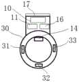
图4为本发明的吸痰管的座体的结构示意图;Fig. 4 is a schematic structural view of the base of the sputum suction tube of the present invention;
图5为图4的座体的侧面结构示意图;Fig. 5 is a schematic diagram of the side structure of the base of Fig. 4;
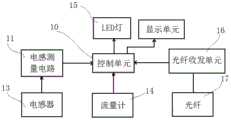
图6为本发明的吸痰管的电路部分的原理框图。Fig. 6 is a functional block diagram of the circuit part of the sputum suction tube of the present invention.
具体实施方式Detailed ways
下面,结合附图对本发明的吸痰管进行详细说明。Below, the sputum suction tube of the present invention will be described in detail with reference to the accompanying drawings.
本发明的吸痰管,其设计为分体式结构,包括管体20和中空的座体30,这样座体可以重复多次利用,管体20可以为一次性耗材。管体20至少在其第一端形成为透明的。管体20的第二端和座体30的第一端气密性地且可插拔地结合在一起。The sputum suction tube of the present invention is designed as a split structure, including a
管体20内设置有光纤16,光纤16的第一端设置在管体20的吸痰孔21附近,以观察吸痰孔附近的情况。光纤16的第二端设置在管体20的第二端并形成光纤插头23;管体20的第一端内设置有LED光源15,LED光源15为吸痰管插入患者气道时提供光源;LED光源15的导线延伸至管体20的第二端并形成LED插头。An
座体30的第二端用于连接负压源,其与现有的吸痰管与负压源连接的一端的结构相同,形成连接接头和负压调节孔。The second end of the
座体30的第一端形成光纤插头座33,以结合光纤插头23;座体30的第一端还形成LED插头座31,以结合LED插头;座体30内进一步形成有控制单元10、光纤收发单元16,座体上表面设置有显示单元17;光纤收发单元16与光纤插头座33连接,以接收光纤传输的光信号,并根据接收的光信号变换成电信号并发送给控制单元10,控制单元10根据接收的电信号在显示单元17上显示图像,由此使用者可以获知吸痰孔21附近的情况;控制单元10与LED插头座连31接,以控制LED光源的点亮。控制单元10通过单片机实现。The first end of the
在第二实施例中,在管体20的第一端环绕管体设置有电感器13,至少电感器13的一部分位于吸痰孔21的下游,由此经由吸痰孔21吸入的痰液会穿过电感器13而改变电感器13的电感值。电感器13的两端延伸至管体的第二端并形成电感插头22。In the second embodiment, an
座体30的第一端形成电感插头座32,以结合电感插头22。座体30中进一步形成有电感测量电路;电感插头座32连接于电感测量电路11,电感测量电路11连接于控制单元10,由此控制单元10可以获知是佛有痰液流经电感器,从侧面反映是否有痰液流过管体20。当吸痰孔中有痰液进入时,电感器的电感值增大。The first end of the
在第三实施例中,座体30的中空部中形成有流量计14,流量计14与控制10单元连接,由此控制单元10可以获知管体20中的流量大小。当吸痰孔吸附在气道粘膜上时,流量计感测的流量值变小。In the third embodiment, a
再将第二实施例与第三实施例相结合的第四实施例中,当吸痰孔21吸入浓痰时,流量计14感测的流量值变小而电感器13的电感值增大。In the fourth embodiment that combines the second embodiment with the third embodiment, when the
吸痰孔21可以是位于电感器的两圈导线之间。The
光纤16的第一端朝向管体的外侧,以方便观察与吸痰孔21正对的外部情况。The first end of the
在仅仅设有光纤的方式,可以通过光纤传导的图像来判断吸痰孔周围的情况,如果看到的是痰液,则表明是痰液被吸入;如果看到的是气道,可能对应两种情况,气道黏膜被吸附或者吸痰孔与气道壁有预定距离且气道壁上没有痰。为了区分这两种情况,可以通过流量计的流量来判断,如果流量很小,则可认为吸附到气道黏膜上。但是,还存在管体被浓痰堵塞的情况,此时从光纤的图像中有可能看不到痰液,而流量计也流量很小,但不能由此就判断是吸附到气道粘膜上,因为浓痰也会使得吸痰管堵塞,此时可通过电感器的电感值变化来判断是否是由于浓痰进入吸痰管而造成流量减小,排除虚警。In the way with only optical fiber, the situation around the suction hole can be judged through the image transmitted by the optical fiber. If you see sputum, it means that the sputum is inhaled; if you see the airway, it may correspond to two In this case, the airway mucosa is absorbed or there is a predetermined distance between the suction hole and the airway wall and there is no sputum on the airway wall. In order to distinguish these two situations, it can be judged by the flow rate of the flow meter. If the flow rate is small, it can be considered to be adsorbed on the airway mucosa. However, there are still cases where the tube body is blocked by thick sputum. At this time, the sputum may not be seen in the image of the optical fiber, and the flow rate of the flowmeter is also very small, but it cannot be judged that it is adsorbed on the airway mucosa. Because thick sputum will also block the suction tube, at this time, the change of inductance value of the inductor can be used to judge whether the flow rate is reduced due to thick sputum entering the suction tube, so as to eliminate false alarms.
Claims (3)
Translated fromChinesePriority Applications (1)
| Application Number | Priority Date | Filing Date | Title |
|---|---|---|---|
| CN201711393050.0ACN107982621B (en) | 2017-12-21 | 2017-12-21 | Sputum suction tube |
Applications Claiming Priority (1)
| Application Number | Priority Date | Filing Date | Title |
|---|---|---|---|
| CN201711393050.0ACN107982621B (en) | 2017-12-21 | 2017-12-21 | Sputum suction tube |
Publications (2)
| Publication Number | Publication Date |
|---|---|
| CN107982621A CN107982621A (en) | 2018-05-04 |
| CN107982621Btrue CN107982621B (en) | 2023-04-18 |
Family
ID=62039215
Family Applications (1)
| Application Number | Title | Priority Date | Filing Date |
|---|---|---|---|
| CN201711393050.0AActiveCN107982621B (en) | 2017-12-21 | 2017-12-21 | Sputum suction tube |
Country Status (1)
| Country | Link |
|---|---|
| CN (1) | CN107982621B (en) |
Families Citing this family (1)
| Publication number | Priority date | Publication date | Assignee | Title |
|---|---|---|---|---|
| CN109646004A (en)* | 2019-01-29 | 2019-04-19 | 黄世英 | A kind of sputum intelligent induction monitoring device |
Citations (2)
| Publication number | Priority date | Publication date | Assignee | Title |
|---|---|---|---|---|
| CN202236799U (en)* | 2011-08-29 | 2012-05-30 | 中国人民解放军第四军医大学 | External fixator for internal jugular vein catheter |
| CN105286787A (en)* | 2011-04-29 | 2016-02-03 | 美敦力公司 | Monitoring Fluid Volume for Patients with Renal Disease |
Family Cites Families (12)
| Publication number | Priority date | Publication date | Assignee | Title |
|---|---|---|---|---|
| CN2618607Y (en)* | 2003-05-20 | 2004-06-02 | 唐和平 | Medical electric suction device |
| JP4302090B2 (en)* | 2005-10-26 | 2009-07-22 | 株式会社徳永装器研究所 | Endotracheal fistula suction device |
| KR101509827B1 (en)* | 2007-03-19 | 2015-04-06 | 인슐린 메디컬 엘티디 | Method and device for drug delivery |
| CN201171812Y (en)* | 2007-12-29 | 2008-12-31 | 邓辉胜 | visual aspirator |
| GB2457469B (en)* | 2008-02-13 | 2012-11-07 | Probe Scient Ltd | Molecular exchange device |
| JP5436899B2 (en)* | 2009-03-23 | 2014-03-05 | テルモ株式会社 | Suction system |
| CN203458623U (en)* | 2013-05-08 | 2014-03-05 | 宁波卫生职业技术学院 | Phlegm-absorbing tube with function of illumination |
| CN105477741A (en)* | 2016-01-26 | 2016-04-13 | 南京信息工程大学 | Transfusion reminding device and method |
| CN105709282A (en)* | 2016-04-05 | 2016-06-29 | 中国人民解放军总医院 | Sputum suction catheter |
| KR20170113381A (en)* | 2017-03-30 | 2017-10-12 | (주)엘메카 | Catheter Guide Structure |
| CN107349481A (en)* | 2017-06-30 | 2017-11-17 | 鞠春芳 | A kind of multifunctional breath sputum aspirator |
| CN208405691U (en)* | 2017-12-21 | 2019-01-22 | 中国人民解放军总医院 | Sputum aspirator tube |
- 2017
- 2017-12-21CNCN201711393050.0Apatent/CN107982621B/enactiveActive
Patent Citations (2)
| Publication number | Priority date | Publication date | Assignee | Title |
|---|---|---|---|---|
| CN105286787A (en)* | 2011-04-29 | 2016-02-03 | 美敦力公司 | Monitoring Fluid Volume for Patients with Renal Disease |
| CN202236799U (en)* | 2011-08-29 | 2012-05-30 | 中国人民解放军第四军医大学 | External fixator for internal jugular vein catheter |
Also Published As
| Publication number | Publication date |
|---|---|
| CN107982621A (en) | 2018-05-04 |
Similar Documents
| Publication | Publication Date | Title |
|---|---|---|
| US20010017134A1 (en) | Conduit for connecting a fluid transfer device to a patient | |
| CN105392508B (en) | Breast pump unit | |
| CN110464966A (en) | A kind of Multifunctional stomach tube seal wire | |
| CN107982621B (en) | Sputum suction tube | |
| KR101527495B1 (en) | Laser leveling system | |
| US9044294B1 (en) | Dental suction adapter | |
| CN208405691U (en) | Sputum aspirator tube | |
| CN108742882A (en) | Absorption type tongue retractor | |
| CN205866715U (en) | Fill attraction platform | |
| WO2011128610A1 (en) | Video apparatus | |
| EP2992920A1 (en) | Respiratory device having function of detecting airflow pressure difference | |
| CN221555533U (en) | Tongue depressor accessory and soft visual laryngoscope | |
| CN206995234U (en) | The visual intubation endoscope systems of 3D | |
| CN211484481U (en) | Electronic endoscope | |
| CN213964562U (en) | Visual device, visual sputum suction tube and visual sputum suction tube system | |
| CN213251699U (en) | Low-stimulation sputum suction device for pediatric internal medicine | |
| CN209137666U (en) | A kind of tracheostomy tube | |
| TWM519484U (en) | Improved structure of miniature observation lens camera lens (2) | |
| CN219271846U (en) | Main unit and ventilation treatment equipment | |
| CN219462054U (en) | a suction device | |
| CN215741149U (en) | Trachea cannula capable of measuring temperature and sucking phlegm | |
| CN211357006U (en) | A Simple Visualized Double-lumen Sputum Suction Tube | |
| CN203315491U (en) | Simple breathing airflow sensing gauge | |
| CN110960735A (en) | Sputum suction tube and visual suction device | |
| CN212415688U (en) | Electronic fiberoptic nasopharyngoscope with secretion suction function |
Legal Events
| Date | Code | Title | Description |
|---|---|---|---|
| PB01 | Publication | ||
| PB01 | Publication | ||
| SE01 | Entry into force of request for substantive examination | ||
| SE01 | Entry into force of request for substantive examination | ||
| GR01 | Patent grant | ||
| GR01 | Patent grant |