CN107925533B - V2X performance enhancement in high speed environments - Google Patents
V2X performance enhancement in high speed environmentsDownload PDFInfo
- Publication number
- CN107925533B CN107925533BCN201580082655.0ACN201580082655ACN107925533BCN 107925533 BCN107925533 BCN 107925533BCN 201580082655 ACN201580082655 ACN 201580082655ACN 107925533 BCN107925533 BCN 107925533B
- Authority
- CN
- China
- Prior art keywords
- ofdm
- dmrs
- subframe
- fdma
- symbols
- Prior art date
- Legal status (The legal status is an assumption and is not a legal conclusion. Google has not performed a legal analysis and makes no representation as to the accuracy of the status listed.)
- Active
Links
Images


Classifications
- H—ELECTRICITY
- H04—ELECTRIC COMMUNICATION TECHNIQUE
- H04L—TRANSMISSION OF DIGITAL INFORMATION, e.g. TELEGRAPHIC COMMUNICATION
- H04L1/00—Arrangements for detecting or preventing errors in the information received
- H04L1/004—Arrangements for detecting or preventing errors in the information received by using forward error control
- H04L1/0056—Systems characterized by the type of code used
- H04L1/0067—Rate matching
- H04L1/0068—Rate matching by puncturing
- H04L1/0069—Puncturing patterns
- H—ELECTRICITY
- H04—ELECTRIC COMMUNICATION TECHNIQUE
- H04L—TRANSMISSION OF DIGITAL INFORMATION, e.g. TELEGRAPHIC COMMUNICATION
- H04L25/00—Baseband systems
- H04L25/02—Details ; arrangements for supplying electrical power along data transmission lines
- H04L25/0202—Channel estimation
- H04L25/0224—Channel estimation using sounding signals
- H—ELECTRICITY
- H04—ELECTRIC COMMUNICATION TECHNIQUE
- H04L—TRANSMISSION OF DIGITAL INFORMATION, e.g. TELEGRAPHIC COMMUNICATION
- H04L27/00—Modulated-carrier systems
- H04L27/26—Systems using multi-frequency codes
- H04L27/2601—Multicarrier modulation systems
- H04L27/2647—Arrangements specific to the receiver only
- H04L27/2655—Synchronisation arrangements
- H04L27/2668—Details of algorithms
- H04L27/2673—Details of algorithms characterised by synchronisation parameters
- H04L27/2675—Pilot or known symbols
- H—ELECTRICITY
- H04—ELECTRIC COMMUNICATION TECHNIQUE
- H04L—TRANSMISSION OF DIGITAL INFORMATION, e.g. TELEGRAPHIC COMMUNICATION
- H04L5/00—Arrangements affording multiple use of the transmission path
- H04L5/003—Arrangements for allocating sub-channels of the transmission path
- H04L5/0048—Allocation of pilot signals, i.e. of signals known to the receiver
- H04L5/0051—Allocation of pilot signals, i.e. of signals known to the receiver of dedicated pilots, i.e. pilots destined for a single user or terminal
- H—ELECTRICITY
- H04—ELECTRIC COMMUNICATION TECHNIQUE
- H04W—WIRELESS COMMUNICATION NETWORKS
- H04W4/00—Services specially adapted for wireless communication networks; Facilities therefor
- H04W4/30—Services specially adapted for particular environments, situations or purposes
- H04W4/40—Services specially adapted for particular environments, situations or purposes for vehicles, e.g. vehicle-to-pedestrians [V2P]
- H—ELECTRICITY
- H04—ELECTRIC COMMUNICATION TECHNIQUE
- H04B—TRANSMISSION
- H04B7/00—Radio transmission systems, i.e. using radiation field
- H04B7/02—Diversity systems; Multi-antenna system, i.e. transmission or reception using multiple antennas
- H04B7/04—Diversity systems; Multi-antenna system, i.e. transmission or reception using multiple antennas using two or more spaced independent antennas
- H04B7/0413—MIMO systems
Landscapes
- Engineering & Computer Science (AREA)
- Signal Processing (AREA)
- Computer Networks & Wireless Communication (AREA)
- Power Engineering (AREA)
- Mobile Radio Communication Systems (AREA)
Abstract
Description
Translated fromChinese相关申请Related applications
本申请要求于2015年9月24日递交的名为“V2V/V2X PERFORMANCE IN HIGH SPEEDENVIRONMENTS(高速环境中的V2V/V2X性能)”的美国临时申请No.62/232,388(律师存档号No.111027-IDF128282)的在35U.S.C.§119(e)下的优先权权益。This application claims US Provisional Application No. 62/232,388 (Attorney File No. 111027- IDF128282) under 35 U.S.C. §119(e).
背景技术Background technique
本公开的实施方式大体上可以涉及无线通信领域。更具体地,本公开中描述的实施方式涉及不同的第三代合作伙伴计划(3GPP)长期演进(LED)和长期演进高级(LTE-A)系统增强,以解决高移动性环境中的可靠V2X操作的问题并支持高移动性环境中的可靠V2X操作。描述了在高移动性车辆信道传播条件下改进V2X系统性能的若干方案。Embodiments of the present disclosure may relate generally to the field of wireless communications. More specifically, the embodiments described in this disclosure relate to different 3rd Generation Partnership Project (3GPP) Long Term Evolution (LED) and Long Term Evolution Advanced (LTE-A) system enhancements to address reliable V2X in high mobility environments operational issues and support reliable V2X operations in high mobility environments. Several schemes to improve the performance of V2X systems under high mobility vehicle channel propagation conditions are described.
附图说明Description of drawings
下面的详细描述参考附图。在不同附图中可以使用相同的参考标号来标识相同或相似的元件。The following detailed description refers to the accompanying drawings. The same reference numbers may be used in different drawings to identify the same or similar elements.
图1示出了本公开的第一方面的示例性子帧结构。FIG. 1 shows an exemplary subframe structure of the first aspect of the present disclosure.
图2示出了根据本公开的第一方面的示例实施方式的用于生成并发送通信信号的示例性(简化)发送路径。Figure 2 illustrates an exemplary (simplified) transmit path for generating and transmitting communication signals according to an exemplary implementation of the first aspect of the present disclosure.
图3示出了根据本公开的第一方面的示例实施方式的用于生成并发送通信信号的示例性(简化)流程图。Figure 3 shows an exemplary (simplified) flow diagram for generating and transmitting a communication signal according to an example implementation of the first aspect of the present disclosure.
图4示出了根据本公开的第一方面的示例实施方式的用于接收对应于子帧的通信信号的示例性(简化)接收路径。Figure 4 illustrates an exemplary (simplified) receive path for receiving a communication signal corresponding to a subframe according to an exemplary embodiment of the first aspect of the present disclosure.
图5示出了根据本公开的示例实施方式的用于接收对应于子帧的通信信号的示例性(简化)流程图。FIG. 5 shows an exemplary (simplified) flow diagram for receiving a communication signal corresponding to a subframe in accordance with an exemplary embodiment of the present disclosure.
图6示出了根据本公开的第二方面的示例实施方式的用于将DMRS映射到子帧并发送子帧的示例性(简化)流程图。Figure 6 shows an exemplary (simplified) flow diagram for mapping DMRS to subframes and transmitting the subframes according to an exemplary embodiment of the second aspect of the present disclosure.
图7-图13示出了根据本公开的第二方面的示例实施方式的利用不同DMRS映射图案的SL的子帧中的具有正常CP的OFDM/SC-FDMA符号的示例性结构。7-13 illustrate exemplary structures of OFDM/SC-FDMA symbols with normal CP in subframes of SLs utilizing different DMRS mapping patterns according to example embodiments of the second aspect of the present disclosure.
图14-图19示出了根据本公开的第二方面的示例实施方式的利用不同DMRS映射图案的SL的子帧中的具有扩展CP的OFDM/SC-FDMA符号的示例性结构。14-19 illustrate exemplary structures of OFDM/SC-FDMA symbols with extended CP in subframes of SLs utilizing different DMRS mapping patterns according to an example implementation of the second aspect of the present disclosure.
图20示出了根据本公开的第二方面的另一示例实施方式的用于将DMRS映射到子帧并发送子帧的另一示例性(简化)流程图。Figure 20 shows another exemplary (simplified) flow diagram for mapping DMRS to subframes and transmitting the subframes according to another exemplary embodiment of the second aspect of the present disclosure.
图21示出了根据本公开的第二方面的示例实施方式的用于将DMRS映射到子帧并发送子帧的另一示例性(简化)流程图。Figure 21 shows another exemplary (simplified) flow diagram for mapping DMRS to subframes and transmitting subframes according to an exemplary embodiment of the second aspect of the present disclosure.
图22示出了在通信设备处接收根据图20和图21的有关说明发送的通信信号并确定CFO的示例性流程图。22 illustrates an exemplary flow diagram for receiving, at a communication device, communication signals sent in accordance with the related descriptions of FIGS. 20 and 21 and determining CFO.
图23例示出了发送具有周期性图案中提供的DMRS符号的OFDM/SC-FDMA符号的效果。Figure 23 illustrates the effect of transmitting OFDM/SC-FDMA symbols with DMRS symbols provided in a periodic pattern.
图24示出了用于在携带DMRS的OFDM/SC-FDMA符号中对RE进行穿孔的两个示例性穿孔图案(1,0)和(0,1)。24 shows two exemplary puncturing patterns (1,0) and (0,1) for puncturing REs in OFDM/SC-FDMA symbols carrying DMRS.
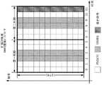
图25-图34示出了在假设符号的正常CP的情况下子帧中的不同示例性DMRS图案,每个指示针对不同DMRS图案的子帧中的两种可能的不同DMRS映射/穿孔图案(“位置1”和“位置2”指示不同的图案)。Figures 25-34 show different exemplary DMRS patterns in a subframe assuming normal CP for symbols, each indicating two possible different DMRS mapping/puncturing patterns in a subframe for a different DMRS pattern ("
图35-图41示出了在假设符号的扩展CP的情况下子帧中的不同示例性DMRS图案,每个指示针对不同DMRS图案的子帧中的两种可能的不同DMRS映射/穿孔图案(“位置1”和“位置2”指示不同的图案)。Figures 35-41 illustrate different exemplary DMRS patterns in a subframe assuming extended CP of symbols, each indicating two possible different DMRS mapping/puncturing patterns in a subframe for a different DMRS pattern ("
图42示出了根据本公开的第三方面的基于上述示例实施方式的示例性的基于UE的绝对载波频率估计的流程图。42 shows a flowchart of an exemplary UE-based absolute carrier frequency estimation based on the above-described exemplary embodiments according to a third aspect of the present disclosure.
图43示出了根据本公开的第三方面的由UE和eNB执行的、提供对UE的发送频率的上述eNB控制的调整的示例实施方式的操作的流程图式的操作序列。43 shows a flowchart-like sequence of operations performed by a UE and an eNB for the operations of an example embodiment of providing the above-described eNB-controlled adjustment of the UE's transmission frequency, according to a third aspect of the present disclosure.
图44示出了根据本公开的第三方面的实施方式的通信设备中的通信信号的示例性改进处理的流程图。44 shows a flowchart of an exemplary improved processing of a communication signal in a communication device according to an embodiment of the third aspect of the present disclosure.
图45示出了可以实现本公开的不同方面的电子设备的示例组件。45 illustrates example components of an electronic device in which various aspects of the present disclosure may be implemented.
图46示出了可以在具有不同DMRS图案和不同子载波间隔选项的场景中估计并校正的最大CFO值。Figure 46 shows the maximum CFO value that can be estimated and corrected in scenarios with different DMRS patterns and different subcarrier spacing options.
具体实施方式Detailed ways
在下面的描述中,出于说明而非限制的目的,给出了诸如,特定结构、架构、接口、技术等的具体细节,以便提供对本公开的各个方面的全面理解。但是,本领域技术人员得益于本公开将明白的是,本公开的各个方面可以在不需要这些具体细节的其他示例中实施。在某些实例中,省去了对公知设备、电路、以及方法的描述,以避免不必要的细节对本发明的描述造成模糊。In the following description, for purposes of explanation and not limitation, specific details are set forth, such as specific structures, architectures, interfaces, techniques, etc., in order to provide a thorough understanding of various aspects of the present disclosure. However, it will be apparent to one skilled in the art having the benefit of this disclosure that various aspects of the disclosure may be practiced in other examples that do not require these specific details. In certain instances, descriptions of well-known devices, circuits, and methods are omitted so as not to obscure the description of the present invention with unnecessary detail.
3GPP LTE和LTE-A(下面统称为“传统(legacy)LTE”)是使能“联网汽车”概念并为车辆提供车辆之间以及车辆到互联网的无线连接的主要候选技术之一。为了应对车辆制造商和蜂窝网络运营商对“联网汽车”概念的强烈兴趣,已经启动了对基于LTE的车辆到X(vehicle-to-X,V2X)业务的LTE版本13的研究,目的在于引入运营基于LTE的V2X业务(包括车辆到车辆(V2V)、车辆到基础设施/网络(V2I/N)、以及车辆到行人(V2P))所需要的新功能和潜在增强。期望基于LTE的VX2业务在高达6GHz的载波频率上操作。另外,根据需求,需要支持针对高速场景(例如,高达280km/h的相对车辆速度)的V2X操作。因此,针对V2X的物理层设计应该足够鲁棒并能够在高速场景中提供可靠的性能。3GPP LTE and LTE-A (hereinafter collectively referred to as "legacy LTE") are one of the leading candidate technologies to enable the "connected car" concept and provide vehicles with wireless connectivity between vehicles and the Internet. In response to the strong interest in the "connected car" concept by vehicle manufacturers and cellular network operators, studies on
考虑使用增强型PC5传输信道(即,副链路(sidelink)或D2D物理信道)来使能直接的V2V/V2P操作。同时,在较低的最大多普勒扩展和潜在载波频率偏移的假设下设计LTE-A副链路(SL)物理信道。因此,需要引入对于SL物理层设计的增强,来有效地支持V2V业务。对于V2I/N操作,可以使用蜂窝DL/UL物理信道,并且可能还需要改进高速环境中的鲁棒性的潜在增强。Consider using an enhanced PC5 transport channel (ie, sidelink or D2D physical channel) to enable direct V2V/V2P operation. At the same time, the LTE-A secondary link (SL) physical channel is designed under the assumption of lower maximum Doppler spread and potential carrier frequency offset. Therefore, it is necessary to introduce enhancements to the SL physical layer design to effectively support V2V services. For V2I/N operation, cellular DL/UL physical channels may be used, and potential enhancements to improve robustness in high-speed environments may also be required.
V2V/V2X系统设计的一个方面是网络元件之间的无线电接口上的同步,尤其是频率同步。一般,可以使用传统LTE架构来建立同步(即,当用户设备(UE)在主同步信号(PSS)/辅同步信号(SSS)获取期间,通过共用参考符号(CRS)追踪来得到频率同步时,基于节点B(eNB)的同步)。替代地,可以使用全球导航卫星系统(GNSS)来得到频率同步。One aspect of V2V/V2X system design is synchronization, especially frequency synchronization, on the radio interface between network elements. In general, the traditional LTE architecture can be used to establish synchronization (ie, when the user equipment (UE) obtains frequency synchronization through Common Reference Symbol (CRS) tracking during Primary Synchronization Signal (PSS)/Secondary Synchronization Signal (SSS) acquisition, Node B (eNB) based synchronization). Alternatively, a Global Navigation Satellite System (GNSS) can be used to obtain frequency synchronization.
对于基于eNB的同步情况,存在可能影响UE接收机处可以观察到的频率误差的多个因素。期望UE基于下行链路(DL)获取和相对于绝对载波频率的发送频率误差(即,DL频率偏移同步误差)来得到其上行(UL)/副链路(SL)发射(TX)频率。相对于绝对载波频率的发送频率误差可以取决于例如,1)eNB发送信号频率偏移、2)由相对于eNB发送频率的多普勒位移导致的接收信号频率偏移、以及3)UE处的残留同步频率偏移估计误差。For the eNB-based synchronization case, there are a number of factors that may affect the frequency error that can be observed at the UE receiver. The UE is expected to derive its uplink (UL)/secondary link (SL) transmit (TX) frequency based on downlink (DL) acquisition and transmit frequency error relative to absolute carrier frequency (ie, DL frequency offset synchronization error). The transmit frequency error relative to the absolute carrier frequency may depend on, for example, 1) the eNB transmit signal frequency offset, 2) the received signal frequency offset due to Doppler shift relative to the eNB transmit frequency, and 3) the frequency offset at the UE. Residual synchronization frequency offset estimation error.
对于V2V链路(即,SL链路),接收信号频率误差还可以包括如上所述的针对每个UE的DL频率同步误差、以及由SL链路上的多普勒位移导致的接收信号频率偏移。对于UL链路,eNB侧的频率偏移误差可以取决于UE DL频率偏移同步误差以及由UL链路上的多普勒位移导致的接收信号频率偏移。取决于条件,在160km/h的车辆速度下6GHz频带处的V2V通信的最大相对频率误差可以最大为~4.8kHz的频率偏移(其是显著地影响系统性能的非常大的频率变化)。对于UL链路,频率偏移最大为~2.4kHz。For V2V links (ie, SL links), the received signal frequency error may also include the DL frequency synchronization error for each UE as described above, and the received signal frequency offset due to Doppler shift on the SL link shift. For the UL link, the frequency offset error on the eNB side may depend on the UE DL frequency offset synchronization error and the received signal frequency offset caused by Doppler shift on the UL link. Depending on the conditions, the maximum relative frequency error for V2V communication at the 6GHz band at a vehicle speed of 160km/h can be up to a frequency offset of ~4.8kHz (which is a very large frequency variation that significantly affects system performance). For the UL link, the frequency offset is at most ~2.4kHz.
因此,高速环境中的V2V/V2X系统可以具有高载波频率偏移(CFO)的特点,这会对性能产生负面影响。Therefore, V2V/V2X systems in high-speed environments can feature high carrier frequency offset (CFO), which can negatively impact performance.
如上所述,当前的传统LTE副链路设计可能并不足以处理可以在V2X通信中观察到的高CFO。例如,当从eNB接收的信号被用于在移动UE(例如,在车辆中)中进行同步时,默认地,传统LTE系统的UE会同步到“实际接收频率”。在视线(Line-of-Sight,LOS)传播的情况下,该频率会包括多普勒位移成分,该多普勒位移成分在高移动性条件下尤其是在期望用于V2X网络的高载波频率中会非常大。例如,考虑6GHz频带的V2V通信,假设车辆的速度为160km/h,根据用于V2V通信的最大相对频率误差的条件,多普勒位移导致的频率变化的最大值约为4.8kHz(这相对于15kHz的传统LTE子载波间隔是非常大的频率变化,因此可能会显著地影响系统性能)。As mentioned above, current legacy LTE secondary link designs may not be adequate to handle the high CFO that can be observed in V2X communications. For example, when a signal received from an eNB is used for synchronization in a mobile UE (eg, in a vehicle), by default, UEs of legacy LTE systems will synchronize to the "actual reception frequency". In the case of Line-of-Sight (LOS) propagation, this frequency would include a Doppler shift component that under high mobility conditions especially at the high carrier frequencies expected for V2X networks will be very large. For example, considering V2V communication in the 6GHz band, assuming the speed of the vehicle is 160km/h, the maximum value of the frequency change due to Doppler shift is about 4.8kHz according to the condition for the maximum relative frequency error for V2V communication (this is relative to The traditional LTE subcarrier spacing of 15kHz is a very large frequency change and thus may significantly affect system performance).
图46示出了可以在具有不同DMRS图案和不同子载波间隔选项的场景中被估计并校正的最大CFO值。在图46中可以看出,在使用传统LTE发射参数的情况下,可以估计的最大CFO值等于1kHz。在使用本公开中讨论的改进(例如,使用每子帧4个DMRS以及60kHz的子载波间隔)的情况下,最大CFO值会大大增加(可以处理大于5kHz的频率变化)。Figure 46 shows the maximum CFO value that can be estimated and corrected in scenarios with different DMRS patterns and different subcarrier spacing options. As can be seen in Figure 46, the maximum CFO value that can be estimated is equal to 1 kHz using legacy LTE transmit parameters. With the improvements discussed in this disclosure (eg, using 4 DMRS per subframe and subcarrier spacing of 60 kHz), the maximum CFO value is greatly increased (can handle frequency variations greater than 5 kHz).
在本公开的一种方法中,可以在UE侧使用以下实施方式的CFO处理。对于副链路操作,UE可能不具有关于所接收到的信号频率的精确知识,并且给定时间实例中的多个信号可能具有不同的频率。例如,可以在将接收信号快速傅里叶变换(FFT)到频域后,对每个接收信号进行CFO补偿(FFT后补偿)。然后,UE可以估计残留CFO,并对CFO结果应用FFT后补偿(即,移除子帧的不同OFDM/SC-FDMA符号之间的相位偏移)。UE可以使用SL DMRS来估计CFO(例如,通过利用DMRS计算不同OFDM/SC-FDMA符号之间的相位偏移)。该方法可以提高所估计出的CFO的可靠性,因为接收信号可以具有不同的非重叠资源分配,或者DMRS信号在重叠发射的情况下可以具有不同的扰码序列。对于传统LTESL,一个物理资源块(PRB)对(pair)包括2个DMRS符号,DMRS符号之间有0.5ms的时间偏移。因此,最大CFO估计被限制为最大1kHz。In one method of the present disclosure, the CFO processing of the following embodiments may be used on the UE side. For secondary link operation, the UE may not have precise knowledge about the frequency of the received signal, and multiple signals in a given time instance may have different frequencies. For example, CFO compensation (post-FFT compensation) may be performed on each received signal after fast Fourier transform (FFT) of the received signal to the frequency domain. The UE may then estimate the residual CFO and apply FFT post-compensation to the CFO result (ie, remove the phase offset between the different OFDM/SC-FDMA symbols of the subframe). The UE may use the SL DMRS to estimate the CFO (eg, by calculating the phase offset between different OFDM/SC-FDMA symbols using the DMRS). This method can improve the reliability of the estimated CFO because the received signals can have different non-overlapping resource allocations, or the DMRS signals can have different scrambling sequences in the case of overlapping transmissions. For conventional LTESL, a physical resource block (PRB) pair includes 2 DMRS symbols, and there is a time offset of 0.5ms between the DMRS symbols. Therefore, the maximum CFO estimate is limited to a maximum of 1 kHz.
替代地,在本公开的另一方法中,可以使用估计一个OFDM/SC-FDMA符号的不同部分(即,CP和该符号的末端)之间的相位偏移的基于循环前缀(CP)的方法来估计CFO。在FFT变换之前进行估计,即,仍在时域中处理接收信号(FFT前)。但是,在一个时间实例中,UE处的接收信号可以包括来自不同来源的、分别具有相应的不同CFO的信号。因此,该方法的可靠性不是最好的。Alternatively, in another method of the present disclosure, a cyclic prefix (CP) based method that estimates the phase offset between different parts of an OFDM/SC-FDMA symbol (ie, the CP and the end of the symbol) may be used to estimate the CFO. The estimation is done before the FFT transform, ie the received signal is still processed in the time domain (before FFT). However, in one instance of time, the received signal at the UE may include signals from different sources, each with a corresponding different CFO. Therefore, the reliability of this method is not the best.
因此,本公开的多个方面涉及对于传统LTE系统的不同增强,以支持高移动性环境中的可靠V2X操作。具体地,在一些方面,方案涉及在高移动性车辆信道传播条件中对V2X系统性能的改进。另外,本公开的多个方面允许在高移动性车辆信道传播条件下对CFO估计的可靠性和/或鲁棒性进行改进。Accordingly, aspects of the present disclosure relate to various enhancements to legacy LTE systems to support reliable V2X operation in high mobility environments. Specifically, in some aspects, the solutions relate to improvements in V2X system performance in high mobility vehicle channel propagation conditions. Additionally, aspects of the present disclosure allow for improved reliability and/or robustness of CFO estimates under high mobility vehicle channel propagation conditions.
本公开的第一方面涉及试图增加对于由多普勒效应和同步误差导致的高CFO的鲁棒性的物理信道设计增强。这些增强可用于SL上的发射,并且还可用于无线电接入网(RAN)中的网络元件(例如,eNB)和UE之间的UL和DL发射,尤其在结合具有高移动性信道传播条件的通信场景使用时非常有用。A first aspect of the present disclosure relates to physical channel design enhancements that attempt to increase robustness to high CFO caused by Doppler effects and synchronization errors. These enhancements can be used for transmissions on the SL, and also for UL and DL transmissions between network elements (eg, eNBs) and UEs in the radio access network (RAN), especially in conjunction with channel propagation conditions with high mobility Very useful when used in communication scenarios.
根据该第一方面,一个示例实施方式提供了一种新子帧结构(其也可以被称为物理信号结构或物理信号参数集),其用于携带指定用于V2X通信的物理信道的信息。如图1所示,根据该方面的子帧在频域中具有预定数目


例如,假设用在传统LTE系统中的Δflegacy=15kHz,如图1所示的子帧结构将具有30kHz、60kHz、甚至更高的子载波间隔ΔfSC。例如,子帧在时域中可以具有小于1ms的时间跨度(TSF),即TSF<1ms。例如,假设用在传统LTE系统中的子帧持续时间
另外,参数n可以可选地为将在其中发送子帧的频带的载波频率的函数。载波频率可以等于或高于2GHz,优选高于3GHz(例如,6GHz)。Additionally, the parameter n may optionally be a function of the carrier frequency of the frequency band in which the subframe will be transmitted. The carrier frequency may be equal to or higher than 2 GHz, preferably higher than 3 GHz (eg, 6 GHz).
可选地,子帧中的子载波的数目
注意,在一些实施方式中,在支持使用图1的子帧的V2X通信以及使用定义用于传统LTE系统的子帧的非V2X通信的基于LTE的移动通信系统中,可以使用该子帧来发送V2X通信的数据。在这些实施方式中,可行的是确保OFDM/SC-FDMA符号的采样时间和子载波的频率对于用于V2X通信的图1的子帧结构和用于非V2X通信的子帧结构是相同的。因此,OFDM/SC-FDMA符号的采样时间


图1所示的不同OFDM/SC-FDMA符号也可以具有CP。每个符号可以例如,具有第一循环前缀(正常循环前缀)或第二循环前缀(扩展循环前缀),其中,第二循环前缀比第一循环前缀长。在一个示例中,第一短循环前缀为


另外,请注意,符号持续时间TSymb与采样时间TS可以具有以下关系:
进一步地,在给定的固定子帧尺寸(例如,TSF=0.5s或TSF=0.25s)的情况下,取决于循环前缀长度NCP,子帧中的OFDM/SC-FDMA符号的数目可以改变。仅出于示例性的目的,图1的子帧对OFDM/SC-FDMA符号可以使用正常循环前缀,并且可以包括14个符号(Nsymb=14)。使用扩展循环前缀,每个子帧的符号的数目可以为12(Nsymb=12)。注意,为了将子帧的时隙边界匹配到TSF,两个时隙中每个时隙中的7或6个OFDM/SC-FDMA符号中的第一OFDM/SC-FDMA符号可以具有稍长的前缀。Further, given a fixed subframe size (eg,TSF = 0.5s orTSF = 0.25s), depending on the cyclic prefix length NCP , the number of OFDM/SC-FDMA symbols in a subframe can change. For exemplary purposes only, the subframe of FIG. 1 may use a normal cyclic prefix for OFDM/SC-FDMA symbols, and may include 14 symbols (Nsymb =14). Using the extended cyclic prefix, the number of symbols per subframe may be 12 (Nsymb =12). Note that in order to match the slot boundaries of the subframe toTSF , the first OFDM/SC-FDMA symbol of the 7 or 6 OFDM/SC-FDMA symbols in each of the two slots may have a slightly longer prefix.
例如,可以使用基于图1示例性示出的子帧结构来进行车辆到X(V2X)通信。不失一般性地,本公开使用术语“V2X通信”作为“车辆到一切通信”的同义词,并且包括V2V、V2I、V2N、或V2P通信。可以认为V2V(车辆到车辆)通信覆盖了车辆之间的基于LTE的通信。可以认为V2P(车辆到行人)覆盖了车辆和个人携带的设备(例如,行人、骑行者、驾驶员、或乘客携带的手持终端)之间的基于LTE的通信。可以认为V2I/N(车辆到基础设施/网络)覆盖了车辆和路边单元/网络之间的基于LTE的通信。路边单元(RSU)是在eNB或静态UE中实现的交通基础设施实体(例如,发送速度通知的实体)。For example, vehicle-to-X (V2X) communication may be performed using the subframe structure exemplarily shown in FIG. 1 . Without loss of generality, this disclosure uses the term "V2X communication" as a synonym for "vehicle-to-everything communication" and includes V2V, V2I, V2N, or V2P communication. V2V (Vehicle-to-Vehicle) communication can be considered as overlaying LTE-based communication between vehicles. V2P (Vehicle-to-Pedestrian) can be thought of as covering LTE-based communications between vehicles and personal-carried devices (eg, handheld terminals carried by pedestrians, cyclists, drivers, or passengers). V2I/N (Vehicle to Infrastructure/Network) can be thought of as covering LTE-based communication between the vehicle and the roadside unit/network. A Roadside Unit (RSU) is a transportation infrastructure entity (eg, an entity that sends speed notifications) implemented in an eNB or a static UE.
因此,在采用传统子帧结构的传统LTE系统中定义的无线电接入网络基础架构中,可以将非V2X通信理解为UE之间或UE和网络元件(例如,eNB或另一UE)之间的通信(例如,至少对应于3GPP LTE版本8、9、10、11、或12的传统的基于3GPP LTE或3GPP LTE-A的移动通信系统的物理UL、DL、或SL信道和子帧结构上的发射)。Therefore, in the radio access network infrastructure defined in the legacy LTE system employing the legacy subframe structure, non-V2X communication can be understood as communication between UEs or between a UE and a network element (eg, an eNB or another UE) (eg, transmission on the physical UL, DL, or SL channel and subframe structure of a conventional 3GPP LTE or 3GPP LTE-A based mobile communication system corresponding to at least
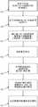
图2示出了根据本公开的示例实施方式的用于生成并发送通信信号的示例性(简化)发送路径。发送路径的实施方式可以被包括在通信设备(例如,UE或eNB)中。图3示出了根据本公开的示例实施方式的用于生成并发送通信信号的示例性(简化)流程图。注意,在301-304执行的步骤不是必要的,但是进行了描述仅用于更好地理解根据本公开的第一方面形成的子帧的发射。2 illustrates an exemplary (simplified) transmit path for generating and transmitting communication signals in accordance with an exemplary embodiment of the present disclosure. Embodiments of the transmit path may be included in a communication device (eg, UE or eNB). 3 shows an exemplary (simplified) flow diagram for generating and transmitting communication signals in accordance with an exemplary embodiment of the present disclosure. Note that the steps performed at 301-304 are not essential, but are described only for better understanding of the transmission of subframes formed in accordance with the first aspect of the present disclosure.
将来自更高层的用户和/或控制数据以数据块的形式提供给编码器201,并且编码器201对数据块进行编码(301)。将经编码的数据块提供给调制器202,并且调制器202对经编码的数据进行调制(302)以获得对应于经编码的数据的多个调制符号的时间序列。接下来,DFT扩频单元203使用离散傅里叶变换(DFT)扩频处理,对对应于经编码的数据的多个调制符号的时间序列进行变换预编码(303)。参考符号生成单元204提供的调制符号和参考符号(如果有的话)随后在子载波映射单元205中被映射(304)到给定子帧的子载波的资源要素(RE)。User and/or control data from higher layers is provided to the
在一种示例实施方式中,调制符号和参考符号(如果有的话)到形成子帧的时间和频率资源网格的映射(304)产生图1的子帧结构。该子帧可以在频域中具有预定数目
在子载波映射单元205中进行映射之后,在IFFT单元206中对子帧的个别OFDM/SC-FDMA符号进行逆快速傅里叶变换(IFFT)(305),以获得子帧的OFDM/SC-FDMA符号的时域表示,以供通信设备的RF电路207进行发送(306)。After mapping in the
注意,代替FFT/IFFT,在块203/303和206/305中可以使用DFT/逆离散傅里叶变换(IDFT)或离散余弦变换(DCT)/逆离散余弦变换(IDCT)。另外,图2和图3中的简化发送路径和流程图没有考虑经由不同的天线端口发送通信信道的多输入多输出(MIMO)。在使用MIMO的情况下,图2和图3的发送路径和流程图可以在以下方面进行扩展,即,可以将调制器202的调制符号分离(例如,复用)到(对应于不同的天线端口的)不同层中,并且对每层的经调制符号进行映射(304)、IFFT变换(305)、并经由不同的天线端口进行发送(306)。另外,还可以在将个别层的经调制的符号传递到子载波映射单元205之前,对所述个别层的经调制符号进行预编码。该层的预编码可以包括例如,空间复用、循环延迟分集(CDD)处理、空间-频率块编码(SFBC)等。显然,用于MIMO层的不同的并行处理路径均可以产生图1示出并在上文中讨论的子帧结构。Note that instead of FFT/IFFT, DFT/Inverse Discrete Fourier Transform (IDFT) or Discrete Cosine Transform (DCT)/Inverse Discrete Cosine Transform (IDCT) may be used in
假设基于LTE或LTE-A的系统中的示例性方案,IFFT尺寸NFFT相对于传统LTE FFT尺寸


图4示出了根据本公开的示例实施方式的用于接收对应于子帧的通信信号的示例性(简化)接收路径。接收路径的实施方式可以被包括在通信设备(例如,UE或eNB)中。图5示出了根据本公开的示例实施方式的用于接收对应于子帧的通信信号的示例性(简化)流程图。注意,在503-507执行的步骤不是必需的,但是进行了描述仅用于更好地理解对根据本公开的第一方面形成的子帧的接收。4 illustrates an exemplary (simplified) receive path for receiving a communication signal corresponding to a subframe in accordance with an exemplary embodiment of the present disclosure. Embodiments of the receive path may be included in a communication device (eg, UE or eNB). FIG. 5 shows an exemplary (simplified) flow diagram for receiving a communication signal corresponding to a subframe in accordance with an exemplary embodiment of the present disclosure. Note that the steps performed at 503-507 are not required, but are described only for a better understanding of the reception of subframes formed in accordance with the first aspect of the present disclosure.
根据本公开的第一方面,通信设备(例如,RAN中的网络元件,例如,位于车辆中的UE或者eNB)的RF电路401接收(501)通信信号。通信信号对应于类似于图1所示的子帧的时域OFDM/SC-FDMA符号。该子帧可以例如,携带指定用于V2X通信的物理信道的信息。将所接收的通信信号传递到FFT单元402,FFT单元402对所接收的通信信号应用尺寸为NFFT的FFT(502),从而获得子帧的OFDM/SC-FDMA符号。FFT单元402所使用的FFT尺寸可以为

另外,在子载波解映射单元403中对频域中的通信信号的不同的经FFT变换的部分进行解映射(503),以获得子帧的OFDM/SC-FDMA符号。如同前一实施方式,通过对通信信号应用FFT(502)并进行解映射(503)获得的子帧可以在频域中具有预定数目
注意,代替FFT/IFFT,可以在块402/502和405/506中使用DFT/IDFT或DCT/IDCT。另外,图4和图5中的简化发送路径和流程图没有考虑经由不同的天线端口发送通信信道的MIMO。在使用MIMO的情况下,可以在以下方面对图4和图5的接收路径和流程图进行扩展,即,可以经由不同的天线端口接收对应于各个MIMO层的不同通信信号。可以根据步骤502-504分别处理不同层的通信信号。在IFFT单元405中进行IFFT变换(506)之前,可能需要MIMO接收信号均衡和进一步的接收处理。另外,不同MIMO层的调制符号可以在取消解码处理之后结合(例如,解复用)到一个调制符号流中,然后可以对该调制符号流进行解调(506)和解码(507)。Note that instead of FFT/IFFT, DFT/IDFT or DCT/IDCT may be used in
注意,在传统的基于LTE的系统中(并且在本公开的大部分而不是所有实施方式中),发射机侧的IFFT尺寸等于接收机侧的FFT尺寸。Note that in conventional LTE-based systems (and in most but not all embodiments of this disclosure), the IFFT size on the transmitter side is equal to the FFT size on the receiver side.
接下来,结合具有增大的子载波间隔ΔfSC和减小的OFDM/SC-FDMA符号持续时间Tsymb的经修改的SL信号参数集来讨论第一方面的更详细的示例性实施方式。用于携带LTE物理信道的经修改的子帧结构相比传统的LTE系统具有更大的子载波间隔ΔfSC,其中,子载波间隔

将子载波间隔定义为ΔfSC=n·Δflegacy,其中,n是大于1的整数(例如,2的倍数),
--FFT/IFFT尺寸
-当系统BW=1.4MHz时,NFFT=64;- when system BW=1.4MHz,NFFT =64;
-当系统BW=3MHz时,NFFT=128;- when system BW=3MHz,NFFT =128;
-当系统BW=5MHz时,NFFT=256;- when system BW=5MHz,NFFT =256;
-当系统BW=10MHz时,NFFT=512;- when system BW=10MHz,NFFT =512;
-当系统BW=15MHz时,NFFT=768或1024;- when system BW=15MHz,NFFT =768 or 1024;
-当系统BW=20MHz时,NFFT=1024。- When the system BW=20MHz,NFFT =1024.
--与传统LTE相比,采样时间TS保持不变,因为(对于上述不同的传统系统BW):-- Compared to legacy LTE, the sampling time TS remains the same because (for the different legacy systems BW mentioned above):

--与传统LTE符号
-对于子帧的两个时隙中每个时隙的第一OFDM/SC-FDMA符号的正常CP(CP0),- for the normal CP (CP0) of the first OFDM/SC-FDMA symbol of each of the two slots of the subframe,

-对于子帧的两个时隙中每个时隙的第二至第六OFDM/SC-FDMA符号的正常CP(CP1),- for the normal CP (CP1) of the second to sixth OFDM/SC-FDMA symbols of each of the two slots of the subframe,

-对于子帧的OFDM/SD-FDMA符号的扩展CP(ECP),- Extended CP (ECP) for OFDM/SD-FDMA symbols of subframes,

--子帧持续时间TSF减少了因子n:
下表概略示出了针对不同系统BW(“带宽”)和不同子载波间隔(ΔfSC)的上述各种参数。注意,参数“nPRB”是指可用于系统BW(“带宽”)和不同子载波间隔(ΔfSC)的给定设置的PRB:The following table outlines the various parameters described above for different system BWs ("bandwidths") and different subcarrier spacings (ΔfSC ). Note that the parameter "nPRB" refers to the PRBs available for a given setting of system BW ("bandwidth") and different subcarrier spacing (ΔfSC ):


表1Table 1
本公开的第二方面涉及增强型解调参考信号(DMRS)图案。在本公开的一些实施方式中建议的DMRS图案可以使参考信号(RS)之间的时间间隔减小,从而有助于针对不同数据和控制SL物理信道(例如,PSSCH、PSCCH、PSDCH等)的更精确的CFO估计和/或信道估计。当用在(传统或非传统LTE)UL和DL物理信道(例如,PDSCH、PDCCH、PDDCH、PUSCH、PUCCH等)上时,对于本公开中建议的DMRS图案的改进还可以有助于对这些信道的更精确的CFO估计和/或信道估计。根据第二方面,可以增大每个子帧携带DMRS的OFDM/SC-FDMA符号的数目(例如,每个子帧有4个DMRS)和/或优化子帧中携带DMRS的相邻OFDM/SC-FDMA符号之间的距离,来提高CFO估计和/或信道估计精确度。例如,DMRS符号之间的时间间隔减小导致可以在UE处被估计从而可以在UE处被处理的最大CFO增加。对DMRS符号的数目以及它们的位置的修改还可以影响信道估计精度,因为它们可以使能更好的信道内插滤波精度。A second aspect of the present disclosure relates to enhanced demodulation reference signal (DMRS) patterns. The proposed DMRS pattern in some embodiments of the present disclosure may reduce the time interval between reference signals (RS), thereby facilitating the communication for different data and control SL physical channels (eg, PSSCH, PSCCH, PSDCH, etc.). More accurate CFO estimation and/or channel estimation. When used on (legacy or non-legacy LTE) UL and DL physical channels (eg, PDSCH, PDCCH, PDDCH, PUSCH, PUCCH, etc.), improvements to the DMRS patterns suggested in this disclosure may also help with these channels more accurate CFO estimates and/or channel estimates. According to the second aspect, the number of OFDM/SC-FDMA symbols carrying DMRS per subframe can be increased (eg, 4 DMRS per subframe) and/or the adjacent OFDM/SC-FDMA carrying DMRS in a subframe can be optimized distance between symbols to improve CFO estimation and/or channel estimation accuracy. For example, a reduction in the time interval between DMRS symbols results in an increase in the maximum CFO that can be estimated at the UE and thus processed at the UE. Modifications to the number of DMRS symbols and their positions can also affect channel estimation accuracy, as they can enable better channel interpolation filtering accuracy.
根据传统LTE设计,用于基于OFDM/SC-FDMA的系统的DMRS可以具有频率连续发射图案,并且可以占用所分配的符号中的PRB对中的所有RE(例如,一个符号中12个连续RE)。但是,将从下面的内容变得显而易见的是,也可以为非频率连续发射图案设计DMRS,从而使得它们不占用OFDM/SC-FDMA符号的PRB对中的所有RE。在后一种情况中,携带DMRS符号的RE可以具有周期性图案(例如,OFDM/SC-FDMA符号的PRB对中的每第m个RE携带DMRS符号)。注意,这里使用的术语“DMRS符号”是指携带部分DMRS RE的时域OFDM/SC-FDMA符号。According to legacy LTE designs, DMRS for OFDM/SC-FDMA based systems may have a frequency contiguous transmission pattern and may occupy all REs in a PRB pair in an allocated symbol (eg, 12 consecutive REs in one symbol) . However, it will become apparent from the following that DMRSs can also be designed for non-frequency continuous transmission patterns such that they do not occupy all REs in a PRB pair of an OFDM/SC-FDMA symbol. In the latter case, REs carrying DMRS symbols may have a periodic pattern (eg, every mth RE in a PRB pair of OFDM/SC-FDMA symbols carries a DMRS symbol). Note that the term "DMRS symbol" as used herein refers to a time-domain OFDM/SC-FDMA symbol that carries a partial DMRS RE.
可选地,可以通过在无线电接口上使用第一方面(例如,图1所示)的子帧结构并且在该子帧结构中采用根据第二方面的DMRS图案,来结合本公开的第一方面和第二方面。另外,应该注意的是,第二方面和其实施方式适用于V2X通信环境,但是不限于此。Optionally, the first aspect of the present disclosure may be combined by using the subframe structure of the first aspect (eg, shown in Figure 1 ) on the radio interface and employing a DMRS pattern according to the second aspect in the subframe structure and the second aspect. Additionally, it should be noted that the second aspect and its embodiments are applicable to a V2X communication environment, but are not limited thereto.
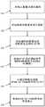
下面参考图2和图6讨论第二方面的示例性实施方式。图6示出了根据本公开的示例实施方式的用于将DMRS映射到子帧并发送子帧的示例性(简化)流程图。注意,在图6的301-301和305执行的步骤对应于以上参考图3描述的步骤,并且不是第二方面的实施方式所必需的。另外,类似于以上结合图3的说明,可以在第二方面中使用MIMO机制。另外需要注意的是,根据第一方面(例如,图1)的子帧的使用在该示例实施方式中也是可能的但不是强制的。该实施方式还参考传统的LTE子帧结构。Exemplary embodiments of the second aspect are discussed below with reference to FIGS. 2 and 6 . 6 shows an exemplary (simplified) flow diagram for mapping DMRS to subframes and transmitting the subframes in accordance with an exemplary embodiment of the present disclosure. Note that the steps performed at 301-301 and 305 of Fig. 6 correspond to the steps described above with reference to Fig. 3 and are not required for the implementation of the second aspect. Additionally, similar to the description above in connection with FIG. 3, a MIMO mechanism may be used in the second aspect. It should also be noted that the use of subframes according to the first aspect (eg Figure 1 ) is also possible but not mandatory in this example embodiment. This embodiment also refers to the conventional LTE subframe structure.
与图3的实施方式不同,对子载波映射单元205执行的将经FFT处理的调制符号和DMRS映射到子帧的处理(601)进行修改,使得多个DMRS被映射到子帧中的至少两个(例如,两个或四个)OFDM/SC-FDMA符号。该子帧可以在频域中具有预定数目
可选地,在时域中,子帧被划分为两个时隙。如果有两个DMRS被映射到子帧,则将每个DMRS映射到子帧的不同时隙。如果有四个DMRS被映射到子帧,则将两个DMRS映射到子帧中的第一时隙中的OFDM/SC-FDMA符号,并将其余两个DMRS映射到子帧的第二时隙中的OFDM/SC-FDMA符号。Optionally, in the time domain, the subframe is divided into two slots. If two DMRSs are mapped to a subframe, each DMRS is mapped to a different slot of the subframe. If there are four DMRSs mapped to a subframe, map two DMRSs to OFDM/SC-FDMA symbols in the first slot in the subframe and map the remaining two DMRSs to the second slot of the subframe OFDM/SC-FDMA symbols in .
图1所示的子帧结构中示例性地示出了时隙结构,其中,可以认为第一半(即,7个)OFDM/SC-FDMA符号形成了子帧的第一时隙,第二半(即,7个)OFDM/SC-FDMA符号形成了子帧的第二时隙。例如,如图1所示,可以认为子帧的个别OFDM/SC-FDMA符号在时域中由索引0至Nsymb-1索引,以在下面的公开中更容易地引用这些OFDM/SC-FDMA符号。The time slot structure is exemplarily shown in the subframe structure shown in FIG. 1, wherein the first half (ie, 7) OFDM/SC-FDMA symbols can be considered to form the first time slot of the subframe, and the second Half (ie, 7) OFDM/SC-FDMA symbols form the second slot of the subframe. For example, as shown in Figure 1, the individual OFDM/SC-FDMA symbols of a subframe can be considered to be indexed in the time domain by
每个子帧的DMRS的数目和/或DMRS将被映射到的OFDM/SC-FDMA符号的数目可以由例如,网络(例如,eNB)使用RRC信令(使用对应的RRC消息)配置。The number of DMRSs per subframe and/or the number of OFDM/SC-FDMA symbols to which the DMRSs are to be mapped may be configured by, for example, the network (eg, eNB) using RRC signaling (using corresponding RRC messages).
在第二方面的一种示例性实施方式中,假设子帧具有索引为0至13的Nsymb=14个OFDM/SC-FDMA符号,每个OFDM/SC-FDMA符号可以具有正常循环前缀,并且DMRS由UE在以下符号中发送:In an exemplary embodiment of the second aspect, assuming that the subframe hasNsymb = 14 OFDM/SC-FDMA symbols with indices from 0 to 13, each OFDM/SC-FDMA symbol may have a normal cyclic prefix, and The DMRS is sent by the UE in the following symbols:
-具有索引3和10的OFDM/SC-FDMA符号,或- OFDM/SC-FDMA symbols with
-具有索引5和8的OFDM/SC-FDMA符号,或- OFDM/SC-FDMA symbols with
-具有索引2、6、7、和11的OFDM/SC-FDMA符号,或- OFDM/SC-FDMA symbols with
-具有索引3、6、7、和10的OFDM/SC-FDMA符号,或- OFDM/SC-FDMA symbols with
-具有索引4、6、7、和9的OFDM/SC-FDMA符号,或- OFDM/SC-FDMA symbols with
-具有索引2、3、10、和11的OFDM/SC-FDMA符号,或- OFDM/SC-FDMA symbols with
-具有索引2、4、9、和11的OFDM/SC-FDMA符号。- OFDM/SC-FDMA symbols with
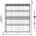
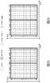
图7至图12中示出了DMRS到不同OFDM/SC-FDMA符号的上述示例性映射。图7至图13示出了用于SL的子帧的示例性结构,并且为了简单将对应的物理信道称为“PSXCH”(例如,PSSCH、PSCCH等)。The above-described exemplary mappings of DMRS to different OFDM/SC-FDMA symbols are shown in Figures 7-12. 7 to 13 illustrate exemplary structures of subframes for SL, and the corresponding physical channel is referred to as "PSXCH" (eg, PSSCH, PSCCH, etc.) for simplicity.
DMRS 3/8映射具有与传统LTE DMRS(DMRS 3/10)相同的开销。但是,DMRS间距离减小,这使得CFO估计和信道估计对于高多普勒衰落和频率偏移的鲁棒性增加。
在DMRS 2/6/7/11映射、DMRS 4/6/7/9映射、以及DMRS 2/4/9/11映射中,每个子帧有均匀分布的四个DMRS符号。OFDM/SC-FDMA符号6和7上的DMRS可以用来增加CFO估计的可靠性。In
DMRS 3/6/7/10映射可以是有利的,因为这四个DMRS符号中的两个DMRS符号具有与传统DMRS相同的位置,从而潜在地使能动态DMRS图案选择机制(例如,针对一些UE使用传统图案,针对其他UE使用增强型DMRS图案)。
在DMRS 2/3/10/11映射中,每个子帧也有四个DMRS符号。两个DMRS符号具有与传统DMRS相同的位置。OFDM/SC-FDMA符号2和3上的DMRS和OFDM/SC-FDMA符号10和11上的DMRS可以用来增加CFO估计的可靠性。In
在第二方面的另一示例性实施方式中,假设子帧具有索引为0至11的Nsymb=12个OFDM/SC-FDMA符号,每个OFDM/SC-FDMA符号可以具有扩展循环前缀,并且DMRS由UE在以下符号中发送:In another exemplary embodiment of the second aspect, assuming that the subframe has Nsymb = 12 OFDM/SC-FDMA symbols indexed from 0 to 11, each OFDM/SC-FDMA symbol may have an extended cyclic prefix, and The DMRS is sent by the UE in the following symbols:
-具有索引2和8的OFDM/SC-FDMA符号(DMRS 2/8),或- OFDM/SC-FDMA symbols with
-具有索引3和7的OFDM/SC-FDMA符号(DMRS 3/7),或- OFDM/SC-FDMA symbols with
-具有索引4和7的OFDM/SC-FDMA符号(DMRS 4/7),或- OFDM/SC-FDMA symbols with
-具有索引2、5、6、和9的OFDM/SC-FDMA符号(DMRS2/5/6/9),或- OFDM/SC-FDMA symbols with
-具有索引3、5、6、和8的OFDM/SC-FDMA符号(DMRS3/5/6/8),或- OFDM/SC-FDMA symbols with
-具有索引2、3、8、和9的OFDM/SC-FDMA符号(DMRS2/3/8/9)。- OFDM/SC-FDMA symbols with
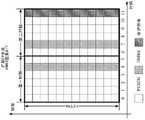
图14至图19示出了DMRS到不同OFDM/SC-FDMA符号的上述示例性映射。如同图7至图13一样,图14至图19示出了用于SL的子帧的示例性结构,并且为了简单将对应的物理信道称为“PSXCH”。14 to 19 illustrate the above-described exemplary mapping of DMRS to different OFDM/SC-FDMA symbols. Like FIGS. 7 to 13 , FIGS. 14 to 19 illustrate exemplary structures of subframes for SL, and the corresponding physical channel is referred to as 'PSXCH' for simplicity.
DMRS 3/7映射和DMRS 4/7映射具有与传统DMRS(DMRS 2/8)相同的开销,同时DMRS间距离减小了。这有助于增加信道和CFO估计对于高多普勒衰减的鲁棒性。
DMRS 2/5/6/9映射和DMRS 3/5/6/8映射分别为每个子帧提供均匀分布的四个DMRS符号。映射到OFDM/SC-FDMA符号5和6的DMRS可以用来增加CFO估计的可靠性。
DMRS 2/3/8/9映射具有以下优点,即,两个DMRS具有与传统LTE子帧中相同的位置。映射到OFDM/SC-FDMA符号2和3的DMRS和映射到OFDM/SC-FDMA符号8和9的DMRS可用来增加CFO估计的可靠性。
以上讨论的第二方面的扩展涉及用于DMRS的新发射机制,其中,DMRS不占用相应OFDM/SC-FDMA符号的所有RE。在第二方面的扩展中,进行测量以使子帧的每个DMRS具有占用携带该DMRS的相应OFDM/SC-FDMA符号的预定周期性图案的RE的发射图案(即,仅占用相应OFDM/SC-FDMA符号的可用RE的子集,例如,每第m个RE,m∈{2,3,4,…,8})。An extension of the second aspect discussed above involves a new transmission mechanism for DMRS, where DMRS does not occupy all REs of the corresponding OFDM/SC-FDMA symbol. In an extension of the second aspect, measurements are made such that each DMRS of a subframe has a transmission pattern that occupies a predetermined periodic pattern of REs carrying the corresponding OFDM/SC-FDMA symbols of the DMRS (ie, only occupies the corresponding OFDM/SC - Subset of available REs for FDMA symbols, eg every mth RE, m∈{2,3,4,...,8}).
下面参考图20和图21讨论用于这种稀疏DMRS发射的两种示例性实施方式,但是第二方面的扩展不限于这两种实施方式。Two exemplary embodiments for such sparse DMRS transmission are discussed below with reference to Figures 20 and 21, but the extension of the second aspect is not limited to these two embodiments.
下面参考图2和图20讨论第二方面的扩展的示例性第一实施方式。图20示出了根据用于稀疏DMRS发射的两种实施方式中的第一种实施方式的用于将DMRS映射到子帧并发送子帧的示例性(简化)流程图。注意,在图20中的301-303和305执行的步骤对应于以上参考图3描述的步骤,并且对于第二方面的扩展的实施方式不是必需的。另外,类似于结合图3的上述说明,可以在第二方面中使用MIMO机制。进一步地,注意,根据第一方面(例如,图1)的子帧的使用在本示例实施方式中也是可以的但不是强制的。该实施方式还参考传统的LTE子帧结构。An exemplary first embodiment of an extension of the second aspect is discussed below with reference to FIGS. 2 and 20 . Figure 20 shows an exemplary (simplified) flow diagram for mapping DMRS to subframes and transmitting subframes according to the first of two implementations for sparse DMRS transmission. Note that the steps performed at 301-303 and 305 in Figure 20 correspond to the steps described above with reference to Figure 3, and are not necessary for the extended implementation of the second aspect. In addition, similar to the above description in connection with FIG. 3, a MIMO mechanism may be used in the second aspect. Further, note that the use of subframes according to the first aspect (eg, Figure 1 ) is also possible but not mandatory in this example embodiment. This embodiment also refers to the conventional LTE subframe structure.
除了以下不同以外,参考图20描述的实施方式对应于图6的实施方式。在该示例性实施方式中,DMRS被设计用于非频率连续发射图案,因而它们不占用OFDM/SC-FDMA符号(的PRB对)中的所有RE。替代地,携带DMRS符号的RE可以具有周期性图案(例如,OFDM/SC-FDMA符号的PRB对中的每第m个RE携带DMRS符号)。当根据给定的DMRS图案(例如,如结合图7至图19讨论的)将DMRS映射(2001)到相应OFDM/SC-FDMA符号的相应RE(DMRS符号)时,子载波映射单元205确保将DMRS的相应DMRS符号仅映射到相应OFDM/SC-FDMA符号中的RE的子集,以使DMRS符号形成周期性图案。在发射步骤2002中,RF电路207针对OFDM/SC-FDMA符号的DMRS符号已经被映射到的RE的发射使用非零功率,并且零功率被用于OFDM/SC-FDMA符号的没有DMRS符号被映射到的RE的发射。The embodiment described with reference to FIG. 20 corresponds to the embodiment of FIG. 6 except for the following differences. In this exemplary embodiment, the DMRSs are designed for non-frequency contiguous transmission patterns, so they do not occupy all REs in (the PRB pairs of) OFDM/SC-FDMA symbols. Alternatively, REs carrying DMRS symbols may have a periodic pattern (eg, every mth RE in a PRB pair of an OFDM/SC-FDMA symbol carries a DMRS symbol). When mapping (2001) the DMRS to the corresponding RE (DMRS symbol) of the corresponding OFDM/SC-FDMA symbol according to a given DMRS pattern (eg, as discussed in connection with Figures 7 to 19), the
子帧的每个OFDM/SC-FDMA符号可以具有映射到子帧的相应


用于映射(2001)的周期性图案可以由例如,网络(例如,eNB)使用RRC信令配置。例如,用于配置周期性图案的RRC消息可以指示上述参数k和m。The periodic pattern used for mapping (2001) may be configured by, eg, the network (eg, eNB) using RRC signaling. For example, the RRC message for configuring the periodic pattern may indicate the above-mentioned parameters k and m.
下面参考图2和图21讨论第二方面的扩展的示例性的第二实施方式。图21示出了根据用于稀疏DMRS发射的两种实施方式中的第二实施方式的用于将DMRS映射到子帧并发送子帧的示例性(简化)流程图。注意,在图20中的301-303和305执行的步骤对应于以上参考图3描述的步骤,并且对于第二方面的扩展的实施方式不是必需的。另外,类似于以上结合图3的说明,也可以在第二方面中使用MIMO机制。另外,注意,根据第一方面(例如,图1)的子帧的使用在该示例实施方式中是可以的但不是强制性的。该实施方式也参考传统的LTE子帧结构。An exemplary second embodiment of the extension of the second aspect is discussed below with reference to FIGS. 2 and 21 . Figure 21 shows an exemplary (simplified) flow diagram for mapping DMRS to subframes and transmitting subframes according to the second of two implementations for sparse DMRS transmission. Note that the steps performed at 301-303 and 305 in Figure 20 correspond to the steps described above with reference to Figure 3, and are not necessary for the extended implementation of the second aspect. In addition, similar to the description above in connection with FIG. 3, a MIMO mechanism may also be used in the second aspect. Also, note that the use of subframes according to the first aspect (eg, Figure 1 ) is possible but not mandatory in this example embodiment. This embodiment also refers to the conventional LTE subframe structure.
在经扩展的第二方面的第二实施方式中,每个DMRS(仍然)具有占用携带DMRS的相应OFDM/SC-FDMA符号的所有RE的频率连续发射图案。但是,在发射之前,对一些RE穿孔,以使得仅OFDM/SC-FDMA符号中的RE的子集携带DMRS。例如,可以这样穿孔,即对OFDM/SC-FDMA符号的每第m个RE进行穿孔。In a second implementation of the extended second aspect, each DMRS (still) has a frequency-continuous transmission pattern occupying all REs of the corresponding OFDM/SC-FDMA symbol carrying the DMRS. However, before transmission, some REs are punctured so that only a subset of REs in an OFDM/SC-FDMA symbol carry DMRS. For example, puncturing may be performed such that every mth RE of an OFDM/SC-FDMA symbol is punctured.
除了以下不同以外,参考图21描述的实施方式对应于图6的实施方式。在根据给定的DMRS图案将DMRS映射(601)到该子集中的相应OFDM/SC-FDMA符号的(所有)RE(DMRS符号)之后(例如,如以上结合图7至图19所讨论的),将子帧结构传递给穿孔单元(图2中未示出)。穿孔单元使用周期性穿孔图案对DMRS被映射到的OFDM/SC-FDMA符号的RE的子集进行穿孔(2101)。随后将在其OFDM/SC-FDMA符号中具有穿孔DMRS的子帧从穿孔单元传递到RF电路207,类似于图21的实施方式,该RF电路使用非零功率来发送(2002)OFDM/SC-FDMA符号的DMRS已经被映射到的非穿孔RE(DMRS符号),并使用零功率来发送OFDM/SC-FDMA符号的DMRS已经被映射到的穿孔RE。The embodiment described with reference to FIG. 21 corresponds to the embodiment of FIG. 6 except for the following differences. After mapping (601) the DMRS to (all) REs (DMRS symbols) of the corresponding OFDM/SC-FDMA symbols in the subset according to the given DMRS pattern (eg, as discussed above in connection with Figures 7-19) , the subframe structure is passed to the puncturing unit (not shown in FIG. 2 ). The puncturing unit punctures the subset of REs of the OFDM/SC-FDMA symbols to which the DMRS is mapped using a periodic puncturing pattern (2101). Subframes with punctured DMRS in their OFDM/SC-FDMA symbols are then passed from the punctured unit to
例如,在RE具有除j(x)=k+m·x以外的索引j的情况下,可以通过对OFDM/SC-FDMA符号的DMRS已经被映射到的所有RE进行穿孔来获取穿孔RE的周期性图案,其中,
将用于映射(2001)的周期性穿孔图案可以由例如,网络(例如,eNB)使用RRC信令配置。例如,用于配置穿孔图案的RRC消息可以指示上述参数k和m。The periodic puncturing pattern to be used for mapping (2001) may be configured by, eg, the network (eg, eNB) using RRC signaling. For example, the RRC message for configuring the puncturing pattern may indicate the above parameters k and m.
注意,根据结合图20和图21描述的第二方面的上述扩展,在使用RF电路207发送作为结果的时域通信信号之前,仍然可以对包括DMRS的子帧进行尺寸为NFFT的IFFT。由于携带DMRS的OFDM/SC-FDMA符号的RE中的周期性图案并且由于应用IFFT(305),时域通信信号包括m(2,…)个连续版本(子部分),即相应的经IFFT变换的DMRS在时域中的重复。这可以在例如,接收机侧用来改进对载波频率偏移(CFO)的估计。Note that in accordance with the above extensions of the second aspect described in connection with Figures 20 and 21, an IFFT of size NFFT may still be performed on subframes comprising DMRS prior to transmitting the resulting time domain communication signal using
根据本公开的经扩展的第二方面的另一实施方式涉及从用户设备(UE)接收指定用于V2X通信的物理信道的子帧中的通信信号的通信设备,下面将结合图4、图22、和图23描述该通信设备。图22示出了在通信设备处接收根据以上有关图20和图21的说明发送的通信信号并确定CFO的示例性流程图。图23示例性地示出了发送具有以周期性图案提供的DMRS符号的OFDM/SC-FDMA符号的效果。注意,在图22的503-507执行的步骤对应于以上参考图5描述的步骤,并且对于第二方面的实施方式不是必需的。类似于以上结合图5的说明,也可以在第二方面中使用MIMO机制。进一步地,注意,根据第一方面(例如,图1)的子帧的使用在该示例实施方式中也是可以的但不是强制的。该实施方式也参考传统的LTE子帧结构。Another embodiment according to the extended second aspect of the present disclosure relates to a communication device receiving a communication signal from a user equipment (UE) in a subframe of a physical channel designated for V2X communication, which will be described below in conjunction with FIG. 4 and FIG. 22 . , and FIG. 23 describe the communication device. 22 illustrates an exemplary flow diagram for receiving, at a communication device, communication signals sent in accordance with the descriptions above with respect to FIGS. 20 and 21 and determining CFO. FIG. 23 exemplarily shows the effect of transmitting OFDM/SC-FDMA symbols with DMRS symbols provided in a periodic pattern. Note that the steps performed at 503-507 of Fig. 22 correspond to the steps described above with reference to Fig. 5, and are not required for implementation of the second aspect. Similar to the description above in connection with Figure 5, a MIMO mechanism may also be used in the second aspect. Further, note that the use of subframes according to the first aspect (eg, Figure 1 ) is also possible but not mandatory in this example embodiment. This embodiment also refers to the conventional LTE subframe structure.
通信节点可以使用其RX电路401来从发射机侧(例如,UE)接收(501a)根据以上有关图20和图21的说明发送的通信信号。出于实施第二方面的目的,可选地,在步骤2201,通信设备的FFT单元402向通信信号的对应于子帧的没有携带DMRS的OFDM/SC-FDMA符号的部分应用尺寸为NFFT的FFT。相应地,对于所接收的通信信号的这些部分的处理类似于结合图5的步骤502描述的处理。The communication node may use its
如图23所示,由于映射到子帧的一个或多个DMRS具有横跨频率的子载波的周期性图案(DMRS符号被包括在OFDM/SC-FDMA符号的相应DMRS被映射到的每第m个RE(例如,如图23所示的每第2个RE)),通信信号具有在尺寸上对应于尺寸为NFFT/m的FFT变换的m(例如,2)个相同的信号分量(子部分)。通信设备的FFT单元402对所接收的对应于不同DMRS的通信信号应用尺寸为NFFT_RX=NFFT/m的FFT(2202),其中,NFFT是发射机侧用来生成该通信信号的IFFT的尺寸。参数m∈{2,3,4,…}。As shown in FIG. 23 , since one or more DMRSs mapped to a subframe have a periodic pattern of subcarriers across frequencies (a DMRS symbol is included in every mth to which a corresponding DMRS of an OFDM/SC-FDMA symbol is mapped) REs (eg, every 2nd RE as shown in FIG. 23 ), the communication signal has m (eg , 2) identical signal components (sub- part). The
向时域的所接收的通信信号中对应于一个DMRS的m个连续子部分的各个子部分应用尺寸为NFFT_RX的FFT,以得出针对时域中的一个DMRS的m个连续子部分的每个子部分的、对应于子帧在频域中的相应资源要素(RE)的m组DMRS符号。如图23的右手侧所示,由于使用尺寸为NFFT_RX=NFFT/m的FFT,通信节点处每个OFDM/SC-FDMA符号的“重构”RE的数目有效减少了因子m。换言之,接收机侧的子载波间隔有效增加了因子m。另外,通信节点还可以包括CFO确定单元(图4中未示出),该CFO确定单元用于基于针对相应的一个DMRS获取的m组DMRS符号来估计(2203)接收信号载波频率偏移(CFO)。Apply an FFT of size NFFT_RX to each of the m contiguous sub-portions of a DMRS in the received communication signal in the time domain to obtain each of the m contiguous sub-portions of a DMRS in the time domain. m groups of DMRS symbols of the sub-portions corresponding to respective resource elements (REs) of the subframe in the frequency domain. As shown on the right hand side of Figure 23, the number of "reconstructed" REs per OFDM/SC-FDMA symbol at the communication node is effectively reduced by a factor m due to the use of an FFT of sizeNFFT_RX =NFFT /m. In other words, the subcarrier spacing at the receiver side is effectively increased by a factor m. In addition, the communication node may further include a CFO determination unit (not shown in FIG. 4 ) for estimating ( 2203 ) a received signal carrier frequency offset (CFO) based on m groups of DMRS symbols acquired for a corresponding one DMRS ).
例如,在一个示例中,CFO确定单元可以通过以下处理来估计接收信号CFO:确定所接收的通信信号的m个连续子部分之间的相位偏移,然后基于所确定的相位偏移来估计接收信号CFO。例如,为了估计CFO,UE可以对DMRS RE使用最小平方信道估计。可以在相位偏移由CFO导致并且在不存在相应偏移的情况下信道为静态的假设下,估计对应于给定的信道频率位置(RE)和不同符号的不同信道估计之间的相位偏移。可以通过将在第一符号上获得的信道估计与在另一符号上获得的共轭的信道估计相乘并且计算所得到的乘积的相位来完成该估计。另外,可以应用对应于不同RE的乘积估计的平均来提高精度。For example, in one example, the CFO determination unit may estimate the received signal CFO by determining the phase offset between m consecutive sub-portions of the received communication signal, and then estimating the received signal based on the determined phase offset Signal CFO. For example, to estimate CFO, the UE may use least squares channel estimation for DMRS REs. The phase offset between different channel estimates corresponding to a given channel frequency location (RE) and different symbols can be estimated under the assumption that the phase offset is caused by the CFO and that the channel is static in the absence of a corresponding offset . This estimation can be done by multiplying the channel estimate obtained on the first symbol with the conjugated channel estimate obtained on the other symbol and calculating the phase of the resulting product. Additionally, averaging of product estimates corresponding to different REs can be applied to improve accuracy.
注意,也可以在没有携带DMRS的其他OFDM/SC-FDMA符号(例如,携带用户数据或控制信息的OFDM/SC-FDMA符号)上,利用在子帧的OFDM/SC-FDMA符号中对RE进行周期性打孔或映射的方法。这将有效地增大子载波间隔(类似于结合上述第一方面讨论的子帧结构的改变后的参数集)。UE可以允许发射路径中的IFFT单元206使用更小的IFFT尺寸NFFT(例如,FFT尺寸可以减小因子2,即,NFFT/2),从而将时域中的OFDM/SC-FDMA符号持续时间缩短相同因子。注意,这可以通过在发射机侧进行IFFT之前定义子帧结构的新的子载波映射(映射图案)或者穿孔图案,来形成图1所示的同一物理信道结构。Note that it is also possible to perform REs in OFDM/SC-FDMA symbols of subframes on other OFDM/SC-FDMA symbols that do not carry DMRS (eg, OFDM/SC-FDMA symbols carrying user data or control information). A method for periodic punching or mapping. This will effectively increase the subcarrier spacing (similar to the changed parameter set of the subframe structure discussed in connection with the first aspect above). The UE may allow the
另外,应该注意的是,以上结合图20至图23讨论的经扩展的第二方面还可以用于一些传统的LTE DMRS机制。Additionally, it should be noted that the extended second aspect discussed above in connection with Figures 20-23 can also be used for some conventional LTE DMRS mechanisms.
另外,当DMRS以周期性图案仅占用子帧的相应OFDM/SC-FDMA符号中的RE的子集时,可以允许利用不同的周期性非重叠映射或穿孔图案来配置不同的UE,从而使得不同UE可以同时在子帧的相同OFDM/SC-FDMA符号但是不同RE上发送DMRS。这在不同UE具有不同图案的干扰受限环境中是有益的,并且由于DMRS RE上的干扰量减少,可以提高信道估计精度。In addition, when the DMRS occupies only a subset of REs in the corresponding OFDM/SC-FDMA symbols of the subframe in a periodic pattern, it may allow different UEs to be configured with different periodic non-overlapping mapping or puncturing patterns such that different The UE may simultaneously transmit DMRS on the same OFDM/SC-FDMA symbols of the subframe but on different REs. This is beneficial in interference-limited environments where different UEs have different patterns, and can improve channel estimation accuracy due to the reduced amount of interference on DMRS REs.
不同的候选DMPRS符号映射/穿孔图案中的一个特定图案的使用例如,对于所有UE可以是固定的或者可以由无线电接入网(例如,eNB)配置。另外,DMPRS符号映射/穿孔图案的配置可以与特定DMRS图案(即,指示子帧中的DMRS的数目和位置的图案)的配置一起进行。将由UE使用的一个或多个DMPRS符号映射/穿孔图案以及一个或多个DMRS图案的配置可以例如,在eNB在其无线电小区中广播的系统信息块(SIB)中或者经由RRC信令配置。The use of a particular one of the different candidate DMPRS symbol mapping/puncturing patterns may eg be fixed for all UEs or may be configured by the radio access network (eg eNB). In addition, the configuration of the DMPRS symbol mapping/puncturing pattern may be done together with the configuration of a specific DMRS pattern (ie, a pattern indicating the number and position of DMRS in a subframe). The configuration of the one or more DMPRS symbol mapping/puncturing patterns and the one or more DMRS patterns to be used by the UE may eg be configured in a system information block (SIB) broadcast by the eNB in its radio cell or via RRC signaling.
例如,假设OFDM/SC-FDMA符号中将携带DMRS符号的RE具有索引j(x)=k+m·x,
另一种可能是定义DMPRS符号映射/穿孔图案的候选集。图24示出了用于对OFDM/SC-FDMA符号中携带DMRS的RE进行穿孔的两种示例性穿孔图案(1,0)和(0,1)的使用。如这里所示出的,示例假设DMRS在被子载波映射单元205映射到子帧的子载波时覆盖OFDM/SC-FDMA符号的所有RE(参见图2,以及图6的步骤601)。在穿孔图案(1,0)的情况下,子载波的具有奇数索引的RE携带DMRS符号,同时子载波的具有偶数索引的RE携带DMRS符号并被穿孔(反之亦然)。在穿孔图案(0,1)的情况下,子载波的具有偶数索引的RE携带DMRS符号,同时子载波的具有奇数索引的RE携带DMRS符号并被穿孔(反之亦然)。一个比特足以从这两种穿孔图案中进行选择。注意,相同的概念可以用于定义映射图案。Another possibility is to define a candidate set of DMPRS symbol mapping/puncturing patterns. Figure 24 illustrates the use of two exemplary puncturing patterns (1,0) and (0,1) for puncturing REs carrying DMRS in OFDM/SC-FDMA symbols. As shown here, the example assumes that the DMRS covers all REs of the OFDM/SC-FDMA symbol when mapped to the subcarriers of the subframe by the subcarrier mapping unit 205 (see FIG. 2, and step 601 of FIG. 6). In the case of the puncturing pattern (1,0), REs with odd indices of subcarriers carry DMRS symbols, while REs with even indices of subcarriers carry DMRS symbols and are punctured (and vice versa). In the case of a puncturing pattern (0,1), REs with even indices of subcarriers carry DMRS symbols, while REs with odd indices of subcarriers carry DMRS symbols and are punctured (and vice versa). One bit is enough to select from these two perforation patterns. Note that the same concept can be used to define mapping patterns.
当然,DMPRS符号映射/穿孔图案的数目不一定被限制到2。例如,也可以使用4比特序列来表示四种不同的DMPRS符号映射/穿孔图案(即,(1,0,0,0)、(0,1,0,0)、(0,0,1,0)、(0,0,01)),其中,相邻DMRS符号之间的间隔为4比特。可选地,还可以使用4个比特来定义相邻DMRS符号之间的间隔为2或4比特的DMPRS符号映射/穿孔图案,即,(1,0,0,0)、(0,1,0,0)、(0,0,1,0)、(0,0,0,1)、(1,0,1,0)、以及(0,1,0,1)。Of course, the number of DMPRS symbol mapping/puncturing patterns is not necessarily limited to two. For example, four different DMPRS symbol mapping/puncturing patterns (ie, (1,0,0,0), (0,1,0,0), (0,0,1, 0), (0,0,01)), where the interval between adjacent DMRS symbols is 4 bits. Optionally, 4 bits may also be used to define a DMPRS symbol mapping/puncturing pattern with an interval of 2 or 4 bits between adjacent DMRS symbols, that is, (1,0,0,0), (0,1, 0,0), (0,0,1,0), (0,0,0,1), (1,0,1,0), and (0,1,0,1).
另一种可能可以是,不同UE基于UE标识符(例如,IMSI、RNTI等)的一些函数来选择候选DMRS符号映射/穿孔图案。例如,假设OFDM/SC-FDMA符号中将携带DMRS符号的RE具有索引j(X)=k+m·X,
注意,网络可以为SL(例如,用于V2V或V2P通信)、以及UL和/或DL(例如,用于V2I或V2N通信)配置不同的DMPRS符号映射/穿孔图案和/或DMRS图案。Note that the network may configure different DMPRS symbol mapping/puncturing patterns and/or DMRS patterns for SL (eg, for V2V or V2P communications), and UL and/or DL (eg, for V2I or V2N communications).
另外,这些原理还可以扩展到对本文中在前面讨论的子帧中的DMRS位置的增强。图25至图34示出了在假定符号具有正常CP的情况下子帧中不同的示例性DMRS图案,每个指示针对不同DMRS图案的子帧中的两种可能的不同DMRS映射/穿孔图案(“位置1”和“位置2”指示不同图案)。图35至图41示出了在假设符号具有扩展CP的情况下子帧中的不同的示例性DMRS图案,每个指示针对不同DMRS图案的子帧中的两种可能的不同DMRS映射/穿孔图案(“位置1”和“位置2”指示不同图案)。Additionally, these principles can also be extended to enhancements to the DMRS locations in the subframes discussed earlier herein. Figures 25 to 34 show different exemplary DMRS patterns in a subframe, each indicating two possible different DMRS mapping/puncturing patterns in a subframe for a different DMRS pattern ("
如本文中在前面提到的,可以通过在无线电接口上使用第一方面(例如,图1所示)的子帧结构并在该子帧结构中采用根据第二方面的DMRS图案来结合本公开的第一方面和第二方面,如结合图7至图19或图25至图34概略描述的。认为以下的示例配置是有利的(不需要限制其他组合的可行性):As mentioned earlier herein, the present disclosure may be incorporated by using the subframe structure of the first aspect (eg, shown in FIG. 1 ) on the radio interface and employing a DMRS pattern according to the second aspect in the subframe structure The first and second aspects of the , as generally described in conjunction with FIGS. 7 to 19 or 25 to 34 . The following example configurations are considered advantageous (without limiting the feasibility of other combinations):
例如,在OFDM/SC-FDMA符号具有正常CP的情况下:For example, in the case of OFDM/SC-FDMA symbols with normal CP:
-30kHz子载波间隔,间隔减小的2个DMRS(例如,DMRS图案5/8)-30kHz subcarrier spacing, 2 DMRS with reduced spacing (
-30kHz子载波间隔,4个DMRS(例如,DMRS图案2/5/8/11)-30kHz subcarrier spacing, 4 DMRS (e.g. DMRS
-60kHz子载波间隔,间隔减小的2个DMRS(例如,DMRS图案4/9)-60kHz subcarrier spacing, 2 DMRS with reduced spacing (
-60kHz子载波间隔,4个DMRS(例如,DMRS图案2/5/8/11)-60kHz subcarrier spacing, 4 DMRS (
例如,在OFDM/SC-FDMA符号具有扩展CP的情况下:For example, in the case of OFDM/SC-FDMA symbols with extended CP:
-30kHz子载波间隔,间隔减小的2个DMRS(例如,DMRS图案4/7)-30kHz subcarrier spacing, 2 DMRS with reduced spacing (
-30kHz子载波间隔,4个DMRS(例如,DMRS图案2/4/7/9)-30kHz subcarrier spacing, 4 DMRS (e.g. DMRS
-60kHz子载波间隔,间隔减小的2个DMRS(例如,DMRS图案3/7)-60kHz subcarrier spacing, 2 DMRS with reduced spacing (
-60kHz子载波间隔,4个DMRS(例如,DMRS图案2/4/7/9)-60kHz subcarrier spacing, 4 DMRS (
本公开的另一方面涉及用于V2X操作的基于TDM的资源分配。例如,对于V2X操作,eNB的调度器可以TDM方式向UE分配用于SL或UL发射的资源,例如,通过向UE分配子帧中或者子帧的一个时隙中的一个或多个OFDM/SC-FDMA符号的所有RE。Another aspect of the present disclosure relates to TDM-based resource allocation for V2X operations. For example, for V2X operation, the scheduler of the eNB may allocate resources for SL or UL transmission to the UE in a TDM manner, eg, by allocating to the UE one or more OFDM/SC in a subframe or in a slot of a subframe - All REs of FDMA symbols.
一般,可以在接收机侧进行FFT变换之前,通过将时域接收信号的对应于CP的相位偏移与给定OFDM/SC-FDMA符号末端的相同信号部分进行比较,使用基于CP的方法来估计CFO。这种方法的一个潜在问题在于,对于SL操作,多个信号可能被复用在相同的时间资源中(每个信号具有其自己的频率偏移)。因此,CFO估计可能会变得不太可靠并且不太精确。In general, CP-based methods can be used to estimate the phase offset of the received signal in the time domain corresponding to the CP by comparing the same signal portion at the end of a given OFDM/SC-FDMA symbol before the FFT transform at the receiver side CFO. One potential problem with this approach is that, for SL operation, multiple signals may be multiplexed in the same time resource (each with its own frequency offset). As a result, CFO estimates may become less reliable and less precise.
解决这个问题的一种可能的方法是针对V2X操作使用基于TDM的资源分配。例如,可以认为最小资源分配等于全系统BW(例如,针对10MHz BW和15kHz的载波间隔的50个PRB对)。One possible solution to this problem is to use TDM-based resource allocation for V2X operations. For example, the minimum resource allocation can be considered equal to the system-wide BW (eg, 50 PRB pairs for a 10 MHz BW and a carrier spacing of 15 kHz).
一般,可以在全系统中应用该方法,并且V2X操作中涉及的所有UE应该坚持全BW资源分配的相同原则。替代地,可以在个别链路上应用该方法。在后一种情况中,UE可以尝试获取有关资源分配的信息(例如,通过PSCCH解码),并且在检测到全系统BW(或宽带)资源分配被用于信号发送的情况下应用基于CP的CFO估计/补偿。In general, this method can be applied system-wide and all UEs involved in V2X operation should adhere to the same principle of full BW resource allocation. Alternatively, the method can be applied on individual links. In the latter case, the UE may attempt to obtain information about the resource allocation (eg, via PSCCH decoding) and apply CP-based CFO if it detects that the system-wide BW (or wideband) resource allocation is used for signaling Estimation/compensation.
该方案的一个可能的缺点在于,降低了调度器的资源分配的灵活性。但是,这个问题可以通过每个时隙的资源分配粒度(即,以每个时隙的粒度进行调度)来解决。例如,可以将最小资源分配粒度设置为1个时隙。另外或者可选地,还可以结合第一方面的子帧结构(例如,图1所示)使用该调度方法。随着子载波间隔的增大,频率中可用PRB的数目和时间中PRB持续时间均减少。因此,全BW资源分配是一种可行的选择。A possible disadvantage of this approach is that the flexibility of the scheduler's resource allocation is reduced. However, this problem can be solved by resource allocation granularity per slot (ie, scheduling at per slot granularity). For example, the minimum resource allocation granularity can be set to 1 slot. Additionally or alternatively, the scheduling method may also be used in combination with the subframe structure of the first aspect (eg, as shown in FIG. 1 ). As the subcarrier spacing increases, both the number of available PRBs in frequency and the PRB duration in time decrease. Therefore, full BW resource allocation is a viable option.
接下来,描述本公开的第三方面及其不同示例性实施方式。本公开的第三方面涉及对多普勒效应导致的CFO进行补偿的方案。一般,CFO可能在接收机侧用于下变频的本地振荡信号不与发射的接收信号中包含的载波信号同步时出现。CFO会受到发射机和接收机振荡器中的频率失配以及多普勒效应(尤其是,在发射机和接收机中的一者或两者在移动时)的影响。CFO会影响网络元件(即,UE和eNB)的DL、UL、以及SL发射。Next, a third aspect of the present disclosure and various exemplary embodiments thereof are described. A third aspect of the present disclosure relates to a scheme for compensating for CFO caused by the Doppler effect. In general, CFO may occur when the local oscillator signal used for downconversion at the receiver side is not synchronized with the carrier signal contained in the transmitted received signal. CFO can be affected by frequency mismatches in transmitter and receiver oscillators, as well as Doppler effects (especially when one or both of the transmitter and receiver are moving). CFO affects DL, UL, and SL transmissions of network elements (ie, UE and eNB).
CFO使得接收信号在频率上移位。对于基于OFDM/SC-FDMA的通信系统而言,这是有问题的,因为子载波之间的正交只有在接收机使用与接收信号中包含的载波信号同步的本地振荡信号的情况下才可以保持。在实际生活中,由于频率的不完美同步,载波频率的失配通常会导致载波间干扰(ICI)。The CFO shifts the received signal in frequency. This is problematic for OFDM/SC-FDMA based communication systems since the quadrature between subcarriers is only possible if the receiver uses a local oscillator signal that is synchronized with the carrier signal contained in the received signal Keep. In real life, the mismatch of carrier frequencies usually leads to Inter-Carrier Interference (ICI) due to imperfect synchronization of frequencies.
考虑基于3GPP LTE以及LTE-A的系统,UE处基于eNB的同步必须确保相对于(所谓的)“实际接收频率”,而不是相对于eNB发送信号的“绝对频率”的±0.1ppm的频率误差(发送波形质量)。“实际接收频率”会由于eNB本身的发送信号频率误差以及由于相对于eNB的车辆移动(UE)所导致的多普勒位移而具有偏移。取决于是否在UE侧补偿相对于eNB的多普勒位移,在所使用的用于V2X发射和接收的UE发送频率方面可以考虑两种不同的同步策略:Considering 3GPP LTE as well as LTE-A based systems, eNB based synchronization at the UE must ensure a frequency error of ±0.1ppm relative to the (so called) "actual received frequency", not relative to the "absolute frequency" of the eNB transmitting signal (transmit waveform quality). The "actual reception frequency" may have an offset due to the frequency error of the transmitted signal of the eNB itself and Doppler shift due to vehicle movement (UE) relative to the eNB. Depending on whether the Doppler shift relative to the eNB is compensated at the UE side, two different synchronization strategies can be considered in terms of the UE transmit frequencies used for V2X transmission and reception:
到“实际接收频率”的同步:该策略假设车辆不区分由多普勒位移和振荡器导致的效应并且不对多普勒位移进行补偿,从而使得其发送频率具有由多普勒位移导致的相对于绝对频率的偏移。Synchronization to "Real Receive Frequency": This strategy assumes that the vehicle does not distinguish between effects due to Doppler shift and oscillator and does not compensate for Doppler shift, so that its transmit frequency has a relative Offset of absolute frequency.
到“绝对频率”的同步:该策略假设车辆单独跟踪由多普勒位移和振荡器导致的偏移并且对多普勒位移执行预补偿,从而使得实际的UE发送频率在同步误差的约束下接近绝对频率。Synchronization to "Absolute Frequency": This strategy assumes that the vehicle tracks the offset caused by the Doppler shift and oscillator alone and performs pre-compensation for the Doppler shift, so that the actual UE transmit frequency is close to the constraints of the synchronization error absolute frequency.
在eNB-UE链路上的多普勒位移的效应是车辆(UE)发送/接收频率的一部分的情况下,到相对/接收频率的同步会导致用于V2V通信的总频率偏移上限更高。在eNB-UE链路上的多普勒位移的效应被移除的情况下,到绝对频率的同步会导致用于V2V通信的总频率偏移减小。Where the effect of Doppler shift on the eNB-UE link is part of the vehicle (UE) transmit/receive frequency, synchronization to the relative/receive frequency results in a higher total frequency offset upper limit for V2V communication . With the effects of Doppler shift on the eNB-UE link removed, synchronization to absolute frequency results in a reduction in the overall frequency offset for V2V communication.
下面的实施方式示例性地示出了可以减小或避免多普勒位移(和CFO)对同步的影响并提高相对于“绝对频率”的同步精度的过程。注意,本公开的第三方面的实施方式可以结合这里讨论的第一方面和/或第二方面的不同实施方式实施。例如,物理信道参数集(子帧结构)可以对应于本公开的第一方面的实施方式。另外或者替代地,可以使用结合第二方面建议的DMRS图案。进一步可选地,可以使用参考经扩展的第二方面讨论的稀疏DMRS机制(不覆盖相应OFDM/SC-FDMA符号的所有RE的DMRS符号的周期性图案)。The following embodiments exemplarily illustrate a process that can reduce or avoid the effects of Doppler shift (and CFO) on synchronization and improve synchronization accuracy relative to "absolute frequency". Note that embodiments of the third aspect of the present disclosure may be implemented in conjunction with different embodiments of the first and/or second aspects discussed herein. For example, the physical channel parameter set (subframe structure) may correspond to an embodiment of the first aspect of the present disclosure. Additionally or alternatively, the DMRS pattern suggested in connection with the second aspect may be used. Further optionally, the sparse DMRS mechanism discussed with reference to the extended second aspect (periodic pattern of DMRS symbols not covering all REs of the corresponding OFDM/SC-FDMA symbol) may be used.
将结合图42描述第一示例实施方式。为了减小CFO对V2X系统的影响,UE可以依赖于“绝对”载波频率估计,而不依赖于对“实际接收频率”的估计。UE可以试图估计绝对参考UL(SL)载波频率并基于该绝对频率进行发送/接收。The first example embodiment will be described in conjunction with FIG. 42 . In order to reduce the impact of CFO on the V2X system, the UE can rely on the "absolute" carrier frequency estimation instead of the "actual received frequency" estimation. The UE may attempt to estimate the absolute reference UL (SL) carrier frequency and transmit/receive based on the absolute frequency.
如上所述,会基于DL或SL信号影响CF估计精度的一个关键因素在于,由多普勒位移导致的相对于绝对频率的CFO偏置。例如,在UE处理来自一个eNB的DL参考信号(例如,PSS/SSS/CRS)并尝试调整到瞬时条件的情况下,其可以不区分接收信号包括任何CFO还是实际eNB发送频率。但是,UE可以尝试采用时间/空间分集来提高估计精度。特别地,UE可以对于对应于以下各项中的一项或多项的多个CF估计执行平均/过滤/组合:时间实例、地理位置、在一个或不同时间实例中获得的来自不同eNB的信号。UE可以对在不同条件中获得的多个CF估计应用平均/过滤,以得到实际绝对频率。在理想情况下,UE应该能够相对于绝对载波频率执行其自身振荡器的完美校准。As mentioned above, a key factor that affects the accuracy of the CF estimation based on the DL or SL signal is the CFO offset relative to absolute frequency due to Doppler shift. For example, where the UE processes DL reference signals (eg PSS/SSS/CRS) from one eNB and tries to adjust to transient conditions, it may not distinguish whether the received signal includes any CFO or the actual eNB transmit frequency. However, the UE can try to employ temporal/spatial diversity to improve estimation accuracy. In particular, the UE may perform averaging/filtering/combining of multiple CF estimates corresponding to one or more of: time instance, geographic location, signals from different eNBs obtained at one or different time instances . The UE may apply averaging/filtering on multiple CF estimates obtained in different conditions to get the actual absolute frequency. Ideally, the UE should be able to perform a perfect calibration of its own oscillator with respect to the absolute carrier frequency.
图42示出了基于上述示例实施方式的示例性的基于UE的绝对载波频率估计的流程图。UE可以接收(4201)分别包括一个或多个参考符号(例如,PSS、SSS、CRS、或DMRS)的不同子帧。对于所接收的每个子帧,UE基于相应子帧中包括的相应的一个或多个参考符号,估计(4202)eNB用来发送相应子帧的载波频率的相应CF。另外,UE将不同CF估计结合起来(4203)以获得绝对载波频率估计。基于该绝对载波频率估计,UE可以进一步校准(4204)其振荡频率,以将UE的发送频率与所推导出的一个或多个eNB的绝对载波频率同步。UE还可以使用经同步的发送频率在SL和/或UL上发送(4205)数据。42 shows a flowchart of an exemplary UE-based absolute carrier frequency estimation based on the above-described exemplary embodiments. The UE may receive (4201) different subframes each including one or more reference symbols (eg, PSS, SSS, CRS, or DMRS). For each received subframe, the UE estimates (4202) a corresponding CF for the carrier frequency used by the eNB to transmit the corresponding subframe based on the corresponding one or more reference symbols included in the corresponding subframe. Additionally, the UE combines (4203) the different CF estimates to obtain an absolute carrier frequency estimate. Based on this absolute carrier frequency estimate, the UE may further calibrate (4204) its oscillation frequency to synchronize the UE's transmit frequency with the derived absolute carrier frequency of one or more eNBs. The UE may also transmit (4205) data on the SL and/or UL using the synchronized transmission frequency.
如上所述,可以在UE处,在不同的时间实例、不同的地理位置、和/或从不同的eNB或UE接收不同的子帧。另外,可以通过对CF估计进行平均或者对CF估计进行过滤来结合不同的CF。As described above, different subframes may be received at the UE, at different time instances, at different geographic locations, and/or from different eNBs or UEs. Additionally, different CFs can be combined by averaging the CF estimates or filtering the CF estimates.
一般,应该注意,在TDD的情况下,例如,可以使用绝对载波频率估计来设置UL或SL上的UE发送频率。对于FDD,UE可以对DL上的绝对载波频率估计进行缩放(UE发送频率的校正),以设置UL或SL上的UE发送频率。In general, it should be noted that in the case of TDD, for example, an absolute carrier frequency estimate can be used to set the UE transmission frequency on UL or SL. For FDD, the UE may scale the absolute carrier frequency estimate on DL (correction of UE transmit frequency) to set the UE transmit frequency on UL or SL.
本公开的第三方面的另一示例性实施方式涉及对于UE的发送频率的由eNB控制的调整。eNB可以通过处理UL接收信号,来估计相对于在到UE的链路上观察到的其自身的稳定参考频率的CFO。eNB可以控制UE发送(TX)频率并命令UE相应地调整其发送频率。为此,可以采用动态(例如,DCI、UCI)或半静态(例如,RRC)的信令方法来校正UE发送频率。在动态命令的情况下,为了减少开销,可以命令UE以某个固定的调整粒度增大/减小发送频率。在后一种情况中,UE和eNB可以实现闭环控制机制,其中,eNB命令UE发送频率进行逐步增大/减小,直到eNB所确定的CFO最小为止。替代地,eNB还可以用信号发送观察到的CFO,UE可以基于其来确定对其发送频率的适当调整。Another exemplary embodiment of the third aspect of the present disclosure relates to an eNB-controlled adjustment of the transmission frequency of the UE. The eNB may estimate the CFO relative to its own stable reference frequency observed on the link to the UE by processing the UL received signal. The eNB may control the UE transmit (TX) frequency and instruct the UE to adjust its transmit frequency accordingly. To this end, a dynamic (eg, DCI, UCI) or semi-static (eg, RRC) signaling method may be used to correct the UE transmission frequency. In the case of dynamic commands, in order to reduce overhead, the UE can be commanded to increase/decrease the transmission frequency with some fixed adjustment granularity. In the latter case, the UE and the eNB may implement a closed-loop control mechanism, wherein the eNB commands the UE to gradually increase/decrease the transmission frequency until the CFO determined by the eNB is minimum. Alternatively, the eNB may also signal the observed CFO, based on which the UE may determine appropriate adjustments to its transmission frequency.
图43示出了由UE和eNB执行的提供对于UE的发送频率的由eNB控制的调整的示例实施方式的操作序列的流程图。eNB接收(4302)对应于包括探测参考符号的子帧的UL信号。UL信号已经被从UE发送(4301)。eNB进一步基于所接收的UL信号来估计(4303)相对于参考频率(例如,用于DL发射的eNB本地振荡频率或者在FDD情况下其经缩放的版本)的CFO。基于eNB估计出的CFO,eNB进一步确定(4304)UE发送频率调整命令。随后,发送频率调整命令被发送(4305)给UE,该发送频率调整命令包括有关UE用于UL发射的、补偿所估计的UL CFO的所请求的对发送频率的调整的信息。43 shows a flowchart of a sequence of operations performed by a UE and an eNB for an example embodiment of providing an eNB-controlled adjustment of a UE's transmission frequency. The eNB receives (4302) a UL signal corresponding to a subframe that includes sounding reference symbols. The UL signal has been sent from the UE (4301). The eNB further estimates (4303) the CFO relative to a reference frequency (eg, the eNB local oscillation frequency for DL transmission or a scaled version thereof in the case of FDD) based on the received UL signal. Based on the CFO estimated by the eNB, the eNB further determines (4304) that the UE sends a frequency adjustment command. Subsequently, a transmit frequency adjustment command is sent (4305) to the UE, the transmit frequency adjustment command including information about the UE's requested adjustment to transmit frequency for UL transmissions to compensate for the estimated UL CFO.
可以简单地通过向UE发送eNB的CFO估计来指示UE发送频率调整。替代地,eNB可以确定(4304)UE应该应用的对于UE发送频率的调整等级(增大或减小),并且可以用信号发送该调整等级和该信息。另一种可能是简单地用信号发送使得UE以给定步长增大或减小发送频率的命令。发送频率调整命令可以例如,被包括在eNB在下行链路(DL)中发送的下行链路控制信息(DCI)或无线电资源控制(RRC)消息中。另外,探测参考符号对应于一个或多个解调参考信号(DMRS)。The UE may be instructed to send a frequency adjustment simply by sending the eNB's CFO estimate to the UE. Alternatively, the eNB may determine (4304) an adjustment level (increase or decrease) for the UE transmission frequency that the UE should apply, and may signal the adjustment level and this information. Another possibility is to simply signal a command to cause the UE to increase or decrease the transmission frequency in a given step size. The sending frequency adjustment command may, for example, be included in a Downlink Control Information (DCI) or Radio Resource Control (RRC) message sent by the eNB in the downlink (DL). Additionally, the sounding reference symbols correspond to one or more demodulation reference signals (DMRS).
在UE接收到(4306)包括有关UE用于UL发射的、补偿所估计的UL CFO的所请求的对发送频率的调整的信息在内的发送频率调整命令时,UE根据发送频率调整命令来调整(4307)发送频率,并且可以进一步使用经调整的发送频率发送(4308)另一UL信号或副链路(SL)信号。When the UE receives (4306) a transmit frequency adjustment command including information about the UE's requested adjustment to the transmit frequency to compensate for the estimated UL CFO, the UE adjusts according to the transmit frequency adjustment command (4307) A transmission frequency, and may further transmit (4308) another UL signal or a secondary link (SL) signal using the adjusted transmission frequency.
为了调整UE发送频率,UE可以修改其发送UL信号,以对可以在进行接收的eNB处在UL接收信号上观察到的多普勒位移/CFO进行预补偿。特别地,UE可以通过根据针对所期望的进行接收的eNB所估计出的多普勒位移ΔFCFO进行移位,调整发送频率从而改变UL TX频率FUL,其中,FUL_update=FUL-ΔFCFO。后一个分量ΔFCFO可以通过发送频率调整命令直接用信号发送或指示。替代地,也可以使用以上结合图42描述的对蜂窝DL上的多普勒位移(CFO)的估计来估计ΔFCFO。在另一频率(例如,用于FDD的DL)上测量到多普勒位移的情况下,可以根据实际使用的DL/UL频率来对ΔFCFO进行缩放。To adjust the UE transmit frequency, the UE may modify its transmit UL signal to pre-compensate for the Doppler shift/CFO that may be observed on the UL receive signal at the receiving eNB. In particular, the UE may change the UL TX frequency FUL by shifting according to the estimated Doppler shift ΔFCFO for the desired receiving eNB, by adjusting the transmission frequency, where FUL_update =FUL - ΔFCFO . The latter component ΔFCFO can be directly signaled or indicated by sending a frequency adjustment command. Alternatively, ΔFCFO may also be estimated using the estimation of the Doppler shift (CFO) on the cellular DL described above in connection with FIG. 42 . Where the Doppler shift is measured at another frequency (eg, DL for FDD), the ΔFCFO can be scaled according to the actual DL/UL frequency used.
本公开的第三方面的进一步的示例性实施方式涉及对接收信号的接收机处理的改进。总体思想是在不同CFO假设的条件下应用多种有用的信号解码。该方法主要可用在期望UE/eNB处理的最大CFO超出了(例如,使用本文中的多个实施方式中描述的FFT后CFO估计)可以估计出的最大CFO的情况中。在后一种情况中,不同SC-FDMA/OFDM符号之间的信号相位偏移估计可能存在模糊,并且对应于CFO的不同可能值(相位模糊为2π的倍数,即,±i×2π,其中i是整数)。Further exemplary embodiments of the third aspect of the present disclosure relate to improvements in receiver processing of received signals. The general idea is to apply multiple useful signal decodings under different CFO assumptions. This method is primarily useful in situations where it is expected that the maximum CFO processed by the UE/eNB exceeds the maximum CFO that can be estimated (eg, using the post-FFT CFO estimation described in various embodiments herein). In the latter case, there may be ambiguity in the estimation of signal phase offset between different SC-FDMA/OFDM symbols, and correspond to different possible values of CFO (phase ambiguity is a multiple of 2π, i.e., ±i × 2π, where i is an integer).
图44示出了根据本公开的第三方面的实施方式的在通信设备中对通信信号的示例性改进处理的流程图。通信设备接收(4401)包括多个DMRS的子帧,并估计(4402)所述子帧的分别携带相应的一个DMRS的OFDM/SC-FDMA符号对之间的相位偏移
注意,该步骤可以可选地包括估计子帧的携带相应的一个DMRS的不同对的相邻OFDM/SC-FDMA符号的不同相位偏移值,并将所估计出的不同的相位偏移值结合到相位偏移


接下来,通信设备基于考虑所估计出的相位偏移
在解码不成功的情况下,通信设备可以更新CFO假设,并且可以基于更新后的CFO假设来重复步骤4403和4404(以及4405)。为了避免信息由于其他原因而不可解码的情况下的循环,可以例如,通过限定最大迭代次数并在达到最大解码尝试次数时停止解码尝试,来限制解码重试的次数。替代地,如图43所示,可以定义将测试的预定数目的不同CFO假设,并且在测试了所有CFO假设的情况下利用解码误差停止(4409)解码。相应地,在块4405处的CRC校验失败的情况下,通信设备可以检查是否有将被测试的另一CFO假设,如果有,则更新(4408)CFO假设,并且基于更新后的CFO假设重复步骤4403和4404(以及4405)。In the event that decoding is unsuccessful, the communication device may update the CFO hypothesis, and may repeat
如上所述,除了一以外的CFO假设可以将预定的额外相位偏移定义为将向所估计的相位偏移


例如,考虑在相应的相位偏移补偿步骤4403中考虑的相位偏移


在一种示例性实施方式中,通过从零(即,i=0)开始增大额外的相位偏移(i×2π)来测试CFO假设。因此,对于i=[0,±1,±2,...,±N/2]的情况,将以


可选地,可以代替迭代处理,而并行测试一些或全部CFO假设。以上结合图44描述的通信设备中的通信信号的改进处理可以用在UE或eNB中,例如,用于对DL、UL、或SL发射的接收。Alternatively, instead of iterative processing, some or all of the CFO hypotheses may be tested in parallel. The improved processing of communication signals in a communication device described above in connection with Figure 44 may be used in a UE or eNB, eg, for the reception of DL, UL, or SL transmissions.
如这里所使用的,术语“电路”可以是或包括专用集成电路(ASIC)、电子电路、执行一个或多个软件或固件程序的处理器(共享、专用、或群组)和/或存储器(共享、专用、群组)、组合逻辑电路、和/或提供所描述的功能的其他适当硬件组件,或者是上述组件的一部分。在一些实施方式中,电路可以被实现在一个或多个软件或固件模块中,或者与电路相关联的功能可以由一个或多个软件或固件模块实现。在一些实施方式中,电路可以包括至少部分在硬件中可操作的逻辑。As used herein, the term "circuitry" may be or include an application specific integrated circuit (ASIC), an electronic circuit, a processor (shared, dedicated, or group) and/or memory (shared, dedicated, or group) executing one or more software or firmware programs. shared, dedicated, group), combinational logic, and/or other suitable hardware components that provide the described functionality, or are part of the above. In some implementations, a circuit may be implemented in one or more software or firmware modules, or functionality associated with a circuit may be implemented in one or more software or firmware modules. In some implementations, a circuit may include logic operable, at least in part, in hardware.
这里描述的实施方式可以被实现为使用任何适当配置的硬件和/或软件的系统。图45示出了用于一种实施方式的电子设备100的示例组件。在多种实施方式中,电子设备100可以是、实现、被结合到用户设备(UE)、演进节点B(eNB)、V2X设备、或者一些其他电子通信设备中,或者作为这些设备的一部分。在一些实施方式中,电子设备100可以包括至少如图所示地耦合在一起的应用电路102、基带电路104、射频(RF)电路106、前端模块(FEM)电路108、以及一个或多个天线110。The embodiments described herein may be implemented as a system using any suitably configured hardware and/or software. FIG. 45 shows example components of
应用电路102可以包括一个或多个应用处理器。例如,应用电路102可以包括诸如但不限于,一个或多个单核或多核处理器的电路。一个或多个处理器可以包括通用处理器和专用处理器(例如,图形处理器、应用处理器等)的任意组合。处理器可以与存储器/存储装置耦合和/或可以包括存储器/存储装置,并且可以被配置为执行存储器/存储装置中存储的指令以使能各种应用和/或操作系统在该系统上运行。
基带电路104可以包括诸如但不限于,一个或多个单核或多核处理器的电路。基带电路104可以包括一个或多个基带处理器和/或控制逻辑,以处理从RF电路106的接收信号路径接收的基带信号并生成用于RF电路106的发送信号路径的基带信号。基带处理电路104可以与应用电路102接口,用于生成和处理基带信号并控制RF电路106的操作。例如,在一些实施方式中,基带电路104可以包括第二代(2G)基带处理器104a、第三代(3G)基带处理器104b、第四代(4G)基带处理器104c、和/或用于现有的代、正在开发的代、或者将来开发出来的代(例如,第五代(5G)、6G)的一个或多个其他基带处理器104d。基带电路104(例如,一个或多个基带处理器104a-d)可以处理使能经由RF电路106与一个或多个无线电网络的通信的各种无线电控制功能。无线电控制功能可以包括但不限于,信号调制/解调、编码/解码、无线电频移等。在一些实施方式中,基带电路104的调制/解调电路可以包括(逆)傅里叶变换((I)FFT)、预编码、和/或星座映射/解映射功能。在一些实施方式中,基带电路104的编码/解码电路可以包括卷积、咬尾卷积、turbo、viterbi、和/或低密度奇偶校验(LDPC)编码器/解码器功能。调制/解调和编码器/解码器功能的实施方式不限于这些示例,并且在其他实施方式中可以包括其他适当功能。因此,基带电路104可以用于实现结合部分地在图2和图4中示例性地示出的本公开的多个方面的不同实施方式概述的发送路径和接收路径。
在一些实施方式中,基带电路104可以包括协议栈的元件,例如,演进通用陆地无线电接入网(EUTRAN)协议的元件,这些元件包括例如,物理(PHY)、媒体访问控制(MAC)、无线电链路控制(RLC)、分组数据汇聚协议(PDCP)、和/或无线电资源控制(RRC)元件。基带电路104的中央处理单元(CPU)104e可以被配置为运行用于PHY、MAC、RLC、PDCP、和/RRC层的信令的协议栈的元件。在一些实施方式中,基带电路可以包括一个或多个音频数字信号处理器(DSP)104f。一个或多个音频DSP 104f可以包括用于压缩/解压缩以及回声消除的元件,并且在其他实施方式中可以包括其他适当的处理元件。In some embodiments,
基带电路104还可以包括存储器/存储装置104g。存储器/存储装置104g可以用来加载或存储用于基带电路104的处理器执行的操作的数据和/或指令。用于一种实施方式的存储器/存储装置可以包括适当的易失性存储器和/或非易失性存储器的任意组合。存储器/存储装置104g可以包括各种等级的存储器/存储装置的任意组合,包括但不限于,具有嵌入的软件指令的只读存储器(ROM)(例如,固件)、随机存取存储器(例如,动态随机存取存储器(DRAM))、高速缓存、缓冲器等。存储器/存储装置104g可以被各种处理器共享或者专用于特定处理器。The
在一些实施方式中,基带电路的组件可以被适当地结合在单个芯片或单个芯片集中,或者被布置在同一个电路板上。在一些实施方式中,基带电路104和应用电路102的一些或所有构成组件可以被一起实现在例如,片上系统(SOC)上。In some embodiments, the components of the baseband circuitry may be suitably combined on a single chip or set of chips, or arranged on the same circuit board. In some embodiments, some or all of the constituent components of the
在一些实施方式中,基带电路104可以提供兼容一种或多种无线电技术的通信。例如,在一些实施方式中,基带电路104可以支持与演进的通用陆地无线电接入网(EUTRAN)和/或其他无线城域网(WMAN)、无线局域网(WLAN)、无线个人域网(WPAN)的通信。基带电路104被配置为支持一种以上无线协议的无线电通信的实施方式被称为多模式基带电路。In some embodiments,
RF电路106可以使用经调制的电磁辐射,通过非固态介质使能与无线网络的通信。在各种实施方式中,RF电路106可以包括交换机、滤波器、放大器等,以帮助与无线网络的通信。RF电路106可以包括接收信号路径,该接收信号路径包括对从FEM电路108接收的RF信号进行下变频并向基带电路104提供基带信号的电路。RF电路106还可以包括发送信号路径,该发送信号路径可以包括对基带电路104提供的基带信号进行上变频并将RF输出信号提供给FEM电路108供发射的电路。
在一些实施方式中,RF电路106可以包括接收信号路径和发送信号路径。RF电路106的接收信号路径可以包括混频器电路106a、放大器电路106b、以及滤波器电路106c。RF电路106的发送信号路径可以包括滤波器电路106c和混频器电路106a。RF电路106还可以包括用于合成供接收信号路径和发送信号路径的混频器电路106a使用的频率的合成器电路106d。在一些实施方式中,接收信号路径的混频器电路106a可以被配置为基于由合成器电路106d提供的合成频率,对从FEM电路108接收的RF信号进行下变频。放大器电路106b可以被配置为对经下变频的信号进行放大,滤波器电路106c可以是低通滤波器(LPF)或带通滤波器(BPF),被配置为从经下变频的信号中移除不想要的信号,以生成输出基带信号。输出基带信号可以被提供给基带电路104进行进一步处理。在一些实施方式中,输出基带信号可以是零频基带信号,尽管这不是必须的。在一些实施方式中,接收信号路径的混频器电路106a可以包括被动混频器,尽管实施方式的范围在这方面不做限制。In some implementations, the
在一些实施方式中,发送信号路径的混频器电路106a可以被配置为基于由合成器电路106d提供的合成频率对输入基带信号进行上变频,以生成用于FEM电路108的RF输出信号。基带信号可以由基带电路104提供,并由滤波器电路106c进行滤波。滤波器电路106c可以包括低通滤波器(LPF),尽管实施方式的范围在这方面不做限制。In some embodiments, the
在一些实施方式中,接收信号路径的混频器电路106a和发送信号路径的混频器电路106a可以包括两个以上混频器并且可以分别被布置用于正交下变频和/或上变频。在一些实施方式中,接收信号路径的混频器电路106a和发送信号路径的混频器电路106a可以包括两个以上混频器并且可以被布置用于镜像抑制(例如,哈特利(Hartley)镜像抑制)。在一些实施方式中,接收信号路径的混频器电路106a和混频器电路106a可以分别被布置用于直接下变频和/或直接上变频。在一些实施方式中,接收信号路径的混频器电路106a和发送信号路径的混频器电路106a可以被配置用于超外差操作。In some embodiments, the
在一些实施方式中,输出基带信号和输入基带信号可以是模拟基带信号,尽管实施方式的范围在这方面不做限制。在一些替代实施方式中,输出基带信号和输入基带信号可以是数字基带信号。在这些替代实施方式中,RF电路106可以包括模数转换器(ADC)和数模转换器(DAC),并且基带电路104可以包括数字基带接口以与RF电路106通信。In some embodiments, the output baseband signal and the input baseband signal may be analog baseband signals, although the scope of the embodiment is not limited in this regard. In some alternative embodiments, the output baseband signal and the input baseband signal may be digital baseband signals. In these alternative embodiments,
在一些双模实施方式中,可以提供单独的无线电IC电路用于处理每个频谱的信号,尽管实施方式的范围在这方面不做限制。In some dual-mode implementations, separate radio IC circuits may be provided for processing signals in each spectrum, although the scope of the implementation is not limited in this regard.
在一些实施方式中,合成器电路106d可以是分数N合成器或分数N/N+1合成器,尽管实施方式的范围在这方面不做限制(因为其他类型的频率合成器也是适合的)。例如,合成器电路106d可以是delta-sigma合成器、倍频器、或者包括与分频器的锁相环的合成器。In some embodiments, the
合成器电路106d可以被配置为基于频率输入和分频器控制输入,合成供RF电路106的混频器电路106a使用的输出频率。在一些实施方式中,合成器电路106d可以是分数n/N+1合成器。The
在一些实施方式中,频率输入可以由压控振荡器(VCO)提供,尽管这不是必需的。分频器控制输入可以由基带电路104或应用处理器102基于期望的输出频率提供。在一些实施方式中,分频器控制输入(例如,N)可以基于应用处理器102提供的信道从查找表确定。In some embodiments, the frequency input may be provided by a voltage controlled oscillator (VCO), although this is not required. The divider control input may be provided by the
RF电路106的合成器电路106d可以包括分频器、延迟锁定环(DLL)、多路复用器、以及相位累加器。在一些实施方式中,分频器可以是双模分频器(DMD),相位累加器可以是数字相位累加器(DPA)。在一些实施方式中,DMD可以被配置为用N或N+1来除输入信号(例如,基于进位(carry out)),以提供分数除法比。在一些示例实施方式中,DLL可以包括一组级联的可调谐延迟元件、相位探测器、电荷泵、以及D型触发器。在这些实施方式中,延迟元件可以被配置为将VCO周期分为Nd个相等的相位包,其中,Nd是延迟线中延迟元件的数目。这样,DLL提供了有助于确保通过延迟线的总延迟为一个VCO周期的负反馈。The
在一些实施方式中,合成器电路106d可以被配置为生成作为输出频率的载波频率,但是在其他实施方式中,输出频率可以是载波频率的倍数(例如,载波频率的二倍、载波频率的四倍),并可以与正交发生器和分频器电路一起使用来生成载波频率的、具有多个相对于彼此的不同相位的多个信号。在一些实施方式中,输出频率可以是LO频率(fLO)。在一些实施方式中,RF电路106可以包括IQ/极性转换器。In some embodiments, the
FEM电路108可以包括接收信号路径,该接收信号路径可以包括被配置为对从一个或多个天线110接收的RF信号进行操作、对接收信号进行放大、并且将接收信号的经放大版本提供给RF电路106进行进一步处理的电路。FEM电路108还可以包括发送信号路径,该发送信号路径可以包括被配置为对RF电路106提供的信号进行放大供一个或多个天线110发射的电路。
在一些实施方式中,FEM电路108可以包括在发送模式和接收模式操作之间进行切换的TX/RX开关。FEM电路可以包括接收信号路径和发送信号路径。FEM电路的接收信号路径可以包括低噪声放大器(LNA),以对所接收的RF信号进行放大并将经放大的所接收的RF信号作为输出提供(给RF电路106)。FEM电路108的发送信号路径可以包括对输入RF信号(例如,由RF电路106提供)进行放大的功率放大器(PA)、以及生成RF信号供(例如,一个或多个天线10)后续发射的一个或多个滤波器。In some implementations, the
在一些实施方式中,电子设备100可以包括诸如,存储器/存储装置、显示器、相机、传感器、和/或输入/输出(I/O)接口之类的附加元件。In some implementations,
各种实施方式可以被配置为执行这里描述的一种或多种方法、处理、和/或技术。Various embodiments may be configured to perform one or more of the methods, processes, and/or techniques described herein.
示例Example
示例1提供了一种供用户设备(UE)执行的方法,包括:通过对子帧的携带指定用于V2X通信的物理信道的信息的OFDM或SC-FDMA符号应用尺寸为NFFT的逆快速傅里叶变换(IFFT)形成通信信号;以及发送对应于所述子帧的通信信号,其中,所述子帧在频域中具有预定数目


示例2是示例1的可选增强,其中,OFDM或SC-FDMA符号持续时间

示例3是示例1或2的可选增强,其中,采样时间


示例4是示例1至3之一的可选增强,其中,Δflegacy=15kHz。Example 4 is an optional enhancement to one of Examples 1 to 3, where Δflegacy = 15kHz.
示例5是示例1至4之一的可选增强,其中,子载波的数目
示例6是示例5的可选增强,其中,系统带宽是1.4MHz、3MHz、5MHz、10MHz、15MHz、20MHz、40MHz、60MHz、80MHz、100MHz之一。Example 6 is an optional enhancement of Example 5, wherein the system bandwidth is one of 1.4MHz, 3MHz, 5MHz, 10MHz, 15MHz, 20MHz, 40MHz, 60MHz, 80MHz, 100MHz.
示例7是示例1至6之一的可选增强,其中,未指定用于V2X通信的物理信道是基于3GPP LTE或3GPP LTE-A的移动通信系统的物理上行链路、下行链路、或副链路信道。Example 7 is an optional enhancement to one of Examples 1 to 6, wherein the physical channel not specified for V2X communication is the physical uplink, downlink, or secondary of a 3GPP LTE or 3GPP LTE-A based mobile communication system link channel.
示例8是示例1至7之一的可选增强,其中,指定用于V2X通信的物理信道是基于3GPP LTE或3GPP LTE-A的移动通信系统的副链路(SL)物理信道。Example 8 is an optional enhancement to one of Examples 1 to 7, wherein the physical channel designated for V2X communication is a secondary link (SL) physical channel of a 3GPP LTE or 3GPP LTE-A based mobile communication system.
示例9是示例1至8之一的可选增强,其中,V2X通信是从车辆中的UE到另一车辆中的另一UE(V2V)、无线电接入网络架构中的网络元件(例如,eNB)(V2I、V2N)、或者人携带的另一UE(V2P)的通信,反之亦然。Example 9 is an optional enhancement of one of Examples 1 to 8, wherein the V2X communication is from a UE in a vehicle to another UE in another vehicle (V2V), a network element (eg, an eNB) in a radio access network architecture. ) (V2I, V2N), or another UE (V2P) carried by the person, and vice versa.
示例10是示例1至9之一的可选增强,其中,指定用于V2X通信的物理信道的频带的载波频率等于或高于2GHz,优选高于3GHz。Example 10 is an optional enhancement of one of Examples 1 to 9, wherein the carrier frequency of the frequency band designated for the physical channel for V2X communication is equal to or higher than 2 GHz, preferably higher than 3 GHz.
示例11是示例1至10之一的可选增强,其中,参数n是载波频率值的函数。Example 11 is an optional enhancement of one of Examples 1 to 10, wherein the parameter n is a function of the carrier frequency value.
示例12涉及一种用户设备(UE),包括:基带电路,该基带电路通过对子帧的携带指定用于V2X通信的物理信道的信息的OFDM或SC-FDMA符号应用尺寸为NIFFT的逆快速傅里叶变换(IFFT)形成通信信号;RF电路,该RF电路发送对应于所述子帧的通信信号,其中,所述子帧在频域中具有预定数目


示例13涉及被适配为执行示例1至11之一的方法的用户设备(UE)。Example 13 relates to a user equipment (UE) adapted to perform the method of one of examples 1-11.
示例14涉及一种或多种非瞬态计算机可读介质,存储有在被用户设备(UE)的处理电路执行时使得UE执行以下处理的指令:通过对携带指定用于V2X通信的物理信道的信息的子帧的OFDM或SC-FDMA符号应用尺寸为NFFT的逆快速傅里叶变换(IFFT)形成通信信号;以及发送对应于所述子帧的通信信号,其中,所述子帧在频域中具有预定数目


示例15涉及一种或多种非瞬态计算机可读介质,存储有在被用户设备(UE)的处理电路执行时使得UE执行示例1至11之一的方法的指令。Example 15 relates to one or more non-transitory computer-readable media storing instructions that, when executed by processing circuitry of a user equipment (UE), cause the UE to perform the method of one of Examples 1-11.
示例16涉及一种供通信设备执行的方法,包括:接收对应于携带指定用于V2X通信的物理信道的信息的子帧的通信信号,向所接收的通信信号应用尺寸为NFFT的快速傅里叶变换(IFFT)以获取所述子帧的OFDM或SC-FDMA符号;其中,所述子帧在频域中具有预定数目


示例17是示例13的可选增强,其中,Δflegacy=15kHz。Example 17 is an optional enhancement of Example 13, where Δflegacy = 15kHz.
示例18是示例14或15的可选增强,其中,子载波的数目
示例19是示例16的可选增强,其中,系统带宽是1.4MHz、3MHz、5MHz、10MHz、15MHz、20MHz、40MHz、60MHz、80MHz、100MHz之一。Example 19 is an optional enhancement of Example 16, wherein the system bandwidth is one of 1.4MHz, 3MHz, 5MHz, 10MHz, 15MHz, 20MHz, 40MHz, 60MHz, 80MHz, 100MHz.
示例20是示例16至19之一的可选增强,其中,未指定用于V2X通信的物理信道是基于3GPP LTE或3GPP LTE-A的移动通信系统的物理上行链路、下行链路、或副链路信道。Example 20 is an optional enhancement to one of Examples 16 to 19, wherein the physical channel not designated for V2X communication is the physical uplink, downlink, or secondary of a 3GPP LTE or 3GPP LTE-A based mobile communication system link channel.
示例21是示例16至20之一的可选增强,其中,指定用于V2X通信的物理信道是基于3GPP LTE或3GPP LTE-A的移动通信系统的副链路物理信道。Example 21 is an optional enhancement to one of Examples 16 to 20, wherein the physical channel designated for V2X communication is a secondary link physical channel of a 3GPP LTE or 3GPP LTE-A based mobile communication system.
示例22是示例16至21之一的可选增强,其中,V2X通信是车辆中的UE与另一车辆中的另一UE(V2V)、无线电接入网络架构中的网络元件(例如,eNB)(V2I、V2N)、或者人携带的另一UE(V2P)之间的通信。Example 22 is an optional enhancement to one of Examples 16 to 21, wherein the V2X communication is a UE in a vehicle with another UE in another vehicle (V2V), a network element (eg, an eNB) in a radio access network architecture (V2I, V2N), or communication between another UE (V2P) carried by a person.
示例23是示例16至22之一的可选增强,其中,指定用于V2X通信的物理信道的频带的载波频率高于2GHz,优选高于3GHz。Example 23 is an optional enhancement to one of Examples 16 to 22, wherein the carrier frequency of the frequency band designated for the physical channel for V2X communication is higher than 2 GHz, preferably higher than 3 GHz.
示例24是示例16至23之一的可选增强,其中,参数n是载波频率值的函数。Example 24 is an optional enhancement of one of Examples 16 to 23, wherein the parameter n is a function of the carrier frequency value.
示例25涉及一种通信设备,包括:RF电路,该RF电路接收对应于携带指定用于V2X通信的物理信道的信息的子帧的通信信号;基带电路,该基带电路对所接收的通信信号执行尺寸为NFFT的逆快速傅里叶变换(IFFT)以获取所述子帧的OFDM或SC-FDMA符号,其中,所述子帧在频域中具有预定数目


示例26涉及被适配为执行示例16至24之一的方法的通信设备。Example 26 relates to a communication device adapted to perform the method of one of Examples 16-24.
示例27是示例25或26的可选增强,其中,通信设备是用户设备(UE)或eNB。Example 27 is an optional enhancement of example 25 or 26, wherein the communication device is a user equipment (UE) or an eNB.
示例28涉及一种或多种非瞬态计算机可读介质,存储有在被通信设备的处理电路执行时使得通信设备执行以下处理的指令:接收对应于携带指定用于V2X通信的物理信道的信息的子帧的通信信号;对所接收的通信信号执行尺寸为NFFT的快速傅里叶变换(FFT)以获取所述子帧的OFDM或SC-FDMA符号,其中,所述子帧在频域中具有预定数目


示例29涉及一种或多种非瞬态计算机可读介质,存储有在被用户设备(UE)的处理电路执行时使得UE执行示例16至24之一的方法的指令。Example 29 relates to one or more non-transitory computer-readable media storing instructions that, when executed by processing circuitry of a user equipment (UE), cause the UE to perform the method of one of Examples 16-24.
示例30涉及一种指定用于V2X通信的物理信道的子帧,其中,所述子帧在频域中具有预定数目


示例31是示例30的可选增强,其中,Δflegacy=15kHz。Example 31 is an optional enhancement of Example 30, where Δflegacy = 15kHz.
示例32是示例30或31的可选增强,其中,子载波的数目
示例33是示例32的可选增强,其中,系统带宽是1.4MHz、3MHz、5MHz、10MHz、15MHz、20MHz、40MHz、60MHz、80MHz、100MHz之一。Example 33 is an optional enhancement of example 32, wherein the system bandwidth is one of 1.4MHz, 3MHz, 5MHz, 10MHz, 15MHz, 20MHz, 40MHz, 60MHz, 80MHz, 100MHz.
示例34是示例30至33之一的可选增强,其中,所述子帧具有Nsymb=14或Nsymb=12个符号。Example 34 is an optional enhancement of one of Examples 30 to 33, wherein the subframe hasNsymb =14 orNsymb =12 symbols.
示例35是示例30至34之一的可选增强,其中,所述子帧在时域中的跨度小于1ms。Example 35 is an optional enhancement to one of Examples 30 to 34, wherein the subframes span less than 1 ms in the time domain.
示例36是示例30至34之一的可选增强,其中,所述子帧在时域中的跨度为0.5ms或0.25ms。Example 36 is an optional enhancement of one of Examples 30 to 34, wherein the subframes span in the time domain either 0.5ms or 0.25ms.
示例37是示例30至36之一的可选增强,其中,采样时间


示例38是示例30至37之一的可选增强,其中,每个符号具有循环前缀。Example 38 is an optional enhancement of one of Examples 30 to 37, wherein each symbol has a cyclic prefix.
示例39是示例30至37之一的可选增强,其中,每个符号具有第一循环前缀或第二循环前缀,其中,第二循环前缀比第一循环前缀长。Example 39 is an optional enhancement of one of Examples 30 to 37, wherein each symbol has a first cyclic prefix or a second cyclic prefix, wherein the second cyclic prefix is longer than the first cyclic prefix.
示例40涉及一种供用户设备(UE)执行的方法,包括:将解调参考信号(DMRS)映射到携带指定用于V2X通信的物理信道的信息的子帧,其中,所述子帧在频域中具有预定数目
示例41是示例40的可选增强,其中,将DMRS映射到所述OFDM或SC-FDMA符号中的四个OFDM或SC-FDMA符号,在时域中将所述子帧划分为两个时隙,其中,将两个DMRS映射到所述OFDM或SC-FDMA符号的第一时隙,并且将两个DMRS映射到所述OFDM或SC-FDMA符号的第二时隙。Example 41 is an optional enhancement of example 40, wherein the DMRS is mapped to four of the OFDM or SC-FDMA symbols, and the subframe is divided into two slots in the time domain , wherein two DMRSs are mapped to the first time slot of the OFDM or SC-FDMA symbol, and two DMRSs are mapped to the second time slot of the OFDM or SC-FDMA symbol.
示例42是示例41的可选增强,其中,第一时隙包括所述OFDM或SC-FDMA符号中的第一半OFDM或SC-FDMA符号,第二时隙包括所述OFDM或SC-FDMA符号中的第二半OFDM或SC-FDMA符号。Example 42 is an optional enhancement of Example 41, wherein a first slot includes a first half of the OFDM or SC-FDMA symbols and a second slot includes the OFDM or SC-FDMA symbols The second half of the OFDM or SC-FDMA symbols in .
示例43是示例40至42的可选增强,其中,所述子帧是示例30至39之一的子帧。Example 43 is an optional enhancement of Examples 40-42, wherein the subframe is a subframe of one of Examples 30-39.
示例44是示例40至43之一的可选增强,进一步包括:向所述子帧的OFDM或SC-FDMA符号应用尺寸为NFFT的逆快速傅里叶变换(IFFT)以形成通信信号,并且其中,IFFT的尺寸NFFT为

示例45是示例40至44的可选增强,其中,所述子帧的每个OFDM或SC-FDMA符号具有映射到所述子帧的相应

示例46是示例45的可选增强,其中,所述子帧的每个OFDM或SC-FDMA符号具有映射到所述子帧的相应


示例47是示例46的可选增强,进一步包括:接收包括有关UE将应用的穿孔图案的信息的RRC消息。Example 47 is an optional enhancement of Example 46, further comprising receiving an RRC message including information about a puncturing pattern to be applied by the UE.
示例48是示例40至44的可选增强,其中,所述子帧的每个OFDM或SC-FDMA符号具有映射到所述子帧的相应

示例49是示例40至45的可选增强,其中,所述子帧的每个OFDM或SC-FDMA符号具有映射到所述子帧的相应


示例50是示例46、48、或49的可选增强,进一步包括:向所述子帧的OFDM或SC-FDMA符号应用尺寸为NFFT的逆快速傅里叶变换(IFFT)以获取通信信号,从而使得通信信号的发送包括所述子帧中的经IFFT变换的DRMS符号的m个连续版本。Example 50 is an optional enhancement of examples 46, 48, or 49, further comprising applying an inverse fast Fourier transform (IFFT) of size NFFT to the OFDM or SC-FDMA symbols of the subframe to obtain the communication signal, Thereby, the transmission of the communication signal includes m consecutive versions of the IFFT-transformed DRMS symbols in the subframe.
示例51是示例40至50的可选增强,其中,在所述子帧具有由0至13索引的Nsymb=14个OFDM或SC-FDMA符号的情况下,每个OFDM或SC-FDMA符号具有正常循环前缀,UE在以下符号中发送DMRS:具有索引2、6、7、和11的OFDM或SC-FDMA符号、或具有索引3、6、7、和10的OFDM或SC-FDMA符号、或具有索引4、6、7、和9的OFDM或SC-FDMA符号、或具有索引2、3、10、和11的OFDM或SC-FDMA符号、或具有索引2、4、9、和11的OFDM或SC-FDMA符号。Example 51 is an optional enhancement of examples 40 to 50, wherein, where the subframe hasNsymb = 14 OFDM or SC-FDMA symbols indexed by 0 to 13, each OFDM or SC-FDMA symbol has Normal cyclic prefix, the UE transmits DMRS in the following symbols: OFDM or SC-FDMA symbols with
示例52是示例40至51的可选增强,其中,在所述子帧具有由0至11索引的Nsymb=12个OFDM或SC-FDMA符号的情况下,每个OFDM或SC-FDMA符号具有扩展循环前缀,UE在以下符号中发送DMRS:具有索引4和7的OFDM或SC-FDMA符号、或具有索引2、5、6、和9的OFDM或SC-FDMA符号、或具有索引3、5、6、和8的OFDM或SC-FDMA符号、或具有索引2、3、8、和9的OFDM或SC-FDMA符号。Example 52 is an optional enhancement of Examples 40 to 51, wherein, where the subframe hasNsymb = 12 OFDM or SC-FDMA symbols indexed by 0 to 11, each OFDM or SC-FDMA symbol has Extending the cyclic prefix, the UE transmits DMRS in the following symbols: OFDM or SC-FDMA symbols with
示例53是示例40至52之一的可选增强,其中,指定用于V2X通信的物理信道是基于3GPP LTE或3GPP LTE-A的移动通信系统的副链路物理信道。Example 53 is an optional enhancement to one of Examples 40 to 52, wherein the physical channel designated for V2X communication is a secondary link physical channel of a 3GPP LTE or 3GPP LTE-A based mobile communication system.
示例54是示例40至53之一的可选增强,其中,V2X通信是从车辆中的UE到另一车辆中的另一UE(V2V)、无线电接入网络架构中的网络元件(例如,eNB)(V2I)、或者人携带的另一UE(V2P)的通信,反之亦然。Example 54 is an optional enhancement to one of Examples 40 to 53, wherein the V2X communication is from a UE in a vehicle to another UE in another vehicle (V2V), a network element (eg, an eNB) in a radio access network architecture. ) (V2I), or another UE (V2P) carried by the person, and vice versa.
示例55是示例40至54之一的可选增强,其中,指定用于V2X通信的物理信道的频带的载波频率高于2GHz,优选高于3GHz。Example 55 is an optional enhancement of one of Examples 40 to 54, wherein the carrier frequency of the frequency band designated for the physical channel for V2X communication is higher than 2 GHz, preferably higher than 3 GHz.
示例56涉及一种用户设备(UE),包括:基带电路,该基带电路将解调参考信号(DMRS)映射到携带指定用于V2X通信的物理信道的信息的子帧,其中,所述子帧在频域中具有预定数目
示例57是示例56的可选增强,其中,基带电路进一步向所述子帧的OFDM或SC-FDMA符号应用尺寸为NFFT的快速傅里叶变换(FFT)以获取通信信号;其中,IFFT的尺寸NFFT为

示例58是示例56或57的可选增强,其中,所述子帧是示例30至39之一的子帧。Example 58 is an optional enhancement of example 56 or 57, wherein the subframe is a subframe of one of examples 30-39.
示例59涉及一种被适配为执行示例40至55之一的方法的用户设备(UE)。Example 59 relates to a user equipment (UE) adapted to perform the method of one of examples 40-55.
示例60涉及一种或多种非瞬态计算机可读介质,存储有在被通信设备的处理电路执行时使得通信设备执行以下处理的指令:将解调参考信号(DMRS)映射到通信信号;以及在指定用于V2X通信的物理信道的子帧中发送通信信号,其中,所述子帧在频域中具有预定数目
示例61是示例60的可选增强,其中,所述一个或多个非瞬态计算机可读介质进一步存储有在被通信设备的处理电路执行时使得通信设备执行以下处理的指令:对通信信号应用尺寸NFFT为逆快速傅里叶变换(IFFT),其中IFFT的尺寸NFFT为

示例62涉及一种或多种非瞬态计算机可读介质,存储有在被通信设备的处理电路执行时使得通信设备执行示例40至55之一的方法的指令。Example 62 relates to one or more non-transitory computer-readable media storing instructions that, when executed by processing circuitry of the communications device, cause the communications device to perform the method of one of Examples 40-55.
示例63涉及一种供通信设备执行的方法,包括:在指定用于V2X通信的物理信道的子帧中从用户设备(UE)接收通信信号;向所接收的通信信号应用对应于不同解调参考信号(DMRS)的尺寸为NFFT_RX=NFFT/m的快速傅里叶变换(FFT),其中,NFFT是UE用来生成所接收的通信信号的IFFT的尺寸,m∈{2,3,4,…};并且其中,向时域中的所接收的通信信号中一个DMRS的m个连续子部分中的各个子部分应用尺寸为NFFT_RX的FFT以推导出针对时域中的该一个DMRS的m个连续子部分中的每个子部分的、对应于所述子帧在频域中的相应资源要素(RE)的m组DMRS符号;并且所述方法进一步包括使用针对相应的一个DMRS获取的m组DMRS符号估计接收信号载波频率偏移(CFO)。Example 63 relates to a method for execution by a communication device, comprising: receiving a communication signal from a user equipment (UE) in a subframe designated for a physical channel for V2X communication; applying to the received communication signal a reference corresponding to a different demodulation The fast Fourier transform (FFT) of the signal (DMRS) of size NFFT_RX =NFFT /m, where NFFT is the size of the IFFT used by the UE to generate the received communication signal, m∈{2,3,4 ,...}; and wherein an FFT of size NFFT_RX is applied to each of the m consecutive sub-portions of a DMRS in the received communication signal in the time domain to derive an FFT for the one DMRS in the time domain m sets of DMRS symbols for each of the m contiguous sub-portions corresponding to respective resource elements (REs) of the subframe in the frequency domain; and the method further includes using m obtained for the respective one of the DMRSs The group DMRS symbols estimate the received signal carrier frequency offset (CFO).
示例64是示例63的可选增强,其中,估计接收信号CFO包括:确定所接收的通信信号的m个连续子部分之间的相位偏移,并基于所确定的相位偏移估计接收信号CFO。Example 64 is an optional enhancement of example 63, wherein estimating the received signal CFO comprises determining a phase offset between m consecutive sub-portions of the received communication signal, and estimating the received signal CFO based on the determined phase offsets.
示例65是示例63或64的可选增强,其中,通信设备所介绍肚饿通信信号是由UE根据示例46、48、或49的方法生成的。Example 65 is an optional enhancement of example 63 or 64, wherein the communication device introduced hunger communication signal is generated by the UE according to the method of examples 46, 48, or 49.
示例66涉及一种通信设备,包括:RF电路,该RF电路在指定用于V2X通信的物理信道的子帧中从用户设备(UE)接收通信信号;基带电路,该基带电路向所接收的通信信号应用对应于DMRS符号的尺寸为NFFT_RX=NFFT/m的快速傅里叶变换(FFT),其中,NFFT是UE用来生成所接收的通信信号的IFFT的尺寸,m∈{2,3,4,…};并且其中,基带电路向时域中的所接收的通信信号中一个DMRS的m个连续子部分中的各个子部分应用尺寸为NFFT_RX的FFT以推导出针对时域中的该一个DMRS的m个连续子部分中的每个子部分的、对应于所述子帧在频域中的相应资源要素(RE)的m组DMRS符号,并使用针对相应的一个DMRS获取的m组DMRS符号估计接收信号载波频率偏移(CFO)。Example 66 relates to a communication device, comprising: RF circuitry that receives communication signals from a user equipment (UE) in subframes designated for physical channels for V2X communication; baseband circuitry to the received communication The signal applies a Fast Fourier Transform (FFT) of size NFFT_RX = NFFT /m corresponding to DMRS symbols, where NFFT is the size of the IFFT used by the UE to generate the received communication signal, m∈{2,3 ,4 , . m groups of DMRS symbols of each of the m consecutive subsections of the one DMRS corresponding to the corresponding resource elements (REs) of the subframe in the frequency domain, and using the m groups acquired for the corresponding one DMRS The DMRS symbols estimate the received signal carrier frequency offset (CFO).
示例67涉及一种或多种非瞬态计算机可读介质,存储有在被通信设备的处理电路执行时使得通信设备执行以下处理的指令:在指定用于V2X通信的物理信道的子帧中从用户设备(UE)接收通信信号;向所接收的通信信号应用对应于DMRS符号的尺寸为NFFT_RX=NFFT/m的快速傅里叶变换(FFT),其中,NFFT是UE用来生成所接收的通信信号的IFFT的尺寸,m∈{2,3,4,…};并且其中,向时域中的所接收的通信信号中一个DMRS的m个连续子部分中的各个子部分应用尺寸为NFFT_RX的FFT以推导出针对时域中的该一个DMRS的m个连续子部分中的每个子部分的、对应于所述子帧在频域中的相应资源要素(RE)的m组DMRS符号;并且其中,所述指令进一步使得通信设备使用针对相应的一个DMRS获取的m组DMRS符号估计接收信号载波频率偏移(CFO)。Example 67 relates to one or more non-transitory computer-readable media storing instructions that, when executed by processing circuitry of the communication device, cause the communication device to perform the following processing: from a subframe designated for a physical channel for V2X communication from A user equipment (UE) receives a communication signal; applies a fast Fourier transform (FFT) of size NFFT_RX = NFFT /m corresponding to DMRS symbols to the received communication signal, where NFFT is used by the UE to generate the received The size of the IFFT of the communication signal, m∈{2,3,4,…}; and where the size applied to each of m consecutive subsections of a DMRS in the received communication signal in the time domain is FFT of NFFT_RX to derive m sets of DMRS symbols for each of the m consecutive sub-portions of the one DMRS in the time domain, corresponding to the corresponding resource elements (REs) of the subframe in the frequency domain and wherein the instructions further cause the communication device to estimate the received signal carrier frequency offset (CFO) using m groups of DMRS symbols acquired for a corresponding one DMRS.
示例68涉及一种供用户设备(UE)执行的方法,包括:向通信信号添加解调参考信号(DMRS);以及在携带指定用于V2X通信的物理信道的信息的子帧中发送通信信号;其中,所述子帧在频域中具有预定数目


示例69是示例68的可选增强,其中,所述子帧的每个OFDM或SC-FDMA符号具有映射到所述子帧的相应


示例70是示例68的可选增强,其中,所述子帧的每个OFDM或SC-FDMA符号具有映射到所述子帧的相应


示例71是示例68至70之一的可选增强,进一步包括:向所述子帧的OFDM或SC-FDMA符号应用尺寸为NFFT的逆快速傅里叶变换(IFFT),从而使得发送通信信号包括发送时域中的经IFFT变换的通信信号的两个连续版本。Example 71 is an optional enhancement of one of Examples 68 to 70, further comprising applying an inverse fast Fourier transform (IFFT) of size NFFT to the OFDM or SC-FDMA symbols of the subframe such that the communication signal is transmitted Two consecutive versions of the IFFT-transformed communication signal in the transmission time domain are included.
示例72是示例68至71的可选增强,其中,在所述子帧具有由0至13索引的Nsymb=14个OFDM或SC-FDMA符号的情况下,每个OFDM或SC-FDMA符号具有正常循环前缀,UE在以下符号中发送DMRS:具有索引3和10的OFDM或SC-FDMA符号、或具有索引5和8的OFDM或SC-FDMA符号、或具有索引2、6、7、和11的OFDM或SC-FDMA符号、或具有索引3、6、7、和10的OFDM或SC-FDMA符号、或具有索引4、6、7、和9的OFDM或SC-FDMA符号、或具有索引2、3、10、和11的OFDM或SC-FDMA符号、或具有索引2、4、9、和11的OFDM或SC-FDMA符号。Example 72 is an optional enhancement of Examples 68 to 71, wherein, where the subframe hasNsymb = 14 OFDM or SC-FDMA symbols indexed by 0 to 13, each OFDM or SC-FDMA symbol has Normal cyclic prefix, the UE transmits DMRS in the following symbols: OFDM or SC-FDMA symbols with
示例73是示例68至72的可选增强,其中,在所述子帧具有由0至11索引的Nsymb=12个OFDM或SC-FDMA符号的情况下,每个OFDM或SC-FDMA符号具有扩展循环前缀,UE在以下符号中发送DMRS:具有索引2和8的OFDM或SC-FDMA符号、或具有索引3和7的OFDM或SC-FDMA符号、或具有索引4和7的OFDM或SC-FDMA符号、或具有索引2、5、6、和9的OFDM或SC-FDMA符号、或具有索引3、5、6、和8的OFDM或SC-FDMA符号、或具有索引2、3、8、和9的OFDM或SC-FDMA符号。Example 73 is an optional enhancement of Examples 68 to 72, wherein, where the subframe hasNsymb = 12 OFDM or SC-FDMA symbols indexed by 0 to 11, each OFDM or SC-FDMA symbol has Extending the cyclic prefix, the UE transmits DMRS in the following symbols: OFDM or SC-FDMA symbols with
示例74是示例68至73之一的可选增强,其中,将DMRS映射到所述OFDM或SC-FDMA符号中的四个OFDM或SC-FDMA符号,在时域中将所述子帧划分为两个时隙,其中,将两个DMRS映射到所述OFDM或SC-FDMA符号的第一时隙,并且将两个DMRS映射到所述OFDM或SC-FDMA符号的第二时隙。Example 74 is an optional enhancement to one of Examples 68 to 73, wherein the DMRS is mapped to four of the OFDM or SC-FDMA symbols, and the subframe is divided in the time domain into Two slots, wherein two DMRSs are mapped to the first slot of the OFDM or SC-FDMA symbol, and two DMRSs are mapped to the second slot of the OFDM or SC-FDMA symbol.
示例75是示例68至73之一的可选增强,其中,将DMRS映射到所述OFDM或SC-FDMA符号中的两个OFDM或SC-FDMA符号,在时域中将所述子帧划分为两个时隙,其中,将一个DMRS映射到所述OFDM或SC-FDMA符号的第一时隙,并且将另一个DMRS映射到所述OFDM或SC-FDMA符号的第二时隙。Example 75 is an optional enhancement to one of Examples 68 to 73, wherein the DMRS is mapped to two of the OFDM or SC-FDMA symbols, and the subframe is divided in the time domain into Two slots, where one DMRS is mapped to the first slot of the OFDM or SC-FDMA symbol and the other DMRS is mapped to the second slot of the OFDM or SC-FDMA symbol.
示例76涉及一种用户设备,包括:基带电路,该基带电路向通信信号添加解调参考信号(DMRS);以及RF电路,该RF电路在携带指定用于V2X通信的物理信道的信息的子帧中发送通信信号;其中,所述子帧在频域中具有预定数目


示例77涉及一种被适配为执行示例68至76之一的方法的用户设备(UE)。Example 77 relates to a user equipment (UE) adapted to perform the method of one of Examples 68-76.
示例78涉及一种或多种非瞬态计算机可读介质,存储有在被用户设备(UE)的处理电路执行时使得UE执行以下处理的指令:向通信信号添加解调参考信号(DMRS);以及在携带指定用于V2X通信的物理信道的信息的子帧中发送通信信号;其中,所述子帧在频域中具有预定数目


示例79涉及一种供用户设备(UE)执行的方法,包括:接收多个子帧,其中,每个子帧包括一个或多个参考符号;针对所接收的每个子帧,基于相应子帧中包括的相应的一个或多个参考符号估计eNB用来发送相应子帧的载波频率的相应载波频率(CF);结合不同CF估计以推导出绝对载波频率估计;基于所推导出的绝对载波频率估计对UE的震荡频率进行校准以将UE的发送频率与一个或多个eNB的所推到的绝对载波频率同步;以及使用经同步的发送频率在副链路(SL)和/或上行链路(UL)中进行发送。Example 79 relates to a method performed by a user equipment (UE), comprising: receiving a plurality of subframes, wherein each subframe includes one or more reference symbols; for each received subframe, based on The corresponding one or more reference symbols estimate the corresponding carrier frequency (CF) of the carrier frequency used by the eNB to transmit the corresponding subframe; combine the different CF estimates to derive an absolute carrier frequency estimate; The oscillating frequency of the UE is calibrated to synchronize the transmit frequency of the UE with the absolute carrier frequency pushed to by one or more eNBs; and the secondary link (SL) and/or uplink (UL) using the synchronized transmit frequency to send in.
示例80是示例79的可选增强,其中,在不同时间示例中接收不同子帧。Example 80 is an optional enhancement of example 79, wherein different subframes are received in different time examples.
示例81是示例79或80的可选增强,其中,在不同地理位置接收不同子帧。Example 81 is an optional enhancement of example 79 or 80, wherein different subframes are received at different geographic locations.
示例82是示例79至81之一的可选增强,其中,从不同eNB或UE接收不同子帧。Example 82 is an optional enhancement to one of Examples 79-81, wherein different subframes are received from different eNBs or UEs.
示例83是示例79至82之一的可选增强,其中,结合不同CF估计包括对CF估计进行平均。Example 83 is an optional enhancement to one of Examples 79-82, wherein combining the different CF estimates includes averaging the CF estimates.
示例84是示例79至82的可选增强,其中,结合不同CF估计包括对CF估计进行滤波。Example 84 is an optional enhancement of Examples 79-82, wherein combining the different CF estimates includes filtering the CF estimates.
示例85涉及一种用户设备(UE),包括:振荡器;RF电路,该RF电路接收多个子帧,其中,每个子帧包括一个或多个参考符号;基带电路,该基带电路针对所接收的每个子帧,基于相应子帧中包括的相应的一个或多个参考符号估计eNB用来发送相应子帧的载波频率的相应载波频率(CF);其中,基带电路结合不同CF估计以推导出绝对载波频率估计;并且其中,基带电路基于所推导出的绝对载波频率估计对UE的震荡频率进行校准以将UE的发送频率与一个或多个eNB的所推导出的绝对载波频率同步;并且其中,RF电路使用经同步的发送频率在副链路(SL)和/或上行链路(UL)中进行发送。Example 85 relates to a user equipment (UE) comprising: an oscillator; RF circuitry that receives a plurality of subframes, wherein each subframe includes one or more reference symbols; baseband circuitry for receiving Each subframe, estimates the corresponding carrier frequency (CF) of the carrier frequency used by the eNB to transmit the corresponding subframe based on the corresponding one or more reference symbols included in the corresponding subframe; wherein the baseband circuit combines the different CF estimates to derive absolute a carrier frequency estimate; and wherein the baseband circuit calibrates the UE's oscillation frequency based on the derived absolute carrier frequency estimate to synchronize the UE's transmit frequency with the derived absolute carrier frequency of the one or more eNBs; and wherein, The RF circuitry transmits in the secondary link (SL) and/or uplink (UL) using the synchronized transmit frequencies.
示例86涉及一种被适配为执行示例79至84之一的方法的用户设备(UE)。Example 86 relates to a user equipment (UE) adapted to perform the method of one of Examples 79-84.
示例87涉及一种或多种非瞬态计算机可读介质,存储有在被用户设备(UE)的处理电路执行时使得UE执行以下处理的指令:接收多个子帧,其中,每个子帧包括一个或多个参考符号;针对所接收的每个子帧,基于相应子帧中包括的相应的一个或多个参考符号估计eNB用来发送相应子帧的载波频率的相应载波频率(CF);结合不同CF估计以推导出绝对载波频率估计;基于所推导出的绝对载波频率估计对UE的震荡频率进行校准以将UE的发送频率与一个或多个eNB的所推导出的绝对载波频率同步;以及使用经同步的发送频率在副链路(SL)和/或上行链路(UL)中进行发送。Example 87 relates to one or more non-transitory computer-readable media storing instructions that, when executed by processing circuitry of a user equipment (UE), cause the UE to perform the process of: receiving a plurality of subframes, wherein each subframe includes a or multiple reference symbols; for each received subframe, estimate the corresponding carrier frequency (CF) of the carrier frequency used by the eNB to transmit the corresponding subframe based on the corresponding one or more reference symbols included in the corresponding subframe; combining different CF estimation to derive an absolute carrier frequency estimate; calibrating the UE's oscillating frequency based on the derived absolute carrier frequency estimate to synchronize the UE's transmit frequency with the derived absolute carrier frequency of the one or more eNBs; and using The synchronized transmission frequencies are transmitted in the secondary link (SL) and/or uplink (UL).
示例88涉及一种或多种非瞬态计算机可读介质,存储有在被用户设备的处理电路执行时使得UE执行示例79至84之一的方法的指令。Example 88 relates to one or more non-transitory computer-readable media storing instructions that, when executed by processing circuitry of a user equipment, cause the UE to perform the method of one of Examples 79-84.
示例89涉及一种供eNB执行的方法,包括:从用户设备(UE)接收对应于包括探测参考符号的子帧的上行链路(UL)信号;基于所接收的信号估计相对于参考频率的载波频率偏移(CFO);以及向UE发送包括有关对于UE进行UL发送的发送频率的、为补偿所估计的UL CFO所请求的调整的信息的发送频率调整命令。Example 89 relates to a method for execution by an eNB, comprising: receiving an uplink (UL) signal from a user equipment (UE) corresponding to a subframe including a sounding reference symbol; estimating a carrier relative to a reference frequency based on the received signal frequency offset (CFO); and sending a transmit frequency adjustment command to the UE that includes information about an adjustment requested to compensate for the estimated UL CFO of the transmit frequency at which UL transmissions are made to the UE.
示例90是示例89的可选增强,其中,发送频率调整命令被包括在eNB在下行链路(DL)中发送的下行链路控制信息(DCI)或上行链路控制信息(UCI)中。Example 90 is an optional enhancement of Example 89, wherein the transmit frequency adjustment command is included in downlink control information (DCI) or uplink control information (UCI) transmitted by the eNB in the downlink (DL).
示例91是示例89的可选增强,其中,发送频率调整命令被包括在eNB在下行链路(DL)中发送的无线电资源控制(RRC)消息中。Example 91 is an optional enhancement of Example 89, wherein the transmit frequency adjustment command is included in a radio resource control (RRC) message sent by the eNB in the downlink (DL).
示例92是示例80至91之一的可选增强,其中,探测参考符号对应于一个或多个解调参考信号(DMRS)。Example 92 is an optional enhancement to one of Examples 80-91, wherein the sounding reference symbols correspond to one or more demodulation reference signals (DMRS).
示例93是示例92的可选增强,其中,所述子帧是示例30至39之一中定义的子帧。Example 93 is an optional enhancement of Example 92, wherein the subframe is a subframe as defined in one of Examples 30-39.
示例94是示例92或93的可选增强,其中,所述子帧包括如示例72或73中限定的映射到相应OFDM/SC-FDMA符号的多个DMRS。Example 94 is an optional enhancement of example 92 or 93, wherein the subframe includes a plurality of DMRSs mapped to corresponding OFDM/SC-FDMA symbols as defined in example 72 or 73.
示例95是示例92至94之一的可选增强,其中,所述子帧包括映射到相应OFDM/SC-FDMA符号的多个DMRS,从而使得相应DMRS根据周期性图案占用相应OFDM/SC-FDMA符号的RE的子集。Example 95 is an optional enhancement to one of Examples 92 to 94, wherein the subframe includes a plurality of DMRSs mapped to corresponding OFDM/SC-FDMA symbols such that the corresponding DMRSs occupy the corresponding OFDM/SC-FDMA according to a periodic pattern A subset of REs for symbols.
示例96涉及一种eNB,包括:RF电路,该RF电路从用户设备(UE)接收对应于包括探测参考符号的子帧的上行链路(UL)信号;以及基带电路,该基带电路基于所接收的信号估计相对于参考频率的载波频率偏移(CFO);其中,RF电路向UE发送包括有关对于UE进行UL发送的发送频率的、为补偿所估计的UL CFO所请求的调整的信息的发送频率调整命令。Example 96 relates to an eNB comprising: RF circuitry that receives an uplink (UL) signal from a user equipment (UE) corresponding to a subframe including sounding reference symbols; and baseband circuitry based on the received The signal estimates the carrier frequency offset (CFO) relative to the reference frequency; wherein the RF circuitry transmits to the UE a transmission including information on the transmit frequency at which the UE is making UL transmissions, an adjustment requested to compensate for the estimated UL CFO Frequency adjustment command.
示例97涉及一种eNB,被适配为执行示例89至95之一的方法。Example 97 relates to an eNB adapted to perform the method of one of Examples 89-95.
示例98涉及一种或多种非瞬态计算机可读介质,存储有在被eNB的处理电路执行时使得eNB执行以下处理的指令:从用户设备(UE)接收对应于包括探测参考符号的子帧的上行链路(UL)信号;基于接收信号估计相对于参考频率的载波频率偏移(CFO);以及向UE发送包括有关对于UE进行UL发送的发送频率的、为补偿所估计的UL CFO所请求的调整的信息的发送频率调整命令。Example 98 relates to one or more non-transitory computer-readable media having stored instructions that, when executed by processing circuitry of the eNB, cause the eNB to perform the process of receiving from a user equipment (UE) a subframe corresponding to a subframe including sounding reference symbols an uplink (UL) signal for the UE; estimate a carrier frequency offset (CFO) relative to a reference frequency based on the received signal; and transmit to the UE the information for compensating for the estimated UL CFO including the transmission frequency for the UE to perform the UL transmission. A frequency adjustment command is sent for the requested adjustment information.
示例99涉及一种或多种非瞬态计算机可读介质,存储有在被eNB的处理电路执行时使得eNB执行示例89至95之一的方法的指令。Example 99 relates to one or more non-transitory computer-readable media having stored instructions that, when executed by processing circuitry of the eNB, cause the eNB to perform the method of one of Examples 89-95.
示例100涉及一种供用户设备(UE)执行的方法,包括:从用户设备(UE)发送对应于包括探测参考符号的子帧的上行链路(UL)信号;接收包括有关对于UE进行UL发送的发送频率的、为补偿所估计的UL CFO所请求的调整的信息的发送频率调整命令;以及根据发送频率调整命令调整UE的发送频率。Example 100 relates to a method for a user equipment (UE) to perform, comprising: transmitting from the user equipment (UE) an uplink (UL) signal corresponding to a subframe including sounding reference symbols; A transmission frequency adjustment command of the information of the transmission frequency to compensate for the adjustment requested by the estimated UL CFO; and the transmission frequency of the UE is adjusted according to the transmission frequency adjustment command.
示例101是示例100的可选增强,进一步包括:使用经调整的发送频率发送另一UL信号或副链路(SL)信号。Example 101 is an optional enhancement of example 100, further comprising transmitting another UL signal or a secondary link (SL) signal using the adjusted transmission frequency.
示例102是示例100或101的可选增强,其中,探测参考符号对应于一个或多个解调参考信号(DMRS)。Example 102 is an optional enhancement of example 100 or 101, wherein the sounding reference symbols correspond to one or more demodulation reference signals (DMRS).
示例103是示例102的可选增强,其中,所述子帧是示例30至39之一定义的子帧。Example 103 is an optional enhancement of example 102, wherein the subframe is a subframe as defined by one of Examples 30-39.
示例104是示例102或103的可选增强,其中,所述子帧包括如示例72或73所限定的映射到相应OFDM/SC-FDMA符号的多个DMRS。Example 104 is an optional enhancement of example 102 or 103, wherein the subframe includes a plurality of DMRSs mapped to corresponding OFDM/SC-FDMA symbols as defined in example 72 or 73.
示例105是示例102至104之一的可选增强,其中,所述方法进一步包括示例40至54或示例68至75之一1的方法的步骤。Example 105 is an optional enhancement of one of Examples 102 to 104, wherein the method further comprises the steps of the method of one of Examples 40 to 54 or 1 of Examples 68 to 75.
示例106涉及一种用户设备(UE),包括:RF电路,该RF电路从用户设备(UE)发送对应于包括探测参考符号的子帧的上行链路(UL)信号,并接收包括有关对于UE进行UL发送的发送频率的、为补偿所估计的UL CFO所请求的调整的信息的发送频率调整命令,并且其中,RF电路根据发送频率调整命令调整UE的发送频率。Example 106 relates to a user equipment (UE) including RF circuitry that transmits an uplink (UL) signal from the user equipment (UE) corresponding to a subframe including sounding reference symbols, and receives an uplink (UL) signal including information related to the UE. A transmit frequency adjustment command of the information to compensate for the adjustment requested by the estimated UL CFO of the transmit frequency of the UL transmission is performed, and wherein the RF circuit adjusts the transmit frequency of the UE according to the transmit frequency adjustment command.
示例107涉及一种被适配为执行示例100至105之一的方法的用户设备(UE)。Example 107 relates to a user equipment (UE) adapted to perform the method of one of examples 100-105.
示例108涉及一种或多种非瞬态计算机可读介质,存储有在被用户设备(UE)的处理电路执行时使得UE执行以下处理的指令:从用户US和被(UE)发送对应于包括探测参考符号的子帧的上行链路(UL)信号;接收包括有关对于UE进行UL发送的发送频率的、为补偿所估计的UL CFO所请求的调整的信息的发送频率调整命令;以及根据发送频率调整命令调整UE的发送频率。Example 108 relates to one or more non-transitory computer-readable media storing instructions that, when executed by processing circuitry of a user equipment (UE), cause the UE to perform the following processing: sending from the user US and being (UE) corresponding to including sounding an uplink (UL) signal of a subframe of reference symbols; receiving a transmit frequency adjustment command including information on the transmit frequency for UL transmissions for the UE, an adjustment requested to compensate for the estimated UL CFO; and according to the transmission The frequency adjustment command adjusts the transmission frequency of the UE.
示例109涉及一种或多种非瞬态计算机可读介质,存储有在被用户设备(UE)的处理电路执行时使得UE执行示例100至105之一的方法的指令。Example 109 relates to one or more non-transitory computer-readable media storing instructions that, when executed by processing circuitry of a user equipment (UE), cause the UE to perform the method of one of examples 100-105.
示例110涉及一种供通信设备执行的方法,包括:a)接收包括多个DMRS的子帧;b)估计所述子帧的分别携带相应的一个DMRS的一对OFDM/SC-FDMA符号之间的相位偏移

示例111是示例110的可选增强,其中,使用不同的CFO假设重复步骤c)、d)、和e),直到成功解码信息为止或者直到达到预定迭代次数为止。Example 111 is an optional enhancement of example 110 wherein steps c), d), and e) are repeated using different CFO assumptions until the information is successfully decoded or until a predetermined number of iterations is reached.
示例112是示例111的可选增强,其中,预定迭代次数对应于可用CFO假设的数目。Example 112 is an optional enhancement of example 111, wherein the predetermined number of iterations corresponds to the number of available CFO hypotheses.
示例113是示例111或112的可选增强,其中,除了一以外的CFO假设定义了将添加到所估计的相位偏移或将从所估计的相位偏移减去的预定的额外相位偏移为2π的倍数,其中,在可用的情况下基于所估计的相位偏移和相应的额外相位偏移进行相位偏移补偿。Example 113 is an optional enhancement of example 111 or 112, wherein the CFO assumption other than one defines a predetermined additional phase offset to be added to or subtracted from the estimated phase offset as Multiples of 2π, where phase offset compensation is performed based on estimated phase offsets and corresponding additional phase offsets, where available.
示例114是示例113的可选增强,其中,在相位偏移补偿中考虑相位补偿


示例115是示例110至114之一的可选增强,其中,步骤b)包括:估计所述子帧的携带相应的一个DMRS的至少两对相邻OFDM/SC-FDMA符号的相应的相位偏移值,并且将所估计跌不同相位偏移值结合到所述相位偏移中,其中,步骤c)的相位偏移补偿基于该相位偏移执行。Example 115 is an optional enhancement of one of examples 110 to 114, wherein step b) comprises estimating respective phase offsets of at least two pairs of adjacent OFDM/SC-FDMA symbols of the subframe carrying a respective one DMRS value, and the estimated or different phase offset values are incorporated into the phase offset, wherein the phase offset compensation of step c) is performed based on the phase offset.
示例116是示例115的可选增强,其中,通过对所估计的不同相位偏移值进行平均,来将所估计的不同相位偏移值结合到所述相位偏移。Example 116 is an optional enhancement of example 115, wherein the estimated different phase offset values are combined to the phase offset by averaging the estimated different phase offset values.
示例117是示例115的可选增强,其中,通过形成所估计的不同相位偏移值的加权平均,来获取所估计的不同相位偏移值到所述相位偏移的结合。Example 117 is an optional enhancement of example 115, wherein the combination of the estimated different phase offset values to the phase offsets is obtained by forming a weighted average of the estimated different phase offset values.
示例118涉及一种通信设备,包括:RF电路,该RF电路接收包括多个DMRS的子帧;基带电路,该基带电路估计所述子帧的分别携带相应的一个DMRS的OFDM/SC-FDMA符号对之间的相位偏移

示例119是示例118的可选增强,其中,基带电路被适配为使用不同的CFO假设重复执行操作c)、d)、和e),直到成功解码信息为止或者直到达到预定迭代次数为止。Example 119 is an optional enhancement of example 118, wherein the baseband circuitry is adapted to repeatedly perform operations c), d), and e) using different CFO assumptions until the information is successfully decoded or until a predetermined number of iterations is reached.
示例120涉及一种被适配为执行示例110至117之一的方法的通信设备。Example 120 relates to a communication device adapted to perform the method of one of examples 110-117.
示例121涉及一种或多种非瞬态计算机可读介质,存储有在被通信设备的处理电路执行时使得通信设备执行以下处理的指令:a)接收包括多个DMRS的子帧;b)估计所述子帧的分别携带相应的一个DMRS的OFDM/SC-FDMA符号对之间的相位偏移
示例122涉及一种或多种非瞬态计算机可读介质,存储有在被通信设备的处理电路执行时使得通信设备执行示例110至117之一的方法的指令。Example 122 relates to one or more non-transitory computer-readable media having stored instructions that, when executed by processing circuitry of the communications device, cause the communications device to perform the method of one of Examples 110-117.
示例123可以包括一种是用新物理层参数集的LTE信号发射方法,包括:使用增大的子载波间隔ΔfNEW=n*ΔfLTE,其中,ΔfLTE=15kHz是LTE子载波间隔,n=2,3,4,…;针对不同带宽使用FFT尺寸NFFT_NEW=NFFT_LTE/n,其中,NFFT_LTE是针对给定BW的传统LTE FFT尺寸;以及使用相对于传统LTE系统减小了因子n的OFDM/SC-FDMA符号持续时间。Example 123 may include a method of LTE signaling with a new physical layer parameter set, including using an increased subcarrier spacingΔfNEW =n*ΔfLTE , whereΔfLTE = 15kHz is theLTE subcarrier spacing, and n= 2, 3, 4, ...; use FFT size NFFT_NEW = NFFT_LTE /n for different bandwidths, where NFFT_LTE is the legacy LTE FFT size for a given BW; and use a reduced factor n relative to legacy LTE systems OFDM/SC-FDMA symbol duration.
示例124可以包括当DMRS发射在每个时隙中的多个符号上进行时,基于DMRS信号的密集布局的LTE副链路DMRS发射方法。Example 124 may include an LTE secondary link DMRS transmission method based on a dense placement of DMRS signals when the DMRS transmission is performed on multiple symbols in each slot.
示例125可以包括示例124的方法或者这里的一些其他示例,其中,DMRS具有频率连续发射图案,并且占用针对正常CP的子帧中的符号5和8、针对正常CP的子帧中的符号2、6、7、11、针对正常CP的子帧中的符号3、6、7、10、针对正常CP的子帧中的符号4、6、7、9、针对正常CP的子帧中的符号2、3、10、11、针对正常CP的子帧中的符号2、4、9、11、针对扩展CP的子帧中的符号3、7、针对扩展CP的子帧中的符号2、5、6、9、针对扩展CP的子帧中的符号3、5、6、8、或针对扩展CP的子帧中的符号2、3、8、9中的包括DMRS发射的分配符号中的PRB对中的所有RE。Example 125 may include the method of example 124, or some other examples herein, wherein the DMRS has a frequency continuous transmission pattern and occupies
示例126可以包括一种包括示例123和示例124的方法的LTE信号发射方法。Example 126 may include a method of LTE signal transmission including the methods of Example 123 and Example 124.
示例127可以包括一种包括将信号发射映射在频域中的可用RE的子集上的LTE副链路和上行链路DMRS和数据信号发射方法。Example 127 may include an LTE secondary link and uplink DMRS and data signaling method that includes mapping signaling on a subset of available REs in the frequency domain.
示例128可以包括示例127的方法或这里的一些其他示例,其中,在偶数或奇数索引的可用RE(每第二RE)上进行DMRS或数据信号发射,并且在4个可用RE之一(每第四RE)上进行数据信号发射。Example 128 may include the method of example 127, or some other example herein, wherein the DMRS or data signaling is performed on an even or odd indexed available RE (every second RE), and the DMRS or data signaling is performed on one of the 4 available REs (every second RE). 4 RE) to perform data signal transmission.
示例129可以包括一种UE同步和发射方法,包括:使用DL PSS/SSS/CRS信号处理估计接收DL信号载波频率;使用对应于不同时间示例的多个DL载波频率估计的结合估计相对于绝对信号载波频率的UE震荡CFO和绝对信号载波频率并测量来自不同小区的信号;使用绝对UL信号载波频率估计进行SL和/或UL发射。Example 129 may include a UE synchronization and transmission method comprising: estimating a received DL signal carrier frequency using DL PSS/SSS/CRS signal processing; estimating relative to an absolute signal using a combination of multiple DL carrier frequency estimates corresponding to different time instances UE at carrier frequency oscillates CFO and absolute signal carrier frequency and measures signals from different cells; uses absolute UL signal carrier frequency estimates for SL and/or UL transmission.
示例130可以包括一种eNB控制的UE发送信号调整方法,包括:eNB使用来自UE的DMRS或探测信号估计UL和/或SL上的CFO;eNB估计所需要的TX频率调整,以补偿接收信号CFO;以及eNB向UE发送命令以相应地调整TX频率。Example 130 may include an eNB controlled UE transmit signal adjustment method comprising: the eNB estimates CFO on UL and/or SL using DMRS or sounding signals from the UE; the eNB estimates the required TX frequency adjustment to compensate for the received signal CFO ; and the eNB sends a command to the UE to adjust the TX frequency accordingly.
示例131可以包括示例130的方法或这里的一些其他方法,其中,UE从eNB接收命令并相应地调整其在SL和/或UL中的TX频率。Example 131 may include the method of example 130, or some other method herein, wherein the UE receives a command from the eNB and adjusts its TX frequency in SL and/or UL accordingly.
示例132可以包括一种UE UL发射方法,包括:估计由于多普勒位移导致的DL信号CFO;以及调整UE UL TX频率,以预先补偿eNB测的接收信号的多普勒位移。Example 132 may include a UE UL transmission method comprising: estimating DL signal CFO due to Doppler shift; and adjusting UE UL TX frequency to pre-compensate for Doppler shift of received signal measured by eNB.
示例133可以包括一种UE SL和UL信号接收方法,包括:估计不同SCFDMA/OFDM符号中的信号之间(例如,DMRS符号之间)的相位偏移;在假设真实相位偏移等于
示例134可以包括一种装置,包括执行在示例123-133中的任意一个示例中描述或者与该示例有关的方法、或者这里描述的任意其他方法和处理的一个或多个元件的装置。Example 134 may include an apparatus comprising means for performing one or more elements of the method described in or in connection with any one of Examples 123-133, or any other methods and processes described herein.
示例135可以包括一种或多种非瞬态计算机可读介质,包括在被电子设备的一个或多个处理器执行时使得电子设备执行示例123-133中的任意一个示例中描述或者与该示例有关的方法、或者这里描述的任何其他方法和处理的指令。Example 135 may include one or more non-transitory computer-readable media including, when executed by one or more processors of the electronic device, cause the electronic device to perform the example described in or in connection with any of Examples 123-133. related methods, or any other methods and processing instructions described herein.
示例136可以包括一种装置,包括执行示例123-133中的任意一个示例中描述或者与该示例有关的方法、或者这里描述的任何其他方法和处理的逻辑、模块、和/或电路。Example 136 can include an apparatus including logic, modules, and/or circuits that perform the methods described in or in connection with any of Examples 123-133, or any other methods and processes described herein.
示例137可以包括在示例123-133中的任意一个示例中描述或者与该示例有关的方法、技术、或处理、或其部分或部件。Example 137 may include the methods, techniques, or processes, or portions or components thereof, described in or related to any of Examples 123-133.
示例138可以包括这里示出并描述的无线网络中的通信方法。Example 138 may include the methods of communication in wireless networks shown and described herein.
示例139可以包括这里示出并描述的提供无线通信的系统。Example 139 may include the system for providing wireless communication shown and described herein.
示例140可以包括这里示出并描述的提供无线通信的设备。Example 140 may include the devices shown and described herein for providing wireless communication.
一种或多种实施方式的上述描述提供了说明和描述,但是不用于穷尽或者限制本发明的范围到所公开的精确形式。在以上教导下可以做出各种修改和变化,或者可以通过实施本发明的各种实施方式获得各种修改和变化。The foregoing description of one or more embodiments provides illustration and description, but is not intended to be exhaustive or to limit the scope of the invention to the precise form disclosed. Various modifications and changes may be made in light of the above teachings or may be obtained by practicing various embodiments of the invention.
Claims (12)
Translated fromChinese


Priority Applications (1)
| Application Number | Priority Date | Filing Date | Title |
|---|---|---|---|
| CN202210660364.7ACN115297453B (en) | 2015-09-24 | 2015-12-23 | V2X performance enhancement method and device in high-speed environment |
Applications Claiming Priority (3)
| Application Number | Priority Date | Filing Date | Title |
|---|---|---|---|
| US201562232388P | 2015-09-24 | 2015-09-24 | |
| US62/232,388 | 2015-09-24 | ||
| PCT/US2015/000242WO2017052489A1 (en) | 2015-09-24 | 2015-12-23 | V2x performance enhancements in high speed environments |
Related Child Applications (1)
| Application Number | Title | Priority Date | Filing Date |
|---|---|---|---|
| CN202210660364.7ADivisionCN115297453B (en) | 2015-09-24 | 2015-12-23 | V2X performance enhancement method and device in high-speed environment |
Publications (2)
| Publication Number | Publication Date |
|---|---|
| CN107925533A CN107925533A (en) | 2018-04-17 |
| CN107925533Btrue CN107925533B (en) | 2022-06-17 |
Family
ID=55229784
Family Applications (2)
| Application Number | Title | Priority Date | Filing Date |
|---|---|---|---|
| CN201580082655.0AActiveCN107925533B (en) | 2015-09-24 | 2015-12-23 | V2X performance enhancement in high speed environments |
| CN202210660364.7AActiveCN115297453B (en) | 2015-09-24 | 2015-12-23 | V2X performance enhancement method and device in high-speed environment |
Family Applications After (1)
| Application Number | Title | Priority Date | Filing Date |
|---|---|---|---|
| CN202210660364.7AActiveCN115297453B (en) | 2015-09-24 | 2015-12-23 | V2X performance enhancement method and device in high-speed environment |
Country Status (3)
| Country | Link |
|---|---|
| US (3) | US10587366B2 (en) |
| CN (2) | CN107925533B (en) |
| WO (1) | WO2017052489A1 (en) |
Families Citing this family (64)
| Publication number | Priority date | Publication date | Assignee | Title |
|---|---|---|---|---|
| CN107925533B (en) | 2015-09-24 | 2022-06-17 | 苹果公司 | V2X performance enhancement in high speed environments |
| CN108141340B (en)* | 2015-10-01 | 2020-11-24 | Lg 电子株式会社 | Method and terminal for transmitting reference signal in D2D communication |
| US11212147B2 (en)* | 2015-10-23 | 2021-12-28 | Huawei Technologies Co., Ltd. | Systems and methods for configuring carriers using overlapping sets of candidate numerologies |
| US11223518B2 (en) | 2015-11-20 | 2022-01-11 | Geotab Inc. | Big telematics data network communication fault identification device |
| US10127096B2 (en) | 2015-11-20 | 2018-11-13 | Geotab Inc. | Big telematics data network communication fault identification system |
| US10136392B2 (en) | 2015-11-20 | 2018-11-20 | Geotab Inc. | Big telematics data network communication fault identification system method |
| US10299205B2 (en) | 2015-11-20 | 2019-05-21 | Geotab Inc. | Big telematics data network communication fault identification method |
| US10594455B2 (en)* | 2015-12-04 | 2020-03-17 | Lg Electronics Inc. | Method for transmitting reference signal in V2X communication and apparatus therefor |
| JP2019054307A (en)* | 2016-01-26 | 2019-04-04 | シャープ株式会社 | Base station apparatus, terminal apparatus and communication method |
| US10631254B2 (en)* | 2016-03-17 | 2020-04-21 | Lg Electronics Inc. | V2X signal transmission method performed by terminal in wireless communication system and terminal using same |
| MX2018012812A (en)* | 2016-04-22 | 2019-03-11 | Ericsson Telefon Ab L M | A radio network node, a wireless device and methods therein for reference signal configuration. |
| MX387552B (en) | 2016-05-19 | 2025-03-18 | Samsung Electronics Co Ltd | METHOD AND APPARATUS FOR TRANSMISSION AND RECEPTION IN A WIRELESS COMMUNICATION SYSTEM THAT SUPPORTS SCALABLE STRUCTURE AND FRAME. |
| CN111935814B (en)* | 2016-07-18 | 2021-11-16 | 中兴通讯股份有限公司 | Method and device for sending and receiving synchronization signal and transmission system |
| KR20180010949A (en)* | 2016-07-21 | 2018-01-31 | 삼성전자주식회사 | Method and apparatus for configuration of multiple demodulation refreence siganl structures in wireless cellular communication system |
| EP3494681B1 (en)* | 2016-08-10 | 2021-06-30 | Huawei Technologies Co., Ltd. | Common synchronization signal for a new radio carrier supporting different subcarrier spacing |
| KR102606781B1 (en)* | 2016-09-02 | 2023-11-27 | 삼성전자 주식회사 | Method and apparatuss for efficient transmission and reception a data in a wireless communication system |
| US10405332B2 (en)* | 2016-09-06 | 2019-09-03 | Samsung Electronics Co., Ltd. | Coexistence of different radio access technologies or services on a same carrier |
| WO2018055512A2 (en)* | 2016-09-26 | 2018-03-29 | Telefonaktiebolaget Lm Ericsson (Publ) | Frequency adjustment for high speed lte deployments |
| KR102824461B1 (en)* | 2016-12-23 | 2025-06-25 | 삼성전자주식회사 | Method and appartaus for generating reference signal in a wireless communication system |
| TWI753075B (en)* | 2017-01-05 | 2022-01-21 | 華碩電腦股份有限公司 | Method and apparatus for deciding numerology in a wireless communication system |
| KR101971972B1 (en) | 2017-01-09 | 2019-04-24 | 엘지전자 주식회사 | Method and apparatus for transmitting a reference signal in a wireless communication system |
| BR112019014611A2 (en)* | 2017-01-17 | 2020-02-18 | Guangdong Oppo Mobile Telecommunications Corp., Ltd. | SIGNAL TRANSMISSION METHOD AND DEVICE |
| US10368353B2 (en)* | 2017-01-27 | 2019-07-30 | Qualcomm Incorporated | Adaptive subcarrier spacing configuration |
| KR20180122879A (en)* | 2017-05-04 | 2018-11-14 | 주식회사 아이티엘 | METHOD AND APPARATUS FOR TRANSMITTING AND RECEIVING DEMODULATION REFERENCE SIGNAL FOR eV2X |
| ES2955022T3 (en)* | 2017-05-26 | 2023-11-28 | Guangdong Oppo Mobile Telecommunications Corp Ltd | Method of transmitting an uplink signal, terminal and network device |
| WO2018229955A1 (en)* | 2017-06-15 | 2018-12-20 | 株式会社Nttドコモ | User terminal and channel estimation method |
| CN110266464B (en)* | 2017-07-17 | 2020-07-14 | 华为技术有限公司 | Data transmission method, network equipment and terminal equipment |
| CN108199997B (en)* | 2017-12-25 | 2021-08-17 | 深圳市金溢科技股份有限公司 | OBU signal analysis method and system |
| WO2019134096A1 (en)* | 2018-01-04 | 2019-07-11 | Oppo广东移动通信有限公司 | Method for transmitting data in internet of vehicles, and terminal device and network device |
| CN110266460B (en)* | 2018-01-12 | 2020-06-16 | 华为技术有限公司 | Resource indication method, terminal equipment and network equipment |
| KR102052381B1 (en)* | 2018-01-24 | 2020-01-07 | 엘지전자 주식회사 | Method and device for transmitting ofdm signal, and method and device for receiving ofdm signal |
| CN110166198B (en) | 2018-02-12 | 2024-07-02 | 北京三星通信技术研究有限公司 | Bypass signal transmission method and apparatus |
| DE102018205351B4 (en) | 2018-04-10 | 2024-06-06 | Volkswagen Aktiengesellschaft | Method and device for adapting at least one parameter of a communication system |
| GB2573531B (en)* | 2018-05-08 | 2021-04-21 | Advanced Risc Mach Ltd | Method for estimating carrier frequency offset |
| EP3588882A1 (en)* | 2018-06-29 | 2020-01-01 | Nxp B.V. | Automatic gain control sc-fdma symbol partial use for decoding |
| US11457461B2 (en) | 2018-07-18 | 2022-09-27 | Lg Electronics Inc. | Method and device for transmitting sidelink signal in wireless communications system |
| WO2020029225A1 (en)* | 2018-08-10 | 2020-02-13 | Oppo广东移动通信有限公司 | Sidelink channel configuration method, terminal device, and network device |
| US11863480B2 (en) | 2018-08-28 | 2024-01-02 | Beijing Xiaomi Mobile Software Co., Ltd. | Method and device for transmitting reference signal |
| CN110958700B (en)* | 2018-09-27 | 2022-04-22 | 维沃移动通信有限公司 | Method and equipment for determining sidelink resources |
| GB201817117D0 (en)* | 2018-10-19 | 2018-12-05 | Nat Univ Ireland Maynooth | Encryption method |
| EP3648387B1 (en) | 2018-10-31 | 2022-01-19 | Mitsubishi Electric R&D Centre Europe B.V. | Selection of rs patterns for d2d communications |
| US11736151B2 (en) | 2018-10-31 | 2023-08-22 | Apple Inc. | Methods of joint operation for extremely high doppler shift estimation and control channel false positive rate reduction and for side-link V2x communications in extreme high speed scenarios |
| EP3874778A4 (en)* | 2018-11-01 | 2021-11-10 | Panasonic Intellectual Property Corporation of America | TRANSMISSION DEVICE, RECEIVING DEVICE AND METHOD FOR THEREFORE |
| WO2020091492A1 (en)* | 2018-11-02 | 2020-05-07 | 주식회사 아이티엘 | Method for performing harq feedback procedure in nr v2x system, and device for same |
| CN112930658A (en) | 2018-11-02 | 2021-06-08 | 创新技术实验室株式会社 | Method and apparatus for performing HARQ feedback process in NR V2X system |
| CN111431678B (en)* | 2019-01-09 | 2021-07-30 | 大唐移动通信设备有限公司 | A kind of transmission method and device of reference signal |
| KR102736463B1 (en) | 2019-01-11 | 2024-11-29 | 주식회사 아이티엘 | Method and apparatus for indicating information related to dmrs in wireless communication system |
| DE102020201827A1 (en) | 2019-02-13 | 2020-08-20 | Apple Inc. | V2X NETWORK SUPPORTED SIDE-LINK CONFIGURATION AND DATA TRANSFER |
| CN115426695A (en) | 2019-02-13 | 2022-12-02 | 苹果公司 | V2X network assisted side link configuration and data transmission |
| US12075417B2 (en)* | 2019-03-13 | 2024-08-27 | Lg Electronics Inc. | Method for controlling plurality of antenna remote units in sidelink-supporting wireless communication system, and device therefor |
| US11522661B2 (en)* | 2019-04-12 | 2022-12-06 | Qualcomm Incorporated | Reference signal patterns based on relative speed between a transmitter and receiver |
| CN110199506B (en)* | 2019-04-18 | 2022-04-22 | 北京小米移动软件有限公司 | Frequency offset determination method and device and resource block sending method and device |
| CN111901005B (en)* | 2019-05-06 | 2023-02-28 | 阿里巴巴集团控股有限公司 | Data transmission system, method and equipment |
| US11463972B2 (en)* | 2019-06-12 | 2022-10-04 | Qualcomm Incorporated | Sidelink primary and secondary synchronization signal transmission |
| US11695524B2 (en)* | 2019-08-13 | 2023-07-04 | Qualcomm Incorporated | Puncturing indicator of a portion of a reference signal within an unpunctured portion of the reference signal |
| WO2021047759A1 (en)* | 2019-09-10 | 2021-03-18 | Huawei Technologies Co., Ltd. | Network access node and client device for adaptive dmrs patterns |
| CN112566068A (en)* | 2019-09-29 | 2021-03-26 | 华为技术有限公司 | Transmission method and communication device for DMRS (demodulation reference signal) pattern indication information |
| WO2021189216A1 (en)* | 2020-03-23 | 2021-09-30 | 华为技术有限公司 | Reference signal configuration method and apparatus |
| JP7359054B2 (en)* | 2020-03-26 | 2023-10-11 | 株式会社デンソー | distance estimation device |
| US12406536B2 (en) | 2020-10-01 | 2025-09-02 | Geotab Inc. | Techniques for exchanging information associated with vehicles |
| US12057971B2 (en)* | 2021-04-06 | 2024-08-06 | Qualcomm Incorporated | Frequency-domain reference signal block with a time-domain single carrier waveform data transmission |
| CN116582854A (en)* | 2022-01-30 | 2023-08-11 | 华为技术有限公司 | Method and device for symbol processing |
| US12193044B2 (en) | 2022-02-25 | 2025-01-07 | Toyota Motor Engineering & Manufacturing North America, Inc. | Resource selection for 5G NR V2X communications |
| CN120034415A (en)* | 2023-11-23 | 2025-05-23 | 华为技术有限公司 | Symbol processing method, communication device and communication system |
Citations (4)
| Publication number | Priority date | Publication date | Assignee | Title |
|---|---|---|---|---|
| CN102710574A (en)* | 2012-05-29 | 2012-10-03 | 桂林电子科技大学 | Broadband wireless transmission method and system, transmitter and method, receiver and method |
| WO2014051322A1 (en)* | 2012-09-25 | 2014-04-03 | 엘지전자 주식회사 | Method for receiving downlink signal, and user device; and method for transmitting downlink signal, and base station |
| WO2014113546A1 (en)* | 2013-01-16 | 2014-07-24 | Interdigital Patent Holdings, Inc. | Improved uplink spectrum efficiency |
| WO2014142576A1 (en)* | 2013-03-14 | 2014-09-18 | 엘지전자 주식회사 | Method for receiving signal by using device-to-device communication in wireless communication system |
Family Cites Families (21)
| Publication number | Priority date | Publication date | Assignee | Title |
|---|---|---|---|---|
| EP1176750A1 (en)* | 2000-07-25 | 2002-01-30 | Telefonaktiebolaget L M Ericsson (Publ) | Link quality determination of a transmission link in an OFDM transmission system |
| US7916797B2 (en)* | 2004-12-11 | 2011-03-29 | Electronics And Telecommunications Research Institute | Residual frequency, phase, timing offset and signal amplitude variation tracking apparatus and methods for OFDM systems |
| WO2007022630A1 (en)* | 2005-08-23 | 2007-03-01 | Nortel Networks Limited | Methods and systems for ofdm multiple zone partitioning |
| KR101430609B1 (en)* | 2007-10-08 | 2014-08-14 | 삼성전자주식회사 | Channel estimation apparatus and method in a wireless communication system |
| GB2455530B (en)* | 2007-12-12 | 2010-04-28 | Nortel Networks Ltd | Channel estimation method and system for inter carrier interference-limited wireless communication networks |
| US20100067512A1 (en)* | 2008-09-17 | 2010-03-18 | Samsung Electronics Co., Ltd. | Uplink transmit diversity schemes with 4 antenna ports |
| AU2010296221B8 (en)* | 2009-09-16 | 2014-01-16 | Lg Electronics Inc. | Method and apparatus for transmitting a reference signal in a multi-antenna system |
| KR20120036018A (en)* | 2010-10-07 | 2012-04-17 | 삼성전자주식회사 | Apparatus and method for frequency offset estimation for high speed in wireless communication system |
| US9780931B2 (en)* | 2011-08-15 | 2017-10-03 | Telefonaktiebolaget Lm Ericsson (Publ) | Flexible transmission of messages in a wireless communication system |
| US20130343477A9 (en)* | 2011-11-04 | 2013-12-26 | Research In Motion Limited | PUSCH Reference Signal Design for High Doppler Frequency |
| US8897353B2 (en) | 2013-03-15 | 2014-11-25 | Acorn Technologies, Inc. | Block time domain channel estimation in OFDM system |
| US10154424B2 (en)* | 2015-01-30 | 2018-12-11 | Qualcomm Incorporated | CSI measurement under coverage enhancements in LTE |
| US10965509B2 (en)* | 2015-06-18 | 2021-03-30 | Lg Electronics Inc. | Method for setting reference signal for V2V communication in wireless communication system and device for same |
| EP3335352A1 (en)* | 2015-08-12 | 2018-06-20 | Intel Corporation | Demodulation in wireless communications |
| CN107925533B (en) | 2015-09-24 | 2022-06-17 | 苹果公司 | V2X performance enhancement in high speed environments |
| WO2017192224A1 (en)* | 2016-05-04 | 2017-11-09 | Intel IP Corporation | Downlink control channel transmissions |
| US10686572B2 (en)* | 2017-04-03 | 2020-06-16 | National Instruments Corporation | Wireless communication system that performs measurement based selection of phase tracking reference signal (PTRS) ports |
| US12069611B2 (en)* | 2018-08-08 | 2024-08-20 | Lg Electronics Inc. | Method for transmitting sidelink signal by terminal in wireless communication system supporting sidelink and apparatus therefor |
| WO2020222577A1 (en)* | 2019-05-02 | 2020-11-05 | Samsung Electronics Co., Ltd. | Method and apparatus for transmission and reception of sidelink control information in wireless communication system |
| KR102826703B1 (en)* | 2019-05-14 | 2025-07-01 | 엘지전자 주식회사 | Method and apparatus for scheduling plurality of resources in nr v2x |
| US11677519B2 (en)* | 2019-09-20 | 2023-06-13 | Qualcomm Incorporated | Waveform design for sidelink in new radio-unlicensed (NR-U) |
- 2015
- 2015-12-23CNCN201580082655.0Apatent/CN107925533B/enactiveActive
- 2015-12-23USUS15/754,260patent/US10587366B2/enactiveActive
- 2015-12-23WOPCT/US2015/000242patent/WO2017052489A1/ennot_activeCeased
- 2015-12-23CNCN202210660364.7Apatent/CN115297453B/enactiveActive
- 2020
- 2020-03-06USUS16/812,256patent/US11418286B2/enactiveActive
- 2022
- 2022-07-13USUS17/864,316patent/US12068853B2/enactiveActive
Patent Citations (4)
| Publication number | Priority date | Publication date | Assignee | Title |
|---|---|---|---|---|
| CN102710574A (en)* | 2012-05-29 | 2012-10-03 | 桂林电子科技大学 | Broadband wireless transmission method and system, transmitter and method, receiver and method |
| WO2014051322A1 (en)* | 2012-09-25 | 2014-04-03 | 엘지전자 주식회사 | Method for receiving downlink signal, and user device; and method for transmitting downlink signal, and base station |
| WO2014113546A1 (en)* | 2013-01-16 | 2014-07-24 | Interdigital Patent Holdings, Inc. | Improved uplink spectrum efficiency |
| WO2014142576A1 (en)* | 2013-03-14 | 2014-09-18 | 엘지전자 주식회사 | Method for receiving signal by using device-to-device communication in wireless communication system |
Non-Patent Citations (1)
| Title |
|---|
| 《DMRS enhancement for V2V》;HUAWEI等;《3GPP TSG RAN WG1 Meeting #82 R1-153801》;20150828;第2-4节* |
Also Published As
| Publication number | Publication date |
|---|---|
| CN115297453A (en) | 2022-11-04 |
| WO2017052489A1 (en) | 2017-03-30 |
| US20200304237A1 (en) | 2020-09-24 |
| CN115297453B (en) | 2023-09-12 |
| US10587366B2 (en) | 2020-03-10 |
| US20230050470A1 (en) | 2023-02-16 |
| US12068853B2 (en) | 2024-08-20 |
| US11418286B2 (en) | 2022-08-16 |
| CN107925533A (en) | 2018-04-17 |
| HK1252888A1 (en) | 2019-06-06 |
| US20180241508A1 (en) | 2018-08-23 |
Similar Documents
| Publication | Publication Date | Title |
|---|---|---|
| US12068853B2 (en) | V2X performance enhancements in high speed environments | |
| US11831479B2 (en) | Device and method of configurable synchronization signal and channel design | |
| CN107852264B (en) | Beamforming Physical Downlink Control Channel (BPDCCH) for narrow beam based wireless communication | |
| US11664958B2 (en) | Frequency tracking for beamformed systems | |
| US20180206271A1 (en) | Narrowband-physical random access channel techniques | |
| US20180288745A1 (en) | Multiplexing transmission time intervals (ttis) with physical downlink shared channel (pdsch) puncturing detection | |
| US10038484B2 (en) | Systems and methods for enhanced MBMS with MIMO support | |
| WO2018112322A2 (en) | Resource allocation and detailed design for new radio (nr) physical uplink control channel (pucch) with multiple slot duration | |
| CN108141337B (en) | Design and transmission of (E) PDCCH within partial subframes in Licensed Assisted Access (LAA) | |
| WO2018031061A1 (en) | Design of sidelink demodulation reference signals | |
| WO2017196896A1 (en) | Phase compensation reference signal for 5g systems | |
| US11134484B2 (en) | Physical downlink control channel, PDCCH, search space design for fifth generation, 5G, and latency reduction | |
| CN119301922A (en) | Inserting distributed reference signals in DFT-s-OFDM | |
| WO2017166024A1 (en) | Apparatus and method for control signaling of csi-rs | |
| CN108476121B (en) | Apparatus for physical downlink shared channel transmission with short transmission time interval | |
| TW201733328A (en) | Multiplexing of control signaling and data transmission in enhanced frame structures | |
| HK1252888B (en) | V2x performance enhancements in high speed environments |
Legal Events
| Date | Code | Title | Description |
|---|---|---|---|
| PB01 | Publication | ||
| PB01 | Publication | ||
| SE01 | Entry into force of request for substantive examination | ||
| SE01 | Entry into force of request for substantive examination | ||
| REG | Reference to a national code | Ref country code:HK Ref legal event code:DE Ref document number:1252888 Country of ref document:HK | |
| TA01 | Transfer of patent application right | ||
| TA01 | Transfer of patent application right | Effective date of registration:20200409 Address after:California, USA Applicant after:Apple Inc. Address before:California, USA Applicant before:INTEL Corp. | |
| GR01 | Patent grant | ||
| GR01 | Patent grant |