CN107923798B - Autocorrelation measuring device - Google Patents
Autocorrelation measuring deviceDownload PDFInfo
- Publication number
- CN107923798B CN107923798BCN201680048824.3ACN201680048824ACN107923798BCN 107923798 BCN107923798 BCN 107923798BCN 201680048824 ACN201680048824 ACN 201680048824ACN 107923798 BCN107923798 BCN 107923798B
- Authority
- CN
- China
- Prior art keywords
- light
- pulsed light
- nonlinear optical
- optical crystal
- reflection
- Prior art date
- Legal status (The legal status is an assumption and is not a legal conclusion. Google has not performed a legal analysis and makes no representation as to the accuracy of the status listed.)
- Expired - Fee Related
Links
Images


Classifications
- G—PHYSICS
- G01—MEASURING; TESTING
- G01J—MEASUREMENT OF INTENSITY, VELOCITY, SPECTRAL CONTENT, POLARISATION, PHASE OR PULSE CHARACTERISTICS OF INFRARED, VISIBLE OR ULTRAVIOLET LIGHT; COLORIMETRY; RADIATION PYROMETRY
- G01J11/00—Measuring the characteristics of individual optical pulses or of optical pulse trains
- G—PHYSICS
- G02—OPTICS
- G02F—OPTICAL DEVICES OR ARRANGEMENTS FOR THE CONTROL OF LIGHT BY MODIFICATION OF THE OPTICAL PROPERTIES OF THE MEDIA OF THE ELEMENTS INVOLVED THEREIN; NON-LINEAR OPTICS; FREQUENCY-CHANGING OF LIGHT; OPTICAL LOGIC ELEMENTS; OPTICAL ANALOGUE/DIGITAL CONVERTERS
- G02F1/00—Devices or arrangements for the control of the intensity, colour, phase, polarisation or direction of light arriving from an independent light source, e.g. switching, gating or modulating; Non-linear optics
- G02F1/35—Non-linear optics
- G02F1/37—Non-linear optics for second-harmonic generation
- G—PHYSICS
- G02—OPTICS
- G02F—OPTICAL DEVICES OR ARRANGEMENTS FOR THE CONTROL OF LIGHT BY MODIFICATION OF THE OPTICAL PROPERTIES OF THE MEDIA OF THE ELEMENTS INVOLVED THEREIN; NON-LINEAR OPTICS; FREQUENCY-CHANGING OF LIGHT; OPTICAL LOGIC ELEMENTS; OPTICAL ANALOGUE/DIGITAL CONVERTERS
- G02F2202/00—Materials and properties
- G02F2202/20—LiNbO3, LiTaO3
Landscapes
- Physics & Mathematics (AREA)
- Nonlinear Science (AREA)
- General Physics & Mathematics (AREA)
- Optics & Photonics (AREA)
- Spectroscopy & Molecular Physics (AREA)
- Optical Modulation, Optical Deflection, Nonlinear Optics, Optical Demodulation, Optical Logic Elements (AREA)
- Photometry And Measurement Of Optical Pulse Characteristics (AREA)
Abstract
Description
Translated fromChinese技术领域technical field
本发明涉及基于脉冲光的自相关测量该脉冲光的脉冲宽度的自相关测量装置。The present invention relates to an autocorrelation measuring device for measuring the pulse width of pulsed light based on the autocorrelation of the pulsed light.
背景技术Background technique
在脉冲光的脉冲宽度短时(例如10皮秒以下的情况),在其脉冲宽度的测量中,采用使用通过该脉冲光的入射能够产生二次谐波光的非线性光学结晶的SHG(SecondHarmonic Generation,二次谐波)自相关测量装置。专利文献1、2和非专利文献1中记载了这样的自相关测量装置。When the pulse width of pulsed light is short (for example, 10 picoseconds or less), in the measurement of the pulse width, SHG (Second Harmonic Optical Crystal) using a nonlinear optical crystal capable of generating second harmonic light by the incidence of the pulsed light is used. Generation, second harmonic) autocorrelation measuring device. Such autocorrelation measurement devices are described in
现有的自相关测量装置包括具有分光器、固定反射部和可动反射部的迈克耳逊干涉仪。入射脉冲光由分光器2分支成为第一脉冲光和第二脉冲光。第一脉冲光被固定反射部反射而回到分光器,第二脉冲光被可动反射部反射而回到分光器。回到分光器的第一脉冲光和第二脉冲光经由分光器入射至非线性光学结晶。The existing autocorrelation measurement device includes a Michelson interferometer having a beam splitter, a fixed reflection part and a movable reflection part. The incident pulse light is branched by the beam splitter 2 into first pulse light and second pulse light. The first pulse light is reflected by the fixed reflection part and returns to the beam splitter, and the second pulse light is reflected by the movable reflection part and returns to the beam splitter. The first pulsed light and the second pulsed light returned to the optical splitter are incident on the nonlinear optical crystal via the optical splitter.
在第一脉冲光和第二脉冲光入射至的非线性光学结晶产生二次谐波光,该二次谐波光被检测部检测。可动反射部可移动,通过其移动,入射至非线性光学结晶的第一脉冲光与第二脉冲光之间的延迟时间发生变化。此外,由于该延迟时间的变化,检测部的检测结果发生变化。由此,能够基于该延迟时间与检测部的检测结果的关系分析入射脉冲光的脉冲宽度。Second harmonic light is generated in the nonlinear optical crystal into which the first pulsed light and the second pulsed light are incident, and the second harmonic light is detected by the detection unit. The movable reflection part is movable, and by the movement, the delay time between the first pulsed light and the second pulsed light incident on the nonlinear optical crystal changes. In addition, the detection result of the detection unit changes due to the change in the delay time. Thereby, the pulse width of the incident pulsed light can be analyzed based on the relationship between the delay time and the detection result of the detection unit.
现有技术文献prior art literature
专利文献Patent Literature
专利文献1:日本特开平7-270246号公报Patent Document 1: Japanese Patent Application Laid-Open No. 7-270246
专利文献2:日本专利第3736410号公报Patent Document 2: Japanese Patent No. 3736410
非专利文献:Non-patent literature:
非专利文献1:长沼和则,“超短脉冲光的计测”,光学,第30卷,第12号,pp.834-844(2001)Non-Patent Document 1: Kazuno Naganuma, "Measurement of Ultrashort Pulse Light", Optics, Vol. 30, No. 12, pp.834-844 (2001)
发明内容SUMMARY OF THE INVENTION
发明要解决的课题The problem to be solved by the invention
现有的自相关测量装置包括具有分光器等的迈克耳逊干涉仪,第一脉冲光和第二脉冲光从该分光器向彼此不同的方向出射。由此,现有的自相关测量装置的构成复杂且大型。A conventional autocorrelation measurement apparatus includes a Michelson interferometer having a beam splitter or the like, from which the first pulsed light and the second pulsed light are emitted in different directions from each other. Therefore, the configuration of the conventional autocorrelation measurement device is complicated and large.
本发明为了解决上述问题而提出,其目的在于提供能够实现小型化的自相关测量装置。The present invention has been made in order to solve the above-mentioned problems, and an object thereof is to provide an autocorrelation measurement device that can be downsized.
用于解决课题的技术方案Technical solutions for solving problems
本发明的自相关测量装置包括:(1)第一反射部件,其具有使入射脉冲光的一部分反射的第一反射面和使该入射脉冲光中透过该第一反射面的光反射的第二反射面;(2)第二反射部件,其具有使从第一反射部件出射的光的一部分反射的第一反射面和使该光中透过该第一反射面的光反射的第二反射面;(3)聚光部,其对在第一反射部件的第一反射面和第二反射部件的第二反射面反射的第一脉冲光和在第一反射部件的第二反射面和第二反射部件的第一反射面反射的第二脉冲光进行聚光;(4)非线性光学结晶,其配置于由聚光部产生的聚光位置,通过第一脉冲光和第二脉冲光的入射而产生二次谐波光;(5)检测部,其对二次谐波光进行检测;(6)延迟调整部,其使入射至非线性光学结晶的第一脉冲光与第二脉冲光之间的延迟时间变化;和(7)分析部,其基于由延迟调整部设定的延迟时间与检测部的检测结果的关系,求取入射脉冲光的脉冲宽度。The autocorrelation measurement device of the present invention includes: (1) a first reflection member having a first reflection surface that reflects a part of the incident pulsed light and a first reflection surface that reflects the light transmitted through the first reflection surface in the incident pulsed light two reflecting surfaces; (2) a second reflecting member having a first reflecting surface that reflects a part of the light emitted from the first reflecting member and a second reflecting surface that reflects the light passing through the first reflecting surface among the light (3) a condensing part, the first pulse light reflected on the first reflecting surface of the first reflecting part and the second reflecting surface of the second reflecting part and the second reflecting surface and the second reflecting surface of the first reflecting part The second pulsed light reflected by the first reflection surface of the two reflective members is concentrated; (4) a nonlinear optical crystal, which is arranged at the light-condensing position generated by the light-condensing part, and passes the first pulsed light and the second pulsed light. Incident to generate the second harmonic light; (5) a detection part, which detects the second harmonic light; (6) a retardation adjustment part, which makes the first pulse light and the second pulse light incident on the nonlinear optical crystal and (7) an analysis section that obtains the pulse width of the incident pulsed light based on the relationship between the delay time set by the delay adjustment section and the detection result of the detection section.
发明效果Invention effect
根据本发明,可以提供能够实现小型化的自相关测量装置。According to the present invention, it is possible to provide an autocorrelation measurement device that can be miniaturized.
附图说明Description of drawings
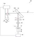
图1是表示第一实施方式的自相关测量装置1A的构成的图。FIG. 1 is a diagram showing the configuration of an
图2是表示由第一实施方式的自相关测量装置1A的检测部50求取的SHG自相关波形的一例的图。FIG. 2 is a diagram showing an example of the SHG autocorrelation waveform obtained by the
图3是表示第二实施方式的自相关测量装置1B的构成的图。FIG. 3 is a diagram showing the configuration of an
图4是表示第三实施方式的自相关测量装置1C的构成的图。FIG. 4 is a diagram showing the configuration of an
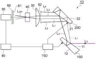
图5是表示第四实施方式的自相关测量装置1D的构成的图。FIG. 5 is a diagram showing the configuration of an
图6是表示第五实施方式的自相关测量装置1E的构成的图。FIG. 6 is a diagram showing the configuration of an
图7是表示由第五实施方式的自相关测量装置1E的检测部50求取的条纹分辨(fringe-resolved)SHG自相关波形的一例的图。FIG. 7 is a diagram showing an example of a fringe-resolved SHG autocorrelation waveform obtained by the
图8是表示第六实施方式的自相关测量装置1F的构成的图。FIG. 8 is a diagram showing the configuration of an
具体实施方式Detailed ways
以下参照附图详细说明用于实施本发明的方式。另外,附图的说明中对相同的部件标注相同的附图标记,省略重复说明。本发明并不限定于这些例示。Modes for carrying out the present invention will be described in detail below with reference to the accompanying drawings. In addition, in description of drawing, the same code|symbol is attached|subjected to the same member, and repeated description is abbreviate|omitted. The present invention is not limited to these examples.
(第一实施方式)(first embodiment)
图1是表示第一实施方式的自相关测量装置1A的构成的图。自相关测量装置1A包括第一反射部件10A、第二反射部件20A、聚光部30、非线性光学结晶40、检测部50、过滤部60、孔隙部61、延迟调整部70A和分析部80。FIG. 1 is a diagram showing the configuration of an
第一反射部件10A包括:具有使入射脉冲光L0的一部分反射的第一反射面11的第一平板13;具有使该入射脉冲光L0中的透过第一反射面11的光反射的第二反射面12的第二平板14。第一平板13的第一反射面11和第二平板14的第二反射面12彼此相对,且彼此平行。第一反射面11与第二反射面12之间的光程长(即,第一平板13与第二平板14之间的间隔)是可变的,可以由延迟调整部70A设定。第一平板13和第二平板14由对于入射脉冲光L0为透明的材料(例如合成石英、BK7)形成。The first reflecting
第二反射部件20A是包括使从第一反射部件10A出射的光的一部分反射的第一反射面21和使该光中透过第一反射面21的光反射的第二反射面22的平板。第二反射部件20A的第一反射面21和第二反射面22彼此平行,但第一反射部件10A的第一反射面11和第二反射面12不平行。第二反射部件20A由对于入射脉冲光L0为透明的材料(例如石英玻璃、BK7)形成。The
入射脉冲光L0透过第二反射部件20A而入射至第一反射部件10A。此时,将在第一反射部件10A的第一反射面11和第二反射部件20A的第二反射面22反射的光作为第一脉冲光L1,将在第一反射部件10A的第二反射面12和第二反射部件20A的第一反射面21反射的光作为第二脉冲光L2。在聚光部30,第一脉冲光L1和第二脉冲光L2各自的光束彼此不重叠。聚光部30对这些第一脉冲光L1和第二脉冲光L2进行聚光。构成聚光部30的聚光光学系统可以是透镜,也可以是凹面镜。The incident pulse light L0 is incident on the
非线性光学结晶40配置于由聚光部30产生的聚光位置,通过第一脉冲光L1和第二脉冲光L2的入射而产生二次谐波光LSH。入射至非线性光学结晶40的第一脉冲光L1和第二脉冲光L2是彼此非同轴的。作为非线性光学结晶40,例如能够使用BBO(β-BaB2O4)、LBO(LiB3O5)、KTO(KTaO3)、KDP(KH2PO4)等。此外,向非线性光学结晶40的第一脉冲光L1和第二脉冲光L2的入射设定成满足第一种相位匹配条件。The nonlinear
过滤部60和孔隙部61设置于非线性光学结晶40与检测部50之间。过滤部60阻隔入射脉冲光L0的波长成分(基波成分),使二次谐波光LSH透过。孔隙部61选择性地使从非线性光学结晶40出射的光中的基于第一脉冲光L1和第二脉冲光L2的相关的二次谐波光LSH向检测部50通过。检测部50检测基于第一脉冲光L1和第二脉冲光L2的相关的二次谐波光LSH的强度。作为构成检测部50的光检测器,例如使用光电倍增管、光电二极管等。The
延迟调整部70A通过使第一平板13与第二平板14之间的间隔变化,使第一反射部件10A的第一反射面11与第二反射面12之间的光程长变化,由此,使入射至非线性光学结晶40的第一脉冲光L1与第二脉冲光L2之间的延迟时间τ变化。延迟调整部70A可以使第一平板13和第二平板14两者移动,也可以使第一平板13和第二平板14中的任一者移动。作为延迟调整部70A,例如使用移动台、压电元件和扬声器等。根据这样的延迟调整部70A,能够使延迟时间τ连续变化。The
分析部80取得通过延迟调整部70A使延迟时间τ变化、并且设定成各延迟时间τ时的检测部50的检测结果(二次谐波光LSH的强度ISH(τ))。分析部80基于延迟时间τ与二次谐波光强度ISH(τ)的关系,求取由下述(1)式表示的SHG自相关函数G2(τ),求取入射脉冲光L0的脉冲宽度。I(t)如下述(2)式所示是与入射脉冲光L0的电场振幅E(t)的绝对值的平方成比例的值,即,是表示入射脉冲光L0的强度的值,如下述(3)式所示进行标准化。t是时间变量。The
[式1][Formula 1]

[式2][Formula 2]
I(t)∝|E(t)|2……(2)I(t)∝|E(t)|2 …(2)
[式3][Formula 3]

图2是表示由第一实施方式的自相关测量装置1A的检测部50求取的SHG自相关波形的一例的图。横轴是由延迟调整部70A设定的延迟时间(Time Delay)τ,对应于第一反射部件10A的第一反射面11与第二反射面12之间的光程长。FIG. 2 is a diagram showing an example of the SHG autocorrelation waveform obtained by the
如该图所示,延迟时间τ为0时,入射至非线性光学结晶40的第一脉冲光L1与第二脉冲光L2的时间重叠最大,因此SHG自相关信号的强度(Intensity)最大。随着延迟时间τ的绝对值变大,入射至非线性光学结晶40的第一脉冲光L1与第二脉冲光L2的时间重叠变小,因此SHG自相关信号的强度也变小。在SHG自相关波形的半峰全宽与入射脉冲光L0的脉冲宽度(半峰全宽)之间,存在依赖于入射脉冲光L0的脉冲波形的一定的关系。因此,能够基于SHG自相关函数的形状求取入射脉冲光L0的脉冲宽度。另外,该方法被称为非共线SHG自相关法。As shown in the figure, when the delay time τ is 0, the time overlap between thefirst pulsed light L1 and thesecond pulsed light L2 incident on the nonlinear
本实施方式的自相关测量装置1A不是使将入射脉冲光L02分支后的第一脉冲光L1和第二脉冲光L2向彼此不同的方向出射,而是使两脉冲光成分向同方向出射,因此容易实现小型化。The
优选对在第一反射部件10A和第二反射部件20A的各自中使光透过或反射的任意面施以电介质多层膜,由此调整第一脉冲光L1和第二脉冲光L2各自的强度,此外,优选调整两脉冲光成分间的强度比。通过这样操作,能够使由检测部50检测的二次谐波光LSH的强度较大。Preferably, each of thefirst pulsed light L1 and thesecond pulsed light L2 is adjusted by applying a dielectric multilayer film to any surface of the
例如,在第一反射部件10A的第一平板13和第二平板14以及第二反射部件20A的任何面均没有形成电介质多层膜,使各面的反射率为4%。此外,使入射脉冲光L0的强度为100mW。此时,第一脉冲光L1的强度为0.136mW,第二脉冲光L2的强度为0.125mW。For example, the dielectric multilayer film is not formed on any surface of the first
相对于此,通过适当地施以电介质多层膜,使第一平板13的第一反射面11的反射率为40%,使第一平板13的另一面(与第二反射部件20A相对的面)的反射率为0%,使第二平板14的第二反射面12的反射率为100%,使第二反射部件20A的第一反射面21的反射率为50%。不对第二反射部件20A的第二反射面22施以电介质多层膜,使第二反射面22的反射率为4%。此时,第一脉冲光L1的强度为8.8mW,第二脉冲光L2的强度为8.6mW。On the other hand, by appropriately applying a dielectric multilayer film, the reflectance of the
二次谐波光LSH的强度与第一脉冲光L1的强度和第二脉冲光L2的强度的积成比例,因此通过如上所述适当地施以电介质多层膜,变大至约4450(=(8.8×8.6)/(0.136×0.125))倍。The intensity of the second harmonic light LSH is proportional to the product of the intensity of the first pulse light L1 and the intensity of the second pulse light L2 , and thus becomes large to about approx. 4450 (=(8.8×8.6)/(0.136×0.125)) times.
(第二实施方式)(Second Embodiment)
图3是表示第二实施方式的自相关测量装置1B的构成的图。自相关测量装置1B包括第一反射部件10B、第二反射部件20A、聚光部30、非线性光学结晶40、检测部50、过滤部60、孔隙部61、延迟调整部70B和分析部80。FIG. 3 is a diagram showing the configuration of an
与图1所示的第一实施方式的自相关测量装置1A的构成相比较,图3所示的第二实施方式的自相关测量装置1B的不同点在于,代替第一反射部件10A,具有第一反射部件10B,代替延迟调整部70A,具有延迟调整部70B。Compared with the configuration of the
第一反射部件10B具有设置于第一反射面11与第二反射面12之间的折射率可变部件15。折射率可变部件15的折射率根据施加电压值而变化。作为折射率可变部件15,能够使用液晶、非线性光学结晶(例如LN(LiNbO3)和KTN(KTa1-xNbxO3)等),此时,能够使彼此相对的2个主面为第一反射面11和第二反射面12。此外,作为折射率可变部件15能够使用相位调制型的空间光调制器,此时,能够使空间光调制器的CMOS芯片部和玻璃基板端面为第一反射面11和第二反射面12。The
延迟调整部70B通过使施加于折射率可变部件15的电压值变化,使第一反射部件10B的第一反射面11与第二反射面12之间的光程长变化,由此,使入射至非线性光学结晶40的第一脉冲光L1与第二脉冲光L2之间的延迟时间τ变化。延迟调整部70B能够使延迟时间τ连续且高速地变化。The
本实施方式的自相关测量装置1B也不是使将入射脉冲光L02分支后的第一脉冲光L1和第二脉冲光L2向彼此不同的方向出射,而是使两脉冲光成分向同方向出射,因此容易实现小型化。The
此外,在本实施方式中,优选通过对在第一反射部件10B和第二反射部件20A的各自中使光透过或反射的任意面施以电介质多层膜,调整第一脉冲光L1和第二脉冲光L2各自的强度,此外,优选调整两脉冲光成分之间的强度比。通过这样操作,能够使由检测部50检测的二次谐波光LSH的强度较大。In addition, in the present embodiment, it is preferable to adjust the first pulsed light L1 and the The respective intensities of the second pulse light L2 , and the intensity ratio between the two pulse light components is preferably adjusted. By doing so, the intensity of the second harmonic light LSH detected by the
(第三实施方式)(third embodiment)
图4是表示第三实施方式的自相关测量装置1C的构成的图。自相关测量装置1C包括第一反射部件10A、第二反射部件20A、聚光部30、非线性光学结晶40、检测部50、过滤部60、孔隙部61、延迟调整部70C和分析部80。FIG. 4 is a diagram showing the configuration of an
与图1所示的第一实施方式的自相关测量装置1A的构成进行比较,图4所示的第三实施方式的自相关测量装置1C的不同点在于,代替延迟调整部70A,具有延迟调整部70C。Compared with the configuration of the
延迟调整部70C包括第一旋转台71和第二旋转台72。第一旋转台71使第二反射部件20A转动。第二旋转台72使第二反射部件20A、聚光部30、非线性光学结晶40、检测部50、过滤部60和孔隙部61一体地转动。第一旋转台71和第二旋转台72各自的转动中心是第二反射部件20A的第一反射面21中的第一脉冲光L1和第二脉冲光L2各自的出射位置的中心位置。The retardation adjustment unit 70C includes a first turntable 71 and a
通过第一旋转台71和第二旋转台72各自的转动,在第二反射部件20A只转动角度θ时,聚光部30、非线性光学结晶40、检测部50、过滤部60和孔隙部61一体地只转动角度2θ。包括第一旋转台71和第二旋转台72的延迟调整部70C使该转动的角度θ变化,由此使第二反射部件20A的第一反射面21与第二反射面22之间的第一脉冲光L1的光程长变化,由此,使入射至非线性光学结晶40的第一脉冲光L1与第二脉冲光L2之间的延迟时间τ变化。When the second
本实施方式的自相关测量装置1C也不是使将入射脉冲光L02分支后的第一脉冲光L1和第二脉冲光L2向彼此不同的方向出射,而是使两脉冲光成分向同方向出射,因此容易实现小型化。The
(第四实施方式)(Fourth Embodiment)
图5是表示第四实施方式的自相关测量装置1D的构成的图。自相关测量装置1D包括第一反射部件10D、第二反射部件20D、聚光部30、非线性光学结晶40、检测部50、过滤部60、孔隙部61、62、延迟调整部70D和分析部80。FIG. 5 is a diagram showing the configuration of an
与图1所示的第一实施方式的自相关测量装置1A的构成相比较,图5所示的第四实施方式的自相关测量装置1D的不同点在于,代替第一反射部件10A,具有第一反射部件10D,代替第二反射部件20A,具有第二反射部件20D。此外,第四实施方式的自相关测量装置1D的不同点在于,还具有孔隙部62,代替延迟调整部70A,具有延迟调整部70D。Compared with the configuration of the
第一反射部件10D是具有彼此相对的2个主面作为第一反射面11和第二反射面12的平板,第一反射面11和第二反射面12彼此是不平行的。第二反射部件20D是具有彼此相对的2个主面作为第一反射面21和第二反射面22的平板,第一反射面21和第二反射面22彼此是不平行的。The
延迟调整部70D通过使第一反射部件10D在与第一反射面11平行的方向上移动,能够使第一反射部件10D的第一反射面11与第二反射面12之间的第二脉冲光L2的光程长变化。延迟调整部70D通过使第二反射部件20D在与第一反射面21平行的方向上移动,能够使第二反射部件20D的第一反射面21与第二反射面22之间的第一脉冲光L1的光程长变化。延迟调整部70D通过使第一反射部件10D和第二反射部件20D的两者或任一者移动,使入射至非线性光学结晶40的第一脉冲光L1与第二脉冲光L2之间的延迟时间τ变化。The
孔隙部62设置于第二反射部件20D与非线性光学结晶40之间,优选设置于第二反射部件20D与聚光部30之间。孔隙部62使在第一反射部件10D的第一反射面11和第二反射部件20D的第二反射面22反射的第一脉冲光L1通过,并且使在第一反射部件10D的第二反射面12和第二反射部件20D的第一反射面21反射的第二脉冲光L2通过。另一方面,孔隙部62阻隔在第一反射部件10D的第一反射面11和第二反射部件20D的第一反射面21反射的脉冲光L3,并且阻隔在第一反射部件10D的第二反射面12和第二反射部件20D的第二反射面22反射的脉冲光L4。即,孔隙部62使在相关测量时成为噪声的脉冲光L3和脉冲光L4不入射至非线性光学结晶40。The
本实施方式的自相关测量装置1D也不使将入射脉冲光L02分支后的第一脉冲光L1和第二脉冲光L2向彼此不同的方向出射,而使两脉冲光成分向同方向出射,因此容易实现小型化。The
(第五实施方式)(Fifth Embodiment)
图6是表示第五实施方式的自相关测量装置1E的构成的图。自相关测量装置1E包括第一反射部件10A、第二反射部件20A、聚光部30、非线性光学结晶40、检测部50、过滤部60、孔隙部63、延迟调整部70A和分析部80。FIG. 6 is a diagram showing the configuration of an
与图1所示的第一实施方式的自相关测量装置1A的构成相比较,图6所示的第五实施方式的自相关测量装置1E的不同点在于,入射脉冲光L0的光束径的大小不同,代替孔隙部61具有孔隙部63,而且分析部80的处理内容不同。Compared with the configuration of the
在第一~第四实施方式中,入射脉冲光L0的光束径是从第二反射部件出射的第一脉冲光L1和第二脉冲光L2各自的光束在空间上不重叠的程度。相对于此,在第五实施方式中,入射脉冲光L0的光束径是从第二反射部件出射的第一脉冲光L1和第二脉冲光L2各自的光束在空间上彼此重叠的程度,In the first to fourth embodiments, the beam diameter of the incident pulsed lightL0 is such that the respective light beams of thefirst pulsed light L1 and thesecond pulsed light L2 emitted from the second reflection member do not overlap in space. On the other hand, in the fifth embodiment, the beam diameter of the incident pulsed lightL0 is such that the respective light beams of thefirst pulsed light L1 and thesecond pulsed light L2 emitted from the second reflection member overlap each other in space. ,
孔隙部63设置在第二反射部件20A与非线性光学结晶40之间,优选设置在第二反射部件20A与聚光部30之间。孔隙部63选择性地使第一脉冲光L1和第二脉冲光L2各自的光束在空间上彼此重叠的部分通过。The
非线性光学结晶40配置于由聚光部30产生的聚光位置,通过第一脉冲光L1和第二脉冲光L2的入射而产生二次谐波光LSH。在本实施方式中,在非线性光学结晶40产生的二次谐波光LSH不仅是基于第一脉冲光L1和第二脉冲光L2的相关的二次谐波光,也包括仅基于第一脉冲光L1的二次谐波光和仅基于第二脉冲光L2的二次谐波光。检测部50检测这些二次谐波光的强度。The nonlinear
分析部80取得利用延迟调整部70A使延迟时间τ变化并且设定成各延迟时间τ时的检测部50的检测结果(二次谐波光LSH的强度ISH(τ))。然后,分析部80基于延迟时间τ与二次谐波光强度ISH(τ)的关系,求取由下述(4)式表示的SHG自相关函数S2(τ),求取入射脉冲光L0的脉冲宽度。该式的右边第三项由下述(5)式表示,右边第四项由下述(6)式表示。ω0是入射脉冲光的中心角频率。The
[式4][Formula 4]
S2(τ)=1+2G2(τ)+4Re[F1(τ)exp(-iω0τ)]+Re[F2(τ)exp(-2iω0τ)]……(4)S2 (τ)=1+2G2 (τ)+4Re[F1 (τ)exp(-iω0 τ)]+Re[F2 (τ)exp(-2iω0 τ)]...(4)
[式5][Formula 5]

[式6][Formula 6]

图7是表示由第五实施方式的自相关测量装置1E的检测部50求取的SHG自相关波形的一例的图。横轴是由延迟调整部70A设定的延迟时间τ,对应于第一反射部件10A的第一反射面11与第二反射面12之间的光程长。FIG. 7 is a diagram showing an example of the SHG autocorrelation waveform obtained by the
如该图所示,在延迟时间τ为0时,入射至非线性光学结晶40的第一脉冲光L1和第二脉冲光L2的时间上的重叠最大,因此SHG自相关函数的包络函数的值最大。随着延迟时间τ的绝对值变大,入射至非线性光学结晶40的第一脉冲光L1和第二脉冲光L2的时间上的重叠变小,因此包络函数的值也变小。在包络函数的半峰全宽与入射脉冲光L0的脉冲宽度(半峰全宽)之间,存在依赖于入射脉冲光L0的脉冲波形的一定的关系。由此,能够基于包络函数的形状求取入射脉冲光L0的脉冲宽度。另外,该方法被称为条纹分辨SHG自相关法。As shown in the figure, when the delay time τ is 0, the temporal overlap of thefirst pulsed light L1 and thesecond pulsed light L2 incident on the nonlinear
本实施方式的自相关测量装置1E也不使将入射脉冲光L02分支后的第一脉冲光L1和第二脉冲光L2向彼此不同的方向出射,而使两脉冲光成分向同方向出射,因此容易实现小型化。The
(第六实施方式)(Sixth Embodiment)
图8是表示第六实施方式的自相关测量装置1F的构成的图。与图1所示的第一实施方式的自相关测量装置1A的构成相比较,图8所示的第六实施方式的自相关测量装置1F的不同点在于,作为检测部50使用分光器,而且分析部80的处理内容不同。FIG. 8 is a diagram showing the configuration of an
本实施方式中,检测部50对基于第一脉冲光L1和第二脉冲光L2的相关的二次谐波光LSH的光谱进行检测。分析部80取得利用延迟调整部70A使延迟时间τ变化并且设定成各延迟时间τ时的检测部50的检测结果(二次谐波光LSH的光谱)。然后,分析部80基于延迟时间τ与二次谐波光的光谱的关系,求取入射脉冲光L0的振幅分布和相位分布两者的信息。另外,该方法被称为频率分辨光栅。In the present embodiment, the
(其它实施方式)(Other Embodiments)
本发明并不限定于上述实施方式,能够进行各种变形。例如,在第五和第六实施方式中,作为使入射至非线性光学结晶40的第一脉冲光L1与第二脉冲光L2之间的延迟时间τ变化的方法,能够采用在第二~第四实施方式中说明的方法。The present invention is not limited to the above-described embodiments, and various modifications are possible. For example, in the fifth and sixth embodiments, as a method of changing the delay time τ between thefirst pulsed light L1 and thesecond pulsed light L2 incident on the nonlinear
上述实施方式的自相关测量装置构成为包括:(1)第一反射部件,其具有使入射脉冲光的一部分反射的第一反射面和使该入射脉冲光中透过该第一反射面的光反射的第二反射面;(2)第二反射部件,其具有使从第一反射部件出射的光的一部分反射的第一反射面和使该光中透过该第一反射面的光反射的第二反射面;(3)聚光部,其对在第一反射部件的第一反射面和第二反射部件的第二反射面反射的第一脉冲光和在第一反射部件的第二反射面和第二反射部件的第一反射面反射的第二脉冲光进行聚光;(4)非线性光学结晶,其配置于由聚光部产生的聚光位置,通过第一脉冲光和第二脉冲光的入射而产生二次谐波光;(5)检测部,其对二次谐波光进行检测;(6)延迟调整部,其使入射至非线性光学结晶的第一脉冲光与第二脉冲光之间的延迟时间变化;和(7)分析部,其基于由延迟调整部设定的延迟时间与检测部的检测结果的关系,求取入射脉冲光的脉冲宽度。The autocorrelation measurement device of the above-described embodiment is configured to include: (1) a first reflection member having a first reflection surface that reflects a part of incident pulsed light, and light that transmits light of the incident pulsed light through the first reflection surface a second reflecting surface that reflects; (2) a second reflecting member having a first reflecting surface that reflects a part of the light emitted from the first reflecting member and a first reflecting surface that reflects light passing through the first reflecting surface among the light The second reflection surface; (3) the light collecting part, which reflects the first pulse light reflected on the first reflection surface of the first reflection member and the second reflection surface of the second reflection member and the second reflection on the first reflection member The second pulsed light reflected by the surface and the first reflection surface of the second reflection member is concentrated; (4) a nonlinear optical crystal, which is arranged at the light-condensing position generated by the light-condensing part, and passes the first pulsed light and the second pulsed light. The second harmonic light is generated by the incidence of the pulsed light; (5) the detection part detects the second harmonic light; (6) the retardation adjustment part makes the first pulsed light incident on the nonlinear optical crystal and the second harmonic light and (7) an analysis section that obtains the pulse width of the incident pulse light based on the relationship between the delay time set by the delay adjustment section and the detection result of the detection section.
在上述装置中可以采用下述构成:对在第一反射部件和第二反射部件的各自中使光透过或反射的任意面,施以用于调整第一脉冲光与第二脉冲光之间的强度比的电介质多层膜。In the above-mentioned device, a configuration may be adopted for adjusting the distance between the first pulsed light and the second pulsed light to any surface that transmits or reflects light in each of the first reflection member and the second reflection member. The strength ratio of the dielectric multilayer film.
上述装置中可以采用下述构成:第一反射部件包括:具有第一反射面的第一平板;和与该第一平板平行地配置且具有第二反射面的第二平板,延迟调整部使第一平板与第二平板之间的间隔变化而使延迟时间变化。In the above-mentioned device, the following structure may be adopted: the first reflecting member includes: a first flat plate having a first reflecting surface; and a second flat plate having a second reflecting surface arranged in parallel with the first flat plate, and the retardation adjusting portion makes the first plate The delay time varies as the interval between one plate and the second plate varies.
此外,上述装置中可以采用下述构成:第一反射部件包括折射率可变部件,其设置于第一反射面与第二反射面之间且折射率根据施加电压值而变化,延迟调整部使施加于折射率可变部件的电压值变化而使延迟时间变化。In addition, in the above-mentioned apparatus, the first reflection member may include a variable refractive index member, which is provided between the first reflection surface and the second reflection surface, and the refractive index is changed according to the value of the applied voltage, and the retardation adjusting portion makes The delay time is changed by changing the voltage value applied to the variable refractive index member.
上述装置中可以采用下述构成:入射至非线性光学结晶的第一脉冲光和第二脉冲光彼此是非同轴的,在非线性光学结晶与检测部之间设置有孔隙部,该孔隙部选择性地使从非线性光学结晶出射的光中基于第一脉冲光和第二脉冲光的相关的二次谐波光向检测部通过,检测部检测二次谐波光的强度。此时,能够通过非共线SHG自相关法求取入射脉冲光的脉冲宽度。The above-mentioned device may adopt the following structure: the first pulse light and the second pulse light incident on the nonlinear optical crystal are non-coaxial with each other, and an aperture portion is provided between the nonlinear optical crystal and the detection portion, and the aperture portion selects The second harmonic light based on the correlation of the first pulsed light and the second pulsed light among the light emitted from the nonlinear optical crystal is selectively passed to the detection unit, and the detection unit detects the intensity of the second harmonic light. In this case, the pulse width of the incident pulse light can be obtained by the non-collinear SHG autocorrelation method.
在上述装置中可以采用下述构成:在第二反射部件与非线性光学结晶之间设置有孔隙部,该孔隙部选择性地使第一脉冲光和第二脉冲光各自的光束在空间上彼此重叠的部分通过,检测部检测二次谐波光的强度。此时,能够通过条纹分辨SHG自相关法求取入射脉冲光的脉冲宽度。In the above-mentioned apparatus, a configuration may be adopted in which an aperture portion is provided between the second reflection member and the nonlinear optical crystal, and the aperture portion selectively causes the respective light beams of the first pulsed light and the second pulsed light to be spatially separated from each other. The overlapping portion passes through, and the detection unit detects the intensity of the second harmonic light. In this case, the pulse width of the incident pulse light can be obtained by the fringe-resolved SHG autocorrelation method.
在上述装置中可以采用下述构成:入射至非线性光学结晶的第一脉冲光和第二脉冲光彼此是非同轴的,在非线性光学结晶与检测部之间设置有孔隙部,该孔隙部选择性地使从非线性光学结晶出射的光中基于第一脉冲光和第二脉冲光的相关的二次谐波光向检测部通过,检测部检测二次谐波光的光谱。此时,能够通过频率分解光栅求取入射脉冲光的振幅分布和相位分布两者的信息。In the above-mentioned device, the first pulse light and the second pulse light incident on the nonlinear optical crystal are non-coaxial with each other, and a hole is provided between the nonlinear optical crystal and the detection part, and the hole is The second harmonic light based on the correlation of the first pulsed light and the second pulsed light among the lights emitted from the nonlinear optical crystal is selectively passed to the detection unit, and the detection unit detects the spectrum of the second harmonic light. In this case, information on both the amplitude distribution and the phase distribution of the incident pulse light can be obtained by the frequency decomposition grating.
工业上的可利用性industrial availability
本发明可以用作能够小型化的自相关测量装置。The present invention can be used as an autocorrelation measurement device that can be miniaturized.
附图标记说明Description of reference numerals
1A~1F……自相关测量装置,10A、10B、10D……第一反射部件,11……第一反射面,12……第二反射面,13……第一平板,14……第二平板,15……折射率可变部件,20A、20D……第二反射部件,21……第一反射面,22……第二反射面,30……聚光部,40……非线性光学结晶,50……检测部,60……过滤部,61~63……孔隙部,70A~70D……延迟调整部,71……第一旋转台,72……第二旋转台,80……分析部,L0……入射脉冲光,L1……第一脉冲光,L2……第二脉冲光,LSH……二次谐波光。1A~1F...autocorrelation measuring device, 10A, 10B, 10D...first reflecting member, 11...first reflecting surface, 12...second reflecting surface, 13...first flat plate, 14...second Flat plate, 15... Refractive index variable member, 20A, 20D... Second reflecting member, 21... First reflecting surface, 22... Second reflecting surface, 30... Condensing section, 40... Nonlinear optics Crystal, 50...detection part, 60...filter part, 61-63...pore part, 70A-70D...retardation adjustment part, 71...first turntable, 72...second turntable, 80... Analysis part, L0 : incident pulse light, L1 : first pulse light, L2 : second pulse light, LSH : second harmonic light.
Claims (13)
Translated fromChineseApplications Claiming Priority (3)
| Application Number | Priority Date | Filing Date | Title |
|---|---|---|---|
| JP2015-166465 | 2015-08-26 | ||
| JP2015166465AJP6549448B2 (en) | 2015-08-26 | 2015-08-26 | Auto correlation measurement device |
| PCT/JP2016/074672WO2017033974A1 (en) | 2015-08-26 | 2016-08-24 | Autocorrelation measurement device |
Publications (2)
| Publication Number | Publication Date |
|---|---|
| CN107923798A CN107923798A (en) | 2018-04-17 |
| CN107923798Btrue CN107923798B (en) | 2020-06-23 |
Family
ID=58100327
Family Applications (1)
| Application Number | Title | Priority Date | Filing Date |
|---|---|---|---|
| CN201680048824.3AExpired - Fee RelatedCN107923798B (en) | 2015-08-26 | 2016-08-24 | Autocorrelation measuring device |
Country Status (6)
| Country | Link |
|---|---|
| US (1) | US10337928B2 (en) |
| JP (1) | JP6549448B2 (en) |
| KR (1) | KR102723216B1 (en) |
| CN (1) | CN107923798B (en) |
| DE (1) | DE112016003846T5 (en) |
| WO (1) | WO2017033974A1 (en) |
Families Citing this family (2)
| Publication number | Priority date | Publication date | Assignee | Title |
|---|---|---|---|---|
| CN109506792A (en)* | 2019-01-16 | 2019-03-22 | 中国工程物理研究院激光聚变研究中心 | A kind of single-shot time autocorrelation function analyzer |
| KR102764232B1 (en)* | 2022-10-31 | 2025-02-05 | 건국대학교 글로컬산학협력단 | Apparatus switchable to optical delay line device and autocorrelator device and operation methods |
Citations (5)
| Publication number | Priority date | Publication date | Assignee | Title |
|---|---|---|---|---|
| US3520616A (en)* | 1968-01-04 | 1970-07-14 | United Aircraft Corp | Optical pulse measurement system |
| US4480192A (en)* | 1982-02-16 | 1984-10-30 | The University Of Rochester | Optical pulse correlation measurement |
| CN101900608A (en)* | 2010-06-23 | 2010-12-01 | 中国计量科学研究院 | Multifunctional large-range ultrashort pulse laser autocorrelator |
| CN102636272A (en)* | 2012-03-22 | 2012-08-15 | 中国科学院上海光学精密机械研究所 | Femtosecond laser pulse measurement method based on transient grating effect and device |
| CN103698025A (en)* | 2013-12-30 | 2014-04-02 | 上海交通大学 | Domain wall-based nonlinear impulse autocorrelation measuring method and measuring device |
Family Cites Families (9)
| Publication number | Priority date | Publication date | Assignee | Title |
|---|---|---|---|---|
| US5033853A (en)* | 1989-04-10 | 1991-07-23 | Coherent, Inc. | Apparatus for autocorrelating optical radiation signals |
| JPH07270246A (en) | 1994-03-31 | 1995-10-20 | Tera Tec:Kk | Indirect measuring device for width of pulse of ultrashort optical pulse |
| JP3378502B2 (en) | 1998-05-15 | 2003-02-17 | 日本電信電話株式会社 | Optical signal waveform measurement method |
| JP2001074560A (en) | 1999-06-30 | 2001-03-23 | Oyo Koden Kenkyushitsu:Kk | Interferometer, optical pulse width measuring device, and optical pulse width measuring method using the same |
| JP3736410B2 (en) | 2001-09-27 | 2006-01-18 | 独立行政法人理化学研究所 | Autocorrelator |
| US7230715B2 (en)* | 2004-12-07 | 2007-06-12 | Matsushita Electric Industrial Co., Ltd. | Ultrafast laser pulse shape measurement method and system |
| JP2009008419A (en) | 2007-06-26 | 2009-01-15 | Canon Machinery Inc | Method and apparatus for checking pulse width |
| US9347832B2 (en)* | 2008-05-15 | 2016-05-24 | Bodkin Design And Engineering Llc | Optical systems and methods employing a polarimetric optical filter |
| WO2012024110A1 (en) | 2010-08-20 | 2012-02-23 | Swamp Optics | Extreme light pulse-front tilt and its application to single shot measurement of picosecond to nanosecond laser pulses |
- 2015
- 2015-08-26JPJP2015166465Apatent/JP6549448B2/ennot_activeExpired - Fee Related
- 2016
- 2016-08-24WOPCT/JP2016/074672patent/WO2017033974A1/ennot_activeCeased
- 2016-08-24USUS15/754,377patent/US10337928B2/enactiveActive
- 2016-08-24KRKR1020187003105Apatent/KR102723216B1/enactiveActive
- 2016-08-24CNCN201680048824.3Apatent/CN107923798B/ennot_activeExpired - Fee Related
- 2016-08-24DEDE112016003846.1Tpatent/DE112016003846T5/enactivePending
Patent Citations (5)
| Publication number | Priority date | Publication date | Assignee | Title |
|---|---|---|---|---|
| US3520616A (en)* | 1968-01-04 | 1970-07-14 | United Aircraft Corp | Optical pulse measurement system |
| US4480192A (en)* | 1982-02-16 | 1984-10-30 | The University Of Rochester | Optical pulse correlation measurement |
| CN101900608A (en)* | 2010-06-23 | 2010-12-01 | 中国计量科学研究院 | Multifunctional large-range ultrashort pulse laser autocorrelator |
| CN102636272A (en)* | 2012-03-22 | 2012-08-15 | 中国科学院上海光学精密机械研究所 | Femtosecond laser pulse measurement method based on transient grating effect and device |
| CN103698025A (en)* | 2013-12-30 | 2014-04-02 | 上海交通大学 | Domain wall-based nonlinear impulse autocorrelation measuring method and measuring device |
Also Published As
| Publication number | Publication date |
|---|---|
| KR102723216B1 (en) | 2024-10-30 |
| US10337928B2 (en) | 2019-07-02 |
| JP2017044551A (en) | 2017-03-02 |
| KR20180042234A (en) | 2018-04-25 |
| JP6549448B2 (en) | 2019-07-24 |
| DE112016003846T5 (en) | 2018-05-09 |
| WO2017033974A1 (en) | 2017-03-02 |
| US20180245984A1 (en) | 2018-08-30 |
| CN107923798A (en) | 2018-04-17 |
Similar Documents
| Publication | Publication Date | Title |
|---|---|---|
| CN108885138B (en) | Pulse light waveform measuring method and waveform measuring device | |
| JP6220128B2 (en) | Terahertz wave generator and terahertz wave measuring method | |
| JP5265351B2 (en) | Measurement of ultrashort light pulses using thick nonlinear crystals. | |
| WO2021117632A1 (en) | Quantum absorption spectroscopy system and quantum absorption spectroscopy method | |
| JP5216544B2 (en) | Terahertz wave generator | |
| EP2304412A1 (en) | System for generating raman vibrational analysis signals | |
| CN108107008B (en) | Time domain heat reflection spectrum measuring system | |
| US6204926B1 (en) | Methods and system for optically correlating ultrashort optical waveforms | |
| Krebs et al. | Sub-20 fs pulses shaped directly in the UV by an acousto-optic programmable dispersive filter | |
| CN107923798B (en) | Autocorrelation measuring device | |
| Lerch et al. | Experimental requirements for entangled two-photon spectroscopy | |
| CN100432643C (en) | Femtosecond laser camera | |
| CN119009630A (en) | Terahertz generation detection integrated system based on lithium niobate thin film | |
| CN114001823B (en) | A method and device for measuring the characteristics of two-color ultrashort laser pulses | |
| CN114942080B (en) | Ultrashort pulse measurement device and method based on transient grating modulation sampling | |
| JP7456639B2 (en) | spectrometer | |
| JP7110686B2 (en) | Concentration measuring device | |
| CN105806494A (en) | An OPO ultrashort pulse laser pulse width cross-correlation measurement system | |
| CN100514013C (en) | Measurement device for ultrashort pulse frequency-resolved optical opening method | |
| JP3440273B2 (en) | Nonlinear susceptibility spectrum measuring method and device | |
| Junaid et al. | Point-spread function engineering in upconversion imaging | |
| JPH0694571A (en) | Optical response speed measuring device | |
| Schweinberger et al. | Grating-Based Mid-Infrared Long-Pass Filter for High-Power Applications | |
| Lee et al. | Extremely simple device for measuring ultrashort pulses in the visible | |
| McGowan et al. | Continuously tunable femtosecond pulses covering 2· 1–2· 5 μm from an optical parametric oscillator based on RbTiOAsO4 |
Legal Events
| Date | Code | Title | Description |
|---|---|---|---|
| PB01 | Publication | ||
| PB01 | Publication | ||
| SE01 | Entry into force of request for substantive examination | ||
| SE01 | Entry into force of request for substantive examination | ||
| GR01 | Patent grant | ||
| GR01 | Patent grant | ||
| CF01 | Termination of patent right due to non-payment of annual fee | Granted publication date:20200623 | |
| CF01 | Termination of patent right due to non-payment of annual fee |