CN107921612B - Tapered blade driver and fastener - Google Patents
Tapered blade driver and fastenerDownload PDFInfo
- Publication number
- CN107921612B CN107921612BCN201680048353.6ACN201680048353ACN107921612BCN 107921612 BCN107921612 BCN 107921612BCN 201680048353 ACN201680048353 ACN 201680048353ACN 107921612 BCN107921612 BCN 107921612B
- Authority
- CN
- China
- Prior art keywords
- driver
- fastener
- drive
- angle
- radius
- Prior art date
- Legal status (The legal status is an assumption and is not a legal conclusion. Google has not performed a legal analysis and makes no representation as to the accuracy of the status listed.)
- Active
Links
Images


Classifications
- B—PERFORMING OPERATIONS; TRANSPORTING
- B25—HAND TOOLS; PORTABLE POWER-DRIVEN TOOLS; MANIPULATORS
- B25B—TOOLS OR BENCH DEVICES NOT OTHERWISE PROVIDED FOR, FOR FASTENING, CONNECTING, DISENGAGING OR HOLDING
- B25B15/00—Screwdrivers
- B25B15/001—Screwdrivers characterised by material or shape of the tool bit
- B25B15/004—Screwdrivers characterised by material or shape of the tool bit characterised by cross-section
- B25B15/005—Screwdrivers characterised by material or shape of the tool bit characterised by cross-section with cross- or star-shaped cross-section
- B—PERFORMING OPERATIONS; TRANSPORTING
- B25—HAND TOOLS; PORTABLE POWER-DRIVEN TOOLS; MANIPULATORS
- B25B—TOOLS OR BENCH DEVICES NOT OTHERWISE PROVIDED FOR, FOR FASTENING, CONNECTING, DISENGAGING OR HOLDING
- B25B15/00—Screwdrivers
- B—PERFORMING OPERATIONS; TRANSPORTING
- B25—HAND TOOLS; PORTABLE POWER-DRIVEN TOOLS; MANIPULATORS
- B25B—TOOLS OR BENCH DEVICES NOT OTHERWISE PROVIDED FOR, FOR FASTENING, CONNECTING, DISENGAGING OR HOLDING
- B25B15/00—Screwdrivers
- B25B15/02—Screwdrivers operated by rotating the handle
- B—PERFORMING OPERATIONS; TRANSPORTING
- B25—HAND TOOLS; PORTABLE POWER-DRIVEN TOOLS; MANIPULATORS
- B25B—TOOLS OR BENCH DEVICES NOT OTHERWISE PROVIDED FOR, FOR FASTENING, CONNECTING, DISENGAGING OR HOLDING
- B25B21/00—Portable power-driven screw or nut setting or loosening tools; Attachments for drilling apparatus serving the same purpose
- B—PERFORMING OPERATIONS; TRANSPORTING
- B25—HAND TOOLS; PORTABLE POWER-DRIVEN TOOLS; MANIPULATORS
- B25B—TOOLS OR BENCH DEVICES NOT OTHERWISE PROVIDED FOR, FOR FASTENING, CONNECTING, DISENGAGING OR HOLDING
- B25B23/00—Details of, or accessories for, spanners, wrenches, screwdrivers
- B—PERFORMING OPERATIONS; TRANSPORTING
- B25—HAND TOOLS; PORTABLE POWER-DRIVEN TOOLS; MANIPULATORS
- B25B—TOOLS OR BENCH DEVICES NOT OTHERWISE PROVIDED FOR, FOR FASTENING, CONNECTING, DISENGAGING OR HOLDING
- B25B23/00—Details of, or accessories for, spanners, wrenches, screwdrivers
- B25B23/0071—Abutment for screws or nuts
- F—MECHANICAL ENGINEERING; LIGHTING; HEATING; WEAPONS; BLASTING
- F16—ENGINEERING ELEMENTS AND UNITS; GENERAL MEASURES FOR PRODUCING AND MAINTAINING EFFECTIVE FUNCTIONING OF MACHINES OR INSTALLATIONS; THERMAL INSULATION IN GENERAL
- F16B—DEVICES FOR FASTENING OR SECURING CONSTRUCTIONAL ELEMENTS OR MACHINE PARTS TOGETHER, e.g. NAILS, BOLTS, CIRCLIPS, CLAMPS, CLIPS OR WEDGES; JOINTS OR JOINTING
- F16B23/00—Specially shaped nuts or heads of bolts or screws for rotations by a tool
- F16B23/0007—Specially shaped nuts or heads of bolts or screws for rotations by a tool characterised by the shape of the recess or the protrusion engaging the tool
- F16B23/003—Specially shaped nuts or heads of bolts or screws for rotations by a tool characterised by the shape of the recess or the protrusion engaging the tool star-shaped or multi-lobular, e.g. Torx-type, twelve-point star
- F—MECHANICAL ENGINEERING; LIGHTING; HEATING; WEAPONS; BLASTING
- F16—ENGINEERING ELEMENTS AND UNITS; GENERAL MEASURES FOR PRODUCING AND MAINTAINING EFFECTIVE FUNCTIONING OF MACHINES OR INSTALLATIONS; THERMAL INSULATION IN GENERAL
- F16B—DEVICES FOR FASTENING OR SECURING CONSTRUCTIONAL ELEMENTS OR MACHINE PARTS TOGETHER, e.g. NAILS, BOLTS, CIRCLIPS, CLAMPS, CLIPS OR WEDGES; JOINTS OR JOINTING
- F16B23/00—Specially shaped nuts or heads of bolts or screws for rotations by a tool
- F16B23/0053—Specially shaped nuts or heads of bolts or screws for rotations by a tool with a conical or prismatic recess for receiving a centering pin of the tool apparatus
- F—MECHANICAL ENGINEERING; LIGHTING; HEATING; WEAPONS; BLASTING
- F16—ENGINEERING ELEMENTS AND UNITS; GENERAL MEASURES FOR PRODUCING AND MAINTAINING EFFECTIVE FUNCTIONING OF MACHINES OR INSTALLATIONS; THERMAL INSULATION IN GENERAL
- F16B—DEVICES FOR FASTENING OR SECURING CONSTRUCTIONAL ELEMENTS OR MACHINE PARTS TOGETHER, e.g. NAILS, BOLTS, CIRCLIPS, CLAMPS, CLIPS OR WEDGES; JOINTS OR JOINTING
- F16B33/00—Features common to bolt and nut
- F16B33/02—Shape of thread; Special thread-forms
- F—MECHANICAL ENGINEERING; LIGHTING; HEATING; WEAPONS; BLASTING
- F16—ENGINEERING ELEMENTS AND UNITS; GENERAL MEASURES FOR PRODUCING AND MAINTAINING EFFECTIVE FUNCTIONING OF MACHINES OR INSTALLATIONS; THERMAL INSULATION IN GENERAL
- F16B—DEVICES FOR FASTENING OR SECURING CONSTRUCTIONAL ELEMENTS OR MACHINE PARTS TOGETHER, e.g. NAILS, BOLTS, CIRCLIPS, CLAMPS, CLIPS OR WEDGES; JOINTS OR JOINTING
- F16B35/00—Screw-bolts; Stay-bolts; Screw-threaded studs; Screws; Set screws
- F16B35/04—Screw-bolts; Stay-bolts; Screw-threaded studs; Screws; Set screws with specially-shaped head or shaft in order to fix the bolt on or in an object
- F16B35/041—Specially-shaped shafts
- F—MECHANICAL ENGINEERING; LIGHTING; HEATING; WEAPONS; BLASTING
- F16—ENGINEERING ELEMENTS AND UNITS; GENERAL MEASURES FOR PRODUCING AND MAINTAINING EFFECTIVE FUNCTIONING OF MACHINES OR INSTALLATIONS; THERMAL INSULATION IN GENERAL
- F16B—DEVICES FOR FASTENING OR SECURING CONSTRUCTIONAL ELEMENTS OR MACHINE PARTS TOGETHER, e.g. NAILS, BOLTS, CIRCLIPS, CLAMPS, CLIPS OR WEDGES; JOINTS OR JOINTING
- F16B35/00—Screw-bolts; Stay-bolts; Screw-threaded studs; Screws; Set screws
- F16B35/04—Screw-bolts; Stay-bolts; Screw-threaded studs; Screws; Set screws with specially-shaped head or shaft in order to fix the bolt on or in an object
- F16B35/06—Specially-shaped heads
Landscapes
- Engineering & Computer Science (AREA)
- Mechanical Engineering (AREA)
- General Engineering & Computer Science (AREA)
- Portable Nailing Machines And Staplers (AREA)
- Details Of Spanners, Wrenches, And Screw Drivers And Accessories (AREA)
- Insertion Pins And Rivets (AREA)
Abstract
Description
Translated fromChinese本国际专利申请要求2015年8月18日提交的美国临时专利申请第62/206,555号的优先权和权益,该申请通过引用并入本文。This International Patent Application claims priority to and the benefit of US Provisional Patent Application No. 62/206,555, filed August 18, 2015, which is incorporated herein by reference.
技术领域technical field
本发明涉及一种扭矩传送驱动器,其用于从扭矩发生源(诸如,动力驱动器)将扭矩传送至紧固件以用于结构或装置的组装。The present invention relates to a torque transmitting drive for transmitting torque from a torque generating source, such as a power drive, to a fastener for assembly of a structure or device.
背景技术Background technique
用于扭矩传送系统的扭矩传送驱动器以及那些系统中使用的紧固件是本领域熟知的。驱动器的钻头具有特定形状的凹口或突起,该凹口或突起与紧固件中的互补形状的突起或凹口匹配。更常规熟知的扭矩传送系统之一是市场上称为PHILLIPS®(菲利普)驱动系统的十字型驱动系统。例如,参见美国专利第2,046,837号。已经提出了许多外形和形状的扭矩传送驱动系统。例如,参见美国专利第2,397,216号。另外,一些现有的驱动系统包括三个叶瓣或叶片。例如,参见美国专利第4,084,478号和第8,182,187号。Torque-transmitting drives for torque-transmitting systems and the fasteners used in those systems are well known in the art. The driver's bit has a specifically shaped notch or protrusion that mates with a complementary shaped protrusion or notch in the fastener. One of the more conventionally known torque transfer systems is the cross-type drive system known on the market as the PHILLIPS® drive system. See, for example, US Patent No. 2,046,837. Numerous profiles and shapes of torque-transmitting drive systems have been proposed. See, for example, US Patent No. 2,397,216. Additionally, some existing drive systems include three lobes or vanes. See, for example, US Patent Nos. 4,084,478 and 8,182,187.
四叶片、五叶片和六叶片的花键型扭矩传送系统是熟知的。在美国专利第2,969,250号;第3,187,790号;第3,584,667号;第4,970,922号和第5,279,190号中描述了这些四叶片、五叶片和六叶片扭矩传送系统以及它们的紧固件和驱动器的示例。较早版本的此类花键型扭矩传送驱动系统具有方形转角,因此对应的紧固件凹口是制作起来困难且昂贵的,并且导致紧固件和/或驱动器中的应力,该应力随重复使用而引起疲劳失效。稍后版本的五叶片和六叶片花键型扭矩驱动系统具有多个交叉相对的弯曲表面,它们围绕紧固件头部或驱动器钻头的360°圆周均匀地分布以便形成交错的系列的叶片和沟槽(flutes)。这些稍后的扭矩驱动系统克服了最早的花键型系统中固有的一些问题,但通常不能保持小于五度的叶片驱动角。当施加更高的扭矩时,力分量将提高,从而导致叶片失效或从紧固件或驱动器脱落。这些稍后的花键型扭矩驱动系统中的一个版本在市场上被称为TORX®驱动系统,其具有基于匹配的弧形表面的六叶片和五叶片构造,其被设计成获得在10°至20°的范围内的驱动角。参见美国专利第3,584,667号。Four-blade, five-blade and six-blade spline-type torque transmission systems are well known. Examples of these four-blade, five-blade and six-blade torque transfer systems and their fasteners and drivers are described in US Patent Nos. 2,969,250; 3,187,790; 3,584,667; Earlier versions of such splined torque-transmitting drive systems had square corners, so corresponding fastener recesses were difficult and expensive to make, and resulted in stress in the fastener and/or drive that repeated Fatigue failure due to use. Later versions of the five-blade and six-blade splined torque drive systems have multiple intersecting opposing curved surfaces that are evenly distributed around the 360° circumference of the fastener head or driver bit to form a staggered series of blades and grooves Flutes. These later torque drive systems overcome some of the problems inherent in the earliest spline-type systems, but generally cannot maintain blade drive angles of less than five degrees. When higher torque is applied, the force component will increase, causing the blade to fail or fall off the fastener or driver. One version of these later spline-type torque drive systems, marketed as the TORX® drive system, has six- and five-blade configurations based on matching arcuate surfaces, which are designed to obtain a 10° to Drive angle in the range of 20°. See US Patent No. 3,584,667.
稍后版本的该花键型扭矩传送驱动系统通过使由第一系列的椭圆形弯曲表面形成的紧固件头部的从动表面和扭矩驱动器的驱动表面两者具有在它们之间交错的第二系列的椭圆形弯曲表面来将驱动角减小至零。这些椭圆形弯曲表面中的一个系列是凸形的,而椭圆形弯曲表面的交错的系列是凹形的。交错的凸形和凹形的椭圆形弯曲表面平缓且相切地合并以限定一系列交错的沟槽和叶片,该沟槽和叶片围绕紧固件头部或驱动器钻头的360°圆周延伸。紧固件头部和驱动器钻头的叶片和沟槽两者都具有椭圆形弯曲截面。并且,由于这些部件的交错的特性,椭圆形弯曲叶片的中心和椭圆形弯曲沟槽的对应的中心设置在正六边形(但不是同一个六边形)的顶端。参见美国专利第5,279,190号。这种叶片状扭矩传送驱动系统的一个实施例已作为 TORX PLUS® 驱动系统在市场上销售。A later version of this splined torque-transmitting drive system works by having both the driven surface of the fastener head and the drive surface of the torque driver, formed by a first series of elliptically curved surfaces, have a first staggered therebetween. Two series of elliptical curved surfaces to reduce the drive angle to zero. One series of these elliptically curved surfaces is convex, while the staggered series of elliptically curved surfaces are concave. The staggered convex and concave elliptically curved surfaces merge gently and tangentially to define a series of staggered grooves and vanes that extend around the 360° circumference of the fastener head or driver bit. Both the fastener head and the blade and groove of the driver bit have elliptical curved cross-sections. Also, due to the staggered nature of these components, the centers of the elliptically curved vanes and the corresponding centers of the elliptically curved grooves are positioned at the apex of a regular hexagon (but not the same hexagon). See US Patent No. 5,279,190. One embodiment of such a blade-like torque-transmitting drive system has been marketed as the TORX PLUS® drive system.
某些现有的扭矩传送驱动器受限于它们专用于一种或有限数量的尺寸的具有驱动表面的紧固件,该紧固件具有与驱动器的尺寸对应的凹口或突起。例如,以商品名TORX®销售的叶片状紧固件需要一定直径的单独的驱动器来配合每个尺寸的对应紧固件。这意味着组装者在现场必须保持一组驱动器,并且每次在安装不同尺寸的紧固件时,从该组中取出不同尺寸的钻头并安装在扭转枪上。例如,需要T-1 TORX®驱动器来驱动T-1 TORX®紧固件,以及需要T-2 TORX®驱动器来驱动T-2 TORX®紧固件,依此类推。其它紧固件系统(诸如,以商标名PHILLIPS®出售的十字型系统)可以驱动多于一种尺寸的紧固件,但是这些系统易于发生驱动器从紧固件滑出(cam-out)。滑出是旋转抬升运动,通过该运动驱动器抬升出紧固件凹口,这在紧固件和驱动器具有能够实现表面之间的滑动运动的成角的表面时引起。由现有的扭矩传送系统引起的滑出导致对紧固件和驱动器的损害,阻碍紧固件被紧固至适当的扭矩,以及产生损害组件中的部件的刨边和毛刺。Certain existing torque-transmitting drives are limited by their specificity to one or a limited number of sizes of fasteners with drive surfaces that have notches or protrusions corresponding to the size of the drive. For example, blade-like fasteners sold under the tradename TORX® require a separate driver of a certain diameter to mate with a corresponding fastener of each size. This means that the assembler has to keep a set of drivers in the field, and each time a different sized fastener is installed, a different sized drill bit is taken from the set and installed on the torque gun. For example, a T-1 TORX® driver is required to drive a T-1 TORX® fastener, a T-2 TORX® driver is required to drive a T-2 TORX® fastener, and so on. Other fastener systems, such as the cross-type system sold under the tradename PHILLIPS®, can drive more than one size fastener, but these systems are prone to cam-out of the driver from the fastener. Slide-out is the rotational lift motion by which the driver lifts out of the fastener recess, which is caused when the fastener and driver have angled surfaces that enable sliding motion between the surfaces. The slip-out caused by existing torque transfer systems causes damage to the fasteners and drivers, prevents the fasteners from being tightened to the proper torque, and creates gouges and burrs that damage components in the assembly.
现有的系统造成安装不同尺寸的紧固件的组装者的低效率,组装者必须拿一种驱动器来安装一种尺寸的紧固件,并且拿另一种驱动器来安装另一种尺寸的紧固件,或者替代地尝试用错误尺寸的驱动器或会滑出的驱动器来驱动紧固件,这就算可行也增加了困难。用对于紧固件来说过大或过小的驱动器来驱动紧固件阻碍驱动器的适当就位,从而增加了驱动器从紧固件滑出、紧固件的凹口或突起的脱落或剪切和/或具有不适当扭矩的紧固件安装的可能性(prospect)。这表现为安装中的低效率和浪费以及提高的组件中的误安装紧固件以及组件失效的发生率。过去的十字型(例如,PHILLIPS®)驱动器的渐细的驱动系统被熟知的是在扭矩下从紧固件滑出,从而导致紧固件和驱动器的损害和浪费,伴随降低的效率和提高的误安装紧固件和误组装产品、装置和机器的发生率。此外,现有的花键型系统对于螺纹形成和螺纹切削的紧固件较为低效,因为驱动器趋于从紧固件中滑出并且驱动器在紧固件中晃动不能维持轴向对准。所有这些问题在极小尺寸的紧固件头部和扭转驱动器中更严重,特别是对于具有小于0.063英寸(1.6毫米)的主螺纹直径的紧固件,并且更特别地对于具有小于大约0.039英寸(1.0毫米)的主螺纹直径的紧固件。除了上述问题以外,由于所涉及的小的紧固件尺寸、叶片尺寸和间隙公差,这些小紧固件趋于在使用中变形。Existing systems create inefficiencies for assemblers installing fasteners of different sizes, the assembler must take one driver to install one size fastener and another driver to install another size fastener. Firmware, or alternatively trying to drive fasteners with wrong sized drivers or drivers that would slip out, adds to the difficulty if possible. Driving the fastener with a driver that is too large or too small for the fastener prevents proper seating of the driver, thereby increasing the slipping of the driver from the fastener, detachment or shearing of the notches or protrusions of the fastener and/or the prospect of fastener installation with improper torque. This manifests itself in inefficiencies and waste in installation and an increased incidence of mis-installed fasteners and component failures in assemblies. The tapered drive systems of past cross-type (eg, PHILLIPS®) drives are known to slip out of the fastener under torque, resulting in damage and waste of the fastener and drive, with reduced efficiency and increased The incidence of incorrectly installed fasteners and incorrectly assembled products, devices and machines. In addition, existing spline-type systems are inefficient for thread forming and thread cutting fasteners because the driver tends to slip out of the fastener and the driver cannot maintain axial alignment while rocking in the fastener. All of these problems are exacerbated in very small sized fastener heads and torsional drives, especially for fasteners with a main thread diameter of less than 0.063 inches (1.6 mm), and more particularly for fasteners with a diameter of less than about 0.039 inches (1.0 mm) main thread diameter for fasteners. In addition to the above problems, these small fasteners tend to deform in use due to the small fastener dimensions, blade dimensions and clearance tolerances involved.
仍然需要一种包括能够解决前述问题的驱动器和紧固件的紧固系统。There remains a need for a fastening system including a driver and fastener that addresses the aforementioned problems.
发明内容SUMMARY OF THE INVENTION
一种紧固件系统,该紧固件系统包括:紧固件,该紧固件具有头部和螺纹柄,该头部具有凹口,该凹口由围绕旋转轴线的一系列的三个交替的叶片和凹槽限定,每个交替的叶片和凹槽顺序地由外半径部分、驱动侧过渡部分、内过渡半径以及反向驱动部分限定,该凹口具有由外半径部分限定的侧壁,该侧壁与旋转轴线成大约60°的渐细角;以及驱动器,该驱动器包括渐细形状的钻头,该钻头由围绕旋转轴线的一系列的三个交替的叶片和凹槽限定,每个交替的叶片和凹槽顺序地由外半径部分、驱动侧过渡部分、内过渡半径以及反向驱动部分限定,其中,每个叶片具有渐细的高度和宽度,其中,叶片宽度与叶片高度之比基本上是恒定的,以及其中,驱动器叶片具有由外半径部分限定的侧壁,该侧壁与旋转轴线的渐细角小于或等于凹口侧壁的渐细角。A fastener system comprising: a fastener having a head and a threaded shank, the head having a recess consisting of a series of three alternating around an axis of rotation is defined by vanes and grooves, each alternating vane and groove being sequentially defined by an outer radius portion, a drive side transition portion, an inner transition radius, and a reverse drive portion, the notch having side walls defined by the outer radius portion, the side wall is at a tapering angle of approximately 60° with the axis of rotation; and a driver including a tapered shaped drill bit defined by a series of three alternating vanes and grooves, each alternating, about the axis of rotation The vanes and grooves are sequentially defined by an outer radius portion, a drive side transition portion, an inner transition radius, and a reverse drive portion, wherein each vane has a tapered height and width, wherein the ratio of the vane width to the vane height is substantially is constant on , and wherein the driver blade has a side wall defined by an outer radius portion, the side wall having a taper angle with the axis of rotation that is less than or equal to the taper angle of the notch side wall.
在一些实施例中,驱动器侧壁与旋转轴线成大约60°的渐细角。在一些实施例中,驱动器侧壁与旋转轴线成大约42°的渐细角。在一些实施例中,驱动器侧壁的渐细角比凹口侧壁的渐细角小至少10°。In some embodiments, the driver sidewall forms a tapered angle of approximately 60° with the axis of rotation. In some embodiments, the driver sidewall forms a tapered angle of approximately 42° with the axis of rotation. In some embodiments, the taper angle of the driver sidewall is at least 10° smaller than the taper angle of the notch sidewall.
在一些实施例中,驱动侧过渡部分是线性的并且限定相对于从旋转轴线延伸并且与内过渡半径相切的径向线的驱动角。在一些实施例中,驱动角在大约0°与5°之间。在一些实施例中,驱动侧过渡部分的长度在叶片高度的大约20%与60%之间。In some embodiments, the drive-side transition portion is linear and defines a drive angle relative to a radial line extending from the axis of rotation and tangent to the inner transition radius. In some embodiments, the drive angle is between about 0° and 5°. In some embodiments, the length of the drive-side transition portion is between about 20% and 60% of the height of the blade.
在一些实施例中,内过渡半径包括由第一半径限定的第一段和由大于第一半径的第二半径限定的第二段。In some embodiments, the inner transition radius includes a first segment defined by a first radius and a second segment defined by a second radius greater than the first radius.
在一些实施例中,驱动器包括末端部分,并且外过渡半径在该末端部分中以大约140°渐细。In some embodiments, the driver includes an end portion, and the outer transition radius tapers in the end portion by approximately 140°.
在一些实施例中,紧固件系统进一步包括多个不同大小的附加紧固件,该多个紧固件中的每一个的凹口的至少一个横截面与紧固件的凹口的横截面基本上相同,其中,驱动器被构造成将扭矩传送到紧固件中的每一个。In some embodiments, the fastener system further includes a plurality of additional fasteners of different sizes, at least one cross-section of the recess of each of the plurality of fasteners is the same as the cross-section of the recess of the fastener Substantially the same, where the driver is configured to transmit torque to each of the fasteners.
在一些实施例中,紧固件具有小于0.039英寸(1.0毫米)的主螺纹直径。在一些实施例中,紧固件具有小于0.063英寸(1.6毫米)的主螺纹直径。In some embodiments, the fastener has a main thread diameter of less than 0.039 inches (1.0 mm). In some embodiments, the fastener has a main thread diameter of less than 0.063 inches (1.6 mm).
在一些实施例中,驱动器的驱动侧过渡部分适于以小于2°的升角接合紧固件的驱动侧过渡部分以便减少滑出。In some embodiments, the drive-side transition portion of the driver is adapted to engage the drive-side transition portion of the fastener at a rise angle of less than 2° to reduce slip-out.
附图说明Description of drawings
图1A至图1D是扭矩传送驱动器的示意性图示,该扭矩传送驱动器与多个紧固件中具有类似形状和渐细度的对应凹口接合。1A-1D are schematic illustrations of torque-transmitting drivers engaged with corresponding notches of similar shape and taper in a plurality of fasteners.
图2是扭矩传送驱动器的侧视图。Figure 2 is a side view of the torque transmitting drive.
图3是图2的扭矩传送驱动器的端视图。FIG. 3 is an end view of the torque-transmitting drive of FIG. 2 .
图4是从截面线4-4穿过图2的扭矩传送驱动器的横截面图。4 is a cross-sectional view through the torque-transmitting drive of FIG. 2 from section line 4-4.
图5是从图4的横截面图截取的细节图。FIG. 5 is a detail view taken from the cross-sectional view of FIG. 4 .
图6是从截面线4-4穿过图2的扭矩传送驱动器的替代横截面图。6 is an alternate cross-sectional view through the torque-transmitting drive of FIG. 2 from section line 4-4.
图7是从图6的横截面图截取的细节图。FIG. 7 is a detail view taken from the cross-sectional view of FIG. 6 .
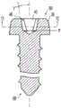
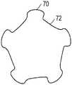
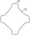
图8是紧固件的头部的顶视图。Figure 8 is a top view of the head of the fastener.
图9是穿过图8的紧固件的局部横截面图。FIG. 9 is a partial cross-sectional view through the fastener of FIG. 8 .
图10是从截面线10-10穿过图9的紧固件的横截面图。10 is a cross-sectional view through the fastener of FIG. 9 from section line 10-10.
图11是穿过图2的截面线4-4的替代横截面图。FIG. 11 is an alternate cross-sectional view through section line 4 - 4 of FIG. 2 .
图12是穿过图2的截面线4-4的另一个替代横截面图。FIG. 12 is another alternative cross-sectional view through section line 4-4 of FIG. 2 .
图13是本公开内容的替代紧固件的透视图。13 is a perspective view of an alternative fastener of the present disclosure.
图14A是图2的扭矩传送驱动器的细节图。FIG. 14A is a detail view of the torque-transmitting drive of FIG. 2 .
图14B是本公开内容的替代扭矩传送驱动器的细节图。14B is a detail view of an alternative torque-transmitting drive of the present disclosure.
图15是渐细的叶片状驱动器和紧固件系统的选择实施例的测试数据的图表。15 is a graph of test data for a selected embodiment of a tapered blade drive and fastener system.
图16图示了用于三叶片紧固件系统的驱动器的实施例。16 illustrates an embodiment of a driver for a three-blade fastener system.
图17图示了用于三叶片紧固件系统的紧固件的实施例。17 illustrates an embodiment of a fastener for a three-blade fastener system.
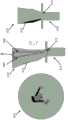
图18图示了具有离轴驱动能力的三叶片紧固件系统的实施例。18 illustrates an embodiment of a three-blade fastener system with off-axis drive capability.
图19是用于三叶片紧固件系统的驱动器的另一个实施例的端视图。19 is an end view of another embodiment of a driver for a three-blade fastener system.
图20是用于三叶片紧固件系统的驱动器的另一个实施例的端视图。图21是用于三叶片紧固件系统的驱动器的另一个实施例的端视图。图22是用于三叶片紧固件系统的驱动器的另一个实施例的端视图。20 is an end view of another embodiment of a driver for a three-blade fastener system. 21 is an end view of another embodiment of a driver for a three-blade fastener system. 22 is an end view of another embodiment of a driver for a three-blade fastener system.
具体实施方式Detailed ways
现在参照图1A至图1D,其示出了扭矩传送驱动器20的示意性图示,扭矩传送驱动器20与具有不同凹口尺寸42、44、46的多个紧固件32、34、36中具有类似形状和渐细度的对应凹口接合。诸如图1A至图1D中所示,钻头的渐细驱动表面可以包括可操作地与第一紧固件32中的第一尺寸凹口42接合的第一渐细部分52、可操作地与第二紧固件34中的第二尺寸凹口44接合的第二渐细部分54、以及可操作地与第三紧固件36中的第三尺寸凹口46接合的第三渐细部分56。如图1D中所示,在该应用中,第三紧固件36的第三尺寸凹口46比第二紧固件34的第二尺寸凹口44大,而第二紧固件34的第二尺寸凹口44比第一紧固件32的第一尺寸凹口42大。如此,扭矩传送驱动器20适于有效地驱动多于一种尺寸的紧固件。虽然图1A至图1D中所示的扭矩传送驱动器20可操作地有效接合并驱动三种不同尺寸的紧固件凹口,但扭矩传送驱动器20可以适于期望的多种紧固件凹口尺寸和紧固件尺寸。如下文所述,扭矩传送驱动器通常可以有效接合并驱动2个至4个之间的不同紧固件驱动表面(诸如,凹口或突起)。Referring now to FIGS. 1A-1D , there are shown schematic representations of a torque-transmitting
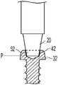
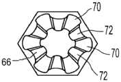
如图2中所示,扭矩传送驱动器20包括主体60,主体60具有第一端部部分62和第二端部部分64。第一端部部分62适于从扭矩发生源(诸如,动力驱动器、手动操作的驱动器柄、钻机马达或如期望的其它扭矩发生源)接收并传送扭矩。如图2和3中所示,第二端部部分64与第一端部部分62相对并且包括渐细形状的钻头66,钻头66具有围绕如图2中的A所示的旋转轴线的一系列的六个叶片70和凹槽72。如图2中所示,六个叶片70和凹槽72围绕旋转轴线对称设置,具有与旋转轴线成15°到65°之间的渐细角θ。在一个应用中,该渐细角θ为大约35°。替代地,渐细角为大约40°。在又一个应用中,渐细角是选自25°至40°之间的角。在又一个应用中,渐细角是选自45°与65°之间的角。在又一应用中,渐细角是选自45°与55°之间、50°与55°之间、或者55°与65°之间的角。在又一应用中,渐细角为大约45°或者大约52°。增大的渐细角可以为凹口提供更大的强度,从而减少紧固件和驱动器的磨损和失效。As shown in FIG. 2 , the torque-transmitting
如图3和图4中所示的扭矩传送驱动器20为六叶片驱动器。在一个替代方案中,扭矩传送驱动器20和对应的紧固件可以包括通过图11的横截面为示例示出的五叶片扭矩传送系统,或者可以是通过图12的横截面为示例示出的四叶片扭矩传送系统。在一个应用中,具有小于大约0.039英寸(1.0毫米)的主螺纹直径的小紧固件可以利用四叶片扭矩传送系统。替代地,具有小于大约0.063英寸(1.6毫米)的主螺纹直径的小紧固件可以利用四叶片扭矩传送系统。在另一个应用中,具有小于大约0.039英寸(1.0毫米)的主螺纹直径的小紧固件可以利用五叶片扭矩传送系统。在又一替代方案中,具有小于大约0.063英寸(1.6毫米)的主螺纹直径的小紧固件可以利用五叶片扭矩传送系统。The torque-transmitting
在穿过渐细钻头66的任何横截面处,诸如图4中所示的横截面,每个叶片70的最外末端形成叶片外径74,并且每个凹槽72的根部形成内径76。叶片外径74的半径和内径76的半径之间的差是叶片高度78。额外地,每个叶片具有宽度80。随着钻头66朝向第二端渐细,每个叶片具有渐细的高度和宽度。对于每个渐细叶片,随着叶片沿轴线渐细,叶片宽度与高度的比对于每个叶片是基本上相同的。At any cross-section through tapered
主体60可以是六角形柄,其具有可操作地安装在扭矩发生源中或以其他方式接合扭矩发生源(例如,动力驱动器)的长度和横截面尺寸。例如,在常规应用中,该主体可以具有5/16英寸的六角形横截面。替代地,该主体可以具有1/4六角形横截面。主体60可以具有对应于应用中所需要的扭矩发生源的所期望的任何横截面形状和尺寸。替代地,该主体可以包括插口(未示出)以用于接收扭矩发生源上的对应接合部。The
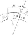
在图3至图5的示例中,在每个叶片70的至少一侧上的每个叶片70和凹槽72之间的过渡部分形成在外过渡部分半径94和内过渡部分半径96之间延伸的驱动侧过渡部分82。如图5所示,在驱动侧过渡部分82和从旋转轴线A延伸并且与内过渡部分半径96相切的径向线98之间测量驱动角α。驱动侧过渡部分82适于接合对应的紧固件表面以用于从驱动器向紧固件传递扭矩。驱动侧过渡部分的长度通常在叶片高度的大约20%至60%之间。替代地,驱动侧过渡部分的长度在叶片高度的大约10%至80%之间。在又一个替代方案中,驱动侧过渡部分的长度在叶片高度的大约20%至40%之间。如图5中所示,驱动侧过渡件82形成在0°至5°之间的驱动角α。替代地,如图6和图7中所示,在每个叶片70的至少一侧上在每个叶片和凹槽之间的过渡部分形成具有负驱动角的驱动侧过渡部分82,其中,驱动角α在0°至-10°之间。在一个应用中,驱动角α 在-2°至-10°之间。替代地,驱动角α 在-3°至-10°之间。在又一个替代方案中,驱动侧过渡部分可以形成0°至-3°之间的驱动角。当在本文中使用时,正驱动角被定义为向外成角度的驱动侧过渡部分表面,使得从该表面垂直延伸的线指向内径76的外侧或远离内径76。相反地,负驱动角被定义为向内成角的驱动侧过渡部分表面,使得从该表面垂直延伸的线指向内径76的内侧或朝向内径76。零度的驱动角提供了垂直于驱动侧过渡部分表面的线,该线平行于叶片内径和/或外径的切线。通常,紧固件驱动角与钻头驱动角大约相同以便提供表面与表面的接触。替代地,当期望时,紧固件驱动角可以大于或小于钻头驱动角以便适应紧固件与驱动器之间的间隙。In the example of FIGS. 3-5 , the transition between each
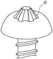
在公-母(male-female)接合中,渐细的驱动器20可操作地驱动紧固件中的对应驱动表面。在一个应用中,如上文所述和图8至图10中所示,紧固件36具有驱动端部分86和引导端部分88。驱动端部分86可操作地接合扭矩传送驱动器以及引导部分88例如通过螺纹而可操作地使紧固件紧固。驱动端部分86具有驱动表面40,驱动表面40包括围绕旋转轴线的一系列的五个或六个紧固件叶片90和紧固件凹槽92,紧固件叶片90和紧固件凹槽92具有与旋转轴线成15°至45°之间的渐细驱动表面γ。紧固件叶片90和紧固件凹槽92可操作地接合驱动器上具有类似形状和渐细度的对应的驱动表面。每个紧固件叶片90具有渐细的高度和宽度,其中,叶片的宽度与高度之比是恒定的。在紧固件凹口中,叶片90突入凹口中以便接合驱动器上的驱动器凹槽72。类似地,驱动器上的驱动器叶片70接合紧固件凹口中的紧固件凹槽92。In male-female engagement, tapered
在另一个替代方案中,例如图13中所示,紧固件驱动表面40包括四个、五个或六个叶片和凹槽的突起以便与驱动器(未示出)中的对应凹口接合。期望的是,描述对应于例如图9中所示的紧固件中的凹口的驱动器钻头的驱动表面的本申请中的讨论和参照同样适用于诸如图13中所示的紧固件上的作为突起的驱动表面。类似地,描述例如图9中所示的紧固件中的凹口的驱动表面的本申请中的讨论和参照同样适用于用于驱动诸如图13中所示的紧固件上的突起的驱动器中的凹口中的驱动表面。In another alternative, such as shown in FIG. 13 , the
叶片和凹槽渐细地进入凹口中,至少达到图9中以"P"指示的底平面。当在本文使用时,底平面P是对应的驱动器可插入凹口中的大致深度。在底平面P的下方,凹口的底部可以是锥形的、半球形的、半球体形的、平坦的或如期望的任何其它弧形或成角的形状以用于形成凹口。从底平面P开始,凹口的横截面叶片形状朝向具有渐细角γ的紧固件凹口的顶部向外渐细。凹口渐细角γ可以与驱动器渐细角θ大致相同。替代地,凹口渐细角γ可以稍微大于驱动器渐细角θ以用于制造公差。在另一个替代方案中,凹口渐细角γ可以比驱动器渐细角θ大0.5°至5°之间。作为一个示例,凹口渐细角γ可以被指定为在35°至36°之间,并且驱动器渐细角θ被指定为在34°至35°之间,其中,名义上凹口渐细角γ和驱动器渐细角θ都为35°。在另一个示例中,凹口渐细角γ可以被指定为在52°与53°之间,并且驱动器渐细角θ可以被指定为在51°与52°之间,其中,名义上凹口渐细角γ和驱动器渐细角θ都为52°。在另一个示例中,凹口渐细角γ可以被指定为在45°与46°之间,并且驱动器渐细角θ可以被指定为在44°与45°之间,其中,名义上凹口渐细角γ和驱动器渐细角θ都为45°。然而,当期望时,凹口渐细角γ和驱动器渐细角θ可以与旋转轴线成15°至65°之间的任意角。The vanes and grooves taper into the recesses, at least up to the bottom plane indicated by "P" in FIG. 9 . As used herein, the bottom plane P is the approximate depth to which the corresponding driver can be inserted into the recess. Below the bottom plane P, the bottom of the notch may be tapered, hemispherical, hemispherical, flat or any other arcuate or angled shape as desired for forming the notch. Starting from the bottom plane P, the cross-sectional blade shape of the notch tapers outwardly toward the top of the fastener notch having a tapering angle γ. The notch taper angle γ may be approximately the same as the driver taper angle θ. Alternatively, the notch taper angle γ may be slightly larger than the driver taper angle θ for manufacturing tolerances. In another alternative, the notch taper angle γ may be between 0.5° and 5° greater than the driver taper angle θ. As an example, the notch taper angle γ may be specified as between 35° and 36°, and the driver taper angle θ is specified as between 34° and 35°, where nominally the notch taper angle is Both γ and the driver taper angle θ are 35°. In another example, the notch taper angle γ may be specified as between 52° and 53°, and the driver taper angle θ may be specified as between 51° and 52°, where nominally the notch Both the taper angle γ and the driver taper angle θ are 52°. In another example, the notch taper angle γ may be specified as between 45° and 46°, and the driver taper angle θ may be specified as between 44° and 45°, where nominally the notch Both the taper angle γ and the driver taper angle θ are 45°. However, when desired, the notch taper angle γ and the driver taper angle θ may be at any angle between 15° and 65° with respect to the axis of rotation.
紧固系统可以被提供,由此一个扭矩传送驱动器20可操作地驱动多个不同尺寸的紧固件32、34、36。渐细的驱动器20可以被构造成利用相同尺寸的钻头66驱动两个或更多个不同尺寸的紧固件。在图1A至图1D的示例中,渐细钻头的末端部分具有形成第一渐细部分52的横截面尺寸,第一渐细部分52可操作地接合对应于该第一渐细部分的尺寸的紧固件。第二渐细部分54可以在渐细钻头上在位置上邻近于第一渐细部分52,第二渐细部分54具有大于第一渐细部分的横截面尺寸。第二渐细部分54可操作地接合对应于该第二渐细部分的尺寸的紧固件。类似地,第三渐细部分56邻近于第二渐细部分54,第三渐细部分56可操作地接合对应于该第三渐细部分的尺寸的紧固件。例如,一个驱动器可以适于驱动相关尺寸的6、8和10螺纹件,其中,钻头的第一渐细部分52适于#6螺纹件,第二渐细部分54适于#8螺纹件并且第三渐细部分56适于#10螺纹件。在其它替代方案中,一个驱动器可以适于驱动相关尺寸的8、10和12螺纹件,并且另一个驱动器适于驱动相关的1/4英寸、5/16英寸和3/8英寸螺纹件。替代地,驱动器可以适于驱动多个小紧固件,例如,与驱动器相关的尺寸#0和#1紧固件或更小的紧固件。当期望时,驱动器可以适于驱动两个或更多个具有相继尺寸的相关紧固件。A fastening system may be provided whereby one
对于一个驱动器20驱动具有不同尺寸的多个紧固件32、34、36,每个紧固件具有对应于驱动器的驱动表面40,使得不同尺寸的驱动表面具有在尺寸和形状上基本相同的至少一个横截面。具体地,参照图1A至图1D,对于与期望的驱动钻头20相关的每个紧固件,在底平面P处的凹口42、44、46的横截面的尺寸和形状是大致相同的。额外地,在第二端64处的驱动器20的对应横截面尺寸和形状与在底平面P处的紧固件尺寸和形状大致相同。对于某些应用,在第二端64处的驱动器20的横截面尺寸和形状小于在底平面P处的紧固件尺寸和形状,以用于易于驱动器插入凹口以及从凹口移除。替代地,在第二端64处的驱动器20的横截面尺寸和形状稍微大于在底平面P处的紧固件尺寸和形状,使得驱动器和紧固件之间的干涉使得紧固件可释放地卡住(stick)驱动器以使得组装者不必使紧固件保持在驱动器上。For one
紧固件的驱动表面和对应构造的钻头驱动表面被构造成用于紧固件驱动表面与对应的钻头驱动表面接合至足以允许从驱动器钻头至紧固件的良好扭矩施加的接合深度。例如,具有小于约0.039英寸(1.0mm)的主螺纹直径的小紧固件可以具有小于0.010英寸(0.25毫米)的驱动表面的有效接合深度。对于例如具有大于大约0.236英寸(6.0毫米)的主螺纹直径的较大的紧固件而言,该有效接合深度可以为0.06英寸(1.5毫米)或更大。The fastener driving surfaces and correspondingly configured bit driving surfaces are configured for engagement of the fastener driving surfaces with the corresponding bit driving surfaces to a depth of engagement sufficient to allow good torque application from the driver bit to the fastener. For example, a small fastener with a primary thread diameter of less than about 0.039 inches (1.0 mm) may have an effective depth of engagement of a drive surface of less than 0.010 inches (0.25 mm). For larger fasteners, eg, having a primary thread diameter greater than about 0.236 inches (6.0 mm), the effective engagement depth may be 0.06 inches (1.5 mm) or greater.
对于某些较大的紧固件应用,渐细的紧固件驱动表面和相关驱动器可以使用传统的冷锻和/或机加工技术制造。然而,较小的紧固件趋于需要提高的精度。在一个应用中,通过冲压来在紧固件上压出或模压出紧固件驱动表面。对于某些应用,例如对于具有小于大约0.039英寸(1.0毫米)的主螺纹直径或替代地具有小于大约0.063英寸(1.6毫米)的主螺纹直径的小紧固件,驱动器可以通过电火花加工(EDM)或电化学加工(ECM)来制造。可想到的是,滚铣也可用于某些适合的几何形状。For certain larger fastener applications, tapered fastener driving surfaces and associated drivers can be fabricated using conventional cold forging and/or machining techniques. However, smaller fasteners tend to require increased precision. In one application, the fastener driving surface is pressed or stamped on the fastener by stamping. For certain applications, such as for small fasteners having a main thread diameter of less than about 0.039 inches (1.0 mm) or, alternatively, a main thread diameter of less than about 0.063 inches (1.6 mm), the driver can be processed by electrical discharge machining (EDM). ) or electrochemical machining (ECM). It is contemplated that hobbing may also be used for certain suitable geometries.
对于应用,当期望时当前扭矩传送驱动器可以是钢的或铝合金的。在一个替代方案中,钢是中碳钢,例如,AISI S2, 6150, 8650, 8660或如所期望的其它工具钢组分或合金钢组分以用于可硬化性和强度。中碳钢可在制成驱动器后硬化。在扭矩传送驱动器形成后,钢驱动器可以硬化至58-62HRC的硬度。替代地,钢驱动器可以硬化至大于52HRC的硬度。For applications, current torque-transmitting drives may be steel or aluminum alloys when desired. In an alternative, the steel is a medium carbon steel, eg, AISI S2, 6150, 8650, 8660 or other tool steel components or alloy steel components as desired for hardenability and strength. Medium carbon steel can be hardened after the drive is made. After the torque transmitting drive is formed, the steel drive can be hardened to a hardness of 58-62HRC. Alternatively, the steel driver can be hardened to a hardness greater than 52HRC.
如上文所述,例如图3中所示的驱动器的叶片70随着钻头66渐细而渐细。在这些实施例中,当钻头的横截面尺寸(见图2-4)减小时,叶片70与凹槽72的比例将保持基本相同。因为叶片是渐细的,所以从紧固件对驱动器叶片所施加的反作用力(其被示意性地表示为图14A中的“FR”)包括升角β。反作用力FR包括沿驱动器轴线的分量(其被示意性地表示为图14A中的“FV”),在紧固件的驱动期间,该分量沿趋于抬升驱动器20并且减少驱动器在紧固件凹口中的接合的方向。该过程被称为“滑出”,因为当驱动时,扭矩增加并且分量FV增加,当与分量 FV相对的力没有被施加时,驱动器可能沿远离紧固件凹口的方向抬升,并且在一些情况下,驱动器可能抬升至足以与紧固件凹口脱离。As described above, the
当前公开的紧固件系统抑制滑出,并且对于某些应用可以期望进一步减小导致滑出的力。在图14B中所示的一个示例中,驱动器66'的驱动表面102可以被改进,同时后表面104可以如先前阐述的那样渐细。如图14B中所示,驱动表面102可以基本上平行于驱动器的旋转轴线,从而取决于制造公差将升角β减小至等于或接近零度。在一个替代方案中,驱动表面102上的升角可以在0°至2°之间。该升角可以被选择成以便减少当扭矩通过驱动器施加至紧固件时作用在驱动器上的竖直力的量。当扭矩需求增加时,可能期望升角等于或接近零度。在低扭矩结构中,升角可能不需要被高度约束,如由应用确定。在图14B所示的具有大约为零度的驱动侧角的结构中,当使用驱动器来使紧固件与对应的凹口紧固时,升角β将接近零,从而减少在紧固期间可能的滑出。当图14B中所示的驱动器被用于松开紧固件时,在驱动紧固件的移除的后表面104上的升角可以大于零。紧固件可以被设计成容纳单独的驱动器以用于紧固件的安装和移除,这对于防擅动(tamper-resistant)应用可能是期望的。The presently disclosed fastener system inhibits slip-out, and for certain applications it may be desirable to further reduce the forces that cause slip-out. In one example shown in Figure 14B, the
图14B中所示的驱动器66′能够实现在紧固件凹口中的叶片的对应驱动侧上的较小的渐细,这增加了紧固件的叶片中的材料的量从而使得紧固件更强。紧固件叶片中增加的材料可以导致驱动器和紧固件之间的扭矩差在量上接近,进一步协助抑制滑出并改善驱动器的维护。The driver 66' shown in Figure 14B enables a smaller taper on the corresponding drive side of the blade in the fastener recess, which increases the amount of material in the blade of the fastener thereby making the fastener more compact powerful. The increased material in the fastener blades can cause the torque difference between the driver and the fastener to be close in magnitude, further assisting in inhibiting slip-out and improving driver maintenance.
现在参照图15,对所公开的渐细的叶片状驱动器和紧固件系统进行测试。在每种情况下,使具有所选的渐细角的一组渐细的叶片状驱动钻头与相应凹口接合。如图15所示,三次测试包括:具有35°的渐细角的五叶片驱动钻头和凹口,具有45°的渐细角的六叶片驱动系统,以及具有52°的渐细角的六叶片驱动系统。分别向驱动钻头施加扭矩直到驱动系统无法识别系统的强度。另外,在标准的紧固件凹口以及在具有显著增加的强度的高速钢中形成的凹口中对驱动钻头进行测试以便单独地分析驱动钻头的强度。黑色参照线指示现有技术的市售的六叶片直壁驱动钻头的规定驱动钻头强度。如所示,具有45°和52°的渐细角的六叶片驱动钻头都超过了六叶片直壁驱动钻头的驱动钻头强度。因此,渐细的叶片状驱动器和紧固件提供了对驱动系统强度的改进并且结合在多种尺寸的紧固件的情况下使用单个驱动器的能力,同时降低了在紧固期间的滑出的可能性。Referring now to FIG. 15, the disclosed tapered blade drive and fastener system was tested. In each case, a set of tapered blade-like drive bits with selected tapering angles are brought into engagement with the corresponding recesses. As shown in Figure 15, the three tests included: a five-blade drive bit and notch with a taper angle of 35°, a six-blade drive system with a taper angle of 45°, and a six-blade drive system with a taper angle of 52° Drive System. Torque is applied to the drive bit separately until the drive system fails to recognize the strength of the system. Additionally, the drive bits were tested in standard fastener recesses as well as recesses formed in high speed steel with significantly increased strength to analyze the strength of the drive bits individually. The black reference line indicates the stated drive bit strength of a prior art commercial six-blade straight wall drive bit. As shown, both the 45° and 52° tapering six-blade drive bits exceed the drive bit strength of the six-blade straight wall drive bit. Thus, the tapered bladed driver and fasteners provide an improvement in the strength of the drive system combined with the ability to use a single driver with multiple sized fasteners, while reducing slip-out during tightening possibility.
三叶片实施例Three-blade embodiment
现在参照图16至图18,还公开了一种紧固件系统,该紧固件系统包括紧固件和具有三叶片驱动表面构造的驱动器。Referring now to FIGS. 16-18 , a fastener system is also disclosed that includes a fastener and a driver having a three-blade drive surface configuration.
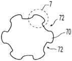
参照图16,其在多个视图中示出了驱动器210的实施例。驱动器210包括由围绕旋转轴线的一系列的三个交替的叶片214和凹槽216限定的渐细形状的钻头212。交替的叶片214和凹槽216的每一个由外半径部分220、驱动侧过渡部分222、内过渡半径224以及反向驱动部分226限定,如横截面图中清楚示出的。每个叶片214具有渐细的高度和宽度,其中,叶片宽度与叶片高度之比基本上恒定。以上面关于图5和图7描述的相同方式来测量叶片高度和宽度。外半径部分220限定给定位置处的钻头的外径,并且进一步限定驱动器的侧壁230。驱动器的侧壁230关于驱动器的旋转轴线以渐细角θ渐细。驱动器的侧壁的渐细角θ小于或等于凹口的侧壁的渐细角(如下文进一步讨论的)。Referring to Figure 16, an embodiment of the
参照图17,其图示了用于被公开的紧固件系统的紧固件310的实施例。紧固件310包括头部311和柄部313,头部311具有凹口312。柄部313可以是带螺纹的。凹口312由围绕紧固件的旋转轴线的一系列的三个交替的叶片314和凹槽316限定。交替的叶片和凹槽的每一个由外半径部分320、驱动侧过渡部分322、内过渡半径324以及反向驱动部分326限定。类似于上文讨论的驱动器,外半径部分320限定给定位置处的凹口的外径,并且进一步限定凹口的侧壁330。凹口的侧壁330关于紧固件的旋转轴线以渐细角θ渐细。在一些实施例中,凹口侧壁的渐细角为大约60°。Referring to Figure 17, an embodiment of a
现在参照图18,驱动器210和紧固件310组合以形成紧固件系统。在一些实施例中,三叶片紧固件系统提供离轴驱动能力的优点。当在本文中使用时,离轴驱动能力意指当驱动器的旋转轴线不与紧固件的旋转轴线对齐时将扭矩从驱动器传送到紧固件的能力。在一些实施例中,所公开的紧固件系统能够在紧固件和驱动器的旋转轴线相差多达20°的情况下驱动紧固件。Referring now to FIG. 18, the
在一些实施例中,驱动器侧壁230具有渐细角θ,该渐细角θ大致等于凹口侧壁330的渐细角。在一个实施例中,驱动器侧壁230的渐细角θ为大约60°。在该实施例中,驱动器和紧固件凹口的三叶片构造可以允许一些离轴驱动能力。In some embodiments, the
在其它实施例中,驱动器侧壁渐细角小于凹口侧壁渐细角。例如,驱动器侧壁渐细角可以比凹口侧壁渐细角小至少10°。在图16和图18所示的实施例中,驱动器侧壁具有大约42°的渐细角。当驱动器侧壁渐细角小于凹口侧壁渐细角时,驱动器钻头可以在凹口内倾斜,从而使得驱动器的旋转轴线400偏离紧固件的旋转轴线402。驱动器的旋转轴线400与紧固件的旋转轴线402之间的角β指示驱动器相对于紧固件的“离轴”程度。在一些实施例中,所公开的紧固件系统能够在驱动器的旋转轴线偏离紧固件的旋转轴线多达20°的情况下将扭矩传送到紧固件。这种特征有助于在产品的构造不允许同轴接近紧固件的凹口的产品中使用所公开的紧固件系统。In other embodiments, the driver sidewall taper angle is smaller than the recess sidewall taper angle. For example, the driver sidewall taper angle may be at least 10° smaller than the notch sidewall taper angle. In the embodiment shown in Figures 16 and 18, the driver sidewalls have a tapering angle of approximately 42°. When the driver sidewall taper angle is smaller than the notch sidewall taper angle, the driver bit can be tilted within the notch such that the driver's axis of
再次参照图16和图17,驱动侧过渡部分222、232可以是线性的并且限定驱动角α。驱动角α被定义为驱动侧过渡部分222与从旋转轴线延伸并且与内过渡半径224、324相切的径向线之间的角。在各个实施例中,驱动角α可以在0°至5°之间。驱动侧过渡部分222、322的长度也可以在叶片长度的20%至60%之间。在又一实施例中,驱动器210的驱动侧过渡部分222适于以小于2°的升角接合紧固件310的驱动侧过渡部分322以便减少滑出。Referring again to Figures 16 and 17, the drive side transitions 222, 232 may be linear and define a drive angle a. The drive angle α is defined as the angle between the drive-
外半径部分220、320由可以是恒定的或变化的一个或多个半径限定。内过渡半径224、324也由可以是恒定的或变化的一个或多个半径限定。在一个实施例中,内过渡半径包括由第一半径限定的第一段以及由大于第一半径的第二半径限定的第二段。反向驱动部分226、326从内过渡半径224、324延伸至外半径部分220、320,并且被构造成允许旋转紧固件以用于移除。The
驱动器210还具有位于钻头212的端部处的末端部分240。在一些实施例中,末端部分240包括三叶片驱动表面构造,然而,外过渡半径220以比钻头212中更大的渐细角渐细。在一个实施例中,外过渡半径220在末端部分240中以大约140°渐细。末端部分中的外过渡半径的增大的渐细可以改善驱动器在紧固件的凹口中的接合,特别是对于小紧固件而言,在小紧固件的情况下,对齐驱动器和紧固件凹口能够是困难的。The
如先前讨论的,紧固件系统允许一个驱动器与多个不同尺寸的紧固件一起使用。该多个紧固件的每一个可以具有由三叶片构造限定的凹口并且具有基本上相同的侧壁渐细角,使得每个紧固件的凹口的至少一个横截面与其它紧固件的凹口的一个横截面基本上相同。以此方式,单个驱动器可以用于驱动两种或更多种不同大小的紧固件,从而进一步改善了紧固系统的效率。三叶片紧固系统对于小紧固件(诸如,具有小于0.063英寸(1.6毫米)或者小于0.039英寸(1.0毫米)的主螺纹直径的那些紧固件)可能是特别有利的。As previously discussed, the fastener system allows one driver to be used with multiple fasteners of different sizes. Each of the plurality of fasteners may have a notch defined by a three-lobed configuration and have substantially the same sidewall taper angle such that at least one cross-section of the notch of each fastener is different from that of the other fasteners One cross section of the notch is substantially the same. In this way, a single driver can be used to drive two or more differently sized fasteners, further improving the efficiency of the fastening system. A three-blade fastening system may be particularly advantageous for small fasteners, such as those having a primary thread diameter of less than 0.063 inches (1.6 millimeters) or less than 0.039 inches (1.0 millimeters).
现在参照图19至图22,其图示了用于三叶片紧固件系统的驱动器的实施例。该紧固件系统还包括一个或多个紧固件(未示出),每个紧固件都具有被构造成与驱动器的构造匹配的凹口。为了清楚起见,每个驱动器被示出为具有平坦的末端部分。驱动器的一些实施例可以包括如先前讨论的渐细的末端部分。Referring now to Figures 19-22, an embodiment of a driver for a three-blade fastener system is illustrated. The fastener system also includes one or more fasteners (not shown), each fastener having a notch configured to mate with the configuration of the driver. For clarity, each driver is shown with a flat end portion. Some embodiments of the driver may include a tapered end portion as previously discussed.
现在参照图19,其图示了与图16至图18所示的驱动器类似的驱动器500。驱动器500具有三个交替的叶片和凹槽。为了比较,驱动器500被示出为覆盖有图2至图3所示的驱动器的六叶片构造。在该实施例中,三叶片驱动器的驱动侧过渡部分与六叶片构造的驱动侧过渡部分对齐。外半径部分和反向驱动部分防止在六叶片构造的紧固件中使用三叶片驱动器。Referring now to Figure 19, a
现在参照图20,其图示了每个叶片的宽度以更大角度沿着驱动器的长度向上移动而增加的驱动器600。增加的叶片宽度可以为驱动钻头提供额外强度。在一些实施例中,叶片的宽度增加的角度可以与驱动器侧壁的渐细角有关。在一个示例中,驱动器可以具有减小的侧壁渐细角并且包括更大的用于增加叶片宽度的角度。以此方式,驱动器可以容纳一系列浅凹口紧固件。Referring now to FIG. 20, a
现在参照图21,其公开了用于三叶片紧固件系统的驱动器700的又一实施例。驱动器700包括三个交替的叶片和凹槽,如上文通常描述的,该三个交替的叶片和凹槽由外半径部分720、驱动侧过渡部分722、内过渡半径724以及反向驱动部分限定。反向驱动部分由凹形部分726'和捕获(catch)部分726''限定。凹形部分726'是由来自驱动器的外径外的原点的恒定半径或者变化半径限定的弯曲部分。捕获部分726''通常径向地延伸。在一个实施例中,捕获部分726''限定大致45°的反向驱动角。驱动器700的反向驱动部分可以提供高进的移除紧固件的能力,这对于设想移除紧固件的应用可能是有利的。紧固件系统还包括一个或多个紧固件(未示出),每个紧固件具有被构造成与驱动器700的构造匹配的凹口。Referring now to FIG. 21, yet another embodiment of a
现在参照图22,其公开了用于三叶片紧固件系统的驱动器800的又一实施例。驱动器800包括三个交替的叶片和凹槽,如上文通常描述的,该三个交替的叶片和凹槽由外半径部分、驱动侧过渡部分722、内过渡半径724以及反向驱动部分限定。驱动器800的反向驱动部分可以包括与驱动器700的构造类似的凹形部分826'和捕获部分826''。驱动器800的外半径部分可以包括被构造成改善紧固件系统的功能的两段或多段。例如,该构造可以改善向前驱动能力、反向驱动能力、离轴驱动能力、驱动器在紧固件凹口中的安置或接合、或者紧固件系统的类似功能。在一个实施例中,驱动器800的外半径部分包括第一凸形段820'、凹形段820''和第二凸形段822'''。外过渡半径的至少一部分限定驱动器800的侧壁,并且以如上文讨论的渐细角渐细。Referring now to FIG. 22, yet another embodiment of a
本文中公开的驱动器和紧固件可以组合使用以便形成紧固系统,只要驱动器钻头和紧固件凹口的构造与驱动器的插入和移除兼容,并且与将扭矩施加到紧固件兼容。在一个示例中,与图21所示的驱动器800相对应的紧固件可以与图19所示的驱动器500安装在一起。基于构造的兼容性,也能设想紧固件和驱动器的其它组合。The drivers and fasteners disclosed herein can be used in combination to form a fastening system, so long as the configuration of the driver bit and fastener recess is compatible with insertion and removal of the driver and with the application of torque to the fastener. In one example, fasteners corresponding to the
虽然已经在附图和前面的描述中详细说明并描述了本发明,但是本发明应该被认为在特性上是说明性的而不是限制性的,要理解的是,仅示出并描述了优选实施例,并且落入本发明的精神范围内的所有改变和改进都期望受到所附权利要求书及其等同物的保护。While the present invention has been illustrated and described in detail in the accompanying drawings and the foregoing description, the present invention is to be considered illustrative in nature and not restrictive, it being understood that only preferred embodiments have been shown and described. example, and all changes and modifications falling within the spirit of the invention are intended to be protected by the appended claims and their equivalents.
Claims (14)
Translated fromChinesePriority Applications (1)
| Application Number | Priority Date | Filing Date | Title |
|---|---|---|---|
| CN202010811695.7ACN111941336B (en) | 2015-08-18 | 2016-08-18 | Tapered blade driver and fastener |
Applications Claiming Priority (3)
| Application Number | Priority Date | Filing Date | Title |
|---|---|---|---|
| US201562206555P | 2015-08-18 | 2015-08-18 | |
| US62/206555 | 2015-08-18 | ||
| PCT/US2016/047582WO2017031333A1 (en) | 2015-08-18 | 2016-08-18 | Tapered lobular driver and fastener |
Related Child Applications (1)
| Application Number | Title | Priority Date | Filing Date |
|---|---|---|---|
| CN202010811695.7ADivisionCN111941336B (en) | 2015-08-18 | 2016-08-18 | Tapered blade driver and fastener |
Publications (2)
| Publication Number | Publication Date |
|---|---|
| CN107921612A CN107921612A (en) | 2018-04-17 |
| CN107921612Btrue CN107921612B (en) | 2020-08-14 |
Family
ID=58052016
Family Applications (2)
| Application Number | Title | Priority Date | Filing Date |
|---|---|---|---|
| CN201680048353.6AActiveCN107921612B (en) | 2015-08-18 | 2016-08-18 | Tapered blade driver and fastener |
| CN202010811695.7AActiveCN111941336B (en) | 2015-08-18 | 2016-08-18 | Tapered blade driver and fastener |
Family Applications After (1)
| Application Number | Title | Priority Date | Filing Date |
|---|---|---|---|
| CN202010811695.7AActiveCN111941336B (en) | 2015-08-18 | 2016-08-18 | Tapered blade driver and fastener |
Country Status (13)
| Country | Link |
|---|---|
| US (2) | US10195723B2 (en) |
| EP (2) | EP3337644B1 (en) |
| JP (2) | JP6996815B2 (en) |
| KR (1) | KR102499407B1 (en) |
| CN (2) | CN107921612B (en) |
| AU (2) | AU2016308839B2 (en) |
| BR (1) | BR112018002931B1 (en) |
| CA (1) | CA2993668C (en) |
| IL (1) | IL257099B (en) |
| MX (2) | MX2018001679A (en) |
| MY (1) | MY191432A (en) |
| WO (1) | WO2017031333A1 (en) |
| ZA (2) | ZA201800750B (en) |
Families Citing this family (15)
| Publication number | Priority date | Publication date | Assignee | Title |
|---|---|---|---|---|
| US20180106286A1 (en)* | 2016-10-17 | 2018-04-19 | Consolidated Fasteners Inc | Driver/Fastener Inter-engagement System |
| US10690168B2 (en) | 2017-04-14 | 2020-06-23 | Maclean-Fogg Company | Three-point fastener |
| USD889257S1 (en) | 2017-05-22 | 2020-07-07 | Grip Holdings Llc | Anti-slip multidirectional driver bit |
| US11028870B2 (en) | 2018-01-16 | 2021-06-08 | Maclean-Fogg Company | Hybrid three-point drive fastener |
| USD892604S1 (en)* | 2018-11-08 | 2020-08-11 | Superior Tool Co., Ltd. | Screw |
| EP3914832A4 (en)* | 2019-01-24 | 2022-12-07 | Acument Intellectual Properties LLC | IMPROVED STICK-FIT BIT DESIGN |
| US11926021B2 (en)* | 2019-02-26 | 2024-03-12 | Ttapdrive As | Drive system configured to provide frictional fit engagement |
| WO2020214525A1 (en) | 2019-04-18 | 2020-10-22 | Sheh Fung Screws Co., Ltd. | Fastener having improved wobble control, fastening system including the same, and method of forming the same |
| JP1657097S (en)* | 2019-07-25 | 2020-04-13 | ||
| US20210246928A1 (en)* | 2020-02-11 | 2021-08-12 | Carl Chasse | Fastener having improved wobble control, fastening system including the same, and method of forming the same |
| WO2022200920A1 (en) | 2021-03-23 | 2022-09-29 | Ricoh Company, Ltd. | Curved surface resin structure, electronic light control lens, and method for producing curved surface resin structure |
| CN113803342A (en)* | 2021-10-14 | 2021-12-17 | 东方蓝天钛金科技有限公司 | Fastener and installation screwdriver matched with same |
| USD1033446S1 (en) | 2021-10-27 | 2024-07-02 | Samsung Electronics Co., Ltd. | Display screen or portion thereof with transitional graphical user interface |
| TWI782770B (en)* | 2021-10-28 | 2022-11-01 | 寬仕工業股份有限公司 | Fasteners, driver bits and forming punches |
| USD1075835S1 (en) | 2023-02-08 | 2025-05-20 | Samsung Electronics Co., Ltd. | Display screen or portion thereof with transitional graphical user interface |
Family Cites Families (27)
| Publication number | Priority date | Publication date | Assignee | Title |
|---|---|---|---|---|
| NL42923C (en) | 1934-07-03 | |||
| US2397216A (en) | 1944-06-16 | 1946-03-26 | Domnic V Stellin | Socket head screw |
| US2556155A (en)* | 1946-07-13 | 1951-06-05 | Domnic V Stellin | Socket head screw |
| US2969250A (en) | 1959-01-05 | 1961-01-24 | Standard Pressed Steel Co | Socket drive |
| US3187790A (en) | 1959-05-18 | 1965-06-08 | Hi Shear Rivet Tool Company | Screw and screw driver coupling |
| US3213719A (en)* | 1962-11-01 | 1965-10-26 | Robert C Kloack | Rotary driving tool with universal action |
| US3584667A (en) | 1966-09-19 | 1971-06-15 | Textron Inc | Coupling arrangement and tools for same |
| US4084478A (en) | 1974-09-12 | 1978-04-18 | Phillips Screw Company | Screw heads |
| US4246811A (en)* | 1979-09-24 | 1981-01-27 | Bondhus Corporation | Ball head polygonal wrench |
| EP0046010B1 (en)* | 1980-07-23 | 1986-04-09 | European Industrial Services (Fasteners) Limited | Fastener and driver combination |
| US4970922A (en)* | 1989-03-23 | 1990-11-20 | Snap-On Tools Corporation | Torque driving tool and retainer for driven member |
| US5207132A (en) | 1991-10-16 | 1993-05-04 | Textron Inc. | Elliptical lobed drive system |
| US5370021A (en)* | 1993-05-13 | 1994-12-06 | Eight Co., Ltd. | Polygon headed wrench |
| US5598753A (en)* | 1995-02-07 | 1997-02-04 | Lee; James S. | Eagle wing tips tamper-proof fastener and driver tool |
| US5957645A (en)* | 1997-10-31 | 1999-09-28 | Phillips Screw Company | Spiral drive system for threaded fasteners |
| JP4493135B2 (en)* | 2000-01-06 | 2010-06-30 | 勝行 戸津 | Screw and driver bit combination |
| DE60236463D1 (en)* | 2002-05-27 | 2010-07-01 | Osg Corp | Structure for twisting a threaded element |
| JP4031418B2 (en)* | 2003-09-12 | 2008-01-09 | 株式会社スズキ螺子製作所 | Screw and screw driver |
| EP1693577B1 (en)* | 2003-11-14 | 2016-03-23 | Katsuyuki Totsu | Screw with stabilized strength, combination with driver bit, and header punch for producing screw with stabilized strength |
| US7293949B2 (en) | 2004-04-15 | 2007-11-13 | Phillips Screw Company | Spiral drive fastener with friction engageable surface |
| US7690282B2 (en)* | 2005-08-03 | 2010-04-06 | Synthes Usa, Llc | Screw-retaining screwdriver |
| US8182187B2 (en)* | 2008-04-21 | 2012-05-22 | Asia Fastening (Us), Inc. | Drive system |
| US20110048181A1 (en)* | 2009-08-27 | 2011-03-03 | Hama Naka Shoukin Industry Co., Ltd. | Screw head recess structure and its driving tool |
| US8291795B2 (en) | 2010-03-02 | 2012-10-23 | Phillips Screw Company | Fastener system with stable engagement and stick fit |
| US10968939B2 (en)* | 2011-08-25 | 2021-04-06 | Infastech Intellectual Properties Pte. Ltd. | Tapered lobular driver and fastener |
| CA2846336C (en)* | 2011-08-25 | 2021-02-23 | Infastech Intellectual Properties Pte. Ltd. | Tapered lobular driver and fastener |
| EP3493691A4 (en)* | 2016-08-05 | 2020-04-08 | Romello Burdoucci | DEVICE, SYSTEM AND METHOD FOR INTELLIGENT INTERACTIVE AND AUTONOMOUS ROBOTIC LAND MAINTENANCE |
- 2016
- 2016-08-18EPEP16837848.7Apatent/EP3337644B1/enactiveActive
- 2016-08-18CACA2993668Apatent/CA2993668C/enactiveActive
- 2016-08-18JPJP2018503796Apatent/JP6996815B2/enactiveActive
- 2016-08-18WOPCT/US2016/047582patent/WO2017031333A1/ennot_activeCeased
- 2016-08-18AUAU2016308839Apatent/AU2016308839B2/enactiveActive
- 2016-08-18CNCN201680048353.6Apatent/CN107921612B/enactiveActive
- 2016-08-18MYMYPI2018000125Apatent/MY191432A/enunknown
- 2016-08-18CNCN202010811695.7Apatent/CN111941336B/enactiveActive
- 2016-08-18KRKR1020187004277Apatent/KR102499407B1/enactiveActive
- 2016-08-18EPEP20214628.8Apatent/EP3822026B1/enactiveActive
- 2016-08-18USUS15/240,690patent/US10195723B2/enactiveActive
- 2016-08-18BRBR112018002931-9Apatent/BR112018002931B1/enactiveIP Right Grant
- 2016-08-18MXMX2018001679Apatent/MX2018001679A/enunknown
- 2018
- 2018-01-23ILIL257099Apatent/IL257099B/enunknown
- 2018-02-05ZAZA201800750Apatent/ZA201800750B/enunknown
- 2018-02-08MXMX2022004606Apatent/MX2022004606A/enunknown
- 2018-12-20USUS16/227,329patent/US11364601B2/enactiveActive
- 2019
- 2019-06-06ZAZA2019/03622Apatent/ZA201903622B/enunknown
- 2021
- 2021-08-31AUAU2021225170Apatent/AU2021225170B2/enactiveActive
- 2021-12-13JPJP2021201691Apatent/JP7485257B2/enactiveActive
Also Published As
| Publication number | Publication date |
|---|---|
| IL257099B (en) | 2021-10-31 |
| US11364601B2 (en) | 2022-06-21 |
| JP7485257B2 (en) | 2024-05-16 |
| US20200206882A1 (en) | 2020-07-02 |
| ZA201800750B (en) | 2019-10-30 |
| EP3337644B1 (en) | 2021-01-27 |
| EP3822026B1 (en) | 2024-10-02 |
| JP2018530439A (en) | 2018-10-18 |
| KR102499407B1 (en) | 2023-02-14 |
| KR20180041669A (en) | 2018-04-24 |
| CN111941336B (en) | 2022-07-08 |
| US20170050300A1 (en) | 2017-02-23 |
| CN111941336A (en) | 2020-11-17 |
| EP3337644A4 (en) | 2019-04-17 |
| BR112018002931B1 (en) | 2022-05-10 |
| CN107921612A (en) | 2018-04-17 |
| EP3822026A1 (en) | 2021-05-19 |
| MX2018001679A (en) | 2018-05-23 |
| BR112018002931A2 (en) | 2018-10-02 |
| WO2017031333A1 (en) | 2017-02-23 |
| CA2993668A1 (en) | 2017-02-23 |
| AU2016308839A1 (en) | 2018-03-01 |
| AU2021225170A1 (en) | 2021-09-30 |
| EP3337644A1 (en) | 2018-06-27 |
| AU2016308839B2 (en) | 2021-07-01 |
| JP2022037088A (en) | 2022-03-08 |
| MX2022004606A (en) | 2022-05-26 |
| JP6996815B2 (en) | 2022-01-17 |
| CA2993668C (en) | 2023-12-19 |
| ZA201903622B (en) | 2021-01-27 |
| MY191432A (en) | 2022-06-27 |
| IL257099A (en) | 2018-03-29 |
| AU2021225170B2 (en) | 2023-03-09 |
| US10195723B2 (en) | 2019-02-05 |
Similar Documents
| Publication | Publication Date | Title |
|---|---|---|
| CN107921612B (en) | Tapered blade driver and fastener | |
| CN104039509B (en) | Conical Blade Drivers and Fasteners | |
| CN107000176B (en) | Tapered lobed driver and fastener | |
| US10968939B2 (en) | Tapered lobular driver and fastener |
Legal Events
| Date | Code | Title | Description |
|---|---|---|---|
| PB01 | Publication | ||
| PB01 | Publication | ||
| SE01 | Entry into force of request for substantive examination | ||
| SE01 | Entry into force of request for substantive examination | ||
| GR01 | Patent grant | ||
| GR01 | Patent grant |