CN107920405B - Handheld devices capable of interacting with lighting fixtures - Google Patents
Handheld devices capable of interacting with lighting fixturesDownload PDFInfo
- Publication number
- CN107920405B CN107920405BCN201711258347.6ACN201711258347ACN107920405BCN 107920405 BCN107920405 BCN 107920405BCN 201711258347 ACN201711258347 ACN 201711258347ACN 107920405 BCN107920405 BCN 107920405B
- Authority
- CN
- China
- Prior art keywords
- lighting
- lighting fixture
- lighting fixtures
- light
- module
- Prior art date
- Legal status (The legal status is an assumption and is not a legal conclusion. Google has not performed a legal analysis and makes no representation as to the accuracy of the status listed.)
- Active
Links
Images


Classifications
- H—ELECTRICITY
- H05—ELECTRIC TECHNIQUES NOT OTHERWISE PROVIDED FOR
- H05B—ELECTRIC HEATING; ELECTRIC LIGHT SOURCES NOT OTHERWISE PROVIDED FOR; CIRCUIT ARRANGEMENTS FOR ELECTRIC LIGHT SOURCES, IN GENERAL
- H05B47/00—Circuit arrangements for operating light sources in general, i.e. where the type of light source is not relevant
- H05B47/10—Controlling the light source
- H05B47/105—Controlling the light source in response to determined parameters
- H05B47/11—Controlling the light source in response to determined parameters by determining the brightness or colour temperature of ambient light
- H—ELECTRICITY
- H05—ELECTRIC TECHNIQUES NOT OTHERWISE PROVIDED FOR
- H05B—ELECTRIC HEATING; ELECTRIC LIGHT SOURCES NOT OTHERWISE PROVIDED FOR; CIRCUIT ARRANGEMENTS FOR ELECTRIC LIGHT SOURCES, IN GENERAL
- H05B47/00—Circuit arrangements for operating light sources in general, i.e. where the type of light source is not relevant
- H05B47/10—Controlling the light source
- H05B47/165—Controlling the light source following a pre-assigned programmed sequence; Logic control [LC]
- H—ELECTRICITY
- H05—ELECTRIC TECHNIQUES NOT OTHERWISE PROVIDED FOR
- H05B—ELECTRIC HEATING; ELECTRIC LIGHT SOURCES NOT OTHERWISE PROVIDED FOR; CIRCUIT ARRANGEMENTS FOR ELECTRIC LIGHT SOURCES, IN GENERAL
- H05B47/00—Circuit arrangements for operating light sources in general, i.e. where the type of light source is not relevant
- H05B47/10—Controlling the light source
- H05B47/175—Controlling the light source by remote control
- H05B47/19—Controlling the light source by remote control via wireless transmission
- H—ELECTRICITY
- H05—ELECTRIC TECHNIQUES NOT OTHERWISE PROVIDED FOR
- H05B—ELECTRIC HEATING; ELECTRIC LIGHT SOURCES NOT OTHERWISE PROVIDED FOR; CIRCUIT ARRANGEMENTS FOR ELECTRIC LIGHT SOURCES, IN GENERAL
- H05B47/00—Circuit arrangements for operating light sources in general, i.e. where the type of light source is not relevant
- H05B47/10—Controlling the light source
- H05B47/175—Controlling the light source by remote control
- H05B47/196—Controlling the light source by remote control characterised by user interface arrangements
- H05B47/1965—Controlling the light source by remote control characterised by user interface arrangements using handheld communication devices
- H—ELECTRICITY
- H05—ELECTRIC TECHNIQUES NOT OTHERWISE PROVIDED FOR
- H05B—ELECTRIC HEATING; ELECTRIC LIGHT SOURCES NOT OTHERWISE PROVIDED FOR; CIRCUIT ARRANGEMENTS FOR ELECTRIC LIGHT SOURCES, IN GENERAL
- H05B47/00—Circuit arrangements for operating light sources in general, i.e. where the type of light source is not relevant
- H05B47/10—Controlling the light source
- H05B47/175—Controlling the light source by remote control
- H05B47/198—Grouping of control procedures or address assignation to light sources
- H05B47/199—Commissioning of light sources
- H—ELECTRICITY
- H05—ELECTRIC TECHNIQUES NOT OTHERWISE PROVIDED FOR
- H05B—ELECTRIC HEATING; ELECTRIC LIGHT SOURCES NOT OTHERWISE PROVIDED FOR; CIRCUIT ARRANGEMENTS FOR ELECTRIC LIGHT SOURCES, IN GENERAL
- H05B45/00—Circuit arrangements for operating light-emitting diodes [LED]
- H05B45/30—Driver circuits
- H05B45/32—Pulse-control circuits
- H05B45/325—Pulse-width modulation [PWM]
- H—ELECTRICITY
- H05—ELECTRIC TECHNIQUES NOT OTHERWISE PROVIDED FOR
- H05B—ELECTRIC HEATING; ELECTRIC LIGHT SOURCES NOT OTHERWISE PROVIDED FOR; CIRCUIT ARRANGEMENTS FOR ELECTRIC LIGHT SOURCES, IN GENERAL
- H05B45/00—Circuit arrangements for operating light-emitting diodes [LED]
- H05B45/30—Driver circuits
- H05B45/37—Converter circuits
- H05B45/3725—Switched mode power supply [SMPS]
- H—ELECTRICITY
- H05—ELECTRIC TECHNIQUES NOT OTHERWISE PROVIDED FOR
- H05B—ELECTRIC HEATING; ELECTRIC LIGHT SOURCES NOT OTHERWISE PROVIDED FOR; CIRCUIT ARRANGEMENTS FOR ELECTRIC LIGHT SOURCES, IN GENERAL
- H05B47/00—Circuit arrangements for operating light sources in general, i.e. where the type of light source is not relevant
- H05B47/10—Controlling the light source
- H05B47/175—Controlling the light source by remote control
- H05B47/19—Controlling the light source by remote control via wireless transmission
- H05B47/195—Controlling the light source by remote control via wireless transmission the transmission using visible or infrared light
- H—ELECTRICITY
- H05—ELECTRIC TECHNIQUES NOT OTHERWISE PROVIDED FOR
- H05B—ELECTRIC HEATING; ELECTRIC LIGHT SOURCES NOT OTHERWISE PROVIDED FOR; CIRCUIT ARRANGEMENTS FOR ELECTRIC LIGHT SOURCES, IN GENERAL
- H05B47/00—Circuit arrangements for operating light sources in general, i.e. where the type of light source is not relevant
- H05B47/10—Controlling the light source
- H05B47/175—Controlling the light source by remote control
- H05B47/198—Grouping of control procedures or address assignation to light sources
- H05B47/1985—Creation of lighting zones or scenes
- Y—GENERAL TAGGING OF NEW TECHNOLOGICAL DEVELOPMENTS; GENERAL TAGGING OF CROSS-SECTIONAL TECHNOLOGIES SPANNING OVER SEVERAL SECTIONS OF THE IPC; TECHNICAL SUBJECTS COVERED BY FORMER USPC CROSS-REFERENCE ART COLLECTIONS [XRACs] AND DIGESTS
- Y02—TECHNOLOGIES OR APPLICATIONS FOR MITIGATION OR ADAPTATION AGAINST CLIMATE CHANGE
- Y02B—CLIMATE CHANGE MITIGATION TECHNOLOGIES RELATED TO BUILDINGS, e.g. HOUSING, HOUSE APPLIANCES OR RELATED END-USER APPLICATIONS
- Y02B20/00—Energy efficient lighting technologies, e.g. halogen lamps or gas discharge lamps
- Y02B20/40—Control techniques providing energy savings, e.g. smart controller or presence detection
Landscapes
- Engineering & Computer Science (AREA)
- Computer Networks & Wireless Communication (AREA)
- Circuit Arrangement For Electric Light Sources In General (AREA)
Abstract
Translated fromChinese
Description
Translated fromChinese本案为分案申请。其母案的发明名称为“能够与照明器材交互的手持设备”,申请日为2015年1月2日,申请号为201580012209.2。This case is a divisional application. The name of the invention of the parent case is "hand-held device capable of interacting with lighting equipment", the application date is January 2, 2015, and the application number is 201580012209.2.
技术领域technical field
本公开涉及能够与照明器材交互的手持设备。The present disclosure relates to handheld devices capable of interacting with lighting fixtures.
背景技术Background technique
近年来,已获得吸引力的动作是用采用更高效照明技术的照明器材来取代白炽光灯泡以及用产生更合意的自然光的照明技术来取代相对高效的荧光照明器材。示出巨大前途的一种这样的技术采用发光二极管(LED)。与白炽灯泡相比,基于LED的灯器材在将电能转换成光方面高效得多,持续得更长久,并且还能够产生非常自然的光。与荧光照明相比,基于LED的器材还非常高效,但是能够产生自然得多的光,并且更能够准确地呈现颜色。结果,采用LED技术的照明器材被预期在住宅、商业和工业应用中取代白炽和荧光灯泡。In recent years, there has been an attractive move to replace incandescent light bulbs with lighting fixtures that employ more efficient lighting technologies and to replace relatively efficient fluorescent lighting fixtures with lighting technologies that produce more desirable natural light. One such technology that shows great promise employs light emitting diodes (LEDs). Compared to incandescent light bulbs, LED-based light fixtures are much more efficient at converting electrical energy into light, last longer, and also produce very natural light. Compared to fluorescent lighting, LED-based fixtures are also very efficient, but produce much more natural light and render colors more accurately. As a result, lighting fixtures employing LED technology are expected to replace incandescent and fluorescent light bulbs in residential, commercial, and industrial applications.
不像通过使灯丝经受期望的电流而操作的白炽灯泡,基于LED的照明器材需要电子器件来驱动一个或多个LED。电子器件通常包括功率供应和特殊的控制电路,以提供以期望的方式驱动一个或多个LED所需的唯一配置的信号。控制电路的存在将潜在显著水平的智能添加到照明器材,其可以被利用来采用各种类型的照明控制。Unlike incandescent light bulbs, which operate by subjecting the filament to the desired current, LED-based lighting fixtures require electronics to drive one or more LEDs. The electronics typically include power supplies and special control circuits to provide the uniquely configured signals needed to drive one or more LEDs in a desired manner. The presence of control circuitry adds a potentially significant level of intelligence to lighting fixtures, which can be exploited to employ various types of lighting controls.
用于传统的或基于LED的照明器材的照明控制系统通常采用中央控制器来控制一组照明器材。中央控制器被配置成向该组中的每个照明器材发送命令或信号,并且照明器材将对命令或信号进行响应以开启或关断、调光到期望的水平,等等。这样,由中央控制器基于由中央控制器接收的输入而做出照明控制决定,并且响应于这些照明控制决定而简单地控制照明器材。Lighting control systems for conventional or LED-based lighting fixtures typically employ a central controller to control a group of lighting fixtures. The central controller is configured to send commands or signals to each lighting fixture in the group, and the lighting fixtures will respond to the commands or signals to turn on or off, dim to a desired level, and so on. In this way, lighting control decisions are made by the central controller based on inputs received by the central controller, and lighting fixtures are simply controlled in response to these lighting control decisions.
发明内容SUMMARY OF THE INVENTION
描述了一种手持设备,其具有光源、通信接口以及控制电路。A handheld device is described that has a light source, a communication interface, and a control circuit.
在一个实施例中,电路被适配成经由光源提供光信号并经由通信接口从多个照明器材接收光水平信息,其中用于给定照明器材的光水平信息与在给定照明器材处以其接收光信号的光水平有关。电路还被适配成基于光水平信息来选择所选照明器材。电路还可以经由通信接口发送旨在指令多个照明器材开始针对光信号进行监测的指令。In one embodiment, the circuit is adapted to provide a light signal via a light source and receive light level information from a plurality of lighting fixtures via a communication interface, wherein the light level information for a given lighting fixture is the same as the light level information received therefrom at the given lighting fixture The light level of the light signal is related. The circuit is further adapted to select the selected lighting fixture based on the light level information. The circuit may also send instructions via the communication interface directed to instructing the plurality of lighting fixtures to begin monitoring for the light signal.
在另一实施例中,电路被适配成:经由光源提供光信号;从接收到光信号的照明器材接收信息;以及基于接收到信息,选择照明器材作为所选照明器材。所述信息可以包括用于所选照明器材的标识符。所述标识符可以是地址。In another embodiment, the circuit is adapted to: provide the light signal via the light source; receive information from the lighting fixture that received the light signal; and select the lighting fixture as the selected lighting fixture based on the received information. The information may include an identifier for the selected lighting fixture. The identifier may be an address.
本领域技术人员将在与附图相关联地阅读以下详细描述之后领会本公开的范围并且认识到其附加的方面。Those skilled in the art will appreciate the scope of the present disclosure and realize additional aspects thereof after reading the following detailed description in conjunction with the accompanying drawings.
附图说明Description of drawings
被并入本说明书中并形成本说明书的一部分的附图图示本公开的若干方面,并且连同描述一起用来解释公开的原理。The accompanying drawings, which are incorporated in and form a part of this specification, illustrate several aspects of the disclosure, and together with the description serve to explain the principles of the disclosure.
图1是根据本公开的一个实施例的基于灯槽的照明器材的透视图。1 is a perspective view of a light trough-based lighting fixture according to one embodiment of the present disclosure.
图2是图1的照明器材的横截面。FIG. 2 is a cross-section of the lighting fixture of FIG. 1 .
图3是图1的照明器材的横截面,图示了光如何从照明器材的LED发出并且通过照明器材的透镜而被反射出。3 is a cross-section of the lighting fixture of FIG. 1 illustrating how light is emitted from LEDs of the lighting fixture and reflected out through the lenses of the lighting fixture.
图4图示集成在图1的照明器材的电子器件外壳内的驱动器模块和通信模块。FIG. 4 illustrates a driver module and a communication module integrated within the electronics housing of the lighting fixture of FIG. 1 .
图5图示根据本公开的一个实施例的被提供在图1的照明器材的电子器件外壳中的驱动器模块和在耦合到电子器件外壳的外部的相关联的外壳中的通信模块。5 illustrates a driver module provided in an electronics housing of the lighting fixture of FIG. 1 and a communication module in an associated housing coupled to the exterior of the electronics housing, according to one embodiment of the present disclosure.
图6图示用于示例性楼层平面的照明系统。Figure 6 illustrates a lighting system for an exemplary floor plan.
图7是图示用于图6中图示的照明系统的光投射(lightcast)数据的表。FIG. 7 is a table illustrating lightcast data for the lighting system illustrated in FIG. 6 .
图8A-8E图示当为光投射过程提供从每个房间到走廊中的门开着时用于图6中图示的楼层平面的示例性的区。8A-8E illustrate exemplary zones for the floor plan illustrated in FIG. 6 when the doors from each room into the hallway are open for the light projection process.
图9是根据本公开的一个实施例的图示了分组过程的通信流程图。9 is a communication flow diagram illustrating a grouping process according to one embodiment of the present disclosure.
图10是图示在照明系统的照明器材之间共享传感器数据的通信流程图。10 is a communication flow diagram illustrating the sharing of sensor data between lighting fixtures of a lighting system.
图11是图示照明系统内的传感器数据的共享和指令的创建的通信流程图。11 is a communication flow diagram illustrating the sharing of sensor data and the creation of instructions within a lighting system.
图12是图示照明系统内指令的中继和修改指令的能力二者的通信流程图。12 is a communication flow diagram illustrating both the relaying of instructions within the lighting system and the ability to modify the instructions.
图13A图示具有三个不同区的照明系统,其中基于环境光的存在,每个区可以具有不同的输出水平。Figure 13A illustrates a lighting system with three different zones, where each zone can have a different output level based on the presence of ambient light.
图13B图示其中基于环境光的存在而在光输出中存在梯度的照明系统。13B illustrates a lighting system in which there is a gradient in light output based on the presence of ambient light.
图14是根据本公开的一个实施例的照明系统的框图。14 is a block diagram of a lighting system according to one embodiment of the present disclosure.
图15是根据本公开的第一实施例的示例性的LED的横截面。15 is a cross-section of an exemplary LED according to the first embodiment of the present disclosure.
图16是根据本公开的第二实施例的示例性的LED的横截面。16 is a cross-section of an exemplary LED according to a second embodiment of the present disclosure.
图17是根据本公开的一个实施例的驱动器模块和LED阵列的示意图。17 is a schematic diagram of a driver module and LED array according to one embodiment of the present disclosure.
图18是根据本公开的一个实施例的通信模块的框图。18 is a block diagram of a communication module according to one embodiment of the present disclosure.
图19是根据本公开的第一实施例的照明器材的框图。19 is a block diagram of a lighting fixture according to the first embodiment of the present disclosure.
图20是根据本公开的第二实施例的照明器材的框图。20 is a block diagram of a lighting fixture according to a second embodiment of the present disclosure.
图21是其中集成了驱动器模块和通信模块的功能性的照明系统的框图。21 is a block diagram of a lighting system in which the functionality of a driver module and a communication module are integrated.
图22是根据本公开的一个实施例的独立传感器模块的框图。22 is a block diagram of a stand-alone sensor module according to one embodiment of the present disclosure.
图23是根据本公开的一个实施例的调试(commissioning)工具的框图。23 is a block diagram of a commissioning tool according to one embodiment of the present disclosure.
图24是根据本公开的一个实施例的开关模块的框图。24 is a block diagram of a switch module according to one embodiment of the present disclosure.
图25是根据本公开的一个实施例的智能器材的框图。25 is a block diagram of a smart appliance according to one embodiment of the present disclosure.
图26是室内RF通信模块的框图。Figure 26 is a block diagram of an indoor RF communication module.
图27图示根据本公开的一个实施例的室外RF通信模块。27 illustrates an outdoor RF communication module according to one embodiment of the present disclosure.
图28是根据本公开的一个实施例的包括智能器材和室内RF通信模块的照明器材的框图。28 is a block diagram of a lighting fixture including a smart fixture and an indoor RF communication module, according to one embodiment of the present disclosure.
图29是根据本公开的一个实施例的包括智能器材、室内RF通信模块和器材传感器模块的照明器材的框图。29 is a block diagram of a lighting fixture including a smart fixture, an indoor RF communication module, and a fixture sensor module, according to one embodiment of the present disclosure.
图30是根据本公开的一个实施例的无线传感器的框图。30 is a block diagram of a wireless sensor according to one embodiment of the present disclosure.
图31是根据本公开的一个实施例的能够驱动遗留(legacy)器材的无线中继模块的框图。31 is a block diagram of a wireless relay module capable of driving legacy equipment, according to one embodiment of the present disclosure.
图32是根据本公开的一个实施例的无线开关的框图。32 is a block diagram of a wireless switch according to one embodiment of the present disclosure.
图33是根据本公开的一个实施例的图示用于选择协调器的迭代过程的通信流程图。33 is a communication flow diagram illustrating an iterative process for selecting a coordinator, according to one embodiment of the present disclosure.
图34是根据本公开的另一个实施例的图示用于选择协调器的迭代过程的通信流程图。34 is a communication flow diagram illustrating an iterative process for selecting a coordinator according to another embodiment of the present disclosure.
图35A-35C是根据本公开的另一个实施例的图示用于选择协调器的迭代过程的通信流程图。35A-35C are communication flow diagrams illustrating an iterative process for selecting a coordinator, according to another embodiment of the present disclosure.
图36是根据本公开的一个实施例的示例性的照明器材的框图。36 is a block diagram of an exemplary lighting fixture according to one embodiment of the present disclosure.
图37图示用于第一照明系统配置的路由图。Figure 37 illustrates a routing diagram for a first lighting system configuration.
图38图示用于第二照明系统配置的路由图。Figure 38 illustrates a routing diagram for a second lighting system configuration.
图39图示用于第三照明系统配置的路由图。Figure 39 illustrates a routing diagram for a third lighting system configuration.
图40是根据本公开的第二实施例的替代的照明器材配置。40 is an alternative lighting fixture configuration according to a second embodiment of the present disclosure.
图41图示备用-对功率馈送实施例中的POE接口架构。Figure 41 illustrates the POE interface architecture in a standby-to-power feeding embodiment.
图42图示幻象功率实施例中的POE接口架构。Figure 42 illustrates the POE interface architecture in a phantom power embodiment.
图43是其中照明器材充当POE PD设备的照明网络环境。Figure 43 is a lighting network environment in which lighting fixtures act as POE PD devices.
图44图示配置为POE PD设备的照明器材。44 illustrates a lighting fixture configured as a POE PD device.
图45是其中照明器材充当POE PSE设备的照明网络环境。Figure 45 is a lighting network environment in which lighting fixtures act as POE PSE devices.
图46图示配置为POE PSE设备的照明器材。46 illustrates a lighting fixture configured as a POE PSE device.
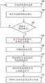
图47是图示根据一个实施例的用于将设备置于配置模式中的过程的流程图。47 is a flowchart illustrating a process for placing a device in configuration mode, according to one embodiment.
图48是图示根据一个实施例的用于选择照明器材的过程的流程图。48 is a flowchart illustrating a process for selecting lighting fixtures, according to one embodiment.
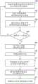
图49是图示根据一个实施例的用于选择开关模块的过程的流程图。49 is a flowchart illustrating a process for selecting a switch module, according to one embodiment.
图50A和50B是图示根据一个实施例的用于创建新控制组的过程的流程图。50A and 50B are flowcharts illustrating a process for creating a new control group, according to one embodiment.
图51是图示根据一个实施例的用于创建新占用组的过程的流程图。51 is a flowchart illustrating a process for creating a new occupancy group, according to one embodiment.
图52是图示根据一个实施例的用于合并控制组的过程的流程图。52 is a flowchart illustrating a process for merging control groups, according to one embodiment.
图53是图示根据一个实施例的用于合并占用组的过程的流程图。53 is a flowchart illustrating a process for merging occupancy groups, according to one embodiment.
图54A和54B是图示根据一个实施例的用于将设备添加到控制组的过程的流程图。54A and 54B are flowcharts illustrating a process for adding a device to a control group, according to one embodiment.
图55A和55B是图示根据一个实施例的用于将设备添加到占用组的过程的流程图。55A and 55B are flowcharts illustrating a process for adding a device to an occupancy group, according to one embodiment.
图56是图示根据一个实施例的用于改变占用组中的设置的过程的流程图。56 is a flowchart illustrating a process for changing settings in an occupancy group, according to one embodiment.
图57是图示根据一个实施例的用于对设备取消分组的过程的流程图。57 is a flowchart illustrating a process for ungrouping a device according to one embodiment.
图58是图示根据一个实施例的在占用模式和空位模式二者中的照明器材的操作的状态图。58 is a state diagram illustrating the operation of the lighting fixture in both occupied and vacant modes, according to one embodiment.
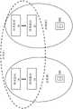
图59是图示根据一个实施例的重叠控制组和占用组的图。Figure 59 is a diagram illustrating overlapping control groups and occupancy groups according to one embodiment.
具体实施方式Detailed ways
下面阐述的实施例表示使得本领域技术人员能够实践本公开的必要信息,并且说明实践本公开的最佳模式。在鉴于附图阅读以下描述时,本领域技术人员将理解本公开的概念,并且将认识到本文中没有特别处理的这些概念的应用。应当理解的是:这些概念和应用落入本公开和所附权利要求的范围内。The embodiments set forth below represent the necessary information to enable those skilled in the art to practice the disclosure, and illustrate the best mode for practicing the disclosure. Upon reading the following description in view of the accompanying drawings, those skilled in the art will understand the concepts of the present disclosure and will recognize applications of these concepts not specifically addressed herein. It should be understood that these concepts and applications fall within the scope of the present disclosure and appended claims.
将理解的是:本文可以使用诸如“前”、“向前”、“后”、“低于”、“高于”、“上部”、“下部”、“水平”或“垂直”之类的相对术语来描述如在图中图示的一个元件、层或区域与另一个元件、层或区域的关系。将理解的是:这些术语旨在涵盖除了图中描绘的取向外的不同的设备取向。It will be understood that terms such as "front", "forward", "rear", "below", "above", "upper", "lower", "horizontal" or "vertical" may be used herein. Relative terms are used to describe one element, layer or region's relationship to another element, layer or region as illustrated in the figures. It will be understood that these terms are intended to encompass different device orientations in addition to the orientation depicted in the figures.
本公开涉及照明网络,其中网络中照明器材的控制可以分布在照明器材之中。照明器材可以被分成与不同照明区相关联的组。照明器材中的至少一些将具有一个或多个传感器或与一个或多个传感器相关联,诸如占用传感器、环境光传感器等等。在整体照明网络或各种照明区内,照明器材可以共享来自传感器的传感器数据。每个照明器材可以处理由它自己的传感器、远程独立传感器或照明器材提供的传感器数据,并根据照明器材自己的内部逻辑来处理传感器数据,以控制照明器材的操作。照明器材还可以从其它照明器材、控制节点、灯开关和调试工具接收控制输入。可以根据内部逻辑来处理控制输入连同传感器数据,以进一步增强照明器材的控制。The present disclosure relates to lighting networks in which control of lighting fixtures in the network can be distributed among the lighting fixtures. Lighting fixtures may be divided into groups associated with different lighting zones. At least some of the lighting fixtures will have or be associated with one or more sensors, such as occupancy sensors, ambient light sensors, and the like. Lighting fixtures can share sensor data from sensors within an overall lighting network or various lighting zones. Each lighting fixture can process sensor data provided by its own sensor, a remote stand-alone sensor, or the lighting fixture, and process the sensor data according to the lighting fixture's own internal logic to control the operation of the lighting fixture. Lighting fixtures can also receive control input from other lighting fixtures, control nodes, light switches, and debugging tools. Control inputs along with sensor data can be processed according to internal logic to further enhance the control of lighting fixtures.
因此,可以分散(decentralize)本公开的照明网络的控制,使得每个照明器材基本上独立于照明网络而操作;然而,每个照明器材中的内部逻辑被配置,使得照明器材可以一致地作为一组而行动。当一致地行动时,每个照明器材可以取决于针对特定照明应用的目标而以不同方式操作。照明器材还可以对所呈现的任何用户输入进行响应。Thus, the control of the lighting network of the present disclosure can be decentralized so that each lighting fixture operates substantially independently of the lighting network; however, the internal logic in each lighting fixture is configured so that the lighting fixtures can consistently function as a group action. When acting in unison, each lighting fixture may operate differently depending on the goals for a particular lighting application. The lighting fixture can also respond to any user input presented.
例如,开关可以用于开启特定区中的所有照明器材。然而,基于照明区的不同区域中的存在的环境光量或相对的占用,由各种照明器材提供的光的量可以从一个照明器材到下一个地变化。更靠近窗户的照明器材可以比靠近内部墙壁的那些照明器材提供更少的光或者不同颜色或色温的光。此外,相对于其它照明器材,更靠近人的照明器材或邻近较大组的人的那些照明器材可以提供更多的光或者不同颜色或色温的光。例如,在长的走廊中,占用者的存在不仅可以开启照明器材的走廊组,而且还可以为各种器材指定调光水平,使得用低的光水平照亮整个走廊,同时紧接着在(一个或多个)占用者周围的(一个或多个)区域具有较高的光水平。具有多个占用者的区域可以比具有更少或更多占用者的那些区域具有更高的光输出。行进的速度也可以指定相对的光输出水平。For example, a switch can be used to turn on all lighting fixtures in a particular zone. However, the amount of light provided by the various lighting fixtures may vary from one lighting fixture to the next based on the amount of ambient light present or relative occupancy in different areas of the lighting zone. Lighting fixtures closer to the windows may provide less light or light of a different color or color temperature than those nearer the interior walls. Furthermore, lighting fixtures that are closer to a person or those that are adjacent to a larger group of people may provide more light or light of a different color or color temperature relative to other lighting fixtures. For example, in a long corridor, the presence of occupants can not only turn on corridor groups of lighting fixtures, but also specify dimming levels for various fixtures, so that the entire corridor is illuminated with a low light level, while immediately following (a The area(s) around the occupant(s) have higher light levels. Areas with multiple occupants may have higher light output than those with fewer or more occupants. The speed of travel can also specify relative light output levels.
传统的照明控制系统依靠中央控制器来做出所有决定和从远处控制各种照明器材。本公开的分布式控制方法并不这样被限制。虽然可以采用中央控制器,但来自中央控制器的命令可以被视为建议或仅仅是将由每个照明器材的内部逻辑考虑的另一个输入。对于本公开特别独特的是在照明器材之间共享传感器数据的能力。能够共享传感器数据允许以其它方式独立地运转照明器材,来以协调的方式充当组。Traditional lighting control systems rely on a central controller to make all decisions and control various lighting fixtures from a distance. The distributed control method of the present disclosure is not so limited. While a central controller could be employed, commands from the central controller could be considered suggestions or just another input to be considered by the internal logic of each lighting fixture. Particularly unique to the present disclosure is the ability to share sensor data between lighting fixtures. Being able to share sensor data allows lighting fixtures to be operated independently in other ways to act as a group in a coordinated manner.
例如,照明区中的每个照明器材可以获取其自己的环境光读数,而不是仅仅作用于其自己的环境光读数,环境光读数与组中的其它照明器材共享。当照明区中的所有灯器材已经共享它们的环境光读数时,每个照明器材可以基于来自整个组的环境光读数而独立地确定平均的或最小的光输出。这样,组中的照明器材将彼此一致地调整它们的输出而同时彼此独立地操作。For example, each lighting fixture in a lighting zone can take its own ambient light reading, rather than just acting on its own ambient light reading, which is shared with other lighting fixtures in the group. When all light fixtures in a lighting zone have shared their ambient light readings, each lighting fixture may independently determine an average or minimum light output based on ambient light readings from the entire group. In this way, the lighting fixtures in the group will adjust their outputs in concert with each other while operating independently of each other.
在深入研究本公开的细节之前,描述了其中可以采用分布式照明控制系统的示例性的照明器材的概述。虽然可以在任何类型的照明系统中采用本公开的概念,但紧接在以下的描述对诸如图1-3中图示的照明器材10之类的灯槽类型的照明器材中的这些概念进行了描述。虽然公开的照明器材10采用间接的照明配置,其中光最初从光源向上发射并且然后向下反射,但直接的照明配置也可以利用本公开的概念。除了灯槽类型的照明器材外,还可以在凹陷的照明配置、壁装配的照明配置、室外照明配置等等中采用本公开的概念。对2013年8月20日提交的13/589,899、2012年10月11日提交的13/649,531和2012年9月7日提交的13/606,713的共同未决和共同转让的美国专利申请做出参考,其内容通过引用以其整体被并入本文。此外,以下所述的功能性和控制技术可以用于同时控制不同类型的照明器材以及不同组的相同或不同类型的照明器材。Before delving into the details of the present disclosure, an overview of an exemplary lighting fixture in which a distributed lighting control system may be employed is described. While the concepts of the present disclosure may be employed in any type of lighting system, the immediately following description addresses these concepts in a trough-type lighting fixture, such as the
通常,诸如照明器材10之类的灯槽类型的照明器材被设计成装配在天花板中。在大多数应用中,灯槽类型的照明器材被装配到商业、教育或政府设施的吊顶(未示出)中。如图1-3中所图示,照明器材10包括正方形或矩形的外框架12。在照明器材10的中心部分中的是两个矩形透镜14,所述透镜通常是透明的、半透明的或不透明的。反射器16从外框架12延伸到透镜14的外边缘。透镜14在反射器16的最内部分之间有效地延伸到细长散热器18,细长散热器18起作用以接合透镜14的两个内部边缘。Typically, trough-type lighting fixtures, such as
现在特别转到图2和3,散热器18的背侧提供用于LED阵列20的装配结构,LED阵列20包括在适当的基底上装配的一行或多行单独的LED。LED被取向成主要朝着凹形覆盖物22向上发射光。由覆盖物22、透镜14和散热器18的背部进行界限的体积提供了混合腔24。这样,光将从LED阵列20的LED朝着覆盖物22向上发出,并且将被向下反射通过相应的透镜14,如图3中所图示。值得注意地,不是从LED发射的所有光线将直接反射离开覆盖物22的底部并且以单反射回去通过特定透镜14。许多光线将在混合腔24内四处反弹并与其它光线有效地混合,使得合期望的均匀光被发射通过相应的透镜14。Turning now in particular to Figures 2 and 3, the backside of the
本领域技术人员将认识到:除了许多其它的变量以外,透镜14的类型、LED的类型、覆盖物22的形状和覆盖物22的底侧上的任何涂层将影响由照明器材10发射的光的量和品质。如将在下面更详细讨论的,LED阵列20可以包括不同颜色的LED,其中基于用于特定实施例的设计参数,从各种LED发射的光混合在一起以形成具有期望的色温和品质的白光。Those skilled in the art will recognize that the type of
如从图2和3中显而易见的,散热器18的细长鳍(fin)可以从照明器材10的底部可见。将LED阵列20的LED置于沿着散热器18的上侧热接触允许由LED生成的任何热有效地传递到散热器18的底侧上的细长鳍以供在其中装配了照明器材10的房间内耗散。再次,图1-3中图示的照明器材10的特定配置仅仅是其中本公开的概念适用的照明器材10的事实上无限的配置之一。As is apparent from FIGS. 2 and 3 , the elongated fins of the
继续参考图2和3,电子器件外壳26被示出装配在照明器材10的一端,并且用于容纳用于为LED阵列20供电和控制LED阵列20的电子器件的全部或一部分。这些电子器件通过适当的敷设线缆28耦合到LED阵列20。参考图4,在电子器件外壳26中提供的电子器件可以被划分成驱动器模块30和通信模块32。With continued reference to FIGS. 2 and 3 , an
在高级别,驱动器模块30通过敷设线缆28而耦合到LED阵列20,并且基于由通信模块32提供的控制信息而直接驱动LED阵列20的LED。驱动器模块30为照明器材10提供智能,并且能够以期望的方式驱动LED阵列20的LED。驱动器模块30可以被提供在单个、集成的模块上,或者被划分成两个或更多个子模块,这取决于设计者的期望。At a high level,
通信模块32充当智能通信接口,所述智能通信接口促进在驱动器模块30和其它照明器材10、远程控制系统(未示出)或便携式手持调试工具之间的通信,其还可以被配置成与远程控制系统以有线或无线方式通信。调试工具在本文中被称为调试工具36,其可以用于包括照明网络的调试的各种功能。如上所指出,这些通信可以包括在照明网络中各种照明器材10之间传感器数据、指令以及任何其它数据的共享。在本质上,通信模块32起作用以协调照明器材10之间的智能和数据的共享。The
在图4的实施例中,可以在与驱动器模块30分离的印刷电路板(PCB)上实现通信模块32。驱动器模块30和通信模块32的相应的PCB可以被配置成允许通信模块32的连接器被插入到驱动器模块30的连接器中,其中一旦通信模块32的连接器被插入到驱动器模块30的配对连接器中,通信模块32就被机械地装配或固定到驱动器模块30。In the embodiment of FIG. 4 , the
在其它实施例中,线缆可以用于连接驱动器模块30和通信模块32的相应的连接器,其它附连机制可以用于将通信模块32物理地耦合到驱动器模块30,或者驱动器模块30和通信模块32可以分离地固定到电子器件外壳26的内部。在这样的实施例中,电子器件外壳26的内部被适当地定尺寸以容纳驱动器模块30和通信模块32二者。在许多实例中,电子器件外壳26提供用于驱动器模块30和通信模块32二者的压力通风额定的(plenum rated)包封。In other embodiments, cables may be used to connect the respective connectors of the
在图4的实施例的情况下,添加或替换通信模块32需要获得到电子器件外壳26的内部的进入。如果这是不合期望的,则可以在电子器件外壳26中单独提供驱动器模块30。通信模块32可以以暴露的方式装配在电子器件外壳26的外部或者在补充的外壳34内,补充的外壳34可以直接或间接地耦合到电子器件外壳26的外部,如图5中所示。补充的外壳34可以被栓(bolt)到电子器件外壳26。补充的外壳34可以替代地通过使用卡扣配合或钩和扣机构而连接到电子器件外壳。单独或当耦合到电子器件外壳26的外表面时,补充的外壳34可以提供压力通风额定的包封。In the case of the embodiment of FIG. 4 , adding or replacing the
在其中电子器件外壳26和补充的外壳34将装配在压力通风额定的包封内的实施例中,补充的外壳34可以无需是压力通风额定的。此外,通信模块32可以直接装配到电子器件外壳26的外部而没有对于补充的外壳34的任何需要,这取决于在通信模块32中提供的电子器件的性质、将如何以及在何处装配照明器材10等等。当通信模块32促进与其它照明器材10、远程控制系统或者其它网络或辅助设备的无线通信时,其中通信模块32装配在电子器件外壳26的外部的后一实施例可以证明是有益的。在本质上,驱动器模块30可以被提供在压力通风额定的电子器件外壳26中,所述电子器件外壳26可能无助于无线通信。通信模块32可以单独地装配在电子器件外壳26的外部或者在更有助于无线通信的补充的外壳34内。根据定义的通信接口,可以在驱动器模块30和通信模块32之间提供线缆。In embodiments in which the
采用将通信模块32装配在电子器件外壳26外部的实施例可能稍微不太成本有效,但在允许通信模块32或其它辅助设备被添加到照明器材10、被服务或被替换方面提供显著的灵活性。用于通信模块32的补充的外壳34可以由压力通风额定的塑料或金属制成,并且可以被配置成容易地通过卡扣、螺钉、螺栓等等装配到电子器件外壳26,以及接纳通信模块32。通信模块32可以通过卡扣配合、螺钉、扭锁等等装配到补充的外壳34的内部。用于将通信模块32连接到驱动器模块30的敷设线缆和连接器可以采取任何可用的形式,诸如用具有RJ45连接器的标准类别5(cat 5)线缆、边缘卡连接器、盲配对连接器对、接线板和单独的导线等等。具有相对于包括驱动器模块30的电子器件外壳26而外部装配的通信模块32允许用于给定的驱动器模块30的不同类型的通信模块32的容易的现场安装。Embodiments employing
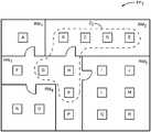
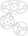
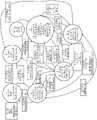
在一个实施例中,照明器材10的能力允许它们被容易地分组到不同的照明区中。参考图6,假设有18个天花板装配的照明器材10,其被唯一地引用为照明器材A至R,并且被放置在楼层平面FP1的不同房间RM1至RM4和走廊HW1中。In one embodiment, the capabilities of the
特别地,照明器材A驻留在房间RM1中;照明器材B-E驻留在房间RM2中;照明器材I、J、L、M、Q和R驻留在房间RM3中;照明器材N和O驻留在房间RM4中,并且照明器材F、G、H、K和P驻留在走廊HW1中。假设从走廊HW1到相应的房间RM1-RM4中的每一个的门是关闭的,通过使用光投射过程可以将照明器材A-R分组成五个唯一的照明区。在光投射过程期间,一个灯器材A-R将调整或调制其光输出,而其它照明器材A-R尝试监测或检测第一照明器材A-R的经调整或调制的光输出。In particular, lighting fixture A resides in room RM1 ; lighting fixture BE resides in room RM2 ; lighting fixtures I, J, L, M, Q, and R reside in room RM3 ; lighting fixtures N and O resides in room RM4 and lighting fixtures F, G, H, K and P reside in corridor HW1 . Assuming that the doors from corridor HW1 to each of the corresponding rooms RM1 -RM4 are closed, the lighting fixtures AR can be grouped into five unique lighting zones by using a light projection process. During the light casting process, one light fixture AR will adjust or modulate its light output, while the other lighting fixtures AR attempt to monitor or detect the adjusted or modulated light output of the first lighting fixture AR.
假设经调制或调整的光投射信号是可以由环境光传感器检测的可见的或近可见的(诸如红外)光信号,所述环境光传感器被提供在各种照明器材A-R中或与各种照明器材A-R相关联。最初,假设照明器材A发射可见的或近可见的光投射信号,而其余的照明器材B-R监测其环境光传感器,以检测正由集成的或相关联的环境光传感器接收的光投射信号的相对强度。再次假设房间RM1和走廊HW1之间的门是关闭的,其它照明器材A-R中没有任何一个将检测到由照明器材A提供的光投射信号,并且因而照明器材A将被单独地分组。接下来,照明器材B将提供光投射信号,并且照明器材A和C-R将开始针对正由照明器材B提供的光投射信号而进行监测。在该实例中,照明器材C将相对强地检测到光投射信号,照明器材D将更弱地检测到光投射信号,并且照明器材E将检测到微弱的光投射信号,如果真要是检测到光投射信号的话。It is assumed that the modulated or adjusted light projection signal is a visible or near-visible (such as infrared) light signal that can be detected by ambient light sensors provided in or with various lighting fixtures AR AR associated. Initially, it is assumed that lighting fixture A emits a visible or near-visible light cast signal, while the remaining lighting fixtures BR monitor their ambient light sensors to detect the relative strength of the light cast signal being received by the integrated or associated ambient light sensor . Assuming again that the door between room RM1 and hallway HW1 is closed, none of the other lighting fixtures AR will detect the light projection signal provided by lighting fixture A, and thus lighting fixtures A will be individually grouped. Next, lighting fixture B will provide a lightcast signal, and lighting fixture A and CR will begin monitoring for the lightcast signal being provided by lighting fixture B. In this example, lighting fixture C will detect the light casting signal relatively strongly, lighting fixture D will detect the light casting signal more weakly, and lighting fixture E will detect the weak light casting signal, if at all If you project a signal.
相对幅度可以被指派给由照明器材C-E中的每一个监测的光投射信号。这些幅度可以用于填充表格,诸如在图7中图示的那个,或者与特定照明器材A-R相关的其一部分。在该示例中,对于0到1.0的范围,由照明器材B发射的光投射信号被指派了通过照明器材C的0.7的相对强度,通过照明器材D的0.3,以及通过照明器材E的0.1。由于房间RM2和走廊HW1之间的门是关闭的,其它照明器材A或F-R中没有任何一个将能够检测到来自照明器材B的光投射信号。Relative amplitudes can be assigned to the light projection signals monitored by each of the lighting fixtures CE. These magnitudes may be used to populate a table, such as the one illustrated in Figure 7, or a portion thereof associated with a particular lighting fixture AR. In this example, the light cast signal emitted by lighting fixture B is assigned a relative intensity of 0.7 through lighting fixture C, 0.3 through lighting fixture D, and 0.1 through lighting fixture E for a range of 0 to 1.0. Since the door between room RM2 and hallway HW1 is closed, none of the other lighting fixtures A or FR will be able to detect the light projection signal from lighting fixture B.
接下来,照明器材C将开始提供光投射信号,并且其它照明器材A、B和D-R将开始针对由照明器材C提供的光投射信号进行监测。房间RM2中的照明器材B、D和E将检测光投射信号,并为光投射信号指派相对幅度。在图7中提供幅度。再次,照明器材A和F-R由于它们的相对位置将检测不到光投射信号。针对剩余的照明器材D-R中的每一个系统地重复此过程,使得图7的表格被完全填充。通过分析各种照明器材A-R的信号强度幅度,可以容易地将各组照明器材A-R划分成相关联的照明区。视觉上,可以容易地确定照明器材A应当单独在一区中,照明器材B-E应当在第二区中,照明器材I、J、L、M、Q和R应当在第三区中,照明器材N和O应当在第四区中,并且照明器材F、G、H、K和P应当在第五区中。这些区中的每一个直接对应于在房间RM1-RM4和走廊HW1中的各种照明器材A-R的放置。除了将不同房间的照明器材A-R简单地分组成对应的区外,基于光投射信号的相对幅度,可以容易地确定各种照明器材A-R相对于彼此的相对邻近度和放置。Next, lighting fixture C will start providing lightcast signals, and the other lighting fixtures A, B, and DR will start monitoring for the lightcast signals provided by lighting fixture C. Lighting fixtures B, D, and E in room RM2 will detect the light cast signal and assign relative amplitudes to the light cast signal. The magnitudes are provided in Figure 7. Again, lighting fixtures A and FR will not detect light projection signals due to their relative positions. This process is systematically repeated for each of the remaining lighting fixtures DR, so that the table of Figure 7 is fully populated. By analyzing the signal strength amplitudes of various lighting fixtures AR, each group of lighting fixtures AR can be easily divided into associated lighting zones. Visually, it can be easily determined that lighting fixture A should be in a zone alone, lighting fixture BE should be in a second zone, lighting fixtures I, J, L, M, Q and R should be in a third zone, lighting fixture N should be in a third zone and O should be in the fourth zone, and lighting fixtures F, G, H, K, and P should be in the fifth zone. Each of these zones corresponds directly to the placement of various lighting fixtures AR in rooms RM1 -RM4 and hallway HW1 . In addition to simply grouping the lighting fixtures AR of different rooms into corresponding zones, based on the relative magnitudes of the light projection signals, the relative proximity and placement of the various lighting fixtures AR with respect to each other can be readily determined.
如下进一步所述,各种照明器材A-R还可以监测来自彼此的RF信号强度。各种照明器材A-R之间的RF信号强度可以用于确定照明器材A-R的相对位置和之间的距离。此外,可以确定各组相对于彼此的位置和之间的相对距离。这样,通过使用光投射信号、RF信号强度或其组合可以为RF网络中的每个器材和其任何组确定相对距离和位置。结果可以用于生成照明器材A-R和照明网络中的其它元件的缩放的地图。地图也可以包括调试工具36。除了使用RF信号强度外,可以与光投射技术相关联地或代替光投射技术地使用麦克风和扬声器,以用于分组、通信等等。每个照明器材A-R可以具有麦克风或类似的声学(声波或超声波)传感器以及音频放大器和扬声器(声波或超声波)或与其相关联。As described further below, the various lighting fixtures A-R may also monitor RF signal strengths from each other. The RF signal strength between the various lighting fixtures A-R can be used to determine the relative positions and distances between the lighting fixtures A-R. In addition, the positions of the groups relative to each other and the relative distances between them can be determined. In this way, relative distances and positions can be determined for each fixture and any group thereof in the RF network by using light projection signals, RF signal strengths, or a combination thereof. The results can be used to generate scaled maps of lighting fixtures A-R and other elements in the lighting network. The map may also include
麦克风将允许照明器材拾取语音命令,如同“更亮”、“更暗”、“开”或“关”(或其它声学数据,或许是针对占用的脚步声)并处理所述声学信息。所述信息可以使得照明器材以期望的方式控制光源,向其它照明器材A-R(或其它节点)发出命令,或与其它照明器材A-R(或其它节点)共享声学信息。由照明器材A-R提供的或与其相关联的分布式麦克风的网络不仅可以确定如同声音来自哪里(是相同房间中的用户)之类的事情,而且还可以确定声源正在哪个方向和多快地移动(如果用户正在匆忙朝向出口,或甚至大喊“失火”,则也许有紧急情况,并且由于安全原因,空间应当更加良好地照亮)。The microphone will allow the lighting fixture to pick up voice commands like "brighter", "darker", "on" or "off" (or other acoustic data, perhaps footsteps for occupancy) and process the acoustic information. The information may enable lighting fixtures to control light sources in a desired manner, issue commands to other lighting fixtures AR (or other nodes), or share acoustic information with other lighting fixtures AR (or other nodes). The network of distributed microphones provided by or associated with the lighting fixture AR can not only determine where the sound is coming from (is the user in the same room) ), but also to determine in which direction and how fast the sound source is moving (if the user is rushing towards the exit, or even yelling "fire", then maybe there is an emergency and for safety reasons the space should be more well illuminated).
还有提供全部一起工作以保持办公室空间安静的噪声抑制或噪声消除的照明器材的网络的能力。可以用被配置成降低环境噪声影响的白色或粉红噪声来驱动扬声器。对于真正的噪声消除,在一个或一组照明器材A-R处由麦克风监测的环境噪声可以被反相(或者相对于环境噪声异相地播放),并且用对应的扬声器、以将为附近的占用者提供噪声消除效果的音量回放。There is also the ability to provide a network of noise-suppressing or noise-cancelling lighting fixtures that all work together to keep the office space quiet. The speakers can be driven with white or pink noise configured to reduce the impact of ambient noise. For true noise cancellation, the ambient noise monitored by the microphones at one or a group of lighting fixtures A-R can be out-of-phase (or played out of phase relative to the ambient noise) and used with corresponding speakers to provide information for nearby occupants Provides volume playback with noise cancellation effects.
值得注意地,每个照明器材A-R可以生成它自己的表格,如图7中所示,或者其一部分。例如,每个照明器材A-R可以简单地维护阵列,所述阵列存储来自其它照明器材A-R的光投射信号的相对幅度。在该实例中,照明器材A-R中的每一个将对命令进行响应,并且仅与从其中不管怎样检测到了光投射信号或检测到高于某个幅度的那些照明器材A-R共享数据。在这些实例中,每个照明器材A-R可以将自身与区有效地相关联。可替代地,所有的光投射信号数据可以被递送到主照明器材10,主照明器材10能够收集用于图7的表格的所有的数据,分析所述数据,将照明器材A-R中的每一个指派到各种区,并且向照明器材A-R传送分区信息。此外,由主照明器材10提供的处理还可以被外包给远程控制实体,诸如调试工具36或者中央控制系统。Notably, each lighting fixture A-R may generate its own table, as shown in Figure 7, or a portion thereof. For example, each lighting fixture A-R may simply maintain an array that stores the relative amplitudes of light cast signals from other lighting fixtures A-R. In this example, each of the lighting fixtures A-R would respond to the command and only share data with those lighting fixtures A-R from which the light projection signal was detected anyway or was detected above a certain magnitude. In these instances, each lighting fixture A-R may effectively associate itself with a zone. Alternatively, all light cast signal data can be delivered to the
在现有的示例中,走廊HW1中的所有门都被关闭。这样,将各种照明器材A-R分组为五个不同的区是相对明确的,其中房间RM1-RM4或走廊HW1中的所有照明器材被分组为不同的区。这样,照明器材A-R中没有任何一个被指派给多于一个区。In the existing example, all doors in hallway HW1 are closed. In this way, it is relatively straightforward to group various lighting fixtures AR into five different zones, wherein all lighting fixtures in rooms RM1 -RM4 or hallway HW1 are grouped into different zones. In this way, none of the lighting fixtures AR are assigned to more than one zone.
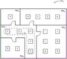
然而,可能合期望的是使某些照明器材A-R被指派给多于一个区。作为示例,如果到房间RM1中的门是正常打开的,则可能合期望的是使走廊HW1中的照明器材F和G以某种方式与用于包括照明器材A的房间RM1的区相关联。继续此概念,当照明器材A正提供光投射信号时,走廊HW1的照明器材F和G可以检测到光投射信号。类似地,当照明器材F和G正提供光投射信号时,它们可以拾取彼此的光投射信号,并且照明器材A还可以拾取照明器材F和G的光投射信号。这样,相应的照明器材A、F和G或另一个控制实体将分析光投射信号信息,并将照明器材A、F和G与区Z1相关联,如图8A中所图示。如果走廊HW1中的所有门保持打开,则光投射过程可以继续,使得房间RM2的照明器材B、C、D和E与区Z2中走廊HW1的照明器材G、H和K被分组在一起,如图8B中所图示。类似地,房间RM3的照明器材I、J、L、M、Q和R还可以与区Z3中走廊HW1的照明器材G、H和K相关联,如图8C中所示。房间RM4的照明器材N和O可以与针对区Z4的走廊HW1的照明器材F和G相关联,如图8D中所图示。However, it may be desirable to have certain lighting fixtures AR assigned to more than one zone. As an example, if the door to room RM1 is normally open, it may be desirable to have lighting fixtures F and G in hallway HW1 in some way with the zone for room RM1 that includes lighting fixture A Associated. Continuing this concept, when lighting fixture A is providing a light casting signal, lighting fixtures F and G in hallway HW1 can detect the light casting signal. Similarly, when lighting fixtures F and G are providing light casting signals, they can pick up each other's light casting signals, and lighting fixture A can also pick up lighting fixtures F and G's light casting signals. In this way, the respective lighting fixtures A, F and G or another control entity will analyze the light projection signal information and associate the lighting fixturesA , F and G with zone Z1 as illustrated in Figure 8A. If all doors in corridor HW1 remain open, the light casting process can continue such that lighting fixtures B, C, D and E of room RM2 are grouped with lighting fixtures G, H and K of corridor HW1 in zone Z2 together, as illustrated in Figure 8B. Similarly, lighting fixtures I, J, L, M, Q, and R of room RM3 may also be associated with lighting fixtures G, H, and Kof corridor HW 1in zone Z3, as shown in Figure 8C. Lighting fixtures N and O of room RM4 may be associated with lighting fixtures F and G of corridor HW1 for zone Z4 , as illustrated in Figure 8D.
参考走廊HW1,当门全部打开时,照明器材H、G、K和P可以与各种房间RM1-RM4的各种照明器材A、B、C、I、L、N和O相关联。如果这不是所期望的,则用户可以修改各种照明器材A-R的分组,使得仅仅照明器材F、G、H、K和P与表示仅用于走廊HW1的照明的区Z4相关联,如图8E中所图示。因此,通过与照明器材10中每一个的直接交互或从诸如调试工具36之类的远程控制实体可以容易地修改照明器材10的自动分组。下面进一步提供关于照明器材10如何彼此通信、共享数据并以协调的方式操作的进一步的细节。Referring to hallway HW1 , when the doors are all open, lighting fixtures H, G, K, and P can be associated with various lighting fixtures A, B, C, I, L, N, and O in various rooms RM1 -RM4 . If this is not desired, the user can modify the grouping of the various lighting fixtures AR such that only the lighting fixtures F, G, H, K, and P are associated with zone Z4 representing lighting only for corridor HW1 , as in Illustrated in Figure 8E. Accordingly, the automatic grouping of
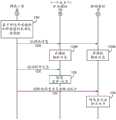
参考图9,提供部分的通信流以图示示例性的光投射过程和所述过程中涉及的每个照明器材10的功能性。被假设为在相同房间中的照明器材B-D的操作得以强调。最初,基于来自照明器材A或某个其它控制实体的指令,照明器材B决定进入光投射模式(步骤100)。决定进入光投射模式可以内部地触发、从通过有线或无线网络的外部输入触发、或者响应于接收具有某个签名的光投射信号而光学地触发。例如,照明器材B可以基于一天中的时间、周期性地、基于传感器读数或响应于手动(用户)请求而进入光投射模式。可替代地,光投射信号可以总是被监测,并且可以取光的特定关/开签名或调制的形式,其得以由进行监测的灯器材10自动检测和测量。Referring to Figure 9, a partial communication flow is provided to illustrate an exemplary light casting process and the functionality of each
在进入光投射模式时,照明器材B将直接或经由广播信号而向其它照明器材10发出指令,以寻找来自照明器材B的光投射信号。值得注意地,这些指令可以直接从一个照明器材10发送到另一个,或者可以遍及照明器材网络地从一个照明器材10中继到另一个。如所图示的,寻找由照明器材B提供的光投射信号的指令由照明器材C接收(步骤102),并且被中继到照明器材D(步骤104)。然而,可以将指令从照明器材B直接发送到照明器材D而没有中继。When entering the light projection mode, the lighting fixture B will send an instruction to
在这点上,照明器材C和D二者将开始针对将由照明器材B提供的光投射信号进行监测(步骤106和108)。因此,照明器材B将开始以某种方式调整或调制其光源,以提供光投射信号(步骤110)。值得注意地,光投射信号是将不从一个照明器材10中继到另一个的光学信号。代替地,照明器材C和D将检测和处理光投射信号,以生成分组数据(步骤112和114)。分组数据可以范围从仅仅确定是否检测到光投射信号或检测到高于给定阈值以将相对幅度指派给光投射信号,如与图7的表格相关联地讨论的。在某个时间量之后,照明器材B将停止提供光投射信号(步骤116),并提供指令以用于照明器材C进入光投射模式(步骤118)。可替代地,诸如调试工具36之类的远程控制实体可以向照明器材C提供指令以进入光投射模式。在这点上,照明器材C将决定进入光投射模式(步骤120),并且过程将针对照明器材C重复。该事件序列将针对照明网络中的照明器材10中的每一个继续。At this point, both lighting fixtures C and D will begin monitoring for the light projection signal to be provided by lighting fixture B (steps 106 and 108). Thus, lighting fixture B will begin to adjust or modulate its light source in some way to provide a light projection signal (step 110). Notably, a light projection signal is an optical signal that will not be relayed from one
关于处理光投射信号,由进行接收的照明器材10监测的光投射信号测量可以与进行发送的照明器材10、进行接收的照明器材10或二者的ID相关联。进行发送的照明器材10可以基于消息中提供的ID而被标识以寻找光投射信号(在步骤110中)或者要么包括进行发送的照明器材10的ID要么与照明器材10相关联的唯一调制信号。可以由内部或远程控制系统完成关联。此外,关联可以基于对不同照明器材10进行的光投射信号的发送加时间戳或进行同步而进行,使得进行发送的照明器材10可以与来自各种进行接收的器材10的光投射信号测量相关联。With regard to processing lightcast signals, the lightcast signal measurements monitored by the receiving
进行接收的照明器材10可以报告光投射信号测量,连同进行接收的照明器材10的相关联的ID以及可以用于将光投射信号和特定的进行发送的照明器材10相关联的同步或标识信息。时间戳或其它传感器信息可以被包括在这样的测量报告中。这些类型的光投射测量报告可以用于开发对于不同时间的诸如图7中所示那个之类的信息表格,并且包括其它传感器参数。这样,较大粒度被提供到照明器材10或灯分组的控制中,其中控制的类型可以在不同时间和/或基于来自传感器的不同输入来改变。例如,控制可以一小时改变一次,或者当监测到某些传感器读数时改变。The receiving
贯穿该过程或在过程的末尾,照明器材10中的每一个将要么交换分组数据要么向主照明器材10或远程控制实体提供分组数据,以处理分组数据并将各种照明器材10指派给对应的区(步骤122)。在主要分布式的控制过程中,在照明器材10的每一个中提供的内部逻辑将允许照明器材10基于分组数据而有效地将本身指派给适当的区。一旦照明器材10已被指派给一区或已经将自身标识为与一组照明器材10相关联,则可以在给定区内的照明器材10之间交换各种信息。该信息可以范围从传感器数据到用于控制操作的指令。Throughout the process or at the end of the process, each of the
光投射技术还可以用于检测占用或其缺乏。照明器材10(以及任何其它有光投射能力的设备)可以被配置成周期性地或相对连续地提供光投射,或许以对人眼不可见或不可感知的方式,以相对于空房间比较光投射读数。参考光投射读数中的改变可以指示占用者的存在,改变的量可以指示占用者的数量,并且改变的位置可以指示占用者的位置。返回到参考光投射读数可以指示区域已被腾空,因而潜在地消除对于通过使用传统的体热或运动传感器来检查空位的需要。Light projection techniques can also be used to detect occupancy or its lack. Lighting fixture 10 (and any other light projection capable device) may be configured to periodically or relatively continuously provide light projection, perhaps in a manner that is invisible or imperceptible to the human eye, to compare light projection relative to an empty room reading. A change in the reference light projection reading may indicate the presence of an occupant, the amount of change may indicate the number of occupants, and the location of the change may indicate the location of the occupant. Returning to the reference light projection reading may indicate that the area has been vacated, thus potentially eliminating the need to check for vacancy by using traditional body heat or motion sensors.
值得注意地,可以响应于每个通信信号或消息以及在检测到光投射信号时提供确认(acknowledge)。这些确认可以通过支持照明器材间通信的有线或无线网络来提供,或者可以通过使用一种类型的光投射信号来光学地提供,该种类型的光投射信号具有指示确认的某个调制签名。确认信号或其它响应信号可以用于交换状态、信号强度信息、对附加信息的请求等等。在给定的照明系统内,不同的通信技术(有线、无线、光投射调制)可以用于不同类型的通信、数据/信息交换、控制等等。还可以使用常规技术通过AC功率线来提供通信。Notably, an acknowledgement may be provided in response to each communication signal or message and upon detection of a lightcast signal. These confirmations may be provided through wired or wireless networks that support communication between lighting fixtures, or may be provided optically through the use of a type of light-cast signal with some modulated signature indicative of the confirmation. Acknowledgement signals or other response signals may be used to exchange status, signal strength information, requests for additional information, and the like. Within a given lighting system, different communication technologies (wired, wireless, light cast modulation) can be used for different types of communication, data/information exchange, control, etc. Communication may also be provided over the AC power line using conventional techniques.
参考图10,提供部分的通信流来图示通常可以如何在一区或照明网络内的各种照明器材10之间交换传感器数据。假设照明器材B、C和D已被指派给特定区。在操作期间,照明器材B、C和D将监测和交换传感器数据并共同使用传感器数据来确定如何调整其各自的光输出。最初,照明器材B将监测其传感器数据,所述传感器数据是来自相关联的环境光、占用或其它传感器的数据(步骤200)。照明器材B将发送其传感器数据到区中的其它照明器材C和D(步骤202)。同时,照明器材C正监测其传感器数据(步骤204),并向照明器材B和D提供传感器数据(步骤206)。类似地,照明器材D正监测其传感器数据并且(步骤208),并向照明器材C和B提供传感器数据(步骤210)。因而,照明器材B、C和D中的每一个可以访问其自身的传感器数据以及其区中其它照明器材的传感器数据。虽然此示例是面向区的,但整个照明网络中的所有照明器材10可以正在向彼此提供所有传感器数据或某些传感器数据或者照明网络中照明器材10的所有或某几个。在给定的区内,一组器材可以将本身分离成一个或多个分离的(或子)区,如果它们的环境光传感器比区中其余的照明器材检测到更多的光。这可以对应于最接近窗户的一组灯。Referring to Figure 10, a partial communication flow is provided to illustrate how sensor data may generally be exchanged between
以相对连续的方式,照明器材B将处理来自它自己的传感器的传感器数据以及来自其它照明器材C和D的传感器数据(步骤212),并基于传感器数据而确定如何调整其光输出(步骤214)。因此,照明器材B独立地控制其光输出;然而,当精确地确定如何调整其光输出时,照明器材B的内部逻辑不仅可以考虑其自己的传感器数据,而且还考虑其它照明器材C和D的传感器数据。以独立但一致的方式,照明器材C和D还将处理它们的传感器数据和来自其它照明器材的传感器数据,并基于传感器数据而调整其光输出(步骤216-222)。In a relatively continuous manner, lighting fixture B will process the sensor data from its own sensors and the sensor data from other lighting fixtures C and D (step 212 ) and determine how to adjust its light output based on the sensor data (step 214 ) . Thus, lighting fixture B independently controls its light output; however, when determining precisely how to adjust its light output, lighting fixture B's internal logic can take into account not only its own sensor data, but also the other lighting fixtures C and D's sensor data. In an independent but consistent manner, lighting fixtures C and D will also process their sensor data and sensor data from other lighting fixtures and adjust their light output based on the sensor data (steps 216-222).
有趣地,不同照明器材B、C和D的内部逻辑可以被配置成彼此相同或彼此不同地起作用。例如,照明器材B、C和D可以将与该区中的其它照明器材B、C和D相同的加权应用到传感器数据。因而,给定来自它自己的传感器和来自其它照明器材B、C和D的相同传感器数据,每个照明器材B、C和D将以确切相同的方式调整其光输出。如果内部逻辑在照明器材B、C和D之间变化,则给定相同的传感器数据,相应的照明器材B、C和D的光输出可能变化。值得注意地,传感器数据可以包括来自不同类型的传感器的数据。例如,来自环境光和占用传感器二者的传感器数据可以如由每个照明器材B、C和D的内部逻辑所指定的那样交换和处理以确定如何调整其各自的光输出。Interestingly, the internal logic of the different lighting fixtures B, C and D can be configured to function the same as each other or differently from each other. For example, lighting fixtures B, C, and D may apply the same weighting to the sensor data as other lighting fixtures B, C, and D in the zone. Thus, given the same sensor data from its own sensor and from other lighting fixtures B, C and D, each lighting fixture B, C and D will adjust its light output in exactly the same way. If the internal logic varies between lighting fixtures B, C, and D, given the same sensor data, the light output of the corresponding lighting fixtures B, C, and D may vary. Notably, sensor data may include data from different types of sensors. For example, sensor data from both ambient light and occupancy sensors may be exchanged and processed as specified by the internal logic of each lighting fixture B, C, and D to determine how to adjust their respective light output.
除了交换传感器数据并鉴于其而控制操作外,照明器材B、C和D还可以使用它们自己的传感器数据以及从其它照明器材B、C和D接收的传感器数据,以控制其它照明器材B、C和D的操作。参考图11,示出部分的通信流,以图示此概念。最初,假设照明器材B和照明器材D正从它们各自的传感器收集传感器数据,并且向照明器材C提供该传感器数据(步骤300和302)。虽然未图示,但照明器材C可以在向其它照明器材B和D提供其传感器数据。照明器材C还可以在监测它自己的传感器数据(步骤304),并且处理来自它自己的传感器的传感器数据以及来自其它照明器材B和D的传感器数据(步骤306),以生成用于照明器材B和C的指令(步骤308)。一旦指令被生成,它们可以被提供给相应的照明器材B和D(步骤310和312)。因此,照明器材B可以基于从照明器材C提供的指令、照明器材D的传感器数据或其组合而调整其光输出,这取决于照明器材B的内部逻辑(步骤314)。照明器材C可以基于它自己的传感器数据或者它自己的传感器数据和从照明器材B和D接收的传感器数据的组合而调整其光输出(步骤316)。如同照明器材B,照明器材D可以基于从照明器材C接收的指令、来自照明器材D的传感器数据或其组合而调整其光输出(步骤318)。In addition to exchanging sensor data and controlling operations in view of it, lighting fixtures B, C and D can use their own sensor data and sensor data received from other lighting fixtures B, C and D to control other lighting fixtures B, C and the operation of D. Referring to Figure 11, a partial communication flow is shown to illustrate this concept. Initially, it is assumed that lighting fixture B and lighting fixture D are collecting sensor data from their respective sensors and providing this sensor data to lighting fixture C (
作为实际的示例,照明器材B、C和D可以共享环境光信息,环境光信息可以指示光输出的强度、光输出的色温、光输出的颜色或其任何组合。然而,照明器材C还可以与占用传感器相关联。这样,由照明器材C提供给照明器材B和D的指令可以指令照明器材B和D开启并以某个水平、色温或颜色而提供光输出。照明器材B和D可以直接对这些指令进行响应,或者可以鉴于其各自的内部逻辑来处理这些指令,以确定是否开启以及如何控制各自的光输出。这样,从一个照明器材10向另一个提供的指令可以被视为绝对命令并且相应地被响应,或者可以视为仅仅是“建议”,这取决于接收指令的照明器材10的编程。例如,在其中照明器材C正指令照明器材B开启的以上场景中,可能有在照明器材B处测量的充足的阳光,其否定对于照明器材B开启的需要。或者,如果照明器材B确实决定开启,则光的颜色、强度或色温可以通过在照明器材B处测量的阳光的量和颜色来调整。再次,在本公开中所述的分布式控制允许这些照明器材10独立但一致地操作,如果内部逻辑如此指示的话。As a practical example, lighting fixtures B, C, and D may share ambient light information, which may indicate the intensity of the light output, the color temperature of the light output, the color of the light output, or any combination thereof. However, lighting fixture C may also be associated with an occupancy sensor. As such, the instructions provided by lighting fixture C to lighting fixtures B and D may instruct lighting fixtures B and D to turn on and provide light output at a certain level, color temperature, or color. Lighting fixtures B and D may respond directly to these commands, or may process these commands in view of their respective internal logic to determine whether to turn on and how to control their respective light outputs. As such, instructions provided from one
如图12的部分通信流中所示,从一个照明器材10向另一个提供的指令可以通过中间照明器材10中继。此外,基于内部逻辑、传感器数据等等,指令可以在它们从一个照明器材10被传递到另一个时被修改。最初,假设照明器材A、调试工具36或某种其它控制点、开关或节点向照明器材B提供指令(步骤400)。照明器材B可以接收这些指令,并将未修改的指令传递到一个或多个其它照明器材10(诸如照明器材C)(步骤402)。照明器材B然后可以监测它自己的传感器数据(步骤404),处理传感器数据(步骤406),并基于它自己的传感器数据、其它的传感器数据、提供的指令或其组合而生成用于包括照明器材C的其它照明器材10的经修改的指令(步骤408)。经修改的指令可以被发送到其它照明器材10,诸如照明器材C(步骤410)。照明器材B然后能够基于它自己的传感器数据、其它的传感器数据和接收的指令而调整其光输出(步骤418)。照明器材C可以监测它自己的传感器数据(步骤412),处理其传感器数据(步骤414),并且然后基于各种传感器数据、经修改的指令、未修改的指令或其组合来调整其光输出(步骤416)。通过共享传感器数据、彼此通信以及根据内部逻辑而独立操作的这种能力,各种照明器材10向照明配置者提供极大的灵活性。As shown in the partial communication flow of FIG. 12 , instructions provided from one
参考图13A和13B,图示了具有照明器材A-R的楼层平面FP2。在图13A中,照明器材A-R可以被分组,使得离房间的有窗户的端最远的六个照明器材A、B、G、H、M和N在开启时处于其完全光输出,在房间中间的六个照明器材C、D、I、J、O和P在开启时正在产生中等光输出,并且最靠近窗户的六个照明器材E、F、K、L、Q和R在开启时正在产生最少量的光输出,并且阳光由照明器材A-R的多个的一个检测到。在此实例中,具有最多环境阳光的房间的部分将采用最少量的人造光。照明器材A-R中的每一个与对于房间的整体区和对于六个照明器材A-R的三个集合中的每一个的不同的子区相关联。虽然照明器材A-R被划分成在检测到环境阳光时提供三个不同光输出水平的三组,但照明器材A-R可以被配置成使得当检测到环境阳光时照明器材A-R中的每一个以不同强度(或颜色和色温)提供光输出。Referring to Figures 13A and 13B, a floor plan FP2 with lighting fixtures A-R is illustrated. In Figure 13A, lighting fixtures A-R can be grouped such that the six lighting fixtures A, B, G, H, M, and N furthest from the windowed end of the room are at their full light output when turned on, in the middle of the room The six fixtures C, D, I, J, O, and P are producing moderate light output when turned on, and the six fixtures E, F, K, L, Q, and R closest to the window are producing when turned on A minimal amount of light output, and sunlight is detected by one of the plurality of lighting fixtures A-R. In this example, the parts of the room that have the most ambient sunlight will use the least amount of artificial light. Each of the lighting fixtures A-R is associated with a different sub-zone for the overall zone of the room and for each of the three sets of six lighting fixtures A-R. While the lighting fixtures A-R are divided into three groups that provide three different light output levels when ambient sunlight is detected, the lighting fixtures A-R may be configured such that each of the lighting fixtures A-R at a different intensity ( or color and color temperature) to provide light output.
例如并且参考图13B,照明器材A-R中的每一个可以视为在相同的区中,但是光输出经受跨整个区而发生的梯度。梯度可以是线性的或非线性的。例如,离任何窗户最远的照明器材M将提供最多的光输出,而很可能在接收最多环境阳光的区域中的照明器材F将提供最少的光输出。For example and with reference to Figure 13B, each of the lighting fixtures A-R may be considered to be in the same zone, but the light output is subject to a gradient that occurs across the entire zone. Gradients can be linear or non-linear. For example, the lighting fixtures M furthest from any window will provide the most light output, while the lighting fixtures F, likely in areas that receive the most ambient sunlight, will provide the least light output.
根据在照明器材A-R之中共享的所定义的线性或非线性梯度,照明器材M和F之间的每个照明器材可以提供连续减少量的光输出。值得注意地,梯度可以由所有的照明器材A-R已知,其中基于可得到的环境阳光的量而连续地调整梯度。因而,当照明器材F检测到最大量的环境阳光时,梯度的有效斜率最大,其中照明器材M和F之间的光输出差分最大。在夜间,当没有环境阳光和非常少的光时,如果有任何的话,是通过窗户接收的,基于最靠近窗户的那些照明器材A-R与区中的其它照明器材A-R共享环境光传感器数据,所有的照明器材A-R可以确定提供相同量的光输出。再次,照明器材A-R能够基于其自己的或共享的传感器数据而独立地起作用。用于基于各种传感器数据而控制光输出的内部逻辑可以被固定、手动调整或者基于照明器材A-R之间的交互而动态地调整。Each lighting fixture between lighting fixtures M and F may provide a continuously decreasing amount of light output according to a defined linear or non-linear gradient shared among lighting fixtures A-R. Notably, the gradient may be known by all lighting fixtures A-R, where the gradient is continuously adjusted based on the amount of ambient sunlight available. Thus, the effective slope of the gradient is greatest when lighting fixture F detects the greatest amount of ambient sunlight, where the light output difference between lighting fixtures M and F is greatest. At night, when there is no ambient sunlight and very little light, if any, is received through a window, based on those lighting fixtures A-R closest to the window sharing ambient light sensor data with other lighting fixtures A-R in the zone, all Lighting fixtures A-R may be determined to provide the same amount of light output. Again, the lighting fixtures A-R can function independently based on their own or shared sensor data. The internal logic for controlling light output based on various sensor data may be fixed, manually adjusted, or dynamically adjusted based on the interaction between the lighting fixtures A-R.
继续参考图13A和13B,假设门口(未示出)位于靠近照明器材A处,并且至少照明器材A具有占用传感器SO或与占用传感器SO相关联。进一步假设:所有的或至少许多个照明器材A-R具有环境光传感器SA或与环境光传感器SA相关联,并且当前处于关状态。当某人通过进入房间的门口走进房间中时,占用传感器SO将提供占用的信号,占用的信号将向照明器材A告警房间现在被占用。作为响应,照明器材A可以被编程以指令所有的其它照明器材B-R开启。可替代地,照明器材A可以与其它照明器材B-R共享其占用传感器(或其它传感器)信息,其它照明器材B-R将独立地使用其自己的内部逻辑来处理占用传感器信息并开启其自身。With continued reference to Figures 13A and 13B, assume that a doorway (not shown) is located near lighting fixture A, and at least lighting fixture A has or is associated with anoccupancy sensorSO . Assume further that all or at least many lighting fixturesAR have or are associated with an ambient light sensorSA and are currently in an off state. When someone walks into the room through the doorway into the room, the occupancy sensorSO will provide a signal of occupancy, which will alert lighting fixture A that the room is now occupied. In response, lighting fixture A may be programmed to command all other lighting fixtures BR to turn on. Alternatively, lighting fixture A may share its occupancy sensor (or other sensor) information with other lighting fixtures BR, which will independently use their own internal logic to process the occupancy sensor information and turn on itself.
可替代地,照明器材A可以仅仅指令与一区相关联的子组转变。在后一种情况下,照明器材A可以被编程以仅仅指令照明器材A、B、G、H、M和N开启。房间中的其它区[C、D、I、J、O、P]和[E、F、K、L、Q、R]可以仅仅在与那些区相关联的占用传感器SO检测到占用者时开启。在任一情况下,所有的照明器材A-R可以监测通过窗户以及或许门口接收的环境光的量,并且一旦被开启就单独地控制光的水平、颜色和色温以输出。水平、颜色和色温可以随着环境光水平改变而动态地改变。Alternatively, lighting fixture A may instruct only a subset of transitions associated with a zone. In the latter case, lighting fixture A may be programmed to only command lighting fixtures A, B, G, H, M, and N to turn on. Other zones [C, D, I, J,O , P] and [E, F, K, L, Q, R] in the room can only be used when the occupancy sensor SO associated with those zones detects an occupant on. In either case, all lighting fixtures AR can monitor the amount of ambient light received through windows and perhaps doorways, and individually control the level, color and color temperature of the light to output once turned on. Level, color and color temperature can be dynamically changed as the ambient light level changes.
代替于由另一个照明器材指令开启,照明器材A-R中的每一个可以具有占用传感器SO或与占用传感器SO关联,并且独立地对检测到占用者而作出反应。占用传感器SO可以采用能够检测人的移动或存在的任何可用类型的运动、热等传感器技术。照明器材A-R还可以被编程以在检测到来自另一个照明器材A-R的光时开启。因而,当照明器材A响应于检测到占用者而开启时,其它照明器材B-R将检测来自照明器材A的光的存在,并且响应于检测到来自开启的照明器材A的光而开启。Instead of being commanded to turn on by another lighting fixture, each of the lighting fixtures AR may have or be associated with anoccupancy sensorSO and independently react to detecting an occupant. The occupancy sensorSO may employ any available type of motion, heat, etc. sensor technology capable of detecting the movement or presence of a person. A lighting fixture AR can also be programmed to turn on when light from another lighting fixture AR is detected. Thus, when lighting fixture A turns on in response to detecting an occupant, other lighting fixtures BR will detect the presence of light from lighting fixture A and turn on in response to detecting light from lighting fixture A that is turned on.
在某些实施例中,只有照明器材A-R之一需要被有线或无线地耦合到开/关的开关或调光器。如果照明器材A耦合到开关或调光器,则照明器材A可以指令其它照明器材开启(以及调光到某个水平)。可替代地,照明器材A可以仅仅开启到某个输出水平。其它照明器材B-R将作为照明器材A开启的结果而检测到光,以及或许通过相关联的环境光传感器SA的相对的调光水平,并开启到某个输出水平。如果未感测到,则可以通过照明器材A而与照明器材B-R共享相对的调光水平。In some embodiments, only one of the lighting fixtures AR needs to be wired or wirelessly coupled to the on/off switch or dimmer. If lighting fixture A is coupled to a switch or dimmer, lighting fixture A can instruct other lighting fixtures to turn on (and dim to a certain level). Alternatively, lighting fixture A may only be turned on to a certain output level. The other lighting fixtures BR will detect light as a result of lighting fixtureA turning on, and perhaps the relative dimming level by the associated ambient light sensor SA, and turn on to a certain output level. If not sensed, the relative dimming level may be shared by lighting fixture A with lighting fixture BR.
网络的智能实际上是无限的,并且给予对于高度智能照明系统的潜力。例如,照明器材A-R可以能够确定它们到彼此的相对位置(或被编程有它们到彼此的相对位置)。使用占用传感器SO,照明器材A-R的集体组可以被配置成基于历史占用数据而开发预测算法,并使用这些预测算法来确定要保持灯亮多长时间,随着人走进房间或走下走廊而应当开启什么灯,等等。例如,沿着走廊的照明器材10可以顺序地和恰好地在人走下走廊之前开启。灯还可以顺序地以及在人的后面关断。灯的顺序开启可以由第一照明器材10检测到人而触发,但走廊中剩余的照明器材10可以基于在预测算法中体现的历史步行速度、路径等等而顺序开启。照明器材10中的每一个可以共享传感器数据、指令等等,并且然后鉴于此共享的信息而独立地操作。The intelligence of the network is virtually limitless and offers potential for highly intelligent lighting systems. For example, the lighting fixtures AR may be able to determine their relative positions to each other (or be programmed with their relative positions to each other). Using occupancy sensorsS0 , a collective group of lighting fixtures AR can be configured to develop predictive algorithms based on historical occupancy data, and use these predictive algorithms to determine how long to keep lights on, as people walk into a room or down a hallway. What lights should be turned on, etc. For example,
下面用两个示例图示“灯跟踪”的以上概念。对于第一示例,对图8A做出参考,图8A为沿着走廊HW1行走的人提供灯跟踪示例。假设人在靠近照明器材F处进入走廊,并在靠近照明器材P处离开走廊。还假设照明器材F、G、H、K和P中的每一个包括占用传感器SO。当人在靠近照明器材F处进入走廊时,照明器材F将经由其占用传感器SO感测人的存在并将自身开启。照明器材F可以被编程以向照明器材G告警:照明器材F已经检测到用户。照明器材G可以知道照明器材H当前关断,并且由于照明器材F正检测到人的存在,照明器材G可以以预测方式将自身开启。如果照明器材G随后检测到人的存在,则它可以向照明器材H和照明器材F告警。一旦照明器材H接收到照明器材G的占用传感器已经检测到人的指示,它就可以开启。如果照明器材H通过其占用传感器SO检测到人的存在,则它可以向照明器材K、照明器材G和照明器材F告警。照明器材F可以将该信息视为人正沿着走廊HW1、朝着照明器材P行进的指示,并且从而关断,因为它可能不再被需要。照明器材G可以暂时保持开启,而照明器材K将以预测方式开启。此过程可以继续,使得一个、两个或更多个灯在靠近人的当前位置在走廊HW1中开启。邻近的占用传感器检测之间的时间还可以用于估计人正在行进所按的速度。这可以用于预测人或对象去往何处。例如,如果某人正在减速以进入房间,则房间中的灯可以相应地反应。The above concept of "light tracking" is illustrated below with two examples. For a first example, reference is made to FIG. 8A , which provides an example of light tracking for a person walking along hallway HW1 . Suppose a person enters the corridor near lighting fixture F and exits the corridor near lighting fixture P. Also assume that each of lighting fixtures F, G, H, K, and P includes an occupancy sensorSO . When a person enters the hallway close to the lighting fixture F, the lighting fixture F will sense the presence of the person via its occupancy sensorSO and turn itself on. Lighting fixture F may be programmed to alert lighting fixture G that lighting fixture F has detected a user. Lighting fixture G can know that lighting fixture H is currently off, and since lighting fixture F is detecting the presence of a person, lighting fixture G can turn itself on in a predictive manner. If lighting fixture G subsequently detects the presence of a person, it may alert lighting fixture H and lighting fixture F. Once lighting fixture H receives an indication that lighting fixture G's occupancy sensor has detected a person, it can be turned on. If lighting fixture Hdetects the presence of a person through its occupancy sensor SO, it can alert lighting fixture K, lighting fixture G, and lighting fixture F. Lighting fixture F may take this information as an indication that a person is traveling down corridor HW1 towards lighting fixture P, and thus turn off, since it may no longer be needed. Lighting fixture G may remain on temporarily, while lighting fixture K will turn on in a predictive manner. This process may continue such that one, two or more lights are turned on in hallway HW1 near the person's current location. The time between adjacent occupancy sensor detections can also be used to estimate the speed at which a person is traveling. This can be used to predict where people or objects are going. For example, if someone is slowing down to enter a room, the lights in the room can react accordingly.
此外,灯彼此通信并共享其占用传感器信息的能力允许走廊HW1中的照明器材的组照明人的当前位置,并且在人到达特定的照明器材之前预测地开启照明器材。当然,当照明器材F检测到人的存在时,走廊HW1中的所有照明器材可以开启,并且当在某个时间量之后照明器材F、G、H、K和P中没有任何一个检测到人的存在时关断。作为又一个跟踪示例,照明器材F、G、H、K和P中的每一个可以仅仅当它们检测到人的存在时开启,并且在不再检测到人的存在的某个时间量之后或组中的照明器材中没有任何一个检测到人的存在时关断。Furthermore, the ability of the lights to communicate with each other and share their occupancy sensor information allows the group of lighting fixtures in hallway HW1 to illuminate the current location of a person, and to predictively turn on the lighting fixture before the person arrives at a particular lighting fixture. Of course, all lighting fixtures in hallway HW1 can be turned on when lighting fixture F detects the presence of a person, and when after a certain amount of time none of lighting fixtures F, G, H, K, and P detect a person is turned off in the presence of . As yet another tracking example, lighting fixtures F, G, H, K, and P may each be turned on only when they detect the presence of a person, and after a certain amount of time or group of times when the presence of a person is no longer detected Turn off when none of the lighting fixtures in the device detect the presence of a person.
跟踪概念同等地适用于更大的区域,诸如房间或室外区域。对于以下示例,对图13A或13B做出参考。在过分简单化的示例中,照明器材A-R中的每一个可以包括占用传感器SO并被如下编程。如果用于特定照明器材A-R的占用传感器SO检测到人的存在,则该照明器材将开启,并且立即指令邻近的照明器材开启,如果它们不是已经开启的话。这样,照明器材A-R中的不同个体或其组可以开启并跟踪房间中的人。检测到人的存在的照明器材(以及由该照明器材指令开启的那些器材)可以在不再检测到人的存在之后的设置的时间段内保持开启。虽然在前的示例是房间占用者的过分简单化的跟踪以及基于其而选择性地开启或关断照明器材,但还可以采用预测算法。例如,假设人在靠近照明器材M处进入房间并对角地行走穿过房间到靠近照明器材F的相对的角落。当照明器材M检测到人的存在时,它可以开启并指令照明器材G、H和N开启。剩余的照明器材将保持关断。如果照明器材N随后检测到人的存在,则它将保持开启并将指令照明器材I和O开启,因为它知道照明器材M首先检测到人并且现在照明器材N正检测到人。当照明器材I检测到人时,它也可以告警照明器材B、C、D、H、J、N、O和P以开启,并且也可以告警照明器材M。照明器材M可能不再检测到人的存在,并且可以基于它不再检测到人的存在以及照明器材N和I已经随后检测到人的存在的认知而关断。此过程可以跨房间而继续,随着照明器材J、K、E、L和F渐次开启,随着在人已经离开房间的对应区域之后照明器材M、H、N等等关断。因而,基本的跟踪和预测控制可以用于实际上任何环境中,以选择性地开启和关断或以其它方式控制在房间、组等等中的照明器材。The tracking concept applies equally to larger areas, such as rooms or outdoor areas. For the following examples, reference is made to Figure 13A or 13B. In an oversimplified example, each of the lighting fixtures AR may include an occupancy sensorSO and be programmed as follows. If the occupancy sensor SO for a particular lighting fixtureAR detects the presence of a person, that lighting fixture will turn on and immediately command adjacent lighting fixtures to turn on, if they are not already on. In this way, different individuals or groups in the lighting fixture AR can turn on and track people in the room. Lighting fixtures that detect the presence of a person (and those that are instructed to turn on by the lighting fixture) may remain on for a set period of time after the presence of a person is no longer detected. While the previous example was an oversimplified tracking of room occupants and selectively turning lighting fixtures on or off based thereon, predictive algorithms can also be employed. For example, suppose a person enters a room near lighting fixture M and walks diagonally across the room to an opposite corner near lighting fixture F. When lighting fixture M detects the presence of a person, it can turn on and command lighting fixtures G, H and N to turn on. The remaining lighting fixtures will remain off. If lighting fixture N subsequently detects the presence of a person, it will remain on and will instruct lighting fixtures I and O to turn on, knowing that lighting fixture M detected a person first and now lighting fixture N is detecting a person. When lighting fixture I detects a person, it can also alert lighting fixtures B, C, D, H, J, N, O, and P to turn on, and can alert lighting fixture M as well. Lighting fixture M may no longer detect the presence of a person, and may switch off based on the knowledge that it no longer detects the presence of a person and that lighting fixtures N and I have subsequently detected the presence of a person. This process can continue across the room, with lighting fixtures J, K, E, L, and F being turned on progressively, with lighting fixtures M, H, N, etc. turning off after the person has left the corresponding area of the room. Thus, basic tracking and predictive control can be used in virtually any environment to selectively turn on and off or otherwise control lighting fixtures in rooms, groups, and the like.
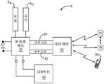
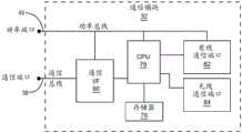
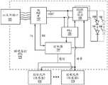
现在转到图14,根据一个实施例而提供照明器材10的框图。为了讨论的目的而假设驱动器模块30、通信模块32和LED阵列20最终连接以形成照明器材10的核心,并且通信模块32被配置成通过有线或无线技术而与其它照明器材10、调试工具36或其它控制实体双向通信。在此实施例中,在驱动器模块30和通信模块32之间使用标准的通信接口和第一或标准协议。此标准协议允许不同的驱动器模块30与不同的通信模块32通信并由不同的通信模块32控制,假设驱动器模块30和通信模块32二者根据由标准通信接口使用的标准协议而操作。术语“标准协议”被定义成意指任何类型的已知或将来开发的专有的或工业标准化的协议。Turning now to FIG. 14, a block diagram of
在图示的实施例中,驱动器模块30和通信模块32经由通信(COMM)总线38和功率(PWR)总线40耦合。通信总线38允许通信模块32从驱动器模块30接收信息以及控制驱动器模块30。示例性的通信总线38是众所周知的集成电路间(I2C)总线,其是串行总线并且典型地用采用数据和时钟线的两线接口来实现。其它可用的总线包括:串行外围接口(SPI)总线、Dallas Semiconductor公司的1线串行总线、通用串行总线(USB)、RS-232,MicrochipTechnology公司的UNI/O®等等。In the illustrated embodiment, the
在此实施例中,驱动器模块30被配置成从环境光传感器SA和占用传感器SO收集数据并驱动LED阵列20的LED。从环境光传感器SA和占用传感器SO收集的数据以及驱动器模块30的任何其它操作参数可以与通信模块32共享。这样,通信模块32可以收集关于驱动器模块30的配置或操作的数据以及由LED阵列20、环境光传感器SA和占用传感器SO使得可用于驱动器模块30的任何信息。收集的数据可以由通信模块32用于控制驱动器模块30如何操作,可以与其它照明器材10或控制实体共享,或者可以被处理以生成被发送到其它照明器材10的指令。In this embodiment,
通信模块32还可以全部地或部分地由诸如调试工具36或另一个照明器材10之类的远程控制实体来控制。通常,通信模块32将处理由其它照明器材10或远程控制实体提供的传感器数据和指令,并且然后通过通信总线38向驱动器模块30提供指令。看它的可替代方式是通信模块32促进包括占用感测、环境光感测、调光器开关设置等的系统的信息的共享,并将此信息提供给驱动器模块30,所述驱动器模块30然后使用它自己的内部逻辑来确定要采取(一个或多个)什么行动。适当时,驱动器模块30将通过控制被提供给LED阵列20的驱动电流或电压来进行响应。以下提供用于假设的协议的示例性命令集。
示例性的命令集Exemplary command set
以上表格具有四列:命令、源、接收者和描述。命令表示从通信模块32传递到驱动器模块30或者从驱动器模块30传递到通信模块32的实际指令。源标识命令的发送者。接收者标识命令的所意图的接收方。通信列提供命令的描述。例如,“开/关”命令由通信模块32发送给驱动器模块30,并且有效地允许通信模块32指令驱动器模块30开启或者关断LED阵列20。“色温”命令允许通信模块32指令驱动器模块30以生成期望的色温的方式驱动LED阵列20。“色温”命令实际上可以包括期望的色温或对可用色温的参考。The above table has four columns: Command, Source, Receiver, and Description. Commands represent actual instructions passed from the
“调光水平”命令被从通信模块32发送到驱动器模块30,以基于期望的调光水平来设置整体光水平。“器材ID”命令允许驱动器模块30向通信模块32标识其自身。“健康”命令允许驱动器模块30向通信模块32发送关于其操作能力或者换句话说健康的信息。“功率使用”命令允许驱动器模块30告诉通信模块32平均或在任何给定时间有多少功率正由驱动器模块30使用,这取决于驱动器模块30的能力。“使用”命令允许驱动器模块30将总使用小时、一致使用的小时等等标识给通信模块32。“寿命”命令允许驱动器模块30向通信模块32提供驱动器模块30、LED阵列20或其组合的有用剩余寿命的估计。基于驱动器模块30的能力,剩余寿命的量可以把过去的使用、环境温度、功率水平等等作为因子。A "dimming level" command is sent from the
“区ID”命令允许驱动器模块30告诉通信模块32:驱动器模块30驻留在哪个区中。当其它照明器材10或远程控制实体正在控制多个照明器材并正在收集关于照明器材10驻留在其中的区的信息时,该命令是有用的。“温度”命令允许驱动器模块30向通信模块32提供针对驱动器模块30或LED阵列20的环境温度信息。The "zone ID" command allows the
“紧急情况使能”命令允许驱动器模块30告诉通信模块32:照明器材10是紧急情况使能的器材,其可以用于紧急情况照明。“紧急情况健康”命令允许驱动器模块30提供与驱动器模块30或照明器材10起紧急情况照明器材作用的能力有关的信息。在简单实施例中,命令可以提供在紧急情况的情况下已经被使得可用于驱动照明器材10的紧急情况备用电池的状态。“紧急情况测试”命令允许通信模块32向驱动器模块30发送指令,以运行紧急情况照明测试,以确保照明器材10可以在紧急情况照明模式下操作,如果如此要求的话。“紧急情况通过”命令允许驱动器模块30告知通信模块32:紧急情况测试通过(或未能通过)。以上命令主要描述信息流的方向。然而,协议可以允许通信模块32或驱动器模块30选择性地或周期性地来具体地或批量地请求这种或其它信息中的任一个。The "emergency enabled" command allows the
用于在驱动器模块30和通信模块32之间通信的标准通信接口和标准协议的使用支持用于驱动器模块30和通信模块32的模块化方法。例如,不同的制造商可以做出与特定的驱动器模块30对接的不同的通信模块32。不同的通信模块32可以被配置成基于不同的照明应用、可用的特征、价格点等等而不同地驱动驱动器模块30。这样,通信模块32可以被配置成与不同类型的驱动器模块30通信。一旦通信模块32耦合到驱动器模块30,通信模块32就标识驱动器模块30的类型,并将相应地与驱动器模块30对接。此外,驱动器模块30可以能够在用于不同照明参数的各种范围上操作。不同的通信模块32可以被配置成在不同程度上控制这些参数。第一通信模块32可以仅被给予对有限参数集的访问,其中另一个通信模块32可以被给予对大得多的参数集的访问。以下表格提供用于给定的驱动器模块30的示例性参数集。The use of standard communication interfaces and standard protocols for communication between
参数parameter
以上表格中的参数可以表示用于给定的驱动器模块30的可用控制点。给定的参数集可以在制造期间被指派给驱动器模块30,或者可以在照明器材10的安装期间或在将通信模块32与驱动器模块30相关联时由通信模块32设置。参数集包括各种参数,诸如脉冲宽度调制(PWM)调光频率、最大光水平和色温。参数集表示用于这些参数中每一个的可允许的范围。可以在操作等等期间由通信模块32或远程控制系统在参数集中标识的范围内设置每个参数,这取决于设计者的期望或特定应用。The parameters in the above table may represent the available control points for a given
作为示例,用于示例性的参数集的最大光水平指示:它可以从驱动器模块30和相关联的LED阵列20的能力的从50%到100%的任何地方被设置。如果采用照明器材10的照明系统的最终用户或所有者发起适当的指令,则最大光水平可以在适当的参数字段中被设置到80%。这样,驱动器模块30将不会驱动LED阵列20到超过80%,即使通信模块32向驱动器模块30提供命令以将照明水平增加到高于其最大能力的80%。这些参数可以存储在驱动器模块30中或通信模块32中在非易失性存储器中。As an example, the maximum light level indication for the exemplary parameter set: it can be set anywhere from 50% to 100% of the capability of the
在某些实施例中,驱动器模块30包括足够的电子器件来处理交流电(AC)输入信号(AC IN),并提供足以为通信模块32以及或许LED阵列20供电的适当整流的或直流电(DC)信号。这样,通信模块32不需要分离的AC到DC转换电路来为驻留在其中的电子器件供电,并且能够简单地通过功率总线40从驱动器模块30接收DC功率,功率总线40可以与通信总线38分离或者可以与通信总线38集成,如将在下面所述的。In certain embodiments, the
在一个实施例中,标准通信接口的一个方面是标准的功率输送系统的定义。例如,功率总线40可以被设置到低电压水平,诸如5伏、12伏、24伏等等。驱动器模块30被配置成处理AC输入信号,以提供所定义的低电压水平,并通过功率总线40提供该电压,因而可以在预计到由驱动器模块30通过功率总线40提供期望的低电压水平的情况下设计通信模块32或辅助设备,而不用关心连接到或处理AC信号成DC功率信号以用于为通信模块32的电子器件供电。In one embodiment, one aspect of a standard communication interface is the definition of a standard power delivery system. For example, the
LED阵列20、驱动器模块30和通信模块32的示例性实施例的描述如下。如所指出的,LED阵列20包括多个LED,诸如图15和16中图示的LED 42。参考图15,使用焊料或导电性环氧树脂将单个LED芯片44装配在反射杯46上,使得用于LED芯片44的阴极(或阳极)的欧姆接触部电耦合到反射杯46的底部。反射杯46耦合到LED 42的第一引线48或者与LED 42的第一引线48集成地形成。一个或多个接合线50将用于LED芯片44的阳极(或阴极)的欧姆接触部连接到第二引线52。Exemplary embodiments of
反射杯46可以用封装LED芯片44的封装材料54填充。封装材料54可以是清透的或包含波长转换材料,诸如磷光体,其在下面更详细描述。整个组装件被封装在清透的保护性树脂56中,清透的保护性树脂56可以以透镜的形状来成型以控制从LED芯片44发射的光。The reflective cups 46 may be filled with the
在图16中图示用于LED 42的可替代的封装,其中LED芯片44装配在基底58上。特别地,用于LED芯片44的阳极(或阴极)的欧姆接触部直接装配到基底58的表面上的第一接触焊盘60。用于LED芯片44的阴极(或阳极)的欧姆接触部使用接合线64而连接到第二接触焊盘62,第二接触焊盘62也在基底58的表面上。LED芯片44驻留在反射器结构65的空腔中,反射器结构65由反射材料形成,并且起作用以通过由反射器结构65形成的开口而反射从LED芯片44发射的光。由反射器结构65形成的空腔可以用封装LED芯片44的封装材料54填充。封装材料54可以是清透的或包含波长转换材料,诸如磷光体。An alternative package for the
在图15和16的实施例的任一个中,如果封装材料54是清透的,则由LED芯片44发射的光穿过封装材料54和保护性树脂56而没有颜色方面的任何实质性偏移。这样,从LED芯片44发射的光实际上是从LED 42发射的光。如果封装材料54包含波长转换材料,则在第一波长范围中的LED芯片44所发射的光的大体上全部或一部分可以由波长转换材料吸收,波长转换材料将响应地发射第二波长范围中的光。波长转换材料的浓度和类型将指示由LED芯片44发射的光中有多少被波长转换材料吸收以及波长转换的程度。在其中由LED芯片44发射的光中的一些穿过波长转换材料而未被吸收的实施例中,穿过波长转换材料的光将与由波长转换材料发射的光混合。因而,当使用波长转换材料时,从LED 42发射的光在颜色上从自LED芯片44所发射的实际的光偏移。In either of the embodiments of Figures 15 and 16, if the
例如,LED阵列20可以包括一组BSY或BSG LED 42以及一组红色LED 42。BSY LED42包括发射带蓝色的光的LED芯片44,并且波长转换材料是吸收蓝光并发射带黄色的光的黄色磷光体。即使带蓝色的光中的一些穿过磷光体,但从整体BSY LED 42发射的光的所得到的混合是带黄色的光。从BSY LED 42发射的带黄色的光具有落在1931 CIE色度图上的黑体轨迹(BBL)上方的色点,其中BBL对应于白光的各种色温。For example,
类似地,BSG LED 42包括发射带蓝色的光的LED芯片44;然而,波长转换材料是吸收蓝光并发射带绿色的光的带绿色的磷光体。即使带蓝色的光中的一些穿过磷光体,但从整体BSG LED 42发射的光的所得到的混合是带绿色的光。从BSG LED 42发射的带绿色的光具有落在1931 CIE色度图上的BBL上方的色点,其中BBL对应于白光的各种色温。Similarly, the
红色LED 42通常发射在BBL的与BSY或BSG LED 42的带黄色或带绿色的光的相对侧上的色点的带红色的光。这样,来自红色LED 42的带红色的光与从BSY或BSG LED 42发射的带黄色或带绿色的光混合,以生成具有期望的色温并落在BBL的期望的接近度内的白光。实际上,来自红色LED 42的带红色的光将来自BSY或BSG LED 42的带黄色或带绿色的光拉到在BBL上或靠近BBL的期望的色点。值得注意地,红色LED 42可以具有原生地发射带红色的光的LED芯片44,其中不采用任何波长转换材料。可替代地,LED芯片44可以与波长转换材料相关联,其中从波长转换材料发射的所得到的光以及从LED芯片44发射而没有被波长转换材料吸收的任何光混合以形成期望的带红色的光。The
用于形成BSY 或BSG LED 42的蓝色LED芯片44可以由氮化镓(GaN)、氮化铟镓(InGaN)、碳化硅(SiC)、硒化锌(ZnSe)或类似材料系统形成。红色LED芯片44可以由氮化铝铟镓(AlInGaP)、磷化镓(GaP)、砷化铝镓(AlGaAs)或类似材料系统形成。示例性的黄色磷光体包括掺杂铈的钇铝石榴石(YAG:Ce)、黄色的BOSE(Ba、O、Sr、Si、Eu)磷光体等等。示例性的绿色磷光体包括绿色的BOSE磷光体、镥铝石榴石(LuAg)、掺杂铈的LuAg(LuAg:Ce)、来自普林斯顿的华盛顿路201、NJ 08540的Lightscape Materials公司的Maui M535等等。以上LED架构、磷光体和材料系统仅仅是示例性的,并不旨在提供适用于本文公开的概念的架构、磷光体和材料系统的穷尽列表。The
如所指出的,LED阵列20可以包括红色LED 42和BSY或BSG LED 42的混合。根据本公开的一个实施例,图17中图示用于驱动LED阵列20的驱动器模块30。LED阵列20可以被电划分成两个或更多个串联连接的LED 42的串。如所描绘的,有三个LED串S1、S2和S3。为了清楚起见,参考数字“42”将在以下文本中包括指示LED 42的颜色的下标,其中“R”对应于红色,“BSY”对应于蓝偏移的黄色,“BSG”对应于蓝偏移的绿色,并且“BSX”对应于BSG或者BSYLED。LED串S1包括多个红色LED 42R,LED串S2包括多个BSY或者BSG LED 42BSX,并且LED串S3包括多个BSY或者BSG LED 42BSX。驱动器模块30控制被递送到相应的LED串S1、S2和S3的电流。用于驱动LED 42的电流通常被脉冲宽度调制(PWM),其中脉冲电流的占空比控制从LED42发射的光的强度。As noted, the
第二LED串S2中的BSY或BSG LED 42BSX可以被选择为具有比第三LED串S3中的BSY或BSG LED 42BSX稍微更带蓝色的色调(不太带黄色或带绿色的色调)。这样,流过第二和第三串S2和S3的电流可以被调谐,以控制由第二和第三LED串S2、S3的BSY或BSG LED 42BSX有效地发射的带黄色或带绿色的光。通过控制从第二和第三LED串S2、S3的不同色调的BSY或BSG LED 42BSX发射的带黄色或带绿色的光的相对强度,可以以期望的方式控制来自第二和第三LED串S2、S3的组合的带黄色或带绿色的光的色调。The BSY or
通过第一LED串S1的红色LED 42R提供的电流相对于通过第二和第三LED串S2和S3的BSY或BSG LED 42BSX提供的电流的比可以被调整,以有效地控制从红色LED 42R发射的带红色的光以及从各种BSY或BSG LED 42BSX发射的组合的带黄色或带绿色的光的相对强度。这样,可以相对于从红色LED 42R发射的带红色的光的强度而设置来自BSY或BSG LED 42BSX的带黄色或带绿色的光的强度和色点。所得到的带黄色或带绿色的光与带红色的光混合以生成白光,所述白光具有期望的色温并落到BBL的期望的接近度内。The ratio of the current provided by the
值得注意地,LED串Sx的数量可以从一个到许多个变化,并且LED颜色的不同组合可以用在不同的串中。每个LED串Sx可以具有相同颜色、相同颜色的变型或大体上不同颜色(诸如红色、绿色和蓝色)的LED 42。在一个实施例中,可以使用单个LED串,其中串中的LED在颜色上大体上完全相同,以大体上相同的颜色变化,或包括不同的颜色。在另一个实施例中,可以使用具有红色、绿色和蓝色LED的三个LED串Sx,其中每个LED串Sx专用于单个颜色。在又一个实施例中,可以使用至少两个LED串Sx,其中不同颜色的BSY LED用在LED串Sx之一中,并且红色LED用在LED串Sx的另一个中。Notably, the number of LED strings Sx can vary from one to many, and different combinations of LED colors can be used in different strings. Each LED string Sx may have
图17中描绘的驱动器模块30通常包括整流器和功率因数校正(PFC)电路66、转换电路68和控制电路70。整流器和功率因数校正电路66被适配成接收AC功率信号(AC IN),对AC功率信号进行整流,并校正AC功率信号的功率因数。所得到的信号被提供给转换电路68,转换电路68将整流的AC功率信号转换成DC功率信号。DC功率信号可以由DC-DC转换器电路升压或降压(buck)到一个或多个期望的DC电压,DC-DC转换器电路由转换电路68提供。在内部,DC功率信号可以用于为控制电路70和在驱动器模块30中提供的任何其它电路供电。The
DC功率信号还被提供给功率总线40,功率总线40耦合到可以是标准通信接口的部分的一个或多个功率端口。被提供给功率总线40的DC功率信号可以用于向耦合到功率总线并与驱动器模块30分离的一个或多个外部设备提供功率。这些外部设备可以包括下面进一步讨论的通信模块32和任何数量的辅助设备。因此,这些外部设备可以为了功率而依赖驱动器模块30,并且可以因此高效地和成本有效地设计。预计到需要不仅向其内部电路和LED阵列20供应功率而且还同样向这些外部设备供应功率,驱动器模块30的整流器和PFC电路66以及转换电路68被稳健地设计。如果没有消除对功率供应的需要,这样的设计极大地简化了功率供应设计,并且降低针对这些外部设备的成本。The DC power signal is also provided to a
如所图示,DC功率信号可以被提供给将通过敷设线缆28连接到LED阵列20的另一个端口。在此实施例中,DC功率信号的供应线最终耦合到LED阵列20中LED串S1、S2和S3的每一个的第一端。控制电路70通过敷设线缆28耦合到LED串S1、S2和S3的每一个的第二端。基于任何数量的固定或动态参数,控制电路70可以单独地控制流过相应LED串S1、S2和S3的脉冲宽度调制的电流,使得从LED串S1、S2和S3发射的所得到的白光具有期望的色温并落到BBL的期望的接近度内。可以影响被提供给LED串S1、S2和S3的每一个的电流的许多变量中的某些包括:AC功率信号的幅度,所得到的白光,驱动器模块30或LED阵列20的环境温度。值得注意地,在此实施例中用于驱动LED阵列20的架构仅仅是示例性的,因为本领域技术人员将认识到用于控制被呈递给LED串S1、S2和S3的驱动电压和电流的其它架构。As illustrated, a DC power signal may be provided to another port that will be connected to the
在某些实例中,调光设备控制AC功率信号。整流器和PFC电路66可以被配置成检测与AC功率信号相关联的调光的相对量,并向控制电路70提供对应的调光信号。基于调光信号,控制电路70将调整被提供给LED串S1、S2和S3的每一个的电流,以在维持期望的色温的同时有效地降低从LED串S1、S2和S3发射的所得到的白光的强度。可以可替代地经由通信总线38以命令的形式将调光指令从通信模块32递送到控制电路70。In some instances, the dimming device controls the AC power signal. The rectifier and
从LED 42发射的光的强度或颜色可以受环境温度的影响。如果与热敏电阻ST或其它温度感测设备相关联,则控制电路70可以致力于补偿不利温度效应而基于环境温度来控制被提供给LED串S1、S2和S3中每一个的电流。从LED 42发射的光的强度或颜色还可以随时间改变。如果与LED光传感器SL相关联,则控制电路70可以测量由LED串S1、S2和S3生成的所得到的白光的颜色,并且调整被提供给LED串S1、S2和S3中每一个的电流,以确保所得到的白光维持期望的色温或其它期望的度量。控制电路70还可以针对占用和环境光信息而监测占用和环境光传感器SO和SA的输出。The intensity or color of light emitted from
控制电路70可以包括中央处理单元(CPU)和足够的存储器72,以使得控制电路70能够经由通信总线38、通过适当通信接口(I/F)74、通过使用诸如上述标准协议之类的定义的协议而与通信模块32或其它设备双向通信。控制电路70可以从通信模块32或其它设备接收指令,并采取适当的行动来实现所接收的指令。指令可以范围从控制如何驱动LED阵列20的LED 42到返回由控制电路70经由通信总线38而收集到通信模块32或其它设备的操作数据,诸如温度、占用、光输出或环境光信息。如以下与图21相关联地进一步描述的,通信模块32的功能性可以集成到驱动器模块30中,并且反之亦然。The
参考图18,图示通信模块32的一个实施例的框图。通信模块32包括CPU 76和相关联的存储器78,相关联的存储器78包含必需的软件指令和数据以促进如本文所述的操作。CPU 76可以与通信接口80相关联,通信接口80将直接或间接地经由通信总线38耦合到驱动器模块30。CPU 76还可以与有线通信端口82、无线通信端口84或二者相关联,以促进与其它照明器材10和远程控制实体的有线或无线通信。18, a block diagram of one embodiment of the
通信模块32的能力可以从一个实施例到另一个而极大地变化。例如,通信模块32可以充当驱动器模块30和其它照明器材10或远程控制实体之间的简单桥。在这样的实施例中,CPU 76将主要向驱动器模块30传递从其它照明器材10或远程控制实体接收的数据和指令,并且反之亦然。CPU 76可以在必要时基于协议而转化指令,所述协议用于促进驱动器模块30和通信模块32之间以及通信模块32和远程控制实体之间的通信。在其它实施例中,CPU76在照明器材10之间协调智能和共享数据以及提供驱动器模块30的显著(如果不完整的话)控制中起着重要作用。虽然通信模块32可以能够单独地控制驱动器模块30,但CPU 76也可以被配置成从其它照明器材10或远程控制实体接收数据和指令,并使用此信息来控制驱动器模块30。基于来自相关联的驱动器模块30的传感器数据以及从其它照明器材10和远程控制实体接收的传感器数据和指令,通信模块32还可以向其它照明器材10和远程控制实体提供指令。The capabilities of the
可以通过功率总线40、经由功率端口而提供用于CPU 76、存储器78、通信接口80以及有线和/或无线通信端口82和84的功率。如上所指出,功率总线40可以从生成DC功率信号的驱动器模块30接收其功率。这样,通信模块32可以不需要连接到AC功率,或者包括整流器和转换电路。功率端口和通信端口可以是分离的,或者可以与标准的通信接口集成。为清楚起见而分离地示出功率端口和通信端口。通信总线38可以采用许多形式。在一个实施例中,通信总线38是2线串行总线,其中连接器或敷设线缆配置可以配置成使得通过使用四个线:数据、时钟、功率和接地来提供通信总线38和功率总线40。Power for
在其它实施例中,通信总线38和功率总线40可以被有效地组合,以提供不仅支持双向通信而且还提供DC功率的通信总线38P,如图19中所示。在4线系统中,两个线可以用于数据和时钟信号,并且另两个线可以用于功率和接地。通信总线38P(或通信总线38)的可用性允许辅助模块耦合到通信总线38P。如图19中所示,驱动器模块30、通信模块32和辅助传感器模块86都耦合到通信总线38P,并被配置成使用标准协议来促进其间的通信。辅助传感器模块86可以被特殊地配置成感测占用、环境光、光输出、温度等等,并向通信模块32或驱动器模块30提供对应的传感器数据。基于不同的照明应用或需求,辅助传感器模块86可以用于为驱动器模块30以及通信模块提供不同类型的补充控制。In other embodiments, the
虽然可以由辅助传感器模块86采用任何数量的功能或控制技术,但图20中示出若干示例。图示的辅助传感器模块包括:占用模块86O、环境光模块86A、温度模块86T和紧急情况模块86E。占用模块86O可以配置有占用传感器并且起作用以提供与其中装配了照明器材10的房间是否被占用有关的信息。当最初占用房间时,通信模块32可以指令驱动器模块30驱动LED阵列20,使得照明器材10被有效地开启,并提供指令以用于相同区中的其它照明器材10做同样的事。While any number of functions or control techniques may be employed by the
环境光模块86A可以包括环境光传感器,所述环境光传感器能够测量环境光、确定环境光的特性、并且然后向通信模块32或驱动器模块30提供这样的信息。结果,要么通信模块32将指令驱动器模块30,要么驱动器模块30将独立地起作用,以基于环境光的量或特性的方式来驱动LED阵列20。例如,如果有许多环境光,则驱动器模块30可以仅仅将LED阵列20驱动到对应于其最大光输出的20%的水平。如果有很少环境光或没有任何环境光,则驱动器模块30可以以最大能力或接近最大能力来驱动LED阵列20。在更复杂的实施例中,环境光模块86A、驱动器模块30或通信模块32可以分析环境光的品质,并使得驱动器模块30以基于环境光的品质的方式来驱动LED阵列20。例如,如果在环境光中有相对大量的带红色的光,则环境光模块86A可以指令驱动器模块30驱动LED阵列20,使得不太高效的、红色LED 42R以比正常低的水平被驱动以改善照明器材10的整体效率。通信模块32可以与其它照明器材10或远程控制实体共享环境光数据,以及处理来自一个或多个照明器材10的环境光数据,并基于其而向其它照明器材10提供指令。Ambient light module86A may include an ambient light sensor capable of measuring ambient light, determining characteristics of the ambient light, and then providing such information to
温度模块86T可以包括能够确定房间、LED阵列20或与任何模块相关联的电子器件的环境温度的传感器。环境温度数据可以用于使得驱动器模块30以适当的方式驱动LED阵列20。最后图示的辅助传感器模块是紧急情况模块86E。紧急情况模块86E图示应用类型的模块,其中当与紧急情况模块86E相关联时,整体的照明器材10可以被转换成作为紧急情况照明器材而操作。紧急情况模块86E可以能够与驱动器模块30通信,并确定AC输入信号(ACIN)的状态、驱动器模块30的操作状态等等,并且然后以适当的方式控制驱动器模块30,或者向通信模块32提供与操作状态有关的信息。例如,如果在AC输入信号(AC IN)中有功率故障,则紧急情况模块86E可以指令驱动器模块30切换到电池备用供应(未示出),并以用于紧急情况照明条件的适当水平来驱动LED阵列20。紧急情况模块86E还可以检索针对AC输入信号(AC IN)、驱动器模块30或LED阵列20的各种度量,并将此信息传递到通信模块32。通信模块32然后可以传递所述信息或生成指令以用于其它照明器材10或远程控制实体。Temperature module86T may include sensors capable of determining the ambient temperature of the room,
对于耦合到通信总线38P的各种模块,一个实施例向每个模块指派唯一的ID,使得其它模块中的一个或多个可以唯一地标识它们。标识符还可以对应于模块的功能性或类型。这样,驱动器模块30可以能够标识驻留在通信总线38P上的各种辅助传感器模块86和通信模块32,并识别由那些模块提供的功能性。这样,驱动器模块30或通信模块32可以对由各种模块接收的命令排优先次序,并管理其间的冲突。For the various modules coupled to communication bus38P , one embodiment assigns each module a unique ID so that one or more of the other modules can uniquely identify them. The identifier may also correspond to the functionality or type of the module. In this way,
参考图21,提供其中集成了上述驱动器模块30和通信模块32的功能性的实施例。在本质上,控制电路70被扩展成包括通信模块32的功能性。这样,控制电路70可以与各种有线或无线通信端口82'和84'相关联,以促进与其它照明器材10和远程控制实体的通信,如上所述。这样的实施例通常制造起来不太昂贵,但是可能不提供与采用不同的通信模块和驱动器模块30的以上实施例那么多的灵活性。Referring to Figure 21, an embodiment is provided in which the functionality of the
如图22中所示,可以在照明系统中提供独立传感器模块86'。独立传感器模块86'可以包括一个或多个传感器,诸如正如所示的环境光传感器SA和占用传感器SO,并且与不具有这些传感器的照明器材10接近地定位。这样,不具有这些传感器的照明器材10的通信模块32可以与独立传感器模块86'通信,以获得环境光、占用或其它可用的传感器数据,并且然后如上所述地起作用。这样,照明系统的区或区域中的一些或所有的照明器材10不需要具有传感器或某些类型的传感器。例如,房间中的一些或所有的照明器材10可以具有环境照明传感器SA;然而,如果一个或多个独立传感器模块86'可用,其中房间中有至少一个占用传感器SO,则照明器材10中可以没有任何一个需要占用传感器SO。As shown in Figure 22, a separate sensor module 86' may be provided in the lighting system. Standalone sensor module 86' may include one or more sensors, such as ambient light sensorSA and occupancy sensorSO as shown, and be positioned in proximity to
独立传感器模块86'的电子器件可以看起来类似于通信模块32。例如,通信模块32包括CPU 76'和相关联的存储器78',相关联的存储器78'包含必需的软件指令和数据以促进如本文所述的操作。CPU 76'还可以与有线通信端口82、无线通信端口84或二者相关联,以促进与其它照明器材10或远程控制实体的有线或无线通信。除了仅仅传感器数据以外,独立传感器模块86'还可以被配置为向照明系统的其它照明器材10提供控制指令。各种类型的控制可以基于它自己的传感器数据以及从其它照明器材10和独立传感器模块86'收集的传感器数据来被提供。The electronics of the stand-
参考图23,图示出示例性的调试工具36。调试工具36可以包括CPU 88和足够的存储器90,以促进上述的功能性。CPU 88可以与小键盘94和显示器96相关联,小键盘94和显示器96组合地起作用以提供用户接口。小键盘可以是传统的字母数字小键盘和/或具有特别指派的功能的一系列按钮。显示器96可以是触摸屏显示器,其中不需要分离的基于硬件的小键盘94。状态指示器98可以用于提供关于功能、某个活动等等的状态的用户反馈。CPU 88与诸如有线通信接口100和无线通信接口102之类的一个或多个通信接口相关联,所述通信接口促进与照明器材10、其它控制实体、独立传感器模块86'等等中任何一个的有线或无线通信。LED驱动器104还可以起到通信接口的作用,以允许调试工具36与照明器材10、传感器和开关(其装备有环境光传感器SA或其它光接收器)通信。用于通信的环境光可以驻留在可见和/或不可见光的光谱中。例如,通信可以是红外线的。Referring to Figure 23, an
可以从诸如电池之类的适当功率源106来为调试工具36中的所有电子器件供电。调试工具36可以用于对照明器材10、传感器和开关进行编程,以及调整任何设置,加载设置,接收传感器数据,提供指令等等。在本质上,调试工具36可以充当用于照明器材10和独立传感器和开关中每一个的便携式用户接口,以及充当可以经由其提供各种数据处理和控制的远程控制实体。典型地,调试工具36将用于发起对照明网络的设置,对网络做出调整,并从照明网络接收信息。当照明网络没有其它接口来促进与另一个远程控制实体的连接时,调试工具36特别有用。All electronics in the
一旦安装了照明器材10和任何独立传感器和开关,调试工具36最初可以用于向照明器材10和独立传感器和开关指派地址或ID,如果地址或ID未被预先编程到设备中的话。调试工具36还可以用于将各种照明器材10和独立传感器和开关指派到各个组中,所述组将表示用于特定区的照明实体。调试工具36还可以用于改变组指派以及通常从组或照明系统移除照明器材10或独立传感器或开关。调试工具36还可以能够指令特定的照明器材10或独立传感器或开关为特定的区或为整体照明系统提供此功能性。下面进一步说明采用调试工具36的示例性调试过程。Once the
为了访问控制,调试工具36将能够与特定实体建立通信并认证自身。一旦调试工具36已经与特定组中或整体照明系统中的照明器材10或独立传感器或开关认证了自身,就可以与该组或照明系统的其它成员自动认证调试工具36。此外,各种照明器材10或独立传感器或开关可以能够促进在其它照明器材10和独立传感器或开关与调试工具36之间的通信。可替代地,调试工具36可以被配置成仅仅当紧密接近时与照明器材10或独立传感器或开关通信。这可以通过物理插入式连接或通过低功率红外或射频通信链路来实现。采用直接或短距离通信技术允许调试工具36被放置在与特定照明器材10或独立传感器或开关紧密接近处,并且仅仅与有限通信范围内的一个或多个实体通信。For access control, the
可以从调试工具36或任何其它远程控制实体下载、由其修改或由其替换独立传感器或开关的内部逻辑或编程。这样,为照明设计师和维护技术人员进行配备以配置整体照明网络来以最佳地实现其意图的照明目标的方式来运行。因此,所有或各组的照明器材10和独立传感器或开关可以被配置成针对某些应用彼此同步地起作用并且在其它应用中彼此独立地起作用。调试工具36可以采用各种形式,诸如具有类似于智能电话或平板的形状因子的手持式设备。通信接口100上的各种端口可以用于安装外部传感器、显示器、小键盘等等,以及促进到个人计算机或计算机网络的接口。调试工具36还可以是具有如上所述架构并与诸如笔记本PC、平板或智能电话之类的便携式计算设备连接的设备。所述组合可以执行调试工具功能性。The internal logic or programming of individual sensors or switches may be downloaded from, modified by, or replaced by the
如上所指示,各种照明器材10以及独立传感器或开关共享传感器数据、指令和其它信息。在许多实例中,这样的信息在到达所意图的目的地之前可能需要通过一个或多个中间的照明器材10或独立传感器模块86'来路由。这样,这些照明器材10和独立传感器或开关可以起到整体照明系统内的路由节点的作用。以下描述用于指派地址、配置路由表并访问这些路由表来促进照明系统的各种实体之间的信息交换的唯一和高效的技术。这些技术使得诸如以上所述的那个之类的照明系统在其需求方面更可靠和可预测。As indicated above, the
参考图24,提供了一种示例性的独立开关模块110。开关模块110可以包括CPU 112和足够的存储器114来促进开关的操作。开关电路116能够确定开关是应当开启还是关断,以及调光定位。基于开/关/调光定位,开关电路116将向CPU 112提供对应的信息,CPU 112能够处理信息并确定是否向照明网络中的一个或多个节点发送命令或对应的状态信息。开关模块110可以通过有线通信接口120或无线通信接口122而与照明网络中的其它节点通信。对于有线通信接口120,连接性类型可以范围从在现有的AC线、或许将支持串行总线通信的分离的接口敷设线缆或者专有接口上运行信号。无线通信接口122可以促进与网络的无线通信,并且有效地是由照明网络提供的网状网络中的另一个节点。开关模块110还可以包括环境光传感器SA和占用传感器SO,所述环境光传感器SA和占用传感器SO可以向CPU 112提供环境光条件和/或占用信息,所述CPU 112可以处理环境光条件和/或占用信息,以便控制如何指令照明网络中的其它节点运转,或者仅仅将环境光和/或占用信息传递到照明网络中的控制节点。开关模块110还可以包括光源118(诸如LED)以提供状态指示或促进与调试工具36或其它设备的近场基于可见光或不可见光的通信。环境光传感器SA还可以从调试工具36或其它设备接收基于可见光或不可见光的通信。值得注意地,开关模块110可以包括相对于图24中图示的那个附加的或更少的功能性。Referring to Figure 24, an exemplary stand-
示例性的照明系统中的网络设备Network Devices in an Exemplary Lighting System
下面是采用本公开的示例性无线通信技术的特定系统的描述。系统中的设备可以包括不同配置的开关、传感器和照明器材10。系统的通信拓扑可以是基于IEEE 802.15.4标准的RF网状网络。这样,网络上的各种节点可以在2.4GHz频带中的一个或多个信道上通信。此配置中的数据速率标称为200 kbps,但实际吞吐量极大地取决于消息传递开销和业务量。The following is a description of a specific system that employs exemplary wireless communication techniques of the present disclosure. Devices in the system may include switches, sensors, and
一旦形成网络,大多数通信在组内发生,其中组包括协力操作的设备,诸如开关、传感器和照明器材。在该特定系统对分组有强调的情况下,一旦系统起动(up)并运行,RF业务应当相对最小。因此对于大多数应用来说,RF网状网络将提供感知上即时的响应,使得延迟对于用户而言是不引人注意的。在实践中,这意味着:照明器材10可以典型地在100毫秒内对开关、传感器或它们的组内的其它控制操作进行响应。Once a network is formed, most communication occurs within groups, where groups include devices that operate in conjunction, such as switches, sensors, and lighting fixtures. With this particular system's emphasis on packets, once the system is up and running, RF traffic should be relatively minimal. So for most applications, an RF mesh network will provide a perceptually instant response, so that the delay is unnoticeable to the user. In practice, this means that the
下面描述所图示的系统的开关、传感器和照明器材10的特定组件和配置。如图25中图示,智能器材130是包括驱动器模块30的组件,驱动器模块30与LED阵列20、环境光传感器SA和占用传感器SO集成地相关联。如以上所指出的,经由I2C串行总线等等促进如下所述的与其它模块化组件的通信。在此配置中,驱动器模块30能够向连接到其的模块或组件提供DC功率。Specific components and configurations of switches, sensors, and
如图26和27中所图示,室内RF通信模块iRFM 32'和室外RF通信模块32'' oRFM是通信模块32的变型。iRFM 32'和oRFM 32''可以连接到网状网络并向其提供无线连接性,以用于诸如智能器材130之类的各种照明组件。iRFM 32'和oRFM 32''可以经由标准的连接器而从耦合的智能器材130或其它组件接收功率并与其通信。iRFM 32'和oRFM 32''支持到具有无线通信能力的其它设备的无线连接性。图28图示直接地耦合到智能器材130以创建照明器材10的变型的iRFM 32'。DC功率由智能器材130提供给iRFM 32'。iRFM 32'和智能器材130经由I2C串行总线而彼此通信。As illustrated in FIGS. 26 and 27 , the indoor RF
如图29中图示,器材传感器模块(FSM)132可以连接到图28的iRFM 32'和智能器材130,以将附加的感测能力添加到照明器材10。FSM 132是一种类型的辅助模块86(图20)并且被配置成从智能器材130获得功率,并且提供直通连接器以用于插入iRFM 32'和智能器材130。当环境光传感器SA、占用传感器SO或其它传感器类型生成输出改变时,FSM 132经由本地I2C总线而向附连的智能器材130以及如果存在的话向iRFM 32'二者传送所述改变。如果连接了iRFM 32',则它向系统中照明设备的相关联的组无线传送FSM传感器更新。As illustrated in FIG. 29 , a fixture sensor module (FSM) 132 may be connected to
如图30中图示,还可以提供要么是AC要么是电池供电的室内或室外无线传感器模块134。无线传感器134具有无线通信接口,并且被配置成通过使用一个或多个环境光或占用传感器SA、SO监测环境光条件、房间占用等等。为了最大化电池寿命,无线传感器的通信和处理电路可以在99%的时间上保持关断。当来自传感器的输出改变时,通信和处理电路开启并向相关联的组中的照明设备发送传感器更新。无线传感器134旨在物理上位于远离其它照明器材10、智能器材130等等。无线传感器134可以被放置在其中需要或期望传感器但不一定照明元件的位置中。As illustrated in Figure 30, an indoor or outdoor
如图31中图示,无线中继模块136可以用于允许遗留的(灯)器材138的无线控制,以提供开/关控制及其调光。当无线通信电路接收无线控制信号时,中继器可以控制被供应给遗留器材138的AC功率,和/或控制信号(0-10V)可以被提供以控制调光水平。无线中继模块136还可以包括环境光和占用传感器SA、SO,并向相关联的组中的其它设备无线地报告输出改变。As illustrated in Figure 31, a
如图32中图示,提供了被配置为无线开/关/调光开关(WS)140的开关模块110的版本。WS 140驻留在无线通信网络上,并且如上所述,可以包括环境光传感器SA、开/关控制装置、和调光电路。当环境光传感器SA激活时,WS 140向其组中的设备发送更新。RF设计支持用于电池功率的低功率操作,但是可以硬接线到AC功率源。As illustrated in FIG. 32, a version of the
示例性的网络调试过程Exemplary Network Debugging Procedure
调试通常包括步骤:1)形成网络,2)收集用于将网络设备分组成组的数据,3)运行分组过程,4)为每个设备指派组,以及5)对组指派进行修正。Commissioning typically involves the steps of 1) forming the network, 2) collecting data for grouping network devices into groups, 3) running the grouping process, 4) assigning groups to each device, and 5) making corrections to the group assignments.
在此示例中,手持式调试工具36用于发起和控制调试过程。对于未初始化的系统,用户从调试工具36断言“开始调试”过程以开始网络形成。这可以简单地引起将调试工具36移动靠近路由节点,诸如照明器材10,并且然后在调试工具36上发起一键命令,其发送“开始网络形成”消息。路由节点可以是能够充当协调器并且能够从一个节点向另一个路由信息的网络上的任何设备,诸如照明器材10。In this example, a
为了路由节点变成协调器,它可以监测与消息等等相关联的接收信号强度指示符(RSSI),并确定RSSI高于定义的阈值。其它路由节点可以接收消息,但是RSSI将低于定义的阈值。诸如电池供电的无线传感器134、无线开关140等等之类的睡眠者节点将要么休眠要么忽略开始网络形成消息。In order for a routing node to become a coordinator, it may monitor the Received Signal Strength Indicator (RSSI) associated with messages, etc., and determine that the RSSI is above a defined threshold. Other routing nodes can receive the message, but the RSSI will be below the defined threshold. Sleeper nodes such as battery powered
在此实施例中,假设邻近的路由节点接受开始网络形成消息并且将本身断言为协调器。协调器向其它非协调器路由节点广播加入我的网络(Join My Network,JMN)的消息,并且随后允许系统中的非协调器节点加入网络。协调器许可加入,并且可以向加入网络的那些非协调器路由节点指派“短”网络地址,所述地址可以是大约24、16、8位。短地址“短”,因为它们比用于设备的对应MAC地址更短,并且一旦它们被指派,就将遍及网络代替MAC地址被使用以促进通信。在网络形成的此第一阶段,协调器有效地建立包括所有路由节点的网络。In this embodiment, it is assumed that a neighboring routing node accepts the start network formation message and asserts itself as the coordinator. The coordinator broadcasts a Join My Network (JMN) message to other non-coordinator routing nodes, and then allows non-coordinator nodes in the system to join the network. The coordinator grants access and may assign "short" network addresses, which may be approximately 24, 16, 8 bits, to those non-coordinator routing nodes that join the network. Short addresses are "short" in that they are shorter than the corresponding MAC addresses for devices, and once they are assigned, will be used throughout the network instead of MAC addresses to facilitate communication. In this first phase of network formation, the coordinator effectively establishes a network including all routing nodes.
特别地,协调器被派给以下任务:在多个(如果不是所有的话)可用通信信道上发送JMN消息。在该JMN消息中,协调器可以指示非协调器路由节点应当在其上响应的所选择的信道。在加入过程期间,协调器将向正加入网络的那些非协调器路由节点提供短地址。协调器还将具有默认的短地址,或者将为自身指派短地址。如所指出的,这些短地址将用于正常网络操作期间的通信。协调器还将建立其自己的路由表,以在从一个路由节点向另一个路由信息时使用。In particular, the coordinator is tasked with sending JMN messages on multiple, if not all, available communication channels. In this JMN message, the coordinator may indicate the selected channel on which the non-coordinator routing nodes should respond. During the join process, the coordinator will provide short addresses to those non-coordinator routing nodes that are joining the network. The coordinator will also have a default short address, or will assign itself a short address. As noted, these short addresses will be used for communications during normal network operation. The coordinator will also build its own routing table to use when routing information from one routing node to another.
以合作的方式,非协调器路由节点将最初收听JMN消息。当接收到所广播的JMN消息时,非协调器路由节点将在由协调器标识的所选信道上进行响应。路由节点还将接收由协调器指派的短地址,存储短地址,并构建其自己的路由表。还可以在此过程期间交换用于各种路由节点的唯一MAC地址。协调器将保持对已经响应的节点的跟踪,并且可以向每个节点告知构成网络的其它节点和相应的短地址以有效地形成网络的路由核心。In a cooperative manner, non-coordinator routing nodes will initially listen for JMN messages. When the broadcasted JMN message is received, the non-coordinator routing node will respond on the selected channel identified by the coordinator. The routing node will also receive the short address assigned by the coordinator, store the short address, and build its own routing table. Unique MAC addresses for the various routing nodes may also be exchanged during this process. The coordinator will keep track of the nodes that have responded, and can inform each node of the other nodes that make up the network and the corresponding short addresses to effectively form the routing core of the network.
在允许对于所有路由节点加入的足够时间之后,协调器将发起和控制上述光投射过程,以帮助将各种路由节点分组为不同的组。这样,协调器将使自身进入,并且然后顺序地请求每个路由节点进入光投射模式。示例性的光投射将引起以50%占空比、以预定义的PWM频率而提供光输出。作为对用于光投射信号的PWM频率的替代方案,可以使用开-关排序。After sufficient time has been allowed for all routing nodes to join, the coordinator will initiate and control the above-described lightcasting process to help group the various routing nodes into distinct groups. In this way, the coordinator will enter itself, and then sequentially request each routing node to enter lightcast mode. An exemplary light projection would result in providing light output at a pre-defined PWM frequency with a 50% duty cycle. As an alternative to the PWM frequency used for the light projection signal, an on-off ordering can be used.
在光投射时,路由节点被认为是“光投射者”,并且将向路由节点传送对自身进行标识并指示它是当前光投射者的RF消息的流。其它路由节点通过监测来自给定的光投射者的光投射信号、计算光投射信号的幅度并存储针对给定光投射者的光投射信号的幅度而充当光投射接收者(或“光捕捉者”)。诸如电池供电的无线传感器134、无线开关140等等之类的睡眠者节点可以接收光投射信号,并开启其无线电接收器以收听指示光投射者的标识的RF消息。在光投射过程期间,睡眠者节点可以被触发以醒来并请求加入网络。协调器节点将在批准他们的加入请求的同时为它们指派短地址。在光投射为所有设备收拾好(wrap up)之后,协调器将向调试工具36发送网络形成完成的消息。At the time of lightcasting, the routing node is considered a "lightcaster" and will transmit to the routing node a stream of RF messages identifying itself and indicating that it is the current lightcaster. Other routing nodes act as lightcast receivers (or "lightcatchers") by monitoring the lightcast signal from a given lightcaster, calculating the magnitude of the lightcast signal, and storing the magnitude of the lightcast signal for the given lightcaster . Sleeper nodes, such as battery powered
因此,协调器将向路由节点顺序地发送光投射请求消息,接受来自睡眠者节点的加入请求,并向那些加入的睡眠者节点指派短地址。协调器还将保存在其它光投射者正在光投射时收集的光投射接收数据。协调器还将保留光投射接收数据,直到被调试工具36或其它设备请求为止。非协调器照明节点将在被请求时执行光投射,以及在来自其它光投射者的光投射期间收集和保存光投射接收数据。再次,光投射接收数据被存储,直到被调试工具36或其它设备请求为止。对于正常休眠的睡眠者节点,它们将在感测到光投射信号的存在时完全上电并提交加入网络(JN)的请求消息。睡眠者节点将从调试工具36接收短地址以及收集和保存光投射接收数据。光投射接收数据被保存,直到被调试工具36或另一设备请求为止。在其它实施例中,光投射接收数据可以被发送到指定的节点(诸如协调器)或者调试工具36,在它被收集时。Thus, the coordinator will sequentially send lightcast request messages to routing nodes, accept join requests from sleeper nodes, and assign short addresses to those joining sleeper nodes. The coordinator will also save lightcast reception data collected while other lightcasters are lightcasting. The coordinator will also hold the lightcast reception data until requested by the
假设光投射接收数据被存储直到被请求为止,可以采用以下过程。为了收集光投射接收数据,调试工具36针对其光投射接收数据查询每个节点。因为已经形成无线网状网络,调试工具36可以与任何路由节点通信以建立到网络的入口点。每个节点用其光投射数据来响应。Assuming that lightcast reception data is stored until requested, the following procedure can be employed. To collect lightcast reception data,
特别地,调试工具36可以发出针对光投射接收数据的请求。协调器和非协调器路由节点二者将用光投射接收数据来响应。在某些实施例中,睡眠者节点可以与诸如非协调器路由节点和协调器之类的非睡眠者节点共享其光投射接收数据。如果是这种情况,则针对睡眠者节点的光投射接收数据可以被提供给调试工具36。如果睡眠者节点不与非睡眠者节点共享其光投射接收数据,则睡眠者节点可以用其自己的光投射接收数据来响应,如果它们醒着的话或者当它们最终自动地或通过光投射或光信号被唤醒时。In particular, the
在收集光投射接收数据之后,调试工具36继续进行分组过程。调试工具36本身或者可能地附连的笔记本电脑基于光投射接收数据而执行分组算法以用于确定最优节点分组。一旦调试工具36(或附连的PC)运行分组算法,它就向网络中的每个路由节点传送组指派和组地址,其中组指派数据(引发组地址)被发送到每个路由节点并且包括该路由节点的组内的所有节点。After collecting the lightcast reception data, the
所有睡眠节点与至少一个路由节点分组。睡眠节点可以通过两种方法中的任一个来接收其组指派。第一,每个睡眠节点周期性地醒来以发出其传感器数据并从网络请求系统状态更新。响应于睡眠者节点的消息,相关联的路由节点可以进行响应并经由组指派数据而为睡眠者节点提供其组指派。用于向睡眠者节点指派组地址的第二方法需要在其组中具有睡眠者节点的路由节点执行光投射以唤醒睡眠者节点。唤醒的睡眠者节点随后发出其传感器数据并从网络请求系统状态更新。响应于睡眠者节点的消息,相关联的路由节点进行响应并为睡眠者节点提供其组指派数据。All sleeping nodes are grouped with at least one routing node. A sleeping node can receive its group assignment in either of two ways. First, each sleeping node wakes up periodically to emit its sensor data and request system status updates from the network. In response to the sleeper node's message, the associated routing node may respond and provide the sleeper node with its group assignment via the group assignment data. A second method for assigning group addresses to sleeper nodes requires routing nodes that have sleeper nodes in their group to perform lightcasting to wake the sleeper nodes. The awakened sleeper node then emits its sensor data and requests system status updates from the network. In response to the sleeper node's message, the associated routing node responds and provides the sleeper node with its group assignment data.
不可避免地,一些组指派将需要修改。调试工具36提供用于检查和改变组指派的方式。调试工具36可以包括LED(或其它可见光或不可见光)输出,用户可以将其指向环境光传感器SA,所述环境光传感器SA被嵌入在需要被指派给不同组的照明器材10、无线传感器134、无线中继模块136、无线开关140等等中。调试工具36可以使用LED来提供光投射信号以及发送和接收RF消息以实施组指派改变。Inevitably, some group assignments will require modification.
用于将诸如智能器材130之类的节点从一组重新指派到另一个的示例性过程如下。最初,用户将把调试工具36指向将被重新指派的智能器材130,并提供与将节点从一组重新指派到另一个相关联的用户输入。调试工具36将经由其LED输出而发起对应的光投射信号,以及发送RF消息以请求智能器材130的短地址。智能器材130将接收光投射信号并收听RF消息。智能器材130将提供RF确认消息,其包括用于智能器材130的短地址和组地址。An exemplary process for reassigning nodes, such as
接下来,用户将把调试工具36指向智能器材130正移动到的新组中的节点。用户将按下按钮,或者提供输入,从而指令调试工具36将智能器材130移动到新组。作为响应,调试工具36将发起光投射信号以及发送对应的RF消息,其指示节点正被移动到新组。RF消息将包括智能器材130的短地址。正在接收光投射信号的新组中的节点也将从调试工具36接收RF消息。Next, the user will point the
在接收时,新组中的节点将向调试工具36发送确认,以及使用适当的短地址来向智能器材130发送消息,以提供用于新组的地址。智能器材130将更新其组地址,并向调试工具36发送指示已经完成移动的消息。还可以经由网状网络而将与新组中的其它节点相关联的信息提供给智能器材130。在从新组中的节点接收了新组地址之后,智能器材130还可以向调试工具36发回确认,以及向旧组中的一个或多个节点发送消息,所述消息指示它正在改变组。在这点上,智能器材130可以监测任何传感器水平,并经由网状网络而向新组中的节点提供任何可用的传感器数据。虽然示例将智能器材130从一组重新指派另一个,但此技术适用于网络中的任何类型的节点。On receipt, the nodes in the new group will send an acknowledgement to the
如果网络需要重新初始化,则用户可以采用调试工具36来指令网络节点回复到其预调试的设置。据推测,开始此过程将需要多步序列来防止无意的撤销命令。一旦完成调试,并且进行了分组校正,系统就准备好操作。通常,开关和传感器向系统提供输入。照明器材10在其节能设置的框架内解释这些输入并相应地运转。If the network needs to be re-initialized, the user can employ the
下面描述网络中不同类型的设备的操作。无线中继模块136(图31)监测来自其组的输入数据。这包括来自其它开关、远程传感器及其自己的内部传感器的数据。来自开关和远程传感器的数据经由无线网络通信而到达。来自内部传感器的数据被内部收集和存储。无线中继模块136独立地执行解释各种输入和设置的内部逻辑,并对应地输出0-10V的调光控制和中继开/关控制。无线中继模块136依靠其无线通信电路来执行网状网络内的消息路由。路由作为后台活动而发生,并且对光控制操作没有影响。The operation of the different types of devices in the network is described below. The wireless relay module 136 (FIG. 31) monitors incoming data from its group. This includes data from other switches, remote sensors, and their own internal sensors. Data from switches and remote sensors arrives via wireless network communications. Data from internal sensors is collected and stored internally. The
无线中继模块136可以为其组中睡眠的睡眠者节点保持消息。当节点接下来醒来并请求更新时,无线中继模块136向唤醒的睡眠者节点发送所保持的消息。值得注意地,无线中继模块136处理其内部环境光传感器数据,寻找光投射信号。在网络处于正常操作模式的情况下,仅仅预期的光投射信号将来自调试工具36。当无线中继模块136接收调试工具的光投射信号时,其将执行所请求的无线命令。
在大多数方面,智能器材130与无线中继模块136类似地操作。一个主要的差异在于:智能器材130通常与通信模块32耦合以形成照明器材。两个模块可以经由I2C总线而彼此通信。模块中的任一个可以用于处理和存储传感器数据;然而,通信由通信模块32提供。In most respects,
无线传感器134向它们的组提供环境光和占用传感器数据。无线开关140经由RF消息而提供开/关和调光信息。无线传感器134周期性地醒来,监测传感器并向它们的组发送传感器更新消息。无线开关140提供RF消息以指示开、关和调光状态改变。这允许组成员监测组内的无线传感器134和无线开关140,处理在消息中提供的信息,并相应地反应。如果组内的路由节点具有用于无线传感器134的消息,则它们在醒着的间隔期间传送这些消息。
自动协调器选择和分组发起Automatic coordinator selection and group initiation
前面的示例依靠调试工具36来通过选择诸如照明器材10之类的路由节点以充当协调器来发起网络形成。协调器然后将向各种网络元件指派短地址,并帮助调试工具36通过光投射过程而进行组指派。对于接下来的实施例,描述其中路由节点自动发现彼此并且一起工作以标识协调器而没有来自调试工具36或其它实体的外部帮助的变型。协调器将自动指派短地址以供网络内的正常通信使用,以及使用先前描述的光投射而自动发起和控制分组过程。The previous example relied on the
此实施例中协调器的标识是迭代的过程,其中各种路由节点将基本上交换它们的典型64位MAC地址,并决定具有较低(或较高)MAC地址的路由节点应当是协调器,至少暂时是。具有较低MAC地址的路由节点(协调器)将给具有较高MAC地址的路由节点指派唯一短地址。协调器和其它路由节点将周期性地发出请求,诸如JMN请求,以加入它们的网络。如果已经被指派为协调器的第一路由节点与具有较低MAC地址的第二路由节点交换MAC地址,则第一路由节点将把其协调器角色让给具有较低MAC地址的第二路由节点。第二路由节点将立即向第一路由节点指派短地址。在几次迭代之后,网络中具有最低(或最高)MAC地址的路由节点将被设置为协调器,并且将已经为网络中的每个路由节点指派短地址。再次,与具有最低MAC地址的那个相对地,协调器指派过程可以正好那样容易地找到具有最高MAC地址的路由节点。而且,可以交换其它唯一的标识准则,以在类似过程中标识协调器。此外,短地址是可选的,并且仅仅用于在正常操作期间加速路由过程。可替代的实施例可以放弃使用短地址并且依靠MAC或其它地址用于路由,如在传统网状网络中所做的那样。The identification of the coordinator in this embodiment is an iterative process in which the various routing nodes will essentially exchange their typical 64-bit MAC addresses and decide that the routing node with the lower (or higher) MAC address should be the coordinator, At least temporarily. Routing nodes (coordinators) with lower MAC addresses will assign unique short addresses to routing nodes with higher MAC addresses. The coordinator and other routing nodes will periodically make requests, such as JMN requests, to join their network. If a first routing node that has been assigned as coordinator exchanges MAC addresses with a second routing node with a lower MAC address, the first routing node will cede its coordinator role to the second routing node with a lower MAC address . The second routing node will immediately assign the short address to the first routing node. After a few iterations, the routing node in the network with the lowest (or highest) MAC address will be set as the coordinator, and each routing node in the network will have been assigned a short address. Again, the coordinator assignment process can find the routing node with the highest MAC address just as easily as opposed to the one with the lowest MAC address. Also, other unique identification criteria can be exchanged to identify the coordinator in a similar process. Furthermore, short addresses are optional and are only used to speed up the routing process during normal operation. Alternative embodiments may forego the use of short addresses and rely on MAC or other addresses for routing, as is done in traditional mesh networks.
睡眠者或其它非路由节点将周期性地醒来,并且直接从协调器或经由相关联的路由节点而从协调器获得其短地址。可以如上所述地处理所有的其它功能,诸如整体控制、交换开关和传感器信息、设置路由表、通过网络路由消息、光投射控制、分组等等。此外,调试工具36仍然可以用于如上所述的微调(tweak)设置、重新分组元件等等。A sleeper or other non-routing node will periodically wake up and obtain its short address from the coordinator directly or via an associated routing node. All other functions, such as overall control, exchanging switch and sensor information, setting up routing tables, routing messages through the network, light casting control, grouping, etc., can be handled as described above. Furthermore, the
下面描述几个示例性的通信流来说明用于为网络选择协调器的各种场景。在这些流中,描述四个不同的路由节点A至D。在各种流中,为这些节点提供64位MAC地址。为简单起见,使用的MAC地址是:EEEE EEEE EEEE EEEE(示例中的最高MAC地址);AAAA AAAA AAAAAAAA;8888 8888 8888 8888;和1111 1111 1111 1111(示例中的最低MAC地址)。为了简明和可读性,下面以及在相关联的通信流中将这些MAC地址分别引用为[E-E]、[A-A]、[8-8]和[1-1]。Several exemplary communication flows are described below to illustrate various scenarios for selecting a coordinator for a network. In these flows, four different routing nodes A to D are described. In various flows, these nodes are provided with 64-bit MAC addresses. For simplicity, the MAC addresses used are: EEEE EEEE EEEE EEEE (highest MAC address in the example); AAAA AAAA AAAAAAAA; 8888 8888 8888 8888; and 1111 1111 1111 1111 (the lowest MAC address in the example). For brevity and readability, these MAC addresses are referred to below and in the associated communication flow as [E-E], [A-A], [8-8], and [1-1], respectively.
参考图33的通信流,假设路由节点A具有[A-A]的MAC地址,并且路由节点B具有[E-E]的MAC地址。这样,路由节点B具有比路由节点A高的MAC地址。在此示例中以及在跟随这一个的示例中,假设协调器角色应被指派给具有最低MAC地址的路由节点。最初,路由节点A被设置成其默认的设置,并且被编程以周期性地广播JMN(加入我的网络)消息,以请求其它路由节点加入路由节点A的网络,所述路由节点A的网络在这点上是一个元件的网络。这样,路由节点A的初始网络将仅包括路由节点A。在本质上,路由节点A可以默认而认为它是协调器。Referring to the communication flow of Figure 33, assume that routing node A has a MAC address of [A-A] and routing node B has a MAC address of [E-E]. Thus, routing node B has a higher MAC address than routing node A. In this example, and in the examples following this one, it is assumed that the coordinator role should be assigned to the routing node with the lowest MAC address. Initially, Routing Node A is set to its default settings and programmed to periodically broadcast JMN (Join My Network) messages to request other Routing Nodes to join Routing Node A's network in This is a network of elements. In this way, the initial network of routing node A will include routing node A only. In essence, routing node A can acquiesce to it as the coordinator.
继续参考图33,假设路由节点A广播JMN消息,包括它的MAC地址(MAC-A)(步骤600)。路由节点B将在收听JMN消息,并且将通过存储针对路由节点A的MAC地址(MAC-A)(步骤602),并且然后比较路由节点A的MAC地址(MAC-A)与它自己的MAC地址(MAC-B)(步骤604)来对路由节点A的JMN消息进行响应。路由节点B将认识到,路由节点A的MAC地址[A-A]小于路由节点B的MAC地址[E-E],并且将把用于其相关联的网络的协调器设置到路由节点A的MAC地址(步骤606)。在这点上,路由节点B假设与MAC地址[A-A]相关联的路由节点A是它所属的网络的协调器。With continued reference to Figure 33, assume that routing node A broadcasts a JMN message, including its MAC address (MAC-A) (step 600). Routing Node B will be listening for the JMN message and will then compare Routing Node A's MAC address (MAC-A) with its own MAC address by storing the MAC address (MAC-A) for Routing Node A (step 602 ) (MAC-B) (step 604) to respond to routing node A's JMN message. Routing node B will recognize that routing node A's MAC address [A-A] is less than routing node B's MAC address [E-E], and will set the coordinator for its associated network to routing node A's MAC address (step 606). In this regard, routing node B assumes that routing node A associated with MAC address [A-A] is the coordinator of the network to which it belongs.
响应于JMN消息,路由节点B还将向路由节点A发回具有它的MAC地址(MAC-B)的JMN响应(步骤608)。路由节点A将比较它的MAC地址(MAC-A)与路由节点B的MAC地址(MAC-B)(步骤610),并且将认识到:它具有较低的MAC地址,并且因而应当仍然是网络的协调器。因此,路由节点A将为路由节点B的MAC地址(MAC-B)生成短地址(BA)(步骤612),并将向路由节点B发送短地址(步骤614)。路由节点B然后将保存由路由节点A指派的短地址(BA)(步骤616),并且如果随后不由变成协调器的另一个路由节点改变,则将使用所述短地址用于网络内的通信和路由。In response to the JMN message, routing node B will also send back to routing node A a JMN response with its MAC address (MAC-B) (step 608). Routing node A will compare its MAC address (MAC-A) with routing node B's MAC address (MAC-B) (step 610) and will realize that it has a lower MAC address and thus should still be the network the coordinator. Therefore, routing node A will generate a short address (BA ) for routing node B's MAC address (MAC-B) (step 612 ) and will send the short address to routing node B (step 614 ). Routing node B will then save the short address (BA ) assigned by routing node A (step 616 ), and if not subsequently changed by another routing node that becomes the coordinator, will use the short address for communication and routing.
在以上示例中,具有较低MAC地址的路由节点(A)发起JMN消息,并且具有较高MAC地址的路由节点(B)加入JMN消息发起者的网络。在图34中图示的接下来的示例中,接收JMN消息的路由节点(B)变成协调器,因为它具有较低的MAC地址。在此示例中并且参考图34,路由节点A与比路由节点B高的MAC地址[A-A]相关联,路由节点B具有较低的MAC地址[8-8]。在某点上,假设路由节点A广播JMN消息,JMN消息包括路由节点A的MAC地址(MAC-A)(步骤700)。广播消息由路由节点B接收,路由节点B继续进行以存储针对路由节点A的MAC地址(MAC-A)(步骤702),并且然后比较路由节点A的MAC地址(MAC-A)与路由节点B的MAC地址(MAC-B)(步骤704)。与图33中图示的示例形成对比,路由节点B将认识到:它应当将自身设置为协调器,由于它的MAC地址(MAC-B)小于路由节点A的MAC地址(MAC-A)(步骤706)。由于路由节点B是协调者,它将生成与路由节点A的MAC地址(MAC-A)相关联的短地址(AB)(步骤708)。接下来,路由节点B将向路由节点A发送包括路由节点B的MAC地址(MAC-B)的JMN响应消息(步骤710),并且将向路由节点A提供短地址(AB)的消息紧跟在后面(步骤712)。路由节点A然后将认识到它不再是协调器,并将把协调器设置到路由节点B的MAC地址(MAC-B)(步骤714),其有效地将路由节点B识别为用于路由节点A所属的网络的协调器。路由节点A还将把短地址(AB)保存为路由节点A将用于通过网络的通信的短地址(步骤716)。In the above example, the routing node (A) with the lower MAC address initiates the JMN message, and the routing node (B) with the higher MAC address joins the network of the originator of the JMN message. In the next example illustrated in Figure 34, the routing node (B) receiving the JMN message becomes the coordinator because it has a lower MAC address. In this example and referring to Figure 34, routing node A is associated with a higher MAC address [AA] than routing node B, which has a lower MAC address [8-8]. At some point, assume that routing node A broadcasts a JMN message that includes routing node A's MAC address (MAC-A) (step 700). The broadcast message is received by routing node B, which proceeds to store the MAC address (MAC-A) for routing node A (step 702), and then compares routing node A's MAC address (MAC-A) with routing node B the MAC address (MAC-B) (step 704). In contrast to the example illustrated in Figure 33, routing node B will realize that it should set itself as the coordinator, since its MAC address (MAC-B) is smaller than routing node A's MAC address (MAC-A) ( step 706). Since routing node B is the coordinator, it will generate a short address (AB) associated with routing node A's MAC address (MAC-A ) (step 708). Next, routing node B will send a JMN response message to routing node A including routing node B's MAC address (MAC-B) (step 710), followed by a message providing routing node A with the short address (AB ) later (step 712). Routing node A will then recognize that it is no longer the coordinator and will set the coordinator to routing node B's MAC address (MAC-B) (step 714), which effectively identifies routing node B as a routing node The coordinator of the network to which A belongs. Routing node A will also save the short address (AB ) as the short address that routing node A will use for communication through the network (step 716).
现在转到图35A-35C中图示的通信流,图示了更复杂的场景,其中多个路由节点(B和C)从路由节点A接收初始JMN消息。示例还示出第四路由节点(D),第四路由节点最初不接收路由节点A的JMN消息,但最终加入网络,识别网络的协调器,并且从协调器接收短地址。此示例示出协调器从路由节点A转变成路由节点B并且然后转变成路由节点C。假设用于路由节点A、B、C和D的MAC地址如下:Turning now to the communication flows illustrated in Figures 35A-35C, a more complex scenario is illustrated in which multiple routing nodes (B and C) receive an initial JMN message from routing node A. The example also shows a fourth routing node (D), which initially does not receive the JMN message for routing node A, but eventually joins the network, identifies the network's coordinator, and receives the short address from the coordinator. This example shows the coordinator transitioning from routing node A to routing node B and then to routing node C. Assume that the MAC addresses used for routing nodes A, B, C, and D are as follows:
MAC-A [A-A];MAC-A[A-A];
MAC-B [8-8];MAC-B[8-8];
MAC-C [1-1];以及MAC-C [1-1]; and
MAC-D [E-E]。MAC-D [E-E].
因而,路由节点C具有最低的MAC地址,并且路由节点D具有最高的MAC地址。Thus, routing node C has the lowest MAC address and routing node D has the highest MAC address.
最初,假设路由节点A广播具有它的MAC地址(MAC-A)的JMN消息(步骤800)。假设路由节点B和路由节点C接收JMN消息,并且路由节点D不接收JMN消息。此外假设路由节点B是响应于JMN消息的较快的路由节点。这样,路由节点B将通过存储路由节点A的MAC地址(MAC-A)(步骤802)并比较路由节点A的MAC地址(MAC-A)与它自己的MAC地址(MAC-B)(步骤804)而处理JMN消息。与先前的示例一样,由于路由节点B的MAC地址(MAC-B)小于路由节点A的MAC地址(MAC-A),路由节点B将把自身设置为协调器(步骤806)。路由节点B将针对路由节点A的MAC地址(MAC-A)生成短地址(AB)(步骤808),并向路由节点A发送包括路由节点B的MAC地址(MAC-B)的适当JMN响应(步骤810)。路由节点B还将在单独的消息中向路由节点A发送用于路由节点A的短地址(AB)(步骤812)。虽然单独的消息用于JMN响应和提供短地址,但本领域技术人员将认识到:可以在单个消息中提供此信息。再次,具有较高MAC地址的路由节点A将把协调器设置到路由节点B的MAC地址(MAC-B),这指示路由节点B将变成协调器,至少暂时是(步骤814)。路由节点A还将存储由路由节点B指派的短地址(AB)(步骤816)。Initially, it is assumed that routing node A broadcasts a JMN message with its MAC address (MAC-A) (step 800). Assume that routing node B and routing node C receive JMN messages, and routing node D does not receive JMN messages. Also assume that routing node B is the faster routing node to respond to JMN messages. Thus, routing node B will store routing node A's MAC address (MAC-A) (step 802 ) and compare routing node A's MAC address (MAC-A) with its own MAC address (MAC-B) (step 804 ) ) while processing JMN messages. As in the previous example, since routing node B's MAC address (MAC-B) is less than routing node A's MAC address (MAC-A), routing node B will set itself as the coordinator (step 806). Routing node B will generate a short address (AB ) for routing node A's MAC address (MAC-A) (step 808 ) and send routing node A an appropriate JMN response including routing node B's MAC address (MAC-B) (step 810). Routing node B will also send routing node A the short address (AB ) for routing node A in a separate message (step 812). While separate messages are used for the JMN response and providing the short address, those skilled in the art will recognize that this information can be provided in a single message. Again, routing node A with the higher MAC address will set the coordinator to routing node B's MAC address (MAC-B), indicating that routing node B will become the coordinator, at least temporarily (step 814). Routing node A will also store the short address (AB ) assigned by routing node B (step 816).
大体上同时地,路由节点C还将处理由路由节点A提供的JMN消息(在步骤800中)。作为响应,路由节点C将存储路由节点A的MAC地址(MAC-A)(步骤818),并比较路由节点A的MAC地址(MAC-A)与路由节点C的MAC地址(MAC-C)(步骤820)。路由节点C还将认识到:它的MAC地址(MAC-C)比路由节点A的MAC地址(MAC-A)低,并将自身设置为协调器(步骤822)。作为协调器,路由节点C将针对路由节点A的MAC地址生成短地址(AC)(步骤824)。路由节点C然后将向路由节点A发送包括它的MAC地址(MAC-C)的JMN响应消息(步骤826)以及提供用于路由节点A的短地址(AC)的另一个消息(步骤828)。路由节点A将认识到:路由节点C认为它应当是协调器,并且将把所标识的协调器重置到路由节点C的MAC地址(MAC-C),由于路由节点C的MAC地址小于路由节点B的MAC地址(步骤830)。路由节点A还将用由路由节点C指派的短地址(AC)来更新它的短地址(步骤832)。这样,从路由节点A的视角看,路由节点B作为协调器已被根除(uproot)。在某些示例中,如果路由节点B将会具有较低的MAC地址,路由节点A将会维持路由节点B为协调器,并且将会忽略来自路由节点C的消息。示例的该部分突出以下事实:在此迭代的协调器标识过程期间,多个路由节点可能认为它们是协调器。Substantially concurrently, routing node C will also process the JMN message provided by routing node A (in step 800). In response, routing node C will store routing node A's MAC address (MAC-A) (step 818) and compare routing node A's MAC address (MAC-A) to routing node C's MAC address (MAC-C) ( step 820). Routing node C will also recognize that its MAC address (MAC-C) is lower than routing node A's MAC address (MAC-A) and set itself as the coordinator (step 822). As the coordinator, routing nodeC will generate a short address (AC ) for routing node A's MAC address (step 824). Routing node C will then send a JMN response message to routing node A including its MAC address (MAC-C ) (step 826) and another message providing a short address (AC) for routing node A (step 828) . Routing node A will recognize that routing node C thinks it should be the coordinator and will reset the identified coordinator to routing node C's MAC address (MAC-C), since routing node C's MAC address is smaller than routing node C's MAC address of B (step 830). Routing node A will also update its short address with the short address (AC) assigned by routing nodeC (step 832). Thus, from the perspective of routing node A, routing node B has been uprooted as a coordinator. In some examples, if routing node B would have a lower MAC address, routing node A would maintain routing node B as the coordinator and would ignore messages from routing node C. This part of the example highlights the fact that during this iterative coordinator identification process, multiple routing nodes may think they are coordinators.
此时,路由节点B可以继续认为它是协调器,并且将向其它路由节点周期性地广播JMN消息。在此实例中,路由节点B广播包括路由节点B的MAC地址(MAC-B)的JMN消息,所述JMN消息由路由节点A和路由节点C二者接收(步骤834)。路由节点A将有效地忽略由路由节点B发送的JMN消息,因为它认识到:当前指派的协调器(路由节点C)具有小于路由节点B的MAC地址的MAC地址(步骤836)。然而,路由节点C将不同地响应,因为路由节点C具有比路由节点B低的MAC地址(MAC-C)。这样,路由节点C将存储路由节点B的MAC地址(MAC-B)(步骤838),并比较路由节点B的MAC地址(MAC-B)与路由节点C的MAC地址(MAC-C)(步骤840)。路由节点C然后将认识到它应当仍然是协调器,因为它具有较低的MAC地址(步骤842)并且然后针对路由节点B的MAC地址(MAC-B)生成短地址(BC)(步骤844)。路由节点C然后将向路由节点B发送包括它的MAC地址(MAC-C)的JMN响应(步骤846)以及包括用于路由节点C的短地址(BC)的短地址消息(步骤848)。作为响应,路由节点B将使用路由节点C的MAC地址(MAC-C)而将协调器重置到路由节点C(步骤850),并将BC存储为它的短地址(步骤852)。At this point, routing node B can continue to consider it the coordinator and will periodically broadcast JMN messages to other routing nodes. In this example, routing node B broadcasts a JMN message including routing node B's MAC address (MAC-B), which is received by both routing node A and routing node C (step 834). Routing node A will effectively ignore the JMN message sent by routing node B because it recognizes that the currently assigned coordinator (routing node C) has a MAC address that is less than routing node B's MAC address (step 836). However, routing node C will respond differently because routing node C has a lower MAC address (MAC-C) than routing node B. Thus, routing node C will store routing node B's MAC address (MAC-B) (step 838) and compare routing node B's MAC address (MAC-B) with routing node C's MAC address (MAC-C) (step 838) 840). Routing node C will then realize that it should still be the coordinator since it has a lower MAC address (step 842 ) and then generate a short address (BC ) for routing node B's MAC address (MAC-B) (step 844 ) ). Routing node C will then send a JMN response to routing node B including its MAC address (MAC-C) (step 846 ) and a short address message including the short address for routing node C (BC ) (step 848 ). In response, routing node B will reset the coordinator to routing node C using routing node C's MAC address (MAC-C ) (step 850) and store BC as its short address (step 852).
在此时间期间,假设路由节点D变成可用(步骤854),并且作为协调器,路由节点C开始周期性地广播JMN消息。这样,路由节点C将发送包括它的MAC地址(MAC-C)的JMN消息,所述JMN消息由路由节点A、路由节点B和路由节点D接收(步骤856)。路由节点A和B将有效地忽略JMN消息,因为它们认识到:这些消息由经识别的协调器、路由节点C发送(步骤858和860)。由于路由节点D是网络的通信范围内的新的一方,所以路由节点D将处理JMN消息。因此,路由节点D将存储路由节点C的MAC地址(MAC-C)(步骤862),并比较路由节点C的MAC地址(MAC-C)与路由节点D的MAC地址(MAC-D)(步骤864)。由于路由节点D将认识到:它具有比路由节点C更高的MAC地址,路由节点D将认识到:路由节点C应当是协调器,并将把协调器设置到路由节点C的MAC地址(MAC-C)(步骤866)。这样,由于路由节点C是协调器,路由节点D将不指派用于路由节点C的短地址。路由节点D将通过向路由节点C提供包括路由节点D的MAC地址(MAC-D)的JMN响应消息对JMN消息简单地进行响应(步骤868)。路由节点C将比较它的MAC地址(MAC-C)与路由节点D的MAC地址(MAC-D)(步骤870)。由于路由节点C具有较低的MAC地址并且应当仍然是协调器,路由节点C将针对路由节点D的MAC地址(MAC-D)生成短地址(DC)(步骤872),并且将向路由节点D发送包括用于路由节点D的短地址(DC)的消息(步骤874)。路由节点D将存储短地址(DC)以供随后的通信使用(步骤876)。During this time, it is assumed that routing node D becomes available (step 854 ), and as the coordinator, routing node C begins to broadcast JMN messages periodically. Thus, routing node C will send a JMN message including its MAC address (MAC-C), which is received by routing node A, routing node B, and routing node D (step 856). Routing nodes A and B will effectively ignore the JMN messages because they recognize that these messages were sent by the identified coordinator, routing node C (steps 858 and 860). Since routing node D is the new party within the communication range of the network, routing node D will process the JMN message. Therefore, routing node D will store routing node C's MAC address (MAC-C) (step 862) and compare routing node C's MAC address (MAC-C) with routing node D's MAC address (MAC-D) (step 862) 864). Since routing node D will realize that it has a higher MAC address than routing node C, routing node D will realize that routing node C should be the coordinator and will set the coordinator to routing node C's MAC address (MAC address). -C) (step 866). Thus, routing node D will not assign a short address for routing node C since routing node C is the coordinator. Routing node D will simply respond to the JMN message by providing routing node C with a JMN response message that includes routing node D's MAC address (MAC-D) (step 868). Routing node C will compare its MAC address (MAC-C) to routing node D's MAC address (MAC-D) (step 870). Since routing node C has a lower MAC address and should still be the coordinator, routing node C will generate a short address (DC) for routing node D's MAC address (MAC-D ) (step 872), and will report to routing node C D sends a message including the short address (DC) for routing nodeD (step 874). Routing nodeD will store the short address (DC) for use in subsequent communications (step 876).
在过程期间的某个点处,如果路由节点C不具有对其它路由节点已知的默认短地址,它将为其自身指派短地址(步骤878)。路由节点C可以为其自身指派短地址并以任何期望的方式向其它路由节点提供短地址。具有用于协调器的默认短地址的益处是:所有其它路由节点,无论它们是否已经被指派了短地址,可以使用短地址来使用传统的网状网络路由技术通过网络将消息路由到协调器。At some point during the process, if routing node C does not have a default short address known to other routing nodes, it will assign itself a short address (step 878). Routing node C may assign a short address to itself and provide short addresses to other routing nodes in any desired manner. The benefit of having a default short address for the coordinator is that all other routing nodes, whether they have been assigned a short address or not, can use the short address to route messages over the network to the coordinator using traditional mesh routing techniques.
在这点上,进行协调的路由节点C可以将非路由(睡眠者)节点加入到网络,并为它们指派短地址(步骤880),以及发起以上提及的分组过程(步骤882),并使用指派的短地址而实施各种控制、路由等等(步骤884)。随后添加到网络的节点可以具有比路由节点C的MAC地址更低的MAC地址,并且在那些情形下,具有较低MAC地址的新添加的路由节点可以接管作为协调器,并向网络中的所有路由和非路由节点重新指派短地址。此外,调试工具36可以与自动标识的协调器交互以修改分组指派等等。协调器还可以由调试工具36改变或重新指派,如由网络管理员所期望的那样。At this point, the coordinating routing node C may join the non-routing (sleeper) nodes to the network and assign them short addresses (step 880 ), and initiate the above-mentioned grouping process (step 882 ), and use The assigned short address implements various controls, routing, etc. (step 884). Nodes subsequently added to the network may have lower MAC addresses than routing node C's MAC address, and in those cases the newly added routing node with the lower MAC address may take over as coordinator and report to all nodes in the network Routing and non-routing nodes reassign short addresses. In addition, the
多个主照明器材配置Multiple primary lighting fixture configurations
参考图36,示例性的照明器材10被图示为具有:带有相关联的LED阵列20的驱动器模块30、通信模块32、器材传感器模块132和网关142。驱动器模块30、通信模块32、器材传感器模块132和网关142可以被配置成通过诸如I2C总线之类的2线或更多线串行接口而彼此通信,以允许每个设备交换诸如数据和控制信息之类的信息,如所期望的那样。如上所述,通信模块32可以促进与无线网络中的其它节点的无线通信,并且本质上通常充当用于照明器材10、并且特别地用于网关142、驱动器模块30和器材传感器模块132的通信接口。网关142可以促进与在网络外部的实体(诸如远程控制器或到远程网络)的无线通信,或许通过使用不同的无线通信接口。例如,通信模块32可以促进在2.4GHz频带中的一个或多个信道上使用IEEE 802.15.4标准与照明网络中其它节点的无线通信,而网关142可以促进使用诸如蜂窝或其它IEEE标准等等之类的不同通信标准在不同频带中的通信。因此,照明器材10中的一个可以被提供有网关142,网关142将充当用于整个照明网络的接入点或节点。网关142被示为具有CPU 144、无线通信接口146和串行通信接口148。无线通信接口146支持与外部网络或设备的无线通信,而串行通信接口148促进通过2线串行接口的通信。Referring to FIG. 36 , an
还示出了具有环境光传感器SA的示例性的(开/关/调光)开关140'以及在此实施例中能够与照明器材10的2线串行接口相对接的线缆。这样,开关140'可以位于远离照明器材10处,并且仍经由2线串行接口而被集成。可以经由2线串行接口而向通信模块32或驱动器模块30提供开、关和调光控制,其中通信模块32或驱动器模块30中的任一个将内部处理这些命令以及向驻留在与照明器材10的相同组内的诸如其它照明器材之类的其它节点提供命令。器材传感器模块132可以具有环境光和占用传感器SA和SO二者,其中环境光和占用测量可以与通信模块32或者驱动器模块30共享,通信模块32或驱动器模块30中的任一个可以内部处理命令并相应地反应以及与该组的其它成员共享信息。再次,驱动器模块30还可以包括各种传感器,诸如图示的环境光传感器SA。Also shown is an exemplary (on/off/dimming) switch 140' with ambient light sensor SA anda cable capable of interfacing with the 2-wire serial interface of
用于照明器材10的总体控制可以由通信模块32提供,其中所有的内部和直接附连的控制信息被发送到通信模块32,通信模块32将根据其内部逻辑来处理信息并相应地控制相关联的驱动器模块30,以及向它的组中的其它节点或向网络整体发送控制信息。相反地,驱动器模块30可以提供此功能性,其中传感器和开关信息被提供给驱动器模块30并由它的内部逻辑处理以控制LED阵列20。驱动器模块30还可以经由通信模块32而与网络的其它成员共享此控制信息或数据和传感器信息。此场景的另外的修改将是:其中开/关/调光开关140'能够与通信模块32无线通信以共享其传感器输入,以及向网络上的其它设备发送信息。Overall control for the
如所指出的,可以采用各种串行接口技术。在以下示例中,以非典型的方式采用I2C接口。在此实施例中,在驱动器模块30中提供照明器材10的主要控制。如果使用I2C接口,则驱动器模块30被配置为从设备,而通过I2C接口通信的其它实体(包括通信模块32、器材传感器模块132、网关142和开/关/调光开关140')都被配置为主设备。此配置对于基于I2C的总线结构的先前实现方式是反直觉的。在驱动器模块30充当从设备的情况下,其它主设备可以发起传递,并且因而向驱动器模块30发送数据或从驱动器模块30请求数据,任何时候都不必在发起传递之前等待或告警驱动器模块30。这样,驱动器模块30不必周期性地或不断地轮询附连到I2C接口的其它设备以搜索开关、传感器或通信改变。代替地,主设备被配置成自动向驱动器模块30发起开关、传感器或通信改变,其中驱动器模块30被配置成容易地接收此信息并相应地处理它。主设备还可以从驱动器模块30请求信息。驱动器模块30手头上可能有所述信息并将其提供回到进行请求的主设备,或者可以经由通信模块32或者在照明器材10内或与照明器材10相关联的另一个设备而从另一个网络节点检索信息。As noted, various serial interface techniques may be employed. In the following example, the I2 C interface is employed in an atypical manner. In this embodiment, the main control of the
作为示例,如果器材传感器模块132的环境光传感器SA或占用传感器SO检测到改变,则器材传感器模块132被配置成发起表示传感器改变或多个改变的信息向驱动器模块30的传递。驱动器模块30将处理信息并基于它自己的内部逻辑而确定LED阵列20是否需要开启或关断或在光输出方面变化。驱动器模块30还可以生成包括传感器信息的控制命令或消息,其通常经由通信模块32而被发送到其相关联的组或网络中的其它节点。对于控制命令,进行接收的设备可以如指引的那样进行响应。对于传感器信息,进行接收的设备可以处理传感器信息,并基于其而确定如何控制其自身。类似的操作由开/关/调光开关140'提供,其中检测到开/关或调光调整,并且开/关/调光开关140'将发起开关状态或状态改变向驱动器模块30的传递,驱动器模块30将再次如所需要的那样处理信息以控制LED阵列20,并且经由通信模块32而向网络上的其它节点提供任何必要的指令。As an example, if ambient light sensorSA or occupancy sensor SO of fixture sensor module132 detects a change,
诸如传感器信息之类的命令或共享数据还可以经由通信模块32到达照明器材10。这样,通信模块32通常将从相关联的组或网络中的另一个节点接收命令或共享的数据,并发起到驱动器模块30的传递,驱动器模块30将基于它自己的内部逻辑而处理命令或解释共享数据,并且以适当的方式控制LED阵列20。除了仅仅向驱动器模块30提供状态信息、数据和命令外,这些设备中的任一个还可以请求驱动器模块30维持的信息。例如,在光投射过程中,通信模块32可以从调试工具36接收对光投射数据的请求。通信模块32将向驱动器模块30发起对信息的请求,驱动器模块30将向通信模块32提供回信息。通信模块32然后将直接地或间接地通过网络中的其它路由节点而将信息路由回到调试工具36。Commands or shared data, such as sensor information, may also reach
虽然所说明的主从配置是非常有利的,但不是实践本文公开的概念所必要的。此类型配置的益处是:照明器材10内的其它设备不需要知道其它事物的存在,如果它们的数据和状态信息在驱动器模块30上被收集和维持的话。其它节点仅需要向通信模块32或网关142做出请求,通信模块32或网关142将从驱动器模块30获得信息并相应地响应。值得注意地,驱动器模块30可以维持或收集针对照明器材10的所有类型的状态或性能信息,并且使得它在网络上经由通信模块32而对照明器材10内的任何设备可用,或者经由网关142而对远程实体可用。此外,对于给定的照明器材10的主设备和从设备无需被维持在照明器材10的外壳内。While the illustrated master-slave configuration is highly advantageous, it is not necessary to practice the concepts disclosed herein. The benefit of this type of configuration is that other devices within
在某些实施例中,通信模块32的功能性可以被集成到驱动器模块30中,或反之亦然。例如,集成模块将具有带有内置的或紧密相关联的射频收发器的微控制器,其中微控制器将提供驱动器模块30和通信模块32的所有必需的处理。收发器将促进与照明网络的其它元件(器材、传感器、开关等)以及调试工具36和其它远程实体的RF通信。这样,集成模块还可以提供网关142的功能性。集成模块还可以包括各种传感器,诸如环境光传感器SA、占用传感器SO等等。任何AC-DC转换可以在与微控制器和收发器相同的PCB上提供,或者可以由远程模块或PCB提供。In some embodiments, the functionality of the
在过去的几十年中已经对一般地改善无线网络执行了广泛的研究。然而,该研究中的许多已经聚焦于降低功率需求或增加吞吐量。对于照明系统,这些优先应当转变到增加响应时间并降低成本。在第一实施例中,诸如照明器材10及独立传感器和开关之类的照明节点可以被指派从数字1开始的唯一地址。此外,给定的照明系统中的照明节点的最大数量被限制在定义的数字,诸如256。对于下面的示例,假设在照明网络中有六个照明节点,并且每个节点被顺序地编址1-6。在图37中提供这样的照明网络的表示。Extensive research has been performed over the past few decades to improve wireless networks in general. However, much of this research has focused on reducing power requirements or increasing throughput. For lighting systems, these priorities should shift to increasing response time and reducing cost. In a first embodiment, lighting nodes such as
路由表用于标识沿着路由路径的下一跳,以及或许有从当前位置到达目的地所必要的跳的数量。下面(表格A)紧接着提供根据相关领域技术构造的用于照明节点1的示例性路由表。对于此示例,假设数据的分组需要从照明节点1路由到照明节点6。在下面的路由表中,需要三列信息:目的地地址、下一跳地址和从当前位置到目的地的跳的数量。在操作中,照明节点将标识针对正被路由的数据分组的目的地地址,并在路由表中搜索目的地地址字段以找到匹配。如果针对将被路由的分组的目的地地址是数字6,则照明节点1将搜索目的地地址字段中的条目以找到针对照明节点6的一个。用于目的地地址6的对应的下一跳地址(5)被标识,并且数据的分组被路由到下一跳地址(5),其中该过程在每个照明节点处重复,直到数据分组到达其意图的目的地。The routing table is used to identify the next hop along the routing path, and perhaps the number of hops necessary to reach the destination from the current location. Exemplary routing tables for
表格A。Form A.
对于本公开,路由表的大小可以减小大约三分之一,并且因而节省所需的系统存储器以及标识下一跳地址所必要的处理的量。如以下表格(表格B)中所示,移除用于目的地地址的列。代替地,重新组织路由表,使得行对应于目的地地址。换句话说,路由表中的第一条目对应于目的地地址1,路由表的第二行对应于目的地地址2,路由表中的第三行对应于目的地地址3,等等。因此,并且再次假设下面的路由表对应于照明节点1,如下确定路由决定。确定用于数据分组的目的地。由于目的地地址直接对应于路由表中的位置,照明节点1仅需要访问路由表中的第六条目,以标识用于将数据分组路由到目的地地址6的下一跳地址,目的地地址6对应于照明节点6。值得注意地,路由表优选地对应于目的地地址而被排序。然而,目的地地址不需要匹配路由表中的位置。偏移等可以用于补偿采用不与以一开始的地址相关联的照明节点的照明网络或区。在此实施例的情况下,减小路由表的大小,并且减少比较目的地地址与路由表中各种条目所需的处理的量。在本质上,不存在从头到尾扫描表格以找到匹配的目的地地址的需要,因为表格中的位置对应于目的地地址。For the present disclosure, the size of the routing table can be reduced by approximately one-third, and thus save the required system memory and the amount of processing necessary to identify the next hop address. Remove the column for destination address as shown in the table below (Table B). Instead, the routing table is reorganized so that the rows correspond to destination addresses. In other words, the first entry in the routing table corresponds to
表格B。Form B.
参考图38,可以基于照明节点所驻留在其中的照明区来指派用于照明节点的地址。例如,有三个照明区:组1、组2和组3。照明节点1-6在组1中,照明节点7-9和11在组2中,并且照明节点10、12和13在组3中。表格C对应于用于照明节点9的路由表,其中采用传统的路由表架构。从分析针对图38的配置中,当从一组向另一个路由数据时,包括组1内所有节点的大量照明节点将路由通过照明节点8。申请人已经发现:对于照明节点9而言具有两个分离的区段是更高效的,两个分离的区段对应于下面的表格D和表格E。Referring to Figure 38, addresses for lighting nodes may be assigned based on the lighting zone in which the lighting node resides. For example, there are three lighting zones:
表格CForm C

表格D。Form D.
用于照明节点9的路由表的第一区段包括三个字段(或列):目的地组、下一跳地址和跳的数量。这被称为组区段。当确定下一跳地址时,照明节点9将标识目的地地址所驻留在其中的组,并使用所述表格来确定用于该组目的地的下一跳地址。因而,如果目的地地址对应于组3的10、12或13,则路由表将把下一跳地址标识为10。如果目的地地址是对应于组1的1-6,则用于组1的下一跳地址(其是目的地地址8)被选择并用于路由数据分组。值得注意地,如果目的地地址驻留在相同的组中,则搜索路由表的第二区段。第二区段可以采取传统路由表的配置,其中使用目的地地址,诸如下面表格E中所示的那个。The first section of the routing table for lighting node 9 includes three fields (or columns): destination group, next hop address, and number of hops. This is called a group segment. When the next hop address is determined, the lighting node 9 will identify the group in which the destination address resides and use the table to determine the next hop address for that group of destinations. Thus, if the destination address corresponds to 10, 12 or 13 of
表格E。Form E.
可替代地,可以从路由表的第二区段丢弃整个目的地地址字段。使用与图37相关联地所述的技术,路由表的第二区段中的下一跳地址可以在路由表中被定位在对应于目的地地址的位置中。因而,当使用路由表的第二区段时,路由表中下一跳地址的定位将对应于实际的目的地地址。Alternatively, the entire destination address field may be discarded from the second section of the routing table. Using the techniques described in association with FIG. 37, the next hop address in the second section of the routing table can be located in the routing table in a position corresponding to the destination address. Thus, when the second section of the routing table is used, the location of the next hop address in the routing table will correspond to the actual destination address.
参考图39,图示又一个路由表配置。图39中所示的照明网络的基本配置与图38的配置相同。仅有的差异在于:已经重新指派用于相应照明节点的地址,以促进非常简洁的路由表的创建。下面(表格F)示出用于照明节点9的示例性路由表。Referring to Figure 39, yet another routing table configuration is illustrated. The basic configuration of the lighting network shown in FIG. 39 is the same as that of FIG. 38 . The only difference is that the addresses for the corresponding lighting nodes have been reassigned to facilitate the creation of a very compact routing table. An exemplary routing table for the lighting node 9 is shown below (Table F).
表格F。Form F.
如所图示的,路由表仅具有两个字段,并且代替于基于实际目的地地址或实际目的地地址所驻留在其中的组而确定下一跳地址,定义路由准则以用于选择下一跳地址。路由准则基于目的地地址所落入的范围,并且在某些实例中基于实际的目的地地址。例如,并且再次使用照明节点9,用于小于9的任何目的地地址的下一跳地址是目的地地址7。用于大于10的任何目的地地址的下一跳地址是目的地地址11。最后,如果目的地地址是10,则下一跳是目的地地址10。着眼于路由表,此实施例图示向单独的区(或组)和总体系统整体内的各种照明节点指派地址的概念。记着路由表,可以以极大地减少路由表中条目数量的方式将地址指派到各种照明节点,并且其中至少某些下一跳地址选择基于目的地地址所落入的范围。路由中的这些改进可以实际上用在任何联网方案中,并且不仅限于照明应用。As illustrated, the routing table has only two fields, and instead of determining the next hop address based on the actual destination address or the group in which the actual destination address resides, routing criteria are defined for selecting the next hop Jump address. Routing criteria are based on the range the destination address falls into, and in some instances the actual destination address. For example, and again using lighting node 9, the next hop address for any destination address less than 9 is
虽然上述实施例聚焦于灯槽类型的照明器材10,但本文公开的概念适用于任何类型的照明器材。例如,如图40中图示的凹进类型的照明器材10'也可以并入所有的上述概念。如所图示的,照明器材10'包括主外壳12'、透镜14'和电子器件外壳26'。上述各种模块可以被容纳在电子器件外壳26'内或附连到它、在补充的压力通风额定包封之外或之内。这些配置将基于特定的应用而变化。然而,允许容易地替换任何模块和添加新模块的模块化系统的概念被认为是在本公开和随后的权利要求的范围内。Although the above-described embodiments focus on a light trough-
本公开涉及一种照明网络,其中网络中照明器材的控制可以分布在照明器材之间。照明器材可以被分成与不同的照明区相关联的组。至少一些照明器材将具有一个或多个传感器或者与一个或多个传感器相关联,诸如占用传感器、环境光传感器等等。在整体照明网络或各种照明区内,照明器材可以共享来自传感器的传感器数据。每个照明器材可以处理由它自己的传感器、远程独立传感器或照明器材提供的传感器数据,并根据照明器材自己的内部逻辑来处理传感器数据以控制照明器材的操作。照明器材还可以从其它照明器材、控制节点、灯开关和调试工具接收控制输入。可以根据内部逻辑来处理控制输入连同传感器数据,以进一步增强照明器材的控制。The present disclosure relates to a lighting network in which control of lighting fixtures in the network can be distributed among the lighting fixtures. Lighting fixtures may be divided into groups associated with different lighting zones. At least some lighting fixtures will have or be associated with one or more sensors, such as occupancy sensors, ambient light sensors, and the like. Lighting fixtures can share sensor data from sensors within an overall lighting network or various lighting zones. Each lighting fixture may process sensor data provided by its own sensor, a remote stand-alone sensor, or the lighting fixture, and process the sensor data according to the lighting fixture's own internal logic to control the operation of the lighting fixture. Lighting fixtures can also receive control input from other lighting fixtures, control nodes, light switches, and debugging tools. Control inputs along with sensor data can be processed according to internal logic to further enhance the control of lighting fixtures.
因此,本公开的照明网络的控制是分散的,使得每个照明器材本质上独立于照明网络而操作;然而,每个照明器材中的内部逻辑被配置成使得照明器材可以作为组而一致地行动。虽然一致地行动,但每个照明器材可以取决于用于特定照明应用的目标而以不同的方式操作。照明器材还可以对呈递的任何用户输入进行操作。在一个实施例中,提供了一种具有光传感器、固态光源和相关联的电路的照明器材。电路被适配成确定多个照明器材中的给定照明器材正在进入光投射模式。经由光传感器,电路将针对由给定照明器材提供的第一光投射信号进行监测,并基于第一光投射信号的接收而实施用于给定照明器材的分组数据的生成。分组数据可以至少部分地被用于将所述照明器材与多个照明器材中的一个或多个分组。为了将所述照明器材与多个照明器材中的一个或多个分组,所述电路可以向远程实体发送将确定如何将多个照明器材分组的分组数据,并接收标识照明器材所属的组的信息。可替代地,所述电路可以向多个照明器材之一发送分组数据,其将确定如何对多个照明器材分组。Thus, the control of the lighting network of the present disclosure is decentralized such that each lighting fixture operates essentially independently of the lighting network; however, the internal logic in each lighting fixture is configured such that the lighting fixtures can act in unison as a group . While acting in unison, each lighting fixture may operate differently depending on the goals for a particular lighting application. The lighting fixture can also act on any user input presented. In one embodiment, a lighting fixture having a light sensor, a solid state light source, and associated circuitry is provided. The circuit is adapted to determine that a given lighting fixture of the plurality of lighting fixtures is entering a light casting mode. Via the light sensor, the circuit will monitor for a first lightcast signal provided by the given lighting fixture and implement the generation of packet data for the given lighting fixture based on receipt of the first lightcast signal. The grouping data may be used, at least in part, to group the lighting fixture with one or more of a plurality of lighting fixtures. To group the lighting fixture with one or more of the plurality of lighting fixtures, the circuitry may send grouping data to the remote entity that will determine how to group the plurality of lighting fixtures, and receive information identifying the group to which the lighting fixture belongs . Alternatively, the circuitry may send grouping data to one of the plurality of lighting fixtures, which will determine how to group the plurality of lighting fixtures.
为了将所述照明器材与多个照明器材中的一个或多个分组,所述电路可以处理所述分组数据连同从多个照明器材中的一个或多个接收的其它分组数据,以确定照明器材所属的多个照明器材的组。如果第一光投射信号被检测到,则分组数据可以指示光投射信号的相对信号强度。To group the lighting fixture with one or more of the plurality of lighting fixtures, the circuitry may process the grouped data along with other grouped data received from one or more of the plurality of lighting fixtures to determine the lighting fixture The group to which multiple lighting fixtures belong. If the first lightcast signal is detected, the packet data may indicate the relative signal strength of the lightcast signal.
在另一个实施例中,所述电路可以被适配成进入光投射模式,并且然后驱动固态光源以提供将由多个照明器材监测的第二光投射信号。在提供光投射信号之前,电路可以向多个照明器材发送指令以开始针对第二光投射信号的监测。In another embodiment, the circuit may be adapted to enter a light projection mode and then drive the solid state light source to provide a second light projection signal to be monitored by the plurality of lighting fixtures. Before providing the light projection signal, the circuit may send instructions to the plurality of lighting fixtures to begin monitoring for the second light projection signal.
所述电路可以还被适配成从多个照明器材中的至少一个接收远程传感器数据,并基于远程传感器数据而驱动固态光源。这样,所述电路可以确定来自照明器材的光传感器或另一个本地传感器的本地传感器数据,并基于远程传感器数据和本地传感器数据二者而驱动固态光源。所述电路还可以向多个照明器材中的至少一个发送本地传感器数据。The circuit may also be adapted to receive remote sensor data from at least one of the plurality of lighting fixtures, and to drive the solid state light source based on the remote sensor data. In this way, the circuitry can determine local sensor data from a light sensor of the lighting fixture or another local sensor, and drive the solid state light source based on both the remote sensor data and the local sensor data. The circuit may also send local sensor data to at least one of the plurality of lighting fixtures.
所述电路还可以标识所述照明器材已经被指派到的多个照明器材的组,并且响应于旨在用于该组的指令而驱动固态光源。每个照明器材可以被指派给仅仅一个组,或者在共享至少一个照明器材的重叠组的情况下可以被指派给多个组。The circuitry may also identify the group of lighting fixtures to which the lighting fixture has been assigned, and drive the solid state light source in response to instructions intended for the group. Each lighting fixture may be assigned to only one group, or may be assigned to multiple groups in the case of overlapping groups sharing at least one lighting fixture.
所述电路可以被分裂成驱动器模块和通信模块,所述驱动器模块被适配成驱动固态光源,所述通信模块被适配成与多个照明器材通信并控制驱动器模块。驱动器模块和通信模块通过通信总线而彼此通信。The circuit may be split into a driver module adapted to drive the solid state light source and a communication module adapted to communicate with a plurality of lighting fixtures and control the driver module. The driver module and the communication module communicate with each other through a communication bus.
在又一个实施例中,照明网络被提供有具有相关联的光传感器的多个照明器材。在监测器模式期间,多个照明器材中的每一个被适配成:确定多个照明器材中的给定照明器材正在进入光投射模式;经由光传感器,针对由给定照明器材提供的光投射信号进行监测;并且基于第一光投射信号的接收而实施用于给定照明器材的分组数据的生成。在接收模式期间,每个照明器材将驱动相关联的固态光源,以提供光投射信号以供多个照明器材中的其它照明器材监测。基于分组数据,多个照明器材中的每一个可以自动指派给多个组中的至少一个。In yet another embodiment, a lighting network is provided with a plurality of lighting fixtures with associated light sensors. During the monitor mode, each of the plurality of lighting fixtures is adapted to: determine that a given lighting fixture of the plurality of lighting fixtures is entering a light casting mode; via the light sensor, for the light casting provided by the given lighting fixture The signal is monitored; and the generation of packet data for a given lighting fixture is performed based on receipt of the first light projection signal. During receive mode, each lighting fixture will drive the associated solid state light source to provide a light projection signal for monitoring by other lighting fixtures in the plurality of lighting fixtures. Based on the grouping data, each of the plurality of lighting fixtures may be automatically assigned to at least one of the plurality of groups.
与多个照明器材中的任何两个相关联的分组数据可以指示由两个中的第一个提供并由两个中的第二个接收的光投射信号的相对幅度。此外,多个照明器材中的每一个可以被适配成交换针对多个照明器材中的其它照明器材收集的分组数据,并基于分组数据而自动将自身指派给多个组中的一个,使得多个组中的每一个包括能够检测来自特定组中其它照明器材的光投射信号的那些照明器材。可替代地,多个照明器材中的每一个可以被适配成交换针对多个照明器材中的其它照明器材收集的分组数据,并基于分组数据而自动将自身指派给多个组中的一个,使得多个组中的每一个包括能够以高于设置的阈值的幅度检测到来自特定组中其它照明器材的光投射信号的那些照明器材。The grouped data associated with any two of the plurality of lighting fixtures may indicate the relative amplitudes of the light projection signals provided by the first of the two and received by the second of the two. Furthermore, each of the plurality of lighting fixtures may be adapted to exchange grouping data collected for other lighting fixtures of the plurality of lighting fixtures, and automatically assign itself to one of the plurality of groups based on the grouping data, such that multiple Each of the groups includes those lighting fixtures that are capable of detecting light casting signals from other lighting fixtures in the particular group. Alternatively, each of the plurality of lighting fixtures may be adapted to exchange grouped data collected for other lighting fixtures of the plurality of lighting fixtures and automatically assign itself to one of the plurality of groups based on the grouped data, Each of the plurality of groups is caused to include those lighting fixtures that are capable of detecting light-casting signals from other lighting fixtures in a particular group with an amplitude above a set threshold.
由多个照明器材中的每一个收集的分组数据可以被发送到远程实体,所述远程实体基于分组数据而将多个照明器材指派到组。由多个照明器材中的每一个收集的分组数据还可以被发送到多个照明器材中的一个,其基于分组数据而将多个照明器材指派到组。The grouped data collected by each of the plurality of lighting fixtures may be sent to a remote entity that assigns the plurality of lighting fixtures to groups based on the grouped data. The grouped data collected by each of the plurality of lighting fixtures may also be sent to one of the plurality of lighting fixtures, which assigns the plurality of lighting fixtures to groups based on the grouped data.
每个照明器材还可以被适配成与多个照明器材中的其它照明器材共享来自其光传感器或另一个相关联的传感器的传感器数据,并基于传感器数据、鉴于它自己的内部逻辑而控制光输出。内部逻辑可以被配置成使得多个照明器材中的每一个彼此独立地操作而同时以一致的方式提供光。Each lighting fixture may also be adapted to share sensor data from its light sensor or another associated sensor with other lighting fixtures in the plurality of lighting fixtures, and to control light based on the sensor data in view of its own internal logic output. The internal logic may be configured such that each of the plurality of lighting fixtures operates independently of each other while simultaneously providing light in a consistent manner.
在又一个实施例中,照明网络被提供有一组照明器材,所述照明器材具有传感器和固态光源。该组照明器材中的每一个照明器材可以被适配成与该组照明器材中的至少一个协调,以确定光输出水平,并驱动固态光源以提供光输出。该组照明器材中的至少某些将同时提供不同的光输出水平。该组照明器材中的不同子组可以提供不同的光输出水平或在该组照明器材之间分级的输出水平。可以至少部分地基于环境光而确定用于每个照明器材的光输出水平。可以经由照明器材的光传感器而检测环境光的量。值得注意地,可以至少部分地基于经由该组照明器材中的另一个照明器材的光传感器检测到的环境光的量确定用于每个照明器材的光输出水平。In yet another embodiment, a lighting network is provided with a set of lighting fixtures having sensors and solid state light sources. Each lighting fixture of the set of lighting fixtures may be adapted to coordinate with at least one of the set of lighting fixtures to determine the light output level and drive the solid state light source to provide the light output. At least some of the lighting fixtures in the set will simultaneously provide different light output levels. Different subgroups within the set of lighting fixtures may provide different light output levels or output levels graded across the set of lighting fixtures. The light output level for each lighting fixture may be determined based at least in part on ambient light. The amount of ambient light may be detected via a light sensor of the lighting fixture. Notably, the light output level for each lighting fixture may be determined based at least in part on the amount of ambient light detected via a light sensor of another lighting fixture in the set of lighting fixtures.
包括该组照明器材的多个照明器材中的每一个可以被适配成:确定多个照明器材中的给定照明器材正在进入光投射模式;经由光传感器,针对由给定照明器材提供的光投射信号而进行监测;并基于第一光投射信号的接收而实施用于给定照明器材的分组数据的生成。多个照明器材中的每一个可以驱动相关联的固态光源,以提供光投射信号以供多个照明器材中的其它照明器材监测。可以基于分组数据而将多个照明器材中的每一个自动指派给多个组中的至少一个。Each of the plurality of lighting fixtures including the set of lighting fixtures may be adapted to: determine that a given lighting fixture of the plurality of lighting fixtures is entering a light casting mode; via the light sensor, for light provided by the given lighting fixture The projection signal is monitored; and the generation of grouped data for a given lighting fixture is performed based on receipt of the first light projection signal. Each of the plurality of lighting fixtures may drive an associated solid state light source to provide a light projection signal for monitoring by other lighting fixtures of the plurality of lighting fixtures. Each of the plurality of lighting fixtures may be automatically assigned to at least one of the plurality of groups based on the grouping data.
本公开涉及照明网络,其中网络中的照明器材的控制可以分布在照明器材之间。照明器材可以被分成与不同的照明区相关联的组。照明器材中的至少一些将具有一个或多个传感器或与一个或多个传感器相关联,诸如占用传感器、环境光传感器等等。在整体照明网络或各种照明区内,照明器材可以共享来自它们的传感器的传感器数据。每个照明器材可以处理由它自己的传感器、远程独立传感器或照明器材提供的传感器数据,并根据照明器材自己的内部逻辑来处理传感器数据,以控制照明器材的操作。照明器材还可以经由互联网或其它类似的网络而从其它照明器材、控制节点、灯开关、调试工具、网关和远程设备接收控制输入。可以根据内部逻辑来处理控制输入连同传感器数据,以进一步增强照明器材的控制。The present disclosure relates to lighting networks in which control of lighting fixtures in the network can be distributed among the lighting fixtures. Lighting fixtures may be divided into groups associated with different lighting zones. At least some of the lighting fixtures will have or be associated with one or more sensors, such as occupancy sensors, ambient light sensors, and the like. Lighting fixtures can share sensor data from their sensors within an overall lighting network or various lighting zones. Each lighting fixture can process sensor data provided by its own sensor, a remote stand-alone sensor, or the lighting fixture, and process the sensor data according to the lighting fixture's own internal logic to control the operation of the lighting fixture. Lighting fixtures may also receive control input from other lighting fixtures, control nodes, light switches, commissioning tools, gateways, and remote devices via the Internet or other similar networks. Control inputs along with sensor data can be processed according to internal logic to further enhance the control of lighting fixtures.
因此,本公开的照明网络的控制可以是分散的,使得每个照明器材本质上独立于照明网络而操作;然而,每个照明器材中的内部逻辑被配置成使得照明器材可以作为组而一致地行动。虽然一致地行动,但每个照明器材可以取决于用于特定照明应用的目标而以不同的方式操作,诸如提供不同的光输出水平。照明器材还可以对所呈递的任何用户输入进行响应。Thus, control of the lighting network of the present disclosure can be decentralized such that each lighting fixture operates essentially independently of the lighting network; however, the internal logic in each lighting fixture is configured such that the lighting fixtures can be coherently as a group action. While acting in unison, each lighting fixture may operate in different ways, such as providing different light output levels, depending on the goals for the particular lighting application. The lighting fixture can also respond to any user input presented.
在一个实施例中,每个照明器材包括固态光源和控制操作的电路。特别地,所述电路被适配成从至少一个其它照明器材接收远程传感器数据,并基于远程传感器数据而驱动固态光源。照明器材可以包括本地传感器,诸如环境照明传感器、占用传感器等等。在本地传感器的情况下,所述电路还被适配成确定来自本地传感器的本地传感器数据,并基于远程传感器数据和本地传感器数据二者而驱动固态光源。本地传感器数据还可以被发送到其它照明器材,其它照明器材可以使用本地传感器数据来帮助控制那些照明器材。除了控制照明器材以外,传感器活动还可以以精细的细节示出使用模式。一些示例将是房间内的占用传感器模式,其示出在延长的时间段上使用房间中的什么区域,或者环境光传感器,其示出日光正多么高效地被捕获并从窗户分布到房间。In one embodiment, each lighting fixture includes a solid state light source and circuitry to control operation. In particular, the circuit is adapted to receive remote sensor data from at least one other lighting fixture and to drive the solid state light source based on the remote sensor data. Lighting fixtures may include local sensors, such as ambient lighting sensors, occupancy sensors, and the like. In the case of a local sensor, the circuit is further adapted to determine local sensor data from the local sensor and to drive the solid state light source based on both the remote sensor data and the local sensor data. Local sensor data can also be sent to other lighting fixtures, which can use the local sensor data to help control those lighting fixtures. In addition to controlling lighting fixtures, sensor activity can show usage patterns in fine detail. Some examples would be an occupancy sensor pattern in a room, which shows what area of the room is used over an extended period of time, or an ambient light sensor, which shows how efficiently sunlight is being captured and distributed from the windows to the room.
这样,这些照明器材可以与照明网络中的其它照明器材共享它们的传感器数据,并基于本地和远程传感器数据、鉴于它们自己的内部逻辑来控制它们的光输出。内部逻辑被配置成使得每个照明器材彼此独立地操作而同时以一致的方式提供光或功能性。In this way, these lighting fixtures can share their sensor data with other lighting fixtures in the lighting network and control their light output based on local and remote sensor data, given their own internal logic. The internal logic is configured such that each lighting fixture operates independently of each other while providing light or functionality in a consistent manner.
例如,开关可以用于开启特定区中的所有照明器材。然而,基于照明区的不同区域中存在的环境光的量,由各种照明器材提供的光的量可以从一个照明器材到下一个地变化。更靠近窗户的照明器材可以比靠近内部墙壁的那些照明器材提供更少的光或者不同颜色或色温的光。For example, a switch can be used to turn on all lighting fixtures in a particular zone. However, the amount of light provided by the various lighting fixtures may vary from one lighting fixture to the next based on the amount of ambient light present in different areas of the lighting zone. Lighting fixtures closer to the windows may provide less light or light of a different color or color temperature than those nearer the interior walls.
本公开涉及一种照明网络,其中网络中照明器材的控制可以分布在照明器材之间。照明器材可以分成与不同的照明区相关联的组。至少一些照明器材将具有一个或多个传感器或与一个或多个传感器相关联,诸如占用传感器、环境光传感器等等。在整体照明网络或各种照明区内,照明器材可以共享来自它们的传感器的传感器数据。每个照明器材可以处理由它自己的传感器、远程独立传感器或照明器材提供的传感器数据,并根据照明器材自己的内部逻辑来处理传感器数据以控制照明器材的操作。照明器材还可以从其它照明器材、控制节点、灯开关和调试工具接收控制输入。可以根据内部逻辑来处理控制输入连同传感器数据,以进一步增强照明器材的控制。The present disclosure relates to a lighting network in which control of lighting fixtures in the network can be distributed among the lighting fixtures. Lighting fixtures can be divided into groups associated with different lighting zones. At least some lighting fixtures will have or be associated with one or more sensors, such as occupancy sensors, ambient light sensors, and the like. Lighting fixtures can share sensor data from their sensors within an overall lighting network or various lighting zones. Each lighting fixture may process sensor data provided by its own sensor, a remote stand-alone sensor, or the lighting fixture, and process the sensor data according to the lighting fixture's own internal logic to control the operation of the lighting fixture. Lighting fixtures can also receive control input from other lighting fixtures, control nodes, light switches, and debugging tools. Control inputs along with sensor data can be processed according to internal logic to further enhance the control of lighting fixtures.
因此,本公开的照明网络的控制可以是分散的,使得每个照明器材本质上独立于照明网络而操作;然而,每个照明器材中的内部逻辑被配置成使得照明器材可以作为组而一致地行动。虽然一致地行动,但每个照明器材可以取决于用于特定照明应用的目标而以不同的方式操作,诸如提供不同的光输出水平。照明器材还可以对所呈递的任何用户输入进行响应。Thus, control of the lighting network of the present disclosure can be decentralized such that each lighting fixture operates essentially independently of the lighting network; however, the internal logic in each lighting fixture is configured such that the lighting fixtures can be coherently as a group action. While acting in unison, each lighting fixture may operate in different ways, such as providing different light output levels, depending on the goals for the particular lighting application. The lighting fixture can also respond to any user input presented.
在这样的照明系统中,照明器材需要在它们之间传送信息,并且在许多实例中,从一个照明器材向另一个以数据分组的形式路由信息。这样,照明器材可以生成数据分组,并将它们路由到另一个照明器材,所述另一个照明器材可以处理数据分组中的信息或朝着另一个照明器材路由数据分组。In such lighting systems, lighting fixtures need to communicate information between them, and in many instances, information is routed in packets of data from one lighting fixture to another. In this way, a lighting fixture can generate data packets and route them to another lighting fixture that can process the information in the data packets or route the data packets towards another lighting fixture.
在第一实施例中,每个照明器材包括光源和控制操作的电路。为了提供光输出,所述电路被适配成驱动照明源以提供光输出。为了路由数据分组,所述电路采用路由表,所述路由表具有用于多个目的地地址中的每一个的下一跳地址。每个下一跳地址基于多个目的地地址中对应的一个而被定位在路由表中。这样,多个目的地地址不需要用于访问路由表。In a first embodiment, each lighting fixture includes a light source and circuitry to control operation. To provide the light output, the circuit is adapted to drive the illumination source to provide the light output. To route data packets, the circuit employs a routing table with next-hop addresses for each of a plurality of destination addresses. Each next-hop address is located in the routing table based on a corresponding one of the plurality of destination addresses. In this way, multiple destination addresses do not need to be used to access the routing table.
基于数据分组的目的地地址,所述电路可以首先确定路由表中的位置。接下来,基于路由表中的位置而访问用于目的地地址的下一跳地址;并且然后朝着下一跳地址而路由数据分组。在本质上,用于多个目的地地址中每一个的下一跳地址可以以对应于多个目的地地址的数字定序的次序而被定位在路由表中。为了访问用于目的地地址的下一跳地址,所述电路可以使用目的地地址作为索引,以从路由表中标识用于目的地地址的下一跳地址。路由表可以包括用于每个下一跳地址的跳的数量。多个节点的数量可以对应于路由表中位置的数量。在一种场景下,每个目的地地址的值直接对应于路由表中包含对应下一跳地址的位置。Based on the destination address of the data packet, the circuit may first determine the location in the routing table. Next, the next hop address for the destination address is accessed based on the position in the routing table; and the data packet is then routed towards the next hop address. In essence, the next hop addresses for each of the plurality of destination addresses may be located in the routing table in a numerically ordered order corresponding to the plurality of destination addresses. To access the next hop address for the destination address, the circuit may use the destination address as an index to identify the next hop address for the destination address from the routing table. The routing table may include the number of hops for each next-hop address. The number of multiple nodes may correspond to the number of locations in the routing table. In one scenario, the value of each destination address corresponds directly to the location in the routing table containing the corresponding next-hop address.
在第二实施例中,路由表被分成至少第一区段和第二区段。第一区段包括用于照明器材不属于的照明器材的多个组中的每一个的下一跳地址。第二区段包括对应于与照明器材所属的照明器材的组相关联的多个目的地地址中的每一个的下一跳地址。In a second embodiment, the routing table is divided into at least a first section and a second section. The first segment includes a next-hop address for each of the plurality of groups of lighting fixtures to which the lighting fixture does not belong. The second segment includes a next-hop address corresponding to each of a plurality of destination addresses associated with the group of lighting fixtures to which the lighting fixture belongs.
在一个实现方式中,第二区段包括与对应下一跳地址相关联的多个目的地地址中的每一个。直接基于对应的目的地地址而访问下一跳地址。在另一个实现方式中,每个下一跳地址基于多个目的地地址中对应的一个而被定位在路由表中,使得多个目的地地址不用于访问路由表。In one implementation, the second segment includes each of the plurality of destination addresses associated with the corresponding next-hop address. The next hop address is accessed directly based on the corresponding destination address. In another implementation, each next-hop address is located in the routing table based on a corresponding one of the plurality of destination addresses, such that the plurality of destination addresses are not used to access the routing table.
如果数据分组旨在用于照明器材不属于的照明器材的多个组中的一个,则电路将访问第一区段,并基于照明器材不属于的照明器材的多个组中的一个而确定下一跳地址。如果数据分组旨在用于照明器材所属的照明器材的组,则电路将访问第二区段以为数据分组确定下一跳地址。一旦标识了下一跳地址,电路就将朝着下一跳地址而路由数据分组。If the data packet is intended for one of the groups of lighting fixtures to which the lighting fixture does not belong, the circuit will access the first section and determine the next One-hop address. If the data packet is intended for the group of lighting fixtures to which the lighting fixture belongs, the circuit will access the second segment to determine the next hop address for the data packet. Once the next hop address is identified, the circuit will route the data packet towards the next hop address.
在第三实施例中,提供包括路由准则的照明器材,所述路由准则具有用于目的地地址的至少两个范围中每一个的下一跳地址。当朝着目的地地址的至少两个范围中的一个路由数据分组时,电路将首先为数据分组确定目的地地址。接下来,电路将基于目的地地址落入其中的目的地地址的至少两个范围中的一个而从路由准则中选择下一跳地址;并且然后朝着下一跳地址而路由数据分组。路由准则还可以包括用于至少一个目的地地址的下一跳地址。如果下一跳地址与目的地地址而不是地址范围直接相关联,则电路将为数据分组确定目的地地址,基于至少一个目的地而从路由准则中选择下一跳地址,并且朝着下一跳地址而路由数据分组。In a third embodiment, a lighting fixture is provided that includes routing criteria having next-hop addresses for each of at least two ranges of destination addresses. When routing a data packet towards one of at least two ranges of destination addresses, the circuit will first determine the destination address for the data packet. Next, the circuit will select a next hop address from the routing criteria based on one of at least two ranges of destination addresses in which the destination address falls; and then route the data packet towards the next hop address. The routing criteria may also include a next hop address for the at least one destination address. If the next hop address is directly associated with the destination address rather than the address range, the circuit will determine the destination address for the data packet, select the next hop address from routing criteria based on at least one destination, and move toward the next hop address and route data packets.
本公开涉及照明网络,其中网络中照明器材的控制可以分布在照明器材之间。照明器材可以被分成与不同的照明区相关联的组。至少一些照明器材将具有一个或多个传感器或与一个或多个传感器相关联,诸如占用传感器、环境光传感器等等。在整体照明网络或各种照明区内,照明器材可以共享来自它们的传感器的传感器数据。每个照明器材可以处理由它自己的传感器、远程独立传感器或照明器材提供的传感器数据,并根据照明器材自己的内部逻辑来处理传感器数据以控制照明器材的操作。照明器材还可以从其它照明器材、控制节点、灯开关和调试工具接收控制输入。可以根据内部逻辑来处理控制输入连同传感器数据,以进一步增强照明器材的控制。The present disclosure relates to lighting networks in which control of lighting fixtures in the network can be distributed among the lighting fixtures. Lighting fixtures may be divided into groups associated with different lighting zones. At least some lighting fixtures will have or be associated with one or more sensors, such as occupancy sensors, ambient light sensors, and the like. Lighting fixtures can share sensor data from their sensors within an overall lighting network or various lighting zones. Each lighting fixture may process sensor data provided by its own sensor, a remote stand-alone sensor, or the lighting fixture, and process the sensor data according to the lighting fixture's own internal logic to control the operation of the lighting fixture. Lighting fixtures can also receive control input from other lighting fixtures, control nodes, light switches, and debugging tools. Control inputs along with sensor data can be processed according to internal logic to further enhance the control of lighting fixtures.
因此,本公开的照明网络的控制可以是分散的,使得每个照明器材基本上独立于照明网络而操作;然而,每个照明器材中的内部逻辑被配置成使得照明器材可以作为组而一致地行动。虽然一致地行动,但每个照明器材可以取决于用于特定照明应用的目标而以不同的方式操作,诸如提供不同的光输出水平。照明器材还可以对所呈递的任何用户输入进行响应。Thus, the control of the lighting network of the present disclosure can be decentralized such that each lighting fixture operates substantially independently of the lighting network; however, the internal logic in each lighting fixture is configured such that the lighting fixtures can be coherently as a group action. While acting in unison, each lighting fixture may operate in different ways, such as providing different light output levels, depending on the goals for the particular lighting application. The lighting fixture can also respond to any user input presented.
在一个实施例中,一旦在照明网络中安装照明器材,手持式设备就可以用于通过有线或无线通信装置而设置、配置和控制各种照明器材。手持式设备可以用于配置各种照明器材的内部逻辑,来以期望的协调的方式操作;向与定义的照明区相关联的组指派照明器材;向其它组重新指派照明器材等等。为了分组,手持式设备可以被配置成从各种照明器材接收分组数据,并基于分组数据而对照明器材进行分组。一旦组已经被确定,手持式设备就可以向每一个照明器材告知照明器材已经被指派到的一个或多个组。In one embodiment, once the lighting fixtures are installed in the lighting network, the handheld device can be used to set up, configure and control various lighting fixtures through wired or wireless communication means. The handheld device can be used to configure the internal logic of various lighting fixtures to operate in a desired coordinated manner; assign lighting fixtures to groups associated with defined lighting zones; reassign lighting fixtures to other groups, and so on. For grouping purposes, the handheld device may be configured to receive grouped data from various lighting fixtures and to group lighting fixtures based on the grouped data. Once the groups have been determined, the handheld device can inform each lighting fixture of the group or groups to which the lighting fixture has been assigned.
本公开涉及一种照明器材,所述照明器材包括驱动器模块和提供照明器材功能(诸如传感器功能、照明网络通信功能、网关功能等等)的至少一个其它模块。驱动器模块通过通信总线而与主/从方案中的其它模块通信。驱动器模块被配置为从通信设备,并且其它模块被配置为主通信设备。这样,其它模块可以发起与驱动器的通信,以向驱动器模块发送信息或从驱动器模块检索信息。The present disclosure relates to a lighting fixture that includes a driver module and at least one other module that provides lighting fixture functionality, such as sensor functionality, lighting network communication functionality, gateway functionality, and the like. The drive modules communicate with other modules in the master/slave scheme through a communication bus. The driver modules are configured as slave communication devices and the other modules are configured as master communication devices. In this way, other modules can initiate communication with the driver to send information to or retrieve information from the driver module.
在一个实施例中,提供一种包括驱动器模块和通信模块的照明器材。驱动器模块被适配成驱动相关联的光源并促进通过通信总线、作为从通信设备的通信。通信模块被适配成促进与照明网络中其它元件的无线通信以及作为主通信设备通过通信总线与驱动器模块通信。照明器材还可以包括辅助模块,辅助模块被适配成提供用于照明器材的照明器材功能,以及促进作为主通信设备而与驱动器模块通过通信总线的通信。作为主通信设备,辅助设备和通信模块二者可以发起与驱动器模块的通信。驱动器模块可以被适配成接收AC功率,并向通信模块和辅助模块提供DC功率。通信总线可以是串行通信总线,诸如I2C总线。In one embodiment, a lighting fixture is provided that includes a driver module and a communication module. The driver module is adapted to drive the associated light source and facilitate communication over the communication bus as a slave communication device. The communication module is adapted to facilitate wireless communication with other elements in the lighting network and as a master communication device with the driver module over the communication bus. The lighting fixture may also include an auxiliary module adapted to provide lighting fixture functionality for the lighting fixture and to facilitate communication over the communication bus with the driver module as a primary communication device. As the primary communication device, both the auxiliary device and the communication module can initiate communication with the driver module. The driver module may be adapted to receive AC power and provide DC power to the communication module and the auxiliary module. The communication bus may be a serial communication bus, such as an I2 C bus.
与驱动器模块的通信可以包括从驱动器模块请求信息并向驱动器模块传递信息。辅助模块可以被配置为具有:1)占用传感器,其中照明器材功能正在检测占用,2)环境光传感器,其中照明器材功能正在检测环境光,以及3)通信网关,其中照明器材功能正在向在照明网络外部的网络和远程设备中的至少一个提供无线通信网关。Communication with the driver module may include requesting information from and delivering information to the driver module. The auxiliary module may be configured with: 1) an occupancy sensor, where the lighting fixture function is detecting occupancy, 2) an ambient light sensor, where the lighting fixture function is detecting ambient light, and 3) a communication gateway, where the lighting fixture function is reporting At least one of the network external to the network and the remote device provides a wireless communication gateway.
在一种场景下,通信模块被适配成从照明网络的其它元件之一无线地接收第一信息,并且作为主通信设备,发起第一信息向驱动器模块的传递,驱动器模块将基于第一信息而控制光源。此外,辅助模块可以包括传感器并且被适配成确定与传感器的输出有关的第二信息。作为主通信设备,辅助模块可以发起第二信息向驱动器模块的传递,驱动器模块将基于第二信息而控制光源。In one scenario, the communication module is adapted to wirelessly receive the first information from one of the other elements of the lighting network, and as the master communication device initiates the transfer of the first information to the driver module, which will based on the first information control the light source. Furthermore, the auxiliary module may comprise a sensor and be adapted to determine second information related to the output of the sensor. As the main communication device, the auxiliary module can initiate the transfer of the second information to the driver module, and the driver module will control the light source based on the second information.
通信模块可以被适配成从照明网络的其它元件之一无线地接收信息,并且作为主通信设备,发起信息向驱动器模块的传递,驱动器模块将基于此信息而控制光源。The communication module may be adapted to receive information wirelessly from one of the other elements of the lighting network and, as the master communication device, initiate the transfer of information to the driver module, which will control the light sources based on this information.
驱动器模块可以还被适配成经由通信总线而与远程开关通信,其中远程开关还被配置为主通信设备,其被适配成发起开关信息向驱动器模块的传递,驱动器模块将基于开关信息而控制光源。The driver module may also be adapted to communicate with the remote switch via the communication bus, wherein the remote switch is further configured as a master communication device adapted to initiate the transfer of switch information to the driver module which will control based on the switch information light source.
本公开涉及用于在照明网络中使用的照明器材,其中照明器材和其它元件能够经由有线或无线通信技术而彼此通信。当正在形成或修改照明网络时,照明器材可以能够彼此通信,并且自动确定单个照明器材以在调试过程期间担当协调器。在本质上,照明器材可以交换它们的通信地址,诸如MAC地址,其中具有最低(或最高)的正常通信地址的照明器材变成协调器。协调器还可以被配置成:一旦形成照明网络就指派短地址以用于通信,而不是较长的MAC或类似的地址。短地址可以减少路由开销,并且因而使得包括控制信息、传感器数据等等的消息的路由更高效。The present disclosure relates to lighting fixtures for use in lighting networks, wherein lighting fixtures and other elements are capable of communicating with each other via wired or wireless communication techniques. When a lighting network is being formed or modified, lighting fixtures may be able to communicate with each other, and a single lighting fixture is automatically determined to act as a coordinator during the commissioning process. In essence, lighting fixtures can exchange their communication addresses, such as MAC addresses, where the lighting fixture with the lowest (or highest) normal communication address becomes the coordinator. The coordinator may also be configured to assign short addresses for communication once the lighting network is formed, rather than longer MAC or similar addresses. Short addresses can reduce routing overhead and thus make routing of messages including control information, sensor data, and the like more efficient.
在一个示例性的实施例中,提供一种照明器材,所述照明器材具有第一地址并且旨在用于具有任何数量的元件的照明网络中。照明器材通常包括光源、通信接口以及用于控制照明器材的电路。除了控制光源以外,所述电路还被适配成从第一远程照明器材接收第一“加入我的网络”的消息,其包括用于第一远程照明器材的第二地址。所述电路将比较第一地址与第二地址。如果第一地址不具有与第二地址的预定义关系,则所述电路可以将第一远程照明器材识别为用于照明网络的协调器。如果第一地址具有与第二地址的预定义关系,则所述电路可以将它自己的照明器材设置为用于照明网络的协调器。预定义关系可以简单地为:第一地址比第二地址高还是低;然而,本文公开的概念不限于这两种关系。In one exemplary embodiment, a lighting fixture is provided that has a first address and is intended for use in a lighting network having any number of elements. Lighting fixtures typically include a light source, a communication interface, and circuitry for controlling the lighting fixture. In addition to controlling the light source, the circuit is adapted to receive a first "join my network" message from the first remote lighting fixture, which includes a second address for the first remote lighting fixture. The circuit will compare the first address with the second address. The circuitry may identify the first remote lighting fixture as a coordinator for the lighting network if the first address does not have a predefined relationship with the second address. If the first address has a predefined relationship with the second address, the circuit may set its own lighting fixture as the coordinator for the lighting network. The predefined relationship may simply be whether the first address is higher or lower than the second address; however, the concepts disclosed herein are not limited to these two relationships.
如果将使用短地址,则所述电路可以生成用于第一远程照明器材的短地址并向第一远程照明器材发送短地址,如果第一地址具有与第二地址的预定义关系的话。在这种情况下,照明器材将至少暂时地将自身考虑为用于第一远程照明器材的协调器。再次,第一短地址比第一地址短。例如,第一地址可以是64位MAC地址,并且短地址可以是8、16或24位地址等等。所述电路将向第一远程照明器材发送第一短地址。如果第一地址不具有与第二地址的预定义关系,则所述电路可以等待以接收用于照明器材的第一短地址以用于照明网络内的通信,其中第一短地址比第一地址短。If a short address is to be used, the circuitry may generate a short address for the first remote lighting fixture and send the short address to the first remote lighting fixture if the first address has a predefined relationship with the second address. In this case, the lighting fixture will consider itself at least temporarily as the coordinator for the first remote lighting fixture. Again, the first short address is shorter than the first address. For example, the first address may be a 64-bit MAC address, and the short address may be an 8-, 16-, or 24-bit address, and so on. The circuit will send the first short address to the first remote lighting fixture. If the first address does not have a predefined relationship with the second address, the circuit may wait to receive a first short address for the lighting fixture for communication within the lighting network, wherein the first short address is shorter than the first address short.
照明器材可以在调试过程期间从不同的照明器材接收“加入我的网络”的消息。照明器材最初可以认为:在第一交换期间它是相对于一个远程照明器材的协调器,并且然后在与另一个远程照明器材的第二交换期间放弃它的协调器角色。例如,所述电路可以被适配成从第二远程照明器材接收包括用于第二远程照明器材的第三地址的第二“加入我的网络”的消息,并且比较第一地址与第三地址。如果第一地址不具有与第三地址的预定义关系,则所述电路可以将第一远程照明器材识别为用于照明网络的协调器。如果第一地址具有与第三地址的预定义关系,则所述电路可以至少暂时地将它自己的照明器材设置为用于照明网络的协调器。Lighting fixtures can receive "join my network" messages from different lighting fixtures during the commissioning process. A lighting fixture may initially be considered to be the coordinator with respect to one remote lighting fixture during a first exchange, and then relinquish its coordinator role during a second exchange with another remote lighting fixture. For example, the circuitry may be adapted to receive a second "join my network" message from a second remote lighting fixture including a third address for the second remote lighting fixture, and compare the first address with the third address . If the first address does not have a predefined relationship with the third address, the circuitry may identify the first remote lighting fixture as a coordinator for the lighting network. If the first address has a predefined relationship with the third address, the circuit may at least temporarily set up its own lighting fixture as the coordinator for the lighting network.
当照明器材大多数是用于网状网络的路由节点时,用于最终变成协调器的照明器材的电路可以向非路由元件中的每一个指派短地址,非路由元件可以包括照明网络中的传感器模块、开关模块、某些照明器材等等。When the lighting fixtures are mostly routing nodes for the mesh network, the circuitry for the lighting fixture that eventually becomes the coordinator may assign a short address to each of the non-routing elements, which may include Sensor modules, switch modules, some lighting fixtures, etc.
用于协调器的电路可以实施指令到各种元件(路由和非路由二者)的递送,以发起分组过程,其中元件彼此协调以形成多个元件组。分组过程可以采用光投射处理,其中在一个元件发射光投射信号时,元件中的其它元件监测光投射信号以确定用于确定多个元件组的光投射数据。诸如协调器之类的一个或多个元件可以从元件中的其它元件收集光投射数据以及向元件中的其它元件发送信息,所述信息标识元件中的每一个元件被指派到的组。协调器可以实际上确定各组,或者使用诸如调试工具或其它控制系统之类的远程实体来确定各组。可替代地,元件中的某些可以与组交换所有的数据并且独立地标识它们自己。Circuitry for the coordinator may implement the delivery of instructions to various elements (both routed and non-routed) to initiate a grouping process, where the elements coordinate with each other to form groups of elements. The grouping process may employ a lightcasting process in which as one element emits a lightcast signal, other elements in the element monitor the lightcast signal to determine lightcast data for use in determining groups of elements. One or more elements, such as a coordinator, may collect light projection data from and send information to the other of the elements identifying the group to which each of the elements is assigned. The coordinator may actually determine the groups, or use a remote entity such as a debugging tool or other control system to determine the groups. Alternatively, some of the elements may exchange all data with the group and identify themselves independently.
本公开涉及用于在照明网络中使用的照明器材,其中照明器材和其它元件能够经由有线或无线通信技术而彼此通信。当正在形成或修改照明网络时,照明器材被选择成充当用于形成照明网络的协调器。例如,用户可以采用调试工具来选择特定的照明器材作为协调器。协调器将朝着照明网络的其它元件发出一个或多个“加入我的网络”的消息。接收到“加入我的网络”的消息的元件可以响应,以便使得协调器知道它们的存在并将它们加入到照明网络。The present disclosure relates to lighting fixtures for use in lighting networks, wherein lighting fixtures and other elements are capable of communicating with each other via wired or wireless communication techniques. When a lighting network is being formed or modified, lighting fixtures are selected to act as a coordinator for forming the lighting network. For example, a user can employ a debug tool to select a specific lighting fixture as a coordinator. The coordinator will send out one or more "join my network" messages towards other elements of the lighting network. Elements that receive the "Join My Network" message can respond in order to make the coordinator aware of their existence and join them to the lighting network.
在某些实施例中,协调器将向自身并向照明网络中的其它元件指派短地址。虽然元件已经具有MAC或类似的地址,一旦短地址被指派,路由网络的元件将使用短地址以用于正常通信。短地址可以减少路由开销,并且因而使得包括控制信息、传感器数据等等的消息的路由更高效。In some embodiments, the coordinator will assign short addresses to itself and to other elements in the lighting network. Although an element already has a MAC or similar address, once the short address is assigned, the elements of the routing network will use the short address for normal communication. Short addresses can reduce routing overhead and thus make routing of messages including control information, sensor data, and the like more efficient.
照明网络可以是由各种元件形成的网状网络,其中一些元件充当路由节点并且其它元件充当非路由节点。例如,一些或所有的照明器材可以是路由节点,而开关、独立传感器等等可以是选择的实施例中的非路由节点。然而,关于特定类型的元件可以被配置为路由还是非路由元件,没有任何限制。The lighting network may be a mesh network formed of various elements, some of which act as routing nodes and others as non-routing nodes. For example, some or all lighting fixtures may be routing nodes, while switches, stand-alone sensors, etc. may be non-routing nodes in selected embodiments. However, there is no limitation as to whether a particular type of element may be configured as a routing or non-routing element.
协调器可以实施指令到各种元件(路由和非路由二者)的递送,以发起分组过程,其中元件彼此协调以形成多个元件组。分组过程可以采用光投射处理,其中在一个元件发射光投射信号时,所述元件中的其它元件监测光投射信号以确定多个元件组。诸如协调器之类的一个或多个元件可以从所述元件中的其它元件收集光投射数据以及向所述元件中的其它元件发送信息,所述信息标识元件中的每一个元件被指派到的组。协调器可以实际上确定各组,或者它可以使用诸如调试工具或其它控制系统之类的远程实体来确定各组。可替代地,元件中的某些可以与组交换所有的数据并且独立地标识其自身。The coordinator may implement the delivery of instructions to the various elements (both routed and non-routed) to initiate a grouping process, where the elements coordinate with each other to form multiple element groups. The grouping process may employ a lightcasting process, wherein when one element emits a lightcast signal, other elements of the element monitor the lightcast signal to determine groups of elements. One or more elements, such as a coordinator, may collect light projection data from and send information to other of the elements identifying the Group. The coordinator may actually determine the groups, or it may use a remote entity such as a debugging tool or other control system to determine the groups. Alternatively, some of the elements may exchange all data with the group and identify themselves independently.
本公开的概念还可以应用于以太网供电(PoE)环境中。PoE允许单个线缆承载功率和数据通信二者。通过引用在其整体上并入本文的IEEE 802.3af和802.3at标准阐述了已经发现广泛接受的PoE标准。CICSO已经阐述了用于可替换PoE标准的准则,其在IEEE802.3af/at标准被开发之前已被开发。利用任一标准,两个设备可以通过单个线缆与彼此通信,其中一个设备通过该线缆向另一个设备提供功率。提供功率的设备被称为供电装备(power sourcing equipment,PSE),而接收功率的设备被称为受电设备(powered device,PD)。这样,PSE操作用于通过单个线缆向PD供应功率,并且PD消耗其通过该线缆从PSE接收的功率。The concepts of the present disclosure may also be applied in a Power over Ethernet (PoE) environment. PoE allows a single cable to carry both power and data communications. The IEEE 802.3af and 802.3at standards, which are incorporated herein by reference in their entirety, set forth PoE standards that have found wide acceptance. CICSO has stated guidelines for an alternative PoE standard, which was developed before the IEEE 802.3af/at standard was developed. Using either standard, two devices can communicate with each other over a single cable through which one device provides power to the other device. The equipment that supplies power is called power sourcing equipment (PSE), and the equipment that receives power is called powered device (PD). In this way, the PSE operates to supply power to the PD through a single cable, and the PD consumes the power it receives from the PSE through the cable.
图41图示针对“备用-对”功率馈送配置的用于PSE和PD的相应接口。下面进一步描述可替代的“幻象”功率馈送配置。PSE PoE接口150将形成PSE的部分并起通信和功率递送接口二者的作用,其通过诸如CAT-5或CAT-6以太网线缆之类的适当的线缆连接到PD。以太网线缆通常具有配置为四个双绞线对的八个导线。类似地,PD具有PD PoE接口152。Figure 41 illustrates the respective interfaces for the PSE and PD for the "standby-pair" power feed configuration. Alternative "phantom" power feed configurations are described further below. The
PSE PoE接口150输出为具有功率供应154,其具有耦合到以太网插口的引脚4和5的正供应输出以及经由检测和控制电路156耦合到引脚7和8的负供应输出。这样,由功率供应154发展的电压可以跨引脚4/5和引脚7/8被提供并通过以太网递送到由PD提供的以太网插口的对应引脚。The
PSE PoE接口150具有传送(TX)变压器158和接收(RX)变压器160。要由PSE通过以太网线缆传送的数据通过PSE的必需的控制和通信电路(未示出)被呈递给传送变压器158的左初级侧,耦合到传送变压器158的右次级侧,并且经由PSE的以太网插口的引脚1和2以差分方式被递送到以太网线缆。从PD接收的数据经由以太网插口的引脚3和6以差分方式被接收,呈递给接收变压器160的右初级侧,耦合到接收变压器160的左初级侧,并且被递送到必需的通信电路(未示出)。The
在PD侧,通过PSE传送并且经由PD的以太网插口的引脚1和2接收的数据通过接收变压器162的左初级侧以差分方式被接收,耦合到接收变压器162的右次级侧,并且被递送到PD的必需的通信电路。要由PD通过以太网线缆传送的数据通过PD的必需的通信电路(未示出)被呈递给传送变压器164的右初级侧,耦合到传送变压器164的左次级侧,并且经由PD的以太网插口的引脚3和6以差分方式被递送到以太网线缆。On the PD side, data transmitted over the PSE and received via
在引脚4/5与引脚7/8之间呈现的电压被有效地呈现给DC-DC功率供应(PS)166,DC-DC功率供应166由检测电路168控制并且能够基于检测电路168的检测来提供DC输出电压VOUT。值得注意地,检测电路168不仅控制DC输出电压VOUT的水平,而且控制究竟是否呈现DC输出电压VOUT。The voltage presented between
PSE的检测和控制电路156和PD的检测电路168有效地彼此通信,使得PSE可以检测PD是PoE设备并且将PD分类为落入定义的IEEE 802.3af PoE功率分类之一中。在检测期间,PSE的检测和控制电路156在两个不同电压水平处测量经由引脚4/5和7/8被提供给PD的电流。这两个电压水平分别是相对低的到达水平,诸如2.8V和5.6V。当在这些不同电压水平的情况下呈现时,PD的检测电路168将提供标准定义的输入电阻。基于这些电流,通过PSE的检测和控制电路156来确定用于PD的差分输入电阻。如果差分输入电阻落入适当范围内,则检测和控制电路156将确定PD是适当的PoE设备。否则,检测和控制电路156将确定PD不是PoE设备。The detection and
为了分类,PSE的检测和控制电路156将提供中间电压并测量所得到的电流。PD将正预期该中间电压并且将把其输入阻抗修改为指示其特定功率分类的水平。在其他实施例中,可以通过数据线交换信息以有助于分类。一旦PD被分类,PSE的检测和控制电路156就将呈现跨引脚4/5和7/8的标准48V PoE供应电压。PD将经由引脚4/5和7/8接收该电压。该电压被提供给DC-DC功率供应166并且被调节至期望输出电压VOUT,以为PD的电子器件供电。检测电路168可以配置为控制用于输出电压VOUT的特定电压水平。For classification, the detection and
在以上实施例中,数据通过双绞线从PSE传送到PD,所述双绞线耦合两个设备的引脚1和2。数据通过耦合两个设备的引脚3和6的双绞线从PD传送到PSE。在该配置中,功率未被供应在用于传送数据的导线上。通过耦合引脚4/5的备用双绞线提供正供应电压,并且通过耦合引脚7/8的备用双绞线提供负供应电压。这样,该实施例称为备用对功率馈送。在下面的实施例中,功率通过用于在幻象功率馈送配置中传送数据的导线被供应。In the above embodiment, data is transferred from the PSE to the PD over a twisted pair that couples pins 1 and 2 of the two devices. Data is transferred from the PD to the PSE over a twisted pair that couples pins 3 and 6 of the two devices. In this configuration, power is not supplied on the wires used to transmit data. A positive supply voltage is provided through the spare twisted pair coupled to
参考图42,图41中的PSE和PD被略微修改。具体地,来自功率供应154的正供应电压耦合到传送变压器158的右次级的中央抽头。负供应电压耦合到接收变压器160的右初级的中央抽头。这样,连同传送到PD的数据通过耦合引脚1/2的双绞线提供正供应电压,并且连同从PD接收的数据通过耦合引脚3/6的双绞线提供负供应电压。Referring to Figure 42, the PSE and PD in Figure 41 are slightly modified. Specifically, the positive supply voltage from
在PD PoE接口152中,DC-DC功率供应166耦合到接收变压器162的左初级的中央抽头,并且检测电路168耦合到传送变压器164的左次级的中央抽头。这样,连同从PSE接收的数据通过耦合引脚1/2的双绞线接收正供应电压,并且连同从PD传送的数据通过耦合引脚3/6的双绞线接收负供应电压。分别在引脚4/5与7/8之间延伸的双绞线未被使用。用于检测和分类PD的握手(handshaking)类似于上文描述的那样。In
现在转向图43,图示了根据第一实施例的采用PoE的网络照明环境。在该实施例中,照明网络170耦合到PoE交换机172,PoE交换机172从功率供应(PS)174接收功率。PoE交换机172被配置为PSE并且耦合到多个照明器材176,照明器材176配置为PD。这样,PoE交换机172促进在照明网络170与照明器材176之间的基于以太网的通信。在PoE交换机172从功率供应174接收功率的同时,照明器材176通过以太网或类似线缆从PoE交换机172接收功率。在PoE交换机172与照明器材176之间通过相同敷设线缆交换数据,通过所述敷设线缆,功率从PoE交换机172提供到照明器材176,如上文所描述的。Turning now to FIG. 43, a network lighting environment employing PoE is illustrated according to a first embodiment. In this embodiment, the
此外,各种控制元件178可以耦合到照明器材176。这些控制元件178可以表示集成或分离的占用传感器、环境光传感器、温度传感器、无线接入点、紧急情况照明器材、摄像机、恒温器、扬声器、安全传感器、烟雾警报、电话等等。值得注意地,正在从PoE交换机172接收功率的照明器材176可以能够向一些或全部控制元件178提供功率。在某些实施例中,控制元件178可以具有它们自己的功率源,并且这样,不从对应的照明器材176接收功率。如下文所进一步描述的,照明器材176和控制元件178能够彼此通信,使得照明器材176可以对从控制元件178提供的信息进行响应以及提供用于对控制元件178进行控制的信息。照明器材176可以与彼此以及与其他实体交换包括控制消息或数据的信息,所述其他实体包括形成照明网络170的部分的其他照明器材176。Additionally,
图44图示被配置为PD的示例性照明器材176。照明器材176包括以太网插口180,其耦合到与图41中示出的那样类似地配置的PD PoE接口182。将在以太网插口180处的数据(RX)从诸如PoE交换机172之类的PoE设备提供到控制器184。PD PoE接口182将要从控制器184传送的数据(TX)传递到以太网插口180以供递送到PoE设备。44 illustrates an
PD PoE接口182还将输出电压VOUT提供到一个或多个DC-DC LED供应186以及功率供应单元(PSU)188。每个DC-DC LED供应186可以被配置成驱动LED 190的一个或多个串,其中每个串可以具有相同或不同颜色的LED,如先前所描述的。DC-DC LED 186可以从控制器184接收控制信号。控制信号可以是模拟的或数字的并且用于通过DC-DC LED供应186设置置于跨LED 190的每个串的驱动电压。控制通过LED 190的每个串的电流将有效地为各个LED 190的每一个设置亮度水平。The
PSU 188充当用于照明器材176的各个组件的低电压功率供应、电压参考等等。在该示例中,PSU 188提供用于控制器184的供应电压和用于DC-DC LED供应186的电压参考或偏置电压。PSU 188还可以提供供应电压来为一些或全部控制元件178供电(PWR),控制元件178集成在照明器材176内或耦合到照明器材176。可替代地,功率可以从PD PoE接口182供应到控制元件178。
在控制器184与各个控制元件178之间的通信可以在诸如I2C串行总线之类的专属或工业标准通信总线(COMM)上发生。在控制器184与控制元件178之间的接口也可以是基于以太网的。再次,控制元件178可以采取如上文提到的各种形式。例如,控制元件178可以是占用传感器和环境光传感器。来自传感器的信息可以通过控制器184来处理并且用于控制如何驱动LED 190的各个串。控制器184可以经由PD PoE接口182与其他照明器材176或控制实体共享来自传感器的信息,以及基于该信息来生成控制信息,所述控制信息被发送到这些照明器材176或控制实体,如先前所描述的。Communication between the
图45图示照明环境,其中照明器材176被配置为PSE而不是PD。此外,控制元件178现在被配置为PD。这样,每个照明器材176将从单独的AC或DC功率供应(PS)192接收功率,并经由PoE接口将功率提供到一个或多个控制元件178。照明器材176可以使用有线或无线技术与照明网络170通信。对于有线连接,照明器材176可以具有以太网接口,所述以太网接口耦合到以太网交换机194,以太网交换机194连接到照明网络170。对于无线连接,照明器材176可以具有无线通信接口,所述无线通信接口能够与照明网络170的无线接入点(未示出)、具有无线通信接口的另一照明器材176或者如上文描述的其他设备通信。Figure 45 illustrates a lighting environment where
参考图46,描述了被配置为PSE的用于照明器材176的示例性架构。在该配置中,从AC源为照明器材176供电,并且可以利用外部DC源或功率供应向照明器材176供应。以与图44的照明器材176类似的方式,DC-DC LED供应186用于控制通过LED 190的一个或多个串的电流。在某些实施例中,可以提供多个DC-DC LED供应186,其中每个能够独立地控制通过LED 190的对应串提供的电流。提供到LED 190的每个串的电流通过控制器184来控制,控制器184从PSU 188接收其功率。AC/DC转换器196能够将AC信号转换成期望的DC信号。在该实例中,AC/DC转换器196的输出大约为48V DC,其对应于用于PoE应用的标准供应电压。该输出电压被提供到DC-DC LED供应186、PSU 188以及PSE PoE接口198。Referring to Figure 46, an exemplary architecture for a
PSE PoE接口198类似于在图42中图示并且与图42相关联描述的。照明器材176还与诸如有线通信接口202和无线通信接口204之类的一个或多个其他通信接口相关联。PSEPoE接口198具有多个PoE端口200,各个控制元件178可以经由诸如以太网线缆之类的适当线缆连接到多个PoE端口200。一个或多个控制元件178可以是被配置为PD的PoE设备。控制元件178可以采取上文所描述的任何形式,诸如占用传感器、环境光传感器、灯开关等等。这样,根据期望PoE标准,PSE PoE接口198可以促进与控制元件178的适当PoE握手、提供功率到控制元件178,以及促进与控制元件178的以太网通信。The
控制器184不仅控制照明器材176的操作,而且协调耦合到PSE PoE接口198的PoE端口200、有线通信接口202和无线通信接口204的任何设备之间的通信。在一个实施例中,有线通信接口202是非PoE以太网接口。这样,PoE端口200、有线通信接口202和无线通信接口204可以被关联来提供以太网集线器、以太网交换机、路由器或其组合。这样,控制器184可以促进耦合到PoE端口200的任何两个控制元件178(或其他设备)之间的信息的交换,以及在帧或分组水平上促进耦合到PoE端口200的任何控制元件178与任何控制设备、照明器材176或耦合到有线或无线通信接口202、204的网络之间的信息的交换。简言之,控制器184可以充当集线器、交换机、路由器或类似控制实体,并且照明器材176将有效地具有集成在其中的集成的集线器、交换机、路由器或类似控制实体。
除了在网络或网络设备之间中继或路由信息之外,控制器184还可以处理信息、为其自己做出照明决定,以及为与其照明网络170相关联的其他照明器材176做出照明决定。这些决定部分地或仅仅地基于从附连的控制元件178、其他照明器材176、远程控制实体等获得的信息,如上文所描述的。术语集线器、交换机以及路由器旨在承载它们习惯上的含义。In addition to relaying or routing information between networks or network devices, the
例如,如果两个控制元件178分别被配置为占用传感器和环境光传感器,则传感器数据可以被提供到控制器184并且可以:用于控制LED 190的串;经由有线或无线通信接口202、204传递到其他照明器材或控制实体;用于生成经由有线或无线通信接口202、204发送到其他照明器材176或控制实体的命令;或者其任何组合。此外,控制器184还可以从其他照明器材176或远程控制实体接收传感器信息或其他数据,并且使用该信息或数据帮助确定如何控制LED 190的串或生成命令以发送到其他照明器材176或远程实体。所有这些功能可以提供在用于照明器材176的各种接口的基本集线器、交换机和路由器功能之上。For example, if the two
当控制元件178被配置为PoE PD设备时,它们可以与网际协议(IP)地址相关联。这样,配置为传感器等的控制元件178将具有IP地址并且从照明器材176的PSE PoE接口198的PoE端口200接收功率。When the
以下讨论提供如何使用调试工具36交互和设置参数以及照明网络的各种设备的特定示例。在该示例中,照明网络可以包括任何数目的照明器材10、开关模块110等。通常,调试工具36可以指令照明网络的各种设备进入配置模式。当在配置模式中时,照明网络的设备将停止它们的正常操作,所述正常操作包括共享传感器、状态和控制信息以及基于其而控制操作。替代地,照明网络的设备将主要与调试工具36交互以实现各种调试目标,下文进一步讨论这些调试目标中的若干调试目标。一旦调试完成,照明网络的设备将返回到正常操作,并且恢复共享传感器、状态和控制信息以及如期望的那样基于该信息控制操作。The following discussion provides specific examples of how to use the
采取动作的调试工具36的任何讨论将通常直接地或间接地响应于来自用户的输入而这样做。调试工具36可以提供图形用户接口,其使用户步进通过下面的过程并且针对任何必要的用户输入而询问用户。此外,下面的过程中的某些过程涉及用户操作调试工具36来选择照明器材10。该过程通常涉及用户将调试工具36目标设向要选择的照明器材10,使得调试工具36的LED 104L发射可以由照明器材10的环境光传感器SA等接收的光。使用有线或无线通信在照明网络的设备之间提供通常的通信。Any discussion of
在图47中图示用于进入和退出配置模式的示例性过程。最初,调试工具36将基于来自用户的输入而进入配置模式(步骤900)。响应于进入配置模式,调试工具36将向照明网络的各种设备发送覆写(override)启用消息(步骤902)。响应于接收到覆写启用消息,照明器材10可以暂停所有正常网络业务,以便减小网络业务以用于更好地接收随后消息。照明设备还可以禁用共享的控制(步骤904),这意味着:各个设备将在正常操作期间按照需要停止共享或响应于传感器、状态或控制信息。An exemplary process for entering and exiting configuration mode is illustrated in FIG. 47 . Initially, the
接下来,调试工具36将指令照明网络的设备进入配置模式(步骤906)。响应于接收到进入配置模式消息,照明器材10可以转变到完全亮度(步骤908)并且开关模块110可以禁用它们的正常开关模块操作(步骤910)。作为对转变到完全亮度的替代,照明器材10可以向用户提供任何其他类型的视觉反馈。转变到完全亮度仅仅是照明器材10可以如何向用户提供反馈的一个示例。对于开关模块110,禁用正常操作可以简单地意味着不对在正常情况下将导致一个或多个照明器材10关断、开启或调光到期望的水平的用户输入进行响应。在这点上,照明网络的设备将等待来自调试工具36的调试指令(步骤912)为了促进期望的调试,调试工具36将提供调试指令(步骤914)。步骤912和914表示一般调试过程,下文进一步描述了若干一般调试过程。一旦调试过程完成,调试工具36就将响应于用户输入而退出配置模式(步骤916)。调试工具36将向照明网络的各种设备发送用于进入正常模式的指令(步骤918)。作为响应,照明网络的各种设备将恢复正常操作(步骤920)。在此点上,照明网络的各种设备可以独立地操作,如它们在正常情况下将做的那样,而不共享或响应于传感器、状态或控制信息。调试工具36将随后发送覆写禁用消息(步骤922),所述覆写禁用消息将使得照明网络的各种设备启用共享控制(步骤924)。在此点上,照明网络的各种设备将能够共享和响应于传感器、状态和控制信息。Next, the
在描述一些示例性调试过程之前,描述在各种调试过程中需要的共同功能,包括选择特定照明器材10或开关模块110。图48图示用于选择特定照明器材10的示例性过程。如上文所提到的,该过程在调试工具36已经指令照明网络的各种设备进入配置模式之后发生。最初,调试工具36将基于用户输入而进入灯器材选择模式(步骤1000)。调试工具36将指令用户将从调试工具36的LED 104L发射的光束(图23)指向期望照明器材10,并且一旦调试工具36正指向期望照明器材10就提供选择输入(步骤1002)。当接收到用户选择输入时(步骤1004),调试工具36就将使LED 104L频闪(strobe),优选地以人类不可感知的频率(步骤1006)。例如,LED 104L可以以80Hz频闪。Before describing some exemplary commissioning procedures, common functionality required in various commissioning procedures, including selecting a
在此点上,调试工具36将向照明网络的各种设备发送消息以针对光投射信号进行监测(步骤1008)。作为响应,照明器材10和照明网络将开始针对正从调试工具36发射的光投射信号进行监测(步骤1010)。每个照明器材10将测量光投射信号的水平(步骤1012)并将包括调试工具36接收到的光投射信号水平的消息发送回调试工具36(步骤1014)。调试工具36将比较各个光投射信号水平(步骤1016)并将具有最高光投射信号水平的照明器材10选择为所选照明器材(步骤1018)。值得注意地,当照明器材10向调试工具36发送它们的光投射信号水平时,照明器材10将包括它们的标识信息或地址。这样,调试工具36可以使用该标识信息或地址来标识从其接收了各个光投射信号水平的照明器材10。At this point, the
在该过程之前,调试工具36将已经从照明网络的各种设备检索照明网络中的每个设备的标识或地址。因此,调试工具36将已经具有照明网络的各种设备的图或列表,并且基于选择将知道选择了哪一个照明器材10。一旦选择了具有最高光投射信号水平的照明器材10,调试工具36就可以向用户提供选择的视觉信息(步骤1020)。被选择的照明器材10不需要知道其被选择。该信息维持在调试工具36中并且可以按照需要被调试工具36使用。Prior to this process, the
与图49相关联地描述可以用于开启、关断或调光一个或多个照明器材10的用于选择开关模块110的示例性过程。再一次,在该过程期间,在特定组中的照明器材10和一个或多个关联的开关模块110在该过程期间处于配置模式中。在该示例中,假设存在与照明器材10的特定组相关联的至少两个开关模块110。An exemplary process for selecting a
最初,调试工具36将进入开关模块选择模式(步骤1100)并且发出用于开关模块110的消息以针对开关选择输入进行监测,所述开关选择输入将由用户提供(步骤1102)。每个开关模块110将开始针对开关选择输入进行监测(步骤1104)。调试工具36将指令用户在期望的开关模块110处提供开关选择输入(步骤1106)并且开始等待开关选择响应(步骤1108),最终将从所选开关模块110接收所述开关选择响应。Initially,
按照所指令的,用户将去往要被选择的开关模块110并且在该开关模块110处提供期望输入。期望输入可以包括以期望方式或者在某个量的时间内压下开关电路116的开关、期望的小键盘等。例如,徽标可以置于小键盘的特定键上,并且用户将被指令按压具有该徽标的键达五秒。所选开关模块110将接收开关选择输入(步骤1110)并且将消息发送回调试工具36以指示接收到开关选择输入(步骤1112)。从开关模块110发送到调试工具36的消息将包括被选择的特定开关模块110的标识或地址。这样,调试工具36将知道选择了哪个开关模块110。As instructed, the user will go to the
调试工具36将向所选开关模块110发送向用户提供反馈的指令(步骤1114)。作为响应,所选开关模块110将向用户提供选择反馈(步骤1116)。选择反馈可以包括使开关模块110照射光源118(图24)的LED 118L或使其闪烁,以提供期望的开关模块110的选择是成功的视觉指示。The
在以下讨论中,使用术语配置模式、空位模式、占用模式、控制组以及占用组。这些术语具有将在讨论示例性调试示例之前描述的特定含义。上文引入了术语配置模式。配置模式指代以下状态:照明器材10和开关模块110可以被置于接收在正常网络操作期间可以不被发送的特殊命令。将在配置模式中接受的命令的示例为:选择命令、组指派、调光/完全命令以及占用设置指派。In the following discussion, the terms configuration mode, slot mode, occupation mode, control group, and occupation group are used. These terms have specific meanings that will be described before discussing the exemplary debugging examples. The term configuration mode was introduced above. Configuration mode refers to a state in which
在一个实施例中,照明网络中的所有设备与控制组和占用组相关联。控制组是可以由该控制组中的任何开关模块110控制的设备的集合。例如,具有位于走廊的相对端的六个照明器材10和两个开关模块110的走廊将很可能在相同控制组中,使得两个开关模块110可以关断、开启或调光所有六个照明器材10。当控制组包含至少一个开关模块110时,其通常在空位模式中运行。空位模式是其中照明器材10最初在响应于来自开关模块110的命令而在延长的时段内关断之后开启并且响应于两个条件而关断:来自开关模块110的命令或基于占用超时的不活动。当照明器材10共同地在某个时间段之后未能通过它们的相关联的占用传感器SO检测到移动时,占用超时发生。In one embodiment, all devices in the lighting network are associated with control groups and occupancy groups. A control group is a collection of devices that can be controlled by any
在某些实施例中,在响应于占用超时而关断照明器材10之后设置宽限时段。如果在宽限时段期间检测到占用,则照明器材10将再次开启。如果在宽限时段期间未检测到占用,则照明器材10将保持关断,直到从相关联的开关模块110接收到适当的开启命令为止,即使检测到占用。In some embodiments, a grace period is set after lighting
控制组不需要与开关模块110相关联。例如,具有三个照明器材10且没有开关模块的浴室可以被配置为使三个照明器材10响应于检测到占用而开启并且当不再检测到占用时在一时间段之后关断。这样的操作模式称为占用模式,与上文描述的空位模式相对的。A control group need not be associated with the
实质上,控制组确定将如何控制照明器材10。另一方面,占用组是共享占用事件的设备的集合。当照明器材10上的占用传感器SO检测到占用时,照明器材10将向其占用组中的其他照明器材10发送占用状态更新。检测到占用事件的照明器材10以及接收到占用状态更新的其他照明器材10将根据其是处于空位模式还是占用模式而进行响应。控制组包括墙壁控件,而占用组通常不包括。此外,占用组和控制组可能重叠,如以下进一步详细描述的。在空位模式中操作的器材具有占用组指派和控制组指派二者。控制组将必要地包括墙壁控件。在占用模式中操作的器材(没有墙壁控件)要求占用组指派;然而,它们的控制组指派未被使用/被忽略,并且可以未从原始调试指派改变。占用模式器材典型地不被配置为响应于墙壁控件,虽然它们可以被配置成该方式,如果期望的话。在这样的情况中,占用模式器材将与相关联的墙壁控件处于相同控制组中。Essentially, the control group determines how the
参考图50A和50B,图示用于创建包括一个或多个开关模块110和一个或多个照明器材10的控制组的示例性过程。最初,调试工具36将实施针对控制组中的每个开关模块110的开关模块选择。先前与图49相关联地详细描述了开关模块选择。实质上,使用开关模块选择过程经由调试工具36选择第一开关模块110(步骤1200)。一旦选择了第一开关模块110,调试工具36就将向所选开关模块110发送消息以提供选择反馈(步骤1202)。所选开关模块110可以通过以人类可感知的方式使LED 118L脉冲来进行响应,使得用户将具有第一开关模块110已经被选择的可见反馈(步骤1204)。50A and 50B, an exemplary process for creating a control group including one or
一旦选择了第一开关模块110,调试工具36就可以为用户提供取消选择第一开关模块110的选项(步骤1206)。如果被取消选择,则调试工具36将指令第一开关模块110停止使LED 118L脉冲以向用户提供第一开关模块110已经被取消选择的可见反馈(步骤未被示出)。对于当前示例,假设第一开关模块110未被取消选择。Once the
一旦第一开关模块110被选择,调试工具36就呈现另一开关模块110(步骤1208)。为了选择附加开关模块110以添加到控制组,针对每个附加开关模块110重复以上过程。一旦被选择,开关模块110就将继续使它们的LED 118L脉冲,直到用户指示没有另外的开关模块110要添加到开关组为止(步骤1208)。在一个实施例中,开关模块110将贯穿其余的组创建过程继续它们的LED序列。可替代地,一旦没有另外的开关模块110要添加到开关组,调试工具36就向所选开关模块110发送消息以停止提供它们的选择反馈(步骤1210)。在该示例中,开关模块110将通过停止它们的LED 118L脉冲来进行响应(步骤1212)。Once the
接下来,调试工具36将实施照明器材选择。在用户的控制下,调试工具36将实施第一照明器材10的选择(步骤1214),并且向所选照明器材10发送指令以将其输出调光至定义的水平(步骤1216)。所选照明器材10将把其输出调光至定义的水平以提供指示被选择的视觉反馈(步骤1218)。在该实施例或本文提供的任何其他实施例中,针对单独或组选择提供的视觉反馈可以包括转变至定义的光输出水平、颜色或色温以及闪烁某次数或以某个速率闪烁,或者其任何组合。Next, the
调试工具36还将提供取消选择所选照明器材10的选项(步骤1220)。如果所选照明器材10被取消选择,则调试工具36将指令照明器材10返回到其完全输出水平。针对该示例假设所选照明器材10未被取消选择。The
调试工具36将确定用户是否想要选择另一照明器材10来添加到控制组(步骤1222)。这样,针对将被添加到控制组的每个照明器材10重复该过程。一旦已经针对控制组选择了所有照明器材10(步骤1222),调试工具36就将基于当前选择的开关模块110和照明器材10来确定控制组(步骤1224)。每个控制组将具有通过调试工具36指派的唯一组指派信息。组指派信息被发送到所选开关模块110和照明器材10(步骤1226),所选开关模块110和照明器材10将存储该组指派信息(步骤1228A和1228B)。
在此点上,调试工具36将发送用于所选开关模块110的指令以返回到它们的开状态(步骤1232),并且开关模块110将转变到开状态(步骤1230)。类似地,调试工具36将针对发送用于所选照明器材10的指令以将它们的输出设置成完全输出水平(步骤1234)。照明器材10将通过从被选择相关联的调光后的水平转变至它们的完全输出水平来进行响应(步骤1236)。At this point, the
创建新占用组类似于创建控制组,除了占用组可能没有相关联的开关模块110之外。在下面的实施例中,占用组将仅包括照明器材10,虽然这些照明器材10可能在具有一个或多个开关模块110的控制组中。在图51中示出从调试工具36视角看的用于形成新占用组的示例性过程。Creating a new occupation group is similar to creating a control group, except that the occupation group may not have an associated
最初,调试工具36将实施针对第一照明器材10的照明器材选择(步骤1300),如先前所描述的。调试工具36将指令所选照明器材10调光至定义的调光水平(步骤1302)。调试工具36然后将询问用户是否应当选择另一照明器材10(步骤1304)。如果应当选择另一照明器材10,则针对每个期望的照明器材10重复该过程。一旦选择了所有期望的照明器材10(步骤1304),调试工具36就将基于所选照明器材10来确定占用组(步骤1306)并创建用于新占用组的组指派信息(步骤1308)。调试工具36将向所选照明器材10发送组指派信息(步骤1310)并指令照明器材10转变至其完全输出水平(步骤1312)。最后,调试工具36将向新占用组中的照明器材10提供默认占用设置(步骤1314)。默认占用设置可以涉及与占用传感器SO相关联的用于各个照明器材10的灵敏度水平、超时时段等。在此点上,被选择的照明器材10将具有组指派信息并且根据由调试工具36提供的默认占用设置开始操作。这样,照明器材10可以对从在相同占用组中的其他照明器材10接收的占用更新进行响应。Initially,
参考图52的流程图,描述了根据本公开的一个实施例的用于将两个或更多个控制组合并成单个控制组的过程。控制组的合并将允许从来自原始控制组的任何开关模块110来控制来自原始控制组的所有照明器材10。Referring to the flowchart of Figure 52, a process for combining two or more controls into a single control group is described in accordance with one embodiment of the present disclosure. The merging of control groups will allow all
最初,调试工具36将实施针对用户想要与一个或多个其他控制组合并的第一控制组的开关模块110的开关模块选择(步骤1400)。开关模块选择过程与关联于图48描述的过程相同。调试工具36然后将标识包括所选开关模块110的控制组(步骤1402)并指令在所选控制组中的照明器材10调光至期望水平(步骤1404)。使所选控制组的照明器材10调光为用户提供了控制组已经被选择的视觉反馈,并且清楚地标识在所选控制组中的照明器材10。Initially,
一旦已经选择了第一控制组,调试工具36就向用户呈现选择另一控制组以与第一控制组合并的机会(步骤1406)。可以针对任何数目的控制组重复该过程。一旦已经选择了需要合并的所有控制组,调试工具36就将从所选控制组中的所有设备确定新控制组(步骤1408),并创建用于新控制组的组指派信息(步骤1410)。调试工具然后将向受影响的开关模块110和照明器材10发送用于新控制组的组指派信息(步骤1412)。接下来,调试工具36将指令受影响的开关模块110转变至它们的开状态(步骤1414)并指令受影响的照明器材10转变至它们的完全输出水平(步骤1416),以提供所选控制组已经被合并成单个新控制组的视觉反馈。Once the first control group has been selected, the
参考图53的流程图,描述了根据一个实施例的用于将两个或更多个占用组合并成单个占用组的过程。占用组的合并将允许来自原始占用组的所有照明器材10共享和响应于占用事件。Referring to the flowchart of FIG. 53, a process for combining two or more occupancy groups into a single occupancy group is described according to one embodiment. The merging of occupancy groups will allow all
最初,调试工具36将实施针对用户想要与一个或多个其他占用组合并的第一占用组的照明器材10的照明模块选择(步骤1500)。照明器材选择过程与关联于图49描述的过程相同。调试工具36然后将标识包括所选照明器材10的占用组(步骤1502)并指令在所选控制组中的照明器材10调光至期望水平(步骤1504)。使所选控制组的照明器材10调光为用户提供了所选占用组已经被选择的视觉反馈,并且清楚地标识在所选控制组中的照明器材10。Initially, the
一旦已经选择了第一占用组,调试工具36就向用户呈现选择另一占用组以与第一占用组合并的机会(步骤1506)。可以针对任何数目的占用组重复该过程。一旦已经选择了需要合并的所有占用组,调试工具36就将从所选占用组中的所有照明器材10确定新占用组(步骤1508),并创建用于新占用组的组指派信息(步骤1510)。调试工具然后将向受影响的照明器材10发送用于新占用组的组指派信息(步骤1512)。接下来,调试工具36将指令受影响的照明器材10转变至它们的完全输出水平(步骤1514),以提供所选占用组已经被合并成单个新占用组的视觉反馈。最后,调试工具36将向占用组中的每个照明器材10发送默认占用设置(步骤1516)。Once the first occupancy group has been selected, the
现在转到图54A和54B,描述了根据一个实施例的用于将照明器材10或开关模块110添加到现有控制组的过程。最初,用户将在调试工具36上选择适当的模式以实现该特征并且使用调试工具36来实施开关模块选择,如上文所描述的(步骤1600)。特别地,用户将选择作为诸如照明器材10、开关模块110或其他网络设备之类的其他设备将被添加到控制组的部分的开关模块110。一旦被选择,调试工具36就可以指令所选开关模块110使其LED118L可见地闪烁。Turning now to Figures 54A and 54B, a process for adding a
调试工具36将标识与所选开关模块110相关联的控制组(步骤1602)并指令所选控制组中的照明器材10调光至期望水平(步骤1604)。基于用户输入,调试工具36将确定用户是期望将照明器材10还是开关模块110添加到所选控制组(步骤1606)。如果照明器材10被选择用于添加到所选控制组,则调试工具36将实施照明器材选择以供照明器材10被添加到所选控制组(步骤1608)。一旦被选择,调试工具36就可以指令所选照明器材10调光至期望水平(步骤1610)。接下来,调试工具36将查询用户以确定是否存在将另一设备添加到所选控制组的需要(步骤1612)。如果存在将另一设备添加到所选控制组的期望,则过程返回到步骤1606。
如果用户期望添加开关模块110(步骤1606),则调试工具36将实施开关模块选择以供特定开关模块110被添加到所选控制组(步骤1614)。一旦被选择,调试工具36就可以指令新选择的开关模块110使其LED 118L可见地闪烁(步骤1616)。再次,调试工具36将向用户呈现添加又一设备的机会(步骤1612)。该过程被重复,直到选择了需要被添加到所选控制组的所有设备为止。If the user desires to add switch modules 110 (step 1606 ), the
一旦选择了要被添加到所选控制组的所有设备,调试工具36就将通过将所选的照明器材10和开关模块110添加到所选组来确定新控制组(步骤1618)。调试工具36将创建用于新控制组的组指派信息(步骤1620)并且向新控制组的照明器材10和开关模块110发送组指派信息(步骤1622)。值得注意地,组指派信息被发送到所有的原始选择的控制组中的照明器材10和开关模块110以及被选择为添加到所选控制组的照明器材10和开关模块110。调试工具36然后可以指令照明器材10转变至它们的完全输出水平(步骤1624)并指令开关模块110转变至它们的开状态(步骤1626)。Once all devices to be added to the selected control group are selected, the
现在转到图55A和55B,描述了根据一个实施例的用于将照明器材10添加到现有占用组的过程。最初,用户将在调试工具36上选择适当的模式以实现该特征并且使用调试工具36来实施照明器材选择,如上文所描述的(步骤1700)。特别地,用户将选择作为其他照明器材10将被添加到的占用组的部分的照明器材10。Turning now to Figures 55A and 55B, a process for adding a
调试工具36将标识与所选照明器材10相关联的占用组(步骤1702)并指令在所选占用组中的照明器材10调光至期望水平(步骤1704)。接下来,调试工具36将实施照明器材选择以供照明器材10被添加到所选占用组(步骤1706)。一旦被选择,调试工具36就可以指令所选照明器材10调光至期望水平(步骤1708)。接下来,调试工具36将查询用户以确定是否存在将另一照明器材10添加到所选占用组的需要(步骤1710)。如果存在将另一设备添加到所选占用组的期望,则过程返回到步骤1706。该过程被重复,直到选择了需要被添加到所选占用组的所有照明器材10为止。
一旦选择了要被添加到所选占用组的所有照明器材10,调试工具36就将通过将所选照明器材10添加到所选占用组来确定新占用组(步骤1712)。调试工具36将创建用于新占用组的组指派信息(步骤1714)并且向新占用组的照明器材10发送组指派信息(步骤1716)。值得注意地,组指派信息被发送到所有的所选占用组中的照明器材10以及被选择为添加到原始选择的占用组的照明器材10。调试工具36然后可以指令照明器材10转变至它们的完全输出水平(步骤1718)。Once all
参考图56,图示用于根据本公开的一个实施例改变占用组中的占用设置的过程。最初,调试工具36将实施用于其中占用设置需要被改变的占用组中的照明器材10的照明器材选择(步骤1800)。一旦照明器材10被选择,调试工具36就将标识与所选照明器材10相关联的占用组(步骤1802),并且指令所选占用组中的照明器材10调光至期望水平(步骤1804)。Referring to Figure 56, a process for changing occupancy settings in an occupancy group according to one embodiment of the present disclosure is illustrated. Initially,
调试工具36还将从所选占用组请求当前占用设置(步骤1806)。这可以通过从所选占用组中的一个、一些或所有照明器材10获得当前占用设置来实现。响应于该请求,调试工具36将从所选占用组接收当前占用设置(步骤1808)。The
通过由调试工具36提供的用户接口,当前占用设置将被呈现给用户(步骤1810)。用户将能够审查并改变当前占用设置。调试工具36将接收对当前占用设置的改变(步骤1812)并基于这些改变来确定新占用设置(步骤1814)。调试工具36然后将向占用组发送新占用设置(步骤1816)。最后,调试工具36将指令占用组中的照明器材10转变至它们的完全输出水平(步骤1818)。Through the user interface provided by the
如上文所指示的,相同或类似过程可以用于改变用于照明器材10的定义的组的任何类型的操作设置。除了占用设置之外,调试工具36还可以用于提供指定照明器材的组如何处理环境光水平、来自相关联的开关模块110的输入、来自相关联的照明器材10的输入等和对其作出反应的设置。调试工具36可以用于在正常操作期间或响应于来自相关联的照明器材10或开关模块110的各种输入而提供指定用于给定组的强度、调光水平、色温、颜色、照明调度(即,针对不同照明情景或光水平的定义的时段)等的设置。调试工具36还可以充当用于针对单独照明器材10或它们的组而实时调整这些参数中的任何参数的简单远程控制。例如,调试工具36可以用于直接改变用于一个或多个所选照明器材10或它们的一个或多个组的色温、颜色、输出水平、开-关状态等等。As indicated above, the same or similar process may be used to change any type of operational settings for a defined set of
参考图57,图示用于根据本公开的一个实施例对占用组取消分组的过程。从占用的视角看,对占用组取消分组将有效地使占用组中的照明器材10中的每一个彼此取消关联并且独立地操作。对占用组取消分组将不影响控制分组。此外,用于对控制组中的设备取消分组的过程将以类似方式发生。Referring to Figure 57, a process for ungrouping occupancy groups according to one embodiment of the present disclosure is illustrated. From an occupancy perspective, ungrouping an occupancy group would effectively disassociate each of the
最初,调试工具36将实施照明器材选择以用于要被取消分组的占用组中的照明器材10(步骤1900)。一旦照明器材10被选择,调试工具36将标识与所选照明器材10相关联的占用组(步骤1902),并且指令所选占用组中的照明器材10调光至期望水平(步骤1904)。Initially, the
在此点上,调试工具36本质上需要向所选占用组中的每个照明器材10提供唯一占用组。这样,调试工具36将确定用于所选占用组中的每个照明器材的唯一组(步骤1906),并且创建用于所选占用组中的每个照明器材10或组的唯一组指派信息(步骤1908)。调试工具36然后将向前者的占用组中的每个照明器材发送组指派信息(步骤1910),并且指令前者的占用组中的照明器材转变至它们的完全输出水平(步骤1912)。At this point, the
在以上场景的任何场景中,对特定照明器材10、开关模块110、控制组或占用组的选择可能在选择过程期间被撤销。一旦这些设备或组之一被选择,在用户做出错误选择或改变她的想法的情况下,调试工具36就可以向用户提供对刚刚选择的设备或组取消选择的选项。如果被取消选择,则被取消选择的照明器材10或照明器材10的组将被指令以从调光后的状态返回到它们的完全输出水平,并且被取消选择的开关模块110或开关模块110的组将被调试工具36指令以返回到它们的开状态。In any of the above scenarios, the selection of a
替换或添加设备Replace or add equipment
下面的讨论涉及用于替换照明网络中的设备(诸如照明器材10或开关模块110)或者将设备添加到现有照明网络的示例性过程。用于替换照明网络中的设备或在照明网络中添加设备的过程是非常相似的。前几个步骤被要求用于替换照明网络中的设备。在这些前几个步骤之后,过程本质上相同。The following discussion refers to exemplary processes for replacing equipment in a lighting network, such as
最初,调试工具36将具有标识在照明网络中的所有设备的表。为了替换设备和照明网络之一,调试工具36将针对照明网络中的所有设备发出请求以如果设备听到请求的话进行响应。调试工具36将通过将进行响应的设备与表中的设备列表进行比较来标识未进行响应的所有设备。调试工具将向这些未进行响应的设备发送重置命令,并且或许从表中移除未进行响应的设备。在此点上,用于将设备添加到照明网络和替换照明网络中的设备的过程是相同的。接下来,调试工具36将指令照明网络中的所有设备进入配置模式,如上文所描述的。Initially, the
因为照明网络中的设备可以通过不同的RF通信信道通信,所以调试工具36将搜索用于新设备的所有信道并且将这些设备拉入网络中。在该过程期间,照明网络中的各种设备可以通过网络提供消息,并且调试工具36可以检测这些消息。在该过程期间,短地址可以通过调试工具36指派给各种设备,并且调试工具36可以标识用于照明网络的新的和现有的设备的期望RF通信信道以用于通信。Because the devices in the lighting network can communicate over different RF communication channels, the
调试工具36将更新其表以包括任何新发现的设备。如果没有发现新设备,则该过程结束。如果仅发现开关模块110,则跳过接下来的几个步骤,因为它们主要与照明器材10相关。The
如果检测到新照明器材10,则调试工具36将指令包括新检测到的和先前现有的照明器材10的所有照明器材10执行用于环境光传感器SA的校准例程。如上文所详细描述的,该过程可以包括使照明网络中的所有照明器材10同时关断(或至期望调光水平)、在照明器材关断时进行环境光测量、开启(或至另一期望调光水平)以及在照明器材全都开启时进行另一环境光测量。每个照明器材10将使用这些环境光测量之间的差异并对其自身校准以基于来自其自身、其对等体以及潜在地由除了照明器材10之外的源提供的任何环境光的光贡献而提供期望光输出。If a
接下来,调试工具36将发起光投射过程以促进将新照明器材10与彼此或与已经是照明网络的部分的设备的组进行分组。对于每个新照明器材10,调试工具36将指令新照明器材10作为光投射者而发起光投射,其中照明器材10将调制其光输出。对于其他照明器材10,调试工具36将指令它们收听光投射信号,并且因此充当光捕捉者。光捕捉者将监测光投射信号的相对强度并报告回到调试工具36。这样,每个新照明器材10将轮流提供光投射信号,所述光投射信号被照明网络中剩余的照明器材10监测并报告回到调试工具36。Next, the
调试工具36可以如下处理从光捕捉者报告回的光投射信息。最初,调试工具取第一新加入的照明器材10并察看与所有其他新加入的照明器材10的链路强度。调试工具36暂时创建包括第一新加入的照明器材10和具有与第一新加入的照明器材足够强的链路强度的任何其他新加入的照明器材10的组。作为示例,假设新加入的照明器材10包括照明器材A、B、C、D以及E。如果第一新加入的照明器材A具有与其他新加入的照明器材C和D而不是与照明器材B或E的高链路强度,则包括照明器材A、C和D的暂时组被创建并存储在调试工具36中。The
接下来,调试工具36将分析在暂时组中的其他新加入的照明器材C和D与不在暂时组中的那些新加入的照明器材B和E的链路强度。与暂时组中的任何其他新加入的照明器材具有足够强链路强度的新加入的照明器材B和E中的任何一个被添加到暂时组。例如,如果照明器材E具有与照明器材D的足够高的链路强度,则照明器材E将被添加到暂时组。即使照明器材E与暂时组的其他照明器材A和C没有足够高的链路强度,这也发生。假设照明器材B与照明器材A、C、D或E的任何一个都没有足够高的链路强度,则暂时组将包括照明器材A、C、D和E。照明器材B可以被指派给其自己的唯一暂时组。Next, the
对于每个暂时组,暂时组中的每个照明器材10与已经是照明网络的部分的每个原始照明器材10之间的链路强度被分析。任何新加入的照明器材10与原始照明器材10之间的最强链路被标识,并且如果该链路足够强,则暂时组中的所有照明器材10被合并到与到暂时组的最强链路相关联的原始照明器材10所属的组中。For each temporal group, the link strength between each
例如,假设在暂时组(A、C、D以及E)的照明器材A与属于具有照明器材G和H的组的原始照明器材F之间存在强链路强度。调试工具36将把暂时组的照明器材(A、C、D以及E)添加到与照明器材F相同的占用和控制组,以创建包括照明器材A、C、D、E、F、G以及H的新组。如果调试工具36未找到暂时组的任何照明器材10与原始照明器材10之间的足够强的链路强度,则暂时组的照明器材10被指派给新的永久组。For example, assume that there is a strong link strength between lighting fixture A of temporal group (A, C, D, and E) and original lighting fixture F belonging to the group with lighting fixtures G and
对于网络中的所有设备,调试工具36将确定设备应当在空位还是占用模式中操作,因为设备的添加可能影响原始设备的模式并且新加入的设备将需要模式指派。调试工具36然后将向照明网络中的新加入的设备和原始设备发出分组(控制或占用组)和模式(空位、占用等)指派。For all devices in the network, the
调试工具36将标识新设备被添加到的所有组。对于这样的组,以与用于将设备添加到组的上述过程中所进行的类似方式,调试工具36将请求组的原始设备的占用设置并向组的新添加的设备提供这些占用设置。对于整体由新添加的设备构成的任何组,调试工具36将以与用于创建新组的上述过程所进行的类似的方式发送这些设备默认占用设置。
调试工具36还将标识未与至少一个照明器材10分组的任何开关模块110,所述至少一个照明器材10诸如未与任何其他设备分组或仅与其他开关模块110分组的那些。对于这样的开关模块110,调试工具36将向用户标识这些开关模块110并指令用户通过手动创建新组、合并现有组、将设备添加到组等来解决该情形。一旦完成,调试工具36就将指令照明网络的设备返回到正常模式。The
状态图State diagram
图58的状态图图示示例性照明器材10将如何在占用和空位模式二者中操作。如所图示的,存在七个状态,其在圆形框中提供并标号为1到7。这些状态包括状态1-“关”、状态2-“开-活动”、状态3“开-不活动”、状态4-“后-Occ”、状态5“后-Occ超时”、状态6“后-Occ完成”以及状态7-“WC关”。缩写WC代表“墙壁控制器”并且可以是有或没有调光器控件的任何类型的开关模块110。所有状态用于空位模式。在某些实施例中,仅关、开-活动以及开-不活动状态用于占用模式。The state diagram of FIG. 58 illustrates how the
通常,关状态是其中照明器材10已经在检测其中不存在(占用)活动的时段之后关断或已经转变至预定光水平的状态。开-活动状态是其中照明器材10正在利用其自己的占用传感器SA感测到活动的状态。开-不活动状态是其中组的另一成员正在感测到活动的状态。在空位模式中,后Occ(后占用)状态是通常在所有组成员停止感测到活动之后出现的宽限时段。后Occ超时状态是在后Occ状态提供的宽限时段已经到期之后出现的状态。后Occ超时状态是暂时的并且自动转变至后Occ完成状态,其也是暂时的并且引导回到关状态。WC关状态是其中开关模块110已经关断组的照明器材10的暂时状态。照明器材10将自动从WC关状态转变至关状态。下文提供了关于这些状态和状态之间的转变的进一步细节。Typically, the off state is the state in which the
通常,每个照明器材10将监测和更新三个占用字段:SelfOcc、MemberOcc以及GroupOcc。照明器材10将基于其自己的占用传感器读数来更新SelfOcc字段。照明器材10将基于从当操作在空位模式中时在相同控制组中的或者当操作在占用模式中时在相同占用组中的其他照明器材10接收的信息来更新MemberOcc字段。照明器材10将通过提供SelfOcc和MemberOcc字段的逻辑或(OR)来更新GroupOcc字段。Typically, each
照明器材10向彼此发送消息以共享占用相关信息。某些消息在状态转变时被发送。其他消息周期地以及在除了当从WC关改变到关时之外的任何状态改变时被发送。消息通常被广播并且可以包括各种字段,所述各种字段包括:发送者的地址、组ID、其自身或组的(占用)活动状态、当前状态以及先前状态。组ID允许接收消息的任何照明器材10确定消息是否旨在用于照明器材10驻留在其中的组。活动状态指示发送消息的照明器材10是否正在感测到活动或者是否存在组的任何其他成员正在感测到活动的指示。当前状态指示状态图中的当前状态,并且先前状态指示自上一消息或消息组以来的状态图中的先前状态。
如果存在最近状态改变,则当前状态和先前状态字段将不同。如果尚未存在最近状态改变,则当前状态和先前状态字段将是相同的。这样,接收消息的照明器材10可以基于确定当前状态和先前状态对于传入消息是否不同来确定是否已经存在最近状态改变。If there was a recent state change, the current state and previous state fields will be different. If there has not been a recent state change, the current state and previous state fields will be the same. In this way, the
基于活动状态,正接收消息的照明器材10能够确定其成员之一是否正在感测到活动或者相信另一成员正在感测到活动。如果照明器材10确定其成员之一正在感测到活动,则照明器材10将把MemberOcc字段设置为真,并且反之亦然。如果照明器材10正在利用其自己的占用传感器感测到活动,则照明器材10将把SelfOcc字段设置为真,并且反之亦然。照明器材10将基于提供SelfOcc和MemberOcc字段的逻辑或来设置GroupOcc字段。Based on the activity status, the
在图58的状态图中,状态将标识SelfOcc字段、MemberOcc字段和GroupOcc字段以及光字段的值。光字段指示照明器材10在各个状态处提供的光水平。光水平可以呈现三个水平之一:已占用水平(Occ水平);未占用水平(UnOcc水平)以及关。已占用水平可以是完全开或者处于任何期望调光水平。未占用水平可以是完全关或者处于任何期望调光水平,其小于已占用水平。针对关状态的光水平是未占用水平的光水平。针对开-活动状态和开-不活动状态的光水平处于已被占用水平。针对后-Occ、后-Occ超时以及后-Occ状态的光水平处于未占用水平。针对WC关状态的光水平是关。当在开-活动或开-不活动模式中时,空位模式中的设备还向上/向下调光命令进行响应,并且将相应地设置它们的光水平。In the state diagram of Figure 58, the states will identify the values of the SelfOcc, MemberOcc, and GroupOcc fields, and the Light field. The light field indicates the level of light provided by the
以下讨论将首先描述当其操作在占用模式中时的照明器材10。对空位模式操作的讨论将跟在占用模式讨论之后。在占用模式中,处于特定组中的所有照明器材10将在组的任何一个成员感测到活动时开启。如果没有成员正感测到活动,则处于组中的所有照明器材10将关断。The following discussion will first describe the
假设照明器材10正在占用模式中操作并且处于关状态中。值得注意地,占用模式操作仅采用关、开-活动以及开-不活动状态。在关状态中,照明器材10正以未占用水平提供光,并且SelfOcc、MemberOcc以及GroupOcc字段全都为假。从关状态,照明器材10可以转变至开-活动状态和开-不活动状态。矩形框标识触发状态改变所需的信息或活动。Assume that
照明器材10将响应于确定SelfOcc字段为真而从关状态转变至开-活动状态。照明水平将被设置为已占用水平。如所提到的,当照明器材10利用其自己的占用传感器SA感测到活动时,SelfOcc字段被设置为真。值得注意地,照明器材10将包括占用计时器,其在照明器材10经由其占用传感器SA感测到活动的任何时候被重置。如果占用计时器由于未在感测到活动而超时,则SelfOcc字段被设置为假。
当到达开-活动状态时,照明器材10将发出指示状态改变的消息。在该示例中,当前状态字段填充有开-活动状态并且先前状态字段填充有关状态。此外,照明器材10将把GroupOcc字段改变至真,这是因为SelfOcc字段现在为真。当在开-活动状态中时,照明器材10可以转变回关状态,如果GroupOcc字段变为假的话。如果当MemberOcc字段也为假时SelfOcc字段变为假,则GroupOcc字段将变为假。转变回关状态将触发照明器材10将光水平改变为未占用水平。更新消息将被广播到组的成员。When the on-active state is reached, the
照明器材10将响应于确定MemberOcc字段为真而从关状态转变至开-不活动状态。照明水平将被设置为已占用水平。如所提到的,当照明器材10接收到指示其组成员之一感测到活动的消息时,MemberOcc字段被设置为真。当到达开-不活动状态时,照明器材10将发出指示状态改变的消息。在该示例中,当前状态字段填充有开-不活动状态,并且先前状态字段填充有关状态。此外,照明器材10将把GroupOcc字段改变为真,这是因为MemberOcc字段现在为真。当在开-不活动状态中时,照明器材10可以转变回关状态,如果GroupOcc字段变为假的话。如果当SelfOcc也为假时MemberOcc字段变为假,则GroupOcc字段将变为假。转变回关状态将触发照明器材10将光水平改变为未占用水平。更新消息将被广播到组的成员。
如果SelfOcc字段变为假并且MemberOcc字段变为真,则照明器材10将从开-活动状态转变至开-不活动状态。这意味着:照明器材10不再感测到占用活动,但是其组成员之一正感测到占用活动。如果SelfOcc字段变为真,则照明器材10将从开-不活动状态转变至开-活动状态。这两个状态之间的转变将不影响光水平,所述光水平将保持在已占用水平。再次,更新消息将响应于状态改变而被广播到组的成员。If the SelfOcc field becomes false and the MemberOcc field becomes true, the
对于空位模式,在控制组中的每个照明器材10将响应于来自开关模块110的“开”、“向上调光”命令而开启。在该组中的每个照明器材10将在一段时间内该组中没有成员感测到活动之后关断。在该组中的照明器材10关断之后,提供宽限时段,在所述宽限时段中,该组中的任何照明器材10感测到的任何活动将触发照明器材10重新开启。如果没有在宽限时段期间该组中任何照明器材10感测到的活动,则所有照明器材10将关断,其中将要求来自开关模块10的命令来将该组中照明器材10重新开启。For void mode, each
针对空位模式描述示例性状态图。假设照明器材10正在空位模式中操作并且处于关状态。值得注意地,空位模式操作采用所有七个状态。在关状态中,照明器材10正在以未占用水平提供光并且不关注(X)SelfOcc、MemberOcc以及GroupOcc字段的状态。从关状态,照明器材10可以转变至开-活动和开-不活动状态。An example state diagram is described for the slot mode. Assume that the
照明器材10将响应于从与照明器材10在相同组中的开关模块110接收到WC“开”或WC“向上调光”命令,而从关状态转变至开-活动状态。不管照明器材10是否实际上正感测到活动,SelfOcc字段最初被强制为真并且占用计时器被重置。照明水平将被设置为已占用水平。如所提到的,如果照明器材10利用其自己的占用传感器SA感测到活动,则SelfOcc字段被设置为真。占用计时器在照明器材10经由其占用传感器SA感测活动的任何时候被重置。如果占用计时器由于未在感测到活动而超时,则SelfOcc字段被设置为假。The
在某些实施例中,开关模块110配置为以本质上充满照明网络的快速连续的消息发送WC“开”或WC“向上调光”命令。每个消息可以是确切相同的消息。例如,消息可以被发出四到十次,其中每个消息间隔开大约100ms。以顺序的突发重复消息帮助确保组的每个成员将接收到该消息。为了进一步保证,从开关模块110接收到具有WC“开”或WC“向上调光”命令的消息的组中的任何照明器材10或设备可以重新传送该消息一次。In some embodiments, the
当到达开-活动状态时,照明器材10将发出指示状态改变的消息。在该示例中,当前状态字段填充有开-活动状态并且先前状态字段填充有关状态。此外,照明器材10将把GroupOcc字段改变至真,这是因为SelfOcc字段现在为真。When the on-active state is reached, the
当在开-活动状态中时,照明器材10可以转变到后-Occ状态,如果GroupOcc字段变为假的话。如果当MemberOcc字段也为假时SelfOcc字段变为假,则GroupOcc字段将变为假。转变到后-Occ状态将导致光水平转变至未占用水平。更新消息将被发送到组的成员。When in the On-Active state, the
当到达后-Occ状态时,针对相对短的宽限时段(诸如15-30秒)设置后占用计时器。如果后占用计时器超时(PostOccTimeout=真),则照明器材移动到后-Occ超时状态,并且光水平将保持在未占用水平。在此点上,照明器材将立即发送快速连续的后占用超时消息(PostOccTimeout)。每个消息可以是确切相同的消息。与WC“开”或WC“调光”消息一样,消息可以被发出四到十次,其中每个消息间隔开大约100ms。以顺序的突发提供消息帮助确保组的每个成员将迅速接收该消息。从成员接收到后占用超时消息的任何照明器材10或设备将重新传送该消息以及迅速地从开-活动、开-不活动以及后-Occ状态转变至后-Occ完成状态。When the post-Occ state is reached, a post-occupancy timer is set for a relatively short grace period, such as 15-30 seconds. If the post-occupancy timer times out (PostOccTimeout=true), the fixture moves to the post-Occ timeout state and the light level will remain at the unoccupied level. At this point, the lighting fixture will immediately send a quick succession of PostOccTimeout messages. Each message can be the exact same message. As with the WC "on" or WC "dimming" messages, the message may be issued four to ten times, with each message spaced approximately 100ms apart. Providing messages in sequential bursts helps ensure that each member of the group will receive the message promptly. Any
一旦到达后-Occ超时状态,照明器材10就在设置的倒数计数(PostOccTimeout ->Countdown Complete(倒数计数完成))发生之后自动移动到后-Occ完成状态。照明水平保持在未占用水平。与后-Occ超时状态一样,后-Occ完成状态不关注SelfOcc、MemberOcc以及GroupOcc字段的状态。在诸如大约一秒的相对短的延迟之后,照明器材10将自动移动到关状态,其中该过程可以重复。Once the Post-Occ Timeout state is reached, the
返回到后-Occ状态(状态4),描述由后占用计时器提供的宽限时段。如上文所提到的,如果后占用计时器到期,则存在引导至关状态的自动状态进展。然而,如果组中的照明器材10或另一成员在占用计时器超时之前检测到活动,则照明器材10将分别返回到开-活动状态或开-不活动状态。Return to the post-Occ state (state 4), describing the grace period provided by the post-occupancy timer. As mentioned above, if the post-occupancy timer expires, there is an automatic state progression leading to the OFF state. However, if a
特别地,如果SelfOcc字段响应于照明器材10在后占用计时器超时之前检测到活动而改变为真,则照明器材10将从后-Occ状态转变至开-活动状态。类似地,如果MemberOcc字段响应于照明器材10在后占用计时器超时之前接收到指示组的成员已经检测到占用的消息而改变为真,则照明器材10将从后-Occ状态转变至开-不活动状态。在任一情况中,照明器材10将从以未占用水平提供光转变至以已占用水平提供光。In particular, if the SelfOcc field changes to true in response to the
从组的另一成员接收到后占用超时消息的任何照明器材10将迅速地从开-活动、开-不活动以及后-Occ状态转变至后-Occ完成状态。接收到后占用超时消息指示组的另一成员已经到达后-Occ状态并且其后占用计时器已经超时。一旦这对于任何成员发生,该成员将自动地朝向关状态进展,并且所有其他成员在接收到指示这样的消息时将跟随。这确保组的所有成员大体上同时并且以一致的方式关断。Any
在空位或占用模式中,来自开关模块110或其他设备的“关”命令强制从任何状态至WC关状态的转变。WC关状态是其中照明器材10关断以使得光水平设置为关的瞬时状态。在WC关状态中的短暂时段之后,照明器材10将转变至关状态。值得注意地,“WC关”状态强制光水平转变至关,而“关”状态可以将光水平留在降低的水平,如果它们还未已经是关的话。这可以在从开-活动状态或开-不活动状态进入“关”状态时出现,其中照明器材10以未占用水平提供光,所述未占用水平可以是关或者处于较低调光水平。In the vacant or occupied mode, an "off" command from the
现在讨论几个其他各种各样的转变。从开-活动状态到后-Occ状态的转变可以在照明器材10接收到来自成员的消息时发生,所述消息指示该成员的占用计时器已经超时并且该成员已经转变至后-Occ状态(RF RX:PostOcc 并且 PreOccTimerTimeout = 真)。在该情况中,该成员已经转变至后-Occ状态并且照明器材10应当也这样做。光水平将从已占用水平转变至未占用水平。如果来自成员的消息指示该成员已经从任何其他状态转变至关状态(组成员Ctl-Occ-状态=关),则从开-不活动状态到关状态的转变可以发生,该转变通常在占用模式中发生。在该情况中,该成员已经转变至关状态并且照明器材10应当也这样做。Several other various transitions are now discussed. Transitioning from an on-active state to a post-Occ state may occur when lighting
在照明器材在开-活动和开-不活动状态时,还从在组中的开关模块接受向上调光和向下调光命令。从除了关状态之外的任何状态,来自组中的任何开关模块110的关命令将强制照明器材10转变至关状态。Dimming up and dimming commands are also received from the switch modules in the group when the lighting fixture is in the on-active and on-inactive states. From any state other than the off state, an off command from any
通过以该方式操作,组中的每个照明器材10将在一段时间内该组中没有成员感测到活动之后关断。在该组中的照明器材10关断之后,提供宽限时段,在宽限时段中,该组中的任何照明器材10感测到的任何活动将触发照明器材10重新开启。如果没有在宽限时段期间该组中的任何照明器材10感测到的活动,则所有照明器材10将关断,其中将要求来自开关模块110的命令来将该组中的照明器材10重新开启。By operating in this manner, each
重叠控制和占用组Overlapping Control and Occupancy Groups
在一个实施例中,照明网络可以配置成使得一个或多个控制组与一个或多个占用组重叠,其中在不同控制组中的任何照明器材10驻留在相同占用组中。说明性示例在图59中示出并涉及两个控制组,称为控制组1和控制组2。控制组1具有一个开关模块SM1和一个或多个照明器材1A-1N。类似地,控制组2具有一个开关模块SM2和一个或多个照明器材2A-2N。控制组1和2二者的重叠部分是单个占用组1,其包括控制组1的照明器材1A-1N和控制组2的照明器材2A-2N。开关模块SM1和开关模块SM2不是占用组1的部分。为了下面的讨论,“照明器材1”通常指代控制组1中的任何照明器材1A-1N,并且“照明器材2”通常指代控制组2中的任何照明器材1A-1N。In one embodiment, the lighting network may be configured such that one or more control groups overlap with one or more occupancy groups, with any
对于这样的重叠场景中的空位模式操作,照明器材1或2可以通过对应控制组1或2的开关模块SM1或SM2开启或关断。换言之,控制组1的照明器材1通过开关模块SM1开启或关断。开关模块SM2对控制组1的照明器材1的操作没有影响。类似地,控制组2的照明器材2通过开关模块2开启或关断。开关模块SM1对控制组2的照明器材2的操作没有影响。对于该示例,从关状态开启或向上调光被认为是开启。关状态可以包括光输出为关或处于未占用水平。For the vacant mode operation in such an overlapping scene, the
如果控制组1的照明器材1开启并且控制组2的照明器材2保持关,则如果占用组1的照明器材1和2中的任一个在相应占用计时器到期之前感测到活动,那么组1的照明器材1将停留在开启。因此,虽然照明器材2保持关,但是它们仍然监测活动、在检测到活动时重置它们的占用计时器,以及与彼此以及控制组1的照明器材1共享它们的占用信息,因为照明器材1和2是占用组1的部分。If
如果照明器材2通过开关模块SM2开启,则针对照明器材1和2的监测、共享和响应于活动的相同过程继续。如果照明器材1通过开关模块SM1关断,则照明器材1将关断。然而,照明器材1将仍然监测活动并与占用组的所有照明器材1和2共享占用信息,直到照明器材2通过开关模块SM2关断或由于缺乏活动并且宽限时段到期而关断为止。在本质上,开关模块SM1或SM2的状态将控制照明器材1和2的光输出;然而,这些照明器材1和2可以继续监测活动并与在相同和不同控制组1和2中的其他照明器材1和2共享占用信息,即使它们的光输出通过开关模块1或2设置为关或未占用水平。If
如果对应开关模块SM1或SM2用于关断照明器材1或2,则照明器材1和2将需要通过对应开关模块SM1或SM2重新开启。对占用事件的检测将不触发照明器材1和2重新开启。如果照明器材1和2由于缺乏活动并且宽限时段到期而关断,则照明器材1和2将需要通过对应开关模块SM1或SM2重新开启。然而,如果在宽限时段到期之前检测到活动,则如果占用组的任何成员(照明器材1或2)检测到活动(假设它们尚未通过对应开关模块SM1和SM2关断),那么照明器材1和2可以重新开启。If the corresponding switch module SM1 or SM2 is used to turn off the
下面提供用于在该情形中操作的基本规则:The basic rules for operating in this situation are provided below:
1. 来自开关模块110的“开”或“向上调光”命令开启在相关联的控制组中的照明器材10,而不管(占用)活动如何。1. An "on" or "dimming up" command from the
2. 来自开关模块110的“开”或“向上调光”命令还使能在相关联的控制组中的照明器材10的基于占用的操作,直到后占用宽限时段已经到期为止。2. An "on" or "dimming up" command from the
3. 来自开关模块SM1或SM2的“关”命令将在相关联的控制组中的照明器材10关断并且禁用在相关联的控制组中的照明器材的基于占用的操作。3. An "off" command from switch module SM1 or SM2 turns off the
4. 一旦通过开关模块110开启,在相关联的控制组中的照明器材10就将停留在开,只要照明器材10自身或占用组的任何成员感测到活动并且照明器材10未通过开关模块110关断即可。4. Once turned on by the
5. 在占用组1中的所有成员未能检测到活动之后,占用组中的所有照明器材10将作为组关断。5. After all members in
可能的另一模式是空位-可重触发模式,其是空位和占用模式的混合。空位-可重触发模式与占用模式类似地工作。一旦从开关模块110接收初始开命令,照明器材10就将有效地在占用模式中操作,直到从开关模块110接收到关命令为止。这样,在接收到开命令之后并且直到接收到关命令为止,占用组中的照明器材10将基于组内的活动而不确定地开启和关断(诸如针对占用模式状态机所描述的那样)。该模式本质上允许通过开关模块110来选择占用模式。Another possible mode is the slot-retriggable mode, which is a mix of slot and occupied modes. Empty-Retriggerable Mode works similarly to Occupied Mode. Once an initial on command is received from the
在某些实施例中,组内的一些照明器材10可以被配置用于占用模式,而相同组内的其他照明器材10可以被配置用于空位模式。主要行为差异在于:当未检测到占用且占用超时出现时,空位模式设备将转变至“后-Occ”而占用模式设备将转变至“关”。In some embodiments, some
本公开提供但不限于:This disclosure provides but is not limited to:
1. 一种照明器材,包括:1. A lighting fixture comprising:
· 光源;· Light source;
· 光传感器;· Light sensor;
· 通信接口;以及· communication interfaces; and
· 电路,其被适配成:· circuit, which is adapted to:
· 控制光源;· Control the light source;
· 经由光传感器针对从手持设备提供的光信号进行监测;· Monitoring via light sensors against light signals provided from handheld devices;
· 当接收到光信号时,测量与光信号相关联的信号水平;以及· When the optical signal is received, measure the signal level associated with the optical signal; and
· 经由通信接口实施信号水平到手持设备的传输。• The transmission of the signal level to the handheld device is carried out via the communication interface.
2. 根据权利要求1所述的照明器材,其中电路还配置为接收指令以针对经由通信接口来自手持设备的光信号进行监测,使得当接收到所述指令时,电路开始针对光信号进行监测。2. The lighting fixture of
3. 根据权利要求1所述的照明器材,其中光信号是频闪的光信号。3. The lighting fixture of
4. 根据权利要求3所述的照明器材,其中光信号以不是人类可感知的频率频闪。4. The lighting fixture of
5. 根据权利要求1所述的照明器材,其中照明器材与标识符相关联,并且所述电路还被适配成与信号水平到手持设备的传输相关联地实施标识符到手持设备的传输。5. The lighting fixture of
6. 根据权利要求5所述的照明器材,其中信号水平和标识符被无线传输至手持设备。6. The lighting fixture of
7. 根据权利要求5所述的照明器材,其中标识符是地址。7. The lighting fixture of
8. 根据权利要求1所述的照明器材,其中信号水平被无线传输至手持设备。8. The lighting fixture of
9. 根据权利要求1所述的照明器材,其中所述电路还被配置成实施信息经由通信接口朝向相关联的照明器材的传输。9. The lighting fixture of
10. 根据权利要求9所述的照明器材,其中照明器材包括占用传感器并且所述信息与占用传感器的输出有关。10. The lighting fixture of claim 9, wherein the lighting fixture includes an occupancy sensor and the information is related to an output of the occupancy sensor.
11. 根据权利要求9所述的照明器材,其中光传感器还配置为监测照明器材驻留在其中的区域的环境光水平并且所述信息与环境光水平有关。11. The lighting fixture of claim 9, wherein the light sensor is further configured to monitor the ambient light level of the area in which the lighting fixture resides and the information is related to the ambient light level.
12. 根据权利要求1所述的照明器材,其中所述电路还被配置成经由通信接口从相关联的照明器材接收信息,并且至少部分基于所述信息来控制光源。12. The lighting fixture of
13. 根据权利要求12所述的照明器材,其中所述信息与相关联的照明器材的占用传感器的输出有关。13. The lighting fixture of
14. 根据权利要求12所述的照明器材,其中所述信息与相关联的照明器材的环境光传感器的输出有关。14. The lighting fixture of
15. 根据权利要求1所述的照明器材,其中光传感器还被配置成监测照明器材驻留在其中的区域的环境光水平,并且所述电路还被配置成至少部分基于环境光水平来控制光源。15. The lighting fixture of
16. 一种照明器材,包括:16. A lighting fixture, comprising:
· 光源;· Light source;
· 光传感器;· Light sensor;
· 通信接口;以及· communication interfaces; and
· 电路,被适配成:· circuit, adapted to:
· 控制光源;· Control the light source;
· 经由光传感器针对从手持设备提供的光信号进行监测;· Monitoring via light sensors against light signals provided from handheld devices;
· 当接收光信号时,实施与照明器材相关联的标识符经由通信接口至手持设备的传输。• When receiving the light signal, implement the transmission of the identifier associated with the lighting fixture to the handheld device via the communication interface.
17. 根据权利要求16所述的照明器材,其中标识符被无线传输至手持设备。17. The lighting fixture of
18. 根据权利要求16所述的照明器材,其中标识符是与照明器材相关联的地址。18. The lighting fixture of
19. 根据权利要求16所述的照明器材,其中所述电路还被配置成实施信息经由通信接口朝向相关联的照明器材的传输。19. The lighting fixture of
20. 根据权利要求16所述的照明器材,其中所述电路还被配置成经由通信接口从相关联的照明器材接收信息,并且至少部分基于所述信息来控制光源。20. The lighting fixture of
21. 根据权利要求16所述的照明器材,其中光信号是频闪的光信号。21. The lighting fixture of
22. 根据权利要求16所述的照明器材,其中所述电路还被配置成接收指令以针对经由通信接口来自手持设备的光信号进行监测,使得当接收到所述指令时,所述电路开始针对光信号进行监测。22. The lighting fixture of
23. 一种用于控制照明网络中的照明器材的开关模块,其包括:23. A switch module for controlling lighting fixtures in a lighting network, comprising:
· 用户接口,其被配置成从用户接收输入;a user interface configured to receive input from a user;
· 通信接口,其被配置成与至少一个照明器材通信;以及a communication interface configured to communicate with at least one lighting fixture; and
· 电路,其被配置成:· circuit, which is configured to:
· 经由通信接口从手持设备接收第一指令,以针对经由用户接口从用户接收的开关选择输入进行监测;receiving a first instruction from a handheld device via a communication interface to monitor for switch selection input received from a user via a user interface;
· 针对开关选择输入进行监测;· Monitoring of switch selection inputs;
· 当接收到开关选择输入时,向手持设备提供用于开关模块的标识符;以及provide an identifier for the switch module to the handheld device when a switch selection input is received; and
· 经由通信接口向至少一个照明器材提供照明控制信息,所述照明控制信息被配置成控制至少一个照明器材的光输出水平。• Providing, via the communication interface, lighting control information to at least one lighting fixture, the lighting control information being configured to control a light output level of the at least one lighting fixture.
24. 根据权利要求23所述的开关模块,其中所述标识符是开关模块的地址。24. The switch module of claim 23, wherein the identifier is an address of the switch module.
25. 根据权利要求23所述的开关模块,其中所述通信接口是无线通信接口。25. The switch module of claim 23, wherein the communication interface is a wireless communication interface.
26. 根据权利要求23所述的开关模块,还包括光源,并且其中所述电路还被配置成驱动光源以向用户提供开关模块已经被选择的可见反馈。26. The switch module of claim 23, further comprising a light source, and wherein the circuit is further configured to drive the light source to provide visual feedback to a user that the switch module has been selected.
27. 根据权利要求26所述的开关模块,其中所述电路还被配置成经由通信接口从手持设备接收第二指令以提供可见反馈,使得当接收到第二指令时,所述电路驱动光源以提供可见反馈。27. The switch module of
28. 根据权利要求27所述的开关模块,其中所述电路还被配置成经由通信接口从手持设备接收第三指令以停止提供可见反馈,使得当接收到第三指令时,所述电路停止驱动光源提供可见反馈。28. The switch module of claim 27, wherein the circuit is further configured to receive a third instruction from the handheld device via the communication interface to cease providing visual feedback, such that when the third instruction is received, the circuit stops driving Light sources provide visible feedback.
29. 根据权利要求26所述的开关模块,其中当被驱动以提供可见反馈时,所述光源被脉冲为开和关。29. The switch module of
30. 根据权利要求23所述的开关模块,其中所述电路还被配置成经由通信接口从手持设备接收组信息,所述组信息将开关模块与至少一个照明器材相关联。30. The switch module of claim 23, wherein the circuit is further configured to receive group information from the handheld device via the communication interface, the group information associating the switch module with the at least one lighting fixture.
31. 根据权利要求23所述的开关模块,其中所述电路还被配置成经由通信接口从手持设备接收组信息,所述组信息将开关模块与包括至少一个照明器材的多个照明器材和至少一个其他开关模块相关联。31. The switch module of claim 23, wherein the circuit is further configured to receive group information from the handheld device via the communication interface, the group information linking the switch module with a plurality of lighting fixtures including at least one lighting fixture and at least one lighting fixture. associated with one of the other switch modules.
32. 根据权利要求23所述的开关模块,其中照明控制信息基于经由用户接口从用户接收的照明控制输入来确定。32. The switch module of claim 23, wherein the lighting control information is determined based on lighting control input received from a user via a user interface.
33. 根据权利要求23所述的开关模块,还包括环境光传感器,其中照明控制信息是环境光传感器的输出的函数。33. The switch module of claim 23, further comprising an ambient light sensor, wherein the lighting control information is a function of an output of the ambient light sensor.
34. 根据权利要求23所述的开关模块,还包括占用传感器,其中照明控制信息是占用传感器的输出的函数。34. The switch module of claim 23, further comprising an occupancy sensor, wherein the lighting control information is a function of an output of the occupancy sensor.
35. 根据权利要求23所述的开关模块,还包括传感器,并且其中照明控制信息是基于经由用户接口从用户接收的照明控制输入或所述传感器的输出来确定的。35. The switch module of claim 23, further comprising a sensor, and wherein the lighting control information is determined based on a lighting control input received from a user via a user interface or an output of the sensor.
本公开还提供但不限于:This disclosure also provides but is not limited to:
1. 一种用于对多个照明器材进行分组的手持设备,其包括:1. A handheld device for grouping a plurality of lighting fixtures, comprising:
· 通信接口,其被配置成与多个照明器材无线地通信;以及a communication interface configured to communicate wirelessly with a plurality of lighting fixtures; and
· 电路,其被配置成:· circuit, which is configured to:
· 经由通信接口实施对多个照明器材中的至少两个照明器材的选择;· implementing the selection of at least two lighting fixtures of the plurality of lighting fixtures via the communication interface;
· 确定用于至少两个照明器材的第一组;· Identify the first group for at least two lighting fixtures;
· 创建用于第一组的第一组指派信息;以及Create a first set of assignment information for the first set; and
· 经由通信接口向至少两个照明器材中的每一个发送第一组指派信息。• Sending the first set of assignment information to each of the at least two lighting fixtures via the communication interface.
2. 根据权利要求1所述的手持设备,其中为了实施对至少两个照明器材的选择,所述电路还被配置成:2. The handheld device of
· 顺序地选择至少两个照明器材;以及· Sequential selection of at least two lighting fixtures; and
· 在选择了至少两个照明器材中的每一个时并且在选择至少两个照明器材中的下一个之前,经由通信接口指令至少两个照明器材中的每一个改变其光输出以提供指示被选择的人类可感知的反馈。· upon selection of each of the at least two lighting fixtures and prior to selection of the next of the at least two lighting fixtures, instructing each of the at least two lighting fixtures to change their light output via the communication interface to provide an indication that is selected of human perceptible feedback.
3. 根据权利要求2所述的手持设备,其中光输出被转变至第一定义的输出水平。3. The handheld device of
4. 根据权利要求3所述的手持设备,其中在第一组指派信息被发送到至少两个照明器材之后,所述电路还被配置成经由通信接口指令至少两个照明器材中的每一个将其光输出从第一定义的输出水平转变至不同于第一定义的输出水平的第二定义的输出水平。4. The handheld device of
5. 根据权利要求1所述的手持设备,其中所述电路还被配置成经由通信接口将默认设置发送到至少两个照明器材,默认设置定义用于至少两个照明器材的至少一个控制参数。5. The handheld device of
6. 根据权利要求1所述的手持设备,其中所述电路还被配置成:6. The handheld device of
· 实施对开关模块的选择,其中第一组被确定为包括开关模块和至少两个照明器材;以及· implementing selection of switch modules, wherein a first group is determined to include a switch module and at least two lighting fixtures; and
· 经由通信接口将第一组指派信息发送到开关模块,其中当开关模块被包括在第一组中时,在第一组被形成之后,开关模块将能够控制至少两个照明器材的光输出。• Sending the first set of assignment information to the switch module via the communication interface, wherein when the switch module is included in the first set, the switch module will be able to control the light output of at least two lighting fixtures after the first set is formed.
7. 根据权利要求6所述的手持设备,其中所述电路还被配置成在选择了开关模块时指令开关模块提供指示被选择的人类可感知的反馈。7. The handheld device of
8. 根据权利要求1所述的手持设备,其中为了实施对至少两个照明器材的选择,所述电路还被配置成响应于从用户接收的手动指令而顺序地选择至少两个照明器材。8. The handheld device of
9. 根据权利要求1所述的手持设备,其中第一组是控制组。9. The handheld device of
10. 根据权利要求1所述的手持设备,其中第一组是占用组。10. The handheld device of
11. 根据权利要求1所述的手持设备,还包括光源,并且其中为了选择至少两个照明器材中的每一个照明器材,所述电路还被配置成:11. The handheld device of
· 经由光源提供光信号;· Provide optical signal via light source;
· 经由通信接口从多个照明器材接收光水平信息,其中用于多个照明器材中的给定照明器材的光水平信息与在给定照明器材处以其接收光信号的光水平有关;以及receiving light level information from a plurality of lighting fixtures via a communication interface, wherein the light level information for a given lighting fixture of the plurality of lighting fixtures is related to the light level at which the light signal is received at the given lighting fixture; and
· 基于光水平信息来选择多个照明器材中的所选照明器材,其中所选照明器材是至少两个照明器材之一。• Selecting a selected lighting fixture of the plurality of lighting fixtures based on the light level information, wherein the selected lighting fixture is one of at least two lighting fixtures.
12. 根据权利要求11所述的手持设备,其中所述电路还被配置成经由通信接口发送旨在指令多个照明器材开始针对光信号进行监测的指令。12. The handheld device of
13. 根据权利要求11所述的手持设备,还包括用户接口,其中所述电路还被配置成一旦所选照明器材被选择,就经由用户接口向用户提供指示。13. The handheld device of
14. 根据权利要求11所述的手持设备,还包括用户接口,其中所述电路还被配置成经由用户接口从用户接收输入,并且响应于接收到输入而提供光信号。14. The handheld device of
15. 根据权利要求11所述的手持设备,其中为了选择所选照明器材,所述电路还被配置成比较用于多个照明器材中的每一个的光水平,并且选择多个照明器材中的与最高光水平相关联的一个照明器材作为所选照明器材。15. The handheld device of
16. 一种计算机可读介质,包括用于手持设备的控制电路进行以下的指令:16. A computer readable medium comprising instructions for a control circuit of a handheld device to perform the following:
· 经由通信接口实施对多个照明器材中的至少两个照明器材的选择;· implementing the selection of at least two lighting fixtures of the plurality of lighting fixtures via the communication interface;
· 确定用于至少两个照明器材的第一组;· Identify the first group for at least two lighting fixtures;
· 创建用于第一组的第一组指派信息;以及Create a first set of assignment information for the first set; and
· 经由通信接口向至少两个照明器材中的每一个发送第一组指派信息。• Sending the first set of assignment information to each of the at least two lighting fixtures via the communication interface.
17. 根据权利要求16所述的计算机可读介质,其中为了实施对至少两个照明器材的选择,所述指令还被配置成:17. The computer-readable medium of
· 顺序地选择至少两个照明器材;以及· Sequential selection of at least two lighting fixtures; and
· 在选择了至少两个照明器材中的每一个时并且在选择至少两个照明器材中的下一个之前,经由通信接口指令至少两个照明器材中的每一个改变其光输出以提供指示被选择的人类可感知的反馈。· upon selection of each of the at least two lighting fixtures and prior to selection of the next of the at least two lighting fixtures, instructing each of the at least two lighting fixtures to change their light output via the communication interface to provide an indication that is selected of human perceptible feedback.
18. 根据权利要求17所述的计算机可读介质,其中光输出被转变至第一定义的输出水平。18. The computer-readable medium of claim 17, wherein the light output is shifted to a first defined output level.
19. 根据权利要求18所述的计算机可读介质,其中在第一组指派信息被发送到至少两个照明器材之后,所述指令还被配置成经由通信接口指令至少两个照明器材中的每一个将其光输出从第一定义的输出水平转变至不同于第一定义的输出水平的第二定义的输出水平。19. The computer-readable medium of
20. 根据权利要求16所述的计算机可读介质,其中所述指令还被配置成经由通信接口将默认设置发送到至少两个照明器材,默认设置定义用于至少两个照明器材的至少一个控制参数。20. The computer-readable medium of
21. 根据权利要求16所述的计算机可读介质,其中所述指令还被配置成使得控制电路:21. The computer-readable medium of
· 实施对开关模块的选择,其中第一组被确定为包括开关模块和至少两个照明器材;以及· implementing selection of switch modules, wherein a first group is determined to include a switch module and at least two lighting fixtures; and
· 经由通信接口将第一组指派信息发送到开关模块,其中当开关模块被包括在第一组中时,在第一组被形成之后,开关模块将能够控制至少两个照明器材的光输出。• Sending the first set of assignment information to the switch module via the communication interface, wherein when the switch module is included in the first set, the switch module will be able to control the light output of at least two lighting fixtures after the first set is formed.
22. 根据权利要求21所述的计算机可读介质,其中所述指令还被配置成使得控制电路在选择了开关模块时指令开关模块提供指示被选择的人类可感知的反馈。22. The computer-readable medium of claim 21, wherein the instructions are further configured to cause the control circuit, when the switch module is selected, to instruct the switch module to provide human-perceptible feedback indicative of the selection.
23. 根据权利要求16所述的计算机可读介质,其中为了实施对至少两个照明器材的选择,所述指令还被配置成响应于从用户接收的手动指令而顺序地选择至少两个照明器材。23. The computer-readable medium of
本公开还提供但不限于:This disclosure also provides but is not limited to:
1. 一种用于合并照明器材的组的手持设备,其包括:1. A handheld device for incorporating groups of lighting fixtures, comprising:
· 通信接口,其被配置成与多个照明器材无线地通信;以及a communication interface configured to communicate wirelessly with a plurality of lighting fixtures; and
· 电路,其被配置成:· circuit, which is configured to:
· 经由通信接口实施对与第一组照明器材分组的第一照明器材或第一开关模块的选择;· Enforcing the selection of a first lighting fixture or a first switch module grouped with the first set of lighting fixtures via the communication interface;
· 标识第一组照明器材;· Identification of the first group of lighting equipment;
· 经由通信接口实施对最初不与第一组照明器材相关联的要被添加的设备的选择;· implementing the selection of devices to be added that were not originally associated with the first set of lighting fixtures via the communication interface;
· 通过将要被添加的设备添加到第一组照明器材来确定新组;determine the new group by adding the equipment to be added to the first group of lighting fixtures;
· 创建用于新组的组指派信息;以及Create group assignment information for new groups; and
· 经由通信接口将组指派信息发送到第一组照明器材中的每一个和新组的要被添加的设备。• Sending group assignment information to each of the first group of lighting fixtures and the new group of devices to be added via the communication interface.
2. 根据权利要求1所述的手持设备,其中要被添加的设备是第二照明器材。2. The handheld device of
3. 根据权利要求2所述的手持设备,其中所述电路还被配置成在选择了第二照明器材时,经由通信接口指令第二照明器材改变其光输出以提供指示被选择的人类可感知的反馈。3. The handheld device of
4. 根据权利要求1所述的手持设备,其中要被选择的设备是第二开关模块。4. The handheld device of
5. 根据权利要求4所述的手持设备,其中所述电路还被配置成在选择了第二开关模块时,经由通信接口指令第二开关模块提供指示被选择的人类可感知的反馈。5. The handheld device of
6. 根据权利要求1所述的手持设备,其中为了实施对第一照明器材或第一开关模块的选择,所述电路实施对第一照明器材的选择。6. The handheld device of
7. 根据权利要求1所述的手持设备,还包括光源,并且其中为了选择第一照明器材,所述电路还被配置成:7. The handheld device of
· 经由光源提供光信号;· Provide optical signal via light source;
· 经由通信接口从多个照明器材接收光水平信息,其中用于多个照明器材中的给定照明器材的光水平信息与在给定照明器材处以其接收光信号的光水平有关;以及receiving light level information from a plurality of lighting fixtures via a communication interface, wherein the light level information for a given lighting fixture of the plurality of lighting fixtures is related to the light level at which the light signal is received at the given lighting fixture; and
· 基于光水平信息来选择多个照明器材中的所选照明器材,其中所选照明器材是第一照明器材。• Selecting a selected lighting fixture of the plurality of lighting fixtures based on the light level information, wherein the selected lighting fixture is the first lighting fixture.
8. 根据权利要求1所述的手持设备,其中所述电路还被配置成在选择了第一照明器材时,指令第一组照明器材改变其光输出以提供指示被选择的人类可感知的反馈。8. The handheld device of
9. 根据权利要求1所述的手持设备,其中为了实施对第一照明器材或第一开关模块的选择,所述电路实施对第一开关模块的选择。9. The handheld device of
10. 根据权利要求1所述的手持设备,其中所述电路还被配置成在选择了第一开关模块时,指令第一组照明器材改变其光输出以提供指示被选择的人类可感知的反馈。10. The handheld device of
11. 根据权利要求1所述的手持设备,其中新组是控制组。11. The handheld device of
12. 根据权利要求1所述的手持设备,其中新组是占用组。12. The handheld device of
13. 一种用于合并照明器材的组的手持设备,包括:13. A handheld device for incorporating groups of lighting fixtures, comprising:
· 通信接口,其被配置成与多个照明器材无线地通信;以及a communication interface configured to communicate wirelessly with a plurality of lighting fixtures; and
· 电路,其被配置成:· circuit, which is configured to:
· 经由通信接口实施对第一组照明器材中的第一照明器材的选择;· implementing the selection of a first lighting fixture of the first set of lighting fixtures via the communication interface;
· 经由通信接口实施对第二组照明器材中的第二照明器材的选择;· implementing the selection of a second lighting fixture in the second group of lighting fixtures via the communication interface;
· 基于来自第一照明器材的信息来标识第一组照明器材,并且基于来自第二照明器材的信息来标识第二组照明器材;identifying a first set of lighting fixtures based on information from a first lighting fixture and identifying a second set of lighting fixtures based on information from a second lighting fixture;
· 确定用于第一组和第二组的新组,其中新组包括第一组照明器材和第二组照明器材二者的照明器材;determining a new group for the first group and the second group, wherein the new group includes the lighting fixtures of both the first group of lighting fixtures and the second group of lighting fixtures;
· 创建用于新组的组指派信息;以及Create group assignment information for new groups; and
· 经由通信接口将组指派信息发送到新组的每个照明器材。• Send group assignment information to each lighting fixture of the new group via the communication interface.
14. 根据权利要求13所述的手持设备,其中所述电路还被配置成:14. The handheld device of
· 在选择了第一照明器材时,指令第一组照明器材改变其光输出以提供指示被选择的人类可感知的反馈;以及· when the first lighting fixture is selected, instructing the first set of lighting fixtures to change their light output to provide human-perceivable feedback indicative of the selection; and
· 在选择了第二照明器材时,指令第二组照明器材改变其光输出以提供指示被选择的人类可感知的反馈。• When a second lighting fixture is selected, instructing the second set of lighting fixtures to change their light output to provide human-perceivable feedback indicating the selection.
15. 根据权利要求14所述的手持设备,其中在组指派信息被发送到新组的每个照明器材之后,所述电路还被配置成指令新组的每个照明器材改变其光输出以提供指示第一组和第二组被合并以形成新组的人类可感知的反馈。15. The handheld device of
16. 根据权利要求13所述的手持设备,其中所述电路还被配置成经由通信接口将默认设置发送到新组的照明器材,默认设置定义用于新组的照明器材的至少一个控制参数。16. The handheld device of
17. 根据权利要求13所述的手持设备,还包括光源,并且其中为了选择第一照明器材,所述电路还被配置成:17. The handheld device of
· 经由光源提供光信号;· Provide optical signal via light source;
· 经由通信接口从多个照明器材接收光水平信息,其中用于多个照明器材中的给定照明器材的光水平信息与在给定照明器材处以其接收光信号的光水平有关;以及receiving light level information from a plurality of lighting fixtures via a communication interface, wherein the light level information for a given lighting fixture of the plurality of lighting fixtures is related to the light level at which the light signal is received at the given lighting fixture; and
· 基于光水平信息来选择多个照明器材中的所选照明器材,其中所选照明器材是第一照明器材。• Selecting a selected lighting fixture of the plurality of lighting fixtures based on the light level information, wherein the selected lighting fixture is the first lighting fixture.
18. 根据权利要求17所述的手持设备,其中所述电路还被配置成经由通信接口发送旨在指令多个照明器材开始针对光信号进行监测的指令。18. The handheld device of claim 17, wherein the circuit is further configured to send, via the communication interface, an instruction directed to instruct the plurality of lighting fixtures to begin monitoring for light signals.
19. 根据权利要求17所述的手持设备,还包括用户接口,其中所述电路还被配置成一旦所选照明器材被选择,就经由用户接口向用户提供指示。19. The handheld device of claim 17, further comprising a user interface, wherein the circuitry is further configured to provide an indication to the user via the user interface once the selected lighting fixture is selected.
20. 根据权利要求17所述的手持设备,还包括用户接口,其中所述电路还被配置成经由用户接口从用户接收输入,并且响应于接收到输入而提供光信号。20. The handheld device of claim 17, further comprising a user interface, wherein the circuitry is further configured to receive input from a user via the user interface, and to provide an optical signal in response to receiving the input.
21. 根据权利要求17所述的手持设备,其中为了选择所选照明器材,所述电路还被配置成比较用于多个照明器材中的每一个的光水平,并且选择多个照明器材中的与最高光水平相关联的一个照明器材作为所选照明器材。21. The handheld device of claim 17, wherein in order to select the selected lighting fixture, the circuit is further configured to compare the light levels for each of the plurality of lighting fixtures, and to select a light level of the plurality of lighting fixtures. The one lighting fixture associated with the highest light level is selected as the lighting fixture.
22. 根据权利要求13所述的手持设备,其中新组是控制组。22. The handheld device of
23. 根据权利要求13所述的手持设备,其中新组是占用组。23. The handheld device of
24. 一种用于合并照明器材的组的手持设备,其包括:24. A handheld device for incorporating groups of lighting fixtures, comprising:
· 通信接口,其被配置成与多个照明器材无线地通信;以及a communication interface configured to communicate wirelessly with a plurality of lighting fixtures; and
· 电路,其被配置成:· circuit, which is configured to:
· 经由通信接口实施对与第一组照明器材分组的第一开关模块的选择;· implementing selection of a first switch module grouped with the first set of lighting fixtures via a communication interface;
· 经由通信接口实施对与第二组照明器材分组的第二开关模块的选择;implementing selection of a second switch module grouped with the second set of lighting fixtures via the communication interface;
· 基于来自第一开关模块的信息来标识第一组照明器材,并且基于来自第二开关模块的信息来标识第二组照明器材;identifying a first group of lighting fixtures based on information from the first switch module, and identifying a second group of lighting fixtures based on information from a second switch module;
· 确定用于第一组和第二组的新组,其中新组包括第一组照明器材、第二组照明器材、第一开关模块以及第二开关模块;determining a new group for the first group and the second group, wherein the new group includes the first group of lighting fixtures, the second group of lighting fixtures, the first switch module, and the second switch module;
· 创建用于新组的组指派信息;以及Create group assignment information for new groups; and
· 经由通信接口将组指派信息发送到新组的第一组照明器材、第一开关模块、第二组照明器材和第二开关模块中的每一个。• Sending the group assignment information to each of the first group of lighting fixtures, the first switch module, the second group of lighting fixtures, and the second switch module of the new group via the communication interface.
25. 根据权利要求24所述的手持设备,其中所述电路还被配置成:25. The handheld device of claim 24, wherein the circuit is further configured to:
· 在选择了第一开关模块时,指令第一组照明器材改变其光输出以提供指示被选择的人类可感知的反馈;以及· upon selection of the first switch module, instructing the first set of lighting fixtures to change their light output to provide human-perceivable feedback indicative of the selection; and
· 在选择了第二开关模块时,指令第二组照明器材改变其光输出以提供指示被选择的人类可感知的反馈。• Upon selection of the second switch module, instructing the second set of lighting fixtures to change their light output to provide human perceptible feedback indicating the selection.
26. 根据权利要求25所述的手持设备,其中在组指派信息被发送到新组的照明器材、第一开关模块以及第二开关模块中的每一个之后,所述电路还被配置成指令新组的每个照明器材改变其光输出以提供指示第一组和第二组被合并以形成新组的人类可感知的反馈。26. The handheld device of claim 25, wherein after the group assignment information is sent to each of the new group of lighting fixtures, the first switch module, and the second switch module, the circuitry is further configured to instruct a new group of lighting fixtures, the first switch module, and the second switch module. Each lighting fixture of the group changes its light output to provide human perceptible feedback indicating that the first group and the second group are merged to form a new group.
27. 根据权利要求24所述的手持设备,其中所述电路还被配置成将默认设置发送到新组的照明器材、第一开关模块以及第二开关模块,默认设置定义至少一个控制参数。27. The handheld device of claim 24, wherein the circuitry is further configured to send default settings to the new set of lighting fixtures, the first switch module, and the second switch module, the default settings defining at least one control parameter.
28. 根据权利要求24所述的手持设备,其中新组是控制组。28. The handheld device of claim 24, wherein the new group is a control group.
29. 根据权利要求24所述的手持设备,其中新组是占用组。29. The handheld device of claim 24, wherein the new group is an occupied group.
30. 一种计算机可读介质,其包括用于手持设备的控制电路进行以下的指令:30. A computer-readable medium comprising instructions for a control circuit of a handheld device to perform the following:
· 经由通信接口实施对与第一组照明器材分组的第一照明器材或第一开关模块的选择;· Enforcing the selection of a first lighting fixture or a first switch module grouped with the first set of lighting fixtures via the communication interface;
· 标识第一组照明器材;· Identification of the first group of lighting equipment;
· 经由通信接口实施对最初不与第一组照明器材相关联的要被添加的设备的选择;· implementing the selection of devices to be added that were not originally associated with the first set of lighting fixtures via the communication interface;
· 通过将要被添加的设备添加到第一组照明器材来确定新组;determine the new group by adding the equipment to be added to the first group of lighting fixtures;
· 创建用于新组的组指派信息;以及Create group assignment information for new groups; and
· 经由通信接口将组指派信息发送到第一组照明器材的每一个和新组的要被添加的设备。• Sending group assignment information to each of the first group of lighting fixtures and the new group of devices to be added via the communication interface.
31. 根据权利要求30所述的计算机可读介质,其中要被添加的设备是第二照明器材。31. The computer-readable medium of
32. 根据权利要求31所述的计算机可读介质,其中所述指令还被配置成使得控制电路在选择了第二照明器材时,经由通信接口指令第二照明器材改变其光输出以提供指示被选择的人类可感知的反馈。32. The computer-readable medium of claim 31, wherein the instructions are further configured to cause the control circuit to instruct the second lighting fixture to change its light output via the communication interface to provide an indication that the second lighting fixture is selected when the second lighting fixture is selected. Selected human perceptible feedback.
33. 根据权利要求30所述的计算机可读介质,其中要被添加的设备是第二开关模块。33. The computer-readable medium of
34. 根据权利要求33所述的计算机可读介质,其中所述指令还被配置成使得控制电路在选择了第二开关模块时,经由通信接口指令第二开关模块提供指示被选择的人类可感知的反馈。34. The computer-readable medium of claim 33, wherein the instructions are further configured to cause the control circuit, upon selection of the second switch module, to instruct the second switch module via the communication interface to provide a human-perceptible indication of the selection feedback of.
35. 根据权利要求30所述的计算机可读介质,其中为了选择第一照明器材,所述指令还被配置成使得控制电路:35. The computer-readable medium of
· 经由光源提供光信号;· Provide optical signal via light source;
· 经由通信接口从多个照明器材接收光水平信息,其中用于多个照明器材中的给定照明器材的光水平信息与在给定照明器材处以其接收光信号的光水平有关;以及receiving light level information from a plurality of lighting fixtures via a communication interface, wherein the light level information for a given lighting fixture of the plurality of lighting fixtures is related to the light level at which the light signal is received at the given lighting fixture; and
· 基于光水平信息来选择多个照明器材中的所选照明器材,其中所选照明器材是第一照明器材。• Selecting a selected lighting fixture of the plurality of lighting fixtures based on the light level information, wherein the selected lighting fixture is the first lighting fixture.
本公开还提供但不限于:This disclosure also provides but is not limited to:
1. 一种手持设备,其包括:1. A handheld device comprising:
· 通信接口,其被配置成与多个照明器材无线地通信;以及a communication interface configured to communicate wirelessly with a plurality of lighting fixtures; and
· 电路,其被配置成:· circuit, which is configured to:
· 经由通信接口实施对第一组照明器材中的第一照明器材的选择;· implementing the selection of a first lighting fixture of the first set of lighting fixtures via the communication interface;
· 基于来自第一照明器材的信息来标识第一组照明器材;identifying a first set of lighting fixtures based on information from the first lighting fixture;
· 确定用于第一组照明器材的新设置;以及determine new settings for the first set of lighting fixtures; and
· 经由通信接口将新设置发送到第一组照明器材中的每一个照明器材,其中第一组照明器材包括被关联以按协调的方式操作的定义的多个照明器材。• Sending the new settings to each lighting fixture in a first set of lighting fixtures via the communication interface, wherein the first set of lighting fixtures includes a defined plurality of lighting fixtures that are associated to operate in a coordinated manner.
2. 根据权利要求1所述的手持设备,其中所述电路还被配置成在确定新设置之前从第一照明器材接收用于第一组照明器材的当前设置。2. The handheld device of
3. 根据权利要求2所述的手持设备,其中所述电路还被配置成向第一照明器材发送针对用于第一组照明器材的当前设置的请求,使得响应于所述请求而接收当前设置。3. The handheld device of
4. 根据权利要求2所述的手持设备,还包括用户接口,并且其中所述电路还被配置成向用户呈现当前设置并接收来自用户的输入,使得新设置至少部分基于来自用户的输入。4. The handheld device of
5. 根据权利要求1所述的手持设备,其中所述电路还被配置成在选择了第一照明器材时,指令第一组照明器材改变其光输出以提供指示被选择的人类可感知的反馈。5. The handheld device of
6. 根据权利要求1所述的手持设备,其中新设置指定第一组照明器材中的每个照明器材如何对被第一组照明器材中的至少一个照明器材检测到的占用事件进行响应。6. The handheld device of
7. 根据权利要求1所述的手持设备,其中新设置指定第一组照明器材中的每个照明器材如何对被第一组照明器材中的至少一个照明器材检测到的环境光水平测量进行响应。7. The handheld device of
8. 根据权利要求1所述的手持设备,其中新设置指定用于第一组照明器材中的每个照明器材的光输出的色温。8. The handheld device of
9. 根据权利要求1所述的手持设备,其中新设置指定用于第一组照明器材中的每个照明器材的光输出的颜色。9. The handheld device of
10. 根据权利要求1所述的手持设备,其中新设置指定用于第一组照明器材中的每个照明器材的光输出水平。10. The handheld device of
11. 根据权利要求1所述的手持设备,还包括光源,并且其中为了选择第一照明器材,所述电路还被配置成:11. The handheld device of
· 经由光源提供光信号;Provide optical signal via light source;
· 经由通信接口从多个照明器材接收光水平信息,其中用于多个照明器材中的给定照明器材的光水平信息与在给定照明器材处以其接收光信号的光水平有关;以及receiving light level information from a plurality of lighting fixtures via a communication interface, wherein the light level information for a given lighting fixture of the plurality of lighting fixtures is related to the light level at which the light signal is received at the given lighting fixture; and
· 基于光水平信息来选择多个照明器材中的所选照明器材,其中所选照明器材是第一照明器材。• Selecting a selected lighting fixture of the plurality of lighting fixtures based on the light level information, wherein the selected lighting fixture is the first lighting fixture.
12. 一种手持设备,其包括:12. A handheld device comprising:
· 用户接口;· User interface;
· 通信接口,其被配置成与多个照明器材无线地通信;以及a communication interface configured to communicate wirelessly with a plurality of lighting fixtures; and
· 电路,其被配置成:· circuit, which is configured to:
· 经由通信接口实施对第一组照明器材中的第一照明器材的选择;· implementing the selection of a first lighting fixture of the first set of lighting fixtures via the communication interface;
· 基于来自第一照明器材的信息来标识第一组照明器材;identifying a first set of lighting fixtures based on information from the first lighting fixture;
· 经由用户接口从用户接收光输出设置;以及receiving light output settings from a user via a user interface; and
· 经由通信接口将光输出设置发送到第一组照明器材中的每个照明器材,其中第一组照明器材中的每个照明器材将基于光输出设置来调整其光输出。• Sending the light output settings to each lighting fixture in the first group of lighting fixtures via the communication interface, where each lighting fixture in the first group of lighting fixtures will adjust its light output based on the light output settings.
13. 根据权利要求12所述的手持设备,其中光输出设置指定用于第一组照明器材中的每个照明器材的光输出的色温。13. The handheld device of
14. 根据权利要求12所述的手持设备,其中光输出设置指定用于第一组照明器材中的每个照明器材的光输出的颜色。14. The handheld device of
15. 根据权利要求12所述的手持设备,其中光输出设置指定用于第一组照明器材中的每个照明器材的光输出水平。15. The handheld device of
16. 根据权利要求12所述的手持设备,还包括光源,并且其中为了选择第一照明器材,所述电路还被配置成:16. The handheld device of
· 经由光源提供光信号;Provide optical signal via light source;
· 经由通信接口从多个照明器材接收光水平信息,其中用于多个照明器材中的给定照明器材的光水平信息与在给定照明器材处以其接收光信号的光水平有关;以及receiving light level information from a plurality of lighting fixtures via a communication interface, wherein the light level information for a given lighting fixture of the plurality of lighting fixtures is related to the light level at which the light signal is received at the given lighting fixture; and
· 基于光水平信息来选择多个照明器材中的所选照明器材,其中所选照明器材是第一照明器材。• Selecting a selected lighting fixture of the plurality of lighting fixtures based on the light level information, wherein the selected lighting fixture is the first lighting fixture.
17. 一种计算机可读介质,其包括用于手持设备的控制电路进行以下的指令:17. A computer-readable medium comprising instructions for a control circuit of a handheld device to perform the following:
· 经由通信接口实施对第一组照明器材中的第一照明器材的选择;· implementing the selection of a first lighting fixture of the first set of lighting fixtures via the communication interface;
· 基于来自第一照明器材的信息来标识第一组照明器材;identifying a first set of lighting fixtures based on information from the first lighting fixture;
· 确定用于第一组照明器材的新设置;以及determine new settings for the first set of lighting fixtures; and
· 经由通信接口将新设置发送到第一组照明器材中的每一个照明器材,其中第一组照明器材包括被关联以按协调的方式操作的定义的多个照明器材。• Sending the new settings to each lighting fixture in a first set of lighting fixtures via the communication interface, wherein the first set of lighting fixtures includes a defined plurality of lighting fixtures that are associated to operate in a coordinated manner.
18. 根据权利要求17所述的计算机可读介质,其中所述指令还被配置成使得控制电路在确定新设置之前从第一照明器材接收用于第一组照明器材的当前设置。18. The computer-readable medium of claim 17, wherein the instructions are further configured to cause the control circuit to receive the current settings for the first set of lighting fixtures from the first lighting fixture before determining the new setting.
19. 根据权利要求18所述的计算机可读介质,其中所述指令还被配置成使得控制电路向第一照明器材发送针对用于第一组照明器材的当前设置的请求,使得响应于所述请求而接收当前设置。19. The computer-readable medium of
20. 根据权利要求18所述的计算机可读介质,其中所述指令还被配置成使得控制电路向用户呈现当前设置并接收来自用户的输入,使得新设置至少部分基于来自用户的输入。20. The computer-readable medium of
21. 根据权利要求17所述的计算机可读介质,其中所述指令还被配置成使得控制电路在选择了第一照明器材时,指令第一组照明器材改变其光输出以提供指示被选择的人类可感知的反馈。21. The computer-readable medium of claim 17, wherein the instructions are further configured to cause the control circuit, when the first lighting fixture is selected, to instruct the first set of lighting fixtures to change their light output to provide an indication of the selected lighting fixture. Human perceptible feedback.
22. 根据权利要求17所述的计算机可读介质,其中新设置指定第一组照明器材中的每个照明器材如何对被第一组照明器材中的至少一个照明器材检测到的占用事件进行响应。22. The computer-readable medium of claim 17, wherein the new settings specify how each lighting fixture in the first set of lighting fixtures responds to occupancy events detected by at least one lighting fixture in the first set of lighting fixtures .
23. 根据权利要求17所述的计算机可读介质,其中新设置指定第一组照明器材中的每个照明器材如何对被第一组照明器材中的至少一个照明器材检测到的环境光水平测量进行响应。23. The computer-readable medium of claim 17, wherein the new settings specify how each lighting fixture in the first set of lighting fixtures measures ambient light levels detected by at least one lighting fixture in the first set of lighting fixtures respond.
24. 根据权利要求17所述的计算机可读介质,其中新设置指定用于第一组照明器材中的每个照明器材的光输出的色温。24. The computer-readable medium of claim 17, wherein the new setting specifies a color temperature for light output of each lighting fixture in the first set of lighting fixtures.
25. 根据权利要求17所述的计算机可读介质,其中新设置指定用于第一组照明器材中的每个照明器材的光输出的颜色。25. The computer-readable medium of claim 17, wherein the new setting specifies a color for the light output of each lighting fixture in the first set of lighting fixtures.
26. 根据权利要求17所述的计算机可读介质,其中新设置指定用于第一组照明器材中的每个照明器材的光输出水平。26. The computer-readable medium of claim 17, wherein the new setting specifies a light output level for each lighting fixture in the first set of lighting fixtures.
27. 根据权利要求17所述的计算机可读介质,其中为了选择第一照明器材,所述指令还被配置成使得控制电路:27. The computer-readable medium of claim 17, wherein to select the first lighting fixture, the instructions are further configured to cause the control circuit to:
· 经由光源提供光信号;Provide optical signal via light source;
· 经由通信接口从第一组照明器材接收光水平信息,其中用于第一组照明器材中的给定照明器材的光水平信息与在给定照明器材处以其接收光信号的光水平有关;以及receiving light level information from a first set of lighting fixtures via a communication interface, wherein the light level information for a given lighting fixture in the first set of lighting fixtures relates to a light level at which the given lighting fixture receives light signals; and
· 基于光水平信息来选择第一组照明器材中的所选照明器材,其中所选照明器材是第一照明器材。• Selecting a selected lighting fixture of the first set of lighting fixtures based on the light level information, wherein the selected lighting fixture is the first lighting fixture.
本领域技术人员将认识到对本公开的实施例的改进和修改。此外,本文描述的所有处理和功能性可以合并为诸如存储器、固态驱动、硬驱动、光学盘等之类的计算机可读介质上的软件指令,并且可以通过有线或无线装置从远程设备下载到照明器材或手持设备。所有这样的改进和修改被认为在本文公开的概念的范围内。Those skilled in the art will recognize improvements and modifications to the embodiments of the present disclosure. Furthermore, all processes and functionality described herein may be incorporated as software instructions on a computer readable medium such as memory, solid state drives, hard drives, optical disks, etc., and may be downloaded from a remote device to the lighting by wired or wireless means equipment or handheld devices. All such improvements and modifications are considered to be within the scope of the concepts disclosed herein.
Claims (10)
Applications Claiming Priority (15)
| Application Number | Priority Date | Filing Date | Title |
|---|---|---|---|
| US201461923999P | 2014-01-06 | 2014-01-06 | |
| US61/923999 | 2014-01-06 | ||
| US201461932058P | 2014-01-27 | 2014-01-27 | |
| US61/932058 | 2014-01-27 | ||
| US14/498197 | 2014-09-26 | ||
| US14/498,119US9706617B2 (en) | 2012-07-01 | 2014-09-26 | Handheld device that is capable of interacting with a lighting fixture |
| US14/498,147US9717125B2 (en) | 2012-07-01 | 2014-09-26 | Enhanced lighting fixture |
| US14/498,219US9723696B2 (en) | 2012-07-01 | 2014-09-26 | Handheld device for controlling settings of a lighting fixture |
| US14/498119 | 2014-09-26 | ||
| US14/498147 | 2014-09-26 | ||
| US14/498168 | 2014-09-26 | ||
| US14/498,197US9723673B2 (en) | 2012-07-01 | 2014-09-26 | Handheld device for merging groups of lighting fixtures |
| US14/498,168US9872367B2 (en) | 2012-07-01 | 2014-09-26 | Handheld device for grouping a plurality of lighting fixtures |
| US14/498219 | 2014-09-26 | ||
| CN201580012209.2ACN106063377B (en) | 2014-01-06 | 2015-01-02 | A handheld device capable of interacting with lighting fixtures |
Related Parent Applications (1)
| Application Number | Title | Priority Date | Filing Date |
|---|---|---|---|
| CN201580012209.2ADivisionCN106063377B (en) | 2014-01-06 | 2015-01-02 | A handheld device capable of interacting with lighting fixtures |
Publications (2)
| Publication Number | Publication Date |
|---|---|
| CN107920405A CN107920405A (en) | 2018-04-17 |
| CN107920405Btrue CN107920405B (en) | 2020-02-21 |
Family
ID=52394383
Family Applications (2)
| Application Number | Title | Priority Date | Filing Date |
|---|---|---|---|
| CN201711258347.6AActiveCN107920405B (en) | 2014-01-06 | 2015-01-02 | Handheld devices capable of interacting with lighting fixtures |
| CN201580012209.2AActiveCN106063377B (en) | 2014-01-06 | 2015-01-02 | A handheld device capable of interacting with lighting fixtures |
Family Applications After (1)
| Application Number | Title | Priority Date | Filing Date |
|---|---|---|---|
| CN201580012209.2AActiveCN106063377B (en) | 2014-01-06 | 2015-01-02 | A handheld device capable of interacting with lighting fixtures |
Country Status (4)
| Country | Link |
|---|---|
| EP (1) | EP3092874B1 (en) |
| JP (1) | JP2017505974A (en) |
| CN (2) | CN107920405B (en) |
| WO (1) | WO2015103482A1 (en) |
Families Citing this family (21)
| Publication number | Priority date | Publication date | Assignee | Title |
|---|---|---|---|---|
| DK3369292T3 (en) | 2015-10-30 | 2021-02-08 | Milwaukee Electric Tool Corp | BANDLIGHT CONTROL, CONFIGURATION AND MONITORING |
| US10211660B2 (en) | 2016-02-08 | 2019-02-19 | Cree, Inc. | LED lighting device with adaptive profiles for controlling power consumption |
| CN110268805B (en) | 2016-10-21 | 2022-07-19 | 路创技术有限责任公司 | Load control system for controlling electrical load groups |
| US10465869B2 (en) | 2017-01-30 | 2019-11-05 | Ideal Industries Lighting Llc | Skylight fixture |
| US10451229B2 (en) | 2017-01-30 | 2019-10-22 | Ideal Industries Lighting Llc | Skylight fixture |
| JP7019177B2 (en)* | 2017-03-03 | 2022-02-15 | 株式会社ホタルクス | Lighting equipment |
| US10448482B2 (en) | 2017-05-02 | 2019-10-15 | Jdrf Electromag Engineering Inc. | System and method for automatically creating and operating a functional association of lights |
| US10021771B1 (en)* | 2017-05-02 | 2018-07-10 | Jdrf Electromag Engineering Inc. | System and method for automatically creating and operating a functional association of lights |
| US9894740B1 (en) | 2017-06-13 | 2018-02-13 | Cree, Inc. | Intelligent lighting module for a lighting fixture |
| US10143053B1 (en) | 2017-10-17 | 2018-11-27 | Cooper Lighting, Llc | Method and system for controlling functionality of lighting devices |
| CN108271303B (en)* | 2018-01-25 | 2023-08-01 | 苏州南极光电子科技有限公司 | Intelligent lamp system based on wireless ad hoc network |
| US10830400B2 (en) | 2018-02-08 | 2020-11-10 | Ideal Industries Lighting Llc | Environmental simulation for indoor spaces |
| US11419201B2 (en) | 2019-10-28 | 2022-08-16 | Ideal Industries Lighting Llc | Systems and methods for providing dynamic lighting |
| CN111837459B (en)* | 2018-03-06 | 2023-06-16 | 昕诺飞控股有限公司 | System, method and computer readable medium for initializing lighting nodes using wireless signal characteristics for automatic re-entry |
| US10991215B2 (en) | 2018-03-20 | 2021-04-27 | Ideal Industries Lighting Llc | Intelligent signage |
| CN111836420A (en)* | 2019-04-17 | 2020-10-27 | 漳州立达信光电子科技有限公司 | LED driving method, circuit, LED device and driving power module |
| US10542610B1 (en)* | 2019-08-28 | 2020-01-21 | Silvar Sp. z o.o. | Coordinated processing of published sensor values within a distributed network |
| CA3155694A1 (en)* | 2019-09-24 | 2021-04-01 | Genetec Inc. | Intermediary device for daisy chain and tree configuration in hybrid data/power connection |
| CN111511082B (en)* | 2020-04-09 | 2022-07-12 | 杭州涂鸦信息技术有限公司 | Lamp effect control method, device, equipment and medium |
| US11770155B2 (en)* | 2020-05-19 | 2023-09-26 | Genetec Inc. | Power distribution and data routing in a network of devices interconnected by hybrid data/power links |
| CN115002870B (en)* | 2022-08-08 | 2022-12-06 | 深圳传音控股股份有限公司 | Processing method, communication device, and storage medium |
Citations (4)
| Publication number | Priority date | Publication date | Assignee | Title |
|---|---|---|---|---|
| CN101589650A (en)* | 2006-10-19 | 2009-11-25 | 飞利浦固体状态照明技术公司 | Networkable led-based lighting fixtures and methods for powering and controlling same |
| CN102057757A (en)* | 2008-06-11 | 2011-05-11 | 皇家飞利浦电子股份有限公司 | A wireless, remotely controlled, device selection system and method |
| CN102143637A (en)* | 2011-03-31 | 2011-08-03 | 南京信息工程大学 | Intelligent-mobile-phone-controlled illuminator and control method thereof |
| CN102318277A (en)* | 2009-02-10 | 2012-01-11 | 皇家飞利浦电子股份有限公司 | A system and method for controlling the access to a networked control system |
Family Cites Families (12)
| Publication number | Priority date | Publication date | Assignee | Title |
|---|---|---|---|---|
| US7683301B2 (en)* | 2006-02-08 | 2010-03-23 | The Regents Of The University Of California | Method for preventing incorrect lighting adjustment in a daylight harvesting system |
| US8035320B2 (en)* | 2007-04-20 | 2011-10-11 | Sibert W Olin | Illumination control network |
| US8445826B2 (en)* | 2007-06-29 | 2013-05-21 | Orion Energy Systems, Inc. | Outdoor lighting systems and methods for wireless network communications |
| JP2010250991A (en)* | 2009-04-13 | 2010-11-04 | Panasonic Electric Works Co Ltd | Transmission control device and remote control monitoring system provided with the transmission control device |
| CN102422713A (en)* | 2009-05-13 | 2012-04-18 | 皇家飞利浦电子股份有限公司 | Sharp transition in circular light guided ring for user interface with functionalities with a clear beginning and end |
| US8981913B2 (en)* | 2010-02-18 | 2015-03-17 | Redwood Systems, Inc. | Commissioning lighting systems |
| JP5516871B2 (en)* | 2010-03-26 | 2014-06-11 | 東芝ライテック株式会社 | Lighting control system |
| KR20120139390A (en)* | 2011-06-17 | 2012-12-27 | 삼성전자주식회사 | Device, system and method for controlling light source to photograph |
| WO2013003804A2 (en)* | 2011-06-30 | 2013-01-03 | Lutron Electronics Co., Inc. | Method for programming a load control device using a smart phone |
| US8547036B2 (en)* | 2011-11-20 | 2013-10-01 | Available For Licensing | Solid state light system with broadband optical communication capability |
| US8975827B2 (en)* | 2012-07-01 | 2015-03-10 | Cree, Inc. | Lighting fixture for distributed control |
| US10219338B2 (en)* | 2012-07-01 | 2019-02-26 | Cree, Inc. | Modular lighting control |
- 2015
- 2015-01-02CNCN201711258347.6Apatent/CN107920405B/enactiveActive
- 2015-01-02JPJP2016544853Apatent/JP2017505974A/enactivePending
- 2015-01-02WOPCT/US2015/010050patent/WO2015103482A1/enactiveApplication Filing
- 2015-01-02CNCN201580012209.2Apatent/CN106063377B/enactiveActive
- 2015-01-02EPEP15700917.6Apatent/EP3092874B1/enactiveActive
Patent Citations (4)
| Publication number | Priority date | Publication date | Assignee | Title |
|---|---|---|---|---|
| CN101589650A (en)* | 2006-10-19 | 2009-11-25 | 飞利浦固体状态照明技术公司 | Networkable led-based lighting fixtures and methods for powering and controlling same |
| CN102057757A (en)* | 2008-06-11 | 2011-05-11 | 皇家飞利浦电子股份有限公司 | A wireless, remotely controlled, device selection system and method |
| CN102318277A (en)* | 2009-02-10 | 2012-01-11 | 皇家飞利浦电子股份有限公司 | A system and method for controlling the access to a networked control system |
| CN102143637A (en)* | 2011-03-31 | 2011-08-03 | 南京信息工程大学 | Intelligent-mobile-phone-controlled illuminator and control method thereof |
Also Published As
| Publication number | Publication date |
|---|---|
| CN107920405A (en) | 2018-04-17 |
| EP3092874B1 (en) | 2018-07-11 |
| WO2015103482A1 (en) | 2015-07-09 |
| EP3092874A1 (en) | 2016-11-16 |
| CN106063377A (en) | 2016-10-26 |
| JP2017505974A (en) | 2017-02-23 |
| CN106063377B (en) | 2018-01-05 |
Similar Documents
| Publication | Publication Date | Title |
|---|---|---|
| US11849512B2 (en) | Lighting fixture that transmits switch module information to form lighting networks | |
| CN107920405B (en) | Handheld devices capable of interacting with lighting fixtures | |
| US9723673B2 (en) | Handheld device for merging groups of lighting fixtures | |
| US10342105B2 (en) | Relay device with automatic grouping function | |
| US10154569B2 (en) | Power over ethernet lighting fixture | |
| JP6236464B2 (en) | Lighting fixture for automatic grouping | |
| US11792898B2 (en) | Enhanced fixtures for area lighting | |
| CN104982093B (en) | Lighting device device for distributed AC servo system | |
| US10225915B2 (en) | Power receptacle control circuitry | |
| CN108924994B (en) | Master/Slave Arrangement for Lighting Fixture Modules |
Legal Events
| Date | Code | Title | Description |
|---|---|---|---|
| PB01 | Publication | ||
| PB01 | Publication | ||
| SE01 | Entry into force of request for substantive examination | ||
| SE01 | Entry into force of request for substantive examination | ||
| TA01 | Transfer of patent application right | ||
| TA01 | Transfer of patent application right | Effective date of registration:20191220 Address after:Illinois, USA Applicant after:Ideal Industrial Lighting Co., Ltd Address before:North Carolina, USA Applicant before:Kerui | |
| GR01 | Patent grant | ||
| GR01 | Patent grant |