CN107896069B - Novel single-phase mixed three-level rectifier - Google Patents
Novel single-phase mixed three-level rectifierDownload PDFInfo
- Publication number
- CN107896069B CN107896069BCN201711420886.5ACN201711420886ACN107896069BCN 107896069 BCN107896069 BCN 107896069BCN 201711420886 ACN201711420886 ACN 201711420886ACN 107896069 BCN107896069 BCN 107896069B
- Authority
- CN
- China
- Prior art keywords
- diode
- rectifier
- inductor
- phase
- cathode
- Prior art date
- Legal status (The legal status is an assumption and is not a legal conclusion. Google has not performed a legal analysis and makes no representation as to the accuracy of the status listed.)
- Active
Links
- 238000000034methodMethods0.000claimsabstractdescription15
- 238000005070samplingMethods0.000claimsabstractdescription9
- 239000003990capacitorSubstances0.000claimsdescription25
- 230000001960triggered effectEffects0.000claimsdescription2
- 238000006243chemical reactionMethods0.000abstractdescription5
- 230000003750conditioning effectEffects0.000abstractdescription4
- 239000000463materialSubstances0.000abstractdescription3
- 238000010586diagramMethods0.000description24
- 230000000694effectsEffects0.000description2
- 238000004088simulationMethods0.000description2
- 230000002457bidirectional effectEffects0.000description1
- 238000011217control strategyMethods0.000description1
- 230000007423decreaseEffects0.000description1
- 230000003247decreasing effectEffects0.000description1
- 230000001360synchronised effectEffects0.000description1
Images


Classifications
- H—ELECTRICITY
- H02—GENERATION; CONVERSION OR DISTRIBUTION OF ELECTRIC POWER
- H02M—APPARATUS FOR CONVERSION BETWEEN AC AND AC, BETWEEN AC AND DC, OR BETWEEN DC AND DC, AND FOR USE WITH MAINS OR SIMILAR POWER SUPPLY SYSTEMS; CONVERSION OF DC OR AC INPUT POWER INTO SURGE OUTPUT POWER; CONTROL OR REGULATION THEREOF
- H02M7/00—Conversion of AC power input into DC power output; Conversion of DC power input into AC power output
- H02M7/02—Conversion of AC power input into DC power output without possibility of reversal
- H02M7/04—Conversion of AC power input into DC power output without possibility of reversal by static converters
- H02M7/12—Conversion of AC power input into DC power output without possibility of reversal by static converters using discharge tubes with control electrode or semiconductor devices with control electrode
- H02M7/21—Conversion of AC power input into DC power output without possibility of reversal by static converters using discharge tubes with control electrode or semiconductor devices with control electrode using devices of a triode or transistor type requiring continuous application of a control signal
- H02M7/217—Conversion of AC power input into DC power output without possibility of reversal by static converters using discharge tubes with control electrode or semiconductor devices with control electrode using devices of a triode or transistor type requiring continuous application of a control signal using semiconductor devices only
Landscapes
- Engineering & Computer Science (AREA)
- Power Engineering (AREA)
- Rectifiers (AREA)
Abstract
Translated fromChinese
Description
Translated fromChinese技术领域technical field
本发明涉及单相电能变换领域,具体涉及一种新型单相混合三电平整流器。The invention relates to the field of single-phase electric energy conversion, in particular to a novel single-phase hybrid three-level rectifier.
背景技术Background technique
如今整流可谓无处不在,各个功率级别都会用到整流器,因此对整流器的研究和改进非常有必要。目前最常用的整流方法也有很多,例如不可控二极管全桥整流、PWM整流、同步整流等等,而对于不控整流有个比较严重的问题就是输入端电流谐波含量十分丰富,而这对电网的危害是非常大的。PWM整流就很好德改善了这一缺点,它谐波含量低、功率因数高。随着整流技术的发展,又提出了多电平的思路,这又极大地降低了功率开关管所承受的电压应力,同时电流中谐波的含量也降低了、电压中的纹波含量少。Nowadays, rectification is ubiquitous, and rectifiers are used at all power levels. Therefore, it is necessary to research and improve rectifiers. There are many rectification methods that are most commonly used at present, such as uncontrolled diode full-bridge rectification, PWM rectification, synchronous rectification, etc., and for uncontrolled rectification, a serious problem is that the input current harmonic content is very rich, and this has a negative impact on the power grid. The danger is very great. PWM rectification is very good to improve this shortcoming, it has low harmonic content and high power factor. With the development of rectification technology, the idea of multi-level is proposed, which greatly reduces the voltage stress on the power switch tube, and at the same time, the content of harmonics in the current is also reduced, and the ripple content in the voltage is less.
近年来,随着整流器在工业中的应用越来越广泛,那么对于提高整流器的效率、功率密度、可靠性、功率因数、输入端电流谐波的问题研究就变得刻不容缓了。In recent years, as rectifiers are more and more widely used in the industry, it is urgent to study the problems of improving the efficiency, power density, reliability, power factor and input current harmonics of rectifiers.
发明内容SUMMARY OF THE INVENTION
为了改善整流器效率低、功率密度低、可靠性低、功率因数低、输入端电流谐波含量高的缺点。本发明提出了一种新型单相混合三电平整流器,与传统的单相整流器相比可大大提高电路的转换效率,应用范围广,并且采用三电平结构可大大降低功率开关管的电压应力,可节约大量的物力财力。In order to improve the shortcomings of low efficiency, low power density, low reliability, low power factor and high harmonic content of the input current of the rectifier. The invention proposes a novel single-phase hybrid three-level rectifier, which can greatly improve the conversion efficiency of the circuit compared with the traditional single-phase rectifier, has a wide application range, and can greatly reduce the voltage stress of the power switch tube by using the three-level structure , which can save a lot of material and financial resources.
本发明采取的技术方案为:The technical scheme adopted in the present invention is:
一种新型单相混合三电平整流器,包括单相不可控二极管整流桥、滤波器、VIENNA变型整流桥,所述单相不可控二极管整流桥包括二极管D3、D4、D4、D5、D6连接构成的整流部分,整流部分连接电感L1一端、电感L2一端,电感L1另一端连接二极管D7阳极、开关管SFa漏极,电感L2另一端连接开关管SFa源极、二极管D8阴极,二极管D7阴极、二极管D8阳极分别与负载RL两端。A new type of single-phase hybrid three-level rectifier, including single-phase uncontrollable diode rectifier bridge, filter, VIENNA variant rectifier bridge, the single-phase uncontrollable diode rectifier bridge includes diodes D3 , D4 , D4 , D5 ,D6 is connected to form the rectifier part, the rectifier part is connected toone end of the inductor L1,one end of the inductor L2, the other end of the inductor L1 is connected to the anode of the diode D7, the drain of the switchSFa , and the other end of the inductorL2 is connected to the switchSFasource The pole, the cathode of the diode D8, the cathode of the diode D7, the anode of the diode D8 are respectively connected to the two ends of the loadRL .
所述滤波器包括滤波电感L,滤波电感L串联在交流电源和VIENNA变型整流桥之间;The filter includes a filter inductor L, and the filter inductor L is connected in series between the AC power supply and the VIENNA variant rectifier bridge;
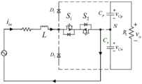
所述VIENNA变型整流桥包括二极管D1、D2、电容Cp、Cn、两个反向串联的Mos管S1、S2,二极管D1阳极连接二极管D2阴极,二极管D1、D2连接点与交流电源相连,二极管D1、D2连接点连接两个反向串联的Mos管S1、S2一端,两个反向串联的Mos管S1、S2另一端分别连接电容Cp一端、电容Cn一端,电容Cp另一端、电容Cn另一端分别连接负载RL两端。The VIENNA modified rectifier bridge includes diodes D1 , D2 , capacitors Cp , Cn , two Mos tubes S1 and S2 connected in reverse series, the anode of diode D1 is connected to the cathode of diode D2 , and the diodes D1 and D2 The connection point is connected to the AC power supply, the connection points of the diodes D1 and D2 are connected to one end of the two Mos tubes S1 and S2 in reverse series, and the other ends of the two Mos tubes S1 and S2 in reverse series are respectively connected to capacitors One end of Cp , one end of the capacitor Cn , the other end of the capacitor Cp and the other end of the capacitor Cn are respectively connected to the two ends of the loadRL .
一种新型单相混合三电平整流器控制系统,包括电压电流采样电路、信号调理电路、控制电路;A novel single-phase hybrid three-level rectifier control system, comprising a voltage and current sampling circuit, a signal conditioning circuit, and a control circuit;
所述电压采样电路,用于测量负载RL两端电压,电压采样电路连接电压反馈误差放大器;The voltage sampling circuit is used to measure the voltage at both ends of the loadRL , and the voltage sampling circuit is connected to the voltage feedback error amplifier;
所述电流采样电路,用于测量单相不可控二极管整流桥输入端电流、VIENNA变型整流桥输入端电流;The current sampling circuit is used to measure the current at the input end of the single-phase uncontrollable diode rectifier bridge and the current at the input end of the VIENNA variant rectifier bridge;
所述信号调理电路,包括两套单周期控制的电路,分别连接电压采样电路、电流采样电路,电压/电流采样采回来的信号,通过信号调理电路,输出PWM波,控制Mos管的开通与关断;The signal conditioning circuit includes two sets of single-cycle control circuits, which are respectively connected to the voltage sampling circuit and the current sampling circuit, and the signals collected by the voltage/current sampling, output PWM waves through the signal conditioning circuit, and control the opening and closing of the Mos tube. break;
所述控制电路包括依次连接的误差放大器、积分复位器、比较器、SR触发器。The control circuit includes an error amplifier, an integral resetter, a comparator, and an SR flip-flop connected in sequence.
本发明一种新型单相混合三电平整流器,具有以下的优点:A novel single-phase hybrid three-level rectifier of the present invention has the following advantages:
1、由于本发明采用单周期控制算法进行控制,实现了良好的控制效果,需要的输入量少,具有更快的响应速度、快速精准的负载调整、抗干扰能力强、控制规律简单、容易实现等优点,可以实现网侧电流正弦化、单位功率因数、直流侧电压恒定。1. Because the present invention adopts a single-cycle control algorithm for control, it achieves good control effect, requires less input, has faster response speed, fast and accurate load adjustment, strong anti-interference ability, simple control law, and easy to implement. It can realize the sinusoidal current on the grid side, the unity power factor, and the constant voltage on the DC side.
2、本发明能够快速地进行电流跟踪、很强的鲁棒性、输出电压稳定、转换效率高、功率密度高、可靠性高、电流谐波含量低和功率因数高。2. The present invention is capable of fast current tracking, strong robustness, stable output voltage, high conversion efficiency, high power density, high reliability, low current harmonic content and high power factor.
3、采用单相混合三电平整流器结构,再加上采用单周期控制的算法,控制方法简单,结构简单,只需要采集输出电压和输入电流。使得系统具有很强的鲁棒性、高功率密度、高功率因数、输出电压稳定、系统可靠性高。通过本发明,与传统的单相整流器相比可大大提高电路的转换效率,应用范围广,并且采用三电平结构可大大降低功率开关管的电压应力,可节约大量的物力财力。3. The single-phase hybrid three-level rectifier structure is adopted, coupled with the single-cycle control algorithm, the control method is simple, the structure is simple, and only the output voltage and input current need to be collected. The system has strong robustness, high power density, high power factor, stable output voltage and high system reliability. Compared with the traditional single-phase rectifier, the invention can greatly improve the conversion efficiency of the circuit, and has a wide application range, and the three-level structure can greatly reduce the voltage stress of the power switch tube, saving a lot of material and financial resources.
附图说明Description of drawings
图1为本发明新型单向混合单相整流器的电路拓扑结构框图。FIG. 1 is a block diagram of the circuit topology structure of the novel unidirectional hybrid single-phase rectifier of the present invention.
图2为本发明新型单向混合单相整流器VIENNA整流桥开关模式一流向图。FIG. 2 is a flow diagram of the switching mode of the VIENNA rectifier bridge of the novel unidirectional hybrid single-phase rectifier of the present invention.
图3为本发明新型单向混合单相整流器VIENNA整流桥开关模式二流向图。FIG. 3 is a second flow diagram of the switching mode of the VIENNA rectifier bridge of the novel unidirectional hybrid single-phase rectifier of the present invention.
图4为本发明新型单向混合单相整流器VIENNA整流桥开关模式三流向图。FIG. 4 is a three-flow diagram of the switching mode of the VIENNA rectifier bridge of the novel unidirectional hybrid single-phase rectifier of the present invention.
图5为本发明新型单向混合单相整流器VIENNA整流桥开关模式四流向图。FIG. 5 is a four-flow diagram of the switching mode of the VIENNA rectifier bridge of the novel unidirectional hybrid single-phase rectifier of the present invention.
图6为本发明新型单向混合单相整流器整流器的控制电路原理图。FIG. 6 is a schematic diagram of the control circuit of the novel unidirectional hybrid single-phase rectifier rectifier of the present invention.
图7为本发明单周期控制PFC序列图。FIG. 7 is a sequence diagram of the single-cycle control PFC of the present invention.
图8(1)为本发明新型单向混合单相整流器VIENNA整流桥的第一种变化结构图。FIG. 8(1) is a structural diagram of the first variation of the VIENNA rectifier bridge of the novel unidirectional hybrid single-phase rectifier of the present invention.
图8(2)为本发明新型单向混合单相整流器VIENNA整流桥的第二种变化结构图。Figure 8(2) is a structural diagram of the second variation of the VIENNA rectifier bridge of the novel unidirectional hybrid single-phase rectifier of the present invention.
图8(3)为本发明新型单向混合单相整流器VIENNA整流桥的第三种变化结构图。FIG. 8(3) is a structural diagram of the third variation of the VIENNA rectifier bridge of the novel unidirectional hybrid single-phase rectifier of the present invention.
图8(4)为本发明新型单向混合单相整流器VIENNA整流桥的第四种变化结构图。FIG. 8(4) is a structural diagram of the fourth variation of the VIENNA rectifier bridge of the novel unidirectional hybrid single-phase rectifier of the present invention.
图8(5)为本发明新型单向混合单相整流器VIENNA整流桥的第五种变化结构图。Figure 8(5) is a structural diagram of the fifth variation of the VIENNA rectifier bridge of the novel unidirectional hybrid single-phase rectifier of the present invention.
图8(6)为本发明新型单向混合单相整流器VIENNA整流桥的第六种变化结构图。Figure 8(6) is a structural diagram of the sixth variation of the VIENNA rectifier bridge of the novel unidirectional hybrid single-phase rectifier of the present invention.
图9为本发明新型单向混合单相整流器整流器一的输入电压电流波形图。FIG. 9 is an input voltage and current waveform diagram of a novel unidirectional hybrid single-
图10为本发明新型单向混合单相整流器整流器二的输入电压电流波形图。FIG. 10 is a waveform diagram of the input voltage and current of the
图11为本发明新型单向混合单相整流器总的输入电压电流波形图。FIG. 11 is a waveform diagram of the total input voltage and current of the novel unidirectional hybrid single-phase rectifier of the present invention.
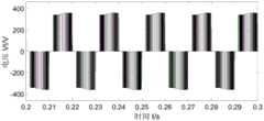
图12为本发明新型单向混合单相整流器整流器二开关管两端电压波形图。FIG. 12 is a voltage waveform diagram of the two ends of the two switching tubes of the rectifier of the novel unidirectional hybrid single-phase rectifier of the present invention.
图13为本发明新型单向混合单相整流器负载两端电压波形图。FIG. 13 is a waveform diagram of the voltage across the load of the novel unidirectional hybrid single-phase rectifier of the present invention.
图14为本发明新型单向混合单相整流器当输出控制电压变化时负载两端电压波形图。14 is a waveform diagram of the voltage across the load when the output control voltage of the novel unidirectional hybrid single-phase rectifier of the present invention changes.
图15为本发明新型单向混合单相整流器当负载功率变化时负载两端电压波形图。FIG. 15 is a waveform diagram of the voltage across the load of the novel unidirectional hybrid single-phase rectifier of the present invention when the load power changes.
具体实施方式Detailed ways
一种新型单相混合三电平整流器,包括单相不可控二极管整流桥、滤波器、VIENNA变型整流桥,所述单相不可控二极管整流桥包括二极管D3、D4、D4、D5、D6连接构成的整流部分,整流部分连接电感L1一端、电感L2一端,电感L1另一端连接二极管D7阳极、开关管SFa漏极,电感L2另一端连接开关管SFa源极、二极管D8阴极,二极管D7阴极、二极管D8阳极分别与负载RL两端。A new type of single-phase hybrid three-level rectifier, including single-phase uncontrollable diode rectifier bridge, filter, VIENNA variant rectifier bridge, the single-phase uncontrollable diode rectifier bridge includes diodes D3 , D4 , D4 , D5 ,D6 is connected to form the rectifier part, the rectifier part is connected toone end of the inductor L1,one end of the inductor L2, the other end of the inductor L1 is connected to the anode of the diode D7, the drain of the switchSFa , the other end of the inductorL2 is connected to the switchSFasource The pole, the cathode of the diode D8, the cathode of the diode D7, the anode of the diode D8 are respectively connected to the two ends of the loadRL .
所述滤波器包括滤波电感L,滤波电感L串联在交流电源和VIENNA变型整流桥之间;The filter includes a filter inductor L, and the filter inductor L is connected in series between the AC power supply and the VIENNA variant rectifier bridge;
所述VIENNA变型整流桥包括二极管D1、D2、电容Cp、Cn、两个反向串联的Mos管S1、S2,二极管D1阳极连接二极管D2阴极,二极管D1、D2连接点与交流电源相连,二极管D1、D2连接点连接两个反向串联的Mos管S1、S2一端,两个反向串联的Mos管S1、S2另一端分别连接电容Cp一端、电容Cn一端,电容Cp另一端、电容Cn另一端分别连接负载RL两端。The VIENNA variant rectifier bridge includes diodes D1 , D2 , capacitors Cp , Cn , two Mos tubes S1 and S2 connected in reverse series, the anode of diode D1 is connected to the cathode of diode D2 , and the diodes D1 and D2 The connection point is connected to the AC power supply, the connection points of the diodes D1 and D2 are connected to one end of the two Mos tubes S1 and S2 in reverse series, and the other ends of the two Mos tubes S1 and S2 in reverse series are respectively connected to capacitors One end of Cp , one end of the capacitor Cn , the other end of the capacitor Cp and the other end of the capacitor Cn are respectively connected to the two ends of the loadRL .
本发明提出的一种新型单向混合单相整流器,主要包括两个整流桥,其中一个为不控整流,另一个为VIENNA整流,两者可实现功率按比例分配。A novel unidirectional hybrid single-phase rectifier proposed by the present invention mainly includes two rectifier bridges, one of which is uncontrolled rectification and the other is VIENNA rectifier, and the power can be distributed proportionally between the two.
为更好地理解本发明内容,以下结合图1的结构框图对本发明的具体实施方式进行详细说明。In order to better understand the content of the present invention, the specific embodiments of the present invention will be described in detail below with reference to the structural block diagram of FIG. 1 .
如图1所示,该电路为混合整流电路,由两个整流器并联使用。在普通的不控整流桥后接一个boost电路,其主要作用为让两个整流器电压匹配并对单相不可控二极管整流桥进行功率因数校准,这里采用的控制策略为单周期控制的方法。另一个为VIENNA变型整流桥,其由两个二极管和两个Mos管组成。图1中,vin为交流电源的输出电压,iin为交流电源的输出电流,i1为流入整流器二的电流,i2为流入整流器一的电流,vo为电阻负载两端的电压,vm为输出电压的误差信号。As shown in Figure 1, the circuit is a hybrid rectifier circuit, which is used in parallel by two rectifiers. A boost circuit is connected behind the ordinary uncontrolled rectifier bridge, and its main function is to match the voltages of the two rectifiers and perform power factor calibration of the single-phase uncontrollable diode rectifier bridge. The control strategy used here is the single-cycle control method. The other is the VIENNA variant rectifier bridge, which consists of two diodes and two Mos tubes. In Figure 1, vin is the output voltage of the AC power supply, iin is the output current of the AC power supply, i1 is the current flowing into the second rectifier, i2 is the current flowing into the first rectifier, vo is the voltage across the resistive load, vm is the error signal of the output voltage.
对于VIENNA变型整流桥,在市电正负半周,它有四种开关模式。For the VIENNA variant rectifier bridge, it has four switching modes in the positive and negative half cycles of the mains.
开关模式一,其如图2所示。此时为市电的正半周,开关管S1导通,电流经过电感L,开关管S1,最后经过S2的体二极管流回。此过程电感L储能,负载由电容CpCn供电。Switch mode one, which is shown in Figure 2. At this time, it is the positivehalf cycle of the mains, the switch tube S1 is turnedon , the current flows through the inductor L, the switch tube S1, and finally flows back through the body diodeof S2. In this process, the inductor L stores energy, and the load is powered by the capacitor Cp Cn .
开关模式二,其如图3所示。此时为市电的正半周,开关管S1S2均不导通,电流经过电感L,二极管D1,最后经过电容Cp流回。此过程市电和电感L同时给负载供电,电容Cp充电。Switching mode two, which is shown in Figure 3. At this time, it is the positive half cycle of the commercial power, and the switches S1 and S2 are not conducting, and the current flows back through the inductor L, the diode D1 , and finally through the capacitor Cp . In this process, the mains and the inductor L supply power to the load at the same time, and the capacitor Cp is charged.
开关模式三,其如图4所示。此时为市电的负半周,开关管S2导通,电流经过开关管S2,S1的体二极管,最后经过电感L流回。此过程电感L储能,负载由电容CpCn供电。Switch mode three, which is shown in Figure 4. At this time, it is the negativehalf cycle of the mains, the switch S2 is turnedon , the current flows through the body diodesof the switches S2 and S1, and finally flows back through the inductor L. In this process, the inductor L stores energy, and the load is powered by the capacitor Cp Cn .
开关模式四,其如图5所示。此时为市电的负半周,开关管S1S2均不导通,电流经过电容Cp,二极管D2,最后经过电感L流回。此过程市电和电感L同时给负载供电,电容Cn充电。Switch mode four, which is shown in Figure 5. At this time, it is the negative half cycle of the commercial power, the switches S1 and S2 are not conducting, the current flows through the capacitor Cp , the diode D2 , and finally flows back through the inductor L. In this process, the mains and the inductor L supply power to the load at the same time, and the capacitor Cn is charged.
图6所示为整流器的控制电路原理图。控制方法采用单周期控制,其主要由四部分组成,首先为一个误差放大器,紧接着经过一个积分复位器,然后为比较器,其输出送至SR触发器。Figure 6 shows the schematic diagram of the control circuit of the rectifier. The control method adopts single-cycle control, which is mainly composed of four parts. First, it is an error amplifier, followed by an integral reset device, and then a comparator, and its output is sent to the SR flip-flop.
所述单周期控制,其主要控制过程如下:在稳态下,输出电压vo为恒定值,通过电压反馈网络得到与vo成正比的误差信号vm;经快速积分器得到vint,同时将vm和vint送入减法器,得到电流控制基准信号Vc=Vm-Vint;每个开个周期伊始,由时钟将触发器触发,开关管导通,电感储能,电感电流上升,将它与Vc一起送入比较器,当i=Vc时,比较器翻转,触发器复位,开关管光断,电感电流下降,同时积分器复位,当下一个时钟信号到来时,开关管重新导通,开始下一个周期的调制。The single-cycle control, its main control process is as follows: in steady state, the output voltage vo is a constant value, the error signal vm proportional to vo is obtained through the voltage feedback network; vint is obtained through the fast integrator, and at the same time Send vm and vint to the subtractor to obtain the current control reference signal Vc =Vm -Vint ; at the beginning of each cycle, the trigger is triggered by the clock, the switch is turned on, the inductor stores energy, and the inductor current Rise, send it to the comparator together with Vc , when i=Vc , the comparator flips, the flip-flop is reset, the switch tube is light-off, the inductor current drops, and the integrator is reset, and when the next clock signal comes, the switch The tube is turned on again and the modulation of the next cycle begins.
结合图7的单周期控制PFC控制序列图,可以更清楚地对单周期的控制过程进行理解。可以看出当开关管导通时,电流逐渐上升,而调制电压减去积分器输出的电压得到的值逐渐减小,但两者相等时,触发器翻转,积分器清零,开关管关闭电流又开始下降等待下一个周期的到来。Combined with the single-cycle control PFC control sequence diagram of FIG. 7 , the single-cycle control process can be more clearly understood. It can be seen that when the switch is turned on, the current gradually increases, and the value obtained by subtracting the voltage output by the integrator from the modulation voltage gradually decreases, but when the two are equal, the flip-flop flips, the integrator is cleared, and the switch turns off the current. It starts to fall again and waits for the next cycle to come.
结合图1,系统的仿真参数为:交流电源频率为50Hz,有效值位220V,输出直流电压vo为700V,电阻负载为50Ω,滤波电感为6mH,滤波电容Cp=Cn=2200μF,升压电感为6mH,开关频率为12KHz。Combined with Fig. 1, the simulation parameters of the system are: the AC power frequency is 50Hz, the effective value is 220V, the output DC voltage vo is 700V, the resistance load is 50Ω, the filter inductance is 6mH, the filter capacitor Cp = Cn = 2200μF, and the The piezoelectric inductance is 6mH, and the switching frequency is 12KHz.
系统的工作过程是:输出电压采样送入误差放大器,得到误差信号,这里也可以增加一个电压PI控制器,使得直流侧电压能快速收敛并稳定在期望值附近。经过比较器比较后,然后经过触发器产生门控信号,驱动Mos管的开通和关断,使得电流按正弦规率变化并与输入电压同相位。这里两个整流器由两个独立的门控信号控制,整流器二的两个Mos管由同一个信号控制。两个整流器经过单周期控制后,其输入电流都正弦化,最终是的网侧输入电流i正弦化。这里还可以通过改变输入电流所乘的系数可以实现两个整流器的功率分配。The working process of the system is: the output voltage is sampled and sent to the error amplifier to obtain the error signal. A voltage PI controller can also be added here, so that the DC side voltage can quickly converge and stabilize near the desired value. After the comparator is compared, the gate control signal is generated through the trigger to drive the Mos tube to be turned on and off, so that the current changes according to the sinusoidal rate and is in phase with the input voltage. Here, the two rectifiers are controlled by two independent gating signals, and the two Mos tubes of rectifier two are controlled by the same signal. After the two rectifiers are controlled in a single cycle, their input currents are sinusoidal, and finally the grid-side input current i is sinusoidal. Here, the power distribution of the two rectifiers can also be achieved by changing the factor by which the input current is multiplied.
图9~图15为本发明在Simulink中仿真得到的。首先图9~图11,此三个波形分别为整流器一、二以及交流电源的输入电压电流波形,可以看出不管是哪个波形其正弦化程度都很高,且功率因数高,电压电流几乎同相位。Figures 9 to 15 are obtained by simulation in Simulink of the present invention. First of all, as shown in Fig. 9 to Fig. 11, the three waveforms are the input voltage and current waveforms of the
图12为整流器二开关管两端电压波形图,可以看出其电压正负交替,且几乎对称,三电平效果好,两电容电压基本平衡。所述三电平是输出端电位有
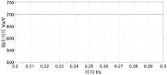
图13为整流器稳定时输出电压波形,其近似一条直线,几乎等于设定输出电压值,可见稳定性好。Figure 13 shows the output voltage waveform when the rectifier is stable, which is approximately a straight line, almost equal to the set output voltage value, showing good stability.
图14为当在0.2s时电压设定值从700跳变到740时的输出电压波形,在0.06s后电压基本稳定了。Figure 14 shows the output voltage waveform when the voltage setting value jumps from 700 to 740 at 0.2s, and the voltage is basically stable after 0.06s.
而图15为当负载加重一倍然后又恢复时的输出电压波形,可以看出其不管是加重还是减轻均能在四个周期内达到稳定。从这两幅图可以看出本发明的稳定性好,具有很强的鲁棒性。Figure 15 shows the output voltage waveform when the load is doubled and then resumed. It can be seen that it can stabilize within four cycles regardless of whether the load is increased or decreased. It can be seen from these two figures that the present invention has good stability and strong robustness.
本发明专利的保护范围不只是局限与上面介绍的结构,本发明还提出了其它五种变结构还有任何可轻易想到的变化或替换均处在本发明的保护范围内,并且此类拓扑还可推广到三相整流器中。具体结构如图8所示。可以看出此六种结构其最基本的原理都是形成一个双向流通的通道,通过改变二极管和开关管的排布来实现。至于其流通顺序以及开关管开通关断,基本和如上分析类似,此处不再做具体分析。The protection scope of the patent of the present invention is not only limited to the structure described above, the present invention also proposes other five variable structures and any changes or replacements that can be easily imagined are all within the protection scope of the present invention, and this type of topology also Can be extended to three-phase rectifiers. The specific structure is shown in Figure 8. It can be seen that the most basic principle of these six structures is to form a bidirectional flow channel, which is realized by changing the arrangement of diodes and switch tubes. As for the flow sequence and the on-off of the switch tube, it is basically similar to the above analysis, and no specific analysis will be made here.
Claims (2)
Translated fromChinesePriority Applications (1)
| Application Number | Priority Date | Filing Date | Title |
|---|---|---|---|
| CN201711420886.5ACN107896069B (en) | 2017-12-25 | 2017-12-25 | Novel single-phase mixed three-level rectifier |
Applications Claiming Priority (1)
| Application Number | Priority Date | Filing Date | Title |
|---|---|---|---|
| CN201711420886.5ACN107896069B (en) | 2017-12-25 | 2017-12-25 | Novel single-phase mixed three-level rectifier |
Publications (2)
| Publication Number | Publication Date |
|---|---|
| CN107896069A CN107896069A (en) | 2018-04-10 |
| CN107896069Btrue CN107896069B (en) | 2020-02-14 |
Family
ID=61808231
Family Applications (1)
| Application Number | Title | Priority Date | Filing Date |
|---|---|---|---|
| CN201711420886.5AActiveCN107896069B (en) | 2017-12-25 | 2017-12-25 | Novel single-phase mixed three-level rectifier |
Country Status (1)
| Country | Link |
|---|---|
| CN (1) | CN107896069B (en) |
Families Citing this family (17)
| Publication number | Priority date | Publication date | Assignee | Title |
|---|---|---|---|---|
| US10944319B2 (en)* | 2018-11-30 | 2021-03-09 | Schneider Electric It Corporation | Flying battery with AC switch PFC front end for ups |
| CN109925050B (en)* | 2019-03-07 | 2021-06-22 | 南京理工大学 | Circuit topology and control method of electrosurgical generator with high dynamic characteristics |
| CN110299859A (en)* | 2019-07-11 | 2019-10-01 | 哈尔滨理工大学 | A kind of Three phase voltage-source recitifier |
| CN111030441B (en)* | 2019-12-13 | 2021-06-04 | 三峡大学 | Single-phase power factor correction circuit based on three-tube five-level topology |
| CN111030440B (en)* | 2019-12-13 | 2021-05-04 | 三峡大学 | Single-phase two-tube five-level rectifier based on hybrid H-bridge |
| CN110880864B (en)* | 2019-12-13 | 2021-07-06 | 三峡大学 | Single-phase five-level power factor correction circuit based on hybrid H-bridge |
| CN111082680B (en)* | 2019-12-13 | 2021-05-04 | 三峡大学 | Single-phase five-level rectifier based on T-type structure |
| CN111384764A (en)* | 2020-03-23 | 2020-07-07 | 深圳供电局有限公司 | High-capacity hybrid rectification charging pile and control method thereof |
| CN111431394B (en)* | 2020-04-17 | 2024-08-02 | 广东工业大学 | A control method for a buck single-phase three-level bridgeless PFC converter system |
| CN111342684B (en)* | 2020-04-17 | 2021-08-13 | 广东工业大学 | A single-phase three-level Buck PFC rectifier and its control method |
| CN111416535B (en)* | 2020-04-24 | 2023-06-16 | 三峡大学 | Three-mode mixed single-phase five-level rectifier |
| CN111525821A (en)* | 2020-06-02 | 2020-08-11 | 哈尔滨工业大学(威海) | Novel PFC rectifier circuit |
| CN111668840A (en)* | 2020-06-08 | 2020-09-15 | 深圳供电局有限公司 | An Active Power Filter Based on Digital Resettable Integral Control |
| CN112242741B (en)* | 2020-09-25 | 2023-03-24 | 深圳供电局有限公司 | Uninterruptible power supply device and control method thereof |
| CN112701905B (en)* | 2021-01-28 | 2022-02-01 | 三峡大学 | Single-phase three-level power factor correction circuit based on pseudo totem-pole structure |
| CN113193768B (en)* | 2021-04-21 | 2022-06-14 | 三峡大学 | Back-to-back three-level rectifier with four switches in series |
| CN113985138B (en)* | 2021-09-26 | 2024-06-28 | 杭州市电力设计院有限公司 | Method for indirectly measuring and calculating boost inductance current of electric vehicle charger and pressure measuring circuit |
Citations (3)
| Publication number | Priority date | Publication date | Assignee | Title |
|---|---|---|---|---|
| CN104702133A (en)* | 2015-02-10 | 2015-06-10 | 北京信息科技大学 | Current tracking control method |
| CN106787857A (en)* | 2015-11-25 | 2017-05-31 | 纪新辉 | Unidirectional mixing three-phase voltage type rectifier |
| CN107317490A (en)* | 2017-07-03 | 2017-11-03 | 三峡大学 | A kind of dead beat prediction direct Power Control method based on three-phase Vienna rectifiers |
- 2017
- 2017-12-25CNCN201711420886.5Apatent/CN107896069B/enactiveActive
Patent Citations (3)
| Publication number | Priority date | Publication date | Assignee | Title |
|---|---|---|---|---|
| CN104702133A (en)* | 2015-02-10 | 2015-06-10 | 北京信息科技大学 | Current tracking control method |
| CN106787857A (en)* | 2015-11-25 | 2017-05-31 | 纪新辉 | Unidirectional mixing three-phase voltage type rectifier |
| CN107317490A (en)* | 2017-07-03 | 2017-11-03 | 三峡大学 | A kind of dead beat prediction direct Power Control method based on three-phase Vienna rectifiers |
Non-Patent Citations (1)
| Title |
|---|
| Analysis of High-Efficiency Three-Phase Two- and Three-Level Unidirectional Hybrid Rectifiers;Thiago B. Soeiro,Johann W. Kolar;《IEEE TRANSACTIONS ON INDUSTRIAL ELECTRONICS》;20130930;第60卷(第9期);第3589-3601页* |
Also Published As
| Publication number | Publication date |
|---|---|
| CN107896069A (en) | 2018-04-10 |
Similar Documents
| Publication | Publication Date | Title |
|---|---|---|
| CN107896069B (en) | Novel single-phase mixed three-level rectifier | |
| CN110365205B (en) | High-efficiency totem-pole bridgeless PFC rectifier control method | |
| CN101986542B (en) | PFC (power factor correction) control method with high input power factor and control circuit thereof | |
| Wei et al. | A novel bridgeless buck-boost PFC converter | |
| CN108900100B (en) | A kind of single-phase high efficiency high frequency isolated form rectifier | |
| CN105553249B (en) | Wide voltage range low voltage stress current injection type three-phase power factor correction circuit | |
| CN102130577B (en) | Window control circuit for power factor correction circuit | |
| CN110855163A (en) | A single-stage isolated three-phase rectifier and its control method | |
| CN103166489B (en) | A kind of control circuit of Three-Phase SVPWM Rectifier | |
| CN101197544A (en) | Wide Input Range Continuously Adjustable Bridgeless Buck-Boost PFC Converter | |
| CN107659138B (en) | A series-type power decoupling non-electrolytic capacitor PFC circuit and decoupling control method | |
| CN101567573A (en) | Uninterrupted power and control method thereof | |
| CN211127589U (en) | Single-stage high-frequency isolated bidirectional direct-current converter and grid-connected energy storage system | |
| CN110518818B (en) | CRM (customer relationship management) buck-flyback PFC (Power factor correction) converter controlled in fixed frequency | |
| CN102780409A (en) | Unity-power-factor buck-boost circuit | |
| CN105226986B (en) | A kind of inverter and its control method for eliminating the pulsation of input side secondary power | |
| CN203151389U (en) | Control circuit of three-phase high power factor rectifier | |
| CN109038677A (en) | A kind of efficient six switch singles grid-connected converter | |
| CN211296592U (en) | A power decoupling circuit | |
| CN219779988U (en) | A New Buck Power Factor Correction Converter | |
| CN208143107U (en) | A kind of New single-phase mixing three-level rectifier | |
| CN207304371U (en) | A kind of controlled resonant converter | |
| CN115021527B (en) | Control circuit and method of three-phase single-stage electric energy conversion device | |
| CN110289755A (en) | High Power Factor DCM Buck-Flyback PFC Converter | |
| CN201830155U (en) | Three-phase power-factor correcting switching power-supply device |
Legal Events
| Date | Code | Title | Description |
|---|---|---|---|
| PB01 | Publication | ||
| PB01 | Publication | ||
| SE01 | Entry into force of request for substantive examination | ||
| SE01 | Entry into force of request for substantive examination | ||
| GR01 | Patent grant | ||
| GR01 | Patent grant |