CN107888150B - Power amplification circuit and method for audio signal and terminal equipment - Google Patents
Power amplification circuit and method for audio signal and terminal equipmentDownload PDFInfo
- Publication number
- CN107888150B CN107888150BCN201711217730.7ACN201711217730ACN107888150BCN 107888150 BCN107888150 BCN 107888150BCN 201711217730 ACN201711217730 ACN 201711217730ACN 107888150 BCN107888150 BCN 107888150B
- Authority
- CN
- China
- Prior art keywords
- power supply
- power amplifier
- audio signal
- power
- class
- Prior art date
- Legal status (The legal status is an assumption and is not a legal conclusion. Google has not performed a legal analysis and makes no representation as to the accuracy of the status listed.)
- Active
Links
- 230000005236sound signalEffects0.000titleclaimsabstractdescription148
- 238000000034methodMethods0.000titleclaimsabstractdescription43
- 230000003321amplificationEffects0.000titleclaimsabstractdescription21
- 238000003199nucleic acid amplification methodMethods0.000titleclaimsabstractdescription21
- 238000010586diagramMethods0.000description15
- 239000010752BS 2869 Class DSubstances0.000description2
- 239000003990capacitorSubstances0.000description2
- 238000001914filtrationMethods0.000description2
- 239000004065semiconductorSubstances0.000description2
- 238000000926separation methodMethods0.000description2
- 238000006243chemical reactionMethods0.000description1
- 230000000694effectsEffects0.000description1
- 238000010438heat treatmentMethods0.000description1
Images


Classifications
- H—ELECTRICITY
- H03—ELECTRONIC CIRCUITRY
- H03F—AMPLIFIERS
- H03F1/00—Details of amplifiers with only discharge tubes, only semiconductor devices or only unspecified devices as amplifying elements
- H03F1/02—Modifications of amplifiers to raise the efficiency, e.g. gliding Class A stages, use of an auxiliary oscillation
- H03F1/0205—Modifications of amplifiers to raise the efficiency, e.g. gliding Class A stages, use of an auxiliary oscillation in transistor amplifiers
- H03F1/0211—Modifications of amplifiers to raise the efficiency, e.g. gliding Class A stages, use of an auxiliary oscillation in transistor amplifiers with control of the supply voltage or current
- H—ELECTRICITY
- H03—ELECTRONIC CIRCUITRY
- H03F—AMPLIFIERS
- H03F3/00—Amplifiers with only discharge tubes or only semiconductor devices as amplifying elements
- H03F3/181—Low-frequency amplifiers, e.g. audio preamplifiers
- H03F3/183—Low-frequency amplifiers, e.g. audio preamplifiers with semiconductor devices only
- H—ELECTRICITY
- H03—ELECTRONIC CIRCUITRY
- H03F—AMPLIFIERS
- H03F3/00—Amplifiers with only discharge tubes or only semiconductor devices as amplifying elements
- H03F3/20—Power amplifiers, e.g. Class B amplifiers, Class C amplifiers
- H03F3/21—Power amplifiers, e.g. Class B amplifiers, Class C amplifiers with semiconductor devices only
- H03F3/213—Power amplifiers, e.g. Class B amplifiers, Class C amplifiers with semiconductor devices only in integrated circuits
Landscapes
- Engineering & Computer Science (AREA)
- Power Engineering (AREA)
- Microelectronics & Electronic Packaging (AREA)
- Multimedia (AREA)
- Amplifiers (AREA)
Abstract
Description
Translated fromChinese技术领域technical field
本申请涉及终端技术领域,尤其涉及一种音频信号的功率放大电路、方法及终端设备。The present application relates to the technical field of terminals, and in particular, to a power amplifier circuit, method and terminal device for audio signals.
背景技术Background technique
功率放大电路是一种以输出较大功率为目的的放大电路,它可以驱动负载工作,如扬声器。其中,功率放大电路包括电源模块和功率放大器。电源模块用于整个功率放大电路供电;功率放大器,一般简称“功放”,是一种在给定失真率条件下,能够产生最大功率输出以驱动某一负载的放大器。A power amplifier circuit is an amplifier circuit for the purpose of outputting high power, which can drive loads such as speakers. Wherein, the power amplifier circuit includes a power module and a power amplifier. The power module is used to supply power to the entire power amplifier circuit; the power amplifier, generally referred to as "power amplifier", is an amplifier that can generate the maximum power output to drive a certain load under the condition of a given distortion rate.
目前,功率放大电路采用的功率放大器一般为D类功率放大器和AB类功率放大器。At present, the power amplifiers used in the power amplifier circuit are generally class D power amplifiers and class AB power amplifiers.
其中,D类功率放大器是一种脉冲控制的大电流开关放大器,具有高频率的特点,它的实际效率大约能够达到90%;但是D类功率放大器容易和功率放大器应用的设备上的其他信号产生干扰,从而产生杂音,因而D类功率放大器通常只能布置在靠近扬声器的位置,如此使得功率放大电路在设备中布局具有较大的局限性。Among them, the class D power amplifier is a pulse-controlled high-current switching amplifier, which has the characteristics of high frequency, and its actual efficiency can reach about 90%; but the class D power amplifier is easy to generate with other signals on the power amplifier application equipment. Therefore, the class D power amplifier can usually only be arranged close to the speaker, which makes the layout of the power amplifier circuit in the device have great limitations.
AB类功率放大器是一种抗干扰能力较好的放大器。但其效率较低,在采用AB类功率放大器时,电源模块向AB类功率放大器输入工作电压,以该工作电压产生的能量中的几乎一半能量用于电源模块中的晶体管的发热,剩余的一半能量用于AB类功率放大器对音频信号进行放大,因此AB类功率放大器在对音频信号放大时的实际效率大约只有50%。Class AB power amplifier is a kind of amplifier with better anti-interference ability. However, its efficiency is low. When a class AB power amplifier is used, the power supply module inputs the working voltage to the class AB power amplifier, and almost half of the energy generated by the working voltage is used for the heating of the transistor in the power module, and the remaining half The energy is used by the class AB power amplifier to amplify the audio signal, so the actual efficiency of the class AB power amplifier in amplifying the audio signal is only about 50%.
发明内容SUMMARY OF THE INVENTION
本申请提供一种音频信号的功率放大电路、方法及终端设备,能够在抗干扰的同时,减少功率的损耗,从而提高音频信号放大过程中的放大效率。The present application provides an audio signal power amplifying circuit, method and terminal device, which can reduce power loss while resisting interference, thereby improving the amplification efficiency in the audio signal amplifying process.
为了达到上述目的,本申请采用如下技术方案:In order to achieve the above object, the application adopts the following technical solutions:
本申请的第一方面,提供一种音频信号的功率放大电路,包括:电源模块和功率放大器。其中,功率放大器为AB类功率放大器或A类功率放大器。电源模块的输入端用于连接音频信号输入装置;电源模块的输出端与功率放大器的电源端连接,用于向功率放大器输入工作电压,并根据功率放大器的输出电压控制工作电压的绝对值大于输出电压的绝对值,且工作电压与输出电压之差的绝对值在预设范围内。功率放大器的输入端用于连接音频信号输入装置,用于根据工作电压对音频信号进行功率放大。A first aspect of the present application provides an audio signal power amplifying circuit, including: a power supply module and a power amplifier. The power amplifier is a class AB power amplifier or a class A power amplifier. The input end of the power supply module is used to connect the audio signal input device; the output end of the power supply module is connected to the power supply end of the power amplifier, and is used to input the working voltage to the power amplifier, and control the absolute value of the working voltage to be greater than the output voltage according to the output voltage of the power amplifier. The absolute value of the voltage, and the absolute value of the difference between the working voltage and the output voltage is within the preset range. The input end of the power amplifier is used for connecting an audio signal input device, and is used for power amplifying the audio signal according to the working voltage.
本申请中,由于音频信号的功率放大电路采用的是AB类功率放大器或A类功率放大器,因此具有较好的抗干扰能力;并且,由于电源模块可以通过控制向功率放大器输入的工作电压,使得该工作电压与功率放大器的输出电压之差的绝对值在预设范围内,此时电源模块产生的无用的热功率非常小,因此减少了功率的损耗,从而提高了音频信号放大过程中的放大效率。In this application, since the power amplifier circuit of the audio signal adopts a class AB power amplifier or a class A power amplifier, it has better anti-interference ability; The absolute value of the difference between the working voltage and the output voltage of the power amplifier is within a preset range, and the useless thermal power generated by the power module is very small at this time, thus reducing the power loss, thereby improving the audio signal amplification process. efficiency.
本申请的第二方面,提供一种音频信号的功率放大方法,可以应用于包括电源模块和功率放大器的音频信号的功率放大电路,电源模块的输入端与音频信号输入装置连接,电源模块的输出端与功率放大器的电源端连接,功率放大器的输入端与音频信号输入装置连接。本申请中的音频信号的功率放大方法包括:电源模块向功率放大器输入工作电压,功率放大器为AB类功率放大器或A类功率放大器;电源模块根据功率放大器的输出电压,控制工作电压的绝对值大于输出电压的绝对值,且工作电压与输出电压之差的绝对值在预设范围内,以使得功率放大器根据工作电压对音频信号进行功率放大。A second aspect of the present application provides a power amplifying method for an audio signal, which can be applied to a power amplifying circuit for an audio signal including a power supply module and a power amplifier, the input end of the power supply module is connected to an audio signal input device, and the output of the power supply module The terminal is connected with the power supply terminal of the power amplifier, and the input terminal of the power amplifier is connected with the audio signal input device. The power amplifying method of an audio signal in the present application includes: a power supply module inputs a working voltage to a power amplifier, and the power amplifier is a class AB power amplifier or a class A power amplifier; the power supply module controls the absolute value of the working voltage to be greater than the output voltage of the power amplifier The absolute value of the output voltage, and the absolute value of the difference between the working voltage and the output voltage is within a preset range, so that the power amplifier performs power amplification on the audio signal according to the working voltage.
本申请中,由于音频信号的功率放大电路采用的是AB类功率放大器或A类功率放大器,因此具有较好的抗干扰能力;并且,由于电源模块可以通过控制向功率放大器输入的工作电压,使得该工作电压与功率放大器的输出电压之差的绝对值在预设范围内,此时电源模块产生的无用的热功率非常小,因此减少了功率的损耗,从而提高了音频信号放大过程中的放大效率。In this application, since the power amplifier circuit of the audio signal adopts a class AB power amplifier or a class A power amplifier, it has better anti-interference ability; The absolute value of the difference between the working voltage and the output voltage of the power amplifier is within a preset range, and the useless thermal power generated by the power module is very small at this time, thus reducing the power loss, thereby improving the audio signal amplification process. efficiency.
本申请的第三方面,提供一种终端设备,该终端设备包括:至少一个音频信号输出装置以及如第一方面或第一方面的可能的实现方式中的音频信号的功率放大电路。其中,音频信号的功率放大电路用于驱动至少一个音频信号输出装置,以使得至少一个音频信号输出装置输出放大后的音频信号。A third aspect of the present application provides a terminal device, which includes: at least one audio signal output device and a power amplifying circuit for audio signals as in the first aspect or possible implementations of the first aspect. Wherein, the power amplifying circuit of the audio signal is used to drive at least one audio signal output device, so that the at least one audio signal output device outputs the amplified audio signal.
本申请中,终端设备不仅简化了D类功率放大器的布局,且节省了成本;并且,减少了功率的损耗,从而提高了音频信号放大过程中的放大效率。In the present application, the terminal device not only simplifies the layout of the class D power amplifier, but also saves the cost; and also reduces the power loss, thereby improving the amplification efficiency in the audio signal amplification process.
本申请的第四方面,提供一种音频信号的功率放大的装置,该音频信号的功率放大的装置包括:至少一个音频信号输出装置以及如第一方面或第一方面的可能的实现方式中的音频信号的功率放大电路。A fourth aspect of the present application provides an apparatus for power amplifying an audio signal, the apparatus for amplifying the power of an audio signal includes: at least one audio signal output apparatus and the first aspect or a possible implementation manner of the first aspect. Power amplifier circuit for audio signal.
附图说明Description of drawings
图1为本申请实施例提供的一种音频信号的功率放大电路的组成示意图;1 is a schematic diagram of the composition of a power amplifier circuit for an audio signal provided by an embodiment of the application;
图2为现有技术中的工作电压与输出电压的实例示意图;2 is a schematic diagram of an example of a working voltage and an output voltage in the prior art;
图3为本申请实施例提供的一种工作电压与输出电压的实例示意图;3 is a schematic diagram of an example of a working voltage and an output voltage provided by an embodiment of the present application;
图4为本申请实施例提供的另一种音频信号的功率放大电路的组成示意图;FIG. 4 is a schematic diagram of the composition of another audio signal power amplifying circuit provided by an embodiment of the present application;
图5为本申请实施例提供的一种第一电源支路的组成示意图;FIG. 5 is a schematic diagram of the composition of a first power supply branch according to an embodiment of the present application;
图6为本申请实施例提供的一种第一正弦波信号的实例示意图;6 is a schematic diagram of an example of a first sine wave signal provided by an embodiment of the present application;
图7为本申请实施例提供的一种第一PWM信号的实例示意图;7 is a schematic diagram of an example of a first PWM signal provided by an embodiment of the present application;
图8为本申请实施例提供的一种第二电源支路的组成示意图;FIG. 8 is a schematic diagram of the composition of a second power supply branch according to an embodiment of the present application;
图9为本申请实施例提供的第二正弦波信号的实例示意图;9 is a schematic diagram of an example of a second sine wave signal provided by an embodiment of the present application;
图10为本申请实施例提供的第二PWM信号的实例示意图;10 is a schematic diagram of an example of a second PWM signal provided by an embodiment of the application;
图11为本申请实施例提供的一种电源模块的组成示意图;FIG. 11 is a schematic diagram of the composition of a power module according to an embodiment of the application;
图12为本申请实施例提供的另一种音频信号的功率放大电路的组成示意图;12 is a schematic diagram of the composition of another audio signal power amplifying circuit provided by an embodiment of the application;
图13为本申请实施例提供的一种终端设备的结构示意图;FIG. 13 is a schematic structural diagram of a terminal device according to an embodiment of the present application;
图14为现有技术中的终端设备的实例示意图;14 is a schematic diagram of an example of a terminal device in the prior art;
图15为本申请实施例提供的一种终端设备的实例示意图;FIG. 15 is a schematic diagram of an example of a terminal device provided by an embodiment of the present application;
图16为本申请实施例提供的一种音频信号的功率放大方法的流程图;16 is a flowchart of a method for power amplifying an audio signal provided by an embodiment of the application;
图17为本申请实施例提供的另一种音频信号的功率放大方法的流程图;17 is a flowchart of another audio signal power amplifying method provided by an embodiment of the present application;
图18为本申请实施例提供的另一种音频信号的功率放大方法的流程图。FIG. 18 is a flowchart of another audio signal power amplifying method provided by an embodiment of the present application.
具体实施方式Detailed ways
下面将结合本申请实施例中的附图,对本申请实施例中的技术方案进行清楚、完整地描述,显然,所描述的实施例是本申请一部分实施例,而不是全部的实施例。基于本申请中的实施例,本领域普通技术人员在没有作出创造性劳动前提下所获得的所有其他实施例,都属于本申请保护的范围。The technical solutions in the embodiments of the present application will be clearly and completely described below with reference to the accompanying drawings in the embodiments of the present application. Obviously, the described embodiments are part of the embodiments of the present application, not all of the embodiments. Based on the embodiments in the present application, all other embodiments obtained by those of ordinary skill in the art without creative work fall within the protection scope of the present application.
本申请实施例的说明书和权利要求书中的术语“第一”和“第二”等是用于区别不同的对象,而不是用于描述对象的特定顺序。例如,第一电源支路和第二电源支路等是用于区别不同的电源支路,而不是用于描述操作指令的特定顺序。在本申请实施例的描述中,除非另有说明,“多个”的含义是指两个或两个以上。The terms "first" and "second" in the description and claims of the embodiments of the present application are used to distinguish different objects, rather than to describe a specific order of the objects. For example, the first power supply branch, the second power supply branch, etc. are used to distinguish different power supply branches, but are not used to describe a specific sequence of operation instructions. In the description of the embodiments of the present application, unless otherwise specified, the meaning of "plurality" refers to two or more.
在本申请实施例中,“示例性的”或者“例如”等词用于表示作例子、例证或说明。本申请实施例中被描述为“示例性的”或者“例如”的任何实施例或设计方案不应被解释为比其它实施例或设计方案更优选或更具优势。确切而言,使用“示例性的”或者“例如”等词旨在以具体方式呈现相关概念。In the embodiments of the present application, words such as "exemplary" or "for example" are used to represent examples, illustrations or illustrations. Any embodiments or designs described in the embodiments of the present application as "exemplary" or "such as" should not be construed as preferred or advantageous over other embodiments or designs. Rather, the use of words such as "exemplary" or "such as" is intended to present the related concepts in a specific manner.
本申请实施例提供一种音频信号的功率放大电路、方法及终端设备,可以在抗干扰的同时,减少功率的损耗,从而提高音频信号放大过程中的放大效率。Embodiments of the present application provide an audio signal power amplifying circuit, method, and terminal device, which can reduce power loss while resisting interference, thereby improving the amplification efficiency in the audio signal amplifying process.
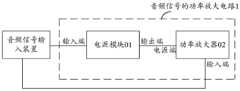
在本申请的第一种实施例中,图1示出了本申请实施例提供的一种音频信号的功率放大电路。如图1所示,该音频信号的功率放大电路1可以包括:电源模块01和功率放大器02。In the first embodiment of the present application, FIG. 1 shows an audio signal power amplifying circuit provided by the embodiment of the present application. As shown in FIG. 1 , the power amplifying
其中,电源模块01的输入端用于连接音频信号输入装置;电源模块01的输出端与功率放大器02的电源端连接,用于向功率放大器02输入工作电压,并根据功率放大器02的输出电压控制工作电压的绝对值大于输出电压的绝对值,且工作电压与输出电压之差的绝对值在预设范围内。The input terminal of the power supply module 01 is used to connect the audio signal input device; the output terminal of the power supply module 01 is connected to the power supply terminal of the power amplifier 02, and is used to input the working voltage to the power amplifier 02 and control the output voltage according to the power amplifier 02. The absolute value of the working voltage is greater than the absolute value of the output voltage, and the absolute value of the difference between the working voltage and the output voltage is within a preset range.
其中,功率放大器02可以为AB类功率放大器或A类功率放大器。功率放大器02的输入端用于连接音频信号输入装置,并用于根据工作电压对音频信号进行功率放大。The power amplifier 02 may be a class AB power amplifier or a class A power amplifier. The input end of the power amplifier 02 is used to connect the audio signal input device, and is used to power amplify the audio signal according to the working voltage.
可选的,本申请实施例中的电源模块01可以为开关电源电路、降压式变换电路或升压斩波电路。Optionally, the power module 01 in the embodiment of the present application may be a switching power supply circuit, a step-down conversion circuit, or a boost chopper circuit.
可选的,本申请实施例中的预设范围可以为0.1V~0.2V。Optionally, the preset range in this embodiment of the present application may be 0.1V to 0.2V.
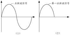
示例性的,以功率放大器为AB类功率放大器为例,以正弦波为例。现有技术中,如图2所示,电源模块的输出端向AB类功率放大器输入的工作电压为±V1,AB类功率放大器在对音频信号放大时使用的工作电压(即输出电压)为±V2,图2中的a1部分为无用的热功率,a2部分为有效功率,则在对音频信号放大时的功放效率为
本申请实施例中,如图3所示,电源模块01的输出端向AB类功率放大器输入的工作电压为±V3,AB类功率放大器的输出电压为±V2,且V3与V2之差为0.1V,图3中的a3部分(a3<a1)为无用的热功率,a2部分为有效功率,则在对音频信号放大时的功放效率为

示例性的,本申请实施例中的预设范围为0.1V时,在对音频信号放大时的功放效率最大,且不会产生失真现象。Exemplarily, when the preset range in the embodiment of the present application is 0.1V, the power amplifier efficiency when amplifying the audio signal is the highest, and no distortion phenomenon occurs.
例如,AB类功率放大器的输出电压V2=4V,输入的工作电压为V3=4.1V,则功放效率为
本申请实施例提供一种音频信号的功率放大电路,由于音频信号的功率放大电路采用的是AB类功率放大器或A类功率放大器,因此具有较好的抗干扰能力;并且,由于电源模块可以通过控制向功率放大器输入的工作电压,使得该工作电压与功率放大器的输出电压之差的绝对值在预设范围内,此时电源模块产生的无用的热功率非常小,因此减少了功率的损耗,从而提高了音频信号放大过程中的放大效率。An embodiment of the present application provides a power amplifier circuit for audio signals. Since the power amplifier circuit for audio signals adopts a class AB power amplifier or a class A power amplifier, it has better anti-interference ability; The working voltage input to the power amplifier is controlled so that the absolute value of the difference between the working voltage and the output voltage of the power amplifier is within a preset range. At this time, the useless thermal power generated by the power module is very small, thus reducing the power loss, Thus, the amplification efficiency in the audio signal amplification process is improved.
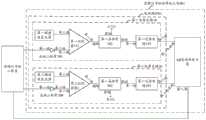
可选的,在本申请实施例的一种实现方式中,结合图1,如图4所示,示出了本申请实施例提供的另一种音频信号的功率放大电路。具体的,图4中的电源模块01可以包括第一电源支路10和第二电源支路20,功率放大器02为AB类功率放大器。Optionally, in an implementation manner of the embodiment of the present application, with reference to FIG. 1 , as shown in FIG. 4 , another audio signal power amplifying circuit provided by the embodiment of the present application is shown. Specifically, the power supply module 01 in FIG. 4 may include a first
其中,第一电源支路10的输入端用于连接音频信号输入装置,第一电源支路10的输出端与AB类功率放大器的第一电源端连接。第一电源支路10的输入端用于向AB类功率放大器输入第一工作电压,并根据AB类功率放大器的第一输出电压控制第一工作电压大于第一输出电压,且第一工作电压与第一输出电压之差的绝对值在预设范围内。The input end of the first
其中,第二电源支路20的输入端用于连接音频信号输入装置,第二电源支路20的输出端与AB类功率放大器的第二电源端连接。第二电源支路20的输入端用于向AB类功率放大器输入第二工作电压,并根据AB类功率放大器的第二输出电压控制第二工作电压的绝对值大于第二输出电压的绝对值,且第二工作电压与第二输出电压之差的绝对值在预设范围内。The input end of the second
其中,AB类功率放大器的输入端用于连接音频信号输入装置。Among them, the input end of the class AB power amplifier is used to connect the audio signal input device.
示例性的,本申请实施例中的第一电源支路10可以为正电源模块,AB类功率放大器的第一电源端可以为正电源端。第一电源支路10向AB类功率放大器输入第一工作电压+V3(即V3,V3>0),并根据AB类功率放大器的第一输出电压+V2(即V2,V2≥0)控制V3大于V2,且V3与V2之差的绝对值在预设范围内。Exemplarily, the first
例如,假设预设范围为0.1V。AB类功率放大器的第一输出电压为4V,第一电源支路10则向AB类功率放大器输入的第一工作电压为4.1V。For example, assume the preset range is 0.1V. The first output voltage of the class AB power amplifier is 4V, and the first operating voltage input by the first
示例性的,本申请实施例中的第二电源支路20可以为负电源模块,AB类功率放大器的第二电源端可以为负电源端。第二电源支路20向AB类功率放大器输入第二工作电压-V3,并根据AB类功率放大器的第二输出电压-V2控制-V3的绝对值大于-V2的绝对值(即V3大于V2),且-V3与-V2之差的绝对值在预设范围内。Exemplarily, the second
例如,假设预设范围为0.1V。AB类功率放大器的第二输出电压为-4V,第一电源支路10则向AB类功率放大器输入的第二工作电压为-4.1V。For example, assume the preset range is 0.1V. The second output voltage of the class AB power amplifier is -4V, and the second operating voltage input by the first
进一步的,本申请实施例中的电源模块01可以为开关电源电路。如图5所示,示出了本申请实施例提供的一种第一电源支路10。其中,第一电源支路10包括正向二极管100、第一比较器101、第一晶体管102和第一还原电路103。Further, the power supply module 01 in the embodiment of the present application may be a switching power supply circuit. As shown in FIG. 5 , a first
其中,正向二极管100的第一端用于连接音频信号输入装置,正向二极管100的第二端与第一比较器101的第一端连接,第一比较器101的第二端与第一晶体管102的栅极连接,第一晶体管102的源极与正电源电压(Volt Current Condenser,VCC)连接,第一晶体管102的漏极与第一还原电路103的第一端连接,第一还原电路103的第二端与AB类功率放大器的第一电源端连接。The first end of the forward diode 100 is used to connect the audio signal input device, the second end of the forward diode 100 is connected to the first end of the first comparator 101, and the second end of the first comparator 101 is connected to the first end of the first comparator 101. The gate of the
其中,正向二极管100,用于对音频信号进行分离处理,以得到第一音频信号。The forward diode 100 is used to separate and process the audio signal to obtain the first audio signal.
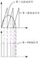
示例性的,以正弦波信号为例。如图6所示,正向二极管100对图6中的(1)所示的正弦波信号进行分离处理,得到图6中的(2)所示的第一正弦波信号。Illustratively, take a sine wave signal as an example. As shown in FIG. 6 , the forward diode 100 performs separation processing on the sine wave signal shown in (1) in FIG. 6 to obtain the first sine wave signal shown in (2) in FIG. 6 .
其中,第一比较器101,用于对第一音频信号进行比较处理,以得到第一脉宽调制(Pulse Width Modulation,PWM)信号。The first comparator 101 is configured to perform comparison processing on the first audio signal to obtain a first pulse width modulation (Pulse Width Modulation, PWM) signal.
示例性的,如图5所示,第一比较器101的第三端与第一锯齿波发生器连接,第一比较器101用于对第一音频信号和第一锯齿波发生器产生的第一锯齿波信号进行比较处理。Exemplarily, as shown in FIG. 5 , the third end of the first comparator 101 is connected to the first sawtooth wave generator, and the first comparator 101 is used to compare the first audio signal and the first signal generated by the first sawtooth wave generator. A sawtooth wave signal is compared and processed.
示例性的,如图7所示,第一比较器101将图6中的(2)所示的第一正弦波信号与第一锯齿波信号进行比较,当第一正弦波信号高于第一锯齿波信号时,记为高电平,当第一正弦波信号低于第一锯齿波信号时,记为低电平,得到如图7所示的第一PWM信号。Exemplarily, as shown in FIG. 7 , the first comparator 101 compares the first sine wave signal shown in (2) in FIG. 6 with the first sawtooth wave signal, and when the first sine wave signal is higher than the first When a sawtooth wave signal is used, it is recorded as a high level, and when the first sine wave signal is lower than the first sawtooth wave signal, it is recorded as a low level, and a first PWM signal as shown in FIG. 7 is obtained.
其中,第一晶体管102,用于对第一PWM信号进行放大处理,以得到放大的第一PWM信号;第一晶体管102,还用于根据第一输出电压控制放大的第一PWM信号的电压为第一工作电压。The
示例性的,第一晶体管102可以为金属-氧化物-半导体(Metal-Oxide-Semiconductor,MOS)管。第一晶体管102根据第一输出电压V2控制放大的第一PWM信号的电压为第一工作电压V3,V3大于V2,且V3与V2之差的绝对值在预设范围内。Exemplarily, the
本申请实施例中,第一晶体管102控制放大的第一PWM信号的电压为第一工作电压,第一工作电压大于第一输出电压,且第一工作电压与第一输出电压之差的绝对值在预设范围内,此时第一晶体管102工作在饱和区(第一晶体管102的源极和漏极之间的压降大约为0.1V),产生的无用的热功率非常小。In the embodiment of the present application, the voltage of the first PWM signal amplified by the
其中,第一还原电路103,用于对放大的第一PWM信号进行还原处理,以得到放大的第一音频信号;第一还原电路103,还用于向AB类功率放大器输入第一工作电压的放大的第一音频信号。Wherein, the first restoration circuit 103 is used to restore the amplified first PWM signal to obtain the amplified first audio signal; the first restoration circuit 103 is also used to input the first working voltage to the class AB power amplifier. The amplified first audio signal.
示例性的,第一还原电路103可以对放大的第一PWM信号进行滤波等还原处理,得到放大的第一音频信号。第一还原电路103可以包括正向二极管、电感和电容等元件。Exemplarily, the first restoration circuit 103 may perform restoration processing such as filtering on the amplified first PWM signal to obtain the amplified first audio signal. The first restoration circuit 103 may include elements such as forward diodes, inductors, and capacitors.
如图8所示,示出了本申请实施例提供的一种第二电源支路20。其中,第二电源支路20包括反向二极管200、第二比较器201、第二晶体管202和第二还原电路203。As shown in FIG. 8 , a second
其中,反向二极管200的第一端用于连接音频信号输入装置,反向二极管200的第二端与第二比较器201的第一端连接,第二比较器201的第二端与第二晶体管202的栅极连接,第二晶体管202的源极与负VCC连接,第二晶体管202的漏极与第二还原电路203的第一端连接,第二还原电路203的第二端与AB类功率放大器的第二电源端连接。The first end of the reverse diode 200 is used to connect the audio signal input device, the second end of the reverse diode 200 is connected to the first end of the second comparator 201, and the second end of the second comparator 201 is connected to the second The gate of the
其中,反向二极管200,用于对音频信号进行分离处理,以得到第二音频信号。The reverse diode 200 is used to separate and process the audio signal to obtain the second audio signal.
示例性的,以正弦波信号为例。如图9所示,反向二极管200对图6中的(1)所示的正弦波信号进行分离处理,得到如图9所示的第二正弦波信号。Illustratively, take a sine wave signal as an example. As shown in FIG. 9 , the reverse diode 200 performs separation processing on the sine wave signal shown in (1) in FIG. 6 to obtain the second sine wave signal shown in FIG. 9 .
其中,第二比较器201,用于对第二音频信号进行比较处理,以得到第二PWM信号。The second comparator 201 is used for comparing and processing the second audio signal to obtain the second PWM signal.
示例性的,如图8所示,第二比较器201的第三端与第二锯齿波发生器连接,第二比较器201用于对第二音频信号和第二锯齿波发生器产生的第二锯齿波信号进行比较处理。Exemplarily, as shown in FIG. 8 , the third end of the second comparator 201 is connected to the second sawtooth wave generator, and the second comparator 201 is used to compare the second audio signal and the first signal generated by the second sawtooth wave generator. The two sawtooth wave signals are compared and processed.
示例性的,如图10所示,第二比较器201将图9所示的第二正弦波信号与第二锯齿波信号进行比较,当第二正弦波信号高于第二锯齿波信号时,记为高电平,当第二正弦波信号低于第二锯齿波信号时,记为低电平,得到如图10所示的第二PWM信号。Exemplarily, as shown in FIG. 10 , the second comparator 201 compares the second sine wave signal shown in FIG. 9 with the second sawtooth wave signal, and when the second sine wave signal is higher than the second sawtooth wave signal, It is marked as a high level, and when the second sine wave signal is lower than the second sawtooth wave signal, it is marked as a low level, and a second PWM signal as shown in FIG. 10 is obtained.
其中,第二晶体管202,用于对第二PWM信号进行放大处理,以得到放大的第二PWM信号;第二晶体管202,还用于根据第二输出电压控制放大的第二PWM信号的电压为第二工作电压。The
示例性的,第二晶体管202可以为MOS管。第二晶体管202根据第二输出电压-V2控制放大的第二PWM信号的电压为第二工作电压-V3,-V3的绝对值大于-V2的绝对值,且-V3与-V2之差的绝对值在预设范围内。Exemplarily, the
本申请实施例中,第二晶体管202控制放大的第二PWM信号的电压为第二工作电压,第二工作电压的绝对值大于第二输出电压的绝对值,且第二工作电压与第二输出电压之差的绝对值在预设范围内,此时第二晶体管202工作在饱和区(第二晶体管202的源极和漏极之间的压降大约为0.1V),产生的无用的热功率非常小。In the embodiment of the present application, the voltage of the second PWM signal amplified by the
其中,第二还原电路203,用于对放大的第二PWM信号进行还原处理,以得到放大的第二音频信号;第二还原电路203,还用于向AB类功率放大器输入第二工作电压的放大的第二音频信号。Wherein, the second restoration circuit 203 is used to restore the amplified second PWM signal to obtain the amplified second audio signal; the second restoration circuit 203 is also used to input the second working voltage to the class AB power amplifier. Amplified second audio signal.
示例性的,第二还原电路203可以对放大的第二PWM信号进行滤波等还原处理,得到放大的第二音频信号。第二还原电路203可以包括反向二极管、电感和电容等元件。Exemplarily, the second restoration circuit 203 may perform restoration processing such as filtering on the amplified second PWM signal to obtain the amplified second audio signal. The second restoration circuit 203 may include elements such as reverse diodes, inductors, and capacitors.
本申请实施例中,结合图5和图8,如图11所示,示出了本申请实施例提供的一种电源模块01。其中,电源模块01包括第一电源支路10和第二电源支路20。第一电源支路10包括正向二极管100、第一比较器101、第一晶体管102和第一还原电路103。第二电源支路20包括反向二极管200、第二比较器201、第二晶体管202和第二还原电路203。In the embodiment of the present application, with reference to FIG. 5 and FIG. 8 , as shown in FIG. 11 , a power module 01 provided by the embodiment of the present application is shown. The power supply module 01 includes a first
其中,正向二极管100的第一端用于连接音频信号输入装置,正向二极管100的第二端与第一比较器101的第一端连接,第一比较器101的第二端与第一晶体管102的栅极连接,第一比较器101的第三端与第一锯齿波发生器连接,第一晶体管102的源极与正VCC连接,第一晶体管102的漏极与第一还原电路103的第一端连接,第一还原电路103的第二端用于连接AB类功率放大器的第一电源端。The first end of the forward diode 100 is used to connect the audio signal input device, the second end of the forward diode 100 is connected to the first end of the first comparator 101, and the second end of the first comparator 101 is connected to the first end of the first comparator 101. The gate of the
其中,反向二极管200的第一端用于连接音频信号输入装置,反向二极管200的第二端与第二比较器201的第一端连接,第二比较器201的第二端与第二晶体管202的栅极连接,第二比较器201的第三端与第二锯齿波发生器连接,第二晶体管202的源极与负VCC连接,第二晶体管202的漏极与第二还原电路203的第一端连接,第二还原电路203的第二端用于连接AB类功率放大器的第二电源端。The first end of the reverse diode 200 is used to connect the audio signal input device, the second end of the reverse diode 200 is connected to the first end of the second comparator 201, and the second end of the second comparator 201 is connected to the second The gate of the
本申请实施例中,结合图4和图11,如图12所示,示出了本申请实施例提供的另一种音频信号的功率放大电路。其中,音频信号的功率放大电路1包括电源模块01和AB功率放大器。电源模块01包括第一电源支路10和第二电源支路20。第一电源支路10包括正向二极管100、第一比较器101、第一晶体管102和第一还原电路103。第二电源支路20包括反向二极管200、第二比较器201、第二晶体管202和第二还原电路203。In the embodiment of the present application, with reference to FIG. 4 and FIG. 11 , as shown in FIG. 12 , another audio signal power amplifying circuit provided by the embodiment of the present application is shown. The
需要说明的是,本申请实施例中的电源模块还可以为其他的开关电源模块,本申请实施例在此不作任何限制。It should be noted that, the power supply module in the embodiment of the present application may also be other switching power supply modules, and the embodiment of the present application does not make any limitation here.
需要说明的是,本申请实施例中的符号“±”表示正或负,例如输出电压为±V2表示输出电压为+V2(即V2)或为-V2。It should be noted that the symbol "±" in the embodiments of the present application means positive or negative, for example, an output voltage of ±V2 means that the output voltage is +V2 (ie V2) or -V2.
可选的,在本申请实施例的另一种实现方式中,电源模块01可以仅包括第三电源支路30,功率放大器为A类功率放大器。Optionally, in another implementation manner of the embodiment of the present application, the power supply module 01 may only include the third power supply branch 30 , and the power amplifier is a class A power amplifier.
其中,第三电源支路30的输入端用于连接音频信号输入装置,第三电源支路30的输出端与A类功率放大器的电源端连接。第三电源支路30的输入端用于向A类功率放大器输入第三工作电压,并根据A类功率放大器的第三输出电压控制第三工作电压的绝对值大于第三输出电压的绝对值,且第三工作电压与第三输出电压之差的绝对值在预设范围内。A类功率放大器的输入端用于连接音频信号输入装置。The input end of the third power supply branch 30 is used for connecting an audio signal input device, and the output end of the third power supply branch 30 is connected to the power supply end of the class A power amplifier. The input end of the third power supply branch 30 is used to input the third working voltage to the class A power amplifier, and control the absolute value of the third working voltage to be greater than the absolute value of the third output voltage according to the third output voltage of the class A power amplifier, And the absolute value of the difference between the third working voltage and the third output voltage is within a preset range. The input terminal of the class A power amplifier is used to connect the audio signal input device.
在本申请的第二种实施例中,图13示出了本申请实施例提供的一种终端设备。如图13所示,该终端设备1300可以包括:至少一个音频信号输出装置1301和音频信号的功率放大电路1。In the second embodiment of the present application, FIG. 13 shows a terminal device provided by an embodiment of the present application. As shown in FIG. 13 , the terminal device 1300 may include: at least one audio signal output device 1301 and a
其中,音频信号的功率放大电路1用于驱动至少一个音频信号输出装置1301,以使得至少一个音频信号输出装置1301输出放大后的音频信号。The
示例性的,至少一个音频信号输出装置1301可以为至少一个扬声器。Exemplarily, the at least one audio signal output device 1301 may be at least one speaker.
相较于现有技术,本申请实施例提供的终端设备中,音频信号的功率放大电路1的布局比较灵活,无需局限于扬声器附近,尤其是在终端设备包含多个(大于一个)扬声器的情况下,效果更佳突出。下面结合附图具体说明。图14和图15分别示出了现有技术中终端设备1300和本申请实施例中的终端设备1300。Compared with the prior art, in the terminal device provided by the embodiment of the present application, the layout of the
示例性的,如图14所示,现有技术中的终端设备1300在包括多个(图14中仅示出两个为例)扬声器(即扬声器1和扬声器2)时,需要相应数量的音频信号的功率放大电路(图14中的音频信号的功率放大电路2和音频信号的功率放大电路3)。其中,音频信号的功率放大电路2包括D类功率放大器1,音频信号的功率放大电路3包括D类功率放大器2,D类功率放大器1与扬声器1连接,D类功率放大器2与扬声器2连接。Exemplarily, as shown in FIG. 14 , when the terminal device 1300 in the prior art includes multiple (only two are shown in FIG. 14 as an example) speakers (ie,
示例性的,如图15所示,本申请实施例的终端设备1300在多个(图15中仅示出两个为例)扬声器(即扬声器1和扬声器2)时,可以采用一个音频信号的功率放大电路(图15中的音频信号的功率放大电路1)。其中,音频信号的功率放大电路1包括AB类功率放大器(或A类功率放大器),AB类功率放大器分别与扬声器1和扬声器2连接。Exemplarily, as shown in FIG. 15 , when the terminal device 1300 in this embodiment of the present application has multiple (only two are shown in FIG. 15 as an example) speakers (that is,
由于现有技术中,当终端设备1300包含有多个(大于一个)扬声器时,由于采用D类功率放大器时的干扰较大,D类功率放大器通常只能靠近扬声器的位置,且需要多个D类功率放大器驱动扬声器,因此终端设备1300中的D类功率放大器的布局比较复杂,且成本较高。Because in the prior art, when the terminal device 1300 includes multiple (more than one) speakers, due to the large interference when using a Class D power amplifier, the Class D power amplifier can usually only be located close to the speaker, and multiple D power amplifiers are required. The class-D power amplifier drives the speaker, so the layout of the class-D power amplifier in the terminal device 1300 is complicated and the cost is high.
而本申请实施例中,当终端设备1300包含有多个扬声器时,由于音频信号的功率放大电路1中的AB类功率放大器抗干扰能力较强,AB类功率放大器可以与位置较远的扬声器相连以驱动该扬声器,因此一个AB类功率放大器可以驱动多个扬声器,简化了功率放大器的布局,且节省了成本;并且,音频信号的功率放大电路1中的电源模块01通过控制向AB类功率放大器输入的工作电压,使得该工作电压与AB类功率放大器的输出电压之差的绝对值在预设范围内,此时电源模块01产生的无用的热功率非常小,因此减少了功率的损耗,从而提高了音频信号放大过程中的放大效率。However, in the embodiment of the present application, when the terminal device 1300 includes multiple speakers, since the class AB power amplifier in the audio signal
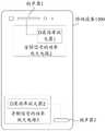
在本申请的第三种实施例中,图16示出了本申请实施例提供的一种音频信号的功率放大方法,该方法可以应用于如图1、图4和图12中任一所述的音频信号的功率放大电路。如图16所示,该音频信号的功率放大方法包括S1601和S1602:In the third embodiment of the present application, FIG. 16 shows a power amplifying method for an audio signal provided by an embodiment of the present application, and the method can be applied to any one of those described in FIG. 1 , FIG. 4 , and FIG. 12 . audio signal power amplifier circuit. As shown in Figure 16, the power amplification method of the audio signal includes S1601 and S1602:
S1601、电源模块向功率放大器输入工作电压。S1601. The power supply module inputs a working voltage to the power amplifier.
其中,功率放大器可以为AB类功率放大器或A类功率放大器。Wherein, the power amplifier may be a class AB power amplifier or a class A power amplifier.
S1602、电源模块根据功率放大器的输出电压,控制工作电压的绝对值大于输出电压的绝对值,且工作电压与输出电压之差的绝对值在预设范围内。S1602. The power module controls the absolute value of the working voltage to be greater than the absolute value of the output voltage according to the output voltage of the power amplifier, and the absolute value of the difference between the working voltage and the output voltage is within a preset range.
其中,功率放大器可以根据工作电压对音频信号进行功率放大。The power amplifier can perform power amplification on the audio signal according to the working voltage.
本申请实施例提供一种音频信号的功率放大方法,由于音频信号的功率放大电路采用的是AB类功率放大器或A类功率放大器,因此具有较好的抗干扰能力;并且,由于电源模块可以通过控制向功率放大器输入的工作电压,使得该工作电压与功率放大器的输出电压之差的绝对值在预设范围内,此时电源模块产生的无用的热功率非常小,因此减少了功率的损耗,从而提高了音频信号放大过程中的放大效率。The embodiment of the present application provides a power amplifying method for an audio signal. Since the power amplifying circuit of the audio signal adopts a class AB power amplifier or a class A power amplifier, it has better anti-interference ability; The working voltage input to the power amplifier is controlled so that the absolute value of the difference between the working voltage and the output voltage of the power amplifier is within a preset range. At this time, the useless thermal power generated by the power module is very small, thus reducing the power loss, Thus, the amplification efficiency in the audio signal amplification process is improved.
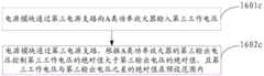
可选的,本申请实施例中,结合图16,如图17所示,上述S1601具体可以通过S1601a和S1601b实现:Optionally, in this embodiment of the present application, with reference to FIG. 16 , as shown in FIG. 17 , the foregoing S1601 may be specifically implemented through S1601a and S1601b:
S1601a、电源模块通过第一电源支路向AB类功率放大器输入第一工作电压。S1601a, the power supply module inputs the first working voltage to the class AB power amplifier through the first power supply branch.
S1601b、电源模块通过第二电源支路向AB类功率放大器输入第二工作电压。S1601b, the power supply module inputs the second working voltage to the class AB power amplifier through the second power supply branch.
相应的,本申请实施例中,结合图16,如图17所示,上述S1602具体可以通过S1602a和S1602b实现:Correspondingly, in this embodiment of the present application, with reference to FIG. 16 , as shown in FIG. 17 , the above S1602 can be specifically implemented by S1602a and S1602b:
S1602a、电源模块通过第一电源支路,根据AB类功率放大器的第一输出电压控制第一工作电压大于第一输出电压,且第一工作电压与第一输出电压之差的绝对值在预设范围内。S1602a, the power supply module controls the first operating voltage to be greater than the first output voltage according to the first output voltage of the class AB power amplifier through the first power supply branch, and the absolute value of the difference between the first operating voltage and the first output voltage is at a preset value within the range.
S1602b、电源模块通过第二电源支路,根据AB类功率放大器的第二输出电压控制第二工作电压的绝对值大于第二输出电压的绝对值,且第二工作电压与第二输出电压之差的绝对值在预设范围内。S1602b, the power supply module controls the absolute value of the second working voltage to be greater than the absolute value of the second output voltage according to the second output voltage of the class AB power amplifier through the second power supply branch, and the difference between the second working voltage and the second output voltage The absolute value of is within the preset range.
可选的,本申请实施例中,结合图16,如图18所示,上述S1601具体可以通过S1601c实现:Optionally, in this embodiment of the present application, with reference to FIG. 16 , as shown in FIG. 18 , the foregoing S1601 may be specifically implemented through S1601c:
S1601c、电源模块通过第三电源支路向A类功率放大器输入第三工作电压。S1601c, the power supply module inputs a third working voltage to the class A power amplifier through the third power supply branch.
相应的,本申请实施例中,结合图16,如图18所示,上述S1602具体可以通过S1602c实现:Correspondingly, in this embodiment of the present application, with reference to FIG. 16 , as shown in FIG. 18 , the above S1602 can be specifically implemented by S1602c:
S1602c、电源模块通过第三电源支路,根据A类功率放大器的第三输出电压控制第三工作电压的绝对值大于第三输出电压的绝对值,且第三工作电压与第三输出电压之差的绝对值在预设范围内。S1602c, the power supply module controls the absolute value of the third working voltage to be greater than the absolute value of the third output voltage according to the third output voltage of the class A power amplifier through the third power supply branch, and the difference between the third working voltage and the third output voltage The absolute value of is within the preset range.
需要说明的是,本申请实施例提供的音频信号的功率放大方法中的相关方法步骤的具体描述,可以参考本申请实施例中的音频信号的功率放大电路的相关描述,此处不再赘述。It should be noted that, for the specific description of the related method steps in the audio signal power amplifying method provided by the embodiment of the present application, reference may be made to the related description of the audio signal power amplifying circuit in the embodiment of the present application, which will not be repeated here.
需要说明的是,在本申请实施例中,术语“包括”、“包含”或者其任何其他变体意在涵盖非排他性的包含,从而使得包括一系列要素的过程、方法、物品或者装置不仅包括那些要素,而且还包括没有明确列出的其他要素,或者是还包括为这种过程、方法、物品或者装置所固有的要素。在没有更多限制的情况下,由语句“包括一个……”限定的要素,并不排除在包括该要素的过程、方法、物品或者装置中还存在另外的相同要素。It should be noted that, in the embodiments of the present application, the terms "comprising", "comprising" or any other variations thereof are intended to cover non-exclusive inclusion, so that a process, method, article or device including a series of elements not only includes Those elements, but also other elements not expressly listed or inherent to such a process, method, article or apparatus. Without further limitation, an element qualified by the phrase "comprising a..." does not preclude the presence of additional identical elements in a process, method, article or apparatus that includes the element.
通过以上的实施方式的描述,本领域的技术人员可以清楚地了解到上述实施例方法可借助软件加必需的通用硬件平台的方式来实现,当然也可以通过硬件,但很多情况下前者是更佳的实施方式。基于这样的理解,本申请的技术方案本质上或者说对现有技术做出贡献的部分可以以软件产品的形式体现出来,该计算机软件产品存储在一个存储介质(如ROM/RAM、磁碟、光盘)中,包括若干指令用以使得一台终端(可以是手机,计算机,服务器,空调器,或者网络设备等)执行本申请各个实施例所述的方法。From the description of the above embodiments, those skilled in the art can clearly understand that the method of the above embodiment can be implemented by means of software plus a necessary general hardware platform, and of course can also be implemented by hardware, but in many cases the former is better implementation. Based on this understanding, the technical solution of the present application can be embodied in the form of a software product in essence or in a part that contributes to the prior art, and the computer software product is stored in a storage medium (such as ROM/RAM, magnetic disk, CD-ROM), including several instructions to make a terminal (which may be a mobile phone, a computer, a server, an air conditioner, or a network device, etc.) execute the methods described in the various embodiments of this application.
上面结合附图对本申请的实施例进行了描述,但是本申请并不局限于上述的具体实施方式,上述的具体实施方式仅仅是示意性的,而不是限制性的,本领域的普通技术人员在本申请的启示下,在不脱离本申请宗旨和权利要求所保护的范围情况下,还可做出很多形式,均属于本申请的保护之内。The embodiments of the present application have been described above in conjunction with the accompanying drawings, but the present application is not limited to the above-mentioned specific embodiments, which are merely illustrative rather than restrictive. Under the inspiration of this application, without departing from the scope of protection of the purpose of this application and the claims, many forms can be made, which all fall within the protection of this application.
Claims (9)
Translated fromChinesePriority Applications (1)
| Application Number | Priority Date | Filing Date | Title |
|---|---|---|---|
| CN201711217730.7ACN107888150B (en) | 2017-11-28 | 2017-11-28 | Power amplification circuit and method for audio signal and terminal equipment |
Applications Claiming Priority (1)
| Application Number | Priority Date | Filing Date | Title |
|---|---|---|---|
| CN201711217730.7ACN107888150B (en) | 2017-11-28 | 2017-11-28 | Power amplification circuit and method for audio signal and terminal equipment |
Publications (2)
| Publication Number | Publication Date |
|---|---|
| CN107888150A CN107888150A (en) | 2018-04-06 |
| CN107888150Btrue CN107888150B (en) | 2020-06-30 |
Family
ID=61775861
Family Applications (1)
| Application Number | Title | Priority Date | Filing Date |
|---|---|---|---|
| CN201711217730.7AActiveCN107888150B (en) | 2017-11-28 | 2017-11-28 | Power amplification circuit and method for audio signal and terminal equipment |
Country Status (1)
| Country | Link |
|---|---|
| CN (1) | CN107888150B (en) |
Citations (5)
| Publication number | Priority date | Publication date | Assignee | Title |
|---|---|---|---|---|
| CN2796245Y (en)* | 2005-06-10 | 2006-07-12 | 李达标 | Power amplication circuit for power output wave form capable of automatic tracking input audio frequency signal wave form |
| CN203491978U (en)* | 2013-06-27 | 2014-03-19 | 快捷半导体(苏州)有限公司 | Output stage circuit, class AB amplifier and electronic device |
| US9220067B2 (en)* | 2011-05-02 | 2015-12-22 | Rf Micro Devices, Inc. | Front end radio architecture (FERA) with power management |
| CN106817094A (en)* | 2017-01-19 | 2017-06-09 | 中国科学院上海高等研究院 | A kind of radio frequency low-noise amplifier and its implementation |
| JP2018107974A (en)* | 2016-12-27 | 2018-07-05 | パナソニックIpマネジメント株式会社 | Switching power supply device and audio device |
- 2017
- 2017-11-28CNCN201711217730.7Apatent/CN107888150B/enactiveActive
Patent Citations (5)
| Publication number | Priority date | Publication date | Assignee | Title |
|---|---|---|---|---|
| CN2796245Y (en)* | 2005-06-10 | 2006-07-12 | 李达标 | Power amplication circuit for power output wave form capable of automatic tracking input audio frequency signal wave form |
| US9220067B2 (en)* | 2011-05-02 | 2015-12-22 | Rf Micro Devices, Inc. | Front end radio architecture (FERA) with power management |
| CN203491978U (en)* | 2013-06-27 | 2014-03-19 | 快捷半导体(苏州)有限公司 | Output stage circuit, class AB amplifier and electronic device |
| JP2018107974A (en)* | 2016-12-27 | 2018-07-05 | パナソニックIpマネジメント株式会社 | Switching power supply device and audio device |
| CN106817094A (en)* | 2017-01-19 | 2017-06-09 | 中国科学院上海高等研究院 | A kind of radio frequency low-noise amplifier and its implementation |
Also Published As
| Publication number | Publication date |
|---|---|
| CN107888150A (en) | 2018-04-06 |
Similar Documents
| Publication | Publication Date | Title |
|---|---|---|
| US9742357B2 (en) | Audio system having an improved efficiency and extended operation time | |
| US8149061B2 (en) | Class H amplifier | |
| Hassan et al. | A CMOS dual-switching power-supply modulator with 8% efficiency improvement for 20MHz LTE Envelope Tracking RF power amplifiers | |
| US9853602B2 (en) | Adaptive tracking rail audio amplifier | |
| CN101588125B (en) | Power-supply apparatus and control method, power amplifying device | |
| JP2016521102A (en) | Envelope tracker with variable boost power supply voltage | |
| CN102270966A (en) | Two stage doherty amplifier | |
| CN101540587A (en) | Audio power amplifier | |
| US20160276993A1 (en) | Power amplifying device | |
| US8466743B2 (en) | Ground-referenced common-mode amplifier circuit and related method | |
| US8686789B2 (en) | Transient signal suppression for a class-D audio amplifier arrangement | |
| Xiong et al. | Feed-forwarding the output voltage to improve efficiency for envelope-tracking power supply based on a switch-linear hybrid scheme | |
| CN101557202B (en) | High power D-type power amplifier | |
| CN102474224A (en) | Amplifier stage | |
| CN114531117A (en) | Common-mode voltage dynamic modulation circuit and method and class D audio power amplifier | |
| CN107888150B (en) | Power amplification circuit and method for audio signal and terminal equipment | |
| US11398802B2 (en) | Common mode voltage controller for self-boosting push pull amplifier | |
| EP1787386A1 (en) | An amplifier apparatus and method | |
| CN204408277U (en) | Power amplifier | |
| US9236839B2 (en) | Class-G amplifier and audio system employing the amplifier | |
| TW202228385A (en) | Single-stage boost class-d amplifier | |
| US11444577B2 (en) | Boost amplifier | |
| CN104639070B (en) | Integrated circuit and user terminal | |
| CN201307845Y (en) | Driving circuit | |
| CN114793095A (en) | Single Stage Boost Class D Amplifier |
Legal Events
| Date | Code | Title | Description |
|---|---|---|---|
| PB01 | Publication | ||
| PB01 | Publication | ||
| SE01 | Entry into force of request for substantive examination | ||
| SE01 | Entry into force of request for substantive examination | ||
| GR01 | Patent grant | ||
| GR01 | Patent grant |