CN107886573B - A three-dimensional finite element mesh generation method for slopes under complex geological conditions - Google Patents
A three-dimensional finite element mesh generation method for slopes under complex geological conditionsDownload PDFInfo
- Publication number
- CN107886573B CN107886573BCN201711189215.2ACN201711189215ACN107886573BCN 107886573 BCN107886573 BCN 107886573BCN 201711189215 ACN201711189215 ACN 201711189215ACN 107886573 BCN107886573 BCN 107886573B
- Authority
- CN
- China
- Prior art keywords
- finite element
- dimensional
- grid
- mesh
- nodes
- Prior art date
- Legal status (The legal status is an assumption and is not a legal conclusion. Google has not performed a legal analysis and makes no representation as to the accuracy of the status listed.)
- Active
Links
Images


Classifications
- G—PHYSICS
- G06—COMPUTING OR CALCULATING; COUNTING
- G06T—IMAGE DATA PROCESSING OR GENERATION, IN GENERAL
- G06T17/00—Three dimensional [3D] modelling, e.g. data description of 3D objects
- G06T17/05—Geographic models
- G—PHYSICS
- G06—COMPUTING OR CALCULATING; COUNTING
- G06F—ELECTRIC DIGITAL DATA PROCESSING
- G06F30/00—Computer-aided design [CAD]
- G06F30/20—Design optimisation, verification or simulation
- G06F30/23—Design optimisation, verification or simulation using finite element methods [FEM] or finite difference methods [FDM]
- G—PHYSICS
- G06—COMPUTING OR CALCULATING; COUNTING
- G06T—IMAGE DATA PROCESSING OR GENERATION, IN GENERAL
- G06T17/00—Three dimensional [3D] modelling, e.g. data description of 3D objects
- G06T17/30—Polynomial surface description
Landscapes
- Engineering & Computer Science (AREA)
- Physics & Mathematics (AREA)
- Theoretical Computer Science (AREA)
- Geometry (AREA)
- General Physics & Mathematics (AREA)
- Software Systems (AREA)
- Computer Graphics (AREA)
- Algebra (AREA)
- General Engineering & Computer Science (AREA)
- Mathematical Analysis (AREA)
- Mathematical Optimization (AREA)
- Mathematical Physics (AREA)
- Pure & Applied Mathematics (AREA)
- Evolutionary Computation (AREA)
- Computer Hardware Design (AREA)
- Remote Sensing (AREA)
- Management, Administration, Business Operations System, And Electronic Commerce (AREA)
- Processing Or Creating Images (AREA)
Abstract
Description
Translated fromChinese技术领域technical field
本发明涉及一种三维有限元网格生成方法,特别涉及一种复杂地质条件下边坡三维有限元网格生成方法,属于水利工程及岩土工程领域。The invention relates to a method for generating a three-dimensional finite element grid, in particular to a method for generating a three-dimensional finite element grid of a slope under complex geological conditions, and belongs to the fields of hydraulic engineering and geotechnical engineering.
背景技术Background technique
近年来,随着我国西南地区水利工程建设的发展,随之带来了众多高边坡问题,岩石边坡是否安全稳定影响到工程本身的正常运行,岩体边坡稳定分析与评价已经成为岩土工程领域的热点问题。In recent years, with the development of water conservancy projects in southwest my country, many high slope problems have been brought along. Whether the rock slope is safe and stable affects the normal operation of the project itself. The analysis and evaluation of rock slope stability has become a Hot issues in the field of civil engineering.
通常采用有限元分析方法(FEM)进行工程结构计算与分析,其中有限元网格的质量决定了数值计算的精度与速度。但是,有限元网格生成过程复杂、困难,特别是我国西南地区山地众多,地质条件复杂,三维有限元网格划分难度极大,常常需要多次返工和模型处理,网格划分需要耗费大量的人力和时间,而且可能划分的网格质量仍然较差,造成有限元模拟效果较差,甚至不能求解等问题。此外,通用的商业软件面对复杂的几何模型时,常常简化处理等高线和地质界面等控制面,划分网格时不能有效控制网格数量和质量,造成有限元计算量极大,仿真计算效果较差。Usually, finite element analysis method (FEM) is used for engineering structure calculation and analysis, in which the quality of finite element mesh determines the accuracy and speed of numerical calculation. However, the finite element mesh generation process is complex and difficult, especially in southwest my country, where there are many mountains and complex geological conditions, and the 3D finite element meshing is extremely difficult, often requiring multiple rework and model processing, and meshing requires a lot of time. Manpower and time, and the quality of the meshes that may be divided is still poor, resulting in poor finite element simulation results, or even inability to solve problems. In addition, when general-purpose commercial software faces complex geometric models, it often simplifies the processing of control surfaces such as contour lines and geological interfaces, and cannot effectively control the quantity and quality of meshes during meshing, resulting in a huge amount of finite element calculation and simulation calculation. less effective.
发明内容SUMMARY OF THE INVENTION
发明目的:本发明针对现有技术中边坡三维建模难度大、通用商业软件无法有效控制有限元网格数量和质量等问题,提供一种复杂地质条件下边坡三维有限元网格生成方法,该方法可以高精度、高效率地实现边坡智能化有限元网格划分,用于有限元分析与计算。Purpose of the invention: The present invention provides a method for generating a three-dimensional finite element mesh of a slope under complex geological conditions, aiming at the problems of difficulty in three-dimensional modeling of slopes in the prior art and the inability of general commercial software to effectively control the quantity and quality of finite element meshes. The method can realize the intelligent finite element mesh division of the slope with high precision and high efficiency, which can be used for finite element analysis and calculation.
技术方案:本发明所述的一种复杂地质条件下边坡三维有限元网格生成方法,包括如下步骤:Technical solution: The method for generating a three-dimensional finite element grid of a slope under complex geological conditions according to the present invention includes the following steps:
1)基于CAD平台提取边坡等高线和地质界面高程点数据;1) Extract slope contour and geological interface elevation point data based on CAD platform;
2)建立目标范围平面投影的网格节点数据;2) Establish grid node data of the plane projection of the target range;
3)根据等高线和地质界面高程点数据以及平面网格节点数据,基于反距离插值方法构建目标范围内的三维网格节点数据;3) According to the contour line and geological interface elevation point data and plane grid node data, construct the 3D grid node data within the target range based on the inverse distance interpolation method;
4)创建规定节点次序的网格节点及单元,得到三维有限元网格;4) Create grid nodes and elements that specify the node order to obtain a three-dimensional finite element grid;
5)检查生成的有限元网格质量,如不合格,返回步骤3),重新生成有限元网格。5) Check the quality of the generated finite element mesh, if unqualified, go back to step 3) and regenerate the finite element mesh.
具体的,步骤1)中,利用CAD软件编辑边坡等高线和不同地质界面的多段线POLYLINE图元,并定义在不同图层中,然后采用Fortran语言编程读取图元中的多段线节点坐标数据,读入的多段线坐标即为等高线和地质界面的高程点坐标,从而能得到边坡等高线和各地质界面上高程点的空间X、Y、Z三向坐标信息。Specifically, in step 1), use CAD software to edit slope contour lines and polyline POLYLINE primitives of different geological interfaces, and define them in different layers, and then use Fortran language programming to read the polyline nodes in the primitives Coordinate data, the read-in polyline coordinates are the contour line and the elevation point coordinates of the geological interface, so that the spatial X, Y, Z coordinate information of the slope contour line and the elevation points on each geological interface can be obtained.
当边坡等高线或地质界面上高程点数量不足时,可在多段线POLYLINE图元内采用等分方式在多段线相邻节点之间添加高程控制点,提高后续步骤中进行反距离插值的精度。When the number of elevation points on the slope contour line or geological interface is insufficient, the elevation control points can be added between the adjacent nodes of the polyline in an equal division method in the POLYLINE primitive of the polyline to improve the inverse distance interpolation in the subsequent steps. precision.
上述步骤2)中,可先确定有限元计算范围,给定有限元网格平面投影范围,然后采用平面内两个方向等分方式,生成目标范围网格节点的X、Y坐标数据,记录节点的行数和列数。In the above step 2), the finite element calculation range can be determined first, and the projection range of the finite element grid plane can be given, and then the X and Y coordinate data of the grid nodes of the target range can be generated by using the method of equal division in two directions in the plane, and the nodes can be recorded. number of rows and columns.
上述步骤3)中,目标范围内的三维网格节点数据的构建方法为:首先确定目标范围的最低高程,采用反距离插值方法,根据步骤2)获得的目标范围内平面网格节点的X、Y坐标数据以及步骤1)获得的等高线和地质界面高程点数据,插值得到平面网格节点的Z坐标信息,生成网格划分的三维控制面的点云数据;然后以等高线或地质界面为源面,下一层地质界面为目标面,采用扫略的方式向下平移直至最低高程,获得目标范围内的三维网格节点数据,并记录节点的层数。In the above-mentioned step 3), the construction method of the three-dimensional grid node data in the target range is: first determine the minimum elevation of the target range, adopt the inverse distance interpolation method, and obtain the X, X, and X of the plane grid node in the target range according to step 2). The Y coordinate data and the contour line and geological interface elevation point data obtained in step 1) are interpolated to obtain the Z coordinate information of the plane grid node, and the point cloud data of the three-dimensional control surface divided by the grid is generated; The interface is the source surface, and the next layer of geological interface is the target surface, and the sweeping method is used to translate downward to the lowest elevation, to obtain the 3D grid node data within the target range, and record the number of layers of the nodes.
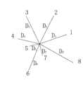
进一步的,通过下述方法确定平面网格节点的Z坐标:采用反距离插值方法,将平面投影范围划分n个象限,在等高线或地质界面高程点数据中,寻找每个象限内在投影平面上离被插值点(X,Y,Z)最近的高程点(Xi,Yi,Zi),计算被插值点的Z坐标Further, the Z coordinate of the plane grid node is determined by the following method: by using the inverse distance interpolation method, the plane projection range is divided into n quadrants, and in the contour line or geological interface elevation point data, find the inner projection plane in each quadrant. On the elevation point (Xi , Yi , Zi ) closest to the interpolated point (X, Y, Z), calculate the Z coordinate of the interpolated point

式中,Di为第i象限在平面投影上距被插值点最近的高程点与该被插值点间的距离,
其中,对平面投影进行范围划分时,一般将其范围划分为8个象限。Among them, when the plane projection is divided into a range, the range is generally divided into 8 quadrants.
上述步骤4)中,根据步骤3)获得的三维网格节点数据,过滤掉重复节点,并对节点重新编号;然后对空间节点进行有序组合,构建边坡三维有限元网格的单元,单元内节点组合次序采用右手法则。In the above-mentioned step 4), according to the three-dimensional grid node data obtained in the step 3), the repeated nodes are filtered out, and the nodes are renumbered; then the spatial nodes are combined in an orderly manner, and the element of the three-dimensional finite element mesh of the slope is constructed, and the element The inner node combination order adopts the right-hand rule.
上述步骤4)中生成的有限元网格均为六面体单元,在地质界面附近的过渡区域可能会出现一些退化的六面体单元,步骤5)中,检查有限元网格质量时,如果有限元网格的单元在等参变换时雅克比行列式的值均大于0,表明有限元网格质量达到要求。The finite element meshes generated in the above step 4) are all hexahedral elements, and some degenerate hexahedral elements may appear in the transition area near the geological interface. In step 5), when checking the quality of the finite element mesh, if the finite element mesh The values of the Jacobian determinant of the elements in the isoparametric transformation are all greater than 0, indicating that the quality of the finite element mesh meets the requirements.
有益效果:与现有技术相比,本发明的显著优点在于,本发明的三维有限元网格生成方法提供了一种切实可行的有限元网格划分思路,能够高效率、高精度地建立复杂地质条件下的边坡三维有限元计算网格,可以有效控制有限元网格的质量和数量,可重复性强、不需要简化处理、有限元计算效果较好;该方法能很好地应用于水利工程及岩土工程领域的边坡有限元网格划分,可以有效运用于有限元分析与计算,特别是复杂地质条件下的边坡稳定分析,仿真计算效果较好。Beneficial effects: Compared with the prior art, the significant advantage of the present invention is that the three-dimensional finite element mesh generation method of the present invention provides a feasible finite element mesh division idea, which can efficiently and accurately establish complex The three-dimensional finite element calculation mesh of the slope under geological conditions can effectively control the quality and quantity of the finite element mesh, with strong repeatability, no need for simplified processing, and good finite element calculation effect; this method can be well applied to The finite element meshing of slopes in the field of hydraulic engineering and geotechnical engineering can be effectively used in finite element analysis and calculation, especially for slope stability analysis under complex geological conditions, and the simulation calculation effect is good.
附图说明Description of drawings
图1为本发明的一种复杂地质条件下边坡三维有限元网格生成方法的流程图;1 is a flowchart of a method for generating a three-dimensional finite element grid of a slope under complex geological conditions according to the present invention;
图2为实施例中某研究区域的地形图和目标范围平面投影图;Fig. 2 is the topographic map of a certain research area in the embodiment and the plane projection map of the target area;
图3为实施例中采用反距离插值方法构建节点的示意图;Fig. 3 is the schematic diagram that adopts the inverse distance interpolation method to construct the node in the embodiment;
图4为实施例中有限元网格的单元节点编号顺序示意图;Fig. 4 is the schematic diagram of the element node numbering sequence of the finite element mesh in the embodiment;
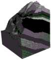
图5为实施例中生成的某研究区域的三维有限元网格图。FIG. 5 is a three-dimensional finite element mesh diagram of a certain research area generated in the embodiment.
具体实施方式Detailed ways
下面结合附图对本发明的技术方案作进一步说明。The technical solutions of the present invention will be further described below with reference to the accompanying drawings.
如图1,本发明的一种复杂地质条件下边坡三维有限元网格生成方法包括下述步骤:As shown in Figure 1, a method for generating a three-dimensional finite element grid of a slope under complex geological conditions of the present invention includes the following steps:
1)基于CAD平台提取地形等高线和地质界面高程点数据;1) Extract terrain contour and geological interface elevation point data based on CAD platform;
边坡等高线和地质界面信息通常由地勘人员用CAD软件绘制,利用CAD软件可使等高线和地质界面具备X、Y、Z三向坐标信息;具体而言,采用不同图层定义等高线和不同地质界面,编辑等高线和不同地质界面图元,并将所有图元定义为POLYLINE(多段线),将CAD文件另存为dxf格式,采用Fortran语言编写程序,读取POLYLINE节点坐标数据,读入的多段线节点坐标即为等高线和地质界面的高程点坐标数据,将其分别保存在不同的txt文件中,从而提取到等高线和各地质界面上高程点的空间X、Y、Z三向坐标信息;若边坡等高线或地质界面上高程点数量不足,可在图元内采用等分的方式添加高程控制点数据,从而可提高后续步骤中的反距离插值精度。Slope contours and geological interface information are usually drawn by geological prospectors using CAD software. Using CAD software, contours and geological interfaces can have X, Y, and Z coordinate information; specifically, different layer definitions are used. Contour lines and different geological interfaces, edit contour lines and different geological interface primitives, define all primitives as POLYLINE (polylines), save CAD files as dxf format, use Fortran language to write programs, read POLYLINE nodes Coordinate data, the read-in polyline node coordinates are the elevation point coordinate data of the contour line and the geological interface, which are saved in different txt files respectively, so as to extract the space of the contour line and the elevation points on each geological interface X, Y, Z three-way coordinate information; if the number of elevation points on the slope contour or geological interface is insufficient, the elevation control point data can be added in the graphic element by equal division, thereby improving the inverse distance in the subsequent steps. Interpolation precision.
2)建立目标范围平面投影的网格节点数据;2) Establish grid node data of the plane projection of the target range;
先确定有限元计算范围,给定有限元网格平面投影范围,然后采用平面内两个方向等分方式,生成目标范围网格节点的X、Y坐标数据,记录节点的行数和列数。First determine the finite element calculation range, give the projection range of the finite element grid plane, and then use two equal divisions in the plane to generate the X and Y coordinate data of the grid nodes in the target range, and record the number of rows and columns of nodes.
3)根据步骤2)获得的平面网格节点数据以及步骤1)获得的等高线高程点数据和地质界面控制点数据,基于反距离插值方法构建目标范围内的三维网格节点数据;3) according to the plane grid node data obtained in step 2) and the contour elevation point data and geological interface control point data obtained in step 1), construct the three-dimensional grid node data within the target range based on the inverse distance interpolation method;
首先确定目标范围的最低高程,采用反距离插值方法,根据步骤2)获得的目标范围内平面网格节点的X、Y坐标数据以及步骤1)获得的等高线和地质界面高程点数据,插值得到平面网格节点的Z坐标信息,生成网格划分的三维控制面的点云数据;然后以等高线或地质界面为源面,下一层地质界面为目标面,采用扫略的方式向下平移直至最低高程,获得目标范围内的三维网格节点数据,并记录节点的层数。First determine the minimum elevation of the target range, use the inverse distance interpolation method, and interpolate based on the X and Y coordinate data of the plane grid nodes in the target range obtained in step 2) and the contour and geological interface elevation point data obtained in step 1). The Z coordinate information of the plane grid nodes is obtained, and the point cloud data of the three-dimensional control surface divided by the grid is generated; Pan down until the lowest elevation, obtain the 3D grid node data within the target range, and record the number of layers of nodes.
平面网格节点的Z坐标信息的获取方法具体为:The method for obtaining the Z coordinate information of the plane grid node is as follows:
采用反距离插值方法,将平面投影范围划分n个象限,在等高线或地质界面高程点数据中,寻找每个象限内在投影平面上离被插值点(X,Y,Z)最近的高程点(Xi,Yi,Zi),计算被插值点的Z坐标Using the inverse distance interpolation method, the plane projection range is divided into n quadrants, and in the contour line or geological interface elevation point data, find the elevation point closest to the interpolated point (X, Y, Z) on the projection plane in each quadrant (Xi ,Yi , Z i) , calculate the Z coordinate of the interpolated point

式中,Di为第i象限在平面投影上距被插值点最近的高程点与该被插值点间的距离,
4)创建规定节点次序的网格节点及单元,得到三维有限元网格;4) Create grid nodes and elements that specify the node order to obtain a three-dimensional finite element grid;
根据步骤3)获得的三维网格节点数据,过滤掉重复节点,然后对节点重新编号;再对空间节点进行有序组合,构建边坡三维有限元网格的单元,单元内节点组合次序采用右手法则。According to the three-dimensional grid node data obtained in step 3), the repeated nodes are filtered out, and then the nodes are renumbered; and then the spatial nodes are combined in an orderly manner to construct a three-dimensional finite element grid element of the slope. law.
5)检查生成的有限元网格质量:步骤4)中生成的有限元网格均为六面体单元,在地质界面附近的过渡区域可能会出现一些退化的六面体单元,检查有限元网格质量时,如果有限元网格的单元在等参变换时雅克比行列式的值均大于0,表明有限元网格质量达到要求;如网格质量不合格,返回步骤3),重新生成有限元网格。5) Check the quality of the generated finite element mesh: The finite element meshes generated in step 4) are all hexahedral elements, and some degenerate hexahedral elements may appear in the transition area near the geological interface. When checking the quality of the finite element mesh, If the value of the Jacobian determinant of the elements of the finite element mesh is greater than 0 during isoparametric transformation, it indicates that the quality of the finite element mesh meets the requirements; if the quality of the mesh is unqualified, go back to step 3) and regenerate the finite element mesh.
该方法能够高效率、高精度地建立复杂地质条件下的边坡三维有限元计算网格,可以有效控制有限元网格的质量和数量,可重复性强、不需要简化处理、有限元计算效果较好。This method can efficiently and accurately establish a three-dimensional finite element calculation grid for slopes under complex geological conditions, and can effectively control the quality and quantity of finite element grids. better.
实施例Example
一种复杂地质条件下边坡三维有限元网格生成方法,包括以下步骤:A method for generating a three-dimensional finite element grid of a slope under complex geological conditions, comprising the following steps:
1)基于CAD平台提取地形等高线和地质界面高程点数据1) Extract terrain contour and geological interface elevation point data based on CAD platform
根据地勘人员提供的边坡地形地貌图及地质图,提取边坡等高线和地质界面的图形元素POLYLINE(多段线),利用CAD编辑使等高线和地质界面图元具备X、Y、Z三向坐标信息,并另存为dxf文件。采用Fortran语言编写程序,读取POLYLINE节点坐标数据,并将等高线数据和不同地质界面数据分别保存在不同的txt文件中,在多段线相邻节点之间添加数据点,增加控制高程点的个数,提高反距离插值精度。通过该方法提取了等高线和不同地质界面共13个txt文件,其中包括开挖线等控制信息。According to the topographic map and geological map of the slope provided by the geological prospector, extract the graphic element POLYLINE (polyline) of the slope contour line and geological interface, and use CAD editing to make the contour line and geological interface primitives have X, Y, Z Three-way coordinate information, and save as a dxf file. Write a program in Fortran language, read the coordinate data of POLYLINE nodes, save the contour data and different geological interface data in different txt files, add data points between adjacent nodes of the polyline, and increase the control elevation points. to improve the precision of inverse distance interpolation. A total of 13 txt files of contour lines and different geological interfaces were extracted by this method, including control information such as excavation lines.
2)建立目标范围平面投影的网格节点数据2) Establish the grid node data of the plane projection of the target range
确定有限元计算范围(X向:100m~470m;Y向:-120m~400m;Z向:800m~地表),在平面投影上,采用两个方向等分方式,生成80×80共6400个网格节点,并记录节点的行数、列数以及X、Y坐标数据。获得的目标范围平面投影图如图2。Determine the finite element calculation range (X direction: 100m~470m; Y direction: -120m~400m; Z direction: 800m~surface), on the plane projection, adopt the method of equal division in two directions to generate a total of 6400 meshes of 80×80 Grid node, and record the number of rows, columns, and X, Y coordinate data of the node. The obtained plane projection map of the target range is shown in Figure 2.
3)基于反距离插值方法构建目标范围内的三维网格节点数据3) Construct 3D grid node data within the target range based on the inverse distance interpolation method
如图3,将平面分为8个象限,根据平面网格X和Y坐标信息,在等高线高程点数据中,寻找每个象限内在平面投影上离平面网格节点最近的高程点,记录它们与网格节点的平面投影距离Di(i=1,2,…,8),采用公式(1)计算平面网格节点的Z坐标,生成等高线三维控制面的点云数据,采用同样的方法可以得到各地质界面及最低高程的点云数据。As shown in Figure 3, the plane is divided into 8 quadrants. According to the X and Y coordinate information of the plane grid, in the contour elevation point data, find the elevation point closest to the plane grid node on the plane projection in each quadrant, and record The plane projection distance Di (i=1,2,...,8) between them and the grid nodes, the Z coordinate of the plane grid nodes is calculated by formula (1), and the point cloud data of the three-dimensional control surface of the contour line is generated. The same method can obtain the point cloud data of each geological interface and the lowest elevation.
以等高线或地质界面为源面,下一层地质界面为目标面,采用扫略的方式向下逐层平移直至最低高程800m,获得目标范围内的三维网格节点数据,记录节点的编号层数。通过本方法可以获取三维网格节点三向坐标信息以及所属行数、列数和层数。Taking the contour line or geological interface as the source surface and the next layer of geological interface as the target surface, use the sweeping method to translate down layer by layer until the lowest elevation is 800m, obtain the 3D grid node data within the target range, and record the number of the node layers. Through this method, the three-dimensional coordinate information of the three-dimensional grid node and the number of rows, columns and layers to which it belongs can be obtained.
4)创建规定节点次序的三维节点及单元4) Create 3D nodes and elements that specify the order of nodes
根据网格节点坐标数据,过滤重复节点,可以获取131670个节点并重新编号;基于右手法则,对空间节点进行有序组合,构建边坡三维有限元网格的单元,单元内节点组合次序如图4。通过本方法获得边坡三维有限元网格,如图5,包括131647个单元和131670个节点。According to the grid node coordinate data, 131,670 nodes can be obtained and renumbered by filtering the repeated nodes; based on the right-hand rule, the spatial nodes are combined in an orderly manner to construct a three-dimensional finite element mesh element of the slope. The order of the node combination in the element is shown in the figure 4. The three-dimensional finite element mesh of the slope is obtained by this method, as shown in Figure 5, including 131,647 elements and 131,670 nodes.
5)检查有限元网格质量5) Check the quality of the finite element mesh
本工程实例有限元网格包含131647个单元和131670个节点,大多数是六面体网格,只有在地质界面附近的过渡区域可能会出现一些退化的六面体单元,单元在等参变换时雅克比行列式的值均大于0,表明网格质量达到要求;通过合理选择网格的规模和单元的大小,做到兼顾有限元计算精度和效率,从而达到提高工作效率和确保计算数据正确可靠的目的。The finite element mesh of this project example contains 131,647 elements and 131,670 nodes, most of which are hexahedral meshes. Only in the transition area near the geological interface, some degenerate hexahedral elements may appear. The elements have the Jacobian determinant during isoparametric transformation. The values of all are greater than 0, indicating that the grid quality meets the requirements; by reasonably selecting the scale of the grid and the size of the element, the accuracy and efficiency of the finite element calculation can be taken into account, so as to improve the work efficiency and ensure the correctness and reliability of the calculation data.
Claims (5)


Priority Applications (1)
| Application Number | Priority Date | Filing Date | Title |
|---|---|---|---|
| CN201711189215.2ACN107886573B (en) | 2017-11-24 | 2017-11-24 | A three-dimensional finite element mesh generation method for slopes under complex geological conditions |
Applications Claiming Priority (1)
| Application Number | Priority Date | Filing Date | Title |
|---|---|---|---|
| CN201711189215.2ACN107886573B (en) | 2017-11-24 | 2017-11-24 | A three-dimensional finite element mesh generation method for slopes under complex geological conditions |
Publications (2)
| Publication Number | Publication Date |
|---|---|
| CN107886573A CN107886573A (en) | 2018-04-06 |
| CN107886573Btrue CN107886573B (en) | 2020-07-14 |
Family
ID=61775121
Family Applications (1)
| Application Number | Title | Priority Date | Filing Date |
|---|---|---|---|
| CN201711189215.2AActiveCN107886573B (en) | 2017-11-24 | 2017-11-24 | A three-dimensional finite element mesh generation method for slopes under complex geological conditions |
Country Status (1)
| Country | Link |
|---|---|
| CN (1) | CN107886573B (en) |
Families Citing this family (5)
| Publication number | Priority date | Publication date | Assignee | Title |
|---|---|---|---|---|
| CN110264405B (en)* | 2019-06-17 | 2023-05-09 | 深圳飞马机器人科技有限公司 | Image processing method, device, server and storage medium based on interpolation algorithm |
| CN112528541A (en)* | 2020-12-09 | 2021-03-19 | 中国航空工业集团公司沈阳飞机设计研究所 | Node reconstruction-based double-curvature canopy finite element modeling method |
| CN114373032B (en)* | 2022-01-11 | 2025-02-11 | 土巴兔集团股份有限公司 | Three-dimensional mesh deformation method based on contour skeleton and related device |
| CN115830250A (en)* | 2022-10-09 | 2023-03-21 | 中铁第四勘察设计院集团有限公司 | Slope model generation method, device, equipment and storage medium |
| CN115619978B (en)* | 2022-11-21 | 2023-06-02 | 广州中望龙腾软件股份有限公司 | Grid surface construction method, terminal and storage medium |
Citations (3)
| Publication number | Priority date | Publication date | Assignee | Title |
|---|---|---|---|---|
| CN103279985A (en)* | 2013-06-13 | 2013-09-04 | 河海大学 | Intelligentized modeling method for three-dimensional finite element model of complex terrain structural system |
| CN103336854A (en)* | 2013-05-13 | 2013-10-02 | 河海大学 | Modeling method of three-dimensional finite element model of high slope |
| CN107240152A (en)* | 2016-03-28 | 2017-10-10 | 中国石油化工股份有限公司 | The modeling method and system of three-dimensional geological model |
- 2017
- 2017-11-24CNCN201711189215.2Apatent/CN107886573B/enactiveActive
Patent Citations (3)
| Publication number | Priority date | Publication date | Assignee | Title |
|---|---|---|---|---|
| CN103336854A (en)* | 2013-05-13 | 2013-10-02 | 河海大学 | Modeling method of three-dimensional finite element model of high slope |
| CN103279985A (en)* | 2013-06-13 | 2013-09-04 | 河海大学 | Intelligentized modeling method for three-dimensional finite element model of complex terrain structural system |
| CN107240152A (en)* | 2016-03-28 | 2017-10-10 | 中国石油化工股份有限公司 | The modeling method and system of three-dimensional geological model |
Non-Patent Citations (4)
| Title |
|---|
| 《利用AutoCAD VBA获取等高线上高程点的方法》;李建;《实验室研究与探索》;20091031;第28卷(第10期);第172-175页* |
| 《用于边界面法的三维体网格生成方法》;黄橙;《万方数据》;20140819;第3-4,17,40-55页* |
| 《考虑三维地形的水工建筑物有限元网格剖分》;王煜等;《水电与新能源》;20100712(第3期);第4-5页* |
| 王煜等.《考虑三维地形的水工建筑物有限元网格剖分》.《水电与新能源》.2010,(第3期),* |
Also Published As
| Publication number | Publication date |
|---|---|
| CN107886573A (en) | 2018-04-06 |
Similar Documents
| Publication | Publication Date | Title |
|---|---|---|
| CN107886573B (en) | A three-dimensional finite element mesh generation method for slopes under complex geological conditions | |
| CN107562833B (en) | Contour-based 3D Discrete Element Numerical Modeling Method for Complex Terrain | |
| CN105184867B (en) | The three dimensional contour line method of rule-based grid and Corner-point Grids technology | |
| CN111950051B (en) | BIM-based 3D geological modeling and construction application method based on geological body model | |
| WO2022007398A1 (en) | Unstructured grid flood simulation system based on gpu acceleration thechnology | |
| CN104635262B (en) | A kind of positive reversed fault isopleth automatic generation method based on extended rectangular grid | |
| CN109859317B (en) | 3DGIS terrain model rapid modeling method based on CASS and CATIA | |
| CN103336854B (en) | A kind of modeling method of high slope three-dimensional finite element model | |
| CN102194253A (en) | Method for generating tetrahedron gridding for three-dimensional geological structure | |
| CN108978573A (en) | A kind of method of terrain data quick visualization auxiliary river bed change research | |
| CN112734929B (en) | Method for calculating excavation volume of complex earth and rockfill dam earth stock ground based on grid subdivision algorithm | |
| CN115469361B (en) | Clastic rock stratum three-dimensional geological modeling method | |
| CN105118091A (en) | Method and system for constructing multi-precision non-uniform geological grid curved surface model | |
| CN111784831A (en) | A three-dimensional inundation analysis method of urban river flood based on oblique photography | |
| CN114549774A (en) | A 3D stratigraphic modeling method based on borehole data | |
| CN103256914B (en) | A kind of method and system calculating silt arrester inundated area based on DEM | |
| CN110968930B (en) | Geological variable attribute interpolation method and system | |
| CN106023311B (en) | Improve the method that dimensional topography generates precision | |
| CN118332902A (en) | Three-dimensional numerical simulation method for seepage field evolution in fractured rock tunnels | |
| CN111951394B (en) | Method and device for constructing three-dimensional model of fault structural unit based on geological map | |
| CN120374665A (en) | Automatic segmentation method and system based on deep foundation pit point cloud model | |
| CN115908733A (en) | Real-time segmentation and three-dimensional visualization method for angular point grid geological model | |
| CN105045958A (en) | Implementation system and method of GPS (Global Positioning System) elevation fitting on the basis of BP (Back Propagation) neural network | |
| CN112967354B (en) | A method for generating two-dimensional terrain based on finite fixed-section terrain and remote sensing image data | |
| CN118298123A (en) | Large-scale data coupling three-dimensional geological fine modeling method and system |
Legal Events
| Date | Code | Title | Description |
|---|---|---|---|
| PB01 | Publication | ||
| PB01 | Publication | ||
| SE01 | Entry into force of request for substantive examination | ||
| SE01 | Entry into force of request for substantive examination | ||
| GR01 | Patent grant | ||
| GR01 | Patent grant |