CN107850380B - Vacuum insulators and refrigerators - Google Patents
Vacuum insulators and refrigeratorsDownload PDFInfo
- Publication number
- CN107850380B CN107850380BCN201680045949.0ACN201680045949ACN107850380BCN 107850380 BCN107850380 BCN 107850380BCN 201680045949 ACN201680045949 ACN 201680045949ACN 107850380 BCN107850380 BCN 107850380B
- Authority
- CN
- China
- Prior art keywords
- space
- vacuum
- plate member
- plate
- heat
- Prior art date
- Legal status (The legal status is an assumption and is not a legal conclusion. Google has not performed a legal analysis and makes no representation as to the accuracy of the status listed.)
- Active
Links
Images


Classifications
- F—MECHANICAL ENGINEERING; LIGHTING; HEATING; WEAPONS; BLASTING
- F25—REFRIGERATION OR COOLING; COMBINED HEATING AND REFRIGERATION SYSTEMS; HEAT PUMP SYSTEMS; MANUFACTURE OR STORAGE OF ICE; LIQUEFACTION SOLIDIFICATION OF GASES
- F25D—REFRIGERATORS; COLD ROOMS; ICE-BOXES; COOLING OR FREEZING APPARATUS NOT OTHERWISE PROVIDED FOR
- F25D23/00—General constructional features
- F25D23/06—Walls
- F25D23/065—Details
- F—MECHANICAL ENGINEERING; LIGHTING; HEATING; WEAPONS; BLASTING
- F25—REFRIGERATION OR COOLING; COMBINED HEATING AND REFRIGERATION SYSTEMS; HEAT PUMP SYSTEMS; MANUFACTURE OR STORAGE OF ICE; LIQUEFACTION SOLIDIFICATION OF GASES
- F25D—REFRIGERATORS; COLD ROOMS; ICE-BOXES; COOLING OR FREEZING APPARATUS NOT OTHERWISE PROVIDED FOR
- F25D23/00—General constructional features
- F25D23/06—Walls
- F25D23/062—Walls defining a cabinet
- F25D23/064—Walls defining a cabinet formed by moulding, e.g. moulding in situ
- F—MECHANICAL ENGINEERING; LIGHTING; HEATING; WEAPONS; BLASTING
- F16—ENGINEERING ELEMENTS AND UNITS; GENERAL MEASURES FOR PRODUCING AND MAINTAINING EFFECTIVE FUNCTIONING OF MACHINES OR INSTALLATIONS; THERMAL INSULATION IN GENERAL
- F16L—PIPES; JOINTS OR FITTINGS FOR PIPES; SUPPORTS FOR PIPES, CABLES OR PROTECTIVE TUBING; MEANS FOR THERMAL INSULATION IN GENERAL
- F16L59/00—Thermal insulation in general
- F16L59/06—Arrangements using an air layer or vacuum
- F16L59/065—Arrangements using an air layer or vacuum using vacuum
- F—MECHANICAL ENGINEERING; LIGHTING; HEATING; WEAPONS; BLASTING
- F25—REFRIGERATION OR COOLING; COMBINED HEATING AND REFRIGERATION SYSTEMS; HEAT PUMP SYSTEMS; MANUFACTURE OR STORAGE OF ICE; LIQUEFACTION SOLIDIFICATION OF GASES
- F25D—REFRIGERATORS; COLD ROOMS; ICE-BOXES; COOLING OR FREEZING APPARATUS NOT OTHERWISE PROVIDED FOR
- F25D19/00—Arrangement or mounting of refrigeration units with respect to devices or objects to be refrigerated, e.g. infrared detectors
- F25D19/006—Thermal coupling structure or interface
- F—MECHANICAL ENGINEERING; LIGHTING; HEATING; WEAPONS; BLASTING
- F25—REFRIGERATION OR COOLING; COMBINED HEATING AND REFRIGERATION SYSTEMS; HEAT PUMP SYSTEMS; MANUFACTURE OR STORAGE OF ICE; LIQUEFACTION SOLIDIFICATION OF GASES
- F25D—REFRIGERATORS; COLD ROOMS; ICE-BOXES; COOLING OR FREEZING APPARATUS NOT OTHERWISE PROVIDED FOR
- F25D23/00—General constructional features
- F25D23/02—Doors; Covers
- F25D23/028—Details
- F—MECHANICAL ENGINEERING; LIGHTING; HEATING; WEAPONS; BLASTING
- F25—REFRIGERATION OR COOLING; COMBINED HEATING AND REFRIGERATION SYSTEMS; HEAT PUMP SYSTEMS; MANUFACTURE OR STORAGE OF ICE; LIQUEFACTION SOLIDIFICATION OF GASES
- F25D—REFRIGERATORS; COLD ROOMS; ICE-BOXES; COOLING OR FREEZING APPARATUS NOT OTHERWISE PROVIDED FOR
- F25D23/00—General constructional features
- F25D23/06—Walls
- F25D23/062—Walls defining a cabinet
- F25D23/063—Walls defining a cabinet formed by an assembly of panels
- F—MECHANICAL ENGINEERING; LIGHTING; HEATING; WEAPONS; BLASTING
- F25—REFRIGERATION OR COOLING; COMBINED HEATING AND REFRIGERATION SYSTEMS; HEAT PUMP SYSTEMS; MANUFACTURE OR STORAGE OF ICE; LIQUEFACTION SOLIDIFICATION OF GASES
- F25D—REFRIGERATORS; COLD ROOMS; ICE-BOXES; COOLING OR FREEZING APPARATUS NOT OTHERWISE PROVIDED FOR
- F25D23/00—General constructional features
- F25D23/08—Parts formed wholly or mainly of plastics materials
- F25D23/082—Strips
- F—MECHANICAL ENGINEERING; LIGHTING; HEATING; WEAPONS; BLASTING
- F25—REFRIGERATION OR COOLING; COMBINED HEATING AND REFRIGERATION SYSTEMS; HEAT PUMP SYSTEMS; MANUFACTURE OR STORAGE OF ICE; LIQUEFACTION SOLIDIFICATION OF GASES
- F25D—REFRIGERATORS; COLD ROOMS; ICE-BOXES; COOLING OR FREEZING APPARATUS NOT OTHERWISE PROVIDED FOR
- F25D2201/00—Insulation
- F25D2201/10—Insulation with respect to heat
- F25D2201/14—Insulation with respect to heat using subatmospheric pressure
- F—MECHANICAL ENGINEERING; LIGHTING; HEATING; WEAPONS; BLASTING
- F25—REFRIGERATION OR COOLING; COMBINED HEATING AND REFRIGERATION SYSTEMS; HEAT PUMP SYSTEMS; MANUFACTURE OR STORAGE OF ICE; LIQUEFACTION SOLIDIFICATION OF GASES
- F25D—REFRIGERATORS; COLD ROOMS; ICE-BOXES; COOLING OR FREEZING APPARATUS NOT OTHERWISE PROVIDED FOR
- F25D2323/00—General constructional features not provided for in other groups of this subclass
- F—MECHANICAL ENGINEERING; LIGHTING; HEATING; WEAPONS; BLASTING
- F25—REFRIGERATION OR COOLING; COMBINED HEATING AND REFRIGERATION SYSTEMS; HEAT PUMP SYSTEMS; MANUFACTURE OR STORAGE OF ICE; LIQUEFACTION SOLIDIFICATION OF GASES
- F25D—REFRIGERATORS; COLD ROOMS; ICE-BOXES; COOLING OR FREEZING APPARATUS NOT OTHERWISE PROVIDED FOR
- F25D2500/00—Problems to be solved
- F25D2500/02—Geometry problems
- Y—GENERAL TAGGING OF NEW TECHNOLOGICAL DEVELOPMENTS; GENERAL TAGGING OF CROSS-SECTIONAL TECHNOLOGIES SPANNING OVER SEVERAL SECTIONS OF THE IPC; TECHNICAL SUBJECTS COVERED BY FORMER USPC CROSS-REFERENCE ART COLLECTIONS [XRACs] AND DIGESTS
- Y02—TECHNOLOGIES OR APPLICATIONS FOR MITIGATION OR ADAPTATION AGAINST CLIMATE CHANGE
- Y02A—TECHNOLOGIES FOR ADAPTATION TO CLIMATE CHANGE
- Y02A30/00—Adapting or protecting infrastructure or their operation
- Y02A30/24—Structural elements or technologies for improving thermal insulation
- Y02A30/242—Slab shaped vacuum insulation
- Y—GENERAL TAGGING OF NEW TECHNOLOGICAL DEVELOPMENTS; GENERAL TAGGING OF CROSS-SECTIONAL TECHNOLOGIES SPANNING OVER SEVERAL SECTIONS OF THE IPC; TECHNICAL SUBJECTS COVERED BY FORMER USPC CROSS-REFERENCE ART COLLECTIONS [XRACs] AND DIGESTS
- Y02—TECHNOLOGIES OR APPLICATIONS FOR MITIGATION OR ADAPTATION AGAINST CLIMATE CHANGE
- Y02B—CLIMATE CHANGE MITIGATION TECHNOLOGIES RELATED TO BUILDINGS, e.g. HOUSING, HOUSE APPLIANCES OR RELATED END-USER APPLICATIONS
- Y02B40/00—Technologies aiming at improving the efficiency of home appliances, e.g. induction cooking or efficient technologies for refrigerators, freezers or dish washers
- Y—GENERAL TAGGING OF NEW TECHNOLOGICAL DEVELOPMENTS; GENERAL TAGGING OF CROSS-SECTIONAL TECHNOLOGIES SPANNING OVER SEVERAL SECTIONS OF THE IPC; TECHNICAL SUBJECTS COVERED BY FORMER USPC CROSS-REFERENCE ART COLLECTIONS [XRACs] AND DIGESTS
- Y02—TECHNOLOGIES OR APPLICATIONS FOR MITIGATION OR ADAPTATION AGAINST CLIMATE CHANGE
- Y02B—CLIMATE CHANGE MITIGATION TECHNOLOGIES RELATED TO BUILDINGS, e.g. HOUSING, HOUSE APPLIANCES OR RELATED END-USER APPLICATIONS
- Y02B80/00—Architectural or constructional elements improving the thermal performance of buildings
- Y02B80/10—Insulation, e.g. vacuum or aerogel insulation
Landscapes
- Engineering & Computer Science (AREA)
- General Engineering & Computer Science (AREA)
- Mechanical Engineering (AREA)
- Chemical & Material Sciences (AREA)
- Combustion & Propulsion (AREA)
- Physics & Mathematics (AREA)
- Thermal Sciences (AREA)
- Refrigerator Housings (AREA)
Abstract
Description
Translated fromChinese技术领域technical field
本公开涉及一种真空绝热体和一种冰箱。The present disclosure relates to a vacuum insulator and a refrigerator.
背景技术Background technique
真空绝热体是用于通过对其体内抽真空来抑制热传递(传热,heat transfer)的产品。真空绝热体可以减少通过对流和传导进行的热传递,因此被应用于加热装置和制冷装置。在应用于冰箱的常规绝热方法中,通常设置具有约30cm或更大厚度的泡沫聚氨酯绝热壁(尽管其以不同方式应用于冷藏和冷冻中)。但是,冰箱的内部容积因而减小。A vacuum insulator is a product for suppressing heat transfer (heat transfer) by evacuating its body. Vacuum insulators can reduce heat transfer by convection and conduction and are therefore used in heating and cooling devices. In conventional insulation methods applied to refrigerators, foamed polyurethane insulation walls having a thickness of about 30 cm or more are usually provided (although they are applied in refrigeration and freezing in different ways). However, the internal volume of the refrigerator is thus reduced.
为了增大冰箱的内部容积,尝试将真空绝热体应用于冰箱。In order to increase the internal volume of the refrigerator, an attempt has been made to apply a vacuum insulator to the refrigerator.
首先,本申请人的韩国专利第10-0343719号(参考文献1)已经公开。根据参考文献1,公开了一种方法,其中制备真空绝热板,然后将其装入冰箱的壁内,真空绝热板的外部用如泡沫聚苯乙烯(聚苯乙烯)的单独模制件完成(整饰)。根据该方法,不需要额外发泡,并且提高了冰箱的绝热性能。但是,制造成本增加,并且制造方法复杂。作为另一个示例,韩国专利公开第10-2015-0012712号(参考文献2)中公开了一种使用真空绝热材料设置壁并使用泡沫填充材料附加地设置绝热壁的技术(technique,方法)。根据参考文献2,制造成本增加,并且制造方法复杂。First, the applicant's Korean Patent No. 10-0343719 (Reference 1) has been disclosed. According to
作为另一个示例,尝试使用单个产品的真空绝热体来制造冰箱的所有壁。例如,美国专利公开公报第US2040226956A1号(参考文献3)中公开了一种提供处于真空状态的冰箱的绝热结构的技术。As another example, try making all the walls of a refrigerator using a single product vacuum insulation. For example, US Patent Publication No. US2040226956A1 (Reference 3) discloses a technique of providing a heat insulating structure of a refrigerator in a vacuum state.
发明内容SUMMARY OF THE INVENTION
技术问题technical problem
然而,通过提供处于充分真空状态的冰箱的壁难以获得实用化水平的绝热效果。特别地,难以防止在具有不同温度的外壳体和内壳体之间的接触部处发生热传递。此外,难以保持稳定的真空状态。而且,难以防止真空状态下声压导致的壳体变形。由于这些问题,参考文献3的技术被局限于低温制冷装置,而不适用于一般家庭使用的制冷装置。However, it is difficult to obtain a practical level of thermal insulation effect by providing the wall of the refrigerator in a sufficient vacuum state. In particular, it is difficult to prevent heat transfer from occurring at the contact portion between the outer casing and the inner casing having different temperatures. Furthermore, it is difficult to maintain a stable vacuum state. Also, it is difficult to prevent deformation of the housing due to sound pressure in a vacuum state. Due to these problems, the technique of
技术方案Technical solutions
实施例提供一种真空绝热体和一种冰箱,其能够在真空状态下获得足够的绝热效果并在商业上应用。The embodiment provides a vacuum insulator and a refrigerator, which can obtain a sufficient thermal insulation effect in a vacuum state and are commercially applicable.
在一个实施例中,真空绝热体包括:第一板构件,限定用于第一空间的壁的至少一部分;第二板构件,限定用于第二空间的壁的至少一部分,第二空间具有与第一空间不同的温度;密封部,密封第一板构件和第二板构件,以提供具有在第一空间的温度与第二空间的温度之间的温度且处于真空状态的第三空间;支撑单元,保持第三空间;抗热单元,用于减少第一板构件与第二板构件之间的传热量;以及排气端口,通过排气端口排出第三空间中的气体,其中,第二板构件包括前部和侧部,侧部具有与前部不同的延伸方向,以及侧部限定用于第三空间的壁的至少一部分。In one embodiment, the vacuum insulator includes: a first plate member defining at least a portion of a wall for the first space; a second plate member defining at least a portion of the wall for the second space, the second space having a different temperature of the first space; a sealing portion that seals the first plate member and the second plate member to provide a third space having a temperature between the temperature of the first space and the temperature of the second space and in a vacuum state; a support a unit for maintaining the third space; a heat-resistant unit for reducing heat transfer between the first plate member and the second plate member; and an exhaust port for exhausting the gas in the third space through the exhaust port, wherein the second The plate member includes a front portion and a side portion, the side portion has a different extending direction from the front portion, and the side portion defines at least a portion of a wall for the third space.
侧部可相对于前部弯曲。前部可暴露于外部。真空绝热体可包括被设置在第一板构件的边缘部处的侧框架,侧框架被固定到侧部。侧框架和侧部可紧固到彼此的部分被焊接。侧框架和第二板构件可在其端部彼此紧固,以提供边缘部。侧部可以是第二板构件的边缘部。真空绝热体可包括抗传导片,抗传导片的两个端部分别紧固到第一板构件和侧框架,以阻止沿着用于第三空间的壁流动的热传导。The sides may be curved relative to the front. The front part may be exposed to the outside. The vacuum insulator may include a side frame provided at an edge portion of the first plate member, and the side frame is fixed to the side portion. The parts of the side frame and the side parts which can be fastened to each other are welded. The side frame and the second plate member may be fastened to each other at their ends to provide an edge portion. The side portion may be an edge portion of the second plate member. The vacuum insulator may include anti-conduction sheets, both ends of which are fastened to the first plate member and the side frame, respectively, to prevent heat conduction flowing along the wall for the third space.
在另一实施例中,真空绝热体包括:第一板构件,限定用于第一空间的壁的至少一部分;第二板构件,限定用于第二空间的壁的至少一部分,第二空间具有与第一空间不同的温度;密封部,密封第一板构件和第二板构件,以提供具有在第一空间的温度与第二空间的温度之间的温度且处于真空状态的第三空间;支撑单元,保持第三空间;抗热单元,用于减少第一板构件与第二板构件之间的传热量;排气端口,通过排气端口排出第三空间中的气体;其中,抗热单元包括抗传导片,抗传导片能够阻止沿着用于第三空间的壁流动的热传导,以及其中,真空绝热体包括侧框架,侧框架的两端被紧固到第一板构件和第二板构件中的每一者和抗传导片的任何一个的边缘部。In another embodiment, a vacuum insulator includes: a first plate member defining at least a portion of a wall for the first space; a second plate member defining at least a portion of the wall for the second space, the second space having a temperature different from that of the first space; a sealing portion sealing the first plate member and the second plate member to provide a third space having a temperature between the temperature of the first space and the temperature of the second space and in a vacuum state; a support unit for maintaining the third space; a heat-resistant unit for reducing heat transfer between the first plate member and the second plate member; an exhaust port for exhausting gas in the third space through the exhaust port; wherein the heat-resistant unit The unit includes an anti-conduction sheet capable of preventing heat conduction flowing along a wall for the third space, and wherein the vacuum insulator includes side frames, both ends of which are fastened to the first plate member and the second plate Each of the members and the edge portion of any one of the anti-conduction sheets.
第三空间的真空度可等于或大于1.8×10⁻⁶托(Torr)且等于或小于2.65×10⁻¹托(大于等于1.8×10⁻⁶托且小于等于2.65×10⁻¹托)。抗热单元可包括设置在第三空间内的呈板状的至少一个抗辐射片,或者可包括多孔材料,以在第三空间内阻止第二板构件与第一板构件之间的辐射传热。在第一板构件和第二板构件之间的热传递中,固体传导热可大于辐射传递热,并且气体传导热最小。抗传导片的至少一部分可被设置在第二板构件的边缘与第一板构件的边缘之间。The degree of vacuum of the third space may be equal to or greater than 1.8×10⁻⁶ Torr and equal to or less than 2.65×10⁻¹ Torr (1.8×10⁻⁶ Torr or greater and 2.65×10⁻¹ Torr or less). The heat-resistant unit may include at least one anti-radiation sheet in a plate shape disposed in the third space, or may include a porous material to prevent radiative heat transfer between the second plate member and the first plate member in the third space . In the heat transfer between the first plate member and the second plate member, the solid conduction heat may be greater than the radiative conduction heat, and the gas conduction heat is minimal. At least a portion of the anti-conduction sheet may be disposed between the edge of the second plate member and the edge of the first plate member.
在又一实施例中,冰箱包括:主体,设有内部空间,储备物品被储存在内部空间中;以及门,设置为从外部空间打开/关闭主体,其中,为了将制冷剂供应到主体,冰箱包括:压缩机,用于压缩制冷剂;冷凝器,用于冷凝被压缩的制冷剂;膨胀器,用于膨胀被冷凝的制冷剂;以及蒸发器,用于蒸发被膨胀的制冷剂以带走热量,其中门至少包括真空绝热体,其中真空绝热体包括:第一板构件,限定用于内部空间的壁的至少一部分;第二板构件,限定用于外部空间的壁的至少一部分;密封部,密封第一板构件和第二板构件,以提供具有在内部空间的温度与外部空间的温度之间的温度且处于真空状态的真空空间部;支撑单元,保持真空空间部;抗热单元,用于减少第一板构件与第二板构件之间的传热量;以及排气端口,通过排气端口排出真空空间部中的气体;其中,沿着真空空间部的外壁传导的冷空气被传递到第二板构件的边缘部。In yet another embodiment, a refrigerator includes: a body provided with an inner space in which reserve items are stored; and a door configured to open/close the body from the outer space, wherein, in order to supply the refrigerant to the body, the refrigerator Includes: a compressor, for compressing the refrigerant; a condenser, for condensing the compressed refrigerant; an expander, for expanding the condensed refrigerant; and an evaporator, for evaporating the expanded refrigerant for removal heat, wherein the door includes at least a vacuum insulation, wherein the vacuum insulation includes: a first plate member defining at least a portion of a wall for the interior space; a second plate member defining at least a portion of the wall for the exterior space; a seal , sealing the first plate member and the second plate member to provide a vacuum space portion having a temperature between the temperature of the inner space and the temperature of the outer space and in a vacuum state; a support unit to maintain the vacuum space portion; a heat resistance unit, for reducing heat transfer between the first plate member and the second plate member; and an exhaust port through which gas in the vacuum space portion is exhausted; wherein cool air conducted along an outer wall of the vacuum space portion is transferred to the edge of the second plate member.
第二板构件可包括:前部,提供门的前面;以及侧部,从前部沿不同的方向延伸,其中,沿着真空空间部的外壁传导的冷空气被传导到侧部。冰箱可包括设置在第一板构件的边缘部处的侧框架,侧框架被紧固到第二板构件。冰箱可包括抗传导片,该抗传导片的两端部分别被紧固到第一板构件和侧框架,以阻止沿着用于真空空间部的壁流动的热传导。边缘部可以是冰箱的一侧。边缘部可以是第二板构件的侧部。边缘部可以是第二板构件的端部。有益效果The second plate member may include: a front part providing a front face of the door; and side parts extending in different directions from the front part, wherein cool air conducted along an outer wall of the vacuum space part is conducted to the side parts. The refrigerator may include a side frame disposed at an edge portion of the first plate member, and the side frame is fastened to the second plate member. The refrigerator may include an anti-conduction sheet, both end portions of which are fastened to the first plate member and the side frame, respectively, to prevent heat conduction flowing along the wall for the vacuum space portion. The edge portion may be one side of the refrigerator. The edge portion may be a side portion of the second plate member. The edge portion may be an end portion of the second plate member. beneficial effect
根据本公开,能够获得充分且稳定的真空绝热效果。根据本公开,通过控制热量的流动,能够防止在真空绝热体的外表面上形成在严峻的情况下可能产生的露水。根据本公开,能够提供结构稳定的真空绝热体。According to the present disclosure, a sufficient and stable vacuum heat insulating effect can be obtained. According to the present disclosure, by controlling the flow of heat, it is possible to prevent the formation of dew, which may be generated under severe conditions, on the outer surface of the vacuum insulator. According to the present disclosure, a structurally stable vacuum insulator can be provided.
在附图及下文的描述中阐述了一个或多个实施例的细节。从下文的描述及附图、以及权利要求书中将清楚地得到其他特征。The details of one or more embodiments are set forth in the accompanying drawings and the description below. Other features will be apparent from the following description and drawings, as well as from the claims.
附图说明Description of drawings
图1是根据实施例的冰箱的立体图。FIG. 1 is a perspective view of a refrigerator according to an embodiment.
图2是示意性示出在冰箱的主体和门中使用的真空绝热体的视图。FIG. 2 is a view schematically showing a vacuum insulator used in a main body and a door of a refrigerator.
图3是示出真空空间部的内部结构的多个实施例的视图。FIG. 3 is a view showing various embodiments of the internal structure of the vacuum space portion.
图4是示出抗传导片及其周边部分的多个实施例的视图。FIG. 4 is a view showing various embodiments of the anti-conduction sheet and its peripheral portion.
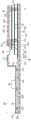
图5是详细示出根据实施例的真空绝热体的视图。FIG. 5 is a view showing in detail the vacuum heat insulator according to the embodiment.
图6是支撑单元与第一板构件之间的相互关系的视图,其示出了任一个边缘部。FIG. 6 is a view of the relationship between the support unit and the first plate member, showing either edge portion.
图7是示出通过比较图5中设置的真空绝缘体和图11中设置的真空绝缘体而获得的实验结果的视图。FIG. 7 is a view showing experimental results obtained by comparing the vacuum insulator set in FIG. 5 and the vacuum insulator set in FIG. 11 .
图8示出通过采用模拟方式来表示相对于真空压力的绝热性能的变化及气体传导率的变化的图形。FIG. 8 shows graphs representing changes in thermal insulation performance and changes in gas conductivity with respect to vacuum pressure by using a simulation method.
图9示出通过观察得到的、当使用支撑单元时真空绝热体的内部进行排气的过程随时间和压力而变化的图形。FIG. 9 shows a graph obtained by observation as a function of time and pressure in the process of evacuation of the inside of the vacuum insulator when the support unit is used.
图10示出通过比较真空压力和气体传导率得到的图形。Figure 10 shows a graph obtained by comparing vacuum pressure and gas conductivity.
图11示出真空绝热体的比较示例。FIG. 11 shows a comparative example of the vacuum insulator.
具体实施方式Detailed ways
现在将具体参考本公开的实施例,在附图中示出了这些实施例的示例。Reference will now be made in detail to the embodiments of the present disclosure, examples of which are illustrated in the accompanying drawings.
在优选实施例的以下详细描述中,参考了构成描述的一部分的附图,且其中借助示例示出可实施本公开的特定优选实施例。这些实施例被足够详细地描述,使得本领域技术人员能够实施本公开,并且应该理解的是,可运用其他实施例并且在没有背离本公开的精神或范围的情况下可进行逻辑结构、机械、电气和化学方面的改变。为了避免对于本领域技术人员实施本公开不必要的细节,该描述可省略本领域技术人员已知的某些信息。因此,下文的具体描述不应被认为是限制性的。In the following detailed description of the preferred embodiments, reference is made to the accompanying drawings, which form a part hereof, and in which specific preferred embodiments in which the disclosure may be practiced are shown by way of example. These embodiments are described in sufficient detail to enable those skilled in the art to practice the present disclosure, and it should be understood that other embodiments may be utilized and logical, structural, mechanical, Electrical and chemical changes. To avoid detail not necessary for those skilled in the art to practice the present disclosure, the description may omit certain information known to those skilled in the art. Therefore, the following detailed description should not be regarded as limiting.
在下文的描述中,术语“真空压力”是指低于大气压力的一定压力状态。此外,A的真空度大于B的真空度这样的表达是指A的真空压力小于B的真空压力。In the following description, the term "vacuum pressure" refers to a certain pressure state below atmospheric pressure. In addition, the expression that the vacuum degree of A is greater than the vacuum degree of B means that the vacuum pressure of A is smaller than the vacuum pressure of B.
图1是根据实施例的冰箱的立体图。FIG. 1 is a perspective view of a refrigerator according to an embodiment.
参考图1,冰箱1包括主体2和门3,主体2设有能够储存储备物品的空腔9,门3被设置为用于打开/关闭主体2。门3可以可旋转地或可移动地被设置为打开/关闭空腔9。空腔9可以提供冷藏室和冷冻室中的至少一个。Referring to FIG. 1 , the
提供构成将冷空气供应到空腔9中的冷冻循环的部件。特别地,这些部件包括用于压缩制冷剂的压缩机4、用于冷凝被压缩的制冷剂的冷凝器5、用于膨胀被冷凝的制冷剂的膨胀器6、以及用于蒸发被膨胀的制冷剂以带走热量的蒸发器7。作为典型结构,风扇可以被安装在邻近蒸发器7的位置处,并且从风扇吹出的流体可以穿过蒸发器7并接着被吹入空腔9中。通过调节风扇的吹出量和吹出方向、调节循环的制冷剂的量、或调节压缩机的压缩率来控制冷冻负荷,从而能够控制冷藏空间或冷冻空间。Components constituting a refrigeration cycle supplying cold air into the
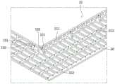
图2是示意性示出在冰箱的主体和门中使用的真空绝热体的视图。在图2中,示出主体侧真空绝热体和门侧真空绝热体,其中门侧真空绝热体处于前壁的一部分被移除的状态,主体侧真空绝热体处于顶壁和侧壁被移除的状态。此外,为了方便理解,示意性地示出抗传导片处的部分的截面。FIG. 2 is a view schematically showing a vacuum insulator used in a main body and a door of a refrigerator. In FIG. 2 , the main body side vacuum insulator and the door side vacuum insulator are shown, wherein the door side vacuum insulator is in a state where a part of the front wall is removed, and the main body side vacuum insulator is in a state where the top wall and side walls are removed status. In addition, to facilitate understanding, a section of a portion at the anti-conduction sheet is schematically shown.
参考图2,真空绝热体包括用于提供低温空间的壁的第一板构件10、用于提供高温空间的壁的第二板构件20、被限定为第一板构件10与第二板构件20之间的间隙部分的真空空间部50。另外,真空绝热体包括用于防止第一板构件10与第二板构件20之间的热传导的抗传导片60和63。设置用于密封第一板构件10和第二板构件20的密封部61,从而使真空空间部50处于密封状态。当真空绝热体被应用于制冷柜或加热柜时,第一板构件10可以被称为内壳体,第二板构件20可以被称为外壳体。容纳提供冷冻循环的部件的机器室8被放置在主体侧真空绝热体的下部后侧处,用于通过排出真空空间部50中的空气而形成真空状态的排气端口40被设置在真空绝热体的任一侧处。此外,还可以安装穿过真空空间部50的管路64,以便安装除霜水管线和电线。Referring to FIG. 2 , the vacuum insulator includes a
第一板构件10可以限定用于设置于其上的第一空间的壁的至少一部分。第二板构件20可以限定用于设置于其上的第二空间的壁的至少一部分。第一空间和第二空间可以被限定为具有不同温度的空间。这里,每个空间的壁不仅可以用作直接接触空间的壁,而且还可以用作不接触空间的壁。例如,该实施例的真空绝热体还可以被应用于还具有接触每个空间的单独的壁的产品。The
导致真空绝热体的绝热效果损失的热传递因素是:第一板构件10与第二板构件20之间的热传导、第一板构件10与第二板构件20之间的热辐射、以及真空空间部50的气体传导。The heat transfer factors that cause the loss of the insulating effect of the vacuum insulator are: heat conduction between the
在下文中,将提供被设置为减少与热传递因素相关的绝热损失的抗热单元。同时,该实施例的真空绝热体和冰箱不排除在真空绝热体的至少一侧处还设置有另一个绝热装置。因此,使用发泡加工等的绝热装置还可以被设置到真空绝热体的另一侧。In the following, a heat resistant unit arranged to reduce thermal insulation losses related to heat transfer factors will be provided. Meanwhile, the vacuum insulator and the refrigerator of this embodiment do not exclude that another thermal insulator is provided at at least one side of the vacuum insulator. Therefore, a heat insulating device using foam processing or the like can also be provided to the other side of the vacuum heat insulator.
图3是示出真空空间部的内部结构的多个实施例的视图。FIG. 3 is a view showing various embodiments of the internal structure of the vacuum space portion.
首先,参考图3a,真空空间部50被设置在具有与第一空间和第二空间不同的压力的第三空间中,优选地为真空状态,从而减少绝热损失。第三空间可以被设置为介于第一空间的温度与第二空间的温度之间的温度。由于第三空间被设置为处于真空状态的空间,因此由于与第一空间和第二空间之间的压力差对应的力,第一板构件10和第二板构件20接收在使它们彼此靠近的方向上收缩的力。因此,真空空间部50可以沿该真空空间部被减小的方向变形。在这种情况下,由于真空空间部50的收缩导致的热辐射量的增加、以及板构件10与20之间的接触导致的热传导量的增加,可能导致绝热损失。First, referring to Fig. 3a, the
可设置支撑单元30以减小真空空间部50的变形。支撑单元30包括杆31。杆31可以沿大致垂直于第一板构件10和第二板构件20的方向延伸,以便支撑第一板构件10与第二板构件20之间的距离。支撑板35可以附加地被设置到杆31的至少一个端部。支撑板35使至少两个杆31彼此连接,并且可以沿与第一板构件10和第二板构件20水平的方向延伸。支撑板35可以被设置为板状,或者可以被设置为格子状,使得其与第一板构件10或第二板构件20接触的面积减小,从而减少热传递。杆31和支撑板35在至少一个部分处彼此固定,以一起被插在第一板构件10与第二板构件20之间。支撑板35接触第一板构件10和第二板构件20中的至少一个,从而防止第一板构件10和第二板构件20的变形。此外,基于杆31的延伸方向,支撑板35的总截面面积被设置为大于杆31的总截面面积,使得通过杆31传递的热量可以通过支撑板35扩散。The
支撑单元30的材料可以包括从由PC、玻璃纤维PC、低释气PC、PPS和LCP组成的组中选择的树脂,以便获得高压缩强度、低释气和吸水性、低导热性、高温下的高压缩强度、以及优异的机械加工性。The material of the
将描述用于减少第一板构件10与第二板构件20之间通过真空空间部50的热辐射的抗辐射片32。第一板构件10和第二板构件20可以由能够防止腐蚀和提供足够强度的不锈钢材料制成。不锈钢材料具有0.16的相对高的辐射率,因此可传递大量的辐射热。此外,由树脂制成的支撑单元30具有比板构件低的辐射率,并且不完全被设置到第一板构件10和第二板构件20的内表面。因此,支撑单元30对辐射热没有很大影响。因此,抗辐射片32可以在真空空间部50的大部分区域上被设置为板状,以便集中于降低在第一板构件10与第二板构件20之间传递的辐射热。具有低辐射率的产品可以优选地被用作抗辐射片32的材料。在一个实施例中,具有0.02的辐射率的铝箔可以被用作抗辐射片32。由于使用一个抗辐射片不能充分地阻止辐射热的传递,因此至少两个抗辐射片32可以以一定距离设置,以便不互相接触。此外,至少一个抗辐射片可以被设置为其接触第一板构件10或第二板构件20的内表面的状态。The
参考图3b,通过支撑单元30保持板构件之间的距离,以及可在真空空间部50中填充多孔材料33。多孔材料33可以具有比第一板构件10和第二板构件20的不锈钢材料高的辐射率。但是,由于多孔材料33被填充在真空空间部50中,因此多孔材料33具有阻止辐射传热的高效率。Referring to FIG. 3 b , the distance between the plate members is maintained by the
在这个实施例中,可以在不使用抗辐射片32的情况下制造真空绝热体。In this embodiment, the vacuum insulator can be manufactured without using the
参考图3c,没有设置保持真空空间部50的支撑单元30。代替支撑单元30,多孔材料33被设置为由膜34环绕的状态。在这种情况下,多孔材料33可以被设置为被压缩的状态,以保持真空空间部50的间隙。膜34由例如PE材料制成,并且可以被设置为其中形成多个孔的状态。3c, the
在这个实施例中,可以在不使用支撑单元30的情况下制造真空绝热体。换言之,多孔材料33可以一起用作抗辐射片32和支撑单元30。In this embodiment, the vacuum insulator can be manufactured without using the
图4是示出抗传导片及其周边部分的多个实施例的视图。图2中简要地示出了抗传导片的结构,但应该参考图4详细理解。FIG. 4 is a view showing various embodiments of the anti-conduction sheet and its peripheral portion. The structure of the anti-conduction sheet is briefly shown in FIG. 2 , but should be understood in detail with reference to FIG. 4 .
首先,图4a中示出的抗传导片可以优选地被应用于主体侧真空绝热体。特别地,将第一板构件10和第二板构件20密封,以便使真空绝热体的内部真空。在这种情况下,由于两个板构件具有彼此不同的温度,因此热传递可以发生在两个板构件之间。抗传导片60被设置为防止两种不同类型的板构件之间的热传导。First, the anti-conduction sheet shown in Fig. 4a can be preferably applied to the main body side vacuum insulator. Specifically, the
抗传导片60可以设置有密封部61,抗传导片60的两端被密封于该密封部61处以限定用于第三空间的壁的至少一部分并保持真空状态。抗传导片60可以被设置为以微米为单位的薄箔,以便减少沿着用于第三空间的壁传导的热量。密封部61可以被设置为焊接部。就是说,抗传导片60以及板构件10和20可以彼此熔合。为了在抗传导片60与板构件10和20之间引起熔合作用,抗传导片60以及板构件10和20可以由相同的材料制成,并且不锈钢材料可以被用作该材料。密封部61不限于焊接部,并且可以通过诸如翘起(cocking)的工艺来提供。抗传导片60可以被设置为曲形形状。因此,抗传导片60的热传导距离被设置成比各个板构件的直线距离长,从而可以进一步减少热传导量。The
沿着抗传导片60发生温度变化。因此,为了阻止热量传导到抗传导片60的外部,在抗传导片60的外部处可以设置屏蔽部62,使得绝热作用发生。换言之,在冰箱中,第二板构件20具有高温,第一板构件10具有低温。此外,从高温到低温的热传导在抗传导片60中发生,因而抗传导片60的温度被突然改变。因此,当抗传导片60向其外部打开时,可极大地发生经过打开位置的热传递。为了减少热损失,屏蔽部62被设置在抗传导片60的外部。例如,当抗传导片60被暴露于低温空间和高温空间中的任一空间时,抗传导片60不会用作抗传导件(conductive resistor)及其暴露部分(这并非优选的)。Temperature changes occur along the
屏蔽部62可以被设置为与抗传导片60的外表面接触的多孔材料。屏蔽部62可以被设置为绝热结构,例如单独的衬垫,该屏蔽部被放置在抗传导片60的外部。屏蔽部62可以被设置为真空绝热体的一部分,该屏蔽部被设置在当主体侧真空绝热体相对于门侧真空绝热体关闭时面向相应的抗传导片60的位置处。为了减少甚至是在主体和门被打开时的热损失,屏蔽部62可以优选地被设置为多孔材料或单独的绝热结构。The shielding
图4b中示出的抗传导片可以优选地被应用于门侧真空绝热体。在图4b中,详细描述了与图4a所示不同的部分,并且相同的描述被应用于与图4a所示相同的部分。在抗传导片60的外侧还设置侧框架70。在侧框架70上可放置用于在门与主体之间进行密封的部件、排气过程所需的排气端口、用于真空维护的吸气端口等。这是因为这些部件便于安装在主体侧真空绝热体中,但这些部件的安装位置在门侧真空绝热体中是有限的。The anti-conduction sheet shown in Figure 4b can preferably be applied to the door-side vacuum insulation. In Fig. 4b, parts different from those shown in Fig. 4a are described in detail, and the same descriptions are applied to the same parts as shown in Fig. 4a. A
在门侧真空绝热体中,难以将抗传导片60放置在真空空间部的前端部处,即真空空间部的拐角侧部处。这是因为,与主体不同,门的拐角边缘部被暴露在外。更特别地,如果抗传导片60被放置在真空空间部的前端部处,则门的拐角边缘部暴露在外,因此存在要构造单独的绝热部以使抗传导片60隔热的缺点。In the door-side vacuum insulator, it is difficult to place the
图4c中示出的抗传导片可以优选地被安装在穿过真空空间部的管路中。在图4c中,详细描述了与图4a和图4b所示不同的部分,并且相同的描述被应用于与图4a和图4b所示相同的部分。具有与图4a所示相同的形状的抗传导片、优选地有褶皱的抗传导片63可以被设置在管路64的周边部分处。相应地,可以延长传热路径(heat transfer path),并且可以防止由压力差导致的变形。此外,可设置单独的屏蔽部,以提高抗传导片的绝热性能。The anti-conduction sheet shown in Fig. 4c may preferably be installed in the duct passing through the vacuum space. In Fig. 4c, parts different from those shown in Figs. 4a and 4b are described in detail, and the same descriptions are applied to the same parts as shown in Figs. 4a and 4b. An anti-conduction sheet, preferably a
将再次参考图4a描述第一板构件10与第二板构件20之间的传热路径。穿过真空绝热体的热量可以被分为:沿着真空绝热体(更特别地,抗传导片60)的表面传导的表面传导热①、沿着设置在真空绝热体内的支撑单元30传导的支撑件传导热②、通过真空空间部中的内部气体传导的气体传导热③、以及通过真空空间部传递的辐射传递热④。The heat transfer path between the
可根据多种设计尺寸而改变传递热。例如,可改变支撑单元而使第一板构件10和第二板构件20可以在没有变形的情况下承受真空压力,可改变真空压力,可改变板构件之间的距离,以及可改变抗传导片的长度。可根据分别由板构件提供的空间(第一空间和第二空间)之间的温度差而改变传递热。在一个实施例中,考虑到真空绝热体的总传热量小于由发泡聚氨酯构成的典型绝热结构的总传热量,已经发现真空绝热体的优选构造。在包括通过聚氨酯发泡形成的绝热结构的典型冰箱中,可提出19.6mW/mK的有效传热系数。The heat transfer can be varied according to various design dimensions. For example, the support unit can be changed so that the
通过对该实施例的真空绝热体的传热量进行对比分析,可以使气体传导热③的传热量最小。例如,气体传导热③的传热量可被控制为等于或小于总传热量的4%。被限定为表面传导热①和支撑件传导热②的总和的固体传导热的传热量最大。例如,固体传导热的传热量可以到达总传热量的75%。辐射传递热④的传热量小于固体传导热的传热量,但大于气体传导热③的传热量。例如,辐射传递热④的传热量可以占总传热量的约20%。By comparing and analyzing the heat transfer amount of the vacuum insulator of this embodiment, the heat transfer amount of the
根据这样的传热分布,表面传导热①、支撑件传导热②、气体传导热③和辐射传递热④的有效传热系数(eK:有效K)(W/mK)可以具有公式1的顺序。According to such a heat transfer distribution, the effective heat transfer coefficients (eK: effective K) (W/mK) of
【公式1】【Formula 1】
eK固体传导热>eK辐射传递热>eK气体传导热eKsolid conduction heat >eKradiation heat transfer >eKgas conduction heat
这里,有效传热系数(eK)是可以使用目标产品的形状和温度差测量的值。有效传热系数(eK)是可以通过测量热所传递到的至少一部分的总传热量和温度而获得的值。例如,使用可以在冰箱中定量测量的热源来测量热值(W),使用分别通过冰箱的门的边缘和主体传递的热来测量门的温度分布(K),以及传递热所通过的路径作为换算值(m)进行计算,从而评估有效传热系数。Here, the effective heat transfer coefficient (eK) is a value that can be measured using the shape and temperature difference of the target product. The effective heat transfer coefficient (eK) is a value that can be obtained by measuring the total amount of heat transfer and the temperature of at least a portion to which the heat is transferred. For example, the calorific value (W) is measured using a heat source that can be quantitatively measured in the refrigerator, the temperature distribution (K) of the door is measured using the heat transferred through the edge and the main body of the refrigerator door, respectively, and the path through which the heat is transferred as The conversion value (m) is calculated to evaluate the effective heat transfer coefficient.
整个真空绝热体的有效传热系数(eK)是通过k=QL/A△T给出的值。这里,Q表示热值(W)且可使用加热器的热值得到。A表示真空绝热体的截面面积(m2),L表示真空绝热体的厚度(m),以及△T表示温度差。The effective heat transfer coefficient (eK) of the entire vacuum insulator is the value given by k=QL/AΔT. Here, Q represents a calorific value (W) and can be obtained using the calorific value of a heater. A represents the cross-sectional area (m2 ) of the vacuum insulator, L represents the thickness (m) of the vacuum insulator, and ΔT represents the temperature difference.
对于表面传导热,传导热值(conductive calorific value)可以通过抗传导片60或63的进口与出口之间的温度差(△T)、抗传导片的截面面积(A)、抗传导片的长度(L)和抗传导片的热导率(k,抗传导片的热导率是材料的材料性质且可提前获得)获得。对于支撑件传导热,传导热值可以通过支撑单元30的进口与出口之间的温度差(△T)、支撑单元的截面面积(A)、支撑单元的长度(L)和支撑单元的热导率(k)获得。这里,支撑单元的热导率是材料的材料性质且可提前获得。通过从整个真空绝热体的传热量减去表面传导热和支撑件传导热可以得到气体传导热③和辐射传递热④的总和。通过显著降低真空空间部50的真空度,当不存在气体传导热时,通过评估辐射传递热可以获得气体传导热③与辐射传递热④的比率。For surface conduction heat, the conductive calorific value can be determined by the temperature difference (ΔT) between the inlet and the outlet of the
当真空空间部50内设有多孔材料时,多孔材料传导热⑤可以是支撑件传导热②和辐射传递热④的总和。多孔材料传导热⑤可以根据多个变量(包括多孔材料的种类、数量等)而变化。When a porous material is provided in the
根据一个实施例,由相邻杆31形成的几何中心与每个杆31所位于的点之间的温度差△T1可以优选地被设置为小于0.5℃。此外,由相邻杆31形成的几何中心与真空绝热体的边缘部之间的温度差△T2可以优选地被设置为小于0.5℃。在第二板构件20中,第二板的平均温度与经过抗传导片60或63的传热路径与第二板相遇的点处的温度之间的温度差可以是最大的。例如,当第二空间是比第一空间热的区域时,经过抗传导片的传热路径与第二板构件相遇的点处的温度变得最低。同样,当第二空间是比第一空间冷的区域时,经过抗传导片的传热路径与第二板构件相遇的点处的温度变得最高。According to one embodiment, the temperature difference ΔT1 between the geometric center formed by
这意味着,通过其他点传递的热量(除经过抗传导片的表面传导热之外)应该被控制,并且只有在表面传导热占最大传热量时才能实现满足真空绝热体的全部传热量。为此,抗传导片的温度变化可以被控制为大于板构件的温度变化。This means that the heat transfer through other points (other than the surface conduction heat through the anti-conduction sheet) should be controlled, and only when the surface conduction heat accounts for the maximum amount of heat transfer can the full amount of heat transfer for the vacuum insulator be achieved. For this reason, the temperature change of the anti-conduction sheet can be controlled to be larger than the temperature change of the plate member.
将描述构成真空绝热体的部件的物理特性。在真空绝热体中,通过真空压力将力施加于所有部件。因此,可优选地使用具有一定水平的强度(N/m2)的材料。The physical properties of the components constituting the vacuum insulator will be described. In a vacuum insulator, force is applied to all components by vacuum pressure. Therefore, a material having a certain level of strength (N/m2 ) may preferably be used.
在这样的情况下,板构件10和20以及侧框架70可以优选地由具有足够强度的材料制成,借助该材料使板构件10和20以及侧框架70不会受到均匀真空压力的损害。例如,当减少杆31的数量以限制支撑件传导热时,由于真空压力而发生板构件的变形,这可能对冰箱的外观有不良的影响。抗辐射片32可以优选地由具有低辐射率且可易于进行薄膜加工的材料制成。而且,抗辐射片32确保足够的强度,以避免因外部冲击而变形。支撑单元30被设置成具有足以支撑由真空压力产生的力并承受外部冲击的强度,并且具有机械加工性。抗传导片60可以优选地由具有薄板形状且可以承受真空压力的材料制成。In such a case, the
在一个实施例中,板构件、侧框架和抗传导片可以由具有相同强度的不锈钢材料制成。抗辐射片可以由具有与不锈钢材料相比较弱强度的铝制成。支撑单元可以由具有与铝相比较弱强度的树脂制成。In one embodiment, the plate members, the side frames and the anti-conduction sheet may be made of stainless steel material with the same strength. The anti-radiation sheet may be made of aluminum having weaker strength compared to stainless steel materials. The support unit may be made of resin having weaker strength than aluminum.
不同于从材料的角度来看强度的情况,需要从刚度的角度进行分析。刚度(N/m)是不会轻易变形的性质。虽然使用相同的材料,但其刚度可以根据其形状而变化。抗传导片60或63可以由具有一强度的材料制成,但材料的刚度优选地为低刚度以增加耐热性并使辐射热最小化,因为在施加真空压力时抗传导片均匀伸展而没有任何不平之处。抗辐射片32需要一定水平的刚度,以免由于变形而接触另一个部件。特别地,抗辐射片的边缘部可能由于抗辐射片的自身负荷导致的下垂而产生传导热。因此,需要一定水平的刚度。支撑单元30需要足以承受来自板构件的压缩应力和外部冲击的刚度。Unlike the case where strength is viewed from a material perspective, an analysis is required from a stiffness perspective. Stiffness (N/m) is a property that does not deform easily. Although the same material is used, its stiffness can vary depending on its shape. The
在一个实施例中,板构件和侧框架可以优选地具有最高的刚度,以便防止由真空压力导致的变形。支撑单元(特别是杆)可以优选地具有第二高的刚度。抗辐射片可以优选地具有比支撑单元低但比抗传导片高的刚度。抗传导片可以优选地由易于因真空压力而变形且具有最低刚度的材料制成。In one embodiment, the plate members and side frames may preferably have the highest stiffness in order to prevent deformation caused by vacuum pressure. The support unit, in particular the rod, may preferably have the second highest stiffness. The anti-radiation sheet may preferably have lower rigidity than the support unit but higher than the anti-conduction sheet. The anti-conduction sheet may preferably be made of a material that is easily deformed by vacuum pressure and has the lowest stiffness.
即使是在真空空间部50中填充多孔材料33时,抗传导片也可以优选地具有最低刚度,并且板构件和侧框架可以优选地具有最高的刚度。Even when the
图5是详细示出根据实施例的真空绝热体的视图。图5中示出的实施例可以优选地被应用于门侧真空绝热体,图4所示的真空绝热体中的图4b所示的真空绝热体的描述可以被应用于没有提供具体描述的部分。FIG. 5 is a view showing in detail the vacuum heat insulator according to the embodiment. The embodiment shown in FIG. 5 can be preferably applied to a door-side vacuum insulator, and the description of the vacuum insulator shown in FIG. 4b among the vacuum insulators shown in FIG. 4 can be applied to parts for which no specific description is provided .
参考图5,真空绝热体可以包括第一板构件10、第二板构件20、抗传导片60和侧框架70,这些是使真空空间部50能够与外部大气空间分开的部件。5, the vacuum insulator may include a
侧框架70形成为弯曲形状,并且可以被设置成使得当从真空绝热体的整个形状观察时,侧框架70的高度在外部、即边缘部处降低。侧框架70可以被设置成一形状,其中侧框架70与第二板构件20之间的间隙部被分成具有高的高度h1的部分和具有低的高度h2的部分。The
根据上述形状,侧框架70中具有较低高度的部分与真空绝热体外的其他部分相比,能够确保预定空间。由于侧框架70的高度差,可以设置附加安装部80,其中安装有诸如排气端口40或门铰接件等附加装置。因此,能够最大程度地确保产品(诸如由真空绝热体设置的冰箱)的内部体积,以提高绝热效果,并充分保证产品的功能。According to the above-described shape, a portion having a lower height in the
侧框架70的一端通过密封部61固定在抗传导片60上,侧框架70的另一端通过边缘部611固定到第二板构件20。边缘部611可以被设置为焊接部。真空空间部50延伸到边缘部611,从而提高绝热效果。One end of the
侧框架70提供一路径,通过抗传导片60的固体传导热量通过该路径。在冰箱中,通过抗传导片60的冷空气可以被传递到作为侧框架70与第二板构件20的侧部202之间的接触点的边缘部611。然而,冷空气不仅可通过抗传导片60减少,而且可在沿着侧框架70流动的同时也被充分地阻止。然而,尽管形成了露水,但是从外部不能观察到所形成的露水。The
具体地,第二板构件20包括前部201和相对于前部201弯曲的侧部202。然而,侧部202不暴露于外。因此,尽管在侧部202上形成了露水,但是用户不能用肉眼观察到所形成的露水,从而改善了用户的情绪。另外,在边缘部611被设置为焊接部时,因加热而不可避免地产生的焊接线从外部看不到,由此为用户改进了美感。可以容易地假定,侧部202形成真空空间部50的外壁。Specifically, the
尽管边缘部611除侧部202之外还设置在与侧部202相邻的前部201的拐角部分处,但边缘部可以不被用户观察到。作为另一示例,边缘部611可以被设置到第二板构件20的边缘部,以增加制造的便利性,同时不会被肉眼观察到。Although the
在图11中示出的比较示例中,通过由于侧框架70与前部201的接触部分处的温度降低而产生的露水形成区域71,能够容易地理解露水的形成。In the comparative example shown in FIG. 11 , the formation of dew can be easily understood by the
在冰箱中,通过抗传导片60的冷空气被传递到侧框架70,因此侧框架70具有比第一板构件10相对更高的温度。因此,当假定与第一杆311和第二杆312的另一端接触的第二板构件20的整个区域具有相同的温度时,与第二杆313的一端接触的侧框架70的温度可以被保持高于接触第一杆311的一端的第一板构件10的温度。因此,尽管第一杆311和第二杆313的长度彼此不同,但通过第一杆311的热传导可以与通过第二杆313的热传导保持相等。根据实验,已经发现具有1mm到2mm的高度的第二真空空间部502可以获得与具有10mm到20mm的高度的第一真空空间部501的绝热效果相等的足够的绝热效果。In the refrigerator, cool air passing through the
真空空间部50包括高度为h1的第一真空空间部501和高度为小于h1的h2的第二真空空间部502。第一真空空间部501和第二真空空间部502可以在真空状态下彼此连通。因此,能够减少单独形成真空空间部的制造过程的不便。The
第二支撑板352可以设置成在第二真空空间部502内延伸。另外,具有比第一杆311低的高度的第二杆312可以被设置到第二支撑板352。因此,第二真空空间部502可以由第二杆312保持。第二杆312可以与第二支撑板件352一起被设置为单一体。由于第一真空空间部501和第二真空空间部502的高度彼此不同,所以第一支撑板351可以延伸到第二真空空间部502。然而,本公开不限于此,第一支撑板351可以延伸到第二真空空间部502。尽管第一支撑板351没有延伸到第二真空空间部502,但是从第一板构件10传导到侧框架70的热流被抗传导片60阻止,因此,与通过第一杆311的热传导相比,通过第二杆312传导热可以获得相同的耐热效果。The
如上所述,抗传导片60具有阻止来自第一板构件10的热传递的目的。因此,在抗传导片60中沿着传热方向发生快速的温度变化。已经描述了,屏蔽部62被设置成阻止与温度的快速变化相对应地传递到真空绝热体的外部的热量。由于设置了真空空间部50,通过抗传导片60传递到真空绝热体内部的热量可以获得相对于对流和固体传导热的绝热效果,但是在阻止由辐射和气体传导引起的热传递方面较弱。为了解决这样的问题,甚至在抗传导片60的下侧可以放置抗辐射片32。As described above, the
特别地,抗辐射片32可以包括从第一支撑板351朝向第二支撑板352的方向依次设置的第一抗辐射片321、第二抗辐射片322和第三抗辐射片323。第一抗辐射片321可以通过第一支撑板351的端部延伸到抗传导片60的下侧。与第一抗辐射片321相比,第二抗辐射片322可向外延伸w2。与第二抗辐射片322相比,第三抗辐射片323可向外延伸w1。In particular, the
根据这样的构造,被设置为薄板的抗辐射片32可能因外部冲击和负荷而变形。这是因为,如果任何变形的抗辐射片与另一相邻的抗辐射片或抗传导片60接触,则发生直接热传导,因此产生大量的绝热损失。因此,即使当在第一抗辐射片321中发生预定变形时,第一抗辐射片321也不会延伸而抵达抗传导片60的中心。由于第二抗辐射片322不太可能接触抗传导片60,所以第二抗辐射片322可以借助穿过抗传导片60的中心而进一步向外延伸。然而,由于第二抗辐射片322很可能与另一相邻的抗辐射片接触,所以当抗辐射片是厚度为0.3mm到0.4mm的铝片时,从第一杆311延伸的第二抗辐射片322的长度优选地被限制为10mm到15mm。与第二抗辐射片322相比,第三抗辐射片323可以向外延伸w1。这是因为第三抗辐射片323由第二支撑板352支撑。According to such a configuration, the
在图5中,示出了抗辐射片32不在第二真空空间部502的内部延伸。然而,本公开不限于此,第三抗辐射片323的至少一部分被设置为接触第二支撑板352,第三抗辐射片可以延伸到第二真空空间部502的内部,由此减少辐射传导热。In FIG. 5 , it is shown that the
安装端部101被设置在第一板构件10的拐角处,肋102被设置在支撑单元30中。由于安装端部101由肋102引导,所以第一板构件10和支撑件单元30可以分别被放置在精确的位置。因此,能够提高部件之间的紧固精度。Mounting ends 101 are provided at the corners of the
图6是支撑单元与第一板构件之间的相互关系的视图,其示出了任一个边缘部。FIG. 6 is a view of the relationship between the support unit and the first plate member, showing either edge portion.
参照图6,可以设置这样的结构,其中设置到第二支撑板352的肋102和设置到第一板构件10的安装端部101彼此接触。因此,当第一板构件10被紧固到支撑单元30时或者当支撑单元30被紧固到第一板构件10时,第一板构件10与支撑单元30之间的位置可以被精确地放置。安装端部101和肋102具有彼此对应的结构,并且其尺寸和数量可根据第一板构件10和支撑单元30的尺寸而增大/减小。6 , a structure may be provided in which the
具有比第一杆311低的高度的第二杆312被设置在呈格栅形状的第二支撑板352的边缘部处。由此,能够维持第二真空空间部502的间隙。The
图7是示出将图5中提供的真空绝热体与图11中提供的真空绝热体进行比较而得到的实验结果的视图。FIG. 7 is a view showing experimental results obtained by comparing the vacuum insulator provided in FIG. 5 with the vacuum insulator provided in FIG. 11 .
参照图7,当真空绝热体被用于冰箱的门,并且冰箱执行标准操作时,测量真空绝热体的边缘部处的温度。进行实验得到的结果是,当使用典型的发泡聚氨酯时,真空绝热体的正面侧顶部(top side Top)处的温度为2.2℃,具有真空绝热体的中间高度的中部两侧处的温度为1.4℃,真空绝热体的底面侧底部(bottom side Bottom)处的温度为1.3℃,真空绝热体的中部中心(center Center)的温度为0.8℃。在图11中示出的比较示例中,真空绝热体的正面侧顶部处的温度为1.0℃,具有真空绝热体的中间高度的中部两侧处的温度为-0.3℃,真空绝热体的底面侧底部处的温度为-0.5℃,真空绝热体的中部中心的温度为1.3℃。根据比较示例,在正面侧顶部处、具有真空绝热体的中间高度的中部两侧处、以及底面侧底部处可能形成露水。特别地,可以看出,由于低于零度的低温,在外部空气温度为25℃、相对湿度为87%的条件下,在具有真空绝热体的中间高度的中部两侧处、以及底面侧底部处可能形成露水。Referring to FIG. 7 , when the vacuum insulator is used for the door of the refrigerator, and the refrigerator performs a standard operation, the temperature at the edge portion of the vacuum insulator is measured. As a result of conducting experiments, when a typical foamed polyurethane was used, the temperature at the top side top of the vacuum insulator was 2.2°C, and the temperature at both sides of the middle with the middle height of the vacuum insulator was 2.2°C. 1.4°C, the temperature at the bottom side bottom of the vacuum insulator was 1.3°C, and the temperature at the center center of the vacuum insulator was 0.8°C. In the comparative example shown in FIG. 11 , the temperature at the top of the front side of the vacuum insulator was 1.0° C., the temperature at both sides of the middle part with the middle height of the vacuum insulator was −0.3° C., and the bottom surface side of the vacuum insulator was −0.3° C. The temperature at the bottom was -0.5°C, and the temperature at the middle center of the vacuum insulator was 1.3°C. According to the comparative example, dew water may be formed at the top of the front side, at both sides of the middle with the middle height of the vacuum insulator, and at the bottom of the bottom side. In particular, it can be seen that due to the low temperature below zero, under the conditions of an outside air temperature of 25°C and a relative humidity of 87%, at both sides of the middle part with the middle height of the vacuum insulator, and at the bottom side of the bottom surface Dew may form.
另一方面,在本实施例中,真空绝热体的正面侧顶部处的温度为2.4℃,具有真空绝热体的中间高度的中部两侧处的温度为1.3℃,真空绝热体的底面侧底部处的温度为1.23℃,真空绝热体的中部中心的温度为1.3℃。根据本实施例,与使用典型的发泡聚氨酯的情况相比,能够获得更好的效果,且可以看出能够防止在门的前表面形成露水。On the other hand, in the present embodiment, the temperature at the top of the front side of the vacuum insulator is 2.4°C, the temperature at both sides of the middle part having the middle height of the vacuum insulator is 1.3°C, and the temperature at the bottom of the bottom side of the vacuum insulator is 1.3°C. The temperature of the vacuum insulator is 1.23℃, and the temperature of the middle center of the vacuum insulator is 1.3℃. According to the present embodiment, better effects can be obtained than in the case of using a typical foamed polyurethane, and it can be seen that the formation of dew on the front surface of the door can be prevented.
在下文中,真空压力优选地根据真空绝热体的内部状态来确定。如上所述,在真空绝热体内保持真空压力,以减少热传递。此时,容易预期到的是,真空压力优选地被保持得尽可能低,以便减少热传递。Hereinafter, the vacuum pressure is preferably determined according to the internal state of the vacuum insulator. As mentioned above, vacuum pressure is maintained within the vacuum insulation to reduce heat transfer. At this point, it is readily expected that the vacuum pressure is preferably kept as low as possible in order to reduce heat transfer.
真空空间部可以通过仅应用支撑单元30来阻止热传递。替代地,多孔材料33可以与支撑单元一起填充在真空空间部50中以阻止热传递。替代地,真空空间部可以不通过应用支撑单元而是通过应用多孔材料33来阻止热传递。The vacuum space portion can prevent heat transfer by applying only the
下面将描述仅应用支撑单元的情况。The case where only the support unit is applied will be described below.
图8示出通过采用模拟表示相对于真空压力的绝热性能的变化及气体传导率的变化的图形。FIG. 8 shows graphs representing changes in thermal insulation performance with respect to vacuum pressure and changes in gas conductivity by employing simulations.
参考图8,可以看出,随着真空压力的减小,即随着真空度的增加,在仅主体的情况(图形1)下或在主体和门连接在一起的情况(图形2)下的热负荷相较于通过发泡聚氨酯形成的典型产品的情况来说有所减小,从而提升绝热性能。但是,可以看出,绝热性能的提升程度逐渐降低。而且,可以看出,随着真空压力的减小,气体传导率(图形3)降低。但是,可以看出,虽然真空压力减小,但绝热性能与气体传导率所提升的比率逐渐降低。因此,优选地使真空压力减小为尽可能低。但是,获得过度的真空压力需要很长时间,并且由于过度使用吸气剂而消耗大量成本。在实施例中,从上述观点出发提出了最佳的真空压力。Referring to Figure 8, it can be seen that as the vacuum pressure decreases, i.e., as the vacuum level increases, in the case of the main body only (figure 1) or in the case of the main body and the door connected together (figure 2) The thermal load is reduced compared to the case of typical products formed by foaming polyurethane, thereby improving the thermal insulation properties. However, it can be seen that the degree of improvement in thermal insulation performance gradually decreases. Also, it can be seen that the gas conductivity (Figure 3) decreases as the vacuum pressure decreases. However, it can be seen that although the vacuum pressure decreases, the ratio of thermal insulation performance to gas conductivity improvement gradually decreases. Therefore, it is preferable to reduce the vacuum pressure as low as possible. However, it takes a long time to obtain excessive vacuum pressure and consumes a lot of cost due to excessive use of the getter. In the examples, the optimum vacuum pressure is proposed from the above-mentioned viewpoints.
图9示出通过观察得到的在使用支撑单元时真空绝热体的内部进行排气的过程随时间和压力变化的图形。FIG. 9 shows graphs of changes in time and pressure of the process of evacuation of the inside of the vacuum insulator when the support unit is used, obtained by observation.
参考图9,为了使真空空间部50处于真空状态,通过真空泵将真空空间部50中的气体排出,同时通过烘烤蒸发残留在真空空间部50的部件中的潜在气体。但是,如果真空压力到达一定水平或更高水平,则存在真空压力的水平不再增加的点(△t1)。此后,通过将真空空间部50与真空泵断开并将热量施加于真空空间部50来激活吸气剂(△t2)。如果吸气剂被激活,则真空空间部50中的压力在一段时间内减小,但随后归一化以保持一定水平的真空压力。在激活吸气剂之后保持在一定水平的真空压力大致为1.8×10⁻⁶托。Referring to FIG. 9 , in order to make the
在实施例中,即使通过操作真空泵排出气体也基本不再减小真空压力的点被设定为真空绝热体中使用的真空压力的最低极限,从而将真空空间部50的最小内部压力设定为1.8×10⁻⁶托。In the embodiment, the point at which the vacuum pressure is not substantially reduced even if the gas is exhausted by operating the vacuum pump is set as the lowest limit of the vacuum pressure used in the vacuum insulator, thereby setting the minimum internal pressure of the
图10示出通过比较真空压力与气体传导率得到的图形。Figure 10 shows a graph obtained by comparing vacuum pressure and gas conductivity.
参考图10,根据真空空间部50中的间隙的尺寸的关于真空压力的气体传导率被表示为有效传热系数(eK)的图形。当真空空间部50中的间隙具有2.76mm、6.5mm和12.5mm的三个尺寸时,测量有效传热系数(eK)。真空空间部50中的间隙被限定如下。当真空空间部50内存在抗辐射片32时,间隙是抗辐射片32与附接到其上的板构件之间的距离。当真空空间部50内不存在抗辐射片32时,间隙是第一板构件与第二板构件之间的距离。Referring to FIG. 10 , the gas conductivity with respect to the vacuum pressure according to the size of the gap in the
可以看出,由于间隙的尺寸在对应于0.0196W/mK的典型有效传热系数的点(设置为用于由发泡聚氨酯形成的绝热材料)处较小,因此真空压力为2.65×10-1托,即使是在间隙的尺寸为2.76mm时。同时,可以看出,即使真空压力减小,由气体传导热导致绝热效果降低的饱和的点是真空压力大致为4.5×10-3托的点。4.5×10-3托的真空压力可以被限定为由气体传导热导致绝热效果降低的饱和的点。而且,当有效传热系数为0.1W/mK时,真空压力为1.2×10-2托。It can be seen that the vacuum pressure is 2.65×10⁻¹ since the size of the gap is small at the point corresponding to a typical effective heat transfer coefficient of 0.0196 W/mK (set for thermal insulation formed from foamed polyurethane) support, even when the size of the gap is 2.76mm. At the same time, it can be seen that, even if the vacuum pressure is reduced, the saturated point at which the thermal insulation effect is reduced by the gas conduction heat is the point where the vacuum pressure is approximately 4.5×10⁻³ Torr. The vacuum pressure of 4.5×10⁻³ Torr can be defined as the point of saturation at which the thermal insulation effect is reduced due to the conduction heat of the gas. Also, when the effective heat transfer coefficient was 0.1 W/mK, the vacuum pressure was 1.2×10⁻² Torr.
当真空空间部50未设有支撑单元但设有多孔材料时,间隙的尺寸在几微米到几百微米的范围内。在这种情况下,辐射传热的量由于多孔材料而较小,即使是真空压力相对较高时,即当真空度低时。因此,适当的真空泵被用于调节真空压力。适用于相应的真空泵的真空压力大致为2.0×10⁻⁴托。而且,真空压力在由气体传导热导致绝热效果降低的饱和的点处大致为4.7×10⁻²托。而且,由气体传导热导致绝热效果降低达到0.0196W/mK的典型有效传热系数的压力为730托。When the
当支撑单元和多孔材料被一起设置在真空空间部中时,可以产生并使用真空压力,该真空压力是仅使用支撑单元时的真空压力与仅使用多孔材料时的真空压力之间的中间值。When the support unit and the porous material are provided together in the vacuum space portion, a vacuum pressure which is an intermediate value between the vacuum pressure when only the support unit is used and the vacuum pressure when only the porous material is used may be generated and used.
在本公开的描述中,真空绝热体的每个实施例中用于执行相同动作的部件可以通过适当地改变另一实施例的形状或尺寸而被应用于另一实施例。相应地,仍可以容易地提出另一实施例。例如,在详细的描述中,在适用为门侧真空绝热体的真空绝热体的情况下,通过适当地改变真空绝热体的形状和结构,真空绝热体可以被应用为主体侧真空绝热体。In the description of the present disclosure, components for performing the same action in each embodiment of the vacuum insulator may be applied to another embodiment by appropriately changing the shape or size of the other embodiment. Accordingly, another embodiment can easily be proposed. For example, in the detailed description, in the case of a vacuum insulator applied as a door-side vacuum insulator, the vacuum insulator can be applied as a main-body side vacuum insulator by appropriately changing the shape and structure of the vacuum insulator.
虽然已经参考多个示意性实施例来描述这些实施例,但应该理解的是,本领域技术人员可以设计将落入本公开的原理的精神和范围内的多种其他修改和实施例。更特别地,在本公开、附图和随附权利要求书的范围内,能够对主题组合布置的组成部分和/或布置作出多种变型和修改。除了对组成部分和/或布置的变型和修改之外,对于本领域技术人员而言,替代性用途也将是显而易见的。Although these embodiments have been described with reference to a number of illustrative embodiments thereof, it should be understood that numerous other modifications and embodiments can be devised by those skilled in the art that will fall within the spirit and scope of the principles of this disclosure. More particularly, various variations and modifications are possible in the component parts and/or arrangements of the subject combination arrangement within the scope of the disclosure, the drawings and the appended claims. In addition to variations and modifications in the component parts and/or arrangements, alternative uses will also be apparent to those skilled in the art.
工业实用性Industrial Applicability
本公开提出的真空绝热体可以优选地被应用于冰箱。但是,真空绝热体的应用并不局限于冰箱,还可以被应用于诸如低温制冷装置、加热装置和通风装置等多种装置中。The vacuum insulator proposed by the present disclosure may be preferably applied to a refrigerator. However, the application of the vacuum insulator is not limited to refrigerators, and can be applied to various devices such as low-temperature refrigeration devices, heating devices, and ventilation devices.
根据本公开,真空绝热体可以在工业上应用于多种绝热装置。绝热效果可以被提高,从而能够提升能量使用效率并增加装置的有效容积。According to the present disclosure, the vacuum insulator can be industrially applied to a variety of thermal insulation devices. The thermal insulation effect can be improved, which can improve the efficiency of energy use and increase the effective volume of the device.
Claims (10)
Priority Applications (2)
| Application Number | Priority Date | Filing Date | Title |
|---|---|---|---|
| CN202010670990.5ACN111854306A (en) | 2015-08-04 | 2016-08-02 | Vacuum insulator and refrigerator |
| CN202010669926.5ACN111854304A (en) | 2015-08-04 | 2016-08-02 | Vacuum insulator and refrigerator |
Applications Claiming Priority (3)
| Application Number | Priority Date | Filing Date | Title |
|---|---|---|---|
| KR10-2015-0110010 | 2015-08-04 | ||
| KR1020150110010AKR102466470B1 (en) | 2015-08-04 | 2015-08-04 | Vacuum adiabatic body and refrigerator |
| PCT/KR2016/008523WO2017023102A1 (en) | 2015-08-04 | 2016-08-02 | Vacuum adiabatic body and refrigerator |
Related Child Applications (2)
| Application Number | Title | Priority Date | Filing Date |
|---|---|---|---|
| CN202010670990.5ADivisionCN111854306A (en) | 2015-08-04 | 2016-08-02 | Vacuum insulator and refrigerator |
| CN202010669926.5ADivisionCN111854304A (en) | 2015-08-04 | 2016-08-02 | Vacuum insulator and refrigerator |
Publications (2)
| Publication Number | Publication Date |
|---|---|
| CN107850380A CN107850380A (en) | 2018-03-27 |
| CN107850380Btrue CN107850380B (en) | 2020-08-07 |
Family
ID=57943216
Family Applications (3)
| Application Number | Title | Priority Date | Filing Date |
|---|---|---|---|
| CN202010670990.5APendingCN111854306A (en) | 2015-08-04 | 2016-08-02 | Vacuum insulator and refrigerator |
| CN201680045949.0AActiveCN107850380B (en) | 2015-08-04 | 2016-08-02 | Vacuum insulators and refrigerators |
| CN202010669926.5APendingCN111854304A (en) | 2015-08-04 | 2016-08-02 | Vacuum insulator and refrigerator |
Family Applications Before (1)
| Application Number | Title | Priority Date | Filing Date |
|---|---|---|---|
| CN202010670990.5APendingCN111854306A (en) | 2015-08-04 | 2016-08-02 | Vacuum insulator and refrigerator |
Family Applications After (1)
| Application Number | Title | Priority Date | Filing Date |
|---|---|---|---|
| CN202010669926.5APendingCN111854304A (en) | 2015-08-04 | 2016-08-02 | Vacuum insulator and refrigerator |
Country Status (7)
| Country | Link |
|---|---|
| US (4) | US10788257B2 (en) |
| EP (2) | EP3971501B1 (en) |
| KR (2) | KR102466470B1 (en) |
| CN (3) | CN111854306A (en) |
| AU (2) | AU2016301918B2 (en) |
| ES (1) | ES2903040T3 (en) |
| WO (1) | WO2017023102A1 (en) |
Families Citing this family (13)
| Publication number | Priority date | Publication date | Assignee | Title |
|---|---|---|---|---|
| WO2017180145A1 (en)* | 2016-04-15 | 2017-10-19 | Whirlpool Corporation | Vacuum insulated refrigerator structure with three dimensional characteristics |
| KR102427466B1 (en) | 2017-08-01 | 2022-08-01 | 엘지전자 주식회사 | Vehicle, refrigerater for vehicle, and controlling method for refrigerator for vehicle |
| KR102529116B1 (en) | 2017-08-01 | 2023-05-08 | 엘지전자 주식회사 | Vacuum adiabatic body, fabrication method for the vacuum adibatic body, and refrigerating or warming apparatus insulated by the vacuum adiabatic body |
| KR102449175B1 (en) | 2017-08-01 | 2022-09-29 | 엘지전자 주식회사 | Vacuum insulator and refrigerator |
| KR102459784B1 (en) | 2017-08-01 | 2022-10-28 | 엘지전자 주식회사 | Vacuum adiabatic body and refrigerator |
| KR102449177B1 (en)* | 2017-08-01 | 2022-09-29 | 엘지전자 주식회사 | Vacuum insulator and refrigerator |
| KR102459786B1 (en) | 2017-08-16 | 2022-10-28 | 엘지전자 주식회사 | Vacuum adiabatic body and refrigerator |
| KR102529094B1 (en) | 2018-04-05 | 2023-05-08 | 엘지전자 주식회사 | Vacuum adiabatic body and refrigerator |
| KR20210007067A (en)* | 2019-07-09 | 2021-01-20 | 엘지전자 주식회사 | Vacuum adiabatic body, refrigerator, and fabricating method for the refrigerator |
| KR20210006740A (en)* | 2019-07-09 | 2021-01-19 | 엘지전자 주식회사 | Vacuum adiabatic body and refrigerator |
| KR20210006717A (en)* | 2019-07-09 | 2021-01-19 | 엘지전자 주식회사 | vacuum adiabatic module and refrigerator |
| KR102833241B1 (en) | 2019-07-31 | 2025-07-11 | 엘지전자 주식회사 | Vacuum adiabatic module, refrigerator, and fabrication method for the refrigerator |
| KR20220059312A (en)* | 2020-11-02 | 2022-05-10 | 엘지전자 주식회사 | Vacuum adiabatic body and fabrication method for the same |
Citations (5)
| Publication number | Priority date | Publication date | Assignee | Title |
|---|---|---|---|---|
| GB890372A (en)* | 1959-01-27 | 1962-02-28 | Union Carbide Corp | Vacuum panel insulation |
| CN102455105A (en)* | 2010-10-28 | 2012-05-16 | Lg电子株式会社 | refrigerator including vacuum space |
| DE102011014302A1 (en)* | 2011-03-17 | 2012-09-20 | Liebherr-Hausgeräte Ochsenhausen GmbH | Door element for refrigerator and/or freezer, has foam filled in interstice between vacuum insulation element and outer door panel |
| CN103649658A (en)* | 2011-07-14 | 2014-03-19 | Bsh博世和西门子家用电器有限公司 | Vacuum insulation element |
| CN104254749A (en)* | 2012-03-21 | 2014-12-31 | 株式会社东芝 | Refrigerator |
Family Cites Families (223)
| Publication number | Priority date | Publication date | Assignee | Title |
|---|---|---|---|---|
| US1413169A (en) | 1919-07-25 | 1922-04-18 | Charles B Lawton | Insulating construction |
| US1588707A (en) | 1924-07-23 | 1926-06-15 | Csiga Alexander | Vacuum ice chest |
| US1898977A (en) | 1928-09-07 | 1933-02-21 | Stator Refrigeration Inc | Vacuum insulation |
| US2000882A (en)* | 1928-09-07 | 1935-05-07 | Stator Refrigeration Inc | Insulating housing |
| US1845353A (en) | 1928-12-14 | 1932-02-16 | Virgil K Snell | Heat-insulating construction |
| US2550040A (en) | 1946-08-08 | 1951-04-24 | Clar Mottel | Selectively evacuated temperature regulated container |
| US2708774A (en) | 1949-11-29 | 1955-05-24 | Rca Corp | Multiple glazed unit |
| US2715976A (en) | 1952-04-28 | 1955-08-23 | Motor Products Corp | Breaker strip assembly |
| US2768046A (en) | 1952-07-09 | 1956-10-23 | Gen Electric | Insulating structures |
| DE956899C (en)* | 1952-10-28 | 1957-01-24 | Gen Electric | Heat isolator |
| US2729863A (en) | 1952-12-11 | 1956-01-10 | Gen Electric | Insulated cabinet |
| US2786241A (en) | 1954-06-02 | 1957-03-26 | Whirlpool Seeger Corp | Refrigerator door and gasket seal |
| US3091946A (en) | 1958-03-27 | 1963-06-04 | Gen Motors Corp | Cabinet and process for making same |
| US3161265A (en) | 1959-01-27 | 1964-12-15 | Union Carbide Corp | Vacuum panel insulation |
| US3370740A (en) | 1965-07-28 | 1968-02-27 | James H. Anderson | Vacuum jacketed joint construction |
| US3289423A (en) | 1965-11-30 | 1966-12-06 | Union Carbide Corp | Load support means for thermally insulated containers |
| US3520581A (en) | 1967-03-06 | 1970-07-14 | Giovanni Borghi | Cabinets for refrigerators and the like |
| US4056211A (en) | 1976-08-30 | 1977-11-01 | Rockwell International Corporation | Support and retention liner gasket |
| FR2379751A1 (en) | 1977-02-03 | 1978-09-01 | Balleyguier Alain | Thermal insulating material for gas storage tanks - has double wall sepd. by cross-pieces and between which there is a vacuum |
| DE2939878A1 (en) | 1979-10-02 | 1981-04-16 | Friedrich 5600 Wuppertal Hensberg | Thermal insulation wall panels - has vacuum sections with insulated supports and radiation shields |
| DE3121351A1 (en) | 1981-05-29 | 1982-12-16 | Genbee Osaka Kawaguchi | Spacer for a vacuum insulating device |
| IT1144387B (en)* | 1981-07-16 | 1986-10-29 | Indesit | INSULATION SYSTEM FOR A REFRIGERATOR |
| US4646934A (en) | 1986-01-21 | 1987-03-03 | Mcallister Ian R | Vacuum insulated shipping container and method |
| US4959111A (en) | 1986-08-19 | 1990-09-25 | Whirlpool Corporation | Heavy gas-filled multilayer insulation panels and method of manufacture thereof |
| US4822117A (en) | 1987-06-12 | 1989-04-18 | General Electric Company | Refrigerator case/liner interface and related components for automated assembly |
| KR970001913B1 (en) | 1988-07-12 | 1997-02-19 | 산덴 가부시기가이샤 | Cabinet with door seal |
| US5011729A (en) | 1989-11-15 | 1991-04-30 | Mcallister Ian R | Vacuum insulated panels with concave surfaces on the surface layers |
| US5185981A (en) | 1989-11-20 | 1993-02-16 | Perfil En Frio, S.A. | Abutment of insulating panels |
| US5018328A (en) | 1989-12-18 | 1991-05-28 | Whirlpool Corporation | Multi-compartment vacuum insulation panels |
| DE4016048C1 (en) | 1990-05-18 | 1991-10-24 | Messerschmitt-Boelkow-Blohm Gmbh, 8012 Ottobrunn, De | |
| JP2776646B2 (en)* | 1991-05-20 | 1998-07-16 | 株式会社クボタ | Structure of vacuum insulation box |
| JPH0510494A (en)* | 1991-07-03 | 1993-01-19 | Kubota Corp | End portion structure of vacuum insulation box |
| DE9204365U1 (en) | 1992-03-31 | 1992-07-02 | Liebherr-Hausgeraete Gmbh, 7955 Ochsenhausen | Wall element and/or door with low thermal transmittance |
| DE9204326U1 (en)* | 1992-03-31 | 1992-05-21 | Heinrich Wüstenberg GmbH, 5983 Balve | Device for covering installation shafts |
| DE69304701T2 (en) | 1992-06-08 | 1997-01-30 | Getters Spa | EVACUATED THERMAL INSULATION, IN PARTICULAR A COVER OF A DEWAR TANK OR ANY OTHER CRYOGENIC DEVICE |
| SE470463B (en) | 1992-09-10 | 1994-04-18 | Electrolux Res & Innovation | Refrigerator or freezer cabinets whose walls contain insulation and which are connected to a permanent vacuum source |
| DE4342948A1 (en) | 1993-12-16 | 1995-06-22 | Licentia Gmbh | Thermal insulation element |
| DE4342947A1 (en) | 1993-12-16 | 1995-06-22 | Licentia Gmbh | Wall element |
| JPH07234067A (en)* | 1994-02-21 | 1995-09-05 | Hitachi Ltd | Vacuum insulation doors for refrigerators, etc. |
| JPH07269779A (en) | 1994-03-28 | 1995-10-20 | Toshiba Corp | Method for manufacturing heat insulating casing and vacuum heat insulating panel |
| US5532034A (en) | 1994-12-06 | 1996-07-02 | Whirlpool Corporation | Getter system for vacuum insulation panel |
| KR19980703016A (en) | 1995-03-16 | 1998-09-05 | 휴스톤로버트엘 | Vacuum Insulated Panel with Mixed Wool Filler and Manufacturing Method Thereof |
| US5947479A (en) | 1995-03-31 | 1999-09-07 | John Crane Inc. | Mechanical seal with flexible metal diaphragm |
| CN1076460C (en) | 1995-04-13 | 2001-12-19 | 亨茨曼Ici化学品有限公司 | Non-planar evacuated insulating board, its manufacturing method and application |
| JPH09145241A (en) | 1995-11-20 | 1997-06-06 | Mitsubishi Chem Corp | Vacuum insulation |
| US5694789A (en) | 1996-01-16 | 1997-12-09 | Lg Electronics Inc. | Cam operated door seal for refrigerator |
| US5950450A (en) | 1996-06-12 | 1999-09-14 | Vacupanel, Inc. | Containment system for transporting and storing temperature-sensitive materials |
| DE19635214C2 (en) | 1996-08-30 | 1999-08-05 | Univ Dresden Tech | Multi-layer foil insulation material for thermal insulation and sound insulation |
| JP3876491B2 (en) | 1997-02-27 | 2007-01-31 | 三菱電機株式会社 | Vacuum insulation panel, method for manufacturing the same, and refrigerator using the same |
| GB2324798B (en) | 1997-05-01 | 1999-08-18 | Ici Plc | Open celled cellular polyurethane products |
| NL1005962C1 (en) | 1997-05-02 | 1998-11-03 | Rudolf Wolfgang Van Der Pol | Vacuum insulation panel |
| DE29809807U1 (en) | 1997-06-25 | 1998-11-19 | UVT GmbH, 74918 Angelbachtal | Vacuum insulation panel |
| GB9719612D0 (en) | 1997-09-09 | 1997-11-19 | Ultraframe Plc | Building elements |
| DE19745860A1 (en) | 1997-10-16 | 1999-06-17 | Bosch Siemens Hausgeraete | Insulating wall |
| DE19745861A1 (en) | 1997-10-16 | 1999-04-22 | Bosch Siemens Hausgeraete | Thermally insulated housing for refrigeration appliances |
| DE19745825A1 (en) | 1997-10-16 | 1999-04-22 | Bosch Siemens Hausgeraete | Thermally insulated cavity-walled case for e.g. Refrigerator |
| US6485805B1 (en) | 1998-01-15 | 2002-11-26 | Cabot Corporation | Multilayer insulation composite |
| JPH11211334A (en) | 1998-01-30 | 1999-08-06 | Hoshizaki Electric Co Ltd | Refrigerated display case |
| DE19803908A1 (en) | 1998-02-02 | 1999-08-05 | Thyssen Vakuum Isolationstechn | Evacuated thermal insulation panel with thermally insulated edges |
| JPH11335114A (en) | 1998-05-22 | 1999-12-07 | Kawasaki Steel Corp | Furnace body of heating furnace for purifying silicon |
| US6244458B1 (en) | 1998-07-09 | 2001-06-12 | Thermo Solutions, Inc. | Thermally insulated container |
| US6109712A (en) | 1998-07-16 | 2000-08-29 | Maytag Corporation | Integrated vacuum panel insulation for thermal cabinet structures |
| DE19840640A1 (en)* | 1998-09-05 | 2000-03-16 | Isovac Ingenieurgesellschaft M | Insulating housing, especially for refrigerator and/or energy storage device |
| DE19907182A1 (en) | 1999-02-19 | 2000-08-24 | Bsh Bosch Siemens Hausgeraete | Heat-insulating wall, like refrigerator door, refrigerator housing or similar has supported in front of membrane cover, protection profile fixed on inner and/or outer cladding, overlapping this as far as possible. |
| EP1045079B1 (en) | 1999-04-12 | 2007-10-03 | Isuzu Motors Limited | Heat insulating wall member, and method of manufacturing the same |
| DE19922295C1 (en) | 1999-05-14 | 2000-07-27 | Eurocopter Deutschland | Underfloor structure of fuselage cell for helicopter is connected with floor and outer fuselage shell, comprising interconnected longitudinal and crossbearers |
| DE29912917U1 (en)* | 1999-07-23 | 1999-11-18 | BSH Bosch und Siemens Hausgeräte GmbH, 81669 München | Insulating wall |
| TW508426B (en) | 1999-08-17 | 2002-11-01 | Toshiba Corp | Door opening device for storage apparatus |
| KR100402599B1 (en) | 1999-08-27 | 2003-10-22 | 주식회사 엘지이아이 | the structure of door gasket for refrigerator |
| KR100343719B1 (en) | 2000-01-14 | 2002-07-20 | 엘지전자주식회사 | Refrigerator door equipped with vacuum insulating material panel |
| JP3750534B2 (en) | 2001-02-20 | 2006-03-01 | いすゞ自動車株式会社 | Vacuum insulation and insulation panels |
| ITMI20010472A1 (en) | 2001-03-07 | 2002-09-07 | Ilpea Ind Spa | IMPROVED SEAL SET FOR REFRIGERATED AND SIMILAR FURNITURE WITH PLASTIC PROFILE |
| JP2002340280A (en) | 2001-05-18 | 2002-11-27 | Jamco Corp | Vacuum insulation block |
| US6684646B2 (en) | 2001-05-22 | 2004-02-03 | Integrated Biosystems, Inc. | Systems and methods for freezing, storing and thawing biopharmaceutical material |
| US20030062813A1 (en) | 2001-07-19 | 2003-04-03 | Cording Christopher R. | Energy-free refrigeration door and method for making the same |
| JP2003106760A (en) | 2001-09-27 | 2003-04-09 | Mitsubishi Corp | High heat insulation composite panel and structure using the same |
| US6598283B2 (en) | 2001-12-21 | 2003-07-29 | Cabot Corporation | Method of preparing aerogel-containing insulation article |
| CN1325864C (en) | 2002-03-13 | 2007-07-11 | 松下冷机株式会社 | Refrigerator |
| JP4216516B2 (en) | 2002-03-15 | 2009-01-28 | 象印マホービン株式会社 | Vacuum insulation panel |
| FR2839356B1 (en) | 2002-05-06 | 2004-10-15 | Cit Alcatel | MULTI-LAYER RIGID MATERIAL FOR THERMAL INSULATION |
| US7169459B2 (en) | 2002-05-15 | 2007-01-30 | L'garde, Inc. | Collapsible cellular insulation |
| AU2003238823A1 (en) | 2002-05-30 | 2003-12-19 | University Of Virginia Patent Foundation | Active energy absorbing cellular metals and method of manufacturing and using the same |
| TW593919B (en) | 2002-05-31 | 2004-06-21 | Matsushita Refrigeration | Vacuum heat insulating material and method for producing the same, and refrigerator using the vacuum heat insulating material |
| DE10225281C1 (en) | 2002-06-07 | 2003-11-06 | Dornier Gmbh | Structure element for a portable container, as a working space, has outer reinforced plastics claddings with rib spacers, to take insulation layers between them for a light weight with high mechanical strength |
| EP1378715B1 (en) | 2002-07-01 | 2009-03-04 | Whirlpool Corporation | A vacuum insulated refrigerator cabinet and method for assessing thermal conductivity thereof |
| JP2004044980A (en) | 2002-07-15 | 2004-02-12 | Toshiba Corp | Refrigerator door |
| US20040091688A1 (en) | 2002-11-11 | 2004-05-13 | Morio Gaku | Heat-resistant film base-material-inserted B-staged resin composition sheet excellent in adhesion to resin, multilayer board using the sheet and manufacturing process of the multilayer board |
| JP2004196411A (en) | 2002-12-20 | 2004-07-15 | Mitsubishi Chem Mkv Co | Insulated container |
| US20040226956A1 (en)* | 2003-05-14 | 2004-11-18 | Jeff Brooks | Cryogenic freezer |
| DE20321760U1 (en) | 2003-06-02 | 2009-08-13 | BSH Bosch und Siemens Hausgeräte GmbH | Door with double glazing and household appliance equipped with it |
| KR20060019576A (en) | 2003-07-04 | 2006-03-03 | 마쯔시다덴기산교 가부시키가이샤 | Vacuum Insulation Materials and Devices Using the Same |
| CN2700790Y (en) | 2003-09-24 | 2005-05-18 | 青岛亨达实业有限公司 | Glass door body of ice chest |
| KR100608869B1 (en) | 2003-12-24 | 2006-08-08 | 엘지전자 주식회사 | Manufacturing Method Of Refrigerator Cabinet |
| JP2005214372A (en) | 2004-02-02 | 2005-08-11 | Sangaku Renkei Kiko Kyushu:Kk | Sealed heat insulation structure and inter-heat insulation wall surface reinforcement method |
| ITTO20040455A1 (en) | 2004-07-05 | 2004-10-05 | Luca Gandini | VACUUM PANEL WITH HIGH THERMAL AND ACOUSTIC INSULATION |
| JP4179244B2 (en) | 2004-08-06 | 2008-11-12 | 三菱電機株式会社 | refrigerator |
| CN2748848Y (en) | 2004-09-02 | 2005-12-28 | 孟范中 | Vacuum heat insulation refrigerator |
| WO2006062080A1 (en) | 2004-12-07 | 2006-06-15 | Matsushita Electric Industrial Co., Ltd. | Vacuum heat insulating material, method of producing vacuum heat insulating material, and heat insulating box body using vacuum heat insulating material |
| KR20080011272A (en) | 2005-01-24 | 2008-02-01 | 서모백 리미티드 | Heat Insulated Panel Empty |
| DE102005021587A1 (en) | 2005-05-10 | 2006-11-16 | BSH Bosch und Siemens Hausgeräte GmbH | Refrigeration appliance and operating method for it |
| CN1896657A (en) | 2005-07-15 | 2007-01-17 | 乐金电子(天津)电器有限公司 | Door of refrigerator |
| US20070089989A1 (en) | 2005-09-02 | 2007-04-26 | William Hoagland | Conformable hydrogen indicating wrap to detect leaking hydrogen gas |
| KR100757450B1 (en) | 2005-11-16 | 2007-09-11 | 엘지전자 주식회사 | Vacuum Insulator and Insulation Structure of Refrigerator |
| KR100700612B1 (en) | 2006-01-03 | 2007-03-28 | 엘지전자 주식회사 | Combined structure of insulation panel of prefabricated refrigerator and prefabricated refrigerator having same |
| JP4417335B2 (en)* | 2006-02-17 | 2010-02-17 | 三菱電機株式会社 | Freezer refrigerator |
| US20070204648A1 (en) | 2006-03-03 | 2007-09-06 | Smale Jeffrey J | Step-down top hinge for refrigerator door with external dispenser |
| JP2008045580A (en) | 2006-08-11 | 2008-02-28 | Hitachi Appliances Inc | Vacuum insulation panel and equipment provided with the same |
| GB0701472D0 (en) | 2007-01-26 | 2007-03-07 | Rickards Michael J | A braced sound barrier vacuum panel |
| US7954301B2 (en) | 2007-03-16 | 2011-06-07 | Ball Aerospace & Technologies Corp. | Integrated multilayer insulation |
| JP2008249003A (en) | 2007-03-30 | 2008-10-16 | Hitachi Appliances Inc | Vacuum insulation panel and equipment provided with the same |
| JP2009024922A (en) | 2007-07-19 | 2009-02-05 | Hitachi Appliances Inc | refrigerator |
| JP4962399B2 (en) | 2007-09-05 | 2012-06-27 | パナソニック株式会社 | Gas adsorption device |
| US20090113899A1 (en) | 2007-11-02 | 2009-05-07 | John Dain | Systems and Methods for Ultra Low Temperature Storage |
| EP2226876B1 (en) | 2007-12-28 | 2018-04-11 | Panasonic Intellectual Property Management Co., Ltd. | Fuel cell separator and fuel cell provided with same |
| CN201191121Y (en) | 2007-12-29 | 2009-02-04 | 孟范中 | Evacuated insulation box for ice locker |
| ATE513467T1 (en) | 2008-03-26 | 2011-07-15 | Thomas Rotter | MULTI-LAYER HEAT-INSULATION WASHER ELEMENT |
| KR20090111632A (en) | 2008-04-22 | 2009-10-27 | 김현우 | UV Sterilizer for Bed Mattress |
| JP5198167B2 (en) | 2008-06-30 | 2013-05-15 | パナソニック株式会社 | Vacuum insulation box |
| WO2010007783A1 (en) | 2008-07-17 | 2010-01-21 | パナソニック株式会社 | Heat insulator, heat-insulating box object, heat-insulating door, and refrigerator |
| EP2538125A3 (en) | 2008-12-26 | 2013-02-20 | Mitsubishi Electric Corporation | Vacuum heat insulating material, heat insulating box using vacuum heat insulating material, refrigerator, refrigerating/air-conditioning apparatus, water heater, equipments, and manufacturing method of vacuum heat insulating material |
| US8329267B2 (en) | 2009-01-15 | 2012-12-11 | Eversealed Windows, Inc. | Flexible edge seal for vacuum insulating glazing units |
| KR101017969B1 (en) | 2009-02-26 | 2011-03-02 | 한국과학기술원 | Vacuum insulator |
| KR101041086B1 (en) | 2009-03-03 | 2011-06-14 | 한국과학기술원 | Vacuum insulator |
| KR101257361B1 (en) | 2009-05-04 | 2013-04-23 | 한국과학기술원 | Vacuum insulator and method for fabricating thereof |
| US8382219B2 (en) | 2009-05-11 | 2013-02-26 | Sub-Zero, Inc. | Installation system and door positioning device for appliances |
| KR101238999B1 (en) | 2009-06-19 | 2013-03-04 | (주)엘지하우시스 | Vacuum insulation panel |
| CN201428906Y (en) | 2009-07-09 | 2010-03-24 | 丁琪 | Supported vacuum double-glazed |
| KR20110015322A (en) | 2009-08-07 | 2011-02-15 | 엘지전자 주식회사 | Vacuum Insulator, Refrigerator with Vacuum Insulation and Manufacturing Method of Vacuum Insulation |
| KR101544453B1 (en) | 2009-08-07 | 2015-08-13 | 엘지전자 주식회사 | Core of Vacuum Insulator and Vacuum Insulator |
| KR101620397B1 (en) | 2009-08-07 | 2016-05-12 | 엘지전자 주식회사 | Vacuum insulation panel and refrigerator with vacuum insulation panel |
| KR101597554B1 (en) | 2009-08-07 | 2016-02-25 | 엘지전자 주식회사 | Refrigerator with vacuum insulation and vacuum insulation |
| JP5193980B2 (en) | 2009-09-28 | 2013-05-08 | 日立アプライアンス株式会社 | refrigerator |
| JP5575452B2 (en) | 2009-10-09 | 2014-08-20 | 株式会社東芝 | refrigerator |
| US8943770B2 (en) | 2009-11-20 | 2015-02-03 | Electrolux Home Products Pty Limited | Insulated panel and method of assembly |
| EP2333179A1 (en) | 2009-11-27 | 2011-06-15 | Iso-Pan International GmbH | Vacuum insulation panel |
| DE102009058789B4 (en) | 2009-12-18 | 2011-09-22 | Futech Gmbh | Heat-insulating glazing element and method for its production |
| US9217601B2 (en) | 2009-12-22 | 2015-12-22 | Lg Electronics Inc. | Refrigerator with a convertible compartment |
| CN102116554A (en) | 2010-01-04 | 2011-07-06 | Lg电子株式会社 | Refrigerator |
| KR101267733B1 (en) | 2010-03-04 | 2013-05-24 | (주)엘지하우시스 | Groove type vacuum heat insulation material |
| KR101775744B1 (en) | 2010-03-26 | 2017-09-19 | 파나소닉 주식회사 | Gas-adsorption device structure and method for using same |
| DE102011050473A1 (en) | 2010-05-18 | 2011-11-24 | Viktor Schatz | Discontinuous radiation suppression unit for suppressing heat transfer in e.g. manufacturing evacuated rimless composite system utilized in e.g. roof wall, has support elements arranged in spacer arrangement |
| CN102313432A (en) | 2010-05-28 | 2012-01-11 | 株式会社东芝 | Insulated enclosures for food storage |
| CN102261470B (en) | 2010-05-28 | 2016-02-10 | 博西华家用电器有限公司 | Sealing system and there are the household electrical appliance of this sealing system |
| US20110296797A1 (en) | 2010-06-02 | 2011-12-08 | Stark David H | Two-piece hermetic seal bellows for single-side placement on an insulating glass unit or highly insulating vacuum glass unit |
| DE102010031249A1 (en) | 2010-07-12 | 2012-01-12 | BSH Bosch und Siemens Hausgeräte GmbH | Housing component for a refrigeration device |
| KR101068459B1 (en) | 2010-07-29 | 2011-09-28 | 주식회사엑스엘 | Vacuum Insulation Panel |
| CN201764779U (en) | 2010-09-02 | 2011-03-16 | 许春钢 | Filling material for refrigerating device heat insulation |
| DE102010040557A1 (en) | 2010-09-10 | 2012-03-15 | BSH Bosch und Siemens Hausgeräte GmbH | Vacuum body for a refrigeration device |
| CN103189696B (en) | 2010-10-11 | 2015-05-27 | Lg电子株式会社 | Vacuum insulation glass panel and refrigerator having the same |
| JP5743483B2 (en) | 2010-10-20 | 2015-07-01 | 株式会社東芝 | Insulation cabinet |
| KR101898487B1 (en) | 2010-10-28 | 2018-10-04 | 엘지전자 주식회사 | A refrigerator comprising a vaccum space |
| KR101147779B1 (en) | 2010-10-28 | 2012-05-25 | 엘지전자 주식회사 | A refrigerator comprising a vaccum space |
| FR2969739B1 (en) | 2010-12-22 | 2013-02-15 | Georges Marguerite | THERMAL THERMAL INSULATION DEVICE HAVING HIGH PERFORMANCE |
| WO2012090566A1 (en) | 2010-12-27 | 2012-07-05 | 旭化成ケミカルズ株式会社 | Heat insulation material and production method for same |
| CN102116402A (en) | 2011-01-04 | 2011-07-06 | 合肥美的荣事达电冰箱有限公司 | Vacuum thermal insulation component and manufacturing method thereof, as well as refrigeration device |
| JP2012211721A (en) | 2011-03-31 | 2012-11-01 | Hitachi Appliances Inc | Refrigerator |
| US8881398B2 (en) | 2011-05-26 | 2014-11-11 | General Electric Company | Method and apparatus for insulating a refrigeration appliance |
| JP5931355B2 (en) | 2011-06-09 | 2016-06-08 | 株式会社東芝 | Heat insulation box |
| KR20120140392A (en) | 2011-06-21 | 2012-12-31 | 삼성전자주식회사 | Refrigerator |
| JP5890973B2 (en) | 2011-06-24 | 2016-03-22 | 株式会社松田技術研究所 | Vacuum insulation panel |
| KR101808568B1 (en) | 2011-08-12 | 2017-12-13 | 삼성전자주식회사 | Refrigerator |
| WO2013031234A1 (en) | 2011-08-31 | 2013-03-07 | パナソニック株式会社 | Refrigerator and vacuum insulation material for same |
| EP2584297A3 (en) | 2011-10-21 | 2017-09-27 | Samsung Electronics Co., Ltd | Refrigerator and Door for the Same |
| KR101832763B1 (en)* | 2011-11-02 | 2018-02-28 | 엘지전자 주식회사 | A refrigerator comprising a vacuum space |
| US9528749B2 (en) | 2011-11-02 | 2016-12-27 | Lg Electronics Inc. | Refrigerator |
| KR101861830B1 (en) | 2011-11-02 | 2018-05-29 | 엘지전자 주식회사 | A refrigerator comprising a vacuum space |
| KR101861831B1 (en)* | 2011-11-02 | 2018-05-29 | 엘지전자 주식회사 | A refrigerator comprising a vacuum space |
| JP2015507587A (en) | 2011-11-16 | 2015-03-12 | エルジー・ハウシス・リミテッドLg Hausys,Ltd. | Vacuum glass panel with getter filler and method of manufacturing the same |
| KR20130057619A (en) | 2011-11-24 | 2013-06-03 | (주)엘지하우시스 | Vacuum adiabatic material of blocking radiant heat |
| JP5978520B2 (en) | 2011-12-06 | 2016-08-24 | 東芝ライフスタイル株式会社 | Heat insulation box |
| JP5860685B2 (en)* | 2011-12-06 | 2016-02-16 | 株式会社東芝 | Insulation cabinet |
| DE102012100490A1 (en) | 2012-01-23 | 2013-07-25 | Götz von Waldeyer-Hartz | Thermal wall for refrigerated vehicles and large size freezer cabinets, has coating layer with filler material and spacers made of polyurethane foam, and are arranged on folds to lock covering layers parallel to vacuum insulation layer core |
| US9205368B2 (en) | 2012-03-21 | 2015-12-08 | Panasonic Intellectual Property Management Co., Ltd. | Gas adsorbing device and hollow body housing the same |
| JP6108180B2 (en) | 2012-03-23 | 2017-04-05 | パナソニックIpマネジメント株式会社 | Vacuum heat insulating material and heat insulating housing using the same |
| WO2013146286A1 (en) | 2012-03-26 | 2013-10-03 | 三菱電機株式会社 | Heat insulating box, and refrigerator and hot-water storage device each comprising heat insulating box |
| US9182158B2 (en) | 2013-03-15 | 2015-11-10 | Whirlpool Corporation | Dual cooling systems to minimize off-cycle migration loss in refrigerators with a vacuum insulated structure |
| US9071907B2 (en)* | 2012-04-02 | 2015-06-30 | Whirpool Corporation | Vacuum insulated structure tubular cabinet construction |
| US20130257257A1 (en) | 2012-04-02 | 2013-10-03 | Whirlpool Corporation | Method to create vacuum insulated cabinets for refrigerators |
| KR101410459B1 (en) | 2012-05-02 | 2014-06-27 | 삼성전자주식회사 | Refrigerator And Method Of Manufacturing Door Thereof |
| KR20140009647A (en) | 2012-07-12 | 2014-01-23 | 삼성전자주식회사 | Refrigerator and manufacturing method |
| CN103575038A (en) | 2012-08-02 | 2014-02-12 | 开利公司 | Frame and refrigerating device |
| JP6178055B2 (en) | 2012-08-20 | 2017-08-09 | 東芝ライフスタイル株式会社 | refrigerator |
| JP6091825B2 (en) | 2012-09-25 | 2017-03-08 | 東芝ライフスタイル株式会社 | refrigerator |
| KR20140047360A (en) | 2012-10-12 | 2014-04-22 | 동부대우전자 주식회사 | Refrigerator for preventing coagulation of door gasket |
| KR102025177B1 (en) | 2012-11-09 | 2019-09-26 | 삼성전자주식회사 | Refrigerator and method of making the inner door thereof |
| KR101565420B1 (en)* | 2012-12-13 | 2015-11-05 | 엘지전자 주식회사 | A refrigerator comprising a vacuum space |
| DE102012223539A1 (en) | 2012-12-18 | 2014-06-18 | BSH Bosch und Siemens Hausgeräte GmbH | Door for a household refrigerating appliance with a vacuum insulation element with molded bowls and household refrigerating appliance |
| RU129188U1 (en) | 2012-12-19 | 2013-06-20 | Федеральное государственное бюджетное образовательное учреждение высшего профессионального образования "Самарский государственный университет путей сообщения" (СамГУПС) | THERMAL INSULATION PRODUCT |
| CN203095854U (en) | 2013-01-25 | 2013-07-31 | 李梦琪 | Insulating colored crystal glass and freezer |
| US10179686B2 (en) | 2013-02-01 | 2019-01-15 | Sharp Kabushiki Kaisha | Storage container with heat storage material that provides heat to shelf included in storage container |
| EP2765375B1 (en) | 2013-02-06 | 2018-09-12 | Samsung Electronics Co., Ltd | Vacuum insulation material, insulation case unit, and refrigerator |
| KR102004470B1 (en) | 2013-04-01 | 2019-10-17 | 엘지전자 주식회사 | Refrigerator |
| KR101728196B1 (en) | 2013-04-26 | 2017-04-18 | 엘지전자 주식회사 | Refrigerator |
| KR101494077B1 (en) | 2013-04-30 | 2015-02-16 | 한국과학기술원 | Edge-sealing method and vacuum exhauster of vacuum insulation glass for sustainable use |
| KR20140137108A (en) | 2013-05-22 | 2014-12-02 | 엘지전자 주식회사 | refrigerator and manufacturing method thereof |
| CH708320B1 (en) | 2013-07-11 | 2017-04-28 | Seven-Air Gebr Meyer Ag | Heat-insulating, pressure-resistant wall. |
| KR102163292B1 (en) | 2013-07-26 | 2020-10-08 | 삼성전자주식회사 | Vacuum heat insulating material and refrigerator including the same |
| CN104344653A (en) | 2013-09-27 | 2015-02-11 | 海尔集团公司 | Refrigerator |
| CA2958414C (en) | 2013-10-18 | 2021-11-16 | Eversealed Windows, Inc. | Edge seal assemblies for hermetic insulating glass units and vacuum insulating glass units |
| JP6571911B2 (en) | 2013-10-22 | 2019-09-04 | 東芝ライフスタイル株式会社 | Refrigerator door |
| KR101752669B1 (en) | 2013-12-10 | 2017-06-30 | 삼성전자주식회사 | Vacuum heat insulating material and refrigerator including the same |
| JP6244195B2 (en) | 2013-12-19 | 2017-12-06 | 日立アプライアンス株式会社 | refrigerator |
| CN104746690A (en) | 2013-12-25 | 2015-07-01 | 戴长虹 | Double-vacuum-layer metal vacuum composite plate with edge sealed by seal strip and manufacturing method thereof |
| US9574819B2 (en)* | 2014-01-07 | 2017-02-21 | Samsung Electronics Co., Ltd. | Refrigerator |
| US9463918B2 (en) | 2014-02-20 | 2016-10-11 | Aarne H. Reid | Vacuum insulated articles and methods of making same |
| DE102014210473A1 (en) | 2014-06-03 | 2015-12-03 | BSH Hausgeräte GmbH | Door for a household refrigerating appliance with a vacuum insulation element and household refrigerating appliance |
| DE102014210472A1 (en) | 2014-06-03 | 2015-12-03 | BSH Hausgeräte GmbH | Door for a household appliance and household appliance |
| EP2975345B1 (en) | 2014-07-16 | 2019-01-02 | LG Electronics Inc. | Refrigerator door and manufacturing method of the same |
| KR102366410B1 (en) | 2014-10-16 | 2022-02-23 | 삼성전자주식회사 | Refrigerator and vacuum insulation module thereof |
| KR102222572B1 (en) | 2014-10-16 | 2021-03-05 | 삼성전자주식회사 | Refrigerator |
| JP6427675B2 (en) | 2014-12-19 | 2018-11-21 | ダウ グローバル テクノロジーズ エルエルシー | Vacuum vessel |
| KR101758277B1 (en) | 2015-06-04 | 2017-07-14 | 엘지전자 주식회사 | Refrigerater |
| KR102426183B1 (en) | 2015-06-05 | 2022-07-29 | 엘지전자 주식회사 | Refrigerator |
| WO2016208193A1 (en) | 2015-06-24 | 2016-12-29 | パナソニックIpマネジメント株式会社 | Gas-adsorbing device and evacuated insulating material using same |
| US9441779B1 (en) | 2015-07-01 | 2016-09-13 | Whirlpool Corporation | Split hybrid insulation structure for an appliance |
| KR102456642B1 (en) | 2015-08-03 | 2022-10-19 | 엘지전자 주식회사 | Vacuum adiabatic body and refrigerator |
| KR102442069B1 (en) | 2015-10-19 | 2022-09-13 | 삼성전자주식회사 | Refrigerator and its manufacturing method |
| JP2017106526A (en) | 2015-12-09 | 2017-06-15 | パナソニックIpマネジメント株式会社 | Vacuum heat insulation body, heat insulation equipment including the same, and manufacturing method of vacuum heat insulation body |
| US9752818B2 (en) | 2015-12-22 | 2017-09-05 | Whirlpool Corporation | Umbilical for pass through in vacuum insulated refrigerator structures |
| JP6593596B2 (en) | 2016-03-02 | 2019-10-23 | パナソニックIpマネジメント株式会社 | Vacuum heat insulating body, heat insulating device including the same, and method for manufacturing vacuum heat insulating body |
| EP3452766B1 (en) | 2016-05-03 | 2023-04-19 | Whirlpool Corporation | Refrigerator appliance with a vacuum insulation and a hinge support |
| US10830527B2 (en) | 2016-08-30 | 2020-11-10 | Whirlpool Corporation | Hermetically sealed overmolded plastic thermal bridge breaker with refrigerator cabinet liner and wrapper for vacuum insulation |
| CN108354755A (en) | 2018-03-22 | 2018-08-03 | 周少华 | A kind of examination couch of the Neurology inspection with automatic disinfecting function |
- 2015
- 2015-08-04KRKR1020150110010Apatent/KR102466470B1/enactiveActive
- 2016
- 2016-08-02CNCN202010670990.5Apatent/CN111854306A/enactivePending
- 2016-08-02EPEP21203522.4Apatent/EP3971501B1/enactiveActive
- 2016-08-02EPEP16833338.3Apatent/EP3332197B1/enactiveActive
- 2016-08-02USUS15/749,146patent/US10788257B2/enactiveActive
- 2016-08-02ESES16833338Tpatent/ES2903040T3/enactiveActive
- 2016-08-02AUAU2016301918Apatent/AU2016301918B2/enactiveActive
- 2016-08-02CNCN201680045949.0Apatent/CN107850380B/enactiveActive
- 2016-08-02CNCN202010669926.5Apatent/CN111854304A/enactivePending
- 2016-08-02WOPCT/KR2016/008523patent/WO2017023102A1/ennot_activeCeased
- 2020
- 2020-01-29AUAU2020200641Apatent/AU2020200641B2/enactiveActive
- 2020-07-29USUS16/942,262patent/US11365931B2/enactiveActive
- 2022
- 2022-05-20USUS17/749,679patent/US12281840B2/enactiveActive
- 2022-11-08KRKR1020220147819Apatent/KR102593895B1/enactiveActive
- 2025
- 2025-03-10USUS19/074,978patent/US20250207843A1/enactivePending
Patent Citations (5)
| Publication number | Priority date | Publication date | Assignee | Title |
|---|---|---|---|---|
| GB890372A (en)* | 1959-01-27 | 1962-02-28 | Union Carbide Corp | Vacuum panel insulation |
| CN102455105A (en)* | 2010-10-28 | 2012-05-16 | Lg电子株式会社 | refrigerator including vacuum space |
| DE102011014302A1 (en)* | 2011-03-17 | 2012-09-20 | Liebherr-Hausgeräte Ochsenhausen GmbH | Door element for refrigerator and/or freezer, has foam filled in interstice between vacuum insulation element and outer door panel |
| CN103649658A (en)* | 2011-07-14 | 2014-03-19 | Bsh博世和西门子家用电器有限公司 | Vacuum insulation element |
| CN104254749A (en)* | 2012-03-21 | 2014-12-31 | 株式会社东芝 | Refrigerator |
Also Published As
| Publication number | Publication date |
|---|---|
| CN111854306A (en) | 2020-10-30 |
| EP3332197A4 (en) | 2019-04-03 |
| AU2016301918B2 (en) | 2019-10-31 |
| US20180224194A1 (en) | 2018-08-09 |
| AU2020200641B2 (en) | 2021-11-04 |
| US20200363123A1 (en) | 2020-11-19 |
| KR20170016647A (en) | 2017-02-14 |
| KR20220153561A (en) | 2022-11-18 |
| WO2017023102A1 (en) | 2017-02-09 |
| US11365931B2 (en) | 2022-06-21 |
| KR102466470B1 (en) | 2022-11-11 |
| US12281840B2 (en) | 2025-04-22 |
| CN107850380A (en) | 2018-03-27 |
| KR102593895B1 (en) | 2023-10-26 |
| EP3971501B1 (en) | 2024-07-24 |
| ES2903040T3 (en) | 2022-03-30 |
| EP3332197A1 (en) | 2018-06-13 |
| US10788257B2 (en) | 2020-09-29 |
| EP3332197B1 (en) | 2021-12-01 |
| AU2020200641A1 (en) | 2020-02-20 |
| EP3971501A1 (en) | 2022-03-23 |
| US20250207843A1 (en) | 2025-06-26 |
| AU2016301918A1 (en) | 2018-02-22 |
| CN111854304A (en) | 2020-10-30 |
| US20220316791A1 (en) | 2022-10-06 |
Similar Documents
| Publication | Publication Date | Title |
|---|---|---|
| CN107850375B (en) | Vacuum insulators and refrigerators | |
| CN107923698B (en) | Vacuum insulator and refrigerator | |
| CN112629134B (en) | Vacuum heat insulator | |
| CN107850380B (en) | Vacuum insulators and refrigerators | |
| CN107923702B (en) | Vacuum insulator and refrigerator | |
| CN113266983B (en) | Vacuum insulator and refrigerator | |
| CN107850379B (en) | Vacuum insulators and refrigerators | |
| CN107850378B (en) | Vacuum insulators and refrigerators | |
| CN107850376B (en) | Vacuum insulator and refrigerator | |
| CN107850382A (en) | Vacuum insulation element and refrigerator | |
| CN107923700A (en) | Vacuum Insulators and Refrigerators |
Legal Events
| Date | Code | Title | Description |
|---|---|---|---|
| PB01 | Publication | ||
| PB01 | Publication | ||
| SE01 | Entry into force of request for substantive examination | ||
| SE01 | Entry into force of request for substantive examination | ||
| GR01 | Patent grant | ||
| GR01 | Patent grant |