CN107849863B - Elastic sliding friction joint - Google Patents
Elastic sliding friction jointDownload PDFInfo
- Publication number
- CN107849863B CN107849863BCN201680037527.9ACN201680037527ACN107849863BCN 107849863 BCN107849863 BCN 107849863BCN 201680037527 ACN201680037527 ACN 201680037527ACN 107849863 BCN107849863 BCN 107849863B
- Authority
- CN
- China
- Prior art keywords
- sliding connection
- sliding
- elements
- relative
- movement
- Prior art date
- Legal status (The legal status is an assumption and is not a legal conclusion. Google has not performed a legal analysis and makes no representation as to the accuracy of the status listed.)
- Active
Links
Images


Classifications
- E—FIXED CONSTRUCTIONS
- E04—BUILDING
- E04H—BUILDINGS OR LIKE STRUCTURES FOR PARTICULAR PURPOSES; SWIMMING OR SPLASH BATHS OR POOLS; MASTS; FENCING; TENTS OR CANOPIES, IN GENERAL
- E04H9/00—Buildings, groups of buildings or shelters adapted to withstand or provide protection against abnormal external influences, e.g. war-like action, earthquake or extreme climate
- E04H9/02—Buildings, groups of buildings or shelters adapted to withstand or provide protection against abnormal external influences, e.g. war-like action, earthquake or extreme climate withstanding earthquake or sinking of ground
- E04H9/021—Bearing, supporting or connecting constructions specially adapted for such buildings
- E—FIXED CONSTRUCTIONS
- E04—BUILDING
- E04B—GENERAL BUILDING CONSTRUCTIONS; WALLS, e.g. PARTITIONS; ROOFS; FLOORS; CEILINGS; INSULATION OR OTHER PROTECTION OF BUILDINGS
- E04B1/00—Constructions in general; Structures which are not restricted either to walls, e.g. partitions, or floors or ceilings or roofs
- E04B1/36—Bearings or like supports allowing movement
- E—FIXED CONSTRUCTIONS
- E04—BUILDING
- E04B—GENERAL BUILDING CONSTRUCTIONS; WALLS, e.g. PARTITIONS; ROOFS; FLOORS; CEILINGS; INSULATION OR OTHER PROTECTION OF BUILDINGS
- E04B1/00—Constructions in general; Structures which are not restricted either to walls, e.g. partitions, or floors or ceilings or roofs
- E04B1/38—Connections for building structures in general
- E04B1/388—Separate connecting elements
- E—FIXED CONSTRUCTIONS
- E04—BUILDING
- E04B—GENERAL BUILDING CONSTRUCTIONS; WALLS, e.g. PARTITIONS; ROOFS; FLOORS; CEILINGS; INSULATION OR OTHER PROTECTION OF BUILDINGS
- E04B1/00—Constructions in general; Structures which are not restricted either to walls, e.g. partitions, or floors or ceilings or roofs
- E04B1/62—Insulation or other protection; Elements or use of specified material therefor
- E04B1/92—Protection against other undesired influences or dangers
- E04B1/98—Protection against other undesired influences or dangers against vibrations or shocks; against mechanical destruction, e.g. by air-raids
- E—FIXED CONSTRUCTIONS
- E04—BUILDING
- E04H—BUILDINGS OR LIKE STRUCTURES FOR PARTICULAR PURPOSES; SWIMMING OR SPLASH BATHS OR POOLS; MASTS; FENCING; TENTS OR CANOPIES, IN GENERAL
- E04H9/00—Buildings, groups of buildings or shelters adapted to withstand or provide protection against abnormal external influences, e.g. war-like action, earthquake or extreme climate
- E04H9/02—Buildings, groups of buildings or shelters adapted to withstand or provide protection against abnormal external influences, e.g. war-like action, earthquake or extreme climate withstanding earthquake or sinking of ground
- E04H9/021—Bearing, supporting or connecting constructions specially adapted for such buildings
- E04H9/0237—Structural braces with damping devices
- F—MECHANICAL ENGINEERING; LIGHTING; HEATING; WEAPONS; BLASTING
- F16—ENGINEERING ELEMENTS AND UNITS; GENERAL MEASURES FOR PRODUCING AND MAINTAINING EFFECTIVE FUNCTIONING OF MACHINES OR INSTALLATIONS; THERMAL INSULATION IN GENERAL
- F16B—DEVICES FOR FASTENING OR SECURING CONSTRUCTIONAL ELEMENTS OR MACHINE PARTS TOGETHER, e.g. NAILS, BOLTS, CIRCLIPS, CLAMPS, CLIPS OR WEDGES; JOINTS OR JOINTING
- F16B5/00—Joining sheets or plates, e.g. panels, to one another or to strips or bars parallel to them
- F16B5/0004—Joining sheets, plates or panels in abutting relationship
- F16B5/0056—Joining sheets, plates or panels in abutting relationship by moving the sheets, plates or panels or the interlocking key perpendicular to the main plane
- F16B5/0068—Joining sheets, plates or panels in abutting relationship by moving the sheets, plates or panels or the interlocking key perpendicular to the main plane and using I-shaped clamps with flanges moving towards each other
- F16B5/0072—Joining sheets, plates or panels in abutting relationship by moving the sheets, plates or panels or the interlocking key perpendicular to the main plane and using I-shaped clamps with flanges moving towards each other and using screw-thread
- F—MECHANICAL ENGINEERING; LIGHTING; HEATING; WEAPONS; BLASTING
- F16—ENGINEERING ELEMENTS AND UNITS; GENERAL MEASURES FOR PRODUCING AND MAINTAINING EFFECTIVE FUNCTIONING OF MACHINES OR INSTALLATIONS; THERMAL INSULATION IN GENERAL
- F16B—DEVICES FOR FASTENING OR SECURING CONSTRUCTIONAL ELEMENTS OR MACHINE PARTS TOGETHER, e.g. NAILS, BOLTS, CIRCLIPS, CLAMPS, CLIPS OR WEDGES; JOINTS OR JOINTING
- F16B5/00—Joining sheets or plates, e.g. panels, to one another or to strips or bars parallel to them
- F16B5/02—Joining sheets or plates, e.g. panels, to one another or to strips or bars parallel to them by means of fastening members using screw-thread
- F16B5/0241—Joining sheets or plates, e.g. panels, to one another or to strips or bars parallel to them by means of fastening members using screw-thread with the possibility for the connection to absorb deformation, e.g. thermal or vibrational
- F—MECHANICAL ENGINEERING; LIGHTING; HEATING; WEAPONS; BLASTING
- F16—ENGINEERING ELEMENTS AND UNITS; GENERAL MEASURES FOR PRODUCING AND MAINTAINING EFFECTIVE FUNCTIONING OF MACHINES OR INSTALLATIONS; THERMAL INSULATION IN GENERAL
- F16B—DEVICES FOR FASTENING OR SECURING CONSTRUCTIONAL ELEMENTS OR MACHINE PARTS TOGETHER, e.g. NAILS, BOLTS, CIRCLIPS, CLAMPS, CLIPS OR WEDGES; JOINTS OR JOINTING
- F16B7/00—Connections of rods or tubes, e.g. of non-circular section, mutually, including resilient connections
- F16B7/04—Clamping or clipping connections
- F16B7/0406—Clamping or clipping connections for rods or tubes being coaxial
- F16B7/0426—Clamping or clipping connections for rods or tubes being coaxial for rods or for tubes without using the innerside thereof
- E—FIXED CONSTRUCTIONS
- E04—BUILDING
- E04B—GENERAL BUILDING CONSTRUCTIONS; WALLS, e.g. PARTITIONS; ROOFS; FLOORS; CEILINGS; INSULATION OR OTHER PROTECTION OF BUILDINGS
- E04B2103/00—Material constitution of slabs, sheets or the like
- E04B2103/06—Material constitution of slabs, sheets or the like of metal
Landscapes
- Engineering & Computer Science (AREA)
- Architecture (AREA)
- General Engineering & Computer Science (AREA)
- Environmental & Geological Engineering (AREA)
- Business, Economics & Management (AREA)
- Emergency Management (AREA)
- Civil Engineering (AREA)
- Structural Engineering (AREA)
- Mechanical Engineering (AREA)
- Physics & Mathematics (AREA)
- Electromagnetism (AREA)
- Vibration Prevention Devices (AREA)
- Joining Of Building Structures In Genera (AREA)
- Connection Of Plates (AREA)
- Buildings Adapted To Withstand Abnormal External Influences (AREA)
- Vibration Dampers (AREA)
- Connector Housings Or Holding Contact Members (AREA)
- Building Environments (AREA)
- Acoustics & Sound (AREA)
- Aviation & Aerospace Engineering (AREA)
Abstract
Description
Translated fromChinese技术领域technical field
本发明是关于弹性滑动摩擦接头且尤其是(但不完全是)关于结构(或并有弹性滑动摩擦接头的结构)的结构连接系统或形成其部分的弹性滑动摩擦接头。The present invention relates to elastic sliding friction joints and in particular (but not exclusively) to structural connection systems for structures (or structures incorporating elastic sliding friction joints) or elastic sliding friction joints forming part thereof.
背景技术Background technique
地震易发区的现代建筑设计考虑到地震破坏的前景。建筑物的震害降低设计涉及到确保建筑结构在遭受地震时具有一定的抗屈服能力。研究已集中于允许建筑物移动同时确保建筑物保持完好无损并避免永久性损坏的结构。已知依靠摩擦来消耗能量的元件。在建筑业中,可用于对抗并减弱地震力的结构接头解决方案主要是基于接头系统中一些元件的屈服/失效来实现所需要的延展性和能量耗散。使用简单的平滑钢板在彼此上方滑动的滑动摩擦接头已被证明是一种有效的结构连接解决方案。滑动摩擦板的能量耗散机制在被动装置中是一种有效构件。实例显示在JP 2014098440的专利说明书中。在地震现象期间发生了板的位移之后,板将停止移动。这可能不会是事前的原来位置。板之间的摩擦大到足以对抗任何固有建筑弹性的残余力并且防止建筑物往后移动至其原来的位置。由于地震现象,可能也会导致非弹性的建筑变形。因此,事件过后,仍然是不希望建筑物位移或漂移。现有的滑动摩擦接头解决方案导致在十分重大的地震后尽管满足了居住者的当前安全,结构仍无法使用。实例包括由弯曲的电梯井道和元件引起的电梯卡阻、大门堵塞以及窗户不闭合。Modern building designs in earthquake-prone areas take into account the prospect of earthquake damage. Seismic damage reduction design of buildings involves ensuring that the building structure has some resistance to yielding when subjected to an earthquake. Research has focused on structures that allow buildings to move while ensuring they remain intact and avoid permanent damage. Elements that rely on friction to dissipate energy are known. In the construction industry, the structural joint solutions available to resist and attenuate seismic forces are mainly based on the yield/failure of some elements in the joint system to achieve the required ductility and energy dissipation. Sliding friction joints using simple smooth steel plates sliding over each other have proven to be an effective solution for structural connections. The energy dissipation mechanism of sliding friction plates is an effective building block in passive devices. Examples are shown in the patent specification of JP 2014098440. After a displacement of the slab occurs during a seismic phenomenon, the slab will stop moving. This may not be the original position beforehand. The friction between the panels is great enough to counteract any residual forces of inherent building elasticity and prevent the building from moving back to its original position. Inelastic building deformations may also result due to seismic phenomena. Therefore, it is still undesirable for the building to shift or drift after the event. Existing solutions for sliding friction joints render structures unusable after very significant earthquakes despite meeting the current safety of the occupants. Examples include jammed elevators caused by curved elevator shafts and components, jammed doors, and windows that do not close.
因建筑物中缺乏现有滑动摩擦接头的自动定心,所有需要在地震之后使用附加系统来使结构回到其初始位置,这是十分昂贵的。实例是结合滑动摩擦接头使用的预应力钢索(2009年Wolski等人提出的)或弹簧环(2013年Khoo等人提出的)。Due to the lack of self-centering of existing sliding friction joints in buildings, additional systems are required to return the structure to its original position after an earthquake, which is very expensive. Examples are prestressed steel cables (Wolski et al. 2009) or spring rings (Khoo et al. 2013) used in conjunction with sliding friction joints.
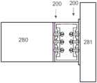
在其他情形中,在地板(或横梁)与剪力墙之间进行连接的结构设计中,连接是刚性的。在由地震引起的破坏运动的情况下,连接会引起其所连接的元件弯矩和扭转负荷,如图28中所见的。In other cases, in the structural design of the connection between the floor (or beam) and the shear wall, the connection is rigid. In the event of destructive motion caused by an earthquake, the connection induces bending moments and torsional loads on the elements it connects, as seen in Figure 28.
桥梁使用各种复杂性质的挠性连接,以助于垂直支撑桥面防止浮桥平台向下,但允许被调节到一定程度的平移和旋转相对运动。这对减弱地震负载并适应相关挠度是有必要的。同样对一定程度减弱因交通拥堵引起的垂直力。Bridges use flexible links of various complex natures to help vertically support the deck to prevent downward movement of the pontoon platform, but allow for relative translational and rotational movement that can be accommodated to a certain degree. This is necessary to attenuate seismic loads and accommodate associated deflections. It also weakens the vertical force caused by traffic jams to a certain extent.
因此,本发明的目的在于提供一种使用于结构的弹性滑动摩擦接头,用于减弱结构元件之间由外部负载引起的力传动,并且用于在施加外部负载之前使结构元件偏向其原来的处理。It is therefore an object of the present invention to provide an elastic sliding friction joint for use in structures for attenuating force transmission between structural elements caused by external loads and for biasing the structural elements towards their original handling before the external load is applied .
发明内容Contents of the invention
一种滑动连接件,所述滑动连接件连接第一部件和第二部件,以便允许所述部件之间的相对但对抗的移动,并且还完全返回此类移动;所述连接件包含或包括:A sliding joint connecting a first part and a second part so as to permit relative but opposing movement between said parts and also return such movement completely; said joint comprising or comprising:
第一元件,其可连接至所述第一部件,a first element connectable to said first part,
第二元件,其可连接至所述第二部件,a second element connectable to said second component,
第一元件和第二元件各自包含互相滑动的倾斜表面,以及the first member and the second member each include an inclined surface that slides against each other, and
至少一个弹性固定件,其使用互相滑动的倾斜表面来使元件保持在一起,以使得倾斜表面的相对运动可摩擦地对抗,并且其中倾斜表面倾斜于至少一个弹性固定件的作用线,以使得连接件至少部分返回第一元件和第二元件的倾斜表面的相对滑动移动。at least one elastic fastener which uses mutually sliding inclined surfaces to hold the elements together such that relative movement of the inclined surfaces is frictionally opposed, and wherein the inclined surfaces are inclined to the line of action of the at least one elastic fastener such that the connection Relative sliding movement of the member at least partially returning to the inclined surfaces of the first and second members.
优选地,为了至少部分返回第一元件和第二元件的倾斜表面的相对滑动移动,提供充足的倾斜表面与至少一个弹性固定件的作用线所成的倾斜角度,以使得在由至少一个弹性固定件保持两个元件下,互相滑动倾斜表面之间的摩擦阻力是可以克服的。Preferably, in order to at least partially return the relative sliding movement of the inclined surfaces of the first and second elements, there is provided a sufficient angle of inclination between the inclined surfaces and the line of action of the at least one elastic fixing so that when the at least one elastic fixing The frictional resistance between the inclined surfaces that slide against each other can be overcome when the two elements are held together.
优选地,其中所述第一元件和第二元件的倾斜表面的滑动移动的至少部分返回是至少在不存在外力的情况下产生的。Preferably, wherein the at least partial return of the sliding movement of the inclined surfaces of the first and second elements occurs at least in the absence of external forces.
优选地,第一元件和第二元件的倾斜表面的滑动移动的返回包含朝向平衡位置返回。Preferably, the return of the sliding movement of the inclined surfaces of the first and second elements comprises a return towards the equilibrium position.
优选地,第一元件和第二元件的倾斜表面的滑动移动的返回包含返回至平衡位置。Preferably, the return of the sliding movement of the inclined surfaces of the first and second elements comprises a return to the equilibrium position.
优选地,第一元件和第二元件的倾斜表面的滑动移动的至少部分返回包含完全返回所述滑动移动。Preferably, at least a partial return of the sliding movement of the inclined surfaces of the first and second elements comprises a complete return of said sliding movement.
优选地,第一元件和第二元件的滑动移动包含连接件远离定中心环境的移动,并且滑动移动的返回包含朝向定中心环境返回。Preferably, the sliding movement of the first and second elements comprises movement of the link away from the centering environment, and the return of the sliding movement comprises returning towards the centering environment.
优选地,为了使第一元件和第二元件的相对滑动移动在两个元件由至少一个弹性固定件保持下至少部分返回,90度角减去倾斜表面与至少一个弹性固定件的作用线之间的锐角的正切值是大于所述第一元件和第二元件的滑动倾斜表面之间的静摩擦系数。Preferably, in order for the relative sliding movement of the first element and the second element to return at least partially while the two elements are held by the at least one elastic fixing, the angle of 90 degrees minus the angle between the inclined surface and the line of action of the at least one elastic fixing The tangent of the acute angle is greater than the coefficient of static friction between the sliding inclined surfaces of the first member and the second member.
优选地,当所述滑动的倾斜表面之间的所述静摩擦系数在0.36与0.39之间时,所述90度的角减去所述倾斜表面与所述至少一个弹性固定件的作用线之间的锐角是在25度与30度之间的角度。Preferably, when the coefficient of static friction between the sliding inclined surfaces is between 0.36 and 0.39, the angle of 90 degrees minus the angle between the inclined surfaces and the line of action of the at least one elastic fixing member An acute angle of is an angle between 25 degrees and 30 degrees.
优选地,使所述第一元件和第二元件的所述倾斜表面的相对滑动移动在所述两个元件由所述至少一个弹性固定件保持下至少完全返回,90度角减去所述倾斜表面与所述至少一个弹性固定件的作用线之间的锐角的正弦,除以一和所述倾斜表面的角度的余弦的总和,大于所述相接倾斜表面之间的静摩擦系数。Preferably, relative sliding movement of said inclined surfaces of said first and second elements is at least fully returned with said two elements held by said at least one resilient mount, an angle of 90 degrees minus said inclination The sine of the acute angle between the surface and the line of action of the at least one elastic fastener, divided by the sum of one and the cosine of the angle of the inclined surface, is greater than the coefficient of static friction between the abutting inclined surfaces.
优选地,当所述滑动倾斜表面之间的静摩擦系数在0.36与0.39之间时,90度角减去所述倾斜表面与所述至少一个弹性固定件的作用线之间的锐角是在25度与45度之间的角。Preferably, when the coefficient of static friction between the sliding inclined surfaces is between 0.36 and 0.39, the angle of 90 degrees minus the acute angle between the line of action of the inclined surfaces and the at least one elastic fixing member is 25 degrees Angles between and 45 degrees.
优选地,90度角减去所述倾斜表面与所述至少一个弹性固定件的作用线之间的锐角是10度与90度之间的角。Preferably, the angle of 90 degrees minus the acute angle between said inclined surface and the line of action of said at least one elastic mount is an angle between 10 and 90 degrees.
优选地,第一元件呈现为波形的多个倾斜表面阵列,以及第二元件呈现为波形的多个互补倾斜表面阵列以与第一元件的阵列接合。Preferably, the first element exhibits an array of undulating multiple sloped surfaces and the second element exhibits an array of undulating multiple complementary sloped surfaces for engagement with the array of first elements.
优选地,第一元件呈现为多个上倾和下倾的倾斜表面阵列,以及第二元件呈现为多个上倾和下倾的倾斜表面阵列以与第一元件的阵列接合。Preferably, the first element exhibits a plurality of arrays of inclines and declines, and the second element exhibits an array of plurality of inclines and declines, for engagement with the array of first elements.
优选地,使得第一元件和第二元件的倾斜表面在彼此上方在倾斜表面的滑动移动的情况下滑上去。Preferably, the inclined surfaces of the first and second elements slide up over each other with sliding movement of the inclined surfaces.
优选地,其中第一元件和第二元件的相对滑动移动的返回速率是至少部分通过至少一个弹性固定件固持第一元件和第二元件的量值来确定的。Preferably, wherein the rate of return of the relative sliding movement of the first and second elements is determined at least in part by the amount by which the at least one resilient mount retains the first and second elements.
优选地,第一元件和第二元件通过至少一个弹性固定件固持在一起的量值的增加是与滑动移动的返回速度的增加有关的。Preferably, the increase in the magnitude by which the first and second elements are held together by the at least one elastic fastener is associated with an increase in the return speed of the sliding movement.
优选地,存在至少两个第二元件并且所述第二元件夹持至少一部分的第一元件。Preferably there are at least two second elements and said second elements clamp at least a part of the first element.
优选地,两个第二元件夹持至少一部分的第一元件。Preferably, the two second elements clamp at least a part of the first element.
优选地,弹性固定件穿过第一元件。Preferably, the elastic fastener passes through the first element.
优选地,弹性固定件从第二元件穿过所述第一元件。Preferably, the elastic mount passes from the second element through said first element.
优选地,弹性固定件穿过所述第二元件并穿过所述第一元件。Preferably, an elastic mount passes through said second element and through said first element.
优选地,所述弹性固定件的每一者包括紧固件,及至少一个偏向部件,所述偏向部件介于紧固件与第一及第二元件的组件之间,以施加偏向力,从而产生关联的弹性固定件的弹性保持。Preferably, each of said resilient mounts comprises a fastener, and at least one biasing member interposed between the fastener and the assembly of the first and second elements to apply a biasing force whereby An elastic hold of the associated elastic fixing is produced.
优选地,偏向部件是选自以下一个或多个的至少一个弹簧:Preferably, the biasing member is at least one spring selected from one or more of the following:
·膜片式弹簧垫圈,·Diaphragm spring washer,
·板弹簧,· Leaf springs,
·螺旋弹簧。· Coil spring.
优选地,其中测量第一部件和第二部件在移动期间的最大位移。Preferably, wherein the maximum displacement of the first part and the second part during movement is measured.
优选地,其中提供位移测量设备以测量以下至少一个:第一部件与第二部件之间的最大位移、第一元件相对于第二元件的位移、在平行于固定件的作用线的方向上第一元件相对于第二元件的位移、在垂直于所述固定件的作用线的方向上第一元件相对于第二元件的位移。Preferably, wherein a displacement measuring device is provided to measure at least one of: the maximum displacement between the first part and the second part, the displacement of the first element relative to the second element, the maximum displacement in a direction parallel to the line of action of the fixture. Displacement of an element relative to a second element, displacement of a first element relative to a second element in a direction perpendicular to the line of action of said fixture.
优选地,位移测量设备测量第一元件相对于第二元件的位移。Preferably, the displacement measuring device measures displacement of the first element relative to the second element.
优选地,位移测量设备测量在平行于固定件的作用线的方向上第一元件相对于第二元件的位移。Preferably, the displacement measuring device measures the displacement of the first element relative to the second element in a direction parallel to the line of action of the fixture.
优选地,位移测量设备测量在垂直于固定件的作用线的方向上第一元件相对于第二元件的位移。Preferably, the displacement measuring device measures the displacement of the first element relative to the second element in a direction perpendicular to the line of action of the fixture.
优选地,提供多个互相倾斜的表面,以界定波形的倾斜表面阵列,诸如三角波形、锯齿波形、正弦波形、截头三角波形。Preferably, a plurality of mutually inclined surfaces are provided to define an array of inclined surfaces of a waveform, such as triangular, sawtooth, sinusoidal, truncated triangular.
优选地,第一部件呈现为波形的多个倾斜表面阵列,以及第二部件呈现为波形的多个互补的倾斜表面阵列,以便与提及的第一阵列接合。Preferably, the first component exhibits an array of undulating multiple inclined surfaces and the second component exhibits an array of undulating multiple complementary inclined surfaces so as to engage the first array in question.
因此在本发明另一方面,可被大体上称为一种滑动连接件,所述滑动连接件连接第一部件和第二部件,以便允许部件之间的相对但对抗的外力引起的移动,且也至少部分地返回任何移动;所述连接件包含或包括:Thus in another aspect of the invention may generally be referred to as a sliding connection which connects a first part and a second part so as to allow relative but opposing force-induced movement between the parts, and Any movement is also returned at least in part; said connection comprises or includes:
a)第一元件,所述第一元件可连接至所述第一部件,a) a first element connectable to said first part,
b)第二元件,b) the second element,
c)至少一个第三元件,所述第三元件搭接在第一元件及第二元件的至少一者的至少一部分的上方及/或下方,第二元件和至少一个第三元件中的至少一个可连接至第二部件,c) at least one third element that overlaps over and/or under at least a portion of at least one of the first element and the second element, at least one of the second element and the at least one third element can be connected to a second part,
d)至少一个弹性固定件,其用以使第一元件和第三元件保持相接,以及d) at least one elastic fastener for holding the first element and the third element in contact, and
e)至少一个弹性固定件,用以使第二及第三元件保持相接;e) at least one elastic fastener to keep the second and third elements in contact;
其中第一元件和第三元件各自相接的相互关系是互相倾斜的表面,从而The mutual relationship in which the first member and the third member respectively meet are mutually inclined surfaces, whereby
允许在外力下第一元件和第三元件相对于彼此以及第二元件和第三元件相对于彼此的第一方向上的相对滑动,所述相对滑动是倾斜于关联的弹性固定件的弹性保持方向。Relative sliding in a first direction of the first and third elements relative to each other and the second and third elements relative to each other is permitted under external force, said relative sliding being oblique to the elastic retaining direction of the associated elastic fixing .
固定件,使得在停止外力之后,使得元件在与第一方向相反的方向上返回。The fixing member is such that after stopping the external force, the element is returned in a direction opposite to the first direction.
优选地,在由至少一个弹性固定件保持两个元件下,提供与第一方向相反方向上的返回,其中90度角减去倾斜表面与至少一个弹性固定件的作用线之间的锐角的正切值是大于所述第一元件和第二元件的互相倾斜表面之间的静摩擦系数。Preferably, with the two elements held by the at least one elastic fixing, a return is provided in a direction opposite to the first direction, wherein the angle of 90 degrees minus the tangent of the acute angle between the inclined surface and the line of action of the at least one elastic fixing The value is greater than the coefficient of static friction between the mutually inclined surfaces of the first element and the second element.
优选地,其中当滑动倾斜表面之间的静摩擦系数在0.36与0.39之间时,90度角减去倾斜表面与至少一个弹性固定件的作用线之间的锐角的角是在25度与30度之间。Preferably, wherein when the coefficient of static friction between the sliding inclined surfaces is between 0.36 and 0.39, the angle of 90 degrees minus the acute angle between the inclined surfaces and the line of action of the at least one elastic fixing member is between 25 degrees and 30 degrees between.
优选地,其中提供两个第三元件,一个第三元件搭接在第一元件和所述第二元件的至少一个的部分的上方,并且一个搭接在第一元件和第二元件的至少一个的相对应部分的下方,各个上方搭接或下方搭接部分具有互相倾斜表面的相接的相互关系。Preferably, two third elements are provided, one overlying part of at least one of the first element and said second element, and one overlapping at least one of the first element and said second element Each of the overlapping or underlapping portions has a butting relationship of mutually sloping surfaces below the corresponding portion of each.
优选地,在由至少一个弹性固定件保持两个元件下,提供与第一方向相反方向上的返回,其中90度减去所述倾斜表面与至少一个弹性固定件的作用线之间的锐角的正弦,除以一和倾斜表面的角度的余弦的总和,是大于所述互相倾斜表面之间的静摩擦系数。Preferably, with the two elements held by at least one elastic fixing, a return in a direction opposite to the first direction is provided, wherein 90 degrees minus the acute angle between the inclined surface and the line of action of the at least one elastic fixing The sum of the sine, divided by one and the cosine of the angle of the inclined surfaces, is greater than the coefficient of static friction between the mutually inclined surfaces.
优选地,其中当滑动倾斜表面之间的静摩擦系数在0.36与0.39之间时,90度角减去倾斜表面与至少一个弹性固定件的作用线之间的锐角的角是在25度与45度之间。Preferably, wherein when the coefficient of static friction between the sliding inclined surfaces is between 0.36 and 0.39, the angle of 90 degrees minus the acute angle between the inclined surfaces and the line of action of the at least one elastic fixing member is between 25 degrees and 45 degrees between.
优选地,第二元件连接至第二部件。Preferably, the second element is connected to the second component.
优选地,第三元件连接至第二部件。Preferably, the third element is connected to the second part.
优选地,当第一元件和第三元件相对滑动时,连接件不会使第一部件和第二部件在弹性保持的方向上相对于彼此位移。Preferably, the link does not displace the first part and the second part relative to each other in the elastically held direction when the first element and the third element slide relative to each other.
优选地,当第二元件和第三元件相对滑动时,连接件不会使第一部件和第二部件在弹性保持的方向上相对于彼此位移。Preferably, the link does not displace the first part and the second part relative to each other in the elastically held direction when the second element and the third element slide relative to each other.
优选地,当第二元件和第三元件相对滑动时,连接件不会使第一部件和第二部件在弹性保持的方向上相对于彼此位移。Preferably, the link does not displace the first part and the second part relative to each other in the elastically held direction when the second element and the third element slide relative to each other.
优选地,存在两个第三元件,至少一个第三元件可连接至第二部件。Preferably, there are two third elements, at least one third element being connectable to the second part.
优选地,第二元件及第三元件存在着相接的相互关系且其为互相倾斜的表面;且其中所述互相倾斜的表面允许第二及第三元件在倾斜于关联的弹性固定件的弹性保持方向上的相对滑动。Preferably, the second element and the third element are in abutting mutual relationship and are mutually inclined surfaces; and wherein said mutually inclined surfaces allow the second and third elements to be inclined against the elasticity of the associated elastic fixing member. Keep the relative slide in direction.
优选地,不存在第二元件且第三元件连接至至少一个第二部件,且优选地连接至数个第二部件。Preferably, there is no second element and the third element is connected to at least one second component, and preferably to several second components.
优选地,至少一个所述第三元件能够相对于其所结合的第一及/或第二元件横向位移。Preferably, at least one of said third elements is laterally displaceable relative to the first and/or second element to which it is incorporated.
优选地,所述弹性固定件获取具有至少一个第三元件的第一元件。Preferably, the elastic mount acquires a first element with at least one third element.
优选地,所述弹性固定件各自包含单头且优选地双头的紧固件及至少一个偏向部件,所述偏向部件介于紧固件与第一元件及第三元件且优选地第二元件的组件之间,在单头且优选地双头之间,施加偏向力以产生至少一个关联的弹性固定件的弹性保持。Preferably, said elastic fasteners each comprise a single-ended and preferably double-ended fastener and at least one biasing member interposed between the fastener and the first element and the third element, preferably the second element Between the components, between the single head and preferably the double head, a biasing force is applied to produce elastic retention of at least one associated elastic fixing.
优选地,所述单头且优选地双头的紧固件是带螺纹的。Preferably, said single-ended and preferably double-ended fasteners are threaded.
优选地,所述双头的带螺纹的紧固件包含螺栓与螺母。Preferably, said double-ended threaded fastener comprises a bolt and a nut.
优选地,至少一个偏向部件是选自以下一个或多个的至少一个弹簧:板弹簧、螺旋弹簧、膜片式弹簧垫圈。Preferably, the at least one biasing member is at least one spring selected from one or more of the following: leaf springs, helical springs, diaphragm spring washers.
优选地,每一个弹性固定件具有专用的偏向部件。Preferably, each elastic mount has a dedicated biasing member.
优选地,每一个弹性固定件依赖于一个偏向部件。Preferably, each resilient mount relies on a biasing member.
优选地,针对每一个弹性固定件提供多个偏向部件。Preferably, a plurality of biasing members are provided for each elastic mount.
优选地,每一个偏向部件作用于带螺纹的紧固件的头部与相邻的第三元件之间。Preferably, each biasing member acts between the head of the threaded fastener and an adjacent third element.
优选地,偏向部件设在每个头部与其相邻的第三元件之间。Preferably, a biasing member is provided between each head and its adjacent third element.
优选地,如前面提及的偏向部件可为多个偏向部件的一个组件。Preferably, the deflection member as mentioned before may be an assembly of a plurality of deflection members.
优选地,所述两个第三元件一起用作具有弹性固定件的弹性可扩展的夹具,以夹持所述第一元件的至少部分。Preferably, said two third elements together act as a resiliently expandable clamp with resilient fixings to clamp at least part of said first element.
优选地,存在两个所述第三元件,所述两个第三元件用作具有所述弹性固定件的弹性可扩展的夹具,以夹持所述第一元件及所述第二元件的至少部分。Preferably, there are two of said third elements, said two third elements acting as elastically expandable clamps with said elastic mounts to hold at least one of said first element and said second element part.
优选地,所述第一及第三元件被调适并设置为以线性平移的方式相对于彼此移动。Preferably, said first and third elements are adapted and arranged to move relative to each other in linear translation.
优选地,每一个第三元件是线性延长部件,所述线性延长部件在第三元件与所述第一元件之间的相对移动方向上延伸。Preferably, each third element is a linear extension extending in the direction of relative movement between the third element and said first element.
优选地,每一个第三元件是线性延长部件,所述线性延长部件在所述第三元件与所述第一元件及所述第二元件之间的相对移动方向上延伸。Preferably, each third element is a linearly elongated member extending in the direction of relative movement between the third element and the first and second elements.
优选地,以下的至少一者及优选地两者:(a)提供有所述第三元件的至少一者及优选地两者,及(b)所述第一元件针对所述滑动提供向上倾斜及向下倾斜的斜面阵列并使所述夹具膨胀。Preferably at least one and preferably both of: (a) at least one and preferably both of said third elements are provided, and (b) said first element provides an upward slope for said sliding and an array of ramps that slope downward and expand the clamp.
优选地,所述第一元件呈现为波形的多个倾斜表面阵列,以及所述第二元件呈现为波形的多个互补的倾斜表面阵列,以便与所述第一元件的阵列接合。Preferably, said first element exhibits an array of undulating multiple sloped surfaces and said second element exhibits an array of undulating multiple complementary sloped surfaces for engagement with said array of first elements.
优选地,第一元件呈现为多个上倾斜和下倾斜的倾斜表面阵列,以及第二元件呈现为多个上倾斜和下倾斜的倾斜表面阵列,以便与所述第一元件的阵列接合。Preferably, the first element exhibits an array of upwardly and downwardly inclined sloped surfaces and the second element exhibits an array of upwardly and downwardly sloped sloped surfaces for engagement with said array of first elements.
优选地,使得第一元件和第二元件的倾斜表面在彼此上方在所述倾斜表面的滑动移动的情况下滑上去。Preferably, the inclined surfaces of the first and second elements slide up over each other with sliding movement of said inclined surfaces.
优选地,所述阵列在平行于至少一个第三元件相对于第一元件的移动的方向上延伸。Preferably, the array extends in a direction parallel to the movement of the at least one third element relative to the first element.
优选地,所述结构是建筑结构。Preferably, the structure is an architectural structure.
优选地,所述第一部件选自以下中的一者:横梁、柱形物、底板支柱与基座。Preferably, the first component is selected from one of the following: beams, columns, floor pillars and bases.
优选地,在施加力以致第三元件相对于第一元件并对着弹性固定件的偏向而移动之后,所述倾斜表面及弹性固定件被调适并设置为允许在相邻元件的滑动之后滑上去,所述弹性固定件又会使滑动元件朝向平衡位置偏向。Preferably, said inclined surface and resilient mount are adapted and arranged to allow sliding up after sliding of an adjacent element upon application of a force such that the third element moves relative to the first element and against the deflection of the resilient mount , the elastic fixing member in turn biases the sliding element towards the equilibrium position.
优选地,以下的至少一者及优选地两者:(a)提供有所述第三元件的至少一者及优选地两者,及(b)所述第一元件及所述第二元件针对所述滑动提供向上倾斜及向下倾斜的斜面阵列并使所述夹具膨胀。Preferably, at least one and preferably both of: (a) at least one and preferably both of said third elements are provided, and (b) said first and said second elements are directed against The sliding provides an array of upward and downward slopes and expands the clamp.
优选地,所述阵列在平行于第三元件相对于第一及第二元件的移动的方向上延伸。Preferably, the array extends in a direction parallel to the movement of the third element relative to the first and second elements.
优选地,第一部件和第二部件是结构的结构部件。Preferably, the first part and the second part are structural parts of the structure.
优选地,所述结构是建筑结构。Preferably, the structure is an architectural structure.
优选地,第一部件选自以下中的一者:横梁、柱形物、底板支柱与基座。Preferably, the first component is selected from one of the following: beams, columns, floor struts and bases.
优选地,第二部件选自以下中的一者:横梁、柱形物、底板支柱与基座。Preferably, the second component is selected from one of the following: beams, columns, floor struts and bases.
优选地,在施加力以致第三元件相对于第一及第二元件并对着弹性固定件的偏向而移动之后,所述倾斜表面及弹性固定件被调适并设置为允许在相邻元件的滑动之后滑上去,所述弹性固定件又会使滑动元件朝向平衡位置偏向。Preferably, said inclined surface and resilient mount are adapted and arranged to allow sliding movement of the adjacent element upon application of a force such that the third element is displaced relative to the first and second elements and against the deflection of the resilient mount Sliding up thereafter, the elastic mount again biases the sliding element towards the equilibrium position.
优选地,第一元件及第三元件被调适并设置为围绕旋转轴彼此相对旋转,所述第一元件及第三元件的每一个包括互相结合的表面,以允许在大体上径向延伸至旋转轴的表面之间发生倾斜的滑动。Preferably, the first and third elements are adapted and arranged to rotate relative to each other about an axis of rotation, each of said first and third elements comprising mutually engaging surfaces to allow a substantially radial extension to rotate Inclined sliding occurs between the surfaces of the shaft.
优选地,表面在以完全围绕旋转轴旋转的方式于彼此上方倾斜上升及倾斜下降时移动。Preferably the surfaces move while ramping up and ramping down over each other in full rotation about the axis of rotation.
优选地,当表面以倾斜方式滑动时,第一及第三元件在平行于所述旋转轴的方向上彼此相对移动,又围绕其旋转。Preferably, the first and third elements move relative to each other in a direction parallel to said axis of rotation and rotate about it when the surface slides in an oblique manner.
优选地,在提供两个第三元件的情况下,由于连接表面没有倾斜而是为平面的,一个第三元件在相对旋转之后可能不会横向于第一元件移动,所述旋转轴垂直于所述平面。Preferably, in the case where two third elements are provided, one third element may not move laterally to the first element after relative rotation, the axis of rotation being perpendicular to the Description plane.
优选地,在旋转形式中,倾斜表面具有法线,所述法线不会:(a)平行于旋转轴,及(b)垂直于旋转轴。Preferably, in the rotated form, the inclined surface has a normal that is not: (a) parallel to the axis of rotation, and (b) perpendicular to the axis of rotation.
优选地,在旋转形式中,倾斜表面在距旋转轴的任何给定的径向距离处具有法线,在以平行于旋转轴的方向查看所述法线时,所述法线相切于径向距离处的假想的圆。Preferably, in the rotated form, the inclined surface has a normal at any given radial distance from the axis of rotation that is tangent to the radial axis when viewed in a direction parallel to the axis of rotation. An imaginary circle at the distance.
优选地,第一元件及第二元件包括互相倾斜的表面,当使得所述第一及第三元件以任何二维平移方式位移时,所述互相倾斜的表面可在第一及第三元件之间产生横向移动。Preferably, the first and second elements comprise mutually inclined surfaces which can be positioned between the first and third elements when said first and third elements are displaced in any two-dimensional translation. Lateral movement occurs.
优选地,第一元件和第三元件被调适并设置为以线性平移的方式相对于彼此移动。Preferably, the first element and the third element are adapted and arranged to move relative to each other in linear translation.
优选地,第一部件和第二部件是结构的结构部件。Preferably, the first part and the second part are structural parts of the structure.
优选地,结构是建筑结构。Preferably, the structure is an architectural structure.
优选地,第一部件选自以下中的一者:横梁、柱形物、底板支柱与基座。Preferably, the first component is selected from one of the following: beams, columns, floor struts and bases.
优选地,第二部件选自以下中的一者:横梁、柱形物、底板支柱与基座。Preferably, the second component is selected from one of the following: beams, columns, floor struts and bases.
因此,在本发明的进一方面上,可被大体上称为一种结构连接件,所述结构连接件在两个结构部件之间提供阻尼和位置恢复功能,所述两个结构部件可经受外力,使得两个结构部件相对移动,所述连接件包含:Thus, in a further aspect of the invention, what may generally be referred to as a structural connection provides a damping and position restoration function between two structural components that can withstand An external force causes two structural components to move relative to each other, the connection comprising:
第一摩擦板,所述第一摩擦板与第二摩擦板并列,在偏向力下固持在一起,使所述第一摩擦板和第二摩擦板的摩擦表面连接,从而能够以与偏向力的方向成角度的方向上在彼此上方相对于彼此滑动,并且第一摩擦板和第二摩擦板的连接表面之间的静摩擦系数使得,当所述两个结构部件经受所述运动而将外力施加至所述第一摩擦板和所述第二摩擦板时,偏向力使所述第一摩擦板和第二摩擦板的连接表面在与所述提及的第一方向相反的方向上滑动,其中具有足够的量值,以便克服板的连接表面之间的静摩擦力。The first friction plate, the first friction plate and the second friction plate are juxtaposed, and are held together under the biasing force, so that the friction surfaces of the first friction plate and the second friction plate are connected, so as to be able to match the biasing force Sliding relative to each other over each other in an angled direction, and the static coefficient of friction between the connecting surfaces of the first friction plate and the second friction plate is such that when the two structural components undergo the movement an external force is applied to When the first friction plate and the second friction plate are engaged, the biasing force causes the connecting surface of the first friction plate and the second friction plate to slide in a direction opposite to the mentioned first direction, wherein there is Sufficient magnitude so as to overcome the static friction between the connecting surfaces of the plates.
优选地,第一摩擦板和第二摩擦板的连接表面各自包含互相滑动的倾斜表面,板在彼此上方并相对于彼此的滑动角度是通过所述倾斜表面的倾斜角确定。Preferably, the connection surfaces of the first friction plate and the second friction plate each comprise inclined surfaces sliding against each other, and the sliding angle of the plates over each other and relative to each other is determined by the angle of inclination of said inclined surfaces.
优选地,互相滑动的倾斜表面各自包含多个向上倾斜和向下倾斜的斜面。Preferably, the mutually sliding inclined surfaces each comprise a plurality of upwardly inclined and downwardly inclined slopes.
优选地,倾斜表面是锯齿波形轮廓。Preferably, the inclined surface is a sawtooth wave profile.
优选地,倾斜表面倾斜于偏向力的作用线。Preferably, the inclined surface is inclined to the line of action of the deflecting force.
优选地,与第一方向相反的方向上的滑动包含朝向平衡位置的返回。Preferably, sliding in a direction opposite to the first direction involves a return towards the equilibrium position.
优选地,与第一方向相反的方向上的滑动包含返回至平衡位置。Preferably, sliding in a direction opposite to the first direction includes returning to the equilibrium position.
优选地,与第一方向相反的方向上的滑动包含第一方向上所述滑动移动的完全返回。Preferably, sliding in a direction opposite to the first direction involves a full return of said sliding movement in the first direction.
优选地,第一元件与第一结构数目关联并且第二元件与第二结构数目关联。Preferably, the first element is associated with a first structure number and the second element is associated with a second structure number.
优选地,滑动连接件进一步包含:至少一个第三摩擦板,其通过偏向力搭接在上方和/或下方并通过其固持,第一摩擦板和第二摩擦板的至少一个的至少一部分,并且其中在至少一个第三摩擦板与第一摩擦板和所述第二摩擦板的至少一个之间进一步提供连接摩擦表面。Preferably, the sliding connection further comprises: at least one third friction plate overlapping above and/or below and retained by biasing force, at least a portion of at least one of the first friction plate and the second friction plate, and Wherein a connecting friction surface is further provided between at least one third friction plate and at least one of the first friction plate and said second friction plate.
优选地,第一元件与第一结构部件关联以及第三元件与第二结构部件关联。Preferably, the first element is associated with the first structural component and the third element is associated with the second structural component.
优选地,在由所述至少一个弹性固定件固持所述两个元件的情况下,在没有外力时提供与所述第一方向相反方向上的滑动,其中90度角减去所述倾斜表面与所述至少一个弹性固定件的作用线之间的锐角的正切值是大于所述第一元件和第二元件的所述滑动倾斜表面之间的静摩擦系数。Preferably, with said two elements held by said at least one elastic mount, sliding in a direction opposite to said first direction is provided in the absence of external force, wherein an angle of 90 degrees minus said inclined surface and A tangent of an acute angle between lines of action of the at least one elastic fixing is greater than a coefficient of static friction between the sliding inclined surfaces of the first element and the second element.
优选地,当所述滑动的倾斜表面之间的所述静摩擦系数在0.36与0.39之间时,所述90度的角减去所述倾斜表面与所述至少一个弹性固定件的作用线之间的锐角是在25度与30度之间的角度。Preferably, when the coefficient of static friction between the sliding inclined surfaces is between 0.36 and 0.39, the angle of 90 degrees minus the angle between the inclined surfaces and the line of action of the at least one elastic fixing member An acute angle of is an angle between 25 degrees and 30 degrees.
优选地,设有两个第三元件,一个是上方搭接的且另一个是下方搭接的。Preferably, there are two third elements, one overlapping above and one overlapping below.
优选地,在由所述至少一个弹性固定件保持所述两个元件下,提供与第一方向相反方向上的连接件返回,其中90度减去所述倾斜表面与所述至少一个弹性固定件的作用线之间的锐角的正弦,除以一和所述倾斜表面的角度的余弦的总和,是大于所述互相倾斜表面之间的静摩擦系数。Preferably, with said two elements being held by said at least one elastic fixing, a connection return is provided in a direction opposite to the first direction, wherein 90 degrees minus said inclined surface and said at least one elastic fixing The sine of the acute angle between the lines of action, divided by a sum of the cosines of the angles of said inclined surfaces, is greater than the coefficient of static friction between said mutually inclined surfaces.
优选地,当所述滑动的倾斜表面之间的所述静摩擦系数在0.36与0.39之间时,所述90度的角减去所述倾斜表面与所述至少一个弹性固定件的作用线之间的锐角是在25度与45度之间的角度。Preferably, when the coefficient of static friction between the sliding inclined surfaces is between 0.36 and 0.39, the angle of 90 degrees minus the angle between the inclined surfaces and the line of action of the at least one elastic fixing member An acute angle of is an angle between 25 degrees and 45 degrees.
优选地,提供限制以限制所述第一摩擦板和所述第二摩擦板的所述连接表面的滑动,所述限制防止滑动超出向上倾斜或向下倾斜的斜面长度。Preferably, a restriction is provided to restrict sliding of said connection surfaces of said first and second friction plates, said restriction preventing sliding beyond the length of an upwardly inclined or downwardly inclined slope.
优选地,至少一个弹性固定件提供所述偏向力,所述至少一个弹性固定件各自包含紧固件,以及至少一个偏向部件,所述至少一个偏向部件置于所述紧固件与所述摩擦板的组件之间,并且其中所述至少一个弹性固定件提供所述限制。Preferably, at least one elastic fixing member provides said biasing force, said at least one elastic fixing member each includes a fastener, and at least one biasing member, said at least one biasing member is placed between said fastener and said friction between assemblies of panels, and wherein said at least one resilient fastener provides said confinement.
优选地,偏向力是由至少一个弹簧提供的。Preferably, the biasing force is provided by at least one spring.
优选地,偏向力是由弹簧或弹簧组件提供的。Preferably, the biasing force is provided by a spring or spring assembly.
优选地,当由所述两个结构部件施加的外力停止时,所述偏向力足以使所述第一摩擦板和第二摩擦板的所述连接表面在与所述提及的第一方向相反的方向上滑动。Preferably, said biasing force is sufficient to cause said connecting surfaces of said first and second friction plates to be in a direction opposite to said first mentioned direction when the external force exerted by said two structural members ceases. Swipe in the direction of the
优选地,当所述第一摩擦板和第二摩擦板的所述连接表面在所述提及的第一方向上彼此相对滑动时,所述摩擦板对着所述偏向力横向地分离,且在垂直于所述偏向力的方向上纵向地位移。Preferably, said friction plates separate laterally against said biasing force when said connecting surfaces of said first and second friction plates slide relative to each other in said mentioned first direction, and longitudinally displaced in a direction perpendicular to said biasing force.
优选地,当所述第一摩擦板和第二摩擦板的所述连接表面在与所述提及的第一方向相反的方向上彼此相对滑动时,所述摩擦板使用所述偏向力横向地加固,且在垂直于所述偏向力的方向上纵向地位移。Preferably, said friction plates laterally use said biasing force when said connecting surfaces of said first and second friction plates slide relative to each other in a direction opposite to said mentioned first direction stiffened, and longitudinally displaced in a direction perpendicular to said biasing force.
优选地,所述摩擦板以线性平移方式相对于彼此移动。Preferably, said friction plates move relative to each other in linear translation.
优选地,当所述第一摩擦板和第二摩擦板的所述连接表面在所述提及的第一方向上彼此相对滑动时,可以使所述摩擦板在一个方向上围绕旋转轴旋转地位移且在与所述偏向力的所述方向平行的方向上分离。Preferably, when the connecting surfaces of the first friction plate and the second friction plate slide relative to each other in the mentioned first direction, the friction plates can be rotated in one direction about a rotation axis. and separate in a direction parallel to said direction of said biasing force.
优选地,当所述第一摩擦板和第二摩擦板的所述连接表面在与所述提及的第一方向的相反的所述方向上彼此相对滑动时,可以使所述摩擦板在一个方向上围绕旋转轴旋转地位移且在与所述偏向力的所述方向平行的方向上加固。Preferably, when said connecting surfaces of said first and second friction plates slide relative to each other in said direction opposite to said mentioned first direction, said friction plates may be caused to move in a direction is rotationally displaced about an axis of rotation and is stiffened in a direction parallel to said direction of said biasing force.
优选地,当所述第一摩擦板和第二摩擦板的所述连接表面彼此相对滑动时,可以使所述摩擦板以在平面全方向的方式中彼此相对滑动且在与所述偏向力的所述方向相反的所述平面的法线平行的方向上分离。Preferably, when the connecting surfaces of the first friction plate and the second friction plate slide relative to each other, the friction plates can be caused to slide relative to each other in a planar omnidirectional manner and in relation to the biasing force The opposite direction is separated in a direction parallel to the normal of the plane.
优选地,测量/记录所述两个摩擦板之间的至少最大位移。Preferably, at least a maximum displacement between said two friction plates is measured/recorded.
优选地,测量/记录在与所述偏向力平行的方向上的所述两个摩擦板之间的所述位移。Preferably, said displacement between said two friction plates in a direction parallel to said biasing force is measured/recorded.
优选地,测量/记录在与所述偏向力垂直的方向上的所述两个摩擦板之间的所述位移。Preferably, said displacement between said two friction plates in a direction perpendicular to said biasing force is measured/recorded.
优选地,将位移测量设备应用于所述结构连接件,以便于测量/记录。Preferably, displacement measurement equipment is applied to the structural connection to facilitate measurement/recording.
因此,在本发明的另一方面中,可被大体上称为一种结构连接件,所述结构连接件在两个结构部件之间提供阻尼及位置恢复功能,所述两个结构部件可经受使得所述两个结构部件相对移动的运动,所述连接件包含:Thus, in another aspect of the invention, what may generally be referred to as a structural connection provides damping and position restoration between two structural components that can withstand motion that causes relative movement of the two structural members, the connection comprising:
作为第一组,第一摩擦板,所述第一摩擦板与第二摩擦板并列,在偏向力下固持在一起,当所述两个结构部件经受所述运动而将外力施加至所述第一摩擦板和所述第二摩擦板时,使第一摩擦板及第二摩擦板的摩擦表面连接,从而能够在与偏向力的方向成小于90度并大于10度的角的方向上在彼此上方相对于彼此滑动,偏向力使第一摩擦板及第二摩擦板的连接表面在与所述提及的第一方向相反的方向上滑动,作为第二组,第三摩擦板,所述第三摩擦板与第四摩擦板并列,在第二偏向力下固持在一起,当所述两个结构部件经受所述运动而将外力施加至所述第三摩擦板和所述第四摩擦板时,使第三摩擦板和第四摩擦板的摩擦表面连接,从而能够在与所述第二偏向力的方向成小于90度并大于10度的角的方向上在彼此上方相对于彼此滑动,第二偏向力使所述第三摩擦板和第四摩擦板的连接表面在与所述提及的第一方向相反的方向上滑动,As a first set, first friction plates, said first friction plate juxtaposed with a second friction plate, held together under a biasing force, when said two structural members undergo said movement an external force is applied to said first friction plate When a friction plate and the second friction plate are used, the friction surfaces of the first friction plate and the second friction plate are connected so as to be able to move against each other in the direction of an angle of less than 90 degrees and greater than 10 degrees with the direction of the biasing force sliding relative to each other above, the biasing force causes the connecting surfaces of the first friction plate and the second friction plate to slide in a direction opposite to the mentioned first direction, as the second set, the third friction plate, the first A third friction plate is juxtaposed with a fourth friction plate, held together under a second biasing force, when said two structural members undergo said motion applying an external force to said third friction plate and said fourth friction plate , connecting the friction surfaces of the third friction plate and the fourth friction plate so as to be able to slide relative to each other over each other in a direction forming an angle of less than 90 degrees and greater than 10 degrees with the direction of the second biasing force, the first two biasing forces cause the connecting surfaces of said third and fourth friction plates to slide in a direction opposite to said first direction,
其中以下至少一者at least one of the following
(a)第一及第二板的滑动方向角度不同于第三及第四板的滑动方向角度(a) The sliding direction angles of the first and second plates are different from the sliding direction angles of the third and fourth plates
(b)提及的第一偏向力不同于第二偏向力,以及(b) the first biasing force referred to is different from the second biasing force, and
(c)在结合所述第三及第四摩擦板以在彼此上方滑动之前,需要达到所述两个结构部件的相关移动的临界值。(c) A threshold value of relative movement of the two structural components needs to be reached before engaging the third and fourth friction plates to slide over each other.
因此,在本发明的另一方面,可被大体上称为一种连接件,所述连接件可以通过以下方式将第一建筑部件及至少一个其他建筑部件连接在一起:在外部引起的振动事件期间允许第一部件相对于所述第二部件弹性位移,所述连接件包含组件,所述组件包含第一元件,所述第一元件与所述第一建筑部件及夹紧组件一起移动,以至少部分夹持所述第一元件,所述夹紧组件直接或间接地被连接至所述至少一个其他建筑部件并相对于所述第一建筑部件移动,Accordingly, in another aspect of the present invention may generally be referred to as a joint that can join together a first building element and at least one other building element by means of an externally induced vibration event during which elastic displacement of the first part relative to the second part is allowed, the connection comprises an assembly comprising a first element which moves together with the first building part and the clamping assembly to at least partially clamping said first element, said clamping assembly being directly or indirectly connected to said at least one other construction component and movable relative to said first construction component,
夹紧组件在横向于第一建筑部件与至少一个其他建筑部件之间的相对移动的方向的方向上弹性可扩展,又通过偏向构件来偏向以使具有互相滑动表面的夹紧组件及第一元件保持相接,所述偏向构件的作用线倾斜于保持相接的滑动表面。The clamping assembly is elastically expandable in a direction transverse to the direction of relative movement between the first building component and at least one other building component, and is biased by a biasing member such that the clamping assembly and the first element have mutual sliding surfaces Keeping in touch, the line of action of said deflection members is inclined to the keeping in touch sliding surfaces.
优选地,夹紧组件包括至少一个弹性螺栓固定件,以使具有互相滑动的表面的两个元件相接。Preferably, the clamping assembly comprises at least one resilient bolt fixture to abut two elements having mutually sliding surfaces.
优选地,偏向构件是弹簧。Preferably, the biasing member is a spring.
优选地,弹簧是压缩弹簧或拉伸弹簧。Preferably, the spring is a compression spring or a tension spring.
优选地,弹簧可包括以下至少一者:板弹簧、螺旋弹簧、膜片式弹簧垫圈。Preferably, the spring may include at least one of the following: leaf spring, coil spring, diaphragm spring washer.
优选地,夹紧组件在横向方向和第一建筑部件与第二建筑部件之间的相对位移方向上相对于所述第二建筑部件移动。Preferably, the clamping assembly moves relative to the second building element in the transverse direction and in the direction of relative displacement between the first building element and the second building element.
优选地,所述位移是线性位移。Preferably, said displacement is a linear displacement.
优选地,位移是旋转的位移。Preferably, the displacement is a rotational displacement.
优选地,留供横向膨胀之用的所述位移是平面位移。Preferably, said displacement reserved for lateral expansion is a planar displacement.
因此,在本发明的另一方面,可被大体上称为一种滑动连接件,所述滑动连接件在结构部件之间提供滑动连接,所述连接件,不管是包括或不包括待结合的任何匹配件,还是包括或不包括待结合的任何部件,所述结构部件,其具有界接表面的至少两个元件,被调适以彼此相对滑动并通过至少一个固定件被保持为所述界接的关系,所述至少一个固定件在其运动的路线上具有弹性,且所述运动的路线倾斜于所述连接表面。Thus, in another aspect of the invention, it may generally be referred to as a sliding joint providing a sliding connection between structural components, said joint, whether including or not including the Any mating part, also including or excluding any part to be joined, said structural part, at least two elements having an interface surface, adapted to slide relative to each other and held at said interface by at least one fixing The at least one fixing member has elasticity on its moving path, and the moving path is inclined to the connecting surface.
优选地,仅存在两个元件,且每一个被调适为直接或间接地连接至各自所述的结构部件。Preferably there are only two elements and each is adapted to be connected directly or indirectly to the respective described structural part.
根据另一方面,存在至少三个元件,是According to another aspect, there are at least three elements, being
第一元件,所述第一元件可连接至所述第一部件,a first element connectable to the first part,
第二元件,所述第二元件可连接至所述第二部件,a second element connectable to the second part,
至少第三元件,所述第三元件位于所述第一元件的搭接部分以及所述第二元件的部分的上方及/或下方,at least a third element located above and/or below an overlapping portion of said first element and a portion of said second element,
至少一个弹性固定件,所述弹性固定件用以使第一元件及至少第三元件保持处于连接表面的关系,以及at least one resilient mount for maintaining the first element and the at least third element in relation to the connecting surface, and
至少一个弹性固定件,所述弹性固定件用以使第二元件及至少第三元件保持处于连接表面的关系。At least one elastic fixing member is used to keep the second element and at least the third element in the relationship of the connection surface.
根据另一方面,每一个表面与表面的相互关系是互相倾斜表面;According to another aspect, each surface-to-surface relationship is a mutually inclined surface;
并且其中所述互相倾斜表面允许在倾斜于关联元件的关联固定件的弹性保持的方向上进行相对滑动。And wherein said mutually inclined surfaces allow relative sliding in a direction oblique to the elastic retention of the associated fixing of the associated element.
优选地,每一个表面与表面的相互关系是每一个区域倾斜于所述作用线的多个表面区域的。Preferably, each surface-to-surface relationship is a plurality of surface areas per area oblique to said line of action.
优选地,每一个表面与表面的相互关系是互相倾斜的表面的,所述表面是三角波形的。Preferably, each surface-to-surface relationship is that of mutually inclined surfaces, said surfaces being triangular-shaped.
优选地,每一个表面与表面的相互关系是互相倾斜的表面的,所述表面是锯齿波形的。Preferably, each surface-to-surface relationship is that of mutually inclined surfaces, said surfaces being sawtooth-shaped.
优选地,每一个表面与表面的相互关系是互相倾斜的表面的,所述表面是正弦波形的。Preferably, each surface-to-surface relationship is that of mutually inclined surfaces, said surfaces being sinusoidal.
优选地,每一个固定件是或者包括螺栓与螺母。Preferably, each fixing member is or includes a bolt and a nut.
优选地,每一个螺栓与螺母包括至少一个弹性垫圈或弹簧。Preferably, each bolt and nut comprises at least one elastic washer or spring.
因此,在本发明的另一方面中,可被大体上称为一种建筑结构,滑动连接件位于所述结构的部件之间,以允许部件之间的移动,所述移动相当于连接件的滑动,滑动连接件的特征在于:连接件的部件的至少两个界接的表面可相对于彼此(互相地)滑动,同时通过弹性固定件组件与作用线固持在一起,所述作用线倾斜于其相关联的界接表面。Thus, in another aspect of the invention, which may generally be referred to as a building structure, sliding joints are positioned between parts of the structure to allow movement between the parts, said movement being equivalent to the movement of the joints. Sliding, sliding joints are characterized in that at least two adjoining surfaces of the parts of the joint are slidable relative to each other (reciprocally) while being held together by an elastic fastener assembly with a line of action oblique to its associated interface surface.
优选地,移动是线性的。Preferably the movement is linear.
优选地,移动是平面的。Preferably the movement is planar.
优选地,欲滑动的连接件的元件包括界接表面的第一阵列及界接表面的第二阵列,所述表面的第一阵列的表面的法线在第一平面上延伸并且所述表面的第二阵列的表面的法线在第二平面上延伸,所述第二平面大体上垂直于所述第一平面。Preferably, the elements of the connector to be slidable comprise a first array of interface surfaces and a second array of interface surfaces, the normals of the surfaces of the first array of surfaces extending in the first plane and the A normal to a surface of the second array extends in a second plane that is substantially perpendicular to the first plane.
优选地,移动是旋转的。Preferably the movement is rotational.
优选地,两个界接表面从假想的旋转轴大体上径向延伸,所述连接件的所述元件围绕所述假想的旋转轴滑动,所述两个表面可相对于彼此旋转。Preferably, two interface surfaces extend substantially radially from an imaginary axis of rotation about which said element of said connection slides, said two surfaces being rotatable relative to each other.
优选地,结构的所述部件能够相对于彼此在滑动的方向上移动,所述连接件在所述部件之间是可操作的,所述滑动方向移动不会产生引起分离所述结构的所述部件的任何连接件。Preferably, said parts of the structure are movable relative to each other in a sliding direction between which said connection is operable, said movement in a sliding direction not causing said disengagement of said structure. Any connections to parts.
优选地,弹性固定件组件被固定至结构的所述部件的第一个且元件的所述两个界接表面的第一个被固定至结构的所述部件的第二个。Preferably, the resilient fastener assembly is secured to a first of said parts of the structure and a first of said two interface surfaces of the element is secured to a second of said parts of the structure.
因此,在本发明的另一方面,可被大体上称为一种滑动连接件,所述滑动连接件包含第一元件,所述第一元件被夹持在弹性可扩展的夹紧组件与呈相接关系的夹紧组件之间,所述弹性可扩展的夹紧组件被偏向以保持所述第一元件的滑动表面,所述夹紧组件又可在横向于所述第一元件与通过在第一及夹紧组件的每一个的相反方向上施加力而引起的夹紧组件之间的相对移动的方向的方向上膨胀,所述滑动表面被调适并设置为倾斜于偏向的作用线并允许在施加足够的力又使第一元件及夹紧组件往回朝向现状环境拉动之后在横向方向上膨胀。Thus, in another aspect of the present invention, what may generally be referred to as a sliding joint comprises a first element clamped between an elastically expandable clamping assembly and a Between clamping assemblies in adjoining relationship, the elastically expandable clamping assembly is biased to maintain the sliding surface of the first member, and the clamping assembly can in turn be transverse to the first member and through the Application of force in opposite directions of each of the first and clamping components causes expansion in the direction of the direction of relative movement between the clamping components, the sliding surface is adapted and arranged to be inclined to the biased line of action and to allow Expansion in the transverse direction upon application of sufficient force in turn pulls the first element and clamping assembly back towards the prevailing environment.
因此,在本发明的另一方面,可被大体上称为一种滑动连接件,所述滑动连接件附接于建筑结构的部件之间以允许所述部件对抗的相对移动,所述连接件具有至少第一及第二元件,所述第一及第二元件具有允许滑动的表面与表面摩擦界面,以及至少一个固定组件,将第一及第二元件可弹性地固持在一起,以便保持表面与表面界面,这种排列的特征在于固定组件的作用线充分倾斜于界接表面,以便以下一者或两者Thus, in another aspect of the invention, what may generally be referred to as a sliding joint attached between components of a building structure to allow opposed relative movement of said components, said joint having at least first and second elements having a surface to allow sliding and a surface friction interface, and at least one securing member resiliently holding the first and second elements together to retain the surface interface with a surface, this arrangement is characterized by the line of action of the fixed component sufficiently inclined to the interfacing surface so that one or both of the following
i.允许像是斜面上升的滑动,及/或i. Allow sliding like ramping up, and/or
ii.提供像是斜面向下的力倾向移动的恢复及/或对抗的元件及/或倾向所述现状。ii. Provide elements of recovery and/or counteracting force tending movement like ramps downwards and/or tending to said status quo.
优选地,固定组件充分倾斜于所述界接表面,以便进行以下一者或两者Preferably, the fixation assembly is sufficiently inclined to said interface surface for one or both of the following
i.允许滑动表面的像是斜面向上的滑动,并使第一及第二元件在与作用线的相反方向上分离,及/或i. allow sliding of the sliding surface, such as an inclined surface, and separate the first and second elements in the opposite direction to the line of action, and/or
ii.提供滑动表面的像是斜面向下滑动的力倾向移动的恢复及/或对抗的元件,并使第一及第二元件分离以在作用线及/或倾向所述现状的方向上一起靠拢。ii. Provide a restoring and/or counter element of the force tending movement of the sliding surface like a ramp sliding downwards and separate the first and second elements to move closer together on the line of action and/or in a direction tending to said present situation .
优选地,第一及第二元件包括滑动限制表面,所述滑动限制表面彼此结合以防止所述建筑元件在与允许所述滑动的方向相反的方向上移动。Preferably, the first and second elements comprise slip limiting surfaces which engage each other to prevent movement of the construction element in a direction opposite to the direction in which said sliding is permitted.
优选地,第一及第二元件包括滑动限制表面,所述滑动限制表面彼此结合以防止在像是斜面向下滑动的方向上从所述现状环境滑动。Preferably, the first and second elements comprise slip limiting surfaces which engage each other to prevent sliding from said prevailing environment in a direction such as sliding downward on a ramp.
优选地,第一元件被固定至所述建筑部件的第一个,且所述固定组件被固定至所述建筑部件的第二个,所述第二元件能够在沿着作用线的方向上相对于所述建筑部件移动。Preferably, a first element is fixed to a first of said building elements and said fixing assembly is fixed to a second of said building elements, said second elements being capable of opposing in a direction along a line of action Move on the building part.
优选地,所述结构的所述部件能够在滑动的方向上相对于彼此移动,所述连接件在所述部件之间操作,所述滑动方向移动不会产生引起分离所述结构的所述部件的任何连接件。Preferably, said parts of said structure are movable relative to each other in a sliding direction between which said connection operates, said sliding direction movement does not cause separation of said parts of said structure any connectors.
因此,在本发明的另一方面,可被大体上称为一种建筑结构,所述建筑结构包含至少两个结构部件,所述结构部件是通过本文之前所述的任何一个或多个连接件连接的。Thus, in another aspect of the invention, it may generally be referred to as a building structure comprising at least two structural elements connected by any one or more of the connectors previously described herein connected.
因此,在本发明的另一方面,可被大体上称为一种连接组件,所述连接组件包含如本文所述的两个或多个滑动连接件,以允许以下至少两个:待吸收并复原的两个关联结构构件的线性的、全方向平面的,或旋转运动。Thus, in another aspect of the invention, what may generally be referred to as a linkage assembly comprising two or more sliding linkages as described herein to allow at least two of: to be absorbed and Linear, omni-directional planar, or rotational motion of two associated structural members for recovery.
因此,在本发明的另一方面,可被大体上称为一种连接组件,所述连接组件包含如本文所述的一维连接件、二维连接件及旋转连接件中的两个或更多个,以便允许两个或更多个的待吸附并复原的结构部件之间的线性、平面的及旋转的相对位移。Thus, in another aspect of the invention, what may generally be referred to as a linkage assembly comprising two or more of a one-dimensional linkage, a two-dimensional linkage and a rotational linkage as described herein Multiple to allow linear, planar and rotational relative displacement between two or more structural members to be adsorbed and restored.
本发明也可被大体上称为主要在于本申请案说明书中单独或共同地提及或表示的零件、元件及特征,以及任何两个或多个的所述零件、元件或特征的任何或所有组合,并且其中本文提及了在与本发明相关的所属领域中具有已知等效物的特定整数,此类已知等效物被视为像是单独阐述地并入本文。The present invention may also generally be referred to as essentially consisting in any or all of the parts, elements and features referred to or indicated in the specification of the application, individually or collectively, and any or all of any two or more of said parts, elements or features. Combinations, and where specific integers are mentioned herein that have known equivalents in the art to which this invention pertains, such known equivalents are deemed to be incorporated herein as if individually set forth.
附图说明Description of drawings
图1a-c显示结构的简化例子,其中可使用如本文所述的一维平移连接件,Figures 1a-c show simplified examples of structures in which one-dimensional translational linkages as described herein can be used,
图2a-b显示一维平移连接件的两个替代实施例的视图,Figures 2a-b show views of two alternative embodiments of a one-dimensional translation link,
图3a显示双动式一维连接件的侧视图,Figure 3a shows a side view of a double-acting one-dimensional link,
图3b显示图3a的双动式一维连接件的平面图,Figure 3b shows a plan view of the double-acting one-dimensional connector of Figure 3a,
图3c显示单动式一维连接件的平面图,Figure 3c shows a plan view of a single-acting one-dimensional connector,
图3d显示图3c的单动式一维平移连接件的板的分解图,Figure 3d shows an exploded view of the plate of the single-acting one-dimensional translational linkage of Figure 3c,
图4显示在单个震荡周期期间理论计算的位移对一维平移连接件所遭到的横向力的绘图,Figure 4 shows a plot of the theoretically calculated displacement versus the lateral force experienced by a one-dimensional translational link during a single oscillation cycle,
图5显示图3b的双动式一维平移连接件的板的分解图,Figure 5 shows an exploded view of the plates of the double-acting one-dimensional translation linkage of Figure 3b,
图6显示可用于一维平移连接件的螺栓和垫圈,Figure 6 shows bolts and washers that can be used for one-dimensional translational joints,
图7显示优选形式的一维平移连接件中使用的一堆垫圈,Figure 7 shows a stack of washers used in a preferred form of one-dimensional translational joint,
图8显示不对称的一维平移连接件的侧视图,Figure 8 shows a side view of an asymmetric one-dimensional translation link,
图9显示图8的一维平移连接件的一些板的分解图,Figure 9 shows an exploded view of some of the plates of the one-dimensional translational connector of Figure 8,
图10显示不对称的一维平移连接件的变形体,Figure 10 shows a deformed body of an asymmetric one-dimensional translation link,
图11a显示在支撑框架情形中使用的一维平移连接件变形体的侧视图,Fig. 11a shows a side view of a 1D translating link variant used in the braced frame situation,
图11b显示图11a的一维平移连接件的平面图,Figure 11b shows a plan view of the one-dimensional translation link of Figure 11a,
图11c显示能够用于图11a中所示应用中的宽幅一维连接件板的平面图,其中所构造的连接件是不对称的,Figure 11c shows a plan view of a wide one-dimensional connector plate that can be used in the application shown in Figure 11a, where the connectors are constructed asymmetrically,
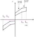
图11d是与图11c的连接件板配对的一维连接件板的平面图,Figure 11d is a plan view of a one-dimensional connector plate mated with the connector plate of Figure 11c,
图11e是图11c的板的透视图,Figure 11e is a perspective view of the plate of Figure 11c,
图11f是图11d的板的透视图,Figure 11f is a perspective view of the panel of Figure 11d,
图11g是一维平移连接件的交替配置的平面图,Figure 11g is a plan view of an alternate configuration of one-dimensional translation links,
图12a显示在支撑框架情形中使用的一维平移连接件变形体的侧视图,Figure 12a shows a side view of a 1D translational connector variant used in the braced frame situation,
图12b是图12a的一维平移连接件的平面图,Figure 12b is a plan view of the one-dimensional translation link of Figure 12a,
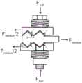
图13a-b显示对称的一维平移连接件的部分的详细视图,以展示如本文提供的公式中所描述的有关连接件的装载所涉及的力,Figures 13a-b show detailed views of portions of a symmetrical one-dimensional translation link to demonstrate the forces involved in loading the link as described in the equations provided herein,
图13c-d显示对称的一维平移连接件的部分的详细视图,以展示如本文提供的公式中所描述的有关连接件的卸载所涉及的力,Figures 13c-d show detailed views of portions of a symmetrical one-dimensional translational link to demonstrate the forces involved in unloading the link as described in the equations provided herein,
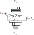
图14a-b显示不对称的一维平移连接件的部分的详细视图,以展示如本文提供的公式中所描述的有关连接件的装载所涉及的力,Figures 14a-b show detailed views of parts of an asymmetric one-dimensional translation link to demonstrate the forces involved in loading the link as described in the equations provided herein,
图14c-d显示不对称的一维平移连接件的部分的详细视图,以展示如本文提供的公式中所描述的有关连接件的卸载所涉及的力,Figures 14c-d show detailed views of parts of an asymmetric one-dimensional translational link to demonstrate the forces involved in unloading the link as described in the equations provided herein,
图15a-b显示在连接件只受拉或受压时允许相对运动的情况下一维平移连接件的两个变形体的视图,Figure 15a-b shows views of two deformed bodies of a 1D-translated link where relative motion is allowed when the link is only in tension or compression,
图16a显示图3a的一维平移连接件的部分透视图,以图示说明倾斜的表面,Fig. 16a shows a partial perspective view of the one-dimensional translating link of Fig. 3a to illustrate inclined surfaces,
图16b显示图3a的倾斜表面的变形体,Figure 16b shows a variant of the inclined surface of Figure 3a,
图17是一维平移连接件的视图,其图示说明倾斜表面不一定是菱形的并且可以弧形代替,Figure 17 is a view of a one-dimensional translational link illustrating that the sloped surfaces are not necessarily rhomboid and can be arcuate instead,
图18a-c显示弯曲表面连接,接触点处的切线可随着静止位置的位移而改变,Figure 18a–c shows curved surface connections, the tangent at the contact point can change with the displacement of the rest position,
图19显示一维平移连接件的另一个变形体,Fig. 19 shows another variant of the one-dimensional translation link,
图20显示建筑结构的示意图,其中提供一维平移连接件以及旋转连接件,每一个所述连接件用作地板至墙的连接,Figure 20 shows a schematic view of a building structure, wherein one-dimensional translational links are provided as well as rotary links, each of which serves as a floor-to-wall connection,
图21a-b显示旋转连接件的上板和下板的内面的透视图,Figures 21a-b show perspective views of the inner faces of the upper and lower plates of the swivel joint,
图22a-b显示旋转连接件的上板和下板的内面的视图,Figures 22a-b show views of the inner faces of the upper and lower plates of the swivel joint,
图22c显示以方向A看到的图22a的板的边缘,Figure 22c shows the edge of the plate of Figure 22a seen in direction A,
图22d-e显示所组装的旋转连接件在位移情况下和没有位移情况下的透视图,Figure 22d-e shows perspective views of the assembled swivel joint with and without displacement,
图22f-g显示图22e的板的透视剖视图和部分剖视图,Figures 22f-g show perspective cutaway and partial cutaway views of the plate of Figure 22e,
图22h-k显示旋转连接件的另一实施例的上板和下板的内面的视图,Figures 22h-k show views of the inner faces of the upper and lower plates of another embodiment of a swivel joint,
图23显示在已经控制剪力墙抬高的情形下,使用旋转连接件的地板剪力墙连接,Figure 23 shows a floor shear wall connection using swivel connectors where the shear wall elevation has been controlled,
图24和图25显示二维平移连接件的上板和下板的示意图,Figure 24 and Figure 25 show schematic diagrams of the upper and lower plates of the two-dimensional translation connector,
图26a和图26b显示二维平移连接件的上板和下板的透视图,Figures 26a and 26b show perspective views of the upper and lower plates of the two-dimensional translational linkage,
图27是使用结合的旋转连接件和一维或二维平移连接件的组合,来控制剪力墙的旋转和抬高的地板剪力墙连接的示意图,Fig. 27 is a schematic diagram of a floor shear wall connection to control the rotation and elevation of a shear wall using a combination of a combined rotational connector and a one-dimensional or two-dimensional translational connector,
图28显示墙示意图,所述墙使用了没有控制旋转或抬高的先前技术解决方案,从而导致横梁不良弯曲,Figure 28 shows a schematic diagram of a wall using a prior art solution without controlled rotation or elevation, resulting in undesirable bending of the beams,
图29显示墙示意图,所述墙使用了旋转和抬高都被控制的结合的旋转连接件和二维连接件,Figure 29 shows a schematic diagram of a wall using a combined swivel link and two-dimensional link with both rotation and elevation controlled,
图30显示使用单个二维平移连接件的一部分结构的侧视图,Figure 30 shows a side view of a part of the structure using a single two-dimensional translation link,
图31显示使用两个二维平移连接件的一部分结构的侧视图,Figure 31 shows a side view of a part of the structure using two two-dimensional translational links,
图32a显示两个元件之间的接头的示意图,所述两个元件使用两个旋转连接件,以便允许围绕垂直轴旋转,Figure 32a shows a schematic diagram of a joint between two elements using two swivel connections in order to allow rotation about a vertical axis,
图32b显示图32A的扩展视图,Figure 32b shows an expanded view of Figure 32A,
图32c显示图32a的部分的侧视图,Figure 32c shows a side view of the portion of Figure 32a,
图33显示两个元件之间的接头的示意图,所述元件使用两个旋转连接件,以便允许围绕水平轴旋转,Figure 33 shows a schematic diagram of a joint between two elements using two swivel connections in order to allow rotation about a horizontal axis,
图34显示两个元件之间的接头的示意图,所述元件使用一个垂直旋转连接件和两个水平一维平移连接件,以便允许围绕水平轴的相对旋转和在水平方向上相对平移,Figure 34 shows a schematic diagram of a joint between two elements using one vertical rotational connection and two horizontal one-dimensional translational connections in order to allow relative rotation about a horizontal axis and relative translation in the horizontal direction,
图35显示两个元件之间的接头的示意图,所述元件使用一个垂直的旋转连接件和两个水平的二维平移连接件,以便允许围绕水平轴的相对旋转和在水平方向与朝向页面方向上的相对平移,Figure 35 shows a schematic diagram of a joint between two elements using one vertical rotational link and two horizontal two-dimensional translational links in order to allow relative rotation about a horizontal axis and between the horizontal and page-facing directions The relative translation on
图36显示两个元件之间的接头的示意图,所述元件使用三个旋转连接件,从而允许围绕水平轴和垂直轴旋转,Figure 36 shows a schematic diagram of a joint between two elements using three swivel connections allowing rotation about horizontal and vertical axes,
图37显示两个元件之间的接头的示意图,所述元件使用两个二维平移连接件,从而允许在水平方向和朝向页面方向的相对运动,Figure 37 shows a schematic diagram of a joint between two elements using two two-dimensional translational links allowing relative movement in the horizontal direction and toward the page,
图38显示两个元件之间的接头的示意图,所述元件使用两个一维平移连接件和两个旋转连接件,以便允许在水平方向的相对运动和围绕垂直轴的旋转,Figure 38 shows a schematic diagram of a joint between two elements using two one-dimensional translational links and two rotational links in order to allow relative movement in the horizontal direction and rotation about a vertical axis,
图39显示两个元件之间的接头的示意图,所述元件使用垂直的二维平移连接件、垂直的旋转连接件和两个水平的一维平移连接件,从而允许在三个方向上的相对运动和围绕水平轴的旋转,Figure 39 shows a schematic diagram of a joint between two elements using a vertical 2D translational link, a vertical rotational link and two horizontal 1D translational links allowing relative movement in three directions. movement and rotation about a horizontal axis,
图40显示两个元件之间的接头的示意图,所述元件使用两个垂直的旋转连接件和两个一维平移连接件,以便允许围绕水平轴的旋转和在水平方向上的相对运动,Figure 40 shows a schematic diagram of a joint between two elements using two vertical rotational links and two one-dimensional translational links in order to allow rotation around a horizontal axis and relative movement in the horizontal direction,
图41显示两个元件之间的接头的示意图,所述元件使用两个垂直的旋转连接件和两个水平的二维平移连接件,以便允许围绕水平轴的旋转和在水平方向与朝向页面方向上的相对运动Figure 41 shows a schematic diagram of a joint between two elements using two vertical rotational links and two horizontal two-dimensional translational links in order to allow rotation around a horizontal axis and in the horizontal and towards-page directions Relative motion on
图42显示两个元件之间的接头的示意图,所述元件使用一个垂直旋转连接件,以便允许只围绕水平轴的旋转,以及Figure 42 shows a schematic diagram of a joint between two elements using a vertical swivel connection to allow rotation about a horizontal axis only, and
图43显示使用两个一维连接件的组件,Figure 43 shows an assembly using two 1D connectors,
图44a-c显示两个结构部分的视图,所述结构部分由一维平移连接件以各种不同方式连接,Figures 44a-c show views of two structural parts connected in various ways by a one-dimensional translational link,
图44d显示在支撑连接上额外施加一维连接件,Figure 44d shows the additional application of a 1D link on the support link,
图45a显示示例性施加两个连续结合的一维连接件以形成结构接头,Figure 45a shows an exemplary application of two successively bonded one-dimensional connectors to form a structural joint,
图45b显示图45a的结合接头的力-位移特征的实例,Figure 45b shows an example of the force-displacement characteristics of the bonded joint of Figure 45a,
图45c针对图45a所示的结合接头的变形体显示力-位移特征的实例,Figure 45c shows an example of force-displacement characteristics for the deformation of the joint joint shown in Figure 45a,
图46a显示具有位移感测器的一维连接件,以测量第一元件和第二元件之间的位移,Figure 46a shows a one-dimensional connection with a displacement sensor to measure displacement between a first element and a second element,
图46b显示具有位移感测器的一维连接件,以测量第三元件的板之间的位移,Figure 46b shows a one-dimensional connection with displacement sensors to measure the displacement between the plates of the third element,
图46c显示示例性感测和数据传输以及针对位移感测器数据的存储网络。Figure 46c shows exemplary sensing and data transmission and storage network for displacement sensor data.
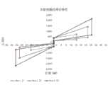
图47显示一维连接件预测的理论性能与实际测试性能的力-位移比对图。Figure 47 shows the force-displacement plot of predicted theoretical performance versus actual test performance for a 1D connector.
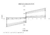
图48是力对位移的绘图,其显示改变倾斜表面的角的效果。Figure 48 is a plot of force versus displacement showing the effect of varying the angle of an inclined surface.
图49是力对位移的绘图,其显示在倾斜表面之间不同摩擦系数的效果。Figure 49 is a plot of force versus displacement showing the effect of different coefficients of friction between inclined surfaces.
图50是力对位移的绘图,其显示增加串联的偏向垫圈数目的效果。Figure 50 is a plot of force versus displacement showing the effect of increasing the number of deflection washers in series.
图51是力对位移的绘图,其显示增加并联的垫圈数目的效果。Figure 51 is a plot of force versus displacement showing the effect of increasing the number of washers in parallel.
图52是力对位移的绘图,其显示增加弹性固定螺栓的数目的效果。Fig. 52 is a plot of force versus displacement showing the effect of increasing the number of elastic set bolts.
图53是力对位移的绘图,其显示增加弹性固定件的螺栓预应力的效果。Figure 53 is a plot of force versus displacement showing the effect of increasing the bolt prestress of the elastic mount.
具体实施方式Detailed ways
在本发明中,随后将在本文中描述其细节和变形体,通过板之间的摩擦,针对位置复原能力以及建筑物或结构的阻尼移动,来组织并布置元件。In the present invention, the details and variants of which will be described later herein, the elements are organized and arranged by friction between plates for positional resilience and damped movement of the building or structure.
本文所述的连接件可用于很多建筑应用中。连接件以优选形式被设想成用于建筑结构中,并且这是本文将详细描述的应用。连接件还被设想成用于其他结构上,诸如桥梁、高塔、建筑立面和其他大规模或较小规模的结构。连接件能够用于许多情形中,包括工业上的架设棚架,或任何其他希望在结构部件与自动定心之间有顺应性的情形。进一步地,连接件适用于钢材、水泥、木材,或混合结构以及柱形物与横梁,柱形物与地基,支撑或剪力墙连接。The connectors described herein can be used in many construction applications. In a preferred form the connector is contemplated for use in building structures and this is the application which will be described in detail herein. Connectors are also contemplated for use on other structures such as bridges, towers, building facades and other large or small scale structures. The connectors can be used in many situations, including industrial scaffolding, or any other situation where compliance between structural components and self-centering is desired. Further, the connector is suitable for steel, cement, wood, or mixed structures, as well as columns and beams, columns and foundations, supports or shear walls.
一维连接件One-dimensional connector
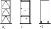
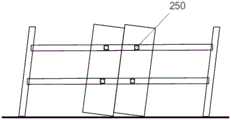
首先,我们将描述一些基本形式的连接件,其允许在连接所述基本形式连接件的元件之间的一维(本文也称为1D)相对移动。此类一维连接件1的实例,例如,可用于图1a-1c中所示的情形。在图1a中,所示的连接件1被用于支撑框架情形。在图1b中,所示的连接件1处于对抗框架情形的时刻。在图1c中,所述连接件被用作剪力墙的压紧装置。First, we will describe some basic forms of connectors that allow one-dimensional (herein also referred to as ID) relative movement between the elements connecting the basic forms of connectors. An example of such a one-
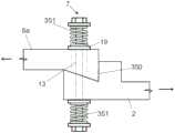
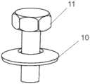
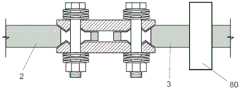
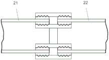
参考图2a和图2b,图示说明一维连接件的简单形式。在此配置中,通过弹性固定件7将第一元件2与第二元件3固持在一起。第一元件2和第二元件3各自具有互补的倾斜表面18。倾斜表面18与第一元件2和第二元件3成倾斜的角度,且能够通过彼此上方的互补面的滑动相对于彼此移动(如箭头所指示的)。Referring to Figures 2a and 2b, a simple form of a one-dimensional connector is illustrated. In this configuration, the
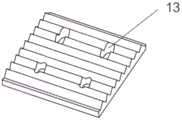
元件2和元件3中的任何一个包含插槽13,允许其相对于弹性固定件7垂直地移动。第一元件2可进一步包含止动面350,以防止彼此上方的互补面进一步滑动通过中间位置。或者,第一元件可不包含止动面350,而是当连接件处于中间位置时,插槽13的长度可以是像作用于弹性固定件7的轴上一样,因此防止滑动通过中间位置。Either of
垫圈19可与第一元件2和第二元件3的外表面相邻。在任一元件都设有插槽13的情况下,垫圈19的尺寸大于插槽的尺寸。当带插槽的元件相对于弹性固定件7移动时,垫圈19将相对于那个元件的表面滑动。The
在垫圈19与弹性固定构件7的端部之间,可设有一些形式的偏向构件,用于将两个元件的倾斜表面彼此结合。在图2a中,偏向构件被图示为垫圈,诸如膜片式弹簧垫圈10。在图2b中,偏向构件351被图示为弹簧部件。Between the
连接件1,就其本身而言(或此外,类似连接件或在两个部件之间产生连接的其他方法)将有助于确保两个部件2和部件3十分刚性又弹性地连接在一起。也就是说,优选地,连接件将提供较高初始刚度的连接并有效提供刚性连接,直至达到两个元件之间的临界力。此临界力在本文中被称为Fslip这是使连接件产生位移并允许两个部件相对于彼此移动所需的力。The
举例来说,这可发生于两个部件2和3的地震荷载(或其间其他诱发振荡的移动)期间。For example, this may occur during seismic loading of the two
重要的是,本发明的连接件能够通过自感应恢复力来消散能量(因此,显著地减少地震荷载),使连接偏向且优选地返向其初始状态。因此,一旦停止外部负载(例如,地震现象),弹性接头便会自动定心。Importantly, the connection of the present invention is capable of dissipating energy (thus, significantly reducing seismic loads) through self-induced restoring forces that deflect and preferably return the connection to its original state. As a result, the elastic joint is self-centering as soon as the external load is stopped (for example, seismic phenomena).
参考图3,图示说明本发明连接件的一些优选形式。Referring to Figure 3, some preferred forms of the connector of the present invention are illustrated.
形式中的连接件可包含第一元件2和第二元件3。如图1b所示,第一元件2可固定至第一部件(诸如建筑结构的柱形物4a)并且第二元件3可连接至第二部件(诸如建筑结构的横梁4b)。夹紧组件或弹性固定件7将组件固持在一起。如本文描述的一些变形体,可能不是第二元件(如图3c中所图示的操作)。The connection in form may comprise a
连接件1,就其本身而言或另外与类似连接件或在两个部件之间产生连接的其他方法,将有助于确保两个部件2和部件3十分坚硬又弹性地连接在一起。The
优选地,连接件将提供较高初始刚度的连接并提供刚性连接,直至达成两个元件之间的临界力。此临界力在本文中被称为Fslip。这是使连接件允许两个部件产生相对于彼此位移所需的力。Preferably, the connector will provide a connection of higher initial stiffness and provide a rigid connection until a critical force between the two elements is reached. This critical force is referred to herein as Fslip . This is the force required for the joint to allow displacement of the two parts relative to each other.
本发明的连接件能够通过自感应恢复力(由固定件7所提供)来消散能量(因此,显著地减少地震荷载),将连接偏向且优选地返向其初始状态。The connection of the present invention is capable of dissipating energy (thus significantly reducing seismic loads) through self-induced restoring forces (provided by the fixings 7), biasing and preferably returning the connection to its original state.
参照图3和图5,可以看出,优选地,连接件的第一元件2和第二元件3至少部分搭接在第三元件6的上方或下方。以优选形式,在第一元件和第二元件各自的侧边(对称状况)提供有两种此类第三元件6a和6b。优选地,此类第三元件6a和6b作用于第一元件2和第二元件3上的相反方向。Referring to FIGS. 3 and 5 , it can be seen that, preferably, the
然而,在图8和图9所示的变形体中,只可使用一个第三元件6(不对称的状况)。设想使用多对第三元件,每对的各个元件可作用于相反方向。However, in the variant shown in FIGS. 8 and 9 only one
优选形式的弹性固定件7可被认为是弹性可扩展的夹具,所述夹具夹紧、获取及/或夹持第一元件2和第二元件3。A preferred form of
在优选形式中,第一元件和第二元件是类似板状的形状。所述元件通常是细长又扁平的,将在随后的下文中描述其细节。In a preferred form, the first and second elements are plate-like in shape. The elements are generally elongated and flat, the details of which will be described later on.
参见图3a和图3b,第一元件和第二元件能够在x方向上相对于第三元件6移动。仅除了第三元件6的此类移动所引起的横向移动,这种相对移动优选地被限定在这种方向上。弹性可扩展的夹具7在横向于x方向和优选地z方向的方向上是可扩展的。横向膨胀优选地是线性的,但可设想在发生至少一些旋转位移的情况下使用机械装置。Referring to Figures 3a and 3b, the first and second elements are movable relative to the
在图3a、图3b和图5展示为组件的优选形式中,在两个第三元件6a和6b之间获取第一元件2和第二元件3。所述元件是相接的相互关系且通过至少一个弹性固定件7保持处于那样的关系。In the preferred form shown as an assembly in Figures 3a, 3b and 5, the
以优选形式,提供多个弹性固定件7。弹性固定件优选地包括带螺纹的紧固件,诸如螺栓8和螺母9。如图3a所见,螺栓8延伸通过第一元件或第二元件与第三元件的组件。优选地,获取至少一个偏向构件以作为组件一部分。例如,这可以膜片式弹簧垫圈或弹簧10的形式。例如,此类垫圈是通过螺栓的头部与第一元件或第二元件和第三元件的组件之间的螺栓头部11所获得的。以优选形式,垫圈作用于螺栓11或螺母9的头部并对着相邻第三元件6。优选地,在各个螺栓头部11及/或螺母9相邻处设有至少一个垫圈10(如图6中所示的)。In a preferred form, a plurality of
以优选形式,提供多个此类垫圈10并被设在元件的组件的各个侧边,如图3b和图7所见。提供垫圈以允许弹性固定件7对元件的组件施加压力。这直接关系到组件移动的摩擦阻力,以及偏向力。弹性固定件7的拉紧/松动提供了一种简单的机制,来实现调整夹紧力,以便满足接头的设计标准。In preferred form, a plurality of
适当选择垫圈将会允许在元件的组件上提供适当的膨胀范围并且施加压力。Proper selection of gaskets will allow for the proper range of expansion and exertion of pressure on the assembly of elements.
在替代形式中,外部弹簧351例如可直接接合两个第三元件6a和6b并使两个第三元件6a和6b偏向彼此。In an alternative form, the
如图3b所示的,力Fpr可视为作用于组件上。弹性固定件7允许元件组件横向膨胀。这种膨胀与弹性固定件所提供的弹性力的方向平行。优选地,每个弹性固定件的压力与螺栓的轴共轴。优选地,压力与弹性可扩展的夹具的第一部件/第二部件之间的相对移动方向垂直。压力与弹性可扩展夹具的膨胀/收缩的方向平行。As shown in Figure 3b, the force Fpr can be considered to act on the assembly. The
以优选形式,在第一元件和第二元件各自上使用有至少一个弹性固定件。在图3b中,第一元件2和第二元件3各自显示有两个固定件7,一共有4个固定件。连接件围绕对称轴RR的对称设计(如图3b所见)将有助于在负载时防止剪切力引入螺栓上。In preferred form, at least one resilient fastener is used on each of the first and second elements. In Fig. 3b, the
夹具从其静止位置的膨胀(如图3b所见)是由第一元件2或第二元件3的一个或两个与夹具之间的相对移动(优选地,在垂直于夹紧力Fpr的方向上)引起的。由于第三元件6和相应的第一元件2和第二元件3彼此具有互相倾斜的关系,因此在两个元件之间会引起倾斜运动,从而发生了膨胀。当对第一部件和第二部件施加足够大的力Fslip以将部件拉开,或朝向彼此推动部件时,发生第一元件或第二元件的一个或两个与夹具之间的相对移动。Expansion of the clamp from its rest position (as seen in Fig. 3b) is caused by a relative movement between one or both of the
图13a和图13b中可看出元件组件的横向膨胀和收缩。The lateral expansion and contraction of the element assembly can be seen in Figures 13a and 13b.
如图13a中可见,在其中存在两个第三元件6a和6b的情况下所示的实例中,观察到在第二元件3移动的时候,两个第三元件6a和6b之间发生彼此远离的位移。第二元件3的移动(其是由对第二元件3施加的滑动力所引起的)使第三元件6a和6b在平行于弹性固持(例如夹紧力Fpr)方向的方向上彼此远离位移,所述弹性固持是通过弹性固定件7施加的。As can be seen in Figure 13a, in the example shown in the case where there are two
以优选形式,通过第一元件和第二元件的每一个以及第三元件的区域提供至少一个,并且优选地多个互补形状的倾斜表面,第一元件和第二元件分别与第三元件接合。In a preferred form, at least one, and preferably a plurality of complementary shaped inclined surfaces are provided by each of the first and second elements and a region of the third element which respectively engages the third element.
优选地,第一元件和第二元件的每一个呈现斜面阵列,所述阵列在X方向上延伸。斜面是连续地上下斜面。所述斜面在X-X方向上延伸成阵列。优选地所述斜面每一个具有相同的配置。Preferably, each of the first element and the second element presents an array of sloped surfaces, the array extending in the X direction. The slope is a continuous up and down slope. The slopes extend in an array in the X-X direction. Preferably said ramps each have the same configuration.
以优选形式,如图5和图16a所见的,倾斜表面18是平面的。In a preferred form, as seen in Figures 5 and 16a, the
以替代形式,如图17、图15、图16b和图18所见的,倾斜表面的轮廓是圆的、顶端扁平的齿形,或波形。参考图18,对于波形的情况,可看出,接触点处的切线5的角度随着静止位置的位移而改变。这对改变移动的阻力有影响。Alternatively, as seen in Figures 17, 15, 16b and 18, the profile of the inclined surface is rounded, flat-tipped toothed, or undulating. Referring to Figure 18, for the waveform case, it can be seen that the angle of the tangent 5 at the point of contact changes with displacement of the rest position. This has the effect of changing the resistance to movement.
因此,需要恰当设计接触表面的形状和滑动限制器,以便确保期望的性能。Therefore, the shape of the contact surface and the slip limiter need to be properly designed in order to ensure the desired performance.
以优选形式,元件的连接表面轮廓优选地呈平行规则的表面,其中假想的平行线面向一个方向,以助于在相对移动的范围中第三元件与各个第一元件和第二元件之间保持面对面的表面积接触,而不是点接触。优选地,任何轮廓形式的平行规则的表面具有平行于x-y平面运行的假想的规则表面线。In a preferred form, the connecting surface profiles of the elements are preferably parallel regular surfaces with imaginary parallels facing in one direction to facilitate retention between the third element and the respective first and second elements in the range of relative movement. Face-to-face surface area contact, not point contact. Preferably, parallel regular surfaces of any profile form have imaginary regular surface lines running parallel to the x-y plane.
图16b中所示的实例中,第三元件6b的斜面轮廓看起来是锋利齿形的横断面。这有助于保持元件的纵向对齐。或者或此外,Z方向上插槽13的固定件(例如,螺栓)的滑动配合有助于保持第一元件和第二元件与第三元件纵向对齐。In the example shown in Figure 16b, the beveled profile of the
以替代形式,如图11g所示的,每一个第三元件6a和6b(而不是第一元件2和第二元件3)中设有插槽13。在此配置中,各个弹性固定件7和第三元件6a和6b的相邻处设有直径大于插槽13的垫圈19。在第一元件2和第二元件3之间相对运动的情况下,弹性固定件7将与第一元件和第二元件中的每一个一起移动,且将沿着第三元件6a和6b中相应的插槽13进行滑动。Alternatively, a
随着弹性固定件相对于插槽13进行移动,滑动垫圈19将被驱动至第三元件6a和6b的表面。以此形式,滑动垫圈19在垫圈10的偏向力下对着第三元件6a和6b的面的相对运动对第一元件2与第二元件3之间的相对运动提供了额外的阻力。在此配置,其中在第三元件6a和6b中设有插槽13的情况下,总阻力将是相同配置的不对称连接件的阻力的两倍。As the elastic mount moves relative to the
然而,以此形式,通过滑动垫圈19对着第三元件的面的相对运动所提供的阻力不会提供使连接件偏向其初始状态的恢复力。因此,以此方式,可使用倾斜表面18较大的角θ,以便增加恢复力。In this form, however, the resistance provided by the relative movement of the sliding
针对第一元件、第二元件和第三元件选择的适当材料将确保在元件之间存在适当的摩擦性。当移动时,元件组件的元件之间的摩擦将在第一部件与第二部件之间提供阻尼运动,其中滑动连接件与第一部件和第二部件结合。阻尼程度取决于摩擦系数、穿过接头膨胀的横向距离,以及其他因素,包括相关弹性固定件提供于元件组件上的弹性固持力。Proper material selection for the first, second and third elements will ensure proper friction between the elements. When moving, the friction between the elements of the element assembly will provide a damped movement between the first part and the second part with which the sliding connection engages. The degree of damping depends on the coefficient of friction, the lateral distance through which the joint expands, and other factors, including the elastic retention provided by the associated elastic fasteners on the element assembly.
预期,接头的相关滑动表面可润滑及/或设置有专门涂层,以便控制磨损。可用允许保持相当高的摩擦系数的各种润滑脂产品,所述相当高的摩擦系数是便于提供充足阻尼的理想特征。It is contemplated that the relevant sliding surfaces of the joints may be lubricated and/or provided with special coatings in order to control wear. Various grease products are available that allow maintaining a relatively high coefficient of friction, a desirable feature in order to provide adequate damping.
如可见地,倾斜表面的方向交替并且这样允许连接件在两个方向上吸收两个部件(例如,建筑结构部件)的运动。因此,力Fslip可以是正向力或负向力(如图4中所图示的)。As can be seen, the direction of the inclined surfaces alternates and this allows the connection to absorb movements of the two parts (eg building structural parts) in both directions. Thus, the force Fslip can be a positive force or a negative force (as illustrated in FIG. 4 ).
以便允许连接件仍然是组件,优选地所述连接件是在方向Fslip上延伸的伸长形状,弹性固定件7优选地延伸穿过第三元件的小孔12并也穿过第一元件和第二元件的插槽13。插槽13尺寸被调整为允许在第三元件相对于第一元件和第二元件的一个或两个的伸长方向上相对移动。插槽和固定件可配置为限制移动的范围,以防止组件移动造成的棘齿形。结果,在活动期间多对连接的倾斜表面18将仍然是一对倾斜表面且将不会与相邻倾斜表面挂钩。插槽13可提供终点止动功能以防止此类的棘齿形。或者,可通过弹性固定件来界定滑动运动的限制,所述弹性固定件可防止第一元件和第二元件分离成以其他方式允许倾斜表面形成棘齿形的程度。举例来说,可设置螺栓头11和螺母9之间的距离以限制第三元件6a和6b之间的分离程度,从而限制第一元件和第二元件在x方向上的运动范围。本文随后描述的锯齿形配置也会提供此类限制装置。In order to allow the connection piece to remain an assembly, preferably said connection piece is of elongate shape extending in direction Fslip , the
通过适当选择具有所要摩擦系数的材料,选择倾斜表面的角θ,适当选择弹性固定件的特性,在从图13a中所示的静止位置位移之后,为了通过施加力Fslip达成图13b所示的位移条件,将会使第二元件相对于第三元件这样的位移往回朝其静止位置偏向。By appropriate selection of a material with the desired coefficient of friction, selection of the angle θ of the inclined surface, selection of the properties of the elastic mount, after displacement from the rest position shown inFIG . The displacement condition will cause such a displacement of the second element relative to the third element to bias back towards its rest position.
将理解,对于给定的摩擦系数和夹紧力Fpr,角θ的增加将造成通过第三元件增加施加至第一元件或第二元件的力,从而使其往回偏向静止位置。在第一部件和第二部件可经受的振荡活动中,参考图4可看出会发生阻尼。如图4所示,当接头的负载达到滑动力的临界值时接头开始变形。随着接头继续膨胀,滑动表面之间的摩擦阻力由于螺栓的夹紧力变大而增加。接头的此类加固将会在膜片式弹簧垫圈完全锁定的时刻下中断。在从接头卸载之后,接头自动定心至其初始位置。It will be appreciated that for a given coefficient of friction and clamping force Fpr , an increase in the angle Θ will cause an increase in the force applied by the third element to the first or second element, thereby biasing it back toward the rest position. In the oscillatory activity to which the first part and the second part may be subjected, it can be seen with reference to Figure 4 that damping occurs. As shown in Fig. 4, the joint starts to deform when the load on the joint reaches the critical value of sliding force. As the joint continues to expand, the frictional resistance between the sliding surfaces increases due to the greater clamping force of the bolts. Such reinforcement of the joint will be interrupted at the moment the belleville washer is fully locked. After unloading from the joint, the joint is automatically centered to its initial position.
通过焊接及/或机械紧固(或其他方式),第一元件和第二元件可容易地并入建筑结构。所述元件的延长方向被排成一行以在其所关联的第一元件和第二元件之间的振荡运动期间通过适当方式分解推力并提供消耗能量的机能以及提供自动定心的能力。The first element and the second element can be easily incorporated into the building structure by welding and/or mechanical fastening (or otherwise). The direction of elongation of the elements is aligned to resolve thrust forces in an appropriate manner and to provide energy-dissipating functionality during oscillatory motion between their associated first and second elements and to provide self-centering capabilities.
使本文的接头配置变得简单又易于实施的一个重要特征在于:所述连接件是如图3所见的薄型的,其中提供多个倾斜表面18。类似地,垫圈型(诸如膜片式弹簧垫圈)偏向构件10的优势在于可以相对浅薄的形式提供适量的夹紧力。An important feature that makes the joint configuration here simple and easy to implement is that the connector is of low profile as seen in FIG. 3 , wherein a number of
本发明的连接件优选地是细长型的,使得其特别适用于建筑行业。其狭小的轮廓允许其很容易地定位于有限的空间。通过调整弹性固定件的尺寸以及第一元件和第二元件以及第三元件的厚度来决定其厚度(y方向上)。同时,增加角θ可有助于针对弹性固定件所施加的任何给定弹性固持力提供较高程度的阻尼,此类角的增加也会增加组件的厚度。因此希望使角度最小化。针对给定的应用,可参考本文随后所述的计算The connector of the invention is preferably of elongated type, making it particularly suitable for use in the construction industry. Its narrow profile allows it to be easily positioned in confined spaces. Its thickness (in the y direction) is determined by adjusting the size of the elastic fixing member and the thicknesses of the first element, the second element and the third element. Whilst increasing the angle Θ can help provide a higher degree of damping for any given elastic holding force applied by the elastic mount, such an increase in angle will also increase the thickness of the assembly. It is therefore desirable to minimize the angle. For a given application, refer to the calculations described later in this paper
选择斜面的角度,以使得在振荡运动期间的卸载时刻,由随后加载膜片式弹簧垫圈所引起或放大的转向力大于作用在连接滑动表面之间的摩擦阻力。这提供消耗能量的弹性行为并且提供连接件的自动定心能力以使连接件往回朝向其静止状况偏向。The angle of the ramp is chosen such that at the moment of unloading during the oscillating movement, the deflection force induced or amplified by the subsequent loading of the spring washer is greater than the frictional resistance acting between the connecting sliding surfaces. This provides an elastic behavior that dissipates energy and provides a self-centering capability of the link to bias the link back towards its rest condition.
参考图8和图9可以看出,可以提供本发明的变形体。在此变形体中,只提供一个倾斜的第三元件。针对第一元件和第二元件与第三元件相对侧上的各个螺栓可提供平顶帽型的板30。平顶帽型的板30本身在没有自动定心功能下只提供摩擦阻力和阻尼。提供第二倾斜的第三元件增加了连接件的自动定心。同样增强了阻尼效应。图10中显示了变形体,其中针对各个螺栓(而非板30)提供单个垫圈19。Referring to FIGS. 8 and 9, it can be seen that variants of the present invention can be provided. In this variant, only one inclined third element is provided. A
如果在第一元件和第二元件之间的连接处需要额外的阻尼,那么可提供多个并联连接件。例如在图1b和图1c中显示并联的连接件。If additional damping is required at the connection between the first element and the second element, multiple parallel connections can be provided. Parallel connections are shown, for example, in FIGS. 1b and 1c.
如果在第一部件和第二部件之间位移增加,那么可提供多个串联的连接件。这样可增加串联连接的连接件的伸长量。图3的连接件是每个侧边能够移动的串联连接件。因此就本文随后阐述的来说,针对图3b中所示的连接件,nj等于2。If the displacement increases between the first part and the second part, multiple connections in series may be provided. This increases the elongation of the connectors connected in series. The link of Figure 3 is a serial link with each side movable. Thus nj equals 2 for the connection shown in FIG. 3 b as explained later herein.
图3c和图3d显示单数形式的连接件。此处,元件6a和6b可相对于部件3纵向地以及横向地移动,但只针对横向方向上的相对移动部件61进行固定。可使用轴承销60来允许元件6a和6b和61之间的此类移动。Figures 3c and 3d show connectors in the singular. Here, the
参考图11a和图11b可看出,可在推力不平行于所述连接件的延长方向的情形下使用本发明的代替连接件。在图11a所示的实例中,连接件1的延长方向LL与推力X成角度,所述推力X经过支撑部件20。在此排列中,例如,第三连接件6固定至结构的横梁31并且第一元件2固定至支撑部件20,所述支撑部件20在与所述连接件的方向LL成角度处从第一元件延伸。可使用轴承销70以允许第一元件2的横向移动。因此,通过支撑部件20在方向X上施加的力将会成一角度。然而,本发明的连接件能够分解这种力以允许支撑件在连接件的方向LL上的位移。图12a和图12b显示了此种排列的替代方式,其中延长连接件的两个方向LL平行于推力X,所述推力X可经过支撑部件20。As can be seen with reference to Figures 11a and 11b, the alternative connection of the present invention can be used in situations where the thrust is not parallel to the direction of elongation of said connection. In the example shown in FIG. 11 a , the direction of extension LL of the
以优选形式,螺栓优选地是高强度螺栓,且用于至少第一元件和第二元件的材料是贝斯钢板TM。优选地,第三元件是软钢。已发现,贝斯钢板TM与软钢一起提供统一的摩擦性能。In a preferred form, the bolts are preferably high strength bolts and the material for at least the first and second elements is Bass Plate™ . Preferably, the third element is mild steel. Bass Plate™ has been found to provide uniform friction properties with mild steel.
在一维连接件的建造中,第一元件2和第二元件3的末端厚度可以小于、等于或大于斜面的幅值。In the construction of a one-dimensional connection, the end thicknesses of the
图15a和图15b显示了一维连接件的代替实施例。根据此实施例,第一元件2和第二元件3以及第三元件6a、6b的互补配合表面可具有倾斜表面18和附加表面5,所述倾斜表面18在一个方向上允许表面在彼此上方滑动,并且所述附加表面5在驱动第一元件和第二元件以在相反方向移动时防止此类附加表面的相对滑动,从而防止此类相反方向的移动。Figures 15a and 15b show an alternative embodiment of a one-dimensional connector. According to this embodiment, the complementary mating surfaces of the
这允许连接件只在一个方向上从第一部件和第二部件中其所连接的原来状况位移。这可能是膨胀或收缩。This allows the connection to be displaced in only one direction from its original condition in the first and second parts to which it is connected. This could be expansion or contraction.
在图15a中,倾斜表面18被排列成使得第一元件和第二元件可相对于彼此向外移动,但不可以远离最初的静止位置向内移动。在图15b中,倾斜表面18被排列成使得第一元件和第二元件彼此向外移动,但不可以远离其最初的静止位置向外延伸。In Fig. 15a, the
单向的一维连接件的应用可以是剪力墙,其中墙与较低的固定点之间的延伸是所希望得到的,但是那些两个点朝向彼此的移动是不希望的。An application for a unidirectional one-dimensional connector may be a shear wall where extension between the wall and a lower fixed point is desired, but movement of those two points toward each other is undesirable.
二维连接件2D Connector
参考图24-图26b,显示了2D弹性平移的滑动摩擦连接件元件。参考图24,第一元件202以平面图展示,且在图25中,展示了第一夹紧元件206a。这样的两个元件具有互补的配合表面,所述配合表面不仅在第一方向(诸如方向XX)上提供倾斜表面,还在方向YY上提供倾斜表面。因此,这些元件的组件可以允许满足结构的二维相对平移。Referring to Figures 24-26b, a 2D elastically translating sliding friction joint element is shown. Referring to Figure 24, the
如以上参考连接件的1D实施例所描述的,以类似方式使用螺栓和垫圈(或弹簧),来形成弹性固定件。优选地,螺栓8是高强力的,其最终产率能力是接头的强度的约两倍或更多倍。这种安全因素使得设计标准有效地排除了螺栓的故障,因为螺栓在只受拉时几乎承载了全部,且不太可能会引起故障。Bolts and washers (or springs) are used in a similar manner as described above with reference to the 1D embodiment of the connector to form the resilient fastener. Preferably, the
二维连接件可被设计成不限于只在两个正交方向上移动,而是能够在任何平移方向上以平面方式位移。这样做时,两个元件的旋转方向不会改变。因此,相对平移移动在平面上是全向性的。Two-dimensional linkages can be designed that are not limited to movement in only two orthogonal directions, but are capable of displacement in a planar manner in any translational direction. When doing so, the direction of rotation of the two elements does not change. Therefore, relative translational movement is omnidirectional in the plane.
平移的连接件(1D/2D)的设计步骤:Design steps for translational connectors (1D/2D):
基于图13和图14所示的分离体示意图,针对对称或不对称的连接件的不同条件,考虑作用在第一元件和第二元件上的力的平衡来如下概述设计步骤:Based on the schematic diagrams of the separating body shown in Figures 13 and 14, the design steps are outlined as follows, considering the balance of forces acting on the first element and the second element, for different conditions of symmetrical or asymmetrical connections:
可根据如下确定滑动力Fslip,The sliding force Fslip can be determined as follows,
i.对于对称条件:i. For the symmetric condition:
ii.对于不对称条件:ii. For asymmetric conditions:
其中in
Fb,pr是由于预应力造成的螺栓夹紧力Fb,pr is the bolt clamping force due to prestress
nb是螺栓的数目nb is the number of bolts
θ是凹槽的角度θ is the angle of the groove
μs是静摩擦系数μs is the coefficient of static friction
可如下确定残余力FresidualThe residual force Fresidual can be determined as follows
iii.对于对称条件:iii. For symmetric conditions:
iv.对于不对称条件:iv. For asymmetric conditions:
负载Fult loading和卸载Fult unloading的极限量可通过用μk、μs与Fb,u分别替换方程式(1)至(4)中的μs、μk与Fb,pr来达成的。The limit of load Fult loading and unloading Fult unloading can be achieved by replacing μs , μk and Fb,pr in equations (1) to (4) with μk , μs and F b,u respectively .
其中in
μs是静摩擦系数μs is the coefficient of static friction
μk动摩擦系数(可被视为0.6μs)μk kinetic friction coefficient (can be regarded as 0.6μs )
Fb,u是通过以下给出的螺栓上的极限力Fb,u is the ultimate force on the bolt given by
Fb,u=Fb,pr+ksΔs (3)Fb,u = Fb,pr +ks Δs (3)
其中in
ks是垫圈或弹簧堆叠的刚度ks is the stiffness of the washer or spring stack
Δs是在预应力之后垫圈或弹簧堆叠的最大挠度Δs is the maximum deflection of the washer or spring stack after prestressing
应理解should be understood
i.在单动式连接件中,板处的摩擦阻力和轴承销连接需要被添加至螺栓夹紧力Fb。i. In single acting connections, the frictional resistance at the plates and the bearing pin connection needs to be added to the bolt clamping force Fb .
ii.在不对称条件下,除了由于预应力造成的所得的拉力之外,螺栓还需要通过剪力转移接头负载。ii. Under asymmetrical conditions, the bolt needs to transfer the joint load through shear in addition to the resulting tension due to prestressing.
可通过以下表示最大横向挠度:The maximum lateral deflection can be expressed by:
其中in
nj是以串联排列的接头数目(例如,对于单动式连接件和双动式连接件而言,nj分别等于1和2)nj is the number of joints arranged in series (e.g. nj equals 1 and 2 for single-acting and double-acting joints, respectively)
为了实现自动定心性能,必须考虑以下几点:In order to achieve self-centering performance, the following points must be considered:
i.tanθ>μs(针对对称情况);(针对不对称情况)i.tanθ>μs (for symmetric cases); (for asymmetrical cases)
ii.(L是凹槽顶部和底部之间的水平距离)ii. (L is the horizontal distance between the top and bottom of the groove)
在存在0.36与0.39之间的摩擦系数的情况下,θ的角度范围可以是从针对对称条件的25-30度和针对不对称条件的高达45度。In the presence of a coefficient of friction between 0.36 and 0.39, the angle of Θ may range from 25-30 degrees for symmetric conditions and up to 45 degrees for asymmetric conditions.
如设计步骤所界定的,对倾角有最低的要求,并且如果不能满足,则不会有自动定心的性能。因此,最低要求不能根据一定限度减低。同样,由于板厚度以给定的行进范围增长,增加超出最低要求的角度也将是效率不高的。使板厚度保持下降,确保材料成本降低并且使产品更适用于有限的空间。应注意到,自动定心只取决于斜面的角度并且增加螺栓夹紧力也不会影响所述角度,即使在卸载之后所述夹紧力加快了板反向移动至静止位置。因此,最小角度θ完全以摩擦系数的函数存在的。增加弹力影响了连接件的阻尼和返回至静止位置的速度。可使用工具以确保板上初始偏向力的适当设置,亦即,由于预应力导致的螺栓夹紧力。这允许接头根据设计所需的性能进行‘调节’。As defined in the design step, there is a minimum requirement for the inclination angle, and if it cannot be met, there will be no self-centering capability. Therefore, the minimum requirements cannot be reduced according to certain limits. Also, increasing the angle beyond the minimum required would be inefficient as the plate thickness grows with a given range of travel. Keeping the board thickness down ensures lower material costs and makes the product more suitable for confined spaces. It should be noted that the self-centering is only dependent on the angle of the ramp and that increasing the bolt clamping force does not affect said angle, even though the clamping force accelerates the reverse movement of the plate to the rest position after unloading. Therefore, the minimum angle θ exists entirely as a function of the coefficient of friction. Increasing the spring force affects the damping of the joint and the speed at which it returns to the rest position. Tools can be used to ensure proper setting of the initial deflection force on the plate, ie the bolt clamping force due to prestressing. This allows the joint to be 'tuned' according to the properties required by the design.
预测值与测试数据的对比Comparison of predicted values with test data
理论上讲,上述方程式预测力与一维连接件在使用期间经过的位移。图47显示这些预测负载和卸载力与一维连接件的相关位移的比对图,其中测试数据显示为粗体,且理论计算值叠加在测试数据上方。在测试非常紧随预测值期间图形显示与连接件的加载和卸载有关的滞后回线。Theoretically, the above equations predict the force and displacement experienced by a one-dimensional connection during use. Figure 47 shows a plot of these predicted loading and unloading forces versus the relative displacement of the 1D connector, with the test data shown in bold and the theoretically calculated values superimposed on top of the test data. The graph shows the hysteresis loops related to the loading and unloading of the connector during the test very closely following the predicted value.
由于测试值和预测值之间的紧密的相互关系,可设计连接件的物理特性和材料特性以符合所要的输出推力和位移轮廓。Due to the close correlation between the measured and predicted values, the physical and material properties of the connection can be designed to match the desired output thrust and displacement profiles.
例如,图48至53显示改变各种设计参数对力与接头的位移特性的预测效果。For example, Figures 48 to 53 show the predictive effect of varying various design parameters on the force and displacement characteristics of a joint.
图48显示了改变倾斜表面的角度的效果。Figure 48 shows the effect of varying the angle of the sloped surface.
图49显示了倾斜表面之间不同摩擦系数的效果。Figure 49 shows the effect of different coefficients of friction between inclined surfaces.
图50显示了增加串联偏向垫圈数目的效果。Figure 50 shows the effect of increasing the number of biased washers in series.
图51显示了增加并联垫圈数目的效果。Figure 51 shows the effect of increasing the number of washers in parallel.
图52显示了增加弹性固定螺栓数目的效果。Figure 52 shows the effect of increasing the number of elastic fixing bolts.
图53显示了增加弹性固定件的螺栓预应力的效果。Figure 53 shows the effect of increasing the bolt prestress of the elastic fixing.
旋转连接件Rotary connector
现将描述上述连接件的进一步变形体。此变形体提出旋转的弹性滑动摩擦而不是平移滑动。如图20所示,可在墙-地板连接之间使用旋转的弹性滑动摩擦连接件。在图20中,可在此结构中于地板14和承重墙15之间使用多个旋转连接件100。Further variants of the above-mentioned connection will now be described. This variant proposes rotational elastic sliding friction rather than translational sliding. As shown in Figure 20, a rotating resilient sliding friction joint can be used between the wall-floor connection. In Figure 20, a plurality of
图20中所示的结构也可包括如上已描述的多个一维连接件1。参考图21和图22,显示旋转连接件100的元件部分。在图21a和图21b中,显示有第一夹紧元件106a和第一元件102。优选地,这些元件各自具有互相接合的轮廓化表面160,如可参见图形。表面是通过大体上径向延伸的波峰和波谷界定的。此类波峰和波谷在其之间具有倾斜的横向表面160,以允许每一个第一元件和第一夹紧元件102/106a的此种互相合作关系的倾斜表面160上下活动。每一个大体上径向延伸段的侧面包含倾斜表面,其从上升段的边缘朝其中心向内倾斜。阶梯式段和波谷平行,倾斜表面以恒定高度径向延伸。The structure shown in Fig. 20 may also comprise a plurality of one-
相应的上升段和波谷终止于相反的倾斜表面聚集在上升段或波谷段的位置处。The respective rises and troughs terminate at the point where the opposite sloping surfaces converge on the rise or trough.
为助于确保在事件期间平均分配接合倾斜表面之间的负载,每一个倾斜表面沿其径向长度上有恒定高度H(如图22c中所示的)。To help ensure an even distribution of loads between the engaging sloped surfaces during an event, each sloped surface has a constant height H along its radial length (as shown in Figure 22c).
优选地固持第一元件102和第一夹紧元件106a,以保持围绕其相应轴线同轴,所述相应轴线和轴X一致。这可能在一定程度上是通过(但是除了紧固件之外)所示表面轮廓化达成的,所述紧固件穿过第一元件102和第一夹紧元件106a,像先前所描述的一样可以帮助保持那样的关系并引导相对移动。The
图22a和图22e显示了紧固件(但不含有垫圈)。以优选形式,第一夹紧元件106a具有多个小孔110,螺栓轴610可延伸穿过所述小孔。优选地,第一元件102具有多个插槽111,螺栓轴可延伸穿过每一个插槽。插槽在远离轴X的分度圆直径上,轴X与提供孔110的轴一致。以优选形式,提供多个孔和插槽,并围绕轴X平均分隔。插槽允许第一元件与第一夹紧元件之间的相对旋转。图22d和图22e显示图21和图22的元件,所述元件以螺栓8的套组组装至旋转连接件。这些螺栓通过第一夹紧元件106a中的小孔110,以及第一元件102中的插槽111。当夹紧元件106a、102相关彼此旋转位移时(如图22d),螺栓保持在小孔110中且能在插槽111中限制性移动。Figures 22a and 22e show the fastener (but without the washer). In preferred form, the
在使用中,例如,如图23中的平面图所见,作用于地板120与剪力墙121之间,旋转连接件100可通过使用螺栓122来固定至地板120与剪力墙121中的一个。螺栓延伸穿过第一元件102和第二元件106a。所述螺栓从第二夹紧元件106a伸出或从其穿过,并设置在第一元件102的反方向上。就像以上描述的一维连接件,偏向构件(诸如,垫圈127)可设置在螺母与第一夹紧元件106a之间,所述螺母螺纹连接至各个螺栓122。In use, for example acting between a
如图23中所见的第二夹紧元件106b提供平坦的滑动表面。第一元件102能够围绕轴X旋转越过第二元件106b,而不会在其之间产生相对横向移动。在第一元件102反方向上的轮廓化表面与第一夹紧元件106a的相对应轮廓化表面配合的情况下,通过第一夹紧元件106A提供垫圈127,所述垫圈127使第一元件偏向第二夹紧元件106b,应理解,能够通过提供自动定心效果的旋转连接件100建立弹性滑动摩擦连接。The
可提供此类对称形式的旋转连接件,其中第二夹紧元件包括适当的轮廓化表面以及第一元件102,以提供具有自动定心性能的弹性滑动摩擦。Such a symmetrical form of swivel connection can be provided where the second clamping element comprises a suitably contoured surface together with the
此外,在图23中所示的配置中,上部结构120和下部结构121之间的旋转移动可造成旋转连接件元件的相对旋转和旋转移动的阻尼,而不会造成任何继发性的重大的运动。特别地,在此应用中的组件不会造成在X方向上结构120和121之间的任何距离改变,不管旋转连接件的板106和102的位位移置如何。Furthermore, in the configuration shown in Figure 23, the rotational movement between the
图22h-图22k图示说明第一元件102和第一夹紧元件106a的替代倾斜表面轮廓形状。Figures 22h-22k illustrate alternative sloped surface profile shapes for the
旋转连接件的设计步骤:Design steps for rotary connectors:
可通过以下确定滑动力矩M滑动:The slip moment Mslip can be determined by:
Mslip=djFslip (5)Mslip =dj Fslip (5)
可通过以下确定极限力矩Mult:The limiting moment Mult can be determined by:
Mult=djFult (6)Mult =dj Fult (6)
其中dj是螺栓(定位于凹槽径向长度)与旋转中心之间的距离。如所规定地,Fslip和Fult是平移连接件。where dj is the distance between the bolt (located on the radial length of the groove) and the center of rotation. As specified, Fslip and Fult are translational connections.
可通过以下确定最大旋转:The maximum rotation can be determined by:
平移连接件所描述的用于实现自动定心性能的设计考虑也应用于旋转连接件。The design considerations for achieving self-centering performance described for translational linkages also apply to rotational linkages.
使用中的连接件Connectors in use
1D弹性滑动摩擦连接件的一个应用可以是图27中所示的情境,其中在地板结构120A和剪力墙121A的中间设有旋转弹性滑动摩擦连接件100和1D弹性滑动摩擦连接件1。在此排列中,旋转的和1D平移的弹性滑动摩擦连接件的组件允许控制剪力墙121A的旋转和抬升。参考图28(其是先前技术图形,显示了剪力墙和地板结构(诸如,结构地板横梁)之间的刚性连接)地震期间的建筑物移动可引起结构横梁的抬升和弯矩。An application of the 1D elastic sliding friction connection may be the situation shown in FIG. 27 , where a rotating elastic sliding
图29中,图示说明提供了旋转连接件和二维平移连接件的组合的组件250,可以看出,结构会在纯粹的破坏运动中变形。所述组件至少部分吸收抬升和旋转。In Fig. 29, illustrating an
参考图30,显示有通过2D连接件200连接的两个结构元件280和281的侧视图。图31显示与图30类似的侧视图,其中提供有双重2D连接件200。结构元件280和281的滑动方向位移不会造成使结构元件280和281分离的继发性位移。此举是有益的,因为任何继发性位移可造成不利影响。Referring to FIG. 30 , there is shown a side view of two
图32显示了旋转连接件的进一步排列,其中两个结构部件283和284是通过并有两个对称旋转连接件100的组件连接的,以允许两个结构元件283和284围绕轴XX相对于彼此旋转。Figure 32 shows a further arrangement of the swivel joints, where the two
参考图33可看出,至少一个但优选为两个(如所示)旋转连接件100可将结构部件286和287连接在一起,以围绕轴YY旋转。图34显示了本文所界定的连接件的组件的进一步变形体,其中显示了旋转连接件100并且两个一维连接件1设在结构部件288和289的中间。As can be seen with reference to Figure 33, at least one, but preferably two (as shown)
图35显示了又一排列,其中二维平移连接200的顶部和底部以及旋转连接件100的侧边的组件允许在元件290和291之间围绕X轴的旋转和沿着X轴相对于彼此的位移,以及轴Z垂直于X轴延伸。35 shows yet another arrangement in which the assembly of the top and bottom of the two-dimensional
图36显示了又一排列,其中设有三个旋转连接件100,以允许围绕两个结构元件292和293的垂直轴YY和水平轴XX的旋转。FIG. 36 shows a further arrangement in which three
参考图37,在结构元件294和295之间显示了进一步排列,其中连接件的组件包含两个二维连接件200,以允许在结构元件294和295之间在方向XX上和沿着垂直于轴XX的轴Z方向上的相对运动。Referring to FIG. 37, a further arrangement is shown between
图38显示了结构元件296和297之间的进一步排列,其中设有一维连接件1和旋转连接件100,以允许在两个结构元件296和297之间在方向XX上的受限的平移移动和围绕轴YY的旋转移动。Figure 38 shows a further arrangement between the
参考图39,显示了进一步的排列,其中连接件的组件包含二维连接件、旋转连接件100以及一维连接件1的顶部和底部。Referring to Fig. 39, a further arrangement is shown wherein the assembly of connectors comprises a two-dimensional connector, a
参考图40,显示了进一步排列,其中多个连接件产生一种包含旋转连接件100和两个一维连接件顶部和底部的组件。Referring to Figure 40, a further arrangement is shown wherein multiple connectors create an assembly comprising a
参考图41,在两个结构元件302和304之间显示了进一步排列,其中连接件的组件包含旋转连接件100和二维连接件200顶部和底部。图42显示了进一步排列,其中只使用一个旋转连接件100的连接件,以允许围绕结构元件305和306的轴XX旋转。Referring to FIG. 41 , a further arrangement is shown between two
参考图44a-c,在两个结构部件21、22之间显示了另一组排列,其中一个或多个一维连接件排列于两个结构部件之间,以控制平行于部件的移动。这种排列可包括使用单个一维连接件或多个连接件。连接件可位于结构部件的凸缘23之间、结构部件的网状物之间,或此类排列的一些组合。Referring to Figures 44a-c, another arrangement is shown between two
图44d显示了一维连接件的进一步应用,其中可在支撑连接中使用单个连接件1,或一组连接件1。Figure 44d shows a further application of one-dimensional connectors, where a
实际上可使用一维连接件、二维连接件和旋转连接件的不同配置,以实现所希望的结构特性。图45a显示了一个此类配置,其中并联连接第一一维连接件310和第二一维连接件311。将第一元件312和第一元件313,以及第二元件314和315各自的末端连接起来。由于这样的结合,一维连接件310或一维连接件311的第一元件和第二元件之间的相对运动将导致其他连接件中相同的相对运动。Indeed, different configurations of one-dimensional links, two-dimensional links, and rotational links can be used to achieve the desired structural properties. Figure 45a shows one such configuration, where a first one-
在图45a显示的配置中,第一一维连接件310可沿着其倾斜表面滑动距离L1。在滑动距离L1之后,第一连接件310可沿着斜面之间的平坦表面滑动距离L2。在第一元件和第二元件的倾斜表面接触第三元件的相对应倾斜表面之前,第二一维连接件311可首先滑动距离Δ1。一旦相对应倾斜表面接触,第二一维连接件311可沿着其倾斜表面滑动距离Δ2。In the configuration shown in Figure 45a, the first one-
图45a的实例中,第一连接件310的倾斜滑动距离L1对应于第二连接件311的第一滑动距离Δ1。在此配置中,第一一维连接件和第二一维连接件所提供的结合接头的对侧可位移第一距离L1或Δ1,其中滑动阻力主要受限于第一连接件310的倾斜表面,并且位移第二距离L2或Δ2,其中滑动阻力主要受限于第二连接件311的倾斜表面。In the example of FIG. 45 a , the inclined sliding distance L1 of the first connecting
如图45a所见,第一连接件310和第二连接件311各自的倾斜表面可以不同角度倾斜。通过每组以不同角度提供倾斜表面,结合接头可具有不同的滑动阻力特性。在图45a的实例中,其中第一连接件310的倾斜表面以比第二连接件311的倾斜表面更陡峭的角度倾斜。这样的设计能够提供具有如图45b中所示的力-位移特性的接头,其中经过距离L1后接头具有第一刚度316,并且经过第二距离L2后接头具有第二刚度317,其中第二刚度小于第一刚度。As seen in FIG. 45a, the respective inclined surfaces of the
虽然上述实例提供了具有较高初始刚度和较低第二刚度的接头,但通过改变第一连接件和第二连接件各自的倾斜表面的角度,可呈现出第二刚度小于、等于,或大于初始刚度的不同接头特性。Although the above example provides a joint with a higher initial stiffness and a lower second stiffness, by varying the angles of the respective sloped surfaces of the first and second connectors, a second stiffness less than, equal to, or greater than Different joint properties for initial stiffness.
此外,虽然上述实例中距离L1和Δ1是相等的,但他们可以是不同的大小,如此第二连接件311的倾斜表面在第一连接件311的倾斜表面接合之前、期间或之后进行接合。其中当接合第一连接件的倾斜表面的同时接合第二连接件的倾斜表面,这样可用来在经过连接件的倾斜表面所接合的位移部分处提供阶梯式刚度特性。Furthermore, although the distancesL1 andΔ1 are equal in the above examples, they may be of different sizes such that the inclined surface of the
虽然前述实例已显示了两个并联连接的一维连接件,但具有两个以上并联的一维连接件的其他配置也是可能的。通过改变各个连接件的接合点和倾斜面的角度,可得到复杂的力-位移特性。While the preceding examples have shown two one-dimensional links connected in parallel, other configurations are possible with more than two one-dimensional links connected in parallel. Complex force-displacement characteristics can be obtained by varying the angles of the joints and inclined surfaces of the individual connectors.
除了并行使用一维连接件,也可使用二维或旋转连接件来形成结合的接头。在并行使用二维连接件的情形中,如图46a中针对一维连接件所示的,可针对各个连接件改变倾斜表面的大小和角度。在并行使用旋转连接件以产生结合接头的情形中,各个旋转连接件可具有不同的径向段的滑动表面角度、不同的线段数目,或不同的线段高度。In addition to using one-dimensional connectors in parallel, two-dimensional or rotational connectors can also be used to form combined joints. In the case of parallel use of two-dimensional links, as shown for one-dimensional links in Fig. 46a, the size and angle of the inclined surfaces can be varied for each link. Where rotary connections are used in parallel to create a bonded joint, each rotary connection may have a different radial segment sliding surface angle, a different number of segments, or a different segment height.
在使用多个连接件的任何所述结合接头中,在不同连接件上也可使用不同的并行夹紧力,以便改变每个连接件的滑动阻力。In any such joint using multiple connectors, different parallel clamping forces may also be used on the different connectors in order to vary the sliding resistance of each connector.
在任何一维连接件、二维连接件、旋转连接件或变形体,已描述的所有组合中,可在滑动表面之间增加特定的润滑剂,以增强表面的耐用性并减少刮伤、磨损或生锈的风险。可选择对滑动表面处的摩擦系数产生可预见的且优选为最小影响的润滑剂。通过使用其中已知或可精确预见对滑动表面之间的摩擦系数的影响的油脂润滑剂,仍可使用上述方程式来计算力与位移之间的关系。此类已知油脂或润滑剂随着时间可能不需要维护并且可能保持恒定的摩擦系数。In any one-dimensional connection, two-dimensional connection, rotary connection or deformation, all combinations described, specific lubricants can be added between the sliding surfaces to enhance the durability of the surfaces and reduce scratches, wear or risk of rusting. A lubricant can be selected that has a predictable and preferably minimal effect on the coefficient of friction at the sliding surface. By using a grease lubricant in which the effect on the coefficient of friction between sliding surfaces is known or precisely foreseeable, the above equation can still be used to calculate the relationship between force and displacement. Such known greases or lubricants may require no maintenance over time and may maintain a constant coefficient of friction.
感测器整合Sensor integration
所述连接件可通过感测器检测,此类感测器如位移感测器或应变式感测器。通过感测器所收集的数据可用于判定连接件的状态或用于判定连接件所承受的力。在地震期间和地震之后这种感测的数据随后可用于建筑物和其他结构的结构健康监测。The connections can be detected by sensors such as displacement sensors or strain gauge sensors. The data collected by the sensors can be used to determine the state of the connection or to determine the force on the connection. This sensed data can then be used for structural health monitoring of buildings and other structures during and after earthquakes.
根据方程式和已作描述的连接件中力与位移之间的关系,感测连接件的元件的位移可允许计算关联的力。Sensing the displacement of elements of the connection allows calculation of the associated force, based on the equations and relationships between forces and displacements in the connection that have been described.
用于感测接头位移的位移感测器25可如图46a所示般地定位,以便感测第一元件2与第二元件3之间的相对位移。或者,位移感测器25可如图46b所示般地排列,并且可感测第三元件6a和第三元件6b的板之间的膨胀。在感测第三元件的板之间的位移的情况下,可使用已知的斜面角度来计算第一元件与第二元件之间的相对位移,以便计算连接件所承受的负载力。A
虽然图46所示的关于一维连接件,但感测器25也可并入二维连接件或旋转连接件。其中位移感测器25使用于二维连接件,可将两个位移感测器25垂直于连接件的滑动轴放置并与之对齐。随后可使用两个感测器值的均方值来判定二维连接件所承受的合力。Although shown in FIG. 46 with respect to a one-dimensional connection, the
连接件中所使用的位移感测器可选自以下:电位器、线性差动变换器(LVDT)或差动可变磁阻转换器(DVRT)感测器、入口站点仪表或其他用于感测位移的通用构件。The displacement sensors used in the connection can be selected from the following: potentiometers, linear differential transformer (LVDT) or differential variable reluctance transformer (DVRT) sensors, entry station meters or other A general component for displacement measurement.
并入连接件的感测器可通过线路供电或使用压电式或弹性发生器自供电。感测器处所感测的信息可被储存在感测器或可通过有线或无线构件传输至数据收集系统。图46c显示了示例性数据收集系统。感测器25可将感测的数据传输至节点,然后又用网关或其他服务器通讯。感测的信息可在网关进行储存及/或处理。单个连接件的数据可与其他连接件的数据结合以提供有关结构的部分或整体的汇总信息。然后使用者可存取网关或其他服务器的信息。Sensors incorporated into the connector can be line powered or self powered using piezoelectric or elastic generators. Information sensed at the sensors may be stored at the sensors or may be transmitted to a data collection system by wired or wireless means. Figure 46c shows an exemplary data collection system.
优点advantage
本发明的连接件在结构中的应用可帮助提升生命安全性,而且旨在使破坏降到最低,以便建筑物因事后具有可用性而被再次占用。连接件的使用将有助于:The use of the inventive connector in structures can help improve life safety and is aimed at minimizing damage so that the building can be re-occupied after the fact with availability. The use of connectors will help:
·消耗能量(显著地降低地震载荷)Dissipates energy (significantly reduces seismic loads)
·自动定心能力(地震之后使结构复原至其初始位置,使残留的漂移最小化或不存在)· Self-centering capability (returns the structure to its original position after an earthquake so that residual drift is minimized or non-existent)
·提供较高初始刚度(在可用性地震载荷下限制结构的漂移)Provides high initial stiffness (to limit drift of the structure under usability seismic loads)
·损坏避免(诸如接头脱落,因此允许建筑物在地震后可被重新利用)Damage avoidance (such as joints coming off, thus allowing buildings to be reused after earthquakes)
·提供成本效益的解决方案(与具有自动定心能力的其他阻尼系统相比较)Provides a cost-effective solution (compared to other damping systems with self-centering capabilities)
·简便设计、现场制造和安装。·Simple design, on-site manufacture and installation.
本发明的结构中的连接件可允许不同方向的运动和旋转的运动(诸如由地震引起的运动)范围的阻尼。重要的是,所述连接件允许减弱这些方向性和旋转的运动,而不会引起任何继发性的重大的运动。如图27、图30中所示的实例,连接件的配置允许减弱输入运动,而不会在连接结构之间造成任何继发性的运动。The links in the structure of the present invention may allow damping of a range of different directional and rotational motions, such as those caused by earthquakes. Importantly, the connection allows dampening of these directional and rotational movements without causing any consequentially significant movements. As in the examples shown in Figures 27, 30, the configuration of the links allows the damping of incoming motion without causing any subsequent motion between the connecting structures.
连接件的使用提供一种自然地自动定心的解决方法。此意味着在减弱推力后,使连接件偏向以返回至其原始配置。The use of connectors provides a naturally self-centering solution. This means that after the thrust is reduced, the link is deflected to return to its original configuration.
本发明的连接件针对相同夹紧力提供一种比传统摩擦接头显著较强的能力。这可允许使用更小的螺栓或较少数量的螺栓来实现相同能力,从而节约材料。The connection of the present invention provides a significantly greater capability than conventional friction joints for the same clamping force. This may allow the use of smaller bolts or a lower number of bolts to achieve the same capacity, saving material.
Claims (53)
Translated fromChinese

Priority Applications (1)
| Application Number | Priority Date | Filing Date | Title |
|---|---|---|---|
| CN202210896567.6ACN115217223A (en) | 2015-05-20 | 2016-05-20 | A sliding connector, connector, structural connector and building structure |
Applications Claiming Priority (7)
| Application Number | Priority Date | Filing Date | Title |
|---|---|---|---|
| NZ708334 | 2015-05-20 | ||
| NZ70833415 | 2015-05-20 | ||
| NZ712496 | 2015-09-18 | ||
| NZ71249615 | 2015-09-18 | ||
| NZ718585 | 2016-03-31 | ||
| NZ71858516 | 2016-03-31 | ||
| PCT/IB2016/052962WO2016185432A1 (en) | 2015-05-20 | 2016-05-20 | A resilient slip friction joint |
Related Child Applications (1)
| Application Number | Title | Priority Date | Filing Date |
|---|---|---|---|
| CN202210896567.6ADivisionCN115217223A (en) | 2015-05-20 | 2016-05-20 | A sliding connector, connector, structural connector and building structure |
Publications (2)
| Publication Number | Publication Date |
|---|---|
| CN107849863A CN107849863A (en) | 2018-03-27 |
| CN107849863Btrue CN107849863B (en) | 2023-05-09 |
Family
ID=57319554
Family Applications (2)
| Application Number | Title | Priority Date | Filing Date |
|---|---|---|---|
| CN201680037527.9AActiveCN107849863B (en) | 2015-05-20 | 2016-05-20 | Elastic sliding friction joint |
| CN202210896567.6APendingCN115217223A (en) | 2015-05-20 | 2016-05-20 | A sliding connector, connector, structural connector and building structure |
Family Applications After (1)
| Application Number | Title | Priority Date | Filing Date |
|---|---|---|---|
| CN202210896567.6APendingCN115217223A (en) | 2015-05-20 | 2016-05-20 | A sliding connector, connector, structural connector and building structure |
Country Status (10)
| Country | Link |
|---|---|
| US (1) | US20180155949A1 (en) |
| EP (1) | EP3298219B1 (en) |
| JP (1) | JP6914853B2 (en) |
| KR (1) | KR20180019112A (en) |
| CN (2) | CN107849863B (en) |
| CA (1) | CA2986513A1 (en) |
| CL (1) | CL2017002932A1 (en) |
| NZ (1) | NZ737520A (en) |
| TW (1) | TWI708901B (en) |
| WO (1) | WO2016185432A1 (en) |
Families Citing this family (28)
| Publication number | Priority date | Publication date | Assignee | Title |
|---|---|---|---|---|
| US12359457B2 (en)* | 2015-05-20 | 2025-07-15 | Auckland Uniservices Limited | Resilient slip friction joint |
| CN107849863B (en)* | 2015-05-20 | 2023-05-09 | 奥克兰服务有限公司 | Elastic sliding friction joint |
| US10010758B2 (en) | 2015-07-20 | 2018-07-03 | Kinetic Furniture Of Vermont, Llc | Exercise chair |
| US10653919B2 (en)* | 2015-07-20 | 2020-05-19 | Kinetic Furniture Of Vermont Inc. | Fastener for an exercise chair |
| DE102017102561B4 (en)* | 2017-02-09 | 2023-06-01 | CG Rail - Chinesisch-Deutsches Forschungs- und Entwicklungszentrum für Bahn- und Verkehrstechnik Dresden GmbH | Crossbeam for pivot mounting with load distribution element |
| US10533338B2 (en) | 2017-05-11 | 2020-01-14 | Katerra, Inc. | Connector for use in inter-panel connection between shear wall elements |
| NL1042777B1 (en)* | 2018-03-06 | 2019-09-13 | Wavin Bv | A spacer for fixation to a construction element, for maintaining a relative distance to another construction element, and for restricting a movement about a position relative to another construction element |
| CN108589913B (en)* | 2018-05-08 | 2019-10-01 | 同济大学 | A kind of earthquake exempts from damage and is layered prefabricated assembled self-resetting swinging steel frame structural system |
| CN108590303B (en)* | 2018-05-08 | 2019-09-27 | 同济大学 | An earthquake damage-free dual-core self-resetting rocking module |
| CN108590302B (en)* | 2018-05-08 | 2019-10-01 | 同济大学 | A kind of earthquake for waving core exempts to damage Self-resetting energy-consuming device |
| US11145496B2 (en)* | 2018-05-29 | 2021-10-12 | Varian Semiconductor Equipment Associates, Inc. | System for using O-rings to apply holding forces |
| CN108750728A (en)* | 2018-06-13 | 2018-11-06 | 怀宁县明慧竹业有限公司 | A kind of device dedicated for unloading food steamer |
| WO2020160224A1 (en)* | 2019-02-01 | 2020-08-06 | Thorlabs, Inc. | Piezoelectric braking device |
| TWI751408B (en)* | 2019-03-18 | 2022-01-01 | 方重懿 | Locator |
| CN109821410B (en)* | 2019-03-22 | 2024-02-06 | 国电环境保护研究院有限公司 | Supporting structure of desulfurization and denitrification tower |
| CN110219398B (en)* | 2019-04-12 | 2024-05-31 | 深圳全景空间工业有限公司 | Foot margin mounting |
| US11993950B2 (en) | 2019-08-09 | 2024-05-28 | The University Of British Columbia | Self-centering conical friction damper |
| KR102667379B1 (en)* | 2019-12-30 | 2024-05-20 | 한국전력공사 | Non-skid apparatus and protection system including the same |
| CN112854472B (en)* | 2021-01-20 | 2022-07-01 | 重庆三峡学院 | Fully assembled concrete joint device with replaceable shock isolation device |
| US12180742B2 (en)* | 2021-03-12 | 2024-12-31 | University Of Cincinnati | Nitinol Belleville elastic nonlinear (Ni-Belle-E-N) structural assembly |
| CN113136945B (en)* | 2021-04-30 | 2022-07-29 | 福建九鼎建设集团有限公司 | A prefabricated self-reset energy-dissipating beam-column joint based on composite steel-filled steel tubular columns |
| CN113700755B (en)* | 2021-08-25 | 2022-07-12 | 浙江文信机电制造有限公司 | Transmission connecting pipe |
| CN113916711B (en)* | 2021-10-27 | 2025-08-29 | 滁州隆基乐叶光伏科技有限公司 | Friction testing device and friction testing method |
| CN114086662A (en)* | 2021-11-19 | 2022-02-25 | 中铁第四勘察设计院集团有限公司 | Friction energy dissipation damper, cantilever section friction energy dissipation beam column node and maintenance method thereof |
| CN114508039A (en)* | 2022-02-23 | 2022-05-17 | 浙江大学 | Friction type damping device with energy consumption and limiting functions |
| CN115110666B (en)* | 2022-07-05 | 2023-05-05 | 福建工程学院 | Energy dissipation and shock absorption connection structure of connecting beam |
| CN118391567B (en)* | 2024-06-25 | 2024-08-23 | 湖南美创数字科技有限公司 | Sliding rail screen with interaction function |
| CN119103284A (en)* | 2024-10-08 | 2024-12-10 | 株洲时代新材料科技股份有限公司 | A connection buffer structure |
Citations (2)
| Publication number | Priority date | Publication date | Assignee | Title |
|---|---|---|---|---|
| JP2005248989A (en)* | 2004-03-02 | 2005-09-15 | Showa Electric Wire & Cable Co Ltd | Vibration control damper |
| CN101570982A (en)* | 2009-05-26 | 2009-11-04 | 上海大学 | Conical buckled shock-absorbing support |
Family Cites Families (26)
| Publication number | Priority date | Publication date | Assignee | Title |
|---|---|---|---|---|
| CH452286A (en)* | 1965-08-30 | 1968-05-31 | Wild Heerbrugg Ag | Pivot bearing |
| JPH0732653Y2 (en)* | 1989-03-10 | 1995-07-31 | 株式会社竹中工務店 | Resistance applying device |
| JP4019511B2 (en)* | 1998-05-13 | 2007-12-12 | 株式会社大林組 | Building vibration control structure |
| US20030148024A1 (en)* | 2001-10-05 | 2003-08-07 | Kodas Toivo T. | Low viscosity precursor compositons and methods for the depositon of conductive electronic features |
| JP4423697B2 (en)* | 1999-04-06 | 2010-03-03 | 株式会社大林組 | Damping structure for bolted joints |
| JP2009109014A (en)* | 1999-04-06 | 2009-05-21 | Ohbayashi Corp | Damping structure of bolt joint |
| US6840016B1 (en)* | 1999-08-03 | 2005-01-11 | Imad H. Mualla | Device for damping movements of structural elements and a bracing system |
| JP3797086B2 (en)* | 2000-10-06 | 2006-07-12 | 五洋建設株式会社 | Friction damper for seismic equipment |
| US7419145B2 (en)* | 2001-11-26 | 2008-09-02 | Lee George C | Friction damper |
| KR101297884B1 (en)* | 2004-03-03 | 2013-08-19 | 폴리발러 리미티드 파트너쉽 | Self-Centering Energy Dissipative Brace Apparatus with Tensioning Elements |
| US7020026B2 (en)* | 2004-05-05 | 2006-03-28 | Sandisk Corporation | Bitline governed approach for program control of non-volatile memory |
| NZ540316A (en)* | 2005-05-24 | 2007-02-23 | Geoffrey John Thompson | Kinetic energy-absorbing and force-limiting connecting means |
| FR2889094B1 (en)* | 2005-07-28 | 2008-10-24 | Amada Europ Sa | SENSIBLY MONO-DIRECTIONAL DEFORMABILITY BONDING DEVICE |
| JP4975298B2 (en)* | 2005-10-27 | 2012-07-11 | 日立機材株式会社 | Friction joint structure |
| JP4678037B2 (en)* | 2008-04-22 | 2011-04-27 | 株式会社大林組 | Damping structure for bolted joints |
| JP5509985B2 (en)* | 2010-03-26 | 2014-06-04 | 株式会社大林組 | Damping structure of joint |
| US8393119B2 (en)* | 2010-11-24 | 2013-03-12 | King Abdulaziz City Of Science And Technology | Smart isolation base for sensitive structures such as nuclear power plants against earthquake disturbances |
| WO2013149054A1 (en)* | 2012-03-28 | 2013-10-03 | Beard Scott Randall | Staggered truss system with controlled force slip joints |
| JP6031955B2 (en)* | 2012-11-14 | 2016-11-24 | 株式会社大林組 | Vibration control structure |
| US9316279B2 (en)* | 2013-01-04 | 2016-04-19 | Paul Meisel | Vibration isolator with low elevation seismic restraint |
| US9745741B2 (en)* | 2013-03-14 | 2017-08-29 | Timothy A. Hayes | Structural connection mechanisms for providing discontinuous elastic behavior in structural framing systems |
| US9080339B2 (en)* | 2013-03-14 | 2015-07-14 | Timothy A. Hayes | Structural connection mechanisms for providing discontinuous elastic behavior in structural framing systems |
| WO2015069120A1 (en)* | 2013-11-08 | 2015-05-14 | Iso Systems Limited | A resilient bearing |
| CN107849863B (en)* | 2015-05-20 | 2023-05-09 | 奥克兰服务有限公司 | Elastic sliding friction joint |
| JP6397457B2 (en)* | 2016-10-14 | 2018-09-26 | 三井ホーム株式会社 | Damping damper device and bearing wall structure |
| CN110173060B (en)* | 2019-06-24 | 2024-03-12 | 西安建筑科技大学 | Wooden sliding friction damper with variable damping force |
- 2016
- 2016-05-20CNCN201680037527.9Apatent/CN107849863B/enactiveActive
- 2016-05-20KRKR1020177036515Apatent/KR20180019112A/ennot_activeAbandoned
- 2016-05-20EPEP16796000.4Apatent/EP3298219B1/enactiveActive
- 2016-05-20USUS15/575,799patent/US20180155949A1/ennot_activeAbandoned
- 2016-05-20CNCN202210896567.6Apatent/CN115217223A/enactivePending
- 2016-05-20WOPCT/IB2016/052962patent/WO2016185432A1/ennot_activeCeased
- 2016-05-20NZNZ737520Apatent/NZ737520A/enunknown
- 2016-05-20JPJP2017560617Apatent/JP6914853B2/enactiveActive
- 2016-05-20TWTW105115742Apatent/TWI708901B/enactive
- 2016-05-20CACA2986513Apatent/CA2986513A1/enactivePending
- 2017
- 2017-11-20CLCL2017002932Apatent/CL2017002932A1/enunknown
Patent Citations (2)
| Publication number | Priority date | Publication date | Assignee | Title |
|---|---|---|---|---|
| JP2005248989A (en)* | 2004-03-02 | 2005-09-15 | Showa Electric Wire & Cable Co Ltd | Vibration control damper |
| CN101570982A (en)* | 2009-05-26 | 2009-11-04 | 上海大学 | Conical buckled shock-absorbing support |
Also Published As
| Publication number | Publication date |
|---|---|
| KR20180019112A (en) | 2018-02-23 |
| CN115217223A (en) | 2022-10-21 |
| CL2017002932A1 (en) | 2018-05-18 |
| WO2016185432A1 (en) | 2016-11-24 |
| EP3298219A4 (en) | 2019-01-23 |
| TW201708734A (en) | 2017-03-01 |
| CA2986513A1 (en) | 2016-11-24 |
| JP6914853B2 (en) | 2021-08-04 |
| TWI708901B (en) | 2020-11-01 |
| US20180155949A1 (en) | 2018-06-07 |
| JP2018522169A (en) | 2018-08-09 |
| EP3298219B1 (en) | 2023-12-20 |
| NZ737520A (en) | 2022-05-27 |
| CN107849863A (en) | 2018-03-27 |
| EP3298219A1 (en) | 2018-03-28 |
Similar Documents
| Publication | Publication Date | Title |
|---|---|---|
| CN107849863B (en) | Elastic sliding friction joint | |
| JP6478038B2 (en) | Friction damper | |
| US20130174501A1 (en) | Compressed elastomer damper for earthquake hazard reduction | |
| JP4608002B2 (en) | Friction damper | |
| WO2009075175A1 (en) | Wall type friction damper | |
| US10619373B1 (en) | Seismic damping systems and methods | |
| US20140291475A1 (en) | Seismic Isolation Systems | |
| US5357723A (en) | Vibration damping device | |
| KR101232906B1 (en) | Friction device to decrease vibration and isolator utilizing the same | |
| KR101670177B1 (en) | Apparatus of complex damper for construction | |
| KR100731210B1 (en) | Base isolation bridge device for bridge using shape memory alloy | |
| JP6267457B2 (en) | Three-sided slide support device for structures | |
| KR102138940B1 (en) | Elastic friction damper using wedge and damping structure using the same | |
| JP2022130986A (en) | How to install sliding seismic isolation device | |
| JP4812038B2 (en) | Omnidirectional vibration damper | |
| US12359457B2 (en) | Resilient slip friction joint | |
| US20240337129A1 (en) | Resilient slip friction joint | |
| JP2016094989A (en) | Vibration absorber and building | |
| JP2002115418A (en) | Friction damper for aseismatic device | |
| JPH09317029A (en) | Base isolation structure for building or the like | |
| JP7536519B2 (en) | Seismic isolation structure braking device | |
| JP7350964B1 (en) | Seismic isolation device | |
| KR101292012B1 (en) | Bridge bearing able to control up-lifting force | |
| JP5646845B2 (en) | Bridge girder support device | |
| JP3663563B2 (en) | Seismic isolation device |
Legal Events
| Date | Code | Title | Description |
|---|---|---|---|
| PB01 | Publication | ||
| PB01 | Publication | ||
| SE01 | Entry into force of request for substantive examination | ||
| SE01 | Entry into force of request for substantive examination | ||
| GR01 | Patent grant | ||
| GR01 | Patent grant |