CN107847320B - Valvuloplasty techniques - Google Patents
Valvuloplasty techniquesDownload PDFInfo
- Publication number
- CN107847320B CN107847320BCN201680038260.5ACN201680038260ACN107847320BCN 107847320 BCN107847320 BCN 107847320BCN 201680038260 ACN201680038260 ACN 201680038260ACN 107847320 BCN107847320 BCN 107847320B
- Authority
- CN
- China
- Prior art keywords
- anchor
- sleeve
- tissue
- implant
- lance
- Prior art date
- Legal status (The legal status is an assumption and is not a legal conclusion. Google has not performed a legal analysis and makes no representation as to the accuracy of the status listed.)
- Active
Links
Images


Classifications
- A—HUMAN NECESSITIES
- A61—MEDICAL OR VETERINARY SCIENCE; HYGIENE
- A61F—FILTERS IMPLANTABLE INTO BLOOD VESSELS; PROSTHESES; DEVICES PROVIDING PATENCY TO, OR PREVENTING COLLAPSING OF, TUBULAR STRUCTURES OF THE BODY, e.g. STENTS; ORTHOPAEDIC, NURSING OR CONTRACEPTIVE DEVICES; FOMENTATION; TREATMENT OR PROTECTION OF EYES OR EARS; BANDAGES, DRESSINGS OR ABSORBENT PADS; FIRST-AID KITS
- A61F2/00—Filters implantable into blood vessels; Prostheses, i.e. artificial substitutes or replacements for parts of the body; Appliances for connecting them with the body; Devices providing patency to, or preventing collapsing of, tubular structures of the body, e.g. stents
- A61F2/02—Prostheses implantable into the body
- A61F2/24—Heart valves ; Vascular valves, e.g. venous valves; Heart implants, e.g. passive devices for improving the function of the native valve or the heart muscle; Transmyocardial revascularisation [TMR] devices; Valves implantable in the body
- A61F2/2442—Annuloplasty rings or inserts for correcting the valve shape; Implants for improving the function of a native heart valve
- A61F2/2445—Annuloplasty rings in direct contact with the valve annulus
- A—HUMAN NECESSITIES
- A61—MEDICAL OR VETERINARY SCIENCE; HYGIENE
- A61B—DIAGNOSIS; SURGERY; IDENTIFICATION
- A61B17/00—Surgical instruments, devices or methods
- A61B17/04—Surgical instruments, devices or methods for suturing wounds; Holders or packages for needles or suture materials
- A61B17/0401—Suture anchors, buttons or pledgets, i.e. means for attaching sutures to bone, cartilage or soft tissue; Instruments for applying or removing suture anchors
- A—HUMAN NECESSITIES
- A61—MEDICAL OR VETERINARY SCIENCE; HYGIENE
- A61B—DIAGNOSIS; SURGERY; IDENTIFICATION
- A61B17/00—Surgical instruments, devices or methods
- A61B17/068—Surgical staplers, e.g. containing multiple staples or clamps
- A—HUMAN NECESSITIES
- A61—MEDICAL OR VETERINARY SCIENCE; HYGIENE
- A61F—FILTERS IMPLANTABLE INTO BLOOD VESSELS; PROSTHESES; DEVICES PROVIDING PATENCY TO, OR PREVENTING COLLAPSING OF, TUBULAR STRUCTURES OF THE BODY, e.g. STENTS; ORTHOPAEDIC, NURSING OR CONTRACEPTIVE DEVICES; FOMENTATION; TREATMENT OR PROTECTION OF EYES OR EARS; BANDAGES, DRESSINGS OR ABSORBENT PADS; FIRST-AID KITS
- A61F2/00—Filters implantable into blood vessels; Prostheses, i.e. artificial substitutes or replacements for parts of the body; Appliances for connecting them with the body; Devices providing patency to, or preventing collapsing of, tubular structures of the body, e.g. stents
- A61F2/02—Prostheses implantable into the body
- A61F2/24—Heart valves ; Vascular valves, e.g. venous valves; Heart implants, e.g. passive devices for improving the function of the native valve or the heart muscle; Transmyocardial revascularisation [TMR] devices; Valves implantable in the body
- A61F2/2412—Heart valves ; Vascular valves, e.g. venous valves; Heart implants, e.g. passive devices for improving the function of the native valve or the heart muscle; Transmyocardial revascularisation [TMR] devices; Valves implantable in the body with soft flexible valve members, e.g. tissue valves shaped like natural valves
- A—HUMAN NECESSITIES
- A61—MEDICAL OR VETERINARY SCIENCE; HYGIENE
- A61F—FILTERS IMPLANTABLE INTO BLOOD VESSELS; PROSTHESES; DEVICES PROVIDING PATENCY TO, OR PREVENTING COLLAPSING OF, TUBULAR STRUCTURES OF THE BODY, e.g. STENTS; ORTHOPAEDIC, NURSING OR CONTRACEPTIVE DEVICES; FOMENTATION; TREATMENT OR PROTECTION OF EYES OR EARS; BANDAGES, DRESSINGS OR ABSORBENT PADS; FIRST-AID KITS
- A61F2/00—Filters implantable into blood vessels; Prostheses, i.e. artificial substitutes or replacements for parts of the body; Appliances for connecting them with the body; Devices providing patency to, or preventing collapsing of, tubular structures of the body, e.g. stents
- A61F2/02—Prostheses implantable into the body
- A61F2/24—Heart valves ; Vascular valves, e.g. venous valves; Heart implants, e.g. passive devices for improving the function of the native valve or the heart muscle; Transmyocardial revascularisation [TMR] devices; Valves implantable in the body
- A61F2/2442—Annuloplasty rings or inserts for correcting the valve shape; Implants for improving the function of a native heart valve
- A61F2/2445—Annuloplasty rings in direct contact with the valve annulus
- A61F2/2448—D-shaped rings
- A—HUMAN NECESSITIES
- A61—MEDICAL OR VETERINARY SCIENCE; HYGIENE
- A61B—DIAGNOSIS; SURGERY; IDENTIFICATION
- A61B17/00—Surgical instruments, devices or methods
- A61B17/00234—Surgical instruments, devices or methods for minimally invasive surgery
- A61B2017/00292—Surgical instruments, devices or methods for minimally invasive surgery mounted on or guided by flexible, e.g. catheter-like, means
- A61B2017/003—Steerable
- A61B2017/00318—Steering mechanisms
- A61B2017/00323—Cables or rods
- A—HUMAN NECESSITIES
- A61—MEDICAL OR VETERINARY SCIENCE; HYGIENE
- A61B—DIAGNOSIS; SURGERY; IDENTIFICATION
- A61B17/00—Surgical instruments, devices or methods
- A61B2017/00477—Coupling
- A—HUMAN NECESSITIES
- A61—MEDICAL OR VETERINARY SCIENCE; HYGIENE
- A61B—DIAGNOSIS; SURGERY; IDENTIFICATION
- A61B17/00—Surgical instruments, devices or methods
- A61B2017/00743—Type of operation; Specification of treatment sites
- A61B2017/00778—Operations on blood vessels
- A61B2017/00783—Valvuloplasty
- A—HUMAN NECESSITIES
- A61—MEDICAL OR VETERINARY SCIENCE; HYGIENE
- A61B—DIAGNOSIS; SURGERY; IDENTIFICATION
- A61B17/00—Surgical instruments, devices or methods
- A61B17/04—Surgical instruments, devices or methods for suturing wounds; Holders or packages for needles or suture materials
- A61B17/0401—Suture anchors, buttons or pledgets, i.e. means for attaching sutures to bone, cartilage or soft tissue; Instruments for applying or removing suture anchors
- A61B2017/0409—Instruments for applying suture anchors
- A—HUMAN NECESSITIES
- A61—MEDICAL OR VETERINARY SCIENCE; HYGIENE
- A61B—DIAGNOSIS; SURGERY; IDENTIFICATION
- A61B17/00—Surgical instruments, devices or methods
- A61B17/04—Surgical instruments, devices or methods for suturing wounds; Holders or packages for needles or suture materials
- A61B17/0401—Suture anchors, buttons or pledgets, i.e. means for attaching sutures to bone, cartilage or soft tissue; Instruments for applying or removing suture anchors
- A61B2017/044—Suture anchors, buttons or pledgets, i.e. means for attaching sutures to bone, cartilage or soft tissue; Instruments for applying or removing suture anchors with a threaded shaft, e.g. screws
- A61B2017/0441—Suture anchors, buttons or pledgets, i.e. means for attaching sutures to bone, cartilage or soft tissue; Instruments for applying or removing suture anchors with a threaded shaft, e.g. screws the shaft being a rigid coil or spiral
- A—HUMAN NECESSITIES
- A61—MEDICAL OR VETERINARY SCIENCE; HYGIENE
- A61B—DIAGNOSIS; SURGERY; IDENTIFICATION
- A61B17/00—Surgical instruments, devices or methods
- A61B17/04—Surgical instruments, devices or methods for suturing wounds; Holders or packages for needles or suture materials
- A61B17/0401—Suture anchors, buttons or pledgets, i.e. means for attaching sutures to bone, cartilage or soft tissue; Instruments for applying or removing suture anchors
- A61B2017/0446—Means for attaching and blocking the suture in the suture anchor
- A—HUMAN NECESSITIES
- A61—MEDICAL OR VETERINARY SCIENCE; HYGIENE
- A61B—DIAGNOSIS; SURGERY; IDENTIFICATION
- A61B17/00—Surgical instruments, devices or methods
- A61B17/04—Surgical instruments, devices or methods for suturing wounds; Holders or packages for needles or suture materials
- A61B2017/0496—Surgical instruments, devices or methods for suturing wounds; Holders or packages for needles or suture materials for tensioning sutures
- A—HUMAN NECESSITIES
- A61—MEDICAL OR VETERINARY SCIENCE; HYGIENE
- A61B—DIAGNOSIS; SURGERY; IDENTIFICATION
- A61B17/00—Surgical instruments, devices or methods
- A61B17/064—Surgical staples, i.e. penetrating the tissue
- A61B2017/0649—Coils or spirals
- A—HUMAN NECESSITIES
- A61—MEDICAL OR VETERINARY SCIENCE; HYGIENE
- A61B—DIAGNOSIS; SURGERY; IDENTIFICATION
- A61B90/00—Instruments, implements or accessories specially adapted for surgery or diagnosis and not covered by any of the groups A61B1/00 - A61B50/00, e.g. for luxation treatment or for protecting wound edges
- A61B90/06—Measuring instruments not otherwise provided for
- A61B2090/064—Measuring instruments not otherwise provided for for measuring force, pressure or mechanical tension
- A—HUMAN NECESSITIES
- A61—MEDICAL OR VETERINARY SCIENCE; HYGIENE
- A61B—DIAGNOSIS; SURGERY; IDENTIFICATION
- A61B90/00—Instruments, implements or accessories specially adapted for surgery or diagnosis and not covered by any of the groups A61B1/00 - A61B50/00, e.g. for luxation treatment or for protecting wound edges
- A61B90/39—Markers, e.g. radio-opaque or breast lesions markers
- A61B2090/3966—Radiopaque markers visible in an X-ray image
- A—HUMAN NECESSITIES
- A61—MEDICAL OR VETERINARY SCIENCE; HYGIENE
- A61F—FILTERS IMPLANTABLE INTO BLOOD VESSELS; PROSTHESES; DEVICES PROVIDING PATENCY TO, OR PREVENTING COLLAPSING OF, TUBULAR STRUCTURES OF THE BODY, e.g. STENTS; ORTHOPAEDIC, NURSING OR CONTRACEPTIVE DEVICES; FOMENTATION; TREATMENT OR PROTECTION OF EYES OR EARS; BANDAGES, DRESSINGS OR ABSORBENT PADS; FIRST-AID KITS
- A61F2/00—Filters implantable into blood vessels; Prostheses, i.e. artificial substitutes or replacements for parts of the body; Appliances for connecting them with the body; Devices providing patency to, or preventing collapsing of, tubular structures of the body, e.g. stents
- A61F2/02—Prostheses implantable into the body
- A61F2/24—Heart valves ; Vascular valves, e.g. venous valves; Heart implants, e.g. passive devices for improving the function of the native valve or the heart muscle; Transmyocardial revascularisation [TMR] devices; Valves implantable in the body
- A61F2/2442—Annuloplasty rings or inserts for correcting the valve shape; Implants for improving the function of a native heart valve
- A61F2/2466—Delivery devices therefor
- A—HUMAN NECESSITIES
- A61—MEDICAL OR VETERINARY SCIENCE; HYGIENE
- A61F—FILTERS IMPLANTABLE INTO BLOOD VESSELS; PROSTHESES; DEVICES PROVIDING PATENCY TO, OR PREVENTING COLLAPSING OF, TUBULAR STRUCTURES OF THE BODY, e.g. STENTS; ORTHOPAEDIC, NURSING OR CONTRACEPTIVE DEVICES; FOMENTATION; TREATMENT OR PROTECTION OF EYES OR EARS; BANDAGES, DRESSINGS OR ABSORBENT PADS; FIRST-AID KITS
- A61F2250/00—Special features of prostheses classified in groups A61F2/00 - A61F2/26 or A61F2/82 or A61F9/00 or A61F11/00 or subgroups thereof
- A61F2250/0004—Special features of prostheses classified in groups A61F2/00 - A61F2/26 or A61F2/82 or A61F9/00 or A61F11/00 or subgroups thereof adjustable
- A61F2250/001—Special features of prostheses classified in groups A61F2/00 - A61F2/26 or A61F2/82 or A61F9/00 or A61F11/00 or subgroups thereof adjustable for adjusting a diameter
Landscapes
- Health & Medical Sciences (AREA)
- Cardiology (AREA)
- Life Sciences & Earth Sciences (AREA)
- Biomedical Technology (AREA)
- Engineering & Computer Science (AREA)
- General Health & Medical Sciences (AREA)
- Veterinary Medicine (AREA)
- Heart & Thoracic Surgery (AREA)
- Public Health (AREA)
- Animal Behavior & Ethology (AREA)
- Surgery (AREA)
- Oral & Maxillofacial Surgery (AREA)
- Transplantation (AREA)
- Vascular Medicine (AREA)
- Nuclear Medicine, Radiotherapy & Molecular Imaging (AREA)
- Medical Informatics (AREA)
- Molecular Biology (AREA)
- Rheumatology (AREA)
- Prostheses (AREA)
- Surgical Instruments (AREA)
Abstract
Description
Translated fromChinese相关申请的交叉引用CROSS-REFERENCE TO RELATED APPLICATIONS
本申请要求2015年4月30日提交的Reich等的名为“瓣膜成形术技术(Annuloplasty technologies)”的美国临时专利申请62/154,962的优先权,其通过引用被并入本文。This application claims priority to US
技术领域technical field
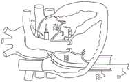
本发明总体上涉及瓣膜修复,并且更具体地涉及对象的房室瓣膜的修复。The present invention relates generally to valve repair, and more particularly to repair of an atrioventricular valve in a subject.
发明背景Background of the Invention
缺血性心脏疾病通过存在于缺血性心脏疾病中的乳头肌缺血性功能异常和左心室扩张的组合以及随后的乳头肌移位和二尖瓣瓣环扩张而引起二尖瓣反流。Ischemic heart disease causes mitral regurgitation through the combination of papillary muscle ischemic dysfunction and left ventricular dilation present in ischemic heart disease with subsequent papillary muscle displacement and mitral valve annular dilatation.
二尖瓣瓣环的扩张阻碍瓣叶在瓣膜闭合时充分接合。血液从左心室到左心房的二尖瓣反流导致总搏出量增加和心输出量减少,以及左心房容量超负荷和压力超负荷继发的最终左心室弱化。Dilation of the mitral valve annulus prevents the leaflets from fully coapting when the valve closes. Mitral regurgitation of blood from the left ventricle to the left atrium results in increased total stroke volume and decreased cardiac output, as well as eventual left ventricular weakening secondary to left atrial volume and pressure overload.
发明内容SUMMARY OF THE INVENTION
在本发明的一些应用中,提供用于访问对象心脏的多部件管状系统。系统包括一个或多个可操纵的引导导管,该引导导管被配置以导向装置通过其中进入心脏。该多部件管状系统被配置以将植入体以期望定向递送至对象的心脏瓣环和促进植入体锚定至瓣环。对于本发明的一些应用,引导系统经腔或经胸推进,访问心脏的心房。一般,系统包括两个或更多个可操纵的导管。第一导管具有远部,该远部可操纵至第一期望空间定向。第二导管被布置在第一导管内,并且具有远部,该远部可操纵至第二期望空间定向。系统提供在不实质上扭转第一导管的远部的第一空间定向的情况下控制第二导管的远部相对于第一导管的定向的技术和相对空间定向控制装置。In some applications of the present invention, a multi-component tubular system for accessing a subject's heart is provided. The system includes one or more steerable guide catheters configured to guide the device therethrough into the heart. The multi-component tubular system is configured to deliver the implant to a subject's heart valve annulus in a desired orientation and to facilitate anchoring of the implant to the annulus. For some applications of the present invention, the guide system is advanced transluminally or transthoracically to access the atria of the heart. Typically, the system includes two or more steerable catheters. The first catheter has a distal portion that is steerable to a first desired spatial orientation. The second catheter is disposed within the first catheter and has a distal portion that is steerable to a second desired spatial orientation. The system provides techniques and relative spatial orientation control means for controlling the orientation of the distal portion of the second catheter relative to the first catheter without substantially twisting the first spatial orientation of the distal portion of the first catheter.
关于一些应用,通过多部件导管系统推进植入体,并且通过利用锚定件驱动器驱动一个或多个组织锚定件穿过通道,将植入体锚定至对象的组织。对于一些应用,锚定件驱动器用于在植入体从导管系统进一步暴露出来时向最近锚定的锚定件提供参考力。对于一些应用,第一组织锚定件具有组织联接元件,该组织联接元件宽于后续锚定件的组织联接元件,并且宽于通道。对于一些应用,矛形件用于控制组织锚定件的锚定。For some applications, the implant is advanced through a multi-component catheter system and anchored to the subject's tissue by driving one or more tissue anchors through the channel with an anchor driver. For some applications, the anchor driver is used to provide a reference force to the most recently anchored anchor as the implant is further exposed from the catheter system. For some applications, the first tissue anchor has tissue-coupling elements that are wider than the tissue-coupling elements of subsequent anchors and wider than the channel. For some applications, spears are used to control the anchoring of the tissue anchors.
对于一些应用,植入体具有收缩构件,该收缩构件自调节机构沿植入体延伸,并再次返回。For some applications, the implant has a constriction member that extends along the implant from the adjustment mechanism and back again.
对于一些应用,提供用于重复对接和调节植入体的调节机构的系统。For some applications, a system is provided for repetitively docking and adjusting the adjustment mechanism of the implant.
对于一些应用,多部件导管系统包括用于测试个体锚定件在其锚定后的锚定强度的测力计。For some applications, the multi-component catheter system includes a dynamometer for testing the anchoring strength of the individual anchors after they are anchored.
还描述了它实施方式。Its implementation is also described.
因此,根据本发明的应用,提供了用于对象组织的设备,该设备包括:Therefore, according to the application of the present invention, there is provided an apparatus for object organization, the apparatus comprising:
锚定件,该锚定件包括:Anchor, the anchor includes:
锚头,和anchor head, and
组织接合构件,该组织接合构件联接至锚头,远离锚头向远侧延伸到组织接合构件的远侧末梢,并且被配置以将锚定件锚定至组织;a tissue engaging member coupled to the anchor head, extending distally away from the anchor head to a distal tip of the tissue engaging member, and configured to anchor the anchor to tissue;
锚定件驱动器,该锚定件驱动器包括:Anchor driver, the anchor driver includes:
纵轴,具有柔性远部和远端,longitudinal axis, with flexible distal and distal ends,
轴远端的部署元件,可以可逆地锁定至锚头和可以可逆地在下列状态之间移动:(i)保持部署元件和锚头之间锁定的锁定状态,和(ii)从锚头解锁部署元件的解锁状态,和A deployment element at the distal end of the shaft, reversibly lockable to the anchor head and reversibly movable between: (i) a locked state that maintains the lock between the deployment element and the anchor head, and (ii) unlocked deployment from the anchor head the unlocked state of the element, and
组织穿刺矛形件,可以可逆地在下列状态之间移动::Tissue piercing lance that can be reversibly moved between:
延伸状态,其中(i)矛形件自轴向远侧延伸,(ii)在部署元件锁定至锚头时,矛形件向远侧延伸越过锚定件的远侧末梢,和(iii)矛形件保持部署元件处于锁定状态,和an extended condition wherein (i) the lance extends distally from the axial direction, (ii) the lance extends distally beyond the distal tip of the anchor when the deployment element is locked to the anchor head, and (iii) the lance extends distally over the distal tip of the anchor shape keeps the deployment element in a locked state, and
收回状态,其中部署元件自动移动至解锁状态。A retracted state in which the deployment element automatically moves to an unlocked state.
在应用中,在收回状态下,矛形件不向远侧延伸越过锚定件的远侧末梢。In use, in the retracted state, the lance does not extend distally beyond the distal tip of the anchor.
在应用中,在收回状态下,矛形件不自轴向远侧延伸。In use, in the retracted state, the lances do not extend distally from the axial direction.
根据本发明的应用,进一步提供了用于对象组织的设备,该设备包括:According to the application of the present invention, there is further provided a device for object organization, the device comprising:
经皮导管;percutaneous catheter;
植入体,被设定尺寸以经由导管被推进到对象中;an implant sized to be advanced into the subject via the catheter;
锚定件递送通道,被塑形以限定其中穿过的腔,该腔具有直径,并且该通道被设定尺寸以可被布置在导管内;an anchor delivery channel shaped to define a lumen therethrough, the lumen having a diameter, and the channel sized to be disposed within the catheter;
至少一个锚定件,包括锚头,该锚头联接至组织联接元件,该锚头限定其中穿过的孔,和at least one anchor including an anchor head coupled to the tissue coupling element, the anchor head defining an aperture therethrough, and
锚定件驱动器:Anchor driver:
包括主干、和联接至主干远端的驱动头,该驱动头可以可逆地联接至锚头,comprising a stem, and a drive head coupled to a distal end of the stem, the drive head being reversibly coupled to the anchor head,
被配置以在驱动头联接至锚头时推进锚定件通过通道的腔,configured to advance the anchor through the lumen of the channel when the drive head is coupled to the anchor head,
进一步包括矛形件,该矛形件可以可逆地相对于驱动头延伸,从而在驱动头联接至锚头时,矛形件的延伸导致矛形件滑动穿过孔,使得矛形件的末梢被布置向远侧越过组织接合元件的远侧末梢,和Further comprising a lance reversibly extendable relative to the drive head such that when the drive head is coupled to the anchor head, the extension of the lance causes the lance to slide through the aperture such that the tip of the lance is disposing distally past the distal tip of the tissue engaging element, and
被配置以驱动矛形件的末梢穿过部分植入体并进入对象的组织,和驱动锚定件的组织联接元件穿过部分植入体并进入对象的组织——独立于矛形件末梢驱动。is configured to drive a tip of the lance through the portion of the implant and into the tissue of the subject, and to drive a tissue coupling element of the anchor through the portion of the implant and into the tissue of the subject - independent of the tip of the lance .
根据本发明的应用,进一步提供了用于对象组织的设备,该设备包括:According to the application of the present invention, there is further provided a device for object organization, the device comprising:
锚定件,包括:Anchors, including:
锚头,具有近侧和远侧,并且限定自近侧至远侧的孔,an anchor head, having proximal and distal sides, and defining a proximal-to-distal hole,
组织接合构件,联接至锚头,远离锚头向远侧延伸到组织接合构件的远侧末梢,并被配置以将锚定件锚定至组织;a tissue engaging member coupled to the anchor head, extending distally away from the anchor head to a distal tip of the tissue engaging member and configured to anchor the anchor to the tissue;
锚定件驱动器,包括:Anchor drive including:
纵轴,具有柔性远部和远端,longitudinal axis, with flexible distal and distal ends,
组织穿刺矛形件,可以自轴向远侧可逆地延伸,Tissue piercing lances, reversibly extendable distally from the axial direction,
部署元件,联接至轴远端,并且在矛形件自轴向远侧的延伸使矛形件移动穿过孔并越过锚定件的远侧末梢的位置处可以可逆地联接至锚头;和a deployment element coupled to the distal end of the shaft and reversibly coupled to the anchor head at a location where extension of the lance from the axially distal side moves the lance through the bore and past the distal tip of the anchor; and
导管系统,包括:Catheter system, including:
导管:catheter:
通过该导管,锚定件驱动器可体内推进——(i)此时部署元件联接至锚头,和(ii)使得轴远部向远侧延伸到导管外,并且Through the catheter, the anchor driver can be advanced in vivo—(i) with the deployment element coupled to the anchor head, and (ii) with the distal shaft extending distally out of the catheter, and
具有远区段,该远区段可相对于远区段近侧紧接的导管的另外区段在体内偏转,和having a distal section that is deflectable in vivo relative to another section of the catheter immediately proximal to the distal section, and
体外控制器,被配置以在轴远部向远侧延伸到导管外以及矛形件自轴向远侧延伸并且被布置在组织中时致使远区段相对于该另外区段偏转,使得轴的远部相对于远部近侧紧接的轴的另外部分偏转,An extracorporeal controller configured to deflect the distal section relative to the additional section when the shaft distal portion extends distally out of the catheter and the lance extends distally from the shaft and is disposed in the tissue such that the shaft The distal portion is deflected relative to the other portion of the shaft immediately proximal to the distal portion,
锚定件驱动器被配置以在轴的远部相对于轴的另外部分偏转时驱动组织接合构件进入组织。The anchor driver is configured to drive the tissue engaging member into tissue when the distal portion of the shaft is deflected relative to the other portion of the shaft.
根据本发明的应用,进一步提供了方法,包括:According to the application of the present invention, a method is further provided, comprising:
推进锚定件驱动的器远端穿过导管和朝向对象组织,锚定件驱动器包括轴、组织穿刺矛形件、和部署元件;advancing the distal end of an anchor-driven actuator through the catheter and toward the subject tissue, the anchor-driven actuator including a shaft, a tissue piercing lance, and a deployment element;
随后,用矛形件穿刺组织;Then, puncture the tissue with a spear;
通过在矛形件中的至少一些被布置在组织内时移动导管的远区段,使轴的远部相对于近侧紧接该远部的轴的另外部分偏转;和deflecting the distal portion of the shaft relative to another portion of the shaft proximally immediately adjacent to the distal portion by moving the distal section of the catheter when at least some of the spears are disposed within the tissue; and
在(i)轴的远部相对于轴的另外部分偏转,以及(ii)部署元件锁定至锚定件头部时,利用锚定件驱动器驱动锚定件的组织接合构件进入组织。When (i) the distal portion of the shaft is deflected relative to the other portion of the shaft, and (ii) the deployment element is locked to the anchor head, the anchor driver is used to drive the tissue engaging member of the anchor into the tissue.
根据本发明的应用,进一步提供了用于植入体的方法,方法包括:According to the application of the present invention, there is further provided a method for an implant, the method comprising:
利用联接至植入体的植入体操纵柄经皮将植入体朝向对象的植入位点穿过导管推进;percutaneously advancing the implant through the catheter toward the implant site of the subject using an implant handle coupled to the implant;
通过施加第一力至植入体操纵柄,使植入体相对于导管滑动,而不导致植入体施力至植入位点处的组织;sliding the implant relative to the catheter without causing the implant to apply force to tissue at the implant site by applying a first force to the implant handle;
测量第一力的量级;measure the magnitude of the first force;
随后,锚定植入体至植入位点处的组织;then, anchoring the implant to the tissue at the implantation site;
随后,通过施加第二力至植入体操纵柄,致使植入体经由植入体的锚定施加第三力至植入位点处的组织;then causing the implant to apply a third force to tissue at the implant site via anchoring of the implant by applying a second force to the implant handle;
测量第二力的量级;和measure the magnitude of the second force; and
至少部分响应第一力量级和第二力量级之差,确定第三力的量级。The magnitude of the third force is determined at least in part in response to the difference between the first force level and the second force level.
在应用中,通过施加第一力至植入体操纵柄使植入体滑动包括,通过施加第一力至植入体操纵柄,使植入体相对于导管向近侧滑动。In use, sliding the implant by applying the first force to the implant handle includes sliding the implant proximally relative to the catheter by applying the first force to the implant handle.
在应用中:In the application:
测量第一力的量级包括利用测力计测量第一力的量级,Measuring the magnitude of the first force includes measuring the magnitude of the first force with a dynamometer,
测量第二力的量级包括利用测力计测量第二力的量级,和Measuring the magnitude of the second force includes measuring the magnitude of the second force with a dynamometer, and
方法进一步包括,在测量第一力的量级后和致使植入体施加第三力前,将测力计零位调整至第一力的量级。The method further includes, after measuring the magnitude of the first force and before causing the implant to apply the third force, zeroing the dynamometer to the magnitude of the first force.
在应用中:In the application:
锚定件操纵柄包括测力计,The anchor handle includes a dynamometer,
测量第一力的量级包括利用测力计测量第一力的量级,和measuring the magnitude of the first force includes measuring the magnitude of the first force with a dynamometer, and
测量第二力的量级包括利用测力计测量第二力的量级。Measuring the magnitude of the second force includes measuring the magnitude of the second force with a dynamometer.
在应用中,锚定植入体包括,通过将组织锚定件驱动到植入位点处的组织中,来锚定植入体。In application, anchoring the implant includes anchoring the implant by driving tissue anchors into tissue at the implantation site.
在应用中,通过施加第二力至植入体操纵柄致使植入体施加第三力包括,通过施加第二力至植入体操纵柄,致使植入体经由组织锚定件而施加第三力。In application, causing the implant to apply the third force by applying the second force to the implant handle includes causing the implant to apply the third force via the tissue anchor by applying the second force to the implant handle force.
根据本发明的应用,进一步提供了设备,包括:According to the application of the present invention, equipment is further provided, including:
可经皮植入的植入体;percutaneously implantable implants;
调节装置,包括:Adjustment device, including:
调节机构,联接至植入体,并且被配置以在调节机构致动后改变植入体的尺寸;和an adjustment mechanism coupled to the implant and configured to change the size of the implant upon actuation of the adjustment mechanism; and
锁:Lock:
具有锁定状态,其中锁抑制调节机构致动,has a locked state in which the lock inhibits actuation of the adjustment mechanism,
具有解锁状态,其中调节机构是可致动的,并且has an unlocked state in which the adjustment mechanism is actuatable, and
可以可逆地在锁定状态和解锁状态之间移动;Can be reversibly moved between locked and unlocked states;
纵向引导构件;和longitudinal guide members; and
接头:Connector:
联接至引导构件,coupled to the guide member,
包括使接头联接至调节装置的紧固件,并且可在体内从调节装置解联(decouplable),comprising a fastener that couples the joint to the adjustment device and is decouplable from the adjustment device in vivo,
被配置以在联接至调节装置时被经皮递送,并且is configured to be delivered transdermally when coupled to the adjustment device, and
包括解锁机构,该解锁机构被配置使得,在接头联接至调节装置时,解锁机构的致动使锁在锁定状态和解锁状态之间移动。An unlocking mechanism is included that is configured such that actuation of the unlocking mechanism moves the lock between a locked state and an unlocked state when the joint is coupled to the adjustment device.
在应用中,解锁机构的致动,通过解锁机构按压在锁的可按压部分上,使锁从锁定状态移动至解锁状态。In application, actuation of the unlocking mechanism, by the unlocking mechanism pressing on the depressible portion of the lock, moves the lock from the locked state to the unlocked state.
在应用中,解锁机构包括布置在通道中的销,并且使锁从锁定状态移动至解锁状态的解锁机构致动包括销在通道内滑动。In application, the unlocking mechanism includes a pin disposed in the channel, and actuation of the unlocking mechanism to move the lock from the locked state to the unlocked state includes sliding the pin within the channel.
在应用中,紧固件被塑形以限定至少部分通道。In application, the fastener is shaped to define at least a portion of the channel.
在应用中:In the application:
调节装置被塑形以限定第一螺纹,和the adjustment device is shaped to define the first thread, and
紧固件(i)被塑形以限定第二螺纹,该第二螺纹使紧固件通过啮合第一螺纹而联接至调节装置,并且(ii)通过第二螺纹从第一螺纹解旋,可在体内从调节装置解联。The fastener is (i) shaped to define a second thread that couples the fastener to the adjustment device by engaging the first thread, and (ii) unscrewed from the first thread by the second thread, which can be Uncoupling from regulatory devices in vivo.
在应用中,锁在不存在可按压部分的按压时被偏置处于锁定状态。In application, the lock is biased in the locked state in the absence of depression of the depressible portion.
在应用中,设备进一步包括调节工具,并且该调节工具:In applications, the device further includes an adjustment tool, and the adjustment tool:
在植入植入体后可沿引导构件经皮推进至接头,After implantation of the implant, it can be advanced percutaneously along the guide member to the joint,
包括调节机构接口,该调节机构接口被设定尺寸以交接调节机构,including an adjustment mechanism interface sized to interface with the adjustment mechanism,
包括接头接口,该接头接口被设定尺寸以交接接头,并且包括施力装置,并且includes a splice interface dimensioned to interface the splice, and includes a force applying device, and
被配置以:is configured with:
使锁移动至解锁状态——通过在接头联接至调节装置时,通过以施力装置施力至解锁机构而致动解锁机构,和moving the lock to the unlocked state - by actuating the unlocking mechanism by applying force to the unlocking mechanism with a force-applying device when the joint is coupled to the adjustment device, and
经由调节机构接口和调节机构之间的接驳,致动调节机构。The adjustment mechanism is actuated via the interface between the adjustment mechanism interface and the adjustment mechanism.
在应用中,工具被配置以从调节装置解联接头。In application, the tool is configured to uncouple the joint from the adjustment device.
在应用中,调节机构接口和接头接口是可独立控制的。In application, the adjustment mechanism interface and the joint interface are independently controllable.
在应用中,工具被配置以独立于致动解锁机构从调节装置解联接头。In application, the tool is configured to uncouple the joint from the adjustment device independently of actuating the unlocking mechanism.
在应用中,施力装置相对于接头可轴向滑动的,并且被配置以通过施加轴向力至解锁机构而致动解锁机构。In application, the force applying device is axially slidable relative to the joint and is configured to actuate the unlocking mechanism by applying an axial force to the unlocking mechanism.
在应用中:In the application:
接头包括主体,该主体被塑形以限定通道,The fitting includes a body shaped to define a channel,
解锁机构包括通道、和在通道内布置并且可滑动的销,以及the unlocking mechanism includes a channel, and a pin disposed within the channel and slidable, and
施力装置被配置以致动解锁机构——通过施加轴向力至销而使销在通道内滑动。The force application device is configured to actuate the unlocking mechanism by applying an axial force to the pin to slide the pin within the channel.
在应用中,主体被塑形以限定侧面开口,销包括从开口向侧面突出的附件,并且接头接口被设定尺寸以便在主体近部上可滑动,其程度足够使得施力装置到达附件。In application, the body is shaped to define a side opening, the pin includes an appendage projecting sideways from the opening, and the joint interface is sized to be slidable over the proximal portion of the body to a degree sufficient for the force application device to reach the appendage.
在应用中,主体近部的横截面具有非圆形的外部形状,并且工具被配置以通过经由接头接口施加扭矩至主体,从调节装置解联接头。In application, the cross-section of the proximal portion of the body has a non-circular outer shape, and the tool is configured to decouple the joint from the adjustment device by applying torque to the body via the joint interface.
在应用中,接头接口的远部成角(angled),使得响应接头接口在主体近部上的轴向滑动,接头接口自动呈现相对于主体的预定旋转定向。In application, the distal portion of the joint interface is angled such that in response to axial sliding of the joint interface over the proximal portion of the body, the joint interface automatically assumes a predetermined rotational orientation relative to the body.
在应用中,接头接口的远部成角,使得在预定旋转定向下,施力装置与附件对齐。In application, the distal portion of the connector interface is angled so that in a predetermined rotational orientation, the force application device is aligned with the accessory.
在应用中,施力装置成角,使得响应接头接口在主体近部上的轴向滑动,接头接口自动呈现相对于主体的预定旋转定向。In application, the force-applying device is angled such that in response to axial sliding of the joint interface over the proximal portion of the body, the joint interface automatically assumes a predetermined rotational orientation relative to the body.
在应用中,接头接口的远部成角,使得在预定旋转定向下,施力装置与附件对齐。In application, the distal portion of the connector interface is angled so that in a predetermined rotational orientation, the force application device is aligned with the accessory.
在应用中,在接头接口呈现其中施力装置与附件对齐的预定旋转定向时,主体近部的非圆形形状抑制接头接口响应接头接口在主体上的轴向进一步滑动而进一步旋转。In application, the non-circular shape of the proximal portion of the body inhibits further rotation of the joint interface in response to further axial sliding of the joint interface on the body when the joint interface assumes a predetermined rotational orientation in which the force-applying device is aligned with the accessory.
在应用中,主体被塑形以限定一个或多个凸肩,该凸肩成角,使得响应接头接口在凸肩上的轴向滑动,接头接口自动呈现相对于主体的预定旋转定向。In application, the body is shaped to define one or more shoulders that are angled such that in response to axial sliding of the joint interface over the shoulders, the joint interface automatically assumes a predetermined rotational orientation relative to the body.
在应用中,接头接口的远部成角,使得在预定旋转定向下,施力装置与附件对齐。In application, the distal portion of the connector interface is angled so that in a predetermined rotational orientation, the force application device is aligned with the accessory.
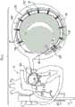
根据本发明的应用,进一步提供了用于对象组织的设备,该设备包括瓣膜成形结构,该瓣膜成形结构包括:According to applications of the present invention, there is further provided a device for subject tissue, the device comprising a valvuloplasty structure, the valvuloplasty structure comprising:
套筒,具有第一端和第二端、轴承位点,并且包括侧壁,该侧壁限定自第一端至第二端的腔,a sleeve having first and second ends, a bearing site, and including a sidewall defining a cavity from the first end to the second end,
调节机构,和Regulators, and
收缩构件:Shrink member:
具有联接至调节机构的第一端,having a first end coupled to the adjustment mechanism,
具有自调节机构沿套筒朝向第二端延伸直到轴承位点的第一部分,以及a first portion having a self-adjusting mechanism extending along the sleeve toward the second end up to the bearing site, and
具有自轴承位点返向调节机构和第一端延伸的第二部分,having a second portion extending from the bearing site back adjustment mechanism and the first end,
调节机构被配置以在收缩构件的第一部分上进行牵拉使得收缩构件的第二部分渐进地滑过轴承位点,来减少第一端和第二端之间的套筒长度。The adjustment mechanism is configured to pull on the first portion of the retraction member such that the second portion of the retraction member progressively slides past the bearing site to reduce the sleeve length between the first and second ends.
在应用中,第一部分交织穿过套筒的侧壁。In application, the first portion is interwoven through the sidewall of the sleeve.
在应用中,第二部分交织穿过套筒的侧壁。In application, the second portion is interwoven through the sidewall of the sleeve.
在应用中,第一部分沿腔通过(pass)。In application, the first portion passes along the cavity.
在应用中,第二部分沿腔通过。In application, the second portion passes along the cavity.
在应用中,收缩构件具有第二端,该第二端柔性联接至套筒。In application, the shrink member has a second end that is flexibly coupled to the sleeve.
在应用中,套筒中具有孔穴,该孔穴限定轴承位点,收缩构件可穿过孔穴滑动。In application, the sleeve has a cavity therein which defines a bearing site through which the constriction member can slide.
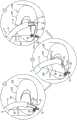
根据本发明的应用,进一步提供了方法,包括:According to the application of the present invention, a method is further provided, comprising:
在锚定件递送通道的远部被布置在腔内时,将包括限定管状侧壁和腔的套筒的植入体朝向对象的组织经皮推进,使得通道的远侧开口布置在套筒的第一部分处;With the distal portion of the anchor delivery channel disposed within the lumen, the implant including the sleeve defining the tubular sidewall and the lumen is advanced percutaneously toward the subject's tissue such that the distal opening of the channel is disposed in the sleeve's distal end. at the first part;
锚定套筒的第一部分至第一组织位点——通过利用锚定件驱动器驱动第一锚定件的组织联接元件穿过通道的远侧开口,穿过套筒第一部分的侧壁,并进入第一组织位点;anchoring the first portion of the sleeve to the first tissue site by driving the tissue-coupling element of the first anchor through the distal opening of the channel, through the sidewall of the first portion of the sleeve with the anchor driver, and access to the first tissue site;
向第二组织位点按压套筒的第二部分;和pressing the second portion of the sleeve toward the second tissue site; and
将套筒的第二部分锚定至第二组织位点——通过驱动第二锚定件的组织联接元件自腔外穿过套筒第二部分侧壁的相对侧,并进入第二组织位点。Anchoring the second portion of the sleeve to the second tissue site by actuating the tissue coupling element of the second anchor extraluminally through the opposite side of the sidewall of the second portion of the sleeve and into the second tissue site point.
在应用中,向第二组织位点按压套筒的第二部分包括向第二组织位点按压套筒的第二部分,使得套筒第二部分侧壁的相对侧彼此接触。In application, pressing the second portion of the sleeve against the second tissue site includes pressing the second portion of the sleeve against the second tissue site such that opposing sides of sidewalls of the second portion of the sleeve contact each other.
在应用中:In the application:
植入体包括瓣膜成形结构,该瓣膜成形结构包括套筒,The implant includes a valvuloplasty structure including a sleeve,
将套筒的第一部分锚定至第一组织位点包括将套筒的第一部分锚定至对象心脏的房室瓣膜瓣环,和Anchoring the first portion of the sleeve to the first tissue site includes anchoring the first portion of the sleeve to an atrioventricular valve annulus of the subject's heart, and
将套筒的第二部分锚定至第二组织位点包括将套筒的第二部分锚定至对象心脏的心房壁。Anchoring the second portion of the sleeve to the second tissue site includes anchoring the second portion of the sleeve to an atrial wall of the subject's heart.
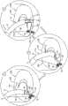
根据本发明的应用,进一步提供了方法,该方法包括:According to the application of the present invention, a method is further provided, the method comprising:
在锚定件递送通道的远部布置在套筒限定的腔内时,朝向对象的组织经皮推进包括套筒的植入体,使得通道的远侧开口布置在套筒的第一部分处;with the distal portion of the anchor delivery channel disposed within the lumen defined by the sleeve, percutaneously advancing the implant including the sleeve toward the tissue of the subject such that the distal opening of the channel is disposed at the first portion of the sleeve;
将套筒的第一部分锚定至组织——通过利用锚定件驱动器驱动第一锚定件的组织联接元件穿过通道的远侧开口,穿过套筒,并进入组织;anchoring the first portion of the sleeve to the tissue by driving the tissue coupling element of the first anchor through the distal opening of the channel, through the sleeve, and into the tissue with the anchor driver;
随后,在通过驱动器提供远侧方向的参考力至第一锚定件时,向近侧撤回通道的远部,使得通道的远侧开口布置在套筒的第二部分处;then, while providing a distally directed reference force to the first anchor by the driver, withdrawing the distal portion of the channel proximally such that the distal opening of the channel is disposed at the second portion of the sleeve;
随后,使驱动器通过通道向近侧撤回;和Subsequently, the driver is withdrawn proximally through the channel; and
随后,将套筒的第二部分锚定至组织——通过驱动第二锚定件的组织联接元件穿过通道的远侧开口,穿过套筒,并进入组织。Subsequently, the second portion of the sleeve is anchored to the tissue by driving the tissue coupling element of the second anchor through the distal opening of the channel, through the sleeve, and into the tissue.
根据本发明的应用,进一步提供了用于对象组织的设备,该设备包括:According to the application of the present invention, there is further provided a device for object organization, the device comprising:
经皮导管;percutaneous catheter;
植入体,被设定尺寸以经由导管被推进到对象中;an implant sized to be advanced into the subject via the catheter;
锚定件递送通道,被塑形以限定其中穿过的腔,该腔具有直径,并且该通道被设定尺寸以可布置在导管内;an anchor delivery channel shaped to define a lumen therethrough, the lumen having a diameter, and the channel sized to be disposed within the catheter;
至少一个小锚定件,其包括联接至小锚定件组织联接元件的小锚定件锚头,并且具有自小锚定件锚头至小锚定件组织联接元件的中心纵轴,小锚定件的最大横向宽度小于通道腔的直径;At least one small anchor comprising a small anchor head coupled to a small anchor tissue coupling element and having a central longitudinal axis from the small anchor head to the small anchor tissue coupling element, the small anchor The maximum lateral width of the stator is less than the diameter of the channel cavity;
至少一个大锚定件,其包括联接至大锚定件组织联接元件的大锚定件锚头,并且具有自大锚定件锚头至大锚定件组织联接元件的中心纵轴,大锚定件的最大横向宽度大于通道腔的直径;和at least one large anchor comprising a large anchor head coupled to the large anchor tissue coupling element and having a central longitudinal axis from the large anchor head to the large anchor tissue coupling element, the large anchor the maximum lateral width of the stator is greater than the diameter of the channel cavity; and
锚定件驱动器,包括可以可逆地联接至大锚定件锚头的驱动头、和主干,该主干被设定尺寸以在驱动头联接至大锚定件锚头时自驱动头穿过通道腔延伸到通道近端外。Anchor driver including a drive head reversibly coupleable to a large anchor head, and a stem sized to pass from the drive head through a channel lumen when the drive head is coupled to the large anchor head Extend beyond the proximal end of the channel.
在应用中:In the application:
大锚定件被布置在通道的远部,并且至少大锚定件组织联接元件在通道腔外,the large anchor is disposed at the distal portion of the channel, and at least the large anchor tissue coupling element is outside the lumen of the channel,
驱动头联接至大锚定件锚头,The drive head is coupled to the large anchor anchor head,
主干自驱动头向近侧穿过通道腔延伸到通道近端外,The trunk extends proximally from the drive head through the channel lumen to the outside of the proximal end of the channel,
植入体被塑形以限定腔,The implant is shaped to define the cavity,
通道远部和大锚定件组织联接元件被布置在植入体的腔内,并且在处于植入体腔内时可随植入体穿过导管滑动。The distal portion of the channel and the large anchor tissue coupling element are disposed within the lumen of the implant and are slidable through the catheter with the implant while in the lumen of the implant.
在应用中,通道腔的直径为2-3mm。In application, the diameter of the channel cavity is 2-3 mm.
在应用中,大锚定件的最大横向宽度为3-4mm。In application, the maximum lateral width of the large anchor is 3-4mm.
在应用中,大锚定件组织接合元件被塑形以限定具有3-4mm横向宽度的螺旋。In application, the large anchor tissue engaging elements are shaped to define a helix having a lateral width of 3-4 mm.
在应用中,大锚定件锚头具有2-3mm的最大横向宽度。In application, the large anchor head has a maximum lateral width of 2-3mm.
在应用中,小锚定件组织接合元件被塑形以限定具有2-3mm横向宽度的螺旋。In application, the small anchor tissue engaging elements are shaped to define a helix having a lateral width of 2-3 mm.
在应用中,大锚定件的最大横向宽度是大锚定件组织联接元件的最大横向宽度。In application, the maximum lateral width of the large anchor is the maximum lateral width of the tissue coupling element of the large anchor.
在应用中,大锚定件锚头的最大横向宽度小于通道腔的直径。In application, the maximum lateral width of the large anchor head is less than the diameter of the channel lumen.
在应用中,大锚定件锚头的最大横向宽度大于通道腔的直径。In application, the maximum lateral width of the large anchor head is greater than the diameter of the channel lumen.
根据本发明的一些应用,另外提供了植入体,该植入体具有主体部分,该植入体包括:According to some applications of the present invention, there is additionally provided an implant having a body portion, the implant comprising:
收缩构件;shrink member;
可致动的调节机构,其联接至收缩构件,并且被配置以在被致动时通过施加张力至收缩构件来调节植入体的主体部分的尺寸;和an actuatable adjustment mechanism coupled to the constriction member and configured to adjust the size of the body portion of the implant by applying tension to the constriction member when actuated; and
调节指示器,其联接至收缩构件并且直接联接至植入体的主体部分,并且被配置以根据收缩构件的张力程度来改变形状。An adjustment indicator is coupled to the collapsible member and directly to the body portion of the implant, and is configured to change shape according to the degree of tension of the collapsible member.
在本发明的一些应用中,植入体包括瓣膜成形环结构。In some applications of the present invention, the implant includes an annuloplasty ring structure.
在本发明的一些应用中,主体部分包括套筒。In some applications of the invention, the body portion includes a sleeve.
在本发明的一些应用中,调节指示器直接联接至植入体主体部分的外表面。In some applications of the present invention, the adjustment indicator is coupled directly to the outer surface of the implant body portion.
在本发明的一些应用中,调节指示器包括射线不透性元件。In some applications of the invention, the adjustment indicator includes a radiopaque element.
在本发明的一些应用中,植入体包括瓣膜成形结构,并且收缩构件经由射线不透性元件联接至瓣膜成形结构。In some applications of the present invention, the implant includes a valvuloplasty structure, and the collapsible member is coupled to the valvuloplasty structure via a radiopaque element.
在本发明的一些应用中:In some applications of the present invention:
射线不透性元件包括:Radiopaque elements include:
容器;和container; and
塞子,其被塑形以适配在容器内,a stopper, which is shaped to fit within the container,
收缩构件通过联接至塞子而联接至射线不透性元件,使得收缩构件的张力程度的增加通过在容器内定位塞子而使射线不透性元件的形状改变。The collapsible member is coupled to the radiopaque element by being coupled to the stopper, such that an increase in the degree of tension of the collapsible member changes the shape of the radiopaque element by positioning the stopper within the container.
在本发明的一些应用中,射线不透性元件被布置与调节机构相邻。In some applications of the present invention, the radiopaque element is disposed adjacent to the adjustment mechanism.
在本发明的一些应用中,调节机构在收缩构件的第一端部处联接至收缩构件,并且射线不透性元件在收缩构件的第二端部处联接至收缩构件。In some applications of the invention, the adjustment mechanism is coupled to the constriction member at a first end of the constriction member, and the radiopaque element is coupled to the constriction member at a second end of the constriction member.
在本发明的一些应用中,收缩构件穿过(threaded through)射线不透性元件。In some applications of the present invention, the constriction member is threaded through the radiopaque element.
在本发明的一些应用中,植入体包括瓣膜成形结构,并且射线不透性元件联接至收缩构件,使得收缩构件的张力程度的增加通过将射线不透性元件按压在瓣膜成形结构上而使射线不透性元件的形状改变。In some applications of the present invention, the implant includes a valvuloplasty structure, and the radiopaque element is coupled to the collapsible member such that an increase in the degree of tension of the collapsible member is caused by pressing the radiopaque element against the valvuloplasty structure The shape of the radiopaque element changes.
在本发明的一些应用中,射线不透性元件包括带。In some applications of the present invention, the radiopaque element includes a tape.
在本发明的一些应用中,该带具有1-3mm的宽度。In some applications of the present invention, the belt has a width of 1-3 mm.
在本发明的一些应用中:In some applications of the present invention:
在张力未施加至收缩构件时,处于未受压状态的带的形状具有沿带纵轴测量的4-6mm的未受压纵向长度,和The shape of the belt in the uncompressed state has an uncompressed longitudinal length of 4-6 mm measured along the longitudinal axis of the belt when tension is not applied to the constricting member, and
响应收缩构件的张力程度的增加,至少部分带被压向植入体,呈现受压状态,并且具有沿带纵轴测量的7-10mm的受压纵向长度。In response to an increase in the degree of tension of the constricting member, at least a portion of the band is compressed toward the implant, assumes a compressed state, and has a compressed longitudinal length of 7-10 mm measured along the longitudinal axis of the band.
在本发明的一些应用中,射线不透性元件包括围绕部分收缩构件的管。In some applications of the present invention, the radiopaque element includes a tube surrounding a portion of the constriction member.
在本发明的一些应用中,射线不透性元件联接至收缩构件,使得收缩构件的张力程度的增加通过使管压缩而使射线不透性元件的形状改变。In some applications of the present invention, the radiopaque element is coupled to the constricting member such that an increase in the degree of tension of the constricting member changes the shape of the radiopaque element by compressing the tube.
在本发明的一些应用中,射线不透性元件包括弹簧。In some applications of the present invention, the radiopaque element includes a spring.
在本发明的一些应用中,射线不透性元件联接至收缩构件,使得收缩构件的张力程度的增加通过扩张弹簧而使射线不透性元件的形状改变。In some applications of the present invention, the radiopaque element is coupled to the collapsible member such that an increase in the degree of tension of the collapsible member changes the shape of the radiopaque element through the expansion spring.
在本发明的一些应用中,弹簧包括截锥涡卷弹簧。In some applications of the present invention, the spring comprises a truncated cone scroll spring.
在本发明的一些应用中,弹簧包括围绕部分收缩构件的伸缩式弹簧。In some applications of the present invention, the spring includes a telescoping spring surrounding a portion of the retracting member.
在本发明的一些应用中,射线不透性元件联接至收缩构件,使得收缩构件的张力程度的增加通过压缩弹簧而使射线不透性元件的形状改变。In some applications of the present invention, the radiopaque element is coupled to the constricting member such that an increase in the degree of tension of the constricting member changes the shape of the radiopaque element by compressing the spring.
在本发明的一些应用中:In some applications of the present invention:
射线不透性元件被塑形以限定至少第一和第二臂,以及the radiopaque element is shaped to define at least the first and second arms, and
收缩构件通过联接至第一和第二臂中的每一个而联接至射线不透性元件,使得收缩构件的张力程度的增加通过改变第一和第二臂之间的距离而使射线不透性元件的形状改变。The constricting member is coupled to the radiopaque element by being coupled to each of the first and second arms such that an increase in the degree of tension of the constricting member renders the radiopaque by changing the distance between the first and second arms The shape of the element changes.
在本发明的一些应用中,响应收缩构件的张力程度的增加,第一和第二臂被相向牵引。In some applications of the present invention, the first and second arms are drawn toward each other in response to an increase in the degree of tension of the retractable member.
在本发明的一些应用中,收缩构件穿过第一和第二臂的对应部分。In some applications of the present invention, the constriction member passes through corresponding portions of the first and second arms.
根据本发明的一些应用还另外提供了植入体,该植入体包括:According to some applications of the present invention there is additionally provided an implant comprising:
瓣膜成形结构,其具有基本主体部分(primary body portion);a valvuloplasty structure having a primary body portion;
收缩构件,至少沿瓣膜成形结构的收缩部分延伸;a constricted member extending at least along the constricted portion of the valvuloplasty structure;
可致动的调节机构,其联接至收缩构件,并且被配置以在被致动时通过施加张力至收缩构件来调节瓣膜成形结构的长度;和an actuatable adjustment mechanism coupled to the collapsed member and configured to adjust the length of the valvuloplasty structure by applying tension to the collapsed member when actuated; and
收缩构件保护元件,其具有联接至瓣膜成形结构的基本主体部分的第一端、和联接至调节机构的第二端,a collapsed member protection element having a first end coupled to the base body portion of the valvuloplasty structure, and a second end coupled to the adjustment mechanism,
收缩构件自调节机构经由收缩构件保护元件延伸至瓣膜成形结构的基本主体部分。The collapse member self-adjusting mechanism extends to the substantial body portion of the valvuloplasty structure via the collapse member protection element.
在本发明的一些应用中,收缩构件保护元件的第一端在距瓣膜成形结构任意端至少10mm的连接点处连接至瓣膜成形结构。In some applications of the present invention, the first end of the collapsible member protection element is connected to the valvuloplasty structure at a connection point at least 10 mm from either end of the valvuloplasty structure.
在本发明的一些应用中,瓣膜成形结构包括第一套筒,该第一套筒包括限定穿过第一套筒的第一腔的管状侧壁,收缩构件保护元件包括第二套筒,该第二套筒限定穿过第二套筒的第二腔,并且部分收缩构件被布置在第二腔内。In some applications of the present invention, the valvuloplasty structure includes a first sleeve including a tubular sidewall defining a first lumen through the first sleeve, the collapsible member protection element includes a second sleeve, the The second sleeve defines a second cavity therethrough, and a portion of the constriction member is disposed within the second cavity.
在本发明的一些应用中,收缩构件保护元件包括带,并且收缩构件穿过该带。In some applications of the present invention, the shrink member protection element includes a strap, and the shrink member passes through the strap.
在本发明的一些应用中,该带具有3-5mm的宽度。In some applications of the present invention, the belt has a width of 3-5mm.
在本发明的一些应用中,该带的带宽10倍大于收缩构件的宽度。In some applications of the present invention, the belt width is 10 times greater than the width of the shrink member.
在本发明的一些应用中,收缩构件保护元件包括弹簧,并且收缩构件被布置在弹簧的腔内。In some applications of the present invention, the retraction member protection element includes a spring, and the retraction member is disposed within a cavity of the spring.
在本发明的一些应用中:In some applications of the present invention:
收缩构件保护元件的第一端在连接点处连接至瓣膜成形结构,the first end of the collapsed member protection element is connected to the valvuloplasty structure at the connection point,
瓣膜成形结构限定中心纵轴,The valvuloplasty structure defines a central longitudinal axis,
植入体具有递送状态,其中:The implant has a delivery state where:
植入体可穿过导管经皮推进至植入位点,并且The implant can be advanced percutaneously through the catheter to the implantation site, and
调节机构被布置在中心纵轴上,瓣膜成形结构的远侧,并且收缩构件保护元件自连接点与瓣膜成形结构并排延伸至调节机构,the adjustment mechanism is disposed on the central longitudinal axis, distal to the valvuloplasty structure, and the retraction member protection element extends from the attachment point alongside the valvuloplasty structure to the adjustment mechanism,
植入体具有部署状态,其中:The implant has a deployed state where:
调节机构被布置在中心纵轴的侧面,并且The adjustment mechanism is arranged on the side of the central longitudinal axis, and
通过调节机构进行的收缩构件的张拉使调节机构移动更接近连接点,并且压缩收缩构件保护元件。The tensioning of the contraction member by the adjustment mechanism moves the adjustment mechanism closer to the connection point and compresses the contraction member protection element.
在本发明的一些应用中,在沿收缩构件保护元件的中心纵轴测量时,收缩构件保护元件在张拉收缩构件前具有10-15mm的纵向长度。In some applications of the present invention, the shrink member protection element has a longitudinal length of 10-15 mm before tensioning the shrink member when measured along the central longitudinal axis of the shrink member protection element.
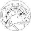
在本发明的一些应用中,设备进一步包括多个组织锚定件:In some applications of the present invention, the device further comprises a plurality of tissue anchors:
瓣膜成形结构具有远端、和在连接点和远端之间延伸的远部,The valvuloplasty structure has a distal end, and a distal portion extending between the attachment point and the distal end,
多个组织锚定件包括(i)布置在瓣膜成形结构的远部的至少三个组织锚定件,和(ii)布置在瓣膜成形结构的收缩部分的至少一个组织锚定件。The plurality of tissue anchors include (i) at least three tissue anchors disposed in the distal portion of the valvuloplasty structure, and (ii) at least one tissue anchor member disposed in the collapsed portion of the valvuloplasty structure.
根据本发明的一些应用,进一步提供了包括植入体的设备,该植入体包括:According to some applications of the present invention, there is further provided a device comprising an implant comprising:
瓣膜成形结构,其包括第一套筒,该第一套筒包括限定穿过第一套筒的第一腔的管状侧壁;a valvuloplasty structure including a first sleeve including a tubular sidewall defining a first lumen through the first sleeve;
收缩构件,其具有至少沿瓣膜成形结构的第一套筒的收缩部分延伸的第一部分,收缩构件在第一腔的出口点处离开第一腔;a collapsed member having a first portion extending at least along a collapsed portion of the first sleeve of the valvuloplasty structure, the collapsed member exiting the first lumen at an exit point of the first lumen;
可致动的调节机构,其在收缩构件的端部联接至收缩构件,并且被配置以在被致动时通过施加张力至收缩构件来调节瓣膜成形结构的长度;和an actuatable adjustment mechanism coupled to the collapsed member at an end of the collapsed member and configured to adjust the length of the valvuloplasty structure by applying tension to the collapsed member when actuated; and
第二套筒,其在收缩构件自第一腔的出口点处联接至第一套筒,第二套筒:A second sleeve coupled to the first sleeve at the point of exit of the constriction member from the first cavity, the second sleeve:
限定穿过第二套筒的第二腔,收缩构件的第二部分被布置在第二腔内并且延伸至调节机构,以及a second cavity is defined through the second sleeve, the second portion of the constriction member is disposed within the second cavity and extends to the adjustment mechanism, and
联接调节机构至第一套筒。The adjustment mechanism is coupled to the first sleeve.
根据本发明的一些应用,还进一步提供了用于对象的设备,该设备包括:According to some applications of the present invention, there is further provided an apparatus for an object, the apparatus comprising:
可经腔推进到对象中的导管;和A catheter that can be advanced transluminally into a subject; and
可穿过导管推进的植入体,该植入体包括柔性套筒,该柔性套筒限定腔,具有近端、远端和其间的中心纵轴,该植入体在套筒绕套筒纵轴扭转时绕套筒纵轴扭转并且可穿过导管纵向滑动。An implant advanceable through a catheter comprising a flexible sleeve defining a lumen having a proximal end, a distal end and a central longitudinal axis therebetween, the implant extending longitudinally around the sleeve at the sleeve When the shaft is twisted, it twists about the longitudinal axis of the sleeve and can slide longitudinally through the catheter.
在本发明的一些应用中,套筒近端和远端之间的扭转角度为170-190度。In some applications of the present invention, the angle of twist between the proximal and distal ends of the sleeve is 170-190 degrees.
在本发明的一些应用中,设备进一步包括穿过导管可纵向滑动的通道,植入体的柔性套筒在套筒绕套筒轴扭转时包覆通道远部,并且在套筒绕套筒轴扭转时套筒包覆通道远部的时候,植入体随通道穿过导管可纵向滑动。In some applications of the invention, the device further includes a longitudinally slidable channel through the catheter, the flexible sleeve of the implant wraps the distal portion of the channel when the sleeve is twisted about the quill, and when the sleeve is twisted about the quill When the sleeve wraps the distal portion of the channel when twisted, the implant can slide longitudinally with the channel through the catheter.
在本发明的一些应用中,设备进一步包括:In some applications of the present invention, the device further comprises:
沿套筒纵向延伸的收缩构件;和a retraction member extending longitudinally of the sleeve; and
可致动的调节机构,其联接至收缩构件,并且被配置以在被致动时通过施加张力至收缩构件来调节植入体的尺寸。An actuatable adjustment mechanism coupled to the constricting member and configured to adjust the size of the implant by applying tension to the constricting member when actuated.
在本发明的一些应用中,收缩构件具有联接至调节机构的第一端部、和联接至植入体套筒的第二端部,在套筒绕套筒轴扭转时,调节机构以155和175度之间的扭转角度自收缩构件的第二端部扭转。In some applications of the present invention, the collapsible member has a first end coupled to an adjustment mechanism, and a second end coupled to the implant sleeve, the adjustment mechanism at 155 and 155 when the sleeve is twisted about the quill A twist angle of between 175 degrees twists from the second end of the retracting member.
在本发明的一些应用中,设备进一步包括穿过导管可纵向滑动的通道,植入体的柔性套筒在绕套筒轴扭转时包覆通道的远部,并且在套筒绕套筒轴扭转时包覆通道的远部的时候,植入体随通道穿过导管可纵向滑动。In some applications of the present invention, the device further comprises a longitudinally slidable channel through the catheter, the flexible sleeve of the implant wraps the distal portion of the channel when twisted about the quill, and when the sleeve is twisted about the quill When covering the distal portion of the channel, the implant can slide longitudinally with the channel through the catheter.
在本发明的一些应用中,在套筒在绕套筒轴扭转时包覆通道远部的时候,植入体围绕通道的中心纵轴旋转。In some applications of the present invention, the implant rotates about the central longitudinal axis of the channel as the sleeve wraps the distal portion of the channel when twisted about the quill axis.
在本发明的一些应用中,收缩构件具有联接至调节机构的第一端部、和联接至植入体套筒的一部分的第二端部,并且收缩构件限定:In some applications of the present invention, the constriction member has a first end coupled to the adjustment mechanism and a second end coupled to a portion of the implant sleeve, and the constriction member defines:
沿第一纵向路径自调节机构延伸的第一纵向部分,a first longitudinal portion extending from the adjustment mechanism along the first longitudinal path,
沿相对于第一纵向路径偏移的第二纵向路径延伸至植入体套筒的该部分的第二纵向部分,和a second longitudinal portion extending to the portion of the implant sleeve along a second longitudinal path that is offset relative to the first longitudinal path, and
使收缩构件的第一和第二纵向部分偏移的偏移部分。An offset portion that offsets the first and second longitudinal portions of the constriction member.
在本发明的一些应用中,偏移部分沿阶梯式路径延伸。In some applications of the present invention, the offset portion extends along a stepped path.
在本发明的一些应用中,偏移部分沿螺旋式路径延伸。In some applications of the present invention, the offset portion extends along a helical path.
在本发明的一些应用中,植入体的套筒为管状,并且第一和第二纵向部分的偏移距离为0.3-0.7弧度。In some applications of the present invention, the sleeve of the implant is tubular, and the offset distance of the first and second longitudinal portions is 0.3-0.7 radians.
在本发明的一些应用中,第一和第二纵向部分的偏移距离为0.8-1.2mm。In some applications of the present invention, the offset distance of the first and second longitudinal portions is 0.8-1.2 mm.
根据本发明的一些应用,另外提供了包括植入体的设备,该植入体包括:According to some applications of the present invention, there is additionally provided a device comprising an implant comprising:
瓣膜成形结构,其具有主体部分;a valvuloplasty structure having a body portion;
收缩构件,其至少沿瓣膜成形结构的收缩部分延伸;和a constricted member extending at least along the constricted portion of the valvuloplasty structure; and
可致动的调节机构,其联接至收缩构件,并且被配置以在被致动时通过施加张力至收缩构件来调节瓣膜成形结构的长度,an actuatable adjustment mechanism coupled to the collapsible member and configured to adjust the length of the valvuloplasty structure by applying tension to the collapsible member when actuated,
收缩构件,其具有联接至调节机构的第一端部、和联接至植入体的主体部分的一部分的第二端部,该收缩构件限定:A constriction member having a first end coupled to the adjustment mechanism and a second end coupled to a portion of the body portion of the implant, the constriction member defining:
沿第一纵向路径自调节机构延伸的第一纵向部分,a first longitudinal portion extending from the adjustment mechanism along the first longitudinal path,
沿相对于第一纵向路径偏移的第二纵向路径延伸至植入体套筒的该部分的第二纵向部分,和a second longitudinal portion extending to the portion of the implant sleeve along a second longitudinal path that is offset relative to the first longitudinal path, and
使收缩构件的第一和第二纵向部分偏移的偏移部分。An offset portion that offsets the first and second longitudinal portions of the constriction member.
根据本发明的一些应用,另外提供了用于对象的设备,该设备包括:According to some applications of the present invention, there is additionally provided an apparatus for a subject, the apparatus comprising:
柔性套筒,该柔性套筒可经腔推进到对象中,并且包括管状侧壁,该管状侧壁(i)界定套筒的中心纵轴,并且(ii)限定腔,具有远端、近端和其间长度;和A flexible sleeve that can be advanced transluminally into a subject and includes a tubular sidewall that (i) defines a central longitudinal axis of the sleeve and (ii) defines a lumen having distal, proximal ends and the length in between; and
纵向收缩构件:Longitudinal shrink member:
联接至柔性套筒,从而张拉收缩构件使腔长度减少,和is coupled to the flexible sleeve so that the retraction member is stretched to reduce the lumen length, and
联接至侧壁,从而在套筒围绕纵轴的扭曲不存在时,至少部分收缩构件围绕纵轴螺旋布置。is coupled to the sidewall such that in the absence of twisting of the sleeve about the longitudinal axis, at least a portion of the constriction member is helically disposed about the longitudinal axis.
在本发明的一些应用中,收缩构件交织穿过侧壁。In some applications of the present invention, the constriction members are interwoven through the sidewall.
在本发明的一些应用中,收缩构件至少沿套筒的收缩部分延伸。In some applications of the present invention, the constriction member extends at least along the constricted portion of the sleeve.
在本发明的一些应用中,收缩构件以套筒近端和远端之间170-190度的扭转角度至少沿套筒的收缩部分延伸。In some applications of the present invention, the constriction member extends at least along the constricted portion of the sleeve with a twist angle of 170-190 degrees between the proximal and distal ends of the sleeve.
在本发明的一些应用中,进一步包括可致动的调节机构,该可致动的调节机构联接至收缩构件,并且被配置以在被致动时通过施加张力至收缩构件来调节套筒的尺寸。In some applications of the present invention, further comprising an actuatable adjustment mechanism coupled to the collapsible member and configured to adjust the size of the sleeve by applying tension to the collapsible member when actuated .
在本发明的一些应用中,收缩构件具有联接至调节机构的第一端部、和联接至植入体套筒的第二端部,在收缩构件被绕套筒轴螺旋布置时,调节机构以140-180度之间的扭转角度自收缩构件的第二端部扭转。In some applications of the present invention, the constriction member has a first end coupled to an adjustment mechanism, and a second end coupled to the implant sleeve, the adjustment mechanism being arranged to be helically disposed about the sleeve shaft to A twist angle of between 140-180 degrees twists from the second end of the retracting member.
根据本发明的一些应用,还另外提供了用于对象的设备,该设备包括:According to some applications of the present invention, there is additionally provided an apparatus for an object, the apparatus comprising:
可经腔推进到对象中的基本主体部分,其具有远端、近端、和沿基本主体部分的纵轴测量的其间长度;和a base body portion advanced transluminally into a subject having a distal end, a proximal end, and a length therebetween measured along a longitudinal axis of the base body portion; and
纵向收缩构件:Longitudinal shrink member:
联接至基本主体部分,从而张拉收缩构件使基本主体部分的长度减少,和coupled to the base body portion such that the tension-contraction member reduces the length of the base body portion, and
联接至基本主体部分,从而在基本主体部分围绕纵轴的扭曲不存在时,至少部分收缩构件围绕纵轴螺旋布置。is coupled to the base body portion such that in the absence of twisting of the base body portion about the longitudinal axis, at least a portion of the constriction member is helically arranged about the longitudinal axis.
根据本发明的一些应用,还进一步提供了用于对象的设备,该设备包括:According to some applications of the present invention, there is further provided an apparatus for an object, the apparatus comprising:
瓣膜成形结构,其具有基本主体部分,该瓣膜成形结构可经腔推进到对象中;和a valvuloplasty structure having a substantial body portion that can be advanced transluminally into a subject; and
纵向收缩构件:Longitudinal shrink member:
联接至瓣膜成形结构,从而张拉收缩构件使瓣膜成形结构的基本主体部分的长度减少,和coupled to the valvuloplasty structure such that tensioning the retractable member reduces the length of the substantial body portion of the valvuloplasty structure, and
多次交织穿过基本主体部分,Weaving through the basic body part many times,
瓣膜成形结构的基本主体部分限定第一和第二孔穴,部分收缩构件通过第一孔穴离开基本主体部分并通过第二孔穴重新接合基本主体部分。The base body portion of the valvuloplasty structure defines first and second cavities through which the partial constriction member exits the base body portion and re-engages the base body portion through the second cavity.
在本发明的一些应用中:In some applications of the present invention:
基本主体部分包括套筒,该套筒限定其中穿过的腔,The base body portion includes a sleeve defining a cavity therethrough,
收缩构件交织在套筒的腔内和腔外,以及The shrink member is interwoven in and out of the cavity of the sleeve, and
套筒限定第一和第二孔穴,部分收缩构件通过第一孔穴离开套筒并通过第二孔穴重新进入套筒的腔。The sleeve defines first and second cavities through which a portion of the constricting member exits the sleeve and re-enters the cavity of the sleeve through the second cavity.
在本发明的一些应用中,第二孔穴布置在距基本主体部分的一端16-22mm距离处。In some applications of the invention, the second aperture is arranged at a distance of 16-22 mm from one end of the base body portion.
在本发明的一些应用中,基本主体部分限定在第一和第二孔穴之间的基本主体部分的无收缩构件节段,该无收缩构件节段的摩擦度小于与第一和第二孔穴以及无收缩构件节段相邻的基本主体部分的节段。In some applications of the present invention, the base body portion defines a constriction-free member segment of the base body portion between the first and second cavities, the shrinkage-free member segment having less friction than the first and second cavities and A segment of the base body portion that is adjacent to no shrink member segment.
在本发明的一些应用中,设备进一步包括可致动的调节机构,该可致动的调节机构联接至收缩构件,并且被配置以在被致动时通过施加张力至收缩构件来调节瓣膜成形结构的基本主体部分的尺寸。In some applications of the present invention, the device further includes an actuatable adjustment mechanism coupled to the constricting member and configured to adjust the valvuloplasty structure by applying tension to the constricting member when actuated The dimensions of the basic body part.
在本发明的一些应用中,收缩构件具有联接至调节机构的第一端部、和联接至瓣膜成形结构的基本主体部分的第二端部。In some applications of the present invention, the constriction member has a first end coupled to the adjustment mechanism, and a second end coupled to the substantial body portion of the valvuloplasty structure.
在本发明的一些应用中,设备进一步包括收缩构件保护元件,该收缩构件保护元件具有联接至瓣膜成形结构的基本主体部分的第一端、和联接至调节机构的第二端,收缩构件自调节机构经由收缩构件保护元件延伸至瓣膜成形结构的基本主体部分。In some applications of the present invention, the device further includes a collapsed member protection element having a first end coupled to the base body portion of the valvuloplasty structure and a second end coupled to the adjustment mechanism, the collapsed member self-adjusting The mechanism extends to the substantial body portion of the valvuloplasty structure via the collapsible member protection element.
在本发明的一些应用中,收缩构件保护元件的第一端在距瓣膜成形结构的任意端至少10mm的连接点处连接至瓣膜成形结构。In some applications of the present invention, the first end of the collapsible member protection element is connected to the valvuloplasty structure at a connection point at least 10 mm from either end of the valvuloplasty structure.
在本发明的一些应用中,第一和第二孔穴布置在连接点的附近。In some applications of the present invention, the first and second cavities are arranged in the vicinity of the connection point.
根据本发明的一些应用,还提供了用于对象的设备,该设备包括:According to some applications of the present invention, there is also provided an apparatus for a subject, the apparatus comprising:
瓣膜成形结构,其具有基本主体部分,该瓣膜成形结构可经腔推进到对象中;和a valvuloplasty structure having a substantial body portion that can be advanced transluminally into a subject; and
纵向收缩构件,其联接至瓣膜成形结构,从而张拉收缩构件使瓣膜成形结构的基本主体部分的长度减少,a longitudinal constriction member coupled to the valvuloplasty structure such that tensioning the constriction member reduces the length of the substantial body portion of the valvuloplasty structure,
瓣膜成形结构限定第一部分,使基本主体部分与收缩构件第一部分之间具有第一摩擦度,和The valvuloplasty structure defines a first portion with a first degree of friction between the base body portion and the first portion of the constriction member, and
瓣膜成形结构限定第二部分,使基本主体部分与收缩构件第二部分之间具有第二摩擦度,第二张力程度小于第一张力程度。The valvuloplasty structure defines a second portion with a second degree of friction between the base body portion and the second portion of the constriction member, the second degree of tension being less than the first degree of tension.
在本发明的一些应用中:In some applications of the present invention:
收缩构件的第一部分多次交织穿过瓣膜成形结构的第一部分中的基本主体部分,并且The first portion of the constriction member is interwoven multiple times across the substantial body portion in the first portion of the valvuloplasty structure, and
瓣膜成形结构的第二部分限定瓣膜成形结构的基本主体部分中的第一和第二孔穴,收缩构件的第二部分通过第一孔穴离开基本主体部分并通过第二孔穴重新接合基本主体部分。The second portion of the valvuloplasty structure defines first and second cavities in the base body portion of the valvuloplasty structure through which the second portion of the constriction member exits the base body portion and re-engages the base body portion through the second aperture.
根据本发明的一些应用,还提供了设备,该设备包括:According to some applications of the present invention, there is also provided a device comprising:
具有远端的管,该远端被配置以推进到患者的心脏中;a tube having a distal end configured to be advanced into the patient's heart;
至少部分可穿过管腔移动的植入体,该植入体包括:An implant movable at least partially through a lumen, the implant comprising:
瓣膜成形结构,其具有主体部分;a valvuloplasty structure having a body portion;
收缩构件,其至少沿瓣膜成形结构的收缩部分延伸并且延伸直到距主体部分一端10-15mm处;和a constriction member extending at least along the constricted portion of the valvuloplasty structure and up to 10-15 mm from one end of the body portion; and
可致动的调节机构,其联接至收缩构件,并且被配置以在被致动时通过施加张力至收缩构件来调节瓣膜成形结构的长度,an actuatable adjustment mechanism coupled to the collapsible member and configured to adjust the length of the valvuloplasty structure by applying tension to the collapsible member when actuated,
在收缩构件完全布置在管内时,部分调节机构布置在管远端的远侧。Part of the adjustment mechanism is disposed distal of the distal end of the tube when the constriction member is fully disposed within the tube.
在本发明的一些应用中,调节机构相对于基本主体部分是可移动的。In some applications of the present invention, the adjustment mechanism is movable relative to the base body portion.
根据本发明的一些应用,还提供了设备,该设备包括:According to some applications of the present invention, there is also provided a device comprising:
具有远端的管,该远端被配置以推进到患者的心脏中;a tube having a distal end configured to be advanced into the patient's heart;
至少部分可穿过管腔移动的植入体,该植入体包括:An implant movable at least partially through a lumen, the implant comprising:
瓣膜成形结构,其具有主体部分;a valvuloplasty structure having a body portion;
收缩构件,其至少沿瓣膜成形结构的收缩部分延伸并且延伸直到距主体部分一端10-15mm处;和a constriction member extending at least along the constricted portion of the valvuloplasty structure and up to 10-15 mm from one end of the body portion; and
可致动的调节机构,其联接至收缩构件,并且被配置以在被致动时通过施加张力至收缩构件来调节瓣膜成形结构的长度,an actuatable adjustment mechanism coupled to the collapsible member and configured to adjust the length of the valvuloplasty structure by applying tension to the collapsible member when actuated,
收缩构件的最远部布置在管远端的远侧,距管远端第一距离处,并且部分调节机构布置在收缩构件的远侧,距管远端第二距离处,第二距离大于第一距离。The distal-most portion of the constriction member is disposed distally of the distal end of the tube at a first distance from the distal end of the tube, and the portion of the adjustment mechanism is disposed distally of the constricting member at a second distance from the distal end of the tube, the second distance being greater than the first distance from the distal end of the tube. a distance.
根据本发明的一些应用,还提供了以下发明思路:According to some applications of the present invention, the following inventive ideas are also provided:
1.方法,包括:1. Methods, including:
推进锚定件驱动器的远端穿过导管和朝向对象的组织,该锚定件驱动器包括轴、组织穿刺矛形件、和部署元件;advancing a distal end of an anchor driver through the catheter and toward the tissue of the subject, the anchor driver including a shaft, a tissue piercing lance, and a deployment element;
随后,用矛形件穿刺组织;Then, puncture the tissue with a spear;
通过在矛形件中的至少一些被布置在组织内时移动导管的远区段,使轴的远部相对于近侧紧接该远部的轴的另外部分偏转;和deflecting the distal portion of the shaft relative to another portion of the shaft proximally immediately adjacent to the distal portion by moving the distal section of the catheter when at least some of the spears are disposed within the tissue; and
在(i)轴的远部相对于轴的另外部分偏转,和(ii)部署元件锁定至锚定件的头部时,利用锚定件驱动器驱动锚定件的组织接合构件进入组织。When (i) the distal portion of the shaft is deflected relative to the other portion of the shaft, and (ii) the deployment element is locked to the head of the anchor, the anchor driver is used to drive the tissue engaging member of the anchor into the tissue.
2.用于植入体的方法,方法包括:2. A method for an implant comprising:
利用联接至植入体的植入体操纵柄,将植入体经皮推进穿过导管,朝向对象的植入位点;advancing the implant percutaneously through the catheter toward the implant site of the subject using an implant handle coupled to the implant;
通过施加第一力至植入体操纵柄,使植入体相对于导管滑动,而不引起植入体施力至植入位点处的组织;sliding the implant relative to the catheter without causing the implant to apply force to tissue at the implant site by applying a first force to the implant handle;
测量第一力的量级;measure the magnitude of the first force;
随后,将植入体锚定至植入位点处的组织;then, anchoring the implant to the tissue at the implant site;
随后,通过施加第二力至植入体操纵柄,致使植入体经由植入体锚定而施加第三力至植入位点处的组织;then, causing the implant to anchor via the implant to apply a third force to tissue at the implant site by applying a second force to the implant handle;
测量第二力的量级;和measure the magnitude of the second force; and
至少部分响应第一力的量级与第二力的量级之差,确定第三力的量级。The magnitude of the third force is determined at least in part in response to a difference between the magnitude of the first force and the magnitude of the second force.
3.根据发明思路2所述的方法,通过施加第一力至植入体操纵柄使植入体滑动包括通过施加第一力至植入体操纵柄,使植入体相对于导管向近侧滑动。3. The method according to
4.根据发明思路2所述的方法,其中:4. The method according to
测量第一力的量级包括利用测力计测量第一力的量级,Measuring the magnitude of the first force includes measuring the magnitude of the first force with a dynamometer,
测量第二力的量级包括利用测力计测量第二力的量级,以及Measuring the magnitude of the second force includes measuring the magnitude of the second force with a dynamometer, and
方法进一步包括,在测量第一力的量级后并且在致使植入体施加第三力前,将测力计零位调整至第一力的量级。The method further includes, after measuring the magnitude of the first force and before causing the implant to apply the third force, zeroing the dynamometer to the magnitude of the first force.
5.根据发明思路2所述的方法,其中:5. The method according to
锚定件操纵柄包括测力计,The anchor handle includes a dynamometer,
测量第一力的量级包括利用测力计测量第一力的量级,和measuring the magnitude of the first force includes measuring the magnitude of the first force with a dynamometer, and
测量第二力的量级包括利用测力计测量第二力的量级。Measuring the magnitude of the second force includes measuring the magnitude of the second force with a dynamometer.
6.根据发明思路2-5中任一项所述的方法,锚定植入体包括通过驱动组织锚定件进入植入位点处的组织来锚定植入体。6. The method of any one of inventive concepts 2-5, anchoring the implant comprising anchoring the implant by driving a tissue anchor into tissue at the implantation site.
7.根据发明思路6所述的方法,通过施加第二力至植入体操纵柄致使植入体至施加第三力包括,通过施加第二力至植入体操纵柄,致使植入体经由组织锚定件施加第三力。7. The method according to inventive concept 6, causing the implant to apply the third force by applying the second force to the implant handle comprises, by applying the second force to the implant handle, causing the implant to pass through The tissue anchor applies a third force.
8.将调节工具用于植入体的方法,方法包括:8. A method of applying an adjustment tool to an implant comprising:
在对象的心脏中经腔植入植入体,使得引导丝自植入体的调节装置延伸,调节装置包括调节机构和锁,该调节机构被配置以在致动调节机构后改变植入体的尺寸,并且该锁具有(i)锁定状态,其中锁定抑制调节机构的致动,和(ii)解锁状态,其中调节机构是可致动的;An implant is transluminally implanted in a subject's heart such that a guidewire extends from an adjustment device of the implant, the adjustment device including an adjustment mechanism and a lock, the adjustment mechanism being configured to change the adjustment mechanism of the implant upon actuation of the adjustment mechanism dimensions, and the lock has (i) a locked state, wherein the locking inhibits actuation of the adjustment mechanism, and (ii) an unlocked state, wherein the adjustment mechanism is actuatable;
随后,沿引导丝和经引导丝将调节工具推进至调节装置;Subsequently, the adjustment tool is advanced along the guide wire and through the guide wire to the adjustment device;
随后,在该锁处于解锁状态时,利用该工具致动调节机构;then, with the lock in the unlocked state, actuating the adjustment mechanism with the tool;
随后,利用该工具将该锁解锁,并沿引导丝和经引导丝远离调节装置撤回该工具,留下处于锁定状态的锁;then using the tool to unlock the lock and withdraw the tool along and through the guide wire away from the adjustment device, leaving the lock in a locked state;
在该工具仍在撤回并且仅通过引导丝联接至调节装置时,观察心脏的功能;Observe the function of the heart while the tool is still withdrawn and is only coupled to the adjustment device via the guide wire;
随后,使调节工具沿引导丝和经引导丝返回至调节装置,并利用该工具:将锁解锁,和致动调节机构;和The adjustment tool is then returned to the adjustment device along and over the guide wire, and the tool is used to: unlock the lock, and actuate the adjustment mechanism; and
随后,(i)利用工具:将锁锁定,和使引导丝从锁定装置解联,和(ii)从对象撤回引导丝和工具。Subsequently, (i) using the tool: lock the lock, and uncouple the guide wire from the locking device, and (ii) withdraw the guide wire and tool from the subject.
9.方法,包括:9. Methods, including:
将包括限定管状侧壁和腔的套筒的植入体在锚定件递送通道的远部布置在腔内时朝向对象的组织经皮推进,使得通道的远侧开口布置在套筒的第一部分处;The implant including the sleeve defining the tubular sidewall and the lumen is advanced percutaneously toward the subject's tissue when the distal portion of the anchor delivery channel is disposed within the lumen such that the distal opening of the channel is disposed in the first portion of the sleeve place;
通过利用锚定件驱动器驱动第一锚定件的组织联接元件穿过通道的远侧开口、穿过套筒第一部分的侧壁、并进入第一组织位点,将套筒的第一部分锚定至第一组织位点;The first portion of the sleeve is anchored by using the anchor driver to drive the tissue-coupling element of the first anchor through the distal opening of the channel, through the sidewall of the first portion of the sleeve, and into the first tissue site to the first tissue site;
向第二组织位点按压套筒的第二部分;和pressing the second portion of the sleeve toward the second tissue site; and
通过将第二锚定件的组织联接元件从腔外驱动穿过套筒第二部分侧壁的相对侧并进入第二组织位点,将套筒的第二部分锚定至第二组织位点。The second portion of the sleeve is anchored to the second tissue site by driving the tissue-coupling element of the second anchor extraluminally through the opposite side of the sidewall of the second portion of the sleeve and into the second tissue site .
10.根据发明思路9所述的方法,向第二组织位点按压套筒的第二部分包括向第二组织位点按压套筒的第二部分,使得套筒第二部分处侧壁的相对侧彼此接触。10. The method of
11.根据发明思路9所述的方法,其中:11. The method according to
植入体包括瓣膜成形结构,该瓣膜成形结构包括套筒,The implant includes a valvuloplasty structure including a sleeve,
将套筒的第一部分锚定至第一组织位点包括将套筒的第一部分锚定至对象心脏的房室瓣膜瓣环,和Anchoring the first portion of the sleeve to the first tissue site includes anchoring the first portion of the sleeve to an atrioventricular valve annulus of the subject's heart, and
将套筒的第二部分锚定至第二组织位点包括将套筒的第二部分锚定至对象心脏的心房壁。Anchoring the second portion of the sleeve to the second tissue site includes anchoring the second portion of the sleeve to an atrial wall of the subject's heart.
12.方法,包括:12. Methods, including:
在锚定件递送通道的远部布置在套筒限定的腔内时,朝向对象的组织经皮推进包括套筒的植入体,使得通道的远侧开口布置在套筒的第一部分处;with the distal portion of the anchor delivery channel disposed within the lumen defined by the sleeve, percutaneously advancing the implant including the sleeve toward the tissue of the subject such that the distal opening of the channel is disposed at the first portion of the sleeve;
通过利用锚定件驱动器驱动第一锚定件的组织联接元件穿过通道的远侧开口、穿过套筒、并进入组织,将套筒的第一部分锚定至组织;anchoring the first portion of the sleeve to the tissue by driving the tissue coupling element of the first anchor through the distal opening of the channel, through the sleeve, and into the tissue with the anchor driver;
随后,在经由驱动器向第一锚定件提供远侧方向的参考力时,向近侧撤回通道的远部,使得通道的远侧开口布置在套筒的第二部分处;then, while providing a distally directed reference force to the first anchor via the driver, withdrawing the distal portion of the channel proximally such that the distal opening of the channel is disposed at the second portion of the sleeve;
随后,通过通道向近侧撤回驱动器;和Subsequently, the driver is withdrawn proximally through the channel; and
随后,驱动第二锚定件的组织联接元件穿过通道的远侧开口、穿过套筒、并进入组织。将套筒的第二部分锚定至组织。Subsequently, the tissue coupling element of the second anchor is driven through the distal opening of the channel, through the sleeve, and into the tissue. The second portion of the sleeve is anchored to the tissue.
13.方法,包括:13. Methods, including:
提供植入体,该植入体包括:Implants are provided that include:
瓣膜成形结构,其具有主体部分;a valvuloplasty structure having a body portion;
收缩构件,其具有(1)至少沿瓣膜成形结构的收缩部分延伸的第一部分、和(2)远离瓣膜成形结构的主体部分延伸的第二部分;和a constricted member having (1) a first portion extending at least along the constricted portion of the valvuloplasty structure, and (2) a second portion extending away from the body portion of the valvuloplasty structure; and
可致动的调节机构,其联接至收缩构件的第二部分,收缩构件的第二部分远离主体部分并且向调节机构延伸,调节机构被配置以在被致动时通过施加张力至收缩构件来调节瓣膜成形结构的主体部分的长度;和an actuatable adjustment mechanism coupled to a second portion of the retraction member, the second portion of the retraction member extending away from the body portion and toward the adjustment mechanism, the adjustment mechanism configured to adjust by applying tension to the retraction member when actuated the length of the main portion of the valvuloplasty structure; and
以调节机构布置在瓣膜成形结构的主体部分的远侧的方式,通过导管递送植入体至对象心脏的腔室;delivering the implant through the catheter to a chamber of the subject's heart with the adjustment mechanism disposed distal to the body portion of the valvuloplasty structure;
在腔室中部署部分瓣膜成形结构,使得调节机构经由收缩构件的第二部分距瓣膜成形结构的主体部分的距离为10-15mm;和deploying the partial valvuloplasty structure in the chamber such that the adjustment mechanism is 10-15 mm from the main portion of the valvuloplasty structure via the second portion of the constricting member; and
在部署后,通过致动调节机构,减少调节机构和主体部分之间的距离。After deployment, by actuating the adjustment mechanism, the distance between the adjustment mechanism and the body portion is reduced.
14.方法,包括:14. Methods, including:
将导管经腔推进到对象中;advancing the catheter transluminally into the subject;
提供植入体,该植入体包括柔性套筒,该柔性套筒限定腔,具有近端、远端和其间中心纵轴;和providing an implant including a flexible sleeve defining a lumen having a proximal end, a distal end and a central longitudinal axis therebetween; and
在柔性套筒在绕套筒轴扭转时包覆通道远部的时候,推进植入体穿过导管。The implant is advanced through the catheter while the flexible sleeve wraps the distal portion of the channel when twisted about the quill.
15.根据发明思路14所述的方法,提供植入体进一步包括提供通道,柔性套筒在绕轴扭转时包覆通道的远部。15. The method of
16.根据发明思路14所述的方法,近端和远端之间的扭转角度为170-190度。16. The method of
17.根据发明思路14所述的方法,进一步包括,在推进后,从通道渐进地释放套筒的相继部分,和将该相继部分锚定至对象的组织,使得套筒的扭转角度减少。17. The method of
18.根据发明思路14所述的方法,提供植入体包括提供包括下列的植入体:18. The method of
收缩构件,其沿套筒纵向延伸;和a shrink member extending longitudinally along the sleeve; and
可致动的调节机构,其联接至收缩构件,并且被配置以在被致动时通过施加张力至收缩构件来调节植入体的尺寸。An actuatable adjustment mechanism coupled to the constricting member and configured to adjust the size of the implant by applying tension to the constricting member when actuated.
19.根据发明思路18所述的方法,收缩构件具有联接至调节机构的第一端部、和联接至植入体套筒的第二端部,在套筒绕套筒轴扭转时,调节机构以170-190度之间的扭转角度自收缩构件的第二端部扭转。19. The method of
20.根据发明思路18所述的方法,提供植入体进一步包括提供通道,柔性套筒在绕套筒轴扭转时包覆通道的远部。20. The method of
21.根据发明思路20所述的方法,进一步包括,在推进植入体前,在套筒在绕套筒轴扭转时包覆通道远部的时候,以第一旋转方向围绕通道的中心纵轴旋转植入体。21. The method of inventive concept 20, further comprising, prior to advancing the implant, surrounding the central longitudinal axis of the channel in a first rotational direction while the sleeve wraps the distal portion of the channel while twisting about the quill axis Rotate the implant.
22.用于对象心脏的方法,方法包括:22. A method for the heart of a subject, comprising:
利用植入组件,将植入体推进至心脏中的位点,该植入体包括植入体调节机构,该植入体调节机构联接植入组件的柔性丝,该植入组件进一步包括调节工具,该调节工具沿柔性丝和经柔性丝可滑动,并且与植入体调节机构可以可逆地啮合;The implant is advanced to a site in the heart using an implant assembly, the implant including an implant adjustment mechanism coupled to the flexible wire of the implant assembly, the implant assembly further including an adjustment tool , the adjustment tool is slidable along the flexible wire and through the flexible wire, and can be reversibly engaged with the implant adjustment mechanism;
将植入体固定在心脏的位点,使得柔性丝自植入体调节机构延伸到心脏外;Fixing the implant at the site of the heart so that the flexible wire extends from the implant adjustment mechanism to the outside of the heart;
随后,在调节工具布置在柔性丝并且与植入体调节机构啮合时,利用调节工具致动植入体调节机构;then actuating the implant adjustment mechanism with the adjustment tool when the adjustment tool is disposed on the flexible wire and engaged with the implant adjustment mechanism;
随后,通过在柔性丝仍联接至植入体调节机构时沿柔性丝和经柔性丝移动调节工具,从植入体调节机构离合并撤回调节工具;then disengaging and withdrawing the adjustment tool from the implant adjustment mechanism by moving the adjustment tool along and through the flexible wire while the flexible wire is still coupled to the implant adjustment mechanism;
随后,在(i)调节工具仍从植入体调节机构撤回,和(ii)柔性丝仍联接至植入体调节机构时,检测心脏的参数;then, detecting a parameter of the heart while (i) the adjustment tool is still withdrawn from the implant adjustment mechanism, and (ii) the flexible wire is still coupled to the implant adjustment mechanism;
随后,通过在柔性丝仍联接至植入体调节机构时将调节工具沿柔性丝和经柔性丝朝向植入体调节机构移动,重新啮合调节工具与植入体调节机构;和then reengaging the adjustment tool with the implant adjustment mechanism by moving the adjustment tool along and through the flexible wire toward the implant adjustment mechanism while the flexible wire is still coupled to the implant adjustment mechanism; and
随后,在调节工具布置在柔性丝并且与植入体调节机构啮合时,利用调节工具重新致动植入体调节机构。Subsequently, when the adjustment tool is disposed on the flexible wire and engaged with the implant adjustment mechanism, the implant adjustment mechanism is re-actuated with the adjustment tool.
23.根据发明思路22所述的方法,检测心脏的参数包括在柔性丝是植入组件与植入体接触的唯一部分时检测心脏的参数。23. The method of
24.根据发明思路22所述的方法,进一步包括:24. The method according to
在致动植入体调节机构后和撤回调节工具前,锁定植入体调节机构;和locking the implant adjustment mechanism after actuation of the implant adjustment mechanism and before withdrawal of the adjustment tool; and
在将调节工具沿柔性丝和经柔性丝朝向植入体调节机构移动后和重新致动植入体调节机构前,解锁调节机构。The adjustment mechanism is unlocked after moving the adjustment tool along and through the flexible wire towards the implant adjustment mechanism and before re-actuating the implant adjustment mechanism.
25.根据发明思路24所述的方法,锁定植入体调节机构包括利用植入组件锁定植入体调节机构,并且解锁植入体调节机构包括利用植入组件解锁植入体调节机构。25. The method of
26.根据发明思路22所述的方法,进一步包括,在重新致动植入体调节机构后,从调节机构解联柔性丝。26. The method of
27.根据发明思路26所述的方法,从植入体调节机构解联柔性丝包括利用植入组件从植入体调节机构解联柔性丝。27. The method of
28.根据发明思路26所述的方法,进一步包括在从调节机构解联柔性丝前重新锁定植入体调节机构。28. The method of
29.根据发明思路22所述的方法,检测心脏的参数包括利用超声心动描记术检测心脏的参数。29. The method of
本发明将通过下文对其实施方式详细描述结合附图得到更充分的理解,附图如下。The present invention will be more fully understood from the following detailed description of its embodiments in conjunction with the accompanying drawings, which are as follows.
附图说明Description of drawings
图1是根据本发明的一些应用的包括套筒和调节机构的瓣膜成形环结构的示意图;1 is a schematic illustration of an annuloplasty ring structure including a sleeve and an adjustment mechanism according to some applications of the present invention;
图2是根据本发明的一些应用的用于递送和锚定植入体和用于控制导管系统的部件的相对空间定向的多部件管状系统的示意图;2 is a schematic diagram of a multi-component tubular system for delivering and anchoring an implant and for controlling the relative spatial orientation of components of a catheter system in accordance with some applications of the present invention;
图3A-G是根据本发明的一些应用植入瓣膜成形环结构以修复二尖瓣的步骤的示意图;3A-G are schematic illustrations of steps for implanting an annuloplasty ring structure to repair a mitral valve in accordance with some of the present invention;
图4A和4B是根据本发明的各自应用显示图3C所示状态和图3D所示状态之间的步骤的示意图;4A and 4B are schematic diagrams showing steps between the state shown in FIG. 3C and the state shown in FIG. 3D according to respective applications of the present invention;
图5A-B是根据本发明的一些应用的用于套筒超出部分的技术的示意图;5A-B are schematic illustrations of techniques for sleeve overhangs according to some applications of the present invention;
图6A-B和7A-B是根据本发明的各自应用的导管操纵的示意图;6A-B and 7A-B are schematic diagrams of catheter manipulation according to respective applications of the present invention;
图8A-B、9、10A-C、11和12A-B是根据本发明的一些应用的组织锚定件、和组织锚定件用于植入体植入的应用的示意图;Figures 8A-B, 9, 10A-C, 11 and 12A-B are schematic diagrams of tissue anchors according to some applications of the present invention, and applications of tissue anchors for implant implantation;
图13A-D和14A-F是根据本发明的一些应用的包括组织锚定、锚定件驱动器和矛形件的系统和用于该系统的技术的示意图;13A-D and 14A-F are schematic diagrams of a system including a tissue anchor, an anchor driver, and a lance, and techniques for the system, in accordance with some applications of the present invention;
图15A-B是根据本发明的一些应用的包括收缩丝的植入体的示意图;15A-B are schematic illustrations of implants including shrinking wires according to some applications of the present invention;
图16A-B、17A-C和18A-K是根据本发明的一些应用的用于对接和调节可经皮植入的植入体的调节机构的系统和其应用技术的示意图;16A-B, 17A-C and 18A-K are schematic diagrams of a system for docking and adjusting an adjustment mechanism of a percutaneously implantable implant and techniques for its application, according to some applications of the present invention;
图19A-F是根据本发明的一些应用的测力计和其应用技术的示意图;19A-F are schematic diagrams of dynamometers and techniques for their application in accordance with some applications of the present invention;
图20是根据本发明的一些应用的处于递送和植入状态的瓣膜成形结构的示意图;20 is a schematic illustration of a valvuloplasty structure in a delivery and implanted state according to some applications of the present invention;
图21是处于根据本发明的一些应用的显示具有偏移区域的收缩构件的递送和植入状态的瓣膜成形结构的示意图;21 is a schematic diagram of a valvuloplasty structure showing delivery and implantation of a collapsed member with an offset region in accordance with some applications of the present invention;
图22A-C是根据本发明的一些应用的处于递送的各自扭转和/或旋转状态的瓣膜成形结构的示意图;22A-C are schematic illustrations of valvuloplasty structures in respective twisted and/or rotated states of delivery, according to some applications of the present invention;
图23A-B是根据本发明的一些应用的包括第一和第二套筒的瓣膜成形结构的示意图;23A-B are schematic illustrations of a valvuloplasty structure including first and second sleeves according to some applications of the present invention;
图24A-B是根据本发明的一些应用包括截锥涡卷弹簧的图23A-B的瓣膜成形结构的示意图,;Figures 24A-B are schematic illustrations of the valvuloplasty structure of Figures 23A-B including a frustoconical scroll spring, according to some applications of the present invention;
图25A-B是根据本发明的一些应用的包括收缩构件保护带的瓣膜成形结构的示意图;25A-B are schematic illustrations of a valvuloplasty structure including a constricting member protective band according to some applications of the present invention;
图26A-B、27A-B、28A-B和29A-B是根据本发明的各自应用的包括各自的调节指示器的瓣膜成形结构的示意图;Figures 26A-B, 27A-B, 28A-B, and 29A-B are schematic illustrations of valvuloplasty structures including respective adjustment indicators according to respective applications of the present invention;
图30是根据本发明的一些应用的瓣膜成形结构的套筒中的瓣膜成形结构和相对于瓣膜成形结构的套筒螺旋布置的收缩构件的示意图;和30 is a schematic illustration of a valvuloplasty structure in a sleeve of the valvuloplasty structure and a constriction member helically arranged relative to the sleeve of the valvuloplasty structure in accordance with some applications of the present invention; and
图31A-C是根据本发明的一些应用的被塑形以限定孔穴的瓣膜成形结构的示意图。31A-C are schematic illustrations of a valvuloplasty structure shaped to define a cavity in accordance with some applications of the present invention.
具体实施方式Detailed ways
现参考图1-2,其是根据本发明的一些应用的多部件管状系统10的示意图,该多部件管状系统10提供被配置以递送植入体至对象心脏的一个或多个旋转受控的操纵导管。1-2, which are schematic illustrations of a multi-component
图1显示植入体的远部,其包括瓣膜成形环结构222(即,植入体,例如,瓣膜成形带),该瓣膜成形环结构222包括柔性套筒26(显示在图2的分解视图中)。套筒26一般包括编织织物网,例如,包括聚对苯二甲酸乙二醇酯(如Dacron(TM))。套筒26一般被配置以仅部分围绕心脏瓣环布置(即,呈现C形),并且在锚定在适当位置后收缩以周向收紧瓣环。可选地,环结构被配置以完全围绕瓣环布置。FIG. 1 shows the distal portion of the implant including the annuloplasty ring structure 222 (ie, the implant, eg, the annuloplasty band) including the flexible sleeve 26 (shown in the exploded view of FIG. 2 ) middle). The
套筒26具有(a)管状侧壁253,该管状侧壁253(i)界定套筒的中心纵轴,和(ii)并且限定套筒的腔;和(a)至少一个端壁251(例如,远端壁),该端壁251的表面基本上横切管状壁253的侧表面。一般,端壁251限定瓣膜成形环结构222的端壁。
为使瓣环收紧,瓣膜成形环结构222包括沿套筒26延伸的柔性伸长收缩构件226。伸长收缩构件226包括丝、条带、绳索、或带,一般包括柔性和/或超弹性材料,例如,镍钛诺(nitinol)、聚酯、不锈钢、或钴铬。对于一些应用,丝包括射线不透性材料。对于一些应用,收缩构件226包括编织聚酯缝线(例如,Ticron)。对于一些应用,收缩构件226涂覆有聚四氟乙烯(PTFE)。对于一些应用,收缩构件226包括相互缠结形成绳索结构的多条丝。To tighten the annulus, the
瓣膜成形环结构222进一步包括调节机构40,该调节机构40促进瓣膜成形环结构222的收缩和扩张,从而促进心脏瓣膜的瓣环和叶片的周长的调节。下文对调节机构40进行更详细的描述。调节机构40包括布置在外壳44内的可旋转结构(例如,卷轴,如下文描述)。对于本发明的一些应用,调节机构40包括外壳44。调节机构40可被编织网围绕,联接(例如,通过缝合或以其它方式联接)至套筒26的编织网。对于一些应用,调节机构40联接至套筒26的外部侧表面。The
现参考图2,其显示管状系统10的部件之间的同心关系(图2的分解视图的左侧)。系统10包括植入体递送工具。一般,系统10包括第一外导管12,该第一外导管12包括被配置以穿过对象的血管系统经腔推进的鞘。对于本发明的一些应用,外导管12包括被配置以朝向对象心脏的房间隔穿过股动脉推进的鞘。外导管12的远端部112被配置以通过对象的经房间隔(transatrial septum)并在左心房内以期望的空间定向定向。系统10包括第二导管、或引导导管14,其包括被配置以通过导管12(即,其第一腔)以布置在外导管的远端102外并在左心房内以期望的空间定向定向的远端部114。Referring now to FIG. 2, the concentric relationship between the components of the
外导管12的远端部112是可操纵的。即,远端部112是相对于导管12的紧邻更近部分可偏转的(例如,通过利用系统10的体外元件)。远端部112包括拉环11,其联接至两个或更多个牵拉丝29a和29b,该牵拉丝29a和29b布置在导管12的侧壁内各自的第二腔的中(如图2的截面A-A所示)。如分解视图所示,引导导管14被配置以同心地布置在导管12的腔内。内导管14的远端部114是可操纵的。即,远端部114是相对于导管14的紧邻更近部分可偏转的(例如,通过利用系统10的体外元件)。远端部114包括拉环13,该拉环13联接至两个或更多个牵拉丝31a和31b,该牵拉丝31a和31b布置在导管14的壁内各自的第二腔中(如截面A-A和B-B所示)。The
引导导管14可操纵至期望的空间定向,以促进植入体在对象的体腔中的推进和植入。
对于系统10用于递送植入体至对象的二尖瓣的应用,一般,外导管12被配置以最初推进穿过对象的血管系统,直到导管12的远端102定位于左心房中。导管12的远侧可操纵端部然后被操纵使得导管12的远端102以期望的空间定向在左心房内定位。操纵程序一般借助于成像如荧光检查、经食道回声、和/或超声心动描记术进行。在操纵导管12的远端部后,引导导管14(容纳瓣膜成形环结构222)被推进穿过导管12以促进结构222沿二尖瓣瓣环的递送和植入。在递送过程中,至少部分可操纵远端部114从导管12的远端102暴露,因此自由进行朝向二尖瓣瓣环的操纵,如下文描述。For applications of
在套筒26向心脏瓣膜瓣环递送的过程中,套筒26和机构40被布置在导管14的腔内,并且一般与导管14的纵轴纵向对齐。机构40以如下方式联接至套筒26:允许机构40从其与导管14的纵轴共线的状态(图2)移动(例如,平移)至其与套筒26并排布置的状态(图1)。例如,调节机构40可经由提供柔性和/或铰接式联接的一个或多个连接器27如缝线联接至套筒26。对于一些应用,调节机构40与套筒26的一部分并排的定位使旋转结构的驱动接口(例如,驱动接口476,图16A)暴露,提供随后经由引导构件86被朝向调节机构40引导的调节工具对接口的访问。During delivery of the
再次参考图1。柔性纵向引导构件86(例如,丝)联接至调节机构40的一部分(例如,可旋转结构的一部分,如下文描述)。引导构件86具有0.35-0.45mm的厚度,例如,0.4mm。引导构件86被配置以促进调节工具经由引导构件86和朝向调节机构40的可旋转结构的引导。一般,调节工具被配置以在套筒26沿心脏瓣膜瓣环植入后啮合调节机构40的可旋转结构。引导构件86自调节机构40延伸,与引导导管14的远端部114的一部分并排,并经由引导导管14中的开口15进入引导导管14的壁内的第二腔。引导构件86延伸穿过引导导管14的第二腔(如图2的截面A-A和B-B所示),并具有从对象身体外可访问的近端。引导导管14的壁内的第二腔促进引导构件86通过系统10,而不干扰同心地通过引导导管14的腔的其它同心布置的伸长管状构件。Referring again to Figure 1 . A flexible longitudinal guide member 86 (eg, wire) is coupled to a portion of adjustment mechanism 40 (eg, a portion of a rotatable structure, as described below). The
再次参考图2。另外,系统10包括多个锚定件32,一般在约5和约20个锚定件之间,如约10或约16个锚定件。各锚定件32包括组织联接元件60(例如,螺旋式组织联接元件)、和固定至组织联接元件一端的工具啮合头62(例如,非螺旋形状部分)。图2中仅显示一个锚定件32可逆地联接至锚定件部署操纵器61的锚定件驱动器36的部署元件38。然而,每个锚定件32均可以可逆地联接至一个或多个锚定件驱动器36的部署元件38。当套筒26沿心脏瓣膜瓣环布置时,部署操纵器61被配置以在套筒26的腔内推进和将各锚定件32从套筒26内穿过套筒26的壁部署到心脏组织中,从而围绕瓣环的一部分锚定套筒26。锚定件在套筒中的插入和锚定件在心脏组织中的部署在下文得到详细描述。Referring again to FIG. 2 . Additionally, the
一般,但非一定,锚定件32包括生物相容性材料,如不锈钢316LVM。对于一些应用,锚定件32包括镍钛诺。对于一些应用,锚定件32完全或部分涂覆有非传导性材料。Typically, but not necessarily, the
部署操纵器61包括锚定件驱动器36和部署元件38。对于一些应用,部署操纵器61包括通道18。
如图2的分解视图所示,套筒26被布置在引导导管14的腔内。力经由参考力管19可施加于套筒26的近端,参考力管19的远端联接至套筒的近端。如示,植入体解联通道18可在参考力管19的腔内和套筒26的腔内推进。如图1的放大图像所示,植入体解联通道18的远端17可被布置与套筒26的内壁接触,例如,在其远端。通道18的远端部可包括射线不透性标记1018。如示,管19和套筒26纵向并且相对于彼此同轴布置。As shown in the exploded view of FIG. 2 , the
对于一些应用,通道18是可操纵的。For some applications,
一般,操纵器61在通道18内推进。对于一些应用,系统10包括操纵器61的多个锚定件驱动器36,各驱动器36联接至各自的锚定件32。各驱动器36在通道18内被推进以在组织中推进和植入锚定件32。在锚定件32植入后,将锚定件32如本文描述从驱动器36解联,并且将驱动器36从通道18内移除。后续的锚定件32然后在联接至驱动器36(例如,新驱动器)时在通道18内被推进。Typically, the
如下文描述,第一个锚定件32被配置以在套筒26沿瓣膜瓣环定位时穿过套筒26的端壁251部署到心脏组织中。在第一组织锚定件部署后,使套筒26的远部向远侧滑过植入体解联通道18的一部分。为向远侧从通道18的外表面的一部分解联套筒26,(1)将近侧力施加于通道18,同时(2)以如下方式将参考力管19保持在适当位置:管19的远端提供参考力至套筒26,从而促进套筒26的相继部分从通道18周围解脱。然后通道18位于套筒26的腔内的相继位置处,同时管19和/或导管14被操纵朝向沿着瓣膜瓣环的相继位置(如下文描述)。如此,套筒26的相继部分提供自由腔,用于推进相继锚定件32和在其相继部分处穿过套筒壁部署锚定件。套筒26的相继部分的这种解脱使套筒26腔内的相继锚定件部署之间产生距离。As described below, the
对于一些应用,套筒26包括沿套筒在各自的纵向位点处定位的多个射线不透性标记25。该标记可在射线照射图像(如荧光检查图像)中提供在植入程序过程中多少套筒已被部署在给定位点的指示,以能够设定沿套筒的锚定件32之间的期望距离。对于一些应用,标记包括射线不透性油墨。For some applications, the
一般,至少一些(例如,至少三个,如全部)纵向位点以恒定间隔纵向隔开。一般,设定相邻/连续标记的远侧边缘之间的纵向距离和/或相邻标记的近侧边缘之间的距离等于相邻锚定件之间的期望距离。例如,标记可包括第一、第二和第三标记,该第一和第二标记相邻,并且该第二和第三标记相邻,并且第一和第二标记的近侧和/或远侧边缘之间的距离等于第二和第三标记的近侧和/或远侧边缘之间的相应距离。例如,该距离可以在3和15mm之间,如6mm,并且各标记的纵向长度可以在0.1和14mm之间,如2mm。(如果例如距离为6mm并且长度为2mm,则相邻标记之间的纵向间隙将具有4mm的长度。)Typically, at least some (eg, at least three, such as all) longitudinal sites are longitudinally spaced at constant intervals. Generally, the longitudinal distance between the distal edges of adjacent/consecutive markers and/or the distance between the proximal edges of adjacent markers is set equal to the desired distance between adjacent anchors. For example, the markers may include first, second, and third markers, the first and second markers being adjacent, and the second and third markers being adjacent, and proximal and/or distal to the first and second markers The distance between the side edges is equal to the corresponding distance between the proximal and/or distal edges of the second and third markers. For example, the distance may be between 3 and 15 mm, such as 6 mm, and the longitudinal length of each mark may be between 0.1 and 14 mm, such as 2 mm. (If, for example, the distance is 6mm and the length is 2mm, the longitudinal gap between adjacent marks will have a length of 4mm.)
各锚定件32联接至锚定件驱动器36的部署元件38。锚定件驱动器36一般包括至少具有柔性远端部的伸长并且柔性的轴(其一般为管状)。驱动器36的伸长轴在通道18的腔内,穿过系统10,朝向系统10的近侧柄部分101的近端延伸。锚定件驱动器36的管提供伸长杆130穿过其中可滑动推进的腔。杆130促进锚定件32对于部署元件38的锁定和解锁。如图2的截面E-E所示,杆130的近端在系统10的近端联接至锚定件释放机构28的部件。机构28包括外壳135和联接至杆130的近端的指形啮合装置131。指形啮合装置131经由弹簧133联接至外壳135(图2的截面E-E)。锚定件驱动器36的管的近端联接至外壳135。医师向近侧牵拉指形啮合装置131从而向近侧牵拉杆130时将锚定件32从部署元件38释放。Each
近侧柄部分101被底座支撑,该底座具有支撑腿91和柄滑动轨道90。柄部101包括外导管柄22、引导导管柄24、植入体操纵柄126、和锚定件释放机构28。柄22联接至外导管12的近端。柄24联接至引导导管14的近部。柄126联接至参考力管19的近部,并且柄126相对于柄24的线性移动使参考力管19(从而,一般地,结构222)穿过导管14移动。如上文描述,锚定件释放机构28的外壳135联接至锚定件驱动器36的管的近部。系统10的各同心布置的部件的相对定位显示在图2的分解视图和截面A-A、B-B、C-C和D-D中。The
可向远侧和向近侧移动底座支撑近侧柄部101,以控制整个多部件系统10的位置,具体地从而调节导管12的远端102距房间隔的距离。柄22包括操纵旋钮210,该操纵旋钮210联接至布置在外导管12的壁中各自的第二腔内的操纵丝29a和29b。旋钮210的旋转调节丝29a和29b的张力程度,进而施力至外导管12的远端部处的拉环11。这种力以如下方式操纵处于对象心脏心房内的导管12的远端部:导管12的远端部在一般与瓣膜瓣环平面平行的第一操纵平面内被操纵(例如,以自房间隔向心房围壁的方向)。对于本发明的一些应用,导管12的远端部可被预先塑形,从而向下指向瓣膜。对于其它应用,导管12的远端部可被牵拉以呈现如下定向:远端部向下指向瓣膜。对于本发明的再其它应用,不使导管12的远端部向下指向瓣膜。The base support
柄24经由第一固定件92联接至轨道90。固定件92沿轨道90可向近侧和向远侧滑动,以控制引导导管14相对于外导管12的轴向位置。固定件92经由控制旋钮216是可滑动的。例如,固定件92的控制旋钮216控制引导导管14的远侧可操纵部分相对于外导管12的远端102向近侧和向远侧的轴向移动。柄24包括操纵旋钮214,该操纵旋钮214联接至布置在引导导管14的壁中各自的第二腔内操纵丝31a和31b。旋钮214的旋转调节丝31a和31b的张力程度,进而施力至处于引导导管14的远端部的拉环13。这种力在第二操纵平面内操纵处于对象心脏心房内的导管14的远端部,一般向下和朝向心脏瓣膜瓣环。一般,如下文描述,引导导管14的远端部在第二平面内被操纵,该第二平面相对于操纵外导管12的远端部的第一平面基本上垂直。The
导管12和14各自远端部的组合操纵导向套筒26——向下朝向瓣环(例如,经由导管14的远端部的操纵),和沿瓣环周长(例如,自瓣膜后段至瓣膜前段,反之亦然)(经由导管12的远端部的操纵)。Combined
对于一些应用,柄22可被操作医师倾斜,以进一步调节导管12的远端的位置。For some applications, handle 22 may be tilted by the operating physician to further adjust the position of the distal end of
柄126经由第二固定件93可滑动地联接至轨道90。固定件93沿轨道90可向近侧和向远侧滑动,以控制参考力管19和至少套筒26的近部相对于引导导管14的轴向位置。对于一些应用,固定件93包括控制旋钮95。对于一些这种应用,控制旋钮将固定件93可逆地锁定至轨道90,从而可逆地抑制固定件沿轨道的滑动。可选地或另外地,控制旋钮95的扭转可导致固定件93沿轨道90滑动(例如,行为如同齿条和齿轮)。对于一些应用,(i)参考力管19和(ii)导管14和/或柄24之间的摩擦降低管19穿过导管14意外滑动的可能性,从而消除将固定件93锁定至轨道90的需求。结合引导导管14的远端部的操纵,管19和至少近部套筒26的这种移动使套筒26的近部在锚定件32从套筒26的腔内部署的过程中朝向瓣膜瓣环组织的期望部分移动,如下文描述。The
如上文描述,为从通道18的外表面的一部分解联套筒26,(1)向近侧牵拉通道18,同时(2)使参考力管19维持在适当位置。通道18的近端联接至旋钮94,该旋钮9调节通道18向近侧和向远侧相对于参考力管19和套筒26的轴向位置。As described above, to uncouple the
一般,柄部101包括释放决定促进构件127,如闭锁(latch)或按钮,其在给定长度的套筒26已被推出通道18时(例如,在通道18处于相对于管19的给定位置时),一般在套筒26完全从通道18解联的前刻,自动啮合。构件127的啮合抑制通道18相对于管19的近侧移动,从而降低(例如,防止)套筒26意外释放的可能性。为释放套筒26(例如,从套筒解联通道18),操作医师必须在继续向近侧撤回通道18前离合构件127——如通过按动按钮。一般,在啮合时,构件127还抑制通道18相对于管19的远侧移动。Typically, the
柄部101(包括柄22、24和126以及锚定件释放机构28)具有65和85cm之间的长度L1,例如,76cm。一般,如示,外导管柄22的主体部分大部分相对于系统10的多个部件的纵轴7以非零角度布置。为操纵导管12的端部而由柄22提供的操纵机构被布置在相对于轴7以非零角度布置的柄22的部分内。柄22包括沿轴7共线并且相对于柄24和126以及释放机构28同轴纵向布置的共线管状部分。共线管状部分被塑形以限定用于将引导导管14穿过其中插入并随后插入外导管12的腔的腔。共线管状部分具有7和11cm之间的长度L24,例如,7cm。这种柄22大部分相对于轴7以一定角度空间定向减少了柄部101的总功能长度。The handle 101 (including the
一般,但非一定,引导丝2244与套筒26并排延伸以促进套筒26沿瓣环的定位。Typically, but not necessarily, a
参考图3A-G和4A-B,其是根据本发明的一些应用植入瓣膜成形环结构以修复二尖瓣的步骤的示意图。此程序是可利用系统10进行的一种示例性程序。Reference is made to Figures 3A-G and 4A-B, which are schematic illustrations of the steps of implanting an annuloplasty ring structure to repair a mitral valve in accordance with some applications of the present invention. This procedure is an exemplary procedure that may be performed using
锚定件部署操纵器61被推进到套筒26的腔中,并且将锚定件从腔内穿过套筒壁部署到心脏组织中,从而围绕瓣环的一部分锚定套筒。对于一些应用,瓣膜成形环结构222利用下列描述的技术实施:2009年5月7日提交、作为US 2010/0286767公开的美国申请12/437,103和/或2010年1月19日提交、以US 2010/0280604公开的美国申请12/689,635,二者均属于本申请的受让人的并且通过引用被并入本文。如上文描述,瓣膜成形环结构222包括调节机构40。调节机构包括可旋转结构,如卷轴,该可旋转结构被安排使得可旋转结构的旋转使植入体结构收缩。植入体进一步包括纵向构件,如丝,其联接至调节机构。调节工具被提供用于旋转可旋转结构。该工具被配置以沿(例如,经,并排于、或穿过)纵向构件被引导,从而啮合可旋转结构,以及响应施加于该工具的旋转力使可旋转结构旋转。
程序一般始于将半刚性引导丝推进到对象的右心房220中。程序一般借助于成像如荧光检查、经食道回声、和/或超声心动描记术进行。The procedure generally begins with advancing a semi-rigid guide wire into the subject's
引导丝为随后将外导管12沿其推进到右心房中提供引导。在导管12的远部进入右心房后,将引导丝从对象的身体收回。导管12一般包括14-24F鞘,尽管该尺寸可依适合给定对象来选择。利用适当的起点使导管12穿过血管系统推进到右心房中,该起点一般基于给定对象而确定。例如:The guide wire provides a guide for subsequent advancement of the
·导管12可被引入对象的股静脉,穿过下腔静脉223,进入右心房220,并经中隔进入左心房224,一般穿过卵圆窝;the
·导管12可被引入贵要静脉,穿过锁骨下静脉至上腔静脉,进入右心房220,并经中隔进入左心房224,一般穿过卵圆窝;或the
·导管12可被引入外颈静脉,穿过锁骨下静脉至上腔静脉,进入右心房220,并经中隔进入左心房224,一般穿过卵圆窝。• The
对于本发明的一些应用,利用适当的起点将导管12推进穿过对象的下腔静脉223(如示)并推进到右心房220中,该起点一般基于给定对象而确定。For some applications of the present invention,
将导管12向远侧推进直到鞘到达房间隔,并撤回引导丝。The
将弹性针和扩张器推进穿过导管12并推进到心脏中。为将导管12经中隔推进到左心房224中,将扩张器推进至中隔,将针从扩张器内推出并使其穿刺中隔以创造开口,该开口有助于扩张器通过和随后导管12穿过其中并进入左心房224。使扩张器通过中隔中由针创造的孔穴。一般,扩张器被塑形以限定用于沿针通过的中空轴,并且中空轴被塑形以限定锥形远端。此锥形远端先被推进穿过由针创造的孔穴。该孔穴在直径渐增的扩张器远端被推动穿过中隔的孔穴时增大。导管12的最远端102呈锥形,从而促进导管12的远部112的至少部分通过中隔中的开口。The elastic needle and dilator are advanced through
推进导管12穿过中隔和进入左心房后,从导管12内抽出扩张器和针。在导管12的远部112被布置在心房224内后,在第一操纵平面内操纵(即,偏转)部分112,第一操纵平面一般平行于二尖瓣230的瓣环平面。导管12的远部的操纵经由柄部101中的柄22的操纵旋钮210(在图2中)来进行。After advancing
如图3A所示,包含瓣膜成形环结构222(通道18的远部布置在其套筒26内)的导管14被穿过导管12推进到左心房224中。对于一些应用,在植入(例如,在手术室或相邻房间内)前不久,将通道18的远部加载到套筒26中,并将结构222加载到导管14中。导管14的远端部114延伸越过导管12的远端102。然后在第二操纵平面内并且进一步一般朝向瓣膜230的瓣环操纵(即,偏转)远端部114,第二操纵平面一般相对于导管12的操纵平面垂直。导管14的远部的操纵经由柄部101中的柄24的操纵旋钮214(在图2中)进行。As shown in FIG. 3A , the
图3A显示瓣膜成形环结构222,其包括套筒26和调节机构40,已经由导管14推进至二尖瓣230。如图3A所示,和如上文描述,在结构222推进期间,调节机构40被布置在套筒26远侧(即,前侧)。以这种方式,调节机构40被布置在套筒26的纵轴上(例如,与套筒共线),从而有利地保持小横截面直径的植入体,以经腔递送。连接器27的近端在机构40近侧布置(例如,通过固定至处于机构40近侧的套筒26的一部分,或通过在对象身体外可访问)。连接器27的远端联接(例如,通过打结或其它机械联接固定地联接)至机构40。上文描述的引导构件86一般自导管14在套筒26的端壁251和调节机构40之间向远侧延伸,并且在该处联接至调节机构。对于一些应用,以下是有利的:(1)在机构40布置在套筒26的纵轴上(例如,与套筒共线)时,推进该结构至二尖瓣,从而保持小横截面直径的结构,以经腔递送;和(2)随后将机构40远离纵轴移动,例如从而使套筒的端壁251被布置紧靠瓣环,和/或从而使锚定件被驱动穿过套筒的端壁。连接器27通过使机构40柔性和/或铰接式联接至套筒26而促进此技术。对于一些应用,张拉或松弛连接器27来使机构40相对于套筒26移动至再定位机构40。对于一些应用,张拉或松弛引导构件86以便再定位机构40。FIG. 3A shows
在至少调节机构40(以及一般至少套筒26的端壁251)从导管14暴露后,将调节机构移动远离端壁251。一般,这通过如下实现:将引导构件86向近侧移动,使得机构40移动(例如,平移、偏转、和/或旋转)远离套筒的纵轴,一般变为布置在套筒26侧面。图3B显示已平移至这样的位置的机构40。机构40远离套筒26的端壁251的移动有利地使套筒26的端壁251被布置紧靠瓣环240的心房表面,并且第一个锚定件32被驱动穿过套筒的端壁251并进入瓣环(图3C)。After at least the adjustment mechanism 40 (and generally at least the
如图3C所示,套筒26端壁251定位在二尖瓣230的瓣环240的左纤维三角242附近。(注意,为示例清楚,在心脏横截面视图中示意性显示了套筒26的远端壁251,尽管左三角242实际上不是位于所示横截平面中,而是出离页面更接近观看者。)可选地,套筒26的远端定位在二尖瓣的右纤维三角244附近(配置未显示)。进一步可选地,套筒的远端不是定位在任一三角附近,而是定位在二尖瓣附近的其它位置,如前或后连合附近。在定位于选定三角附近的期望位点后,部署操纵器61部署第一个锚定件32穿过套筒26的壁(通过穿透和通过套筒壁——(i)以平行于部署操纵器61或锚定件驱动器36的中心纵轴的方向,穿过通道18的远端,和/或(ii)平行于锚定件32的组织联接元件60的中心纵轴),进入三角附近的心脏组织。在心脏组织中部署锚定件32后,从锚定件32解联部署元件38。As shown in FIG. 3C , the
锚定件32一般从操纵器61的远端部署,同时远端定位使得穿过操纵器61远端的中心纵轴与心脏组织表面形成一定角度,该角度在约20和90度之间,例如,45和90度之间,如约75和90度之间,如约90度。一般,锚定件32以平行于穿过操纵器61的远端中心纵轴的方向从操纵器61的远端部署到心脏组织的心房表面中。这种角度一般由比套筒26更具刚性的通道18提供和/或保持。一般使通道18的远端17接近心脏组织表面(和被布置紧靠心脏组织表面的套筒26的壁),使得各锚定件32在穿透套筒和组织前几乎不从通道18暴露。例如,通道18的远端17可被布置(例如,被推压)紧靠套筒壁,将套筒紧靠心脏组织夹在中间。The
对于一些应用,通道18的远端17紧靠心脏组织(经由套筒壁)的这种布置在各锚定件32的部署和锚定期间稳定远端,从而促进锚定。对于一些应用,远端17紧靠心脏组织(经由套筒壁)的推压使心脏组织在接触位点暂时变形。这种变形可利用成像技术促进接触位点的识别(例如,通过识别心脏组织和血液之间的边界的变形),从而可促进锚定件的正确定位。For some applications, this placement of the
即,一般,通道18的远端17的整个圆形表面被布置以接触被布置紧靠心脏组织表面的套筒26的壁。如示,远端17是通道18的最下方圆形末梢,并且限定通道18的远侧开口。在通道18被定位以将部分套筒26紧靠瓣环240夹在中间的配置下,远端17被布置平行于瓣环的组织的平坦表面255。That is, generally, the entire circular surface of the
如图3C所示,端壁251以如下方式紧靠瓣环240的组织的对齐:端壁251的表面被布置平行于瓣环240的组织的平坦表面。另外,植入体解联通道18的远端17以如下方式使端壁251紧靠瓣环240的组织平放(flatten):通道18使端壁251夹在(1)通道的远端17和(2)第一个锚定件32植入的平坦表面处瓣环240的组织部分之间。以这种方式,端壁251平行于平坦表面紧靠瓣环240的组织躺平(lie flat),同时至少侧壁253的远部相对于第一个锚定件32植入的平坦表面处瓣环240的该组织部分被基本上垂直布置。As shown in FIG. 3C , the alignment of the
如示,利用瓣膜成形结构222的套筒26内包含的通道18和操纵器61植入锚定件32,此时瓣膜成形结构222的至少一部分(例如,近部)被包含周围导管14内。As shown,
现参考图2、3C-D和4A-B。在部署第一组织锚定件后,将套筒26的远部从植入体解联通道18的一部分解联。为从通道18的外表面解联该部分套筒26,(1)向近侧牵拉通道18,同时(2)以如下方式保持参考力管19在适当位置:管19的远端向套筒26提供参考力,以促进套筒26的相继部分从通道18周围解脱。为从通道18的外表面解联套筒26,(1)向近侧牵拉通道18,同时(2)参考力管19保持在适当位置。柄126上的指示器2120提供从套筒26内撤回多少通道18(即,从套筒26解联多少递送工具,和多少套筒已被推出通道18和推向组织)的指示。通道18的近端联接至旋钮94(图2),该旋钮94相对于参考力管19和套筒26向近侧和向远侧调节通道18的轴向位置。如图3D所示,在套筒26的相继部分解脱后,部署操纵器61沿瓣环240被再定位至选择用于部署第二个锚定件32的另一位点。Reference is now made to Figures 2, 3C-D and 4A-B. After deployment of the first tissue anchor, the distal portion of
图4A和4B是显示根据本发明的各自应用的图3C所示状态和图3D所示状态之间的步骤的示意图。图4A和4B中每一个的步骤C显示与图3D所示状态总体上等同的状态。4A and 4B are schematic diagrams showing steps between the state shown in FIG. 3C and the state shown in FIG. 3D according to respective applications of the present invention. Step C of each of Figures 4A and 4B shows a state generally equivalent to that shown in Figure 3D.
对于一些应用,和如图4A所示,在通过套筒26收回通道18和再定位通道18前,锚定件驱动器36从锚定件32解联并且通过通道18收回。For some applications, and as shown in FIG. 4A , the
对于一些应用,和如图4B所示,在通过套筒26收回通道18期间,锚定件驱动器36仍联接至锚定件32。对于一些这种应用,锚定件驱动器36提供参考力(例如,远侧方向的参考力),该参考力使锚定件32和套筒26的锚定部分在收回通道18时保持在适当位置,例如,减少对锚定件32的拉力。For some applications, and as shown in FIG. 4B , the
因此,描述如下方法,包括:(1)在通道18的远部布置在套筒26限定的腔内时,朝向对象的组织经皮推进结构222,使得通道的远侧开口布置在套筒的第一部分处;(2)通过利用锚定件驱动器36驱动第一锚定件32的组织联接元件60穿过通道的远侧开口,穿过套筒,并进入组织,将套筒的第一部分锚定至组织;(3)随后,在经由驱动器36提供远侧方向的参考力至第一锚定件32时,向近侧撤回通道18的远部,使得通道的远侧开口布置在套筒的第二部分处;(4)随后,通常通道向近侧撤回驱动器36;和(5)随后,通过驱动第二锚定件32的组织联接元件60穿过通道的远侧开口,穿过套筒26,并进入组织,将套筒的第二部分锚定至组织。Accordingly, a method is described comprising: (1) with the distal portion of the
现参考图2、3D和4A-B。操纵器61的这种再定位通过进行下列中的一个或多个来实现:Reference is now made to Figures 2, 3D and 4A-B. This repositioning of the
(1)以使部分112弯曲的方式,在第一操纵平面内操纵导管12的远端部112(例如,通过柄22的操纵旋钮210),(1) manipulate the
(2)以部分112的方式,在第二操纵平面内操纵导管14的远端部114(例如,通过柄24的操纵旋钮214),(2) Manipulate the
(3)使导管14相对于导管12经由旋钮216轴向移动,(3) axially move the
(4)使底座支撑柄22和24轴向移动,以移动导管12和14,(4) axially move the base support handles 22 and 24 to move the
(5)通过沿轨道90滑动固定件93,使管19和套筒26轴向移动,(5) By sliding the fixing
(6)通过致动旋钮94,使通道18相对于管19移动。(6)
一般,第一组织锚定件部署在套筒中最远侧(总体上在套筒远侧末梢处或套筒远侧末梢的几毫米之内),并且各后续锚定件部署在较近侧,使得套筒在锚定程序期间沿远侧方向从部署操纵器61的通道18逐渐解联(即,将通道18从套筒26内撤回,并且将柄126向远侧移动,从而收回工具,使得相继的近部套筒26备用于后续锚定件的植入)。已部署的第一个锚定件32将套筒26的锚定端保持在适当位置,使得套筒从第一组织锚定件的位点被牵拉向第二组织锚定件的位点。在套筒26被牵拉和从通道18解联时,套筒26的远部257(即,端壁251近侧的套筒部分)定位在瓣环240的组织附近。Typically, the first tissue anchor is deployed most distally in the sleeve (generally at or within a few millimeters of the sleeve distal tip), and each subsequent anchor is deployed more proximally , so that the sleeve is gradually uncoupled from the
图3D显示通过向近侧收回通道18已从通道18的一部分解联的套筒26的远部257(即,端壁251近侧的套筒部分)。根据第一和第二组织锚定件位点之间施加的张力,其间的套筒26的部分可维持管状形状,或可呈扁平状。3D shows the
图3E显示穿过套筒26的侧壁253的一部分部署的第二组织锚定件32(显示为第二组织锚定件32b)。穿过端壁251部署的第一个锚定件32被标记为锚定件32a。通过驱动锚定件穿透和通过套筒26的壁在第二位点处进入心脏组织,部署操纵器61部署第二组织锚定件。3E shows the
如示,在瓣膜成形结构222的至少一部分(例如,近部)被包含在周围导管14内时,利用瓣膜成形结构222的套筒26内包含的通道18和操纵器61,植入锚定件32b。As shown, with at least a portion (eg, proximal portion) of the
如上文描述,锚定件32a和32b每一个均自操纵器61的远端被部署,此时该远端被定位使得穿过操纵器61的远端的中心纵轴与心脏组织表面形成一定角度,该角度在约20和90度之间,例如,45和90度之间,如约75和90度之间,如约90度。一般,锚定件32以平行于穿过操纵器61的远端的中心纵轴的方向自操纵器61的远端被部署到心脏组织的心房表面中。这种角度一般由比套筒26更具刚性的通道18提供和/或保持。一般使通道18的远端17接近心脏组织表面(和被布置紧靠心脏组织表面的套筒26的壁),使得锚定件32b在穿透套筒和组织前几乎不从通道18暴露。例如,通道18的远端17可被布置(例如,被推压)紧靠套筒壁,将套筒紧靠心脏组织夹在中间。As described above, anchors 32a and 32b are each deployed from the distal end of
如图3D-E所示,套筒26的侧壁的一部分以如下方式紧靠组织对齐:该部分侧壁的表面被布置平行于组织的平坦表面。另外地,通道18的远端17以如下方式使该部分侧壁紧靠瓣环240的组织平放:通道18将该部分侧壁夹在(1)植入体解联通道的远端17和(2)第二组织锚定件32b植入的平坦表面处瓣环240的组织部分之间。以这种方式,被锚定的该部分侧壁紧靠瓣环240的组织(平行于其平坦表面)躺平,而管状侧壁的其余部分相对于第二组织锚定件32b植入的该部分组织被基本上垂直布置。As shown in Figures 3D-E, a portion of the sidewall of the
注意,第一和第二组织锚定件32a和32b以基本上相同的方向延伸,并延伸到共同的基本上平坦的瓣环表面中,尽管第一组织锚定件32a穿过套筒26的端壁251部署,而组织锚定件32b穿过套筒的侧壁253部署。对于一些应用,锚定件32a和32b相对于彼此以一定角度布置,该角度在0和45度之间,例如,0和30度之间,例如,0和20度之间。Note that the first and second tissue anchors 32a and 32b extend in substantially the same direction and into a common substantially flat annular surface, although the first tissue anchor 32a passes through the
对于一些应用,第一组织锚定件32a和第二组织锚定件32b的锚定点之间的最大距离L10由已从该部分通道18解联的套筒26的长度(例如,已从套筒26收回的通道18的距离,例如,3和15mm之间,例如,8mm)提供。即,对于一些应用,第二组织锚定件32b可被布置在以第一组织锚定件为中心半径等于L10的圆形内的任何位置处(例如,由弧1928指示)。对于一些这种应用,套筒26因而充当用于促进第二组织锚定件32b的定位的约束构件(例如,束缚)。从而通过操作医师将通道18从套筒26收回具体距离来设定距离L10。For some applications, the maximum distance L10 between the anchor points of the first tissue anchor 32a and the second tissue anchor 32b is determined by the length of the
图3F显示如上文描述经由多个锚定件32已锚定至瓣环240的套筒26的全长。部署操纵器(即,本文描述但未显示在图3F中的部署操纵器61)沿瓣环被再定位至另外的部署了各自的锚定件的位点,直到最后一个锚定件被部署在右纤维三角244(或左纤维三角242,如果锚定始于右三角)附近。可选地,最后一个锚定件不被部署在三角附近,而是部署在二尖瓣附近的其它位置,如前或后连合附近。然后,将系统10移除,留下瓣膜成形环结构222和与其联接的引导构件86。3F shows the full length of the
图3G显示在引导构件86上穿过并且沿引导构件86推进的调节工具87。调节工具87一般包括旋转工具,并且被配置以致动(例如,旋转)调节机构40,从而张拉收缩构件226,并且从而收缩套筒26,如上文描述。一般,调节机构40包括外壳,外壳容纳收缩构件226的第一端联接的卷轴,即可旋转结构。一般,卷轴被配置以通过调节在构件226的第一部分处联接至卷轴的收缩构件226的张力程度来调节瓣膜成形环结构222的周长。收缩构件226沿套筒26延伸,并且收缩构件226的第二部分(即,自由端部)联接至套筒26的一部分,使得在卷轴以第一旋转方向旋转后,收缩构件被拉向调节机构40,以使瓣膜成形环结构222收缩。注意,结构222的收缩是可逆的。即,以第二旋转方向(与用于收缩瓣膜成形结构的第一旋转方向相反)旋转卷轴使收缩构件226的一部分从围绕卷轴解绕。该部分收缩构件226从围绕卷轴解绕因此将该部分收缩构件226送回到结构222的套筒26中,从而松懈(slackening)布置在套筒内的收缩构件226的其余部分。相应地,瓣膜成形结构逐渐松弛和扩张(即,相对于其解绕前的收缩状态)。FIG. 3G shows
调节机构40一般包括锁定机构,防止在收缩构件226被收紧后调节机构致动(例如,卷轴旋转)。例如,可采用参考Cabiri的美国专利8,241,351的图4描述的锁定技术。The
利用工具87旋转调节机构40的卷轴,以通过调节收缩构件226(未显示在图3G中)的张力程度来收紧结构222。在达到结构222的期望调节水平——例如,通过利用超声心动描记术(如Doppler超声心动描记术和/或荧光检查)监测瓣膜反流程度——后,将调节工具87和引导构件86从心脏移除。对于一些应用,引导构件86的远部可留在对象的心脏内,并且近端可在身体外访问,例如,利用端口。对于这种应用,可在最初植入和调节环结构222后的稍后阶段访问调节机构40(例如,参考图16A-18K所述)。The spool of the
可选地,瓣膜成形环结构222通过右或左胸廓切开术(根据实际情况作适当变动)植入。Optionally, the
再次参考图3A-G,并且还参考图5A-B,图5A-B是根据本发明的一些应用用于套筒26的超出部分261的技术的示意图。对于本发明的一些应用,在沿瓣环植入套筒26后,套筒26的超出部分261可存在于套筒的近部处。对于一些这种应用,超出部分261可利用经由套筒26的腔递送的锚定件被锚定至心房表面如心房壁,如上文描述(根据实际情况作适当变动),如图5A所示。Referring again to FIGS. 3A-G, and also to FIGS. 5A-B, FIGS. 5A-B are schematic illustrations of techniques applied to the
可选地或另外地,超出部分261可利用锚定件被锚定至心房表面,该锚定件从套筒26外部被驱动侧面穿过套筒,使得各锚定件通过套筒的侧壁两次(例如,套筒腔的相对侧),如图5B所示。因此,描述包括如下方法:(1)朝向对象的组织经皮推进结构222,同时通道18的远部被布置在套筒26的腔内,使得通道的远侧开口布置在套筒的第一部分处;(2)通过利用锚定件驱动器36驱动第一锚定件32的组织联接元件60穿过通道的远侧开口,穿过套筒的第一部分(例如,穿过端壁251或侧壁253),并进入第一组织位点,将套筒的第一部分锚定至第一组织位点;(3)向第二组织位点按压套筒的第二部分(即,超出部分261);和(4)通过驱动第二锚定件32的组织联接元件60从腔外穿过套筒第二部分的侧壁的相对侧并进入第二组织位点,将套筒的第二部分锚定至第二组织位点。Alternatively or additionally, the protruding
对于一些应用,在向第二组织位点(例如,心房壁)按压套筒的第二部分(即,超出部分)时,套筒第二部分处的侧壁253的相对侧彼此接触。For some applications, opposing sides of the
再次参考图3A-G。基于解剖结构的原因,通过经中隔穿刺到达二尖瓣的经腔(例如,经股)的途径一般提供至前连合区域(例如,包括左纤维三角242)的访问比后连合区域(例如,包括右纤维三角244)更直接和/或更容易。因此,将套筒26的远端壁251定位和锚定在左纤维三角附近可以是有益的;结构222的第一锚定点的定位可比后续锚定点的定位更加困难(例如,因套筒26提供引导;图3E)。基于这种相同的访问性原因,递送调节工具87至前连合区域(如图3G所示)也可以是有益的。Referring again to Figures 3A-G. For anatomical reasons, a transluminal (eg, transfemoral) approach to the mitral valve via a transseptal puncture generally provides greater access to the anterior commissural area (eg, including the left fibrous triangle 242) than the posterior commissural area (eg, including the left fibrous triangle 242). For example, including the right fiber triangle 244) is more straightforward and/or easier. Therefore, it may be beneficial to locate and anchor the
系统10(例如,其结构222)被配置以促进这两个益处的利用(exploitation):通过布置在套筒26的远端并且可远离套筒纵轴移动的调节机构40,(1)第一组织锚定可被驱动穿过端壁251进入前连合区域,尽管调节机构之前已被阻塞性定位(obstructivelypositioned),和(2)调节工具可被递送至前连合区域,因为调节机构被布置在该区域中。System 10 (eg,
现进一步参考图6A-B和7A-B,其是根据本发明的各自应用操纵导管12和14的示意图。如上文描述,导管12的远端部112在第一操纵平面内是可操纵的,并且导管14的远端部114在第二操纵平面内是可操纵的,第二操纵平面一般垂直于第一操纵平面。如上文也已描述,一般(i)导管12在与瓣膜的瓣环平面平行的操纵平面内被操纵(例如,如图6A所示),和(ii)导管14被向下和朝向瓣膜的瓣环操纵(例如,如图6B所示),使得角度α_1在(i)瓣环平面241,和(ii)导管14从远端104的离开方向105之间形成。(离开方向105一般与穿过操纵器61的远端的中心纵轴和/或锚定件32的组织联接元件60的中心纵轴共线。)一般,角度α_1大于平面241和从导管12的远端102的离开方向103之间形成的角度α_3。Further reference is now made to Figures 6A-B and 7A-B, which are schematic illustrations of
可选地,导管12可在不同操纵平面内被操纵,使得导管14可从不同角度接近组织,从而锚定件32可以不同侵袭角度穿透组织。例如,和如图7所示,导管12可被操纵向下和朝向瓣膜的瓣环,并且导管14可被操纵使得角度α_2(在瓣环平面和穿过操纵器61远端的中心纵轴之间形成)小于角度α_1。对于这种应用,角度α_2一般小于在平面241和离开方向103之间形成的角度α_4。Alternatively, the
现参考图8A-B、9、10A-C、11和12A-B,这些是根据本发明的一些应用的组织锚定件的示意图和组织锚定件用于植入结构222的应用。Referring now to Figures 8A-B, 9, 10A-C, 11 and 12A-B, these are schematic illustrations of tissue anchors and applications of the tissue anchors for
图8A显示上文描述的组织锚定件32。如图8A所示,组织联接元件60一般为螺旋状,并且具有中心纵轴33(其在元件60为螺旋状时是元件60的旋转轴)。工具啮合头62具有宽度d1,并且组织联接元件60具有宽度(例如,螺旋直径)d2,对于一些应用而言该宽度d2与宽度d1大约相同。宽度d1和宽度d2每一个均小于通道18的腔直径,从而促进如上文所述锚定件32通过通道18的递送。锚定件32的最大横向宽度小于通道18的腔直径。Figure 8A shows the
宽度d2一般在0.1和0.5cm之间(例如,0.25cm)。元件60的螺旋长度d7一般为0.3-0.9cm,如0.3-0.65cm(例如,0.55cm),和螺旋节距d8一般为0.05-0.3cm(例如,0.12cm)。一般,元件60的螺旋丝厚度d9为0.02-0.1cm(例如,0.05cm)。The width d2 is generally between 0.1 and 0.5 cm (eg, 0.25 cm). The helical length d7 of the
图8B显示组织锚定件332,其除了标注处一般与组织锚定件32一致。锚定件332包括工具啮合头362,该工具啮合头362一般(但非一定)与锚定件32的头部62一致。锚定件332进一步包括组织联接元件360,并且具有中心纵轴333。头部362的宽度d3一般小于通道18的腔直径,而组织联接元件360的宽度d4大于通道的腔直径(因此大于宽度d2)。例如,宽度d1、d2和d3以及通道18的腔直径可每一个均为2-3mm,并且宽度d4(一般是锚定件332的最大横向宽度)可以为3-4mm(例如,约3.4mm)。因此,组织联接元件360一般比头部362进一步自纵轴333径向向外突出距离d5。可选地,宽度d3也可大于通道18的腔直径。Figure 8B shows
与元件60相比元件360的更大宽度提供了增加的锚定强度。设想对于一些应用,由于与例如进一步顺沿套筒26的锚定件相比施加于该锚定件的力增加,这种增加的锚定强度对于用于锚定结构222的第一锚定件(例如,穿透端壁251的锚定件)特别有用。由于宽度d4大于通道18的腔直径,锚定件332无法以与锚定件32相同的方式被穿过通道18推进。图9-12B显示利用锚定件332锚定结构222的技术手段(例如,套筒26的远端)。The greater width of
一般,组织联接元件360的螺旋丝厚度与厚度d9总体上相同。组织联接元件360一般具有与长度d7总体上相同的螺旋长度。对于一些应用,元件360的螺旋节距d10不同于节距d8。例如,节距d10可小于节距d8,从而保持元件360的螺旋长度与长度d7总体上相同。对于一些应用,元件360的螺旋角度α_6(螺旋并且其中心纵轴之间的角度)不同于元件60的螺旋角度α_5。例如,角度α_6可大于角度α_5,从而保持元件360的螺旋长度与长度d7总体上相同。Generally, the helical filament thickness of
在通道18被加载到套筒腔中时,至少锚定件332的组织联接元件360被布置在通道18的远端17外部。例如,锚定件驱动器36的部署元件38可在未联接锚定件的情况下被推进穿过通道18,并然后联接至锚定件332的头部362。包括元件38(和任选地头部362)的组件可然后在通道、锚定件332和驱动器36被一起推进到套筒26中之前被收回到通道18中。对于一些应用,该组件在被推进到套筒26中前被推进穿过导管14(并到其远端外)。因此,组织联接元件360不需要通过通道18,从而促进锚定件332的应用。At least the
对于一些应用,和如图9-10C所示,在结构222的推进过程中,组织联接元件360被布置在(i)通道18的远端17外部,和(ii)套筒26的腔内部。这可通过比较图9与图1来理解。图10A-C所示的步骤总体上对应于图3A-C所示的步骤,但元件360被布置在通道18的远端17外部和套筒26的腔内部。在将锚定件332锚定后(图10C),多个锚定件32用于锚定结构222的其余部分,如上文描述,(根据实际情况作适当变动)。For some applications, and as shown in FIGS. 9-10C , during advancement of
对于一些应用,和如图11-12B所示,在结构222的推进过程中,组织联接元件360被布置在(i)通道18的远端17外部,和(ii)套筒26的外部,例如,已被驱动穿过套筒26(例如,其端壁251)。这可通过比较图11与图9(和/或图1)来理解。图12A-B所示的步骤总体上对应于图10B-C所示的步骤,但元件360被布置在套筒26外部。由于在元件360接触组织时元件360穿过套筒26突出,在驱动锚定件332前套筒不压靠在组织上,并且组织和套筒之间存在间隙366。组织锚定件332一般具有笔直和/或中央的主干部分364,该主干部分364促进随后通过使锚定件在套筒内自由旋转而关闭此间隙,例如,如紧固螺丝(captive screws)领域已知。此特征被更详细描述于Sheps等的WO 2014/064694,其通过引用被并入本文。For some applications, and as shown in Figures 11-12B, during advancement of
参考图13A-D和14A-F,这些是根据本发明的一些应用包括组织锚定件402、锚定件驱动器404和矛形件406的系统400以及用于该系统的技术的示意图。13A-D and 14A-F, these are schematic illustrations of a
除了标注处,锚定件驱动器404一般与本文描述的锚定件驱动器36一致,并且一般可替代锚定件驱动器36,(根据实际情况作适当变动)。除了标注处,组织锚定件402一般与本文描述的组织锚定件32一致,并且可替代组织锚定件32,(根据实际情况作适当变动)。锚定件驱动器404包括伸长轴408(一般为管状)和联接至该轴远端的部署操纵器410。Except where noted, the
系统400被显示用于锚定结构222,但注意,本发明的范围包括在需要经皮递送组织锚定件的其它情况下应用系统400。组织锚定件402包括组织联接元件,该组织联接元件在图13A-14F中显示为元件60,但其可包括不同的组织联接元件。
矛形件406有两个作用:(1)促进驱动器404至锚定件402的可逆锁定,和(2)在驱动锚定件402进入组织前,使系统400稳定在组织处。The
在矛形件406的远侧末梢向远侧延伸越过组织联接元件60的远侧末梢(例如,图13A所示的状态)时,系统400被推进,使得矛形件在元件60前啮合组织(图14A)。矛形件406穿透组织,从而使系统400稳定在组织处。如图14A和图14B之间的过渡所示,对于一些应用,系统400与导管系统组合应用,该导管系统促进系统400围绕矛形件406穿透组织的位点枢转(即,偏转)。例如,这种导管系统可包括导管14(如示)、导管12、和/或系统10的其它元件。设想这促进了(i)在锚定件位点处恰当定位锚定件402和(ii)在锚定件位点处相对于组织恰当定向锚定件之间的分离。即,矛形件406可以恰当位置处但不恰当定向(例如,角度)穿透组织(图14A),并且系统400可随后围绕该位置偏转(例如,利用矛形件作为枢轴),从而获得恰当的定向(例如,锚定件402的恰当侵入角度)(图14B)。With the distal tip of
锚定件402一般在部分收回矛形件406前至少被半程(partway)驱动到组织中(图14C-D)。图13B显示处于这种部分收回位置的矛形件406。部署操纵器410中矛形件406的存在保持部署操纵器锁定至锚定件402(例如,至其工具啮合头412)。例如,并且如示,部署操纵器410可包括被矛形件406维持在锁定位置(例如,径向向外)的一个或多个棘爪414。图13B所示的矛形件406的部分收回不使矛形件从部署操纵器410移除,因此操纵器保持锁定至锚定件402。The
图14D显示完全锚定至组织的锚定件402和部分收回的矛形件406。在锚定后,矛形件406被进一步收回,从而从锚定件402解锁部署操纵器410(图14E)——例如,由于棘爪414相应地径向向内移动,如图13C所示。然后,驱动器404可从锚定件402解联(图14F和13D)。Figure 14D shows the
因此描述设备,该设备包括(1)锚定件,该锚定件包括(a)锚头,和(b)组织接合构件,该组织接合构件联接至锚头,向远侧远离锚头延伸直到组织接合构件的远侧末梢,并且被配置以将锚定件锚定至组织;(2)锚定件驱动器,该锚定件驱动器包括:(a)纵轴,该纵轴具有柔性远部和远端,(b)轴远端处的部署元件,该部署元件可逆地可锁定至锚头,并且可以可逆地在下列之间移动:(i)锁定状态——保持部署元件和锚头之间的锁定,和(ii)解锁状态——从锚头解锁部署元件,和(c)组织穿刺矛形件,该组织穿刺矛形件可以可逆地在下列之间移动:延伸状态——其中(i)矛形件自轴向远侧延伸,(ii)在部署元件锁定至锚头时,矛形件向远侧延伸越过锚定件的远侧末梢,和(iii)矛形件保持部署元件处于锁定状态,和收回状态——其中部署元件自动移到解锁状态。An apparatus is thus described that includes (1) an anchor including (a) an anchor head, and (b) a tissue engaging member coupled to the anchor head extending distally away from the anchor head until a distal tip of the tissue engaging member and configured to anchor the anchor to tissue; (2) an anchor driver comprising: (a) a longitudinal shaft having a flexible distal portion and The distal end, (b) a deployment element at the distal end of the shaft that is reversibly lockable to the anchor head and reversibly movable between: (i) a locked state - maintained between the deployment element and the anchor head locked, and (ii) an unlocked state—unlocks the deployment element from the anchor head, and (c) a tissue-piercing lance that can be reversibly moved between: an extended state—where (i) ) the lance extends axially distally, (ii) the lance extends distally beyond the distal tip of the anchor when the deployment element is locked to the anchor head, and (iii) the lance maintains the deployment element in Locked state, and retracted state - where the deployment element automatically moves to the unlocked state.
因此还描述设备,该设备包括(1)经皮导管;(2)植入体,该植入体被设定尺寸以经由导管推进到对象中;(3)锚定件递送通道,该锚定件递送通道被塑形以限定其中穿过的腔,该腔具有直径,并且该通道被设定尺寸以可布置在导管内;(4)至少一个锚定件,该锚定件包括联接至组织联接元件的锚头,该锚头限定其中穿过的孔,和(5)锚定件驱动器,该锚定件驱动器(i)包括主干和联接至主干远端的驱动头,该驱动头可以可逆地联接至锚头,(ii)被配置以在驱动头联接至锚头时推进锚定件穿过通道腔,(iii)进一步包括矛形件,该矛形件相对于驱动头可以可逆地延伸,使得在驱动头联接至锚头时,矛形件的延伸导致矛形件穿过孔滑动,使得矛形件的末梢向远侧超过组织接合元件远侧末梢布置,和(iv)被配置以驱动矛形件的末梢穿过部分植入体并进入对象的组织,和独立于矛形件末梢的驱动,驱动锚定件的组织联接元件穿过部分植入体并进入对象的组织。Also described is a device comprising (1) a percutaneous catheter; (2) an implant sized to be advanced into a subject via the catheter; (3) an anchor delivery channel that anchors (4) at least one anchor, the anchor comprising coupling to tissue An anchor head of the coupling element, the anchor head defining a hole therethrough, and (5) an anchor driver, the anchor driver (i) comprising a stem and a drive head coupled to the distal end of the stem, the drive head being reversible coupled to the anchor head, (ii) configured to advance the anchor through the channel cavity when the drive head is coupled to the anchor head, (iii) further comprising a lance reversibly extendable relative to the drive head , such that when the drive head is coupled to the anchor head, the extension of the lance causes the lance to slide through the hole such that the tip of the lance is disposed distally beyond the distal tip of the tissue engaging element, and (iv) is configured to The tip of the lance is driven through the portion of the implant and into the tissue of the subject, and independently of the driving of the tip of the lance, the tissue coupling element of the anchor is driven through the portion of the implant and into the tissue of the subject.
因此还描述设备,该设备包括(1)锚定件,该锚定件包括(i)锚头,该锚头具有近侧和远侧,并且限定从近侧至远侧的孔,(ii)组织接合构件,该组织接合构件联接至锚头,远离锚头向远侧延伸直到组织接合构件的远侧末梢,并且被配置以将锚定件锚定至组织;(2)锚定件驱动器,该锚定件驱动器包括(i)纵轴,该纵轴具有柔性远部和远端,(ii)组织穿刺矛形件,该组织穿刺矛形件自轴向远侧可以可逆地延伸,(iii)部署元件,该部署元件联接至轴远端,并且在矛形件自轴向远侧的延伸使矛形件穿过孔并且越过锚定件远侧末梢移动的位置处可以可逆地联接至锚头;和(3)导管系统,该导管系统包括(i)锚定件驱动器可体内推进穿过的导管,(a)此时部署元件联接至锚头,并且(b)使得轴远部向远侧延伸到导管外,并且具有远区段,该远区段相对于近侧紧接远区段的导管的另外区段可体内偏转,和(ii)体外控制器,该体外控制器被配置以,在轴远部向远侧延伸到导管外,且矛形件自轴向远侧延伸并且被布置在组织中时,致使远区段相对于其它区段偏转,使得轴的远部相对于远部近侧紧接的轴的另外部分偏转,锚定件驱动器被配置以在轴的远部相对于轴的另外部分偏转时驱动组织接合构件进入组织。An apparatus is thus also described that includes (1) an anchor including (i) an anchor head having proximal and distal sides and defining a proximal-to-distal aperture, (ii) a tissue engaging member coupled to the anchor head, extending distally away from the anchor head to a distal tip of the tissue engaging member, and configured to anchor the anchor to tissue; (2) an anchor driver, The anchor driver includes (i) a longitudinal shaft having a flexible distal portion and a distal end, (ii) a tissue penetrating lance reversibly extendable from the axially distal end, (iii) ) a deployment element coupled to the shaft distal end and reversibly coupled to the anchor at a location where extension of the lance from the axial distal side moves the lance through the bore and past the anchor distal tip and (3) a catheter system comprising (i) a catheter through which an anchor driver can be advanced in vivo, (a) a deployment element is now coupled to the anchor head, and (b) a distal shaft distally The side extends out of the catheter and has a distal section that is deflectable in vivo relative to another section of the catheter proximally immediately adjacent to the distal section, and (ii) an extracorporeal controller configured to , when the distal portion of the shaft extends distally out of the catheter and the lance extends from the distal end of the shaft and is disposed in the tissue, causing the distal section to deflect relative to the other sections so that the distal portion of the shaft is relatively distal to the A further portion of the shaft immediately proximal to the shaft is deflected, and the anchor driver is configured to drive the tissue engaging member into the tissue as the distal portion of the shaft is deflected relative to the further portion of the shaft.
因此还描述方法,该方法包括(1)推进锚定件驱动器的远端,穿过导管和朝向对象的组织,锚定件驱动器包括轴、组织穿刺矛形件、和部署元件;(2)随后,用矛形件穿刺组织;(3)使轴的远部相对于远部近侧紧接的轴的另外部分偏转,通过在矛形件中的至少一些布置在组织内时移动导管的远区段;和(4)在(i)轴的远部相对于轴的另外部分偏转,和(ii)部署元件锁定至锚定件头部时,利用锚定件驱动器驱动锚定件的组织接合构件进入组织。Methods are thus also described comprising (1) advancing the distal end of an anchor driver, the anchor driver including a shaft, a tissue penetrating lance, and a deployment element, through the catheter and tissue toward the subject; (2) subsequently , puncturing the tissue with the spears; (3) deflecting the distal portion of the shaft relative to another portion of the shaft immediately proximal to the distal portion, by moving the distal region of the catheter when at least some of the spears are disposed within the tissue and (4) utilizing the anchor driver to drive the tissue engaging member of the anchor when (i) the distal portion of the shaft is deflected relative to the other portion of the shaft, and (ii) the deployment element is locked to the anchor head into the organization.
参考图15A-B,这些是根据本发明的一些应用的植入体422a和422b的示意图,其中每一个均包括收缩丝。植入体422a和422b每一个均包括瓣膜成形结构,该瓣膜成形结构包括(1)套筒,该套筒具有第一端和第二端、轴承位点,并且包括侧壁,该侧壁限定从第一端至第二端的腔,(2)调节机构40,和(3)收缩构件,该收缩构件(a)具有联接至调节机构的第一端,(b)具有自调节机构沿套筒向第二端延伸直到轴承位点的第一部分,和(c)具有自轴承位点返向调节机构和第一端延伸的第二部分,调节机构被配置以减少第一端和第二端之间的套筒长度——通过对收缩构件的第一部分牵拉,使得收缩构件的第二部分渐进地滑过轴承位点。Referring to Figures 15A-B, these are schematic illustrations of
一般,除了标注处,植入体422a和422b与结构222一致,并且可代替结构222用于本文描述的技术。类似地,各植入体的套筒一般与套筒26一致,(根据实际情况作适当变动),并且参考编号26也用于这些套筒。Generally, except where noted,
植入体422a包括收缩构件426a。收缩构件426a的第一端联接至机构40。收缩构件426a的第一部分424a自机构40穿过套筒26的腔向套筒的近端252延伸直到轴承位点430。收缩构件426a的第二部分428a自轴承位点430返向调节机构40和套筒远端(例如,端壁251)延伸,交织穿过套筒26的侧壁253。
植入体422b包括收缩构件426b。收缩构件426b的第一端联接至机构40。收缩构件426a的第一部分424b自机构40向套筒26的近端252延伸,交织穿过侧壁253,直到轴承位点430。收缩构件426a的第二部分428b自轴承位点430返向(back toward)调节机构40和套筒远端(例如,端壁251)延伸,交织穿过套筒26的侧壁253。植入体422b一般与植入体422a一致,除了收缩构件426b的第一部分也交织穿过套筒26的侧壁253。
关于各植入体422a和422b,当调节机构40拉伸收缩构件时,收缩构件的第二部分渐进地滑过(例如,穿过)轴承位点430。(这一般在轴承位点430由于植入体收缩而朝向调节机构40移动时发生)。一般,并且如示,轴承位点430被套筒26中的孔穴限定,被眼孔(例如,金属环,如护孔环)加固。对于一些应用,轴承位点430可包括不同轴承,如转轮(例如,滑轮)。注意,对于植入体422a和植入体422b,收缩构件的第一部分和第二部分均在套筒26收缩过程中缩短。With respect to each
一般,对于植入体422a和植入体422b,收缩构件的第一部分经由套筒中的孔穴进入套筒26,被眼孔(例如,金属环,如护孔环)加固。此孔穴还可充当轴承位点431,收缩构件的第一部分在调节机构40拉伸收缩构件时穿过轴承位点431滑动。Generally, for
一般,收缩构件的第二端429(即,不联接至调节机构40的那端)固定联接至套筒(例如,利用卷曲珠(crimp bead),如示)。Typically, the
参考图16A-B、17A-C和18A-K,这些是根据本发明的一些应用对接和调节可经皮植入的植入体的调节机构的系统440和用于其的技术的示意图。16A-B, 17A-C, and 18A-K, these are schematic illustrations of a
描述设备,该设备包括:(1)可经皮植入的植入体(例如,瓣膜成形环结构222,其包括套筒26);(2)调节装置442,该调节装置442包括(i)调节机构(例如,机构40),该调节机构联接至植入体,并且被配置以在调节机构致动后改变植入体的尺寸;和(ii)锁444,该锁444(a)具有锁定状态——其中锁定抑制调节机构的致动,(b)具有解锁状态——其中调节机构是可致动的,和(c)可以可逆地在锁定状态和解锁状态之间移动;(3)纵向引导构件(例如,引导构件86);和(4)接头446,该接头446:(i)联接至引导构件,(ii)包括紧固件448,该紧固件448将接头联接至调节装置,并且可在体内从调节装置解联,(iii)被配置以在联接至调节装置时被经皮递送,和(iv)包括解锁机构450,该解锁机构450被配置使得,在接头联接至调节装置时,解锁机构的致动使锁在锁定状态和解锁状态之间移动。An apparatus is described that includes: (1) a percutaneously implantable implant (eg, an
图16A-B是根据本发明的一些应用联接至调节装置442的接头446的示意图。如下文描述,接头446一般在植入体递送和植入前联接至调节装置442(例如,使接头预先联接至装置442,或在植入前被医师联接至装置442),并且植入体在接头446联接至装置442的情况下被递送和植入。图16A显示调节装置442和接头446的分解视图,并且图16B显示接头联接至调节装置的组装视图。16A-B are schematic diagrams of a
接头446包括联接至紧固件448的主体452(即,主体部分)。一般,解锁机构450包括布置通道中的销,并且使调节装置442的锁444解锁(下文描述)的解锁机构致动包括销在通道内的滑动。对于一些应用,并且如示,此通道的至少部分由紧固件448限定。对于一些应用,并且如示,此通道的至少部分由主体452限定。主体452一般包括侧面开口474,销的附件451穿过其中突出。
锁444包括可按压部分443,该可按压部分443限定或联接至棘爪445,并且解锁机构450按压在可按压部分上,从而移动棘爪而解锁,如下文描述。
主体452被塑形,使得至少主体近部(上部,如图所示)的横截面外部形状是非圆形。这促进扭矩施加于主体452,从而使接头446从调节装置442解联(例如,解旋),如下文描述。
对于一些应用,并且如示,紧固件448被塑形以限定旋入调节装置442限定的相应螺纹的螺纹,并且接头446通过解旋可从调节装置442解联。For some applications, and as shown, the
图17A-C是根据本发明的一些应用的调节工具460的示意图。调节工具460在结构222植入后沿引导构件86可经皮推进至接头446,并且包括(i)调节机构接口462,该调节机构接口462被设定尺寸以接驳(例如,啮合)机构40,和(ii)接头接口464,该接头接口464被设定尺寸以接驳(例如,啮合)接头446;以及包括施力装置466。对于一些应用,并且如示,施力装置466被接头接口464的远部限定。工具460被配置以(1)通过在接头446联接至调节装置442时通过用施力装置466施力至解锁机构而致动解锁机构450,使锁444移动至其解锁状态,和(2)经由调节机构接口462和调节机构之间的接驳,致动调节机构40。一般,工具460还被配置以从调节装置442解联接头446。17A-C are schematic illustrations of an
对于一些应用,并且如示,施力装置466相对于接头446可轴向滑动,并且被配置以通过施加轴向力(例如,远侧力)至解锁机构来致动解锁机构450。对于这种应用,接头接口464(或至少其施力装置466)一般相对于调节机构接口462可轴向滑动。图17A显示施力装置466相对于接口462向远侧轴向滑动,并且图17B-C显示(分别以等轴视图和剖视图)施力装置相对于接口462向近侧轴向滑动,例如使得施力装置被布置在接口462的管状部分468内。这种滑动一般经由控制杆470驱动,该控制杆470联接至接头接口464并且可从对象外部访问,例如,自接头接口至对象外部延伸,如延伸至工具460的柄(未显示)。For some applications, and as shown, the
对于一些应用,并且如示,工具460沿引导构件86的滑动性由管状杆470提供并且可经杆470滑动。对于一些应用,并且如示,调节机构接口462的移动经由外管472和管状部分468促进,外管472的远端可限定接口462。For some applications, and as shown, slidability of
如上文描述,结构222的收缩可在监测心脏(例如,利用Doppler超声心动描记术)时进行,从而确定期望的收缩量(一般是导致最少反流的收缩量)。设想对于一些应用,调节工具和调节机构之间的接触可干扰这种监测——例如,通过施加使瓣膜解剖结构暂时变形的力。如下文描述,系统440提供调节工具460与调节装置442的可逆和可重复的联接,以及调节装置(例如,其调节机构40)的可重复的解锁、调节和重新锁定,从而通过允许监测在调节工具不接触调节装置时进行而便于这种监测。As described above, the contraction of
图18A-K显示根据本发明的一些应用用于系统440的技术。图18A显示已被植入在瓣膜230处的结构222。接头446联接至调节装置442;结构222一般在接头联接至调节装置时被经皮推进和植入。18A-K show techniques for
随后,工具460经引导构件86被朝向调节装置442推进,如关于工具87所述(根据实际情况作适当变动)(图18B)。接头接口464经主体452可滑动,滑动程度足以使得施力装置466到达附件451。对于一些应用,并且如示,接头接口464的远部(例如,施力装置466)成角,使得响应接头接口在主体452近部上的轴向滑动,接头接口自动呈现相对于主体的预定旋转定向;一般使得施力装置对齐附件451。对于一些应用,并且如示,接头446的近部成角,使得响应接头接口464在主体452近部上的轴向滑动,接头接口自动呈现预定旋转定向。例如,并且如示,主体452可限定以这种方式成角的一个或多个凸肩454。Subsequently, the
这种自动旋转对齐由图18C-E示例。在图18C中,工具460在接头接口464和施力装置466错位的情况下到达接头446。例如,接头接口464被旋转定向,使得施力装置466不与附件451对齐。图18D显示,响应接头接口464在主体452上的进一步轴向滑动,接头接口自动旋转到施力装置466与附件451对齐的预定定向。如上文描述,这可通过接头接口464的成角部分和/或主体452的成角部分来促进。图18E显示工具460的进一步轴向推进,使得调节机构接口462接驳调节机构40。如示,此时,锁444被锁定——例如,利用抑制调节机构40致动(例如,旋转)的棘爪445。This automatic rotational alignment is exemplified by Figures 18C-E. In Figure 18C,
随后,施力装置466致动解锁机构450(例如,通过向其施加轴向力,如经由附件451),解锁机构450相应地将锁444解锁(图18F)。例如,并且如示,解锁机构450的销在其通道内可轴向滑动,并且按压在锁444的可按压部分443上,从而使棘爪445从调节机构40离合。注意,在(i)接头接口464被布置在主体452上,以及(ii)施力装置466接触解锁机构450(例如,其附件451)时,主体的非圆形形状抑制接头接口响应接头接口在主体上进一步轴向滑动而进一步旋转。例如,导致接头接口464在主体452上被轴向推动时旋转的施力装置466的角度还可在接头接口被轴向推靠在附件451上时向接头接口提供旋转力。这种旋转力被主体452的非圆形形状和接头接口464的相应(例如,匹配)形状抵挡。Subsequently, the
在锁444解锁时,调节机构接口462致动调节机构40,从而改变植入体的尺寸(例如,收缩植入体)——例如,通过调节收缩构件226的张力(图18G)。When the
在这种调节后,工具460远离结构222沿引导构件86被收回,例如,部分或完全收回到导管12中,此时引导构件仍联接至植入体(例如,经由接头446联接至调节装置442)(图18H)。这时,锁444处于锁定状态,在调节机构接口462与调节机构40去接驳(例如,离合)前已被重新锁定。对于一些应用,锁444通过解锁机构450对其施加的力被主动(actively)锁定。然而,锁444一般被偏置以处于其锁定状态,因此在按压力移除后自动锁定——例如,通过收回施力装置466、或通过收回整个工具460。After such adjustment,
在这种状态下,观察瓣膜230的解剖结构和/或功能状况——例如利用Doppler超声心动描记术(如图18H中的插图示意图所示)或另一成像技术,从而确定是否已实现期望的收缩量。例如,可观察自瓣膜230的反流,从而确定反流是否已被充分减少(例如,消除)。工具460然后可返回至调节装置442,并进行再调节(18I)。In this state, the anatomical and/or functional condition of the
系统440促进调节装置442的啮合、调节和离合的反复循环。设想对于一些应用,在每次离合之前(或之后)不存在锁444的锁定的情况下,结构222可朝向其之前的形状或尺寸恢复至少半程。例如,在不存在这种锁定的情况下,在每次调节机构接口462与调节机构离合时,天然瓣环朝向其之前的圆周恢复的倾向另外可导致收缩构件226从调节机构40解绕。另外,(i)引导构件86与调节装置442解联与(ii)锁444的解锁和锁定之间的独立进一步便于工具460的反复收回和再啮合。这些特征共同促进(i)在不存在工具460施加于瓣膜和/或至结构222的力的情况下,在调节后对瓣膜230状况的观察,和(ii)至少部分响应该观察结果,对植入体的后续再调节。
在已实现期望的调节量后,利用工具460从调节装置442解联接头446(从而解联引导构件86)。一般,这通过如下实现:(i)利用接头接口464旋转接头446(例如,通过施加扭矩至主体452),同时(ii)利用调节机构接口462向调节装置442提供参考力(例如,保持驱动接口476不动),从而从调节装置解联(例如,解旋)紧固件448(图18J)。然后从对象撤回工具460和引导构件86(图18K)。After the desired amount of adjustment has been achieved,
对于一些应用,在程序结束时不从调节装置442解联接头446(从而引导构件86),并且引导构件86的近端保持可从身体外部访问——例如,利用端口。对于这种应用,可在后续程序中对调节机构40访问和再调节。For some applications, the connector 446 (and thus the guide member 86) is not disengaged from the
参考图19A-F,这些是根据本发明的一些应用的测力计500和其应用技术的示意图。设想对于一些应用,对个体锚定件的锚定强度在其锚定后和后续锚定件锚定前进行测试是有利的。对于一些应用,这利用测力计来实现,如PCT申请公开WO 2014/064694(其整体通过引用被并入本文)描述的测力计2800。对于一些应用,并且如参考图19A-F所述,这利用测力计500来实现。Referring to Figures 19A-F, these are schematic illustrations of a
描述方法,该方法包括:(1)利用联接至结构222(经由参考力管19)的植入体操纵柄126向植入位点经皮推进结构222(例如,如上文描述);(2)通过向植入体操纵柄施加第一力,在不致使植入体施力至植入位点处的组织的情况下使植入体相对于导管14滑动(图19B);(3)测量第一力的量级(图19B);(4)随后,将植入体锚定至植入位点处的组织(图19E);(5)随后,通过向植入体操纵柄施加第二力,经由植入体的锚定,致使植入体向植入位点处的组织施加第三力(图19F);(6)测量第二力的量级;和(7)至少部分响应第一力的量级与第二力的量级之差,确定第三力的量级。A method is described that includes: (1) percutaneously advancing structure 222 (eg, as described above) toward the implantation site using implant handle 126 coupled to structure 222 (via reference force tube 19 ); (2) By applying a first force to the implant handle, the implant is slid relative to the
测力计500被提供在柄126上,并且经由参考力管19联接至结构222。测力计500指示经由测力计施加于结构222的力(例如,拉力)的强度。对于一些应用,并且如示,测力计500包括夹具502,夹具502便于以与测力计不存在的类似方式利用柄126施力至结构222。
图19A显示结构222植入在瓣膜230处的状态,其中(i)已利用第一锚定件32将套筒26的远端锚定至瓣环240,(ii)套筒26的相继部分已从通道18解脱,和(iii)通道18处于锚定第二锚定件的位置,将套筒26紧靠组织夹在中间。图19A所示状态一般与图3D所示状态相同(根据实际情况作适当变动)。19A shows the
在锚定第二锚定件前,在不导致植入体施力至植入位点处的组织的情况下,通过经由夹具502施力,使结构222相对于导管14滑动。图19B显示夹具502被近侧牵拉,使得参考力管19(从而,与其联接的套筒26的近部)和通道18(被布置穿过管19)一起被近侧牵拉。(管19和通道18不相对于彼此移动,因为旋钮94保持不动。)牵拉一般在观察到柄126的移动后立即停止,并且布置在通道18和第一锚定件之间的套筒26的部分一般不被张拉,因此,不导致结构222施力至组织。利用测力计500的指示器504测量使柄126向近侧移动所需的力。指示器504一般是峰值力指示器,其持续指示经历的最大力——该力不再存在时。图19B的框(i)显示在牵拉夹具502前指示器504在标度506上指示"0",和框(ii)显示在牵拉夹具后指示器504在标度506上指示"1"。The
由于未对组织施力(例如,因为布置在通道18和第一锚定件之间的套筒26的部分未被张拉),测量的力指示的是(i)管19(以及在一些情况下套筒26的近部)和(ii)导管14之间的摩擦力。这种摩擦力一般存在于经导管(transcatheter)系统,并且对于一些应用,如上文描述,这种摩擦力被故意提供,从而降低管19穿过导管14意外滑动的可能性。一般,克服静摩擦所需的力(即,启动植入体滑动所需的力)大于克服动摩擦所需的力(即,保持植入体滑动所需的力)。因此,即使在观察到柄126移动后立即停止牵拉,也可以进行力的测量。这因此有利于避免经由结构222对组织施力(其(i)否则在需要更大程度的移动的情况下可能发生,以及(ii)将干扰单独摩擦力的测量)。Since no force is being applied to the tissue (eg, because the portion of the
如上文描述,随后将用于在不导致植入体向组织施力的情况下使植入体滑动的力与用于经由之前植入的锚定件施力于组织的力进行比较(图19F)。这种比较的结果指示经由套筒26施加于锚定件的净力的量级(即,施加的总力扣减克服摩擦所需的力)。在锚定件不脱锚的情况下以比预定阈值力更大的力成功对锚定件牵拉指示成功的锚定件锚定。测力计500有利于准确鉴定预定阈值力已被实现,从而允许操作人员不用比此鉴定所需的力更用力牵拉。测力计500因此降低了将不必要那么强的拉力经由套筒26施加至锚定件的可能性。As described above, the force used to slide the implant without causing the implant to apply force to the tissue was then compared to the force used to apply force to the tissue via the previously implanted anchor (FIG. 19F). ). The results of this comparison indicate the magnitude of the net force applied to the anchor via sleeve 26 (ie, the total force applied minus the force required to overcome friction). Successful anchoring of the anchor by pulling the anchor with a force greater than a predetermined threshold force without the anchor disengaging the anchor indicates successful anchoring. The
图19B-C显示本发明用于促进锚前(pre-anchoring)力与锚后(post-anchoring)力的比较的应用。对于这种应用,标度506是可零位调整的(例如,可重置的)。在测量锚前力后(图19B),将标度506零位调整至峰值指示器504指示的值。这通过图19C中的标度506滑动显示,但注意,本发明的范围包括零位调整标度的其它技术。因此,图19F所示的指示锚后力是经由套筒26施加于锚定件的净力,不计克服摩擦所需的力。19B-C show the application of the present invention to facilitate the comparison of pre-anchoring and post-anchoring forces. For this application,
对于一些应用,测力计可选地或另外地被提供在锚定件驱动器36的近部(未显示)上。在这种情况下,锚定件可被直接牵拉,而非经由套筒26。然而,对于通道18保持将套筒26紧靠组织夹在中间直到锚定件驱动器36从锚定件32解联后的应用(例如,图3C和图4A的步骤(A)顺序示例),通道可不利地提供牵拉阻力,致使准确测量困难。对于通道18在锚定件驱动器36从锚定件32解联前撤回的一些应用(例如,图3C和图4B的步骤(A)顺序示例),这种不利可不适用。For some applications, a dynamometer may alternatively or additionally be provided on the proximal portion (not shown) of the
图19A-F显示测量力为拉力。然而,对于一些应用,测量力(或至少一个测量力)是推力。设想对于一些应用,(i)管19(和任选地套筒26的部分)和(ii)导管14之间的阻力(例如,摩擦)在任一轴向方向总体上相等。对于一些这种应用,锚前测量力是推力,该推力以相同方式(根据实际情况作适当变动)用于确定施加于锚定件的净力。设想对于一些应用,这有利地促进通道18和套筒26朝向锚定位点移动(例如,通过图4A和4B中从步骤B至步骤C的过渡示例)过程中的锚前力测量,从而通过消除图19B所示的步骤来缩短整体程序。Figures 19A-F show that the measured force is tensile force. However, for some applications, the measured force (or at least one of the measured forces) is a thrust force. It is envisaged that for some applications, the resistance (eg, friction) between (i) the tube 19 (and optionally the portion of the sleeve 26 ) and (ii) the
可选地或另外地,可利用推力阻力的这种测量确认通道18远端紧靠组织的成功定位。例如,通道18(和/或,如果是柄126)远端在施加的推力达到特定阈值前的远侧移动可指示通道18的位置紧靠较软弱的组织(例如,叶片组织),而较高阻力可指示管的位置紧靠较强壮的组织(例如,瓣环240、或纤维三角)。Alternatively or additionally, this measurement of thrust resistance can be used to confirm successful positioning of the distal end of
现参考图20,其是根据本发明的一些应用包括被配置以递送到对象心脏中的植入体的系统600的示意图。植入体包括瓣膜成形环结构222(即,植入体,例如,瓣膜成形带),该瓣膜成形环结构222包括柔性套筒26(如上文参考图1所述)。如上文描述,结构222包括沿套筒26延伸的收缩构件226。20, which is a schematic diagram of a
如图20的下图所示,在套筒26沿瓣环240圆周锚定的过程中,随着锚定件32各个相继部署,套筒26成功在每个相继锚定件32的进入位点处围绕其纵轴螺旋状扭转。即,随着锚定件32各个相继部署,套筒26的张力和扭曲在其围绕瓣环240圆周定位时增加。由于收缩构件226穿过套筒26,随着套筒扭转,套筒26的扭转和扭曲导致收缩构件226相对于瓣环240的组织呈现螺旋式路径。响应套筒的扭转,收缩构件226的部分进一步远离组织被布置(即,处于套筒26的该部分的、最早紧靠瓣环定位的、构件226的部分),而收缩构件226的其它部分更接近瓣环240的组织被布置(即,在套筒呈现相应于瓣环240曲线的弯曲形状后,处于套筒26的该部分的、较晚紧靠瓣环定位的、构件226的部分)。因此,套筒26的一些部分的扭转,对于套筒26的一给定部分,使收缩构件226的一部分共线并紧靠于瓣环240的组织,并且在一些情况下处于锚定件32通过套筒26的该部分的路径中。在这种情况下,收缩构件226的该部分可能与通过套筒26该部分的锚定件32缠结,并且最终有损收缩构件226响应调节机构40致动的平滑张拉。对于一些应用,收缩构件226与锚定件32的缠结增加了收缩构件226的部分与套筒26的部分之间的摩擦。20, during the circumferential anchoring of the
现参考图21,其是根据本发明的一些应用的系统610的示意图,该系统610包括被配置以递送到对象心脏中的植入体。该植入体包括瓣膜成形环结构611(即,植入体,例如,瓣膜成形带),该瓣膜成形环结构611包括限定结构611的基本主体部分750的柔性套筒26。注意,瓣膜成形结构611类似于贯穿本申请全文以及具体地在上文中参考图1描述的结构222——除了收缩构件226相对于套筒26的联接,如下文描述。21, which is a schematic diagram of a
结构611的收缩构件226具有联接至调节机构40的第一端部和联接至结构611的主体部分615的一部分的第二端部。构件226限定自第一端部延伸并且穿过结构611的主体部分615的收缩部分的第一纵向部分612。第一纵向部分612沿第一纵向路径延伸。对于一些应用,在结构611呈现线性形状时以及在结构611处于无扭曲或扭转施加于套筒26的状态时,第一纵向路径相对于主体部分615的纵轴是平行的。对于本发明的一些应用,和如图21所示,主体部分615包括套筒26。构件226还限定穿过结构611的主体部分615的收缩部分并且向构件226的第二端部延伸的第二纵向部分616。在结构611处于无扭曲或扭转施加于套筒26的状态时,第二纵向部分616沿相对于第一纵向路径偏移的第二纵向路径延伸。对于一些应用,在结构611呈现线性形状时,第二纵向路径相对于主体部分615的纵轴是平行的。另外地,构件226限定使收缩构件226的第一和第二纵向部分612和616偏移的偏移部分614。The
对于本发明的一些应用,在结构611处于无扭曲或扭转施加于套筒26的状态时,偏移部分614沿阶梯式路径延伸。对于本发明的一些应用,偏移部分614沿螺旋式路径延伸。对于本发明的一些应用,收缩构件226以收缩构件226的至少一部分围绕结构222的套筒26的纵轴A螺旋状布置的方式联接至套筒26。对于一些应用,部分614限定至少1-5%之间(例如,1-2%之间)的围绕纵轴A螺旋状布置的收缩构件226。For some applications of the present invention, the offset
对于一些应用,和如图21所示,瓣膜成形结构611的主体部分615为管状,并且包括第一和第二纵向部分612和616,第一和第二纵向部分612和616偏移0.3-0.7弧度的距离Di1,例如,0.5弧度。对于一些应用,第一和第二纵向部分612和616偏移0.8-1.2mm的距离,例如,1mm。For some applications, and as shown in Figure 21, the
对于本发明的一些应用,第一和第二纵向部分612和616以及偏移部分614穿入和穿出套筒26的编织材料。For some applications of the present invention, the first and second
对于一些应用,在结构611呈现线性形状时,套筒26包括柔性管状壁限定套筒26的中心纵轴。套筒26具有腔,该腔具有远端(即,在套筒26的端壁251)、近端和其间的长度。收缩构件226联接至套筒26,使得张拉收缩构件226会使腔长度减少。收缩构件226交织通过或穿过侧壁,使得在套筒围绕纵轴的扭曲不存在时,如图21中的上图所示,收缩构件226的至少部分围绕纵轴螺旋状布置。For some applications, the
在套筒26相应于瓣环240的形状弯曲后,套筒26在弯曲过程中自然扭转,如上文参考图20所述。甚至在套筒26扭转期间和之后,偏移部分614仍能够实现构件226的第二纵向部分616在结构611相应于瓣环240的形状弯曲后(1)面向心房和/或(2)面向结构611的中心C。如此,部分616被定位远离套筒26紧靠瓣环240组织的部分和远离锚定件32通过套筒26紧靠瓣环240组织那部分的任何路径。After the
另外地,由于偏移部分614能够实现构件226的第二纵向部分616在结构611相应于瓣环240的形状弯曲之后面向结构611的中心C,在结构611相应于瓣环形状弯曲后,收缩构件226更均匀地沿着套筒26的面向中心C的内壁延伸。即,部分616不被相对于组织螺旋状布置,部分616的任何节段也不被紧靠瓣环240的组织布置。有了构件226沿着套筒26的面向中心C的内壁的这种更均匀的延伸,在结构611相应于瓣环形状弯曲后,收缩构件226能够使结构611更均匀地径向收缩,因为在结构611相应于瓣环形状弯曲后,构件226的力自套筒26的面向中心C的内壁沿着套筒26弯曲路径分布更均匀。Additionally, since the offset
另外地,在结构611相应于瓣环形状弯曲后,偏移部分614能够实现结构呈现如下构型:其中整个收缩构件226沿结构611的内周(即,面向中心C)而不沿结构611外周的任何部分布置。如此,该构型防止构件226与穿过套筒26锚定在结构611的外周的任何锚定件缠结,如上文描述,例如,参考图3A-G和4A-B。Additionally, after the
注意,构件226至结构611的套筒26以螺旋式定向联接,以使构件226限定部分612、614和616,可适用于本文描述的任何瓣膜成形结构222。另外地,注意,本文描述的用于瓣膜成形结构222的任何系统可与瓣膜成形结构611组合应用。Note that
现参考图22A-C,这些是根据本发明的一些应用的系统620的示意图,该系统620包括被配置以递送到对象心脏中的植入体。该植入体包括瓣膜成形环结构222(即,植入体,例如,瓣膜成形带),该瓣膜成形环结构222包括限定结构222的基本主体部分750的柔性套筒26(如上文参考图1所述)。Referring now to Figures 22A-C, these are schematic illustrations of a
图22A与上述图20相似,除了显示结构222的套筒26的扭转更甚于图20的套筒26,从而在结构222相应于瓣环240的弯曲形状弯曲后,收缩构件226的一部分被布置在结构222的下侧。以这种方式,在锚定件32通过套筒26的扭转部分锚定的过程中,存在锚定件32可与收缩构件226的布置在瓣环240组织相邻处的部分缠结的可能性。另外地,在套筒26的扭转状态下,在结构222相应于瓣环形状弯曲后,收缩构件226不被沿着套筒26的面向中心C的内壁均匀和一致地布置。如下文参考图22B-C描述,为防止图22A所示的收缩构件226的任何部分被布置在瓣环组织相邻处,在递送结构222前,在套筒26呈现线性形状时使套筒26围绕布置在套筒26内的通道18的中心纵轴A主动扭转和和/或使结构222围绕轴A旋转。22A is similar to FIG. 20 described above, except that the
一般,将收缩构件226的第二端429(即,不联接至调节机构40的那端)固定地联接至套筒26(例如,利用卷曲珠,如示)。如图22A所示,在上图中,在结构222的静息状态下,收缩构件226的第二端429距沿着套筒26的、收缩构件226远离套筒26和前往调节机构40所在的位置624的距离在0和0.25弧度之间。在静息状态下,如图22A中的上图所示,收缩构件226的第二端429与位置624之间的扭转角度在0和10度之间。Typically, the second end 429 (ie, the end that is not coupled to the adjustment mechanism 40 ) of the
图22B显示围绕通道18的纵轴A主动扭转的结构222。在扭转状态下,如图22B中的上图所示,收缩构件226的第二端429距收缩构件226远离套筒26和前往调节机构40所在的、沿着套筒26的位置624的距离在2.5和3.5弧度之间。在扭转状态下,如图22B中的上图所示,收缩构件226的第二端429与位置624之间的扭转角度在170和190度之间,例如,180度。FIG. 22B shows
如贯穿本申请的描述和上文参考图1-2的具体描述,结构222在导管14内被推进。通道18被布置在结构222的腔内。如图22B-C所示,结构222包括柔性套筒26,该套筒26限定具有近端、远端和其间中心纵轴的腔。在套筒26围绕套筒26的轴和围绕通道18的轴A扭转时,结构222是穿过导管14可纵向滑动的。结构222的柔性套筒26包覆通道18的远部同时绕套筒轴扭转时,通道18是穿过导管14可纵向滑动的。在套筒26包覆通道18的远部同时套筒26围绕套筒26的轴扭转时,结构222是穿过具有通道18的导管14可纵向滑动的。As described throughout this application and in detail above with reference to FIGS. 1-2 ,
对于本发明的一些应用,套筒26扭转使得近端和远端之间的扭转角度为170-190度,例如,180度。即,调节机构40自收缩构件226的第二端429扭转140-180度之间的扭转角度,例如,155和175度之间。For some applications of the present invention, the
在套筒26布置在瓣环240周围的过程中,套筒26的相继部分被渐进地释放出通道18,如上文描述。随着套筒26的相继部分被释放出通道18,套筒26的扭转角度以收缩构件226面向瓣膜230的中心C布置的方式自然且被动地减少。During deployment of the
另外地,在结构222相应于瓣环形状弯曲后,如图22B中的下图所示,递送前套的筒26主动扭转,然后套筒26释放过程中的扭转角度减少,使结构222能够呈现如下构型:整个收缩构件226沿结构222的内周(即,面向中心C)而不沿结构222外周任何部分布置。如此,该构型防止如上所述(例如,参考图3A-G和4A-B)构件226与通过套筒26锚定在结构222外周的任何锚定件的缠结。Additionally, after the
图22C显示在套筒26扭转时围绕通道18的中心纵轴A旋转的结构222,如上文参考图22B描述。当结构222围绕通道18的中心纵轴以箭头622所示的第一旋转方向旋转时以及套筒26的远端在导管14的远端的远侧时,调节机构40与套筒26的第一位置相邻,该第一位置相应于沿通道18的远端周界的第一点,如图22C中的上图所示。Figure 22C shows the
另外地,在结构222相应于瓣环形状弯曲后,递送前的套筒26旋转,然后套筒26释放过程中的扭转角度减少,使结构222能够呈现如下构型:整个收缩构件226沿结构222的内周(即,面向中心C)而不沿结构222外周的任何部分布置。如此,该构型防止如上所述(例如,参考图3A-G和4A-B)构件226与通过套筒26锚定在结构222外周的任何锚定件缠结。Additionally, the
现参考图22B-C。对于本发明的一些应用,仅套筒26如图22B所示围绕轴A扭转,同时结构222不如图22C所示围绕轴A旋转。对于本发明的一些应用,套筒26如图22B所示围绕轴A扭转,并且结构222如图22C所示围绕轴A旋转。Reference is now made to Figures 22B-C. For some applications of the present invention, only the
现参考图21和22A-C。注意,可使用上文参考图21描述的结构611,代替图22A-C所示的结构222。Reference is now made to Figures 21 and 22A-C. Note that the
现参考图23A-B,这些根据本发明的一些应用的系统630的示意图,该系统630的包括被配置以递送到对象心脏中的植入体。该植入体包括瓣膜成形环结构631(即,植入体,例如,瓣膜成形带),该瓣膜成形环结构631包括柔性套筒26。注意,瓣膜成形结构631与上文参考图21描述的结构611相似,除了结构631包括收缩构件保护元件633。套筒26限定瓣膜成形结构631的基本主体部分750。23A-B, these are schematic diagrams of a
收缩构件226限定(1)沿套筒26的收缩部分延伸并且在连接点635处远离套筒26延伸的第一部分6331、和(2)远离套筒26延伸并且延伸至调节机构40的第二部分6332。收缩构件保护元件633保护第二部分6332——因为部分6332被布置在套筒26的壁253的外部并且远离套筒26。另外地,元件633提供路径,部分6332在收缩构件226的张拉和牵拉过程中沿着该路径滑动。元件633提供的此路径防止部分6332在收缩构件226的张拉和牵拉过程中缠结。The
另外地,收缩构件保护元件633保护第二部分6332免受布置在植入体近处的任何工具。具体地,收缩构件保护元件633通过至少大部分覆盖部分6332保护第二部分6332。Additionally, the retraction member protection element 633 protects the second portion 6332 from any tools disposed proximal to the implant. Specifically, the shrink member protection element 633 protects the second portion 6332 by at least most of the covering portion 6332 .
如图23A-B所示,收缩构件保护元件633包括收缩构件保护元件套筒634,该收缩构件保护元件套筒634限定其中穿过的腔,而收缩构件226的第二部分6332被布置在该第二腔内并且延伸至调节机构40。因此,结构631的套筒26限定第一套筒637,而收缩构件保护元件套筒634限定第二套筒639,该第二套筒639限定其中穿过的第二腔,并且收缩构件226的第二部分6332被布置在第二套筒639的该第二腔内并延伸至调节机构40。第二套筒639充当连接器,将调节机构40联接至结构631的第一套筒637。As shown in Figures 23A-B, the collapsible member protection element 633 includes a collapsed member protection element sleeve 634 that defines a cavity therethrough, and the second portion 6332 of the
对于本发明的一些应用,第二套筒639充当上文参考图1描述的连接器27。For some applications of the present invention, the second sleeve 639 acts as the
对于本发明的一些应用,套筒634与如上文参考图1描述的套筒26包括相同的材料。对于本发明的一些应用,套筒634覆盖调节机构40。对于本发明的一些应用,套筒26、套筒634和覆盖调节机构40的织物由相同材料制成。对于本发明的一些应用,套筒26、套筒634和覆盖调节机构40的织物由单件制成(即,除了套筒26的近侧开口,结构631完全被织物包覆)。For some applications of the present invention, sleeve 634 comprises the same material as
收缩构件保护元件633具有(1)联接至结构631的基本主体部分750(即,套筒26)的第一端、和(2)联接至调节机构40的第二端。收缩构件226自调节机构40经由收缩构件保护元件延伸至结构631的基本主体部分750(即,套筒26)。收缩构件226在连接点635处进入套筒26,然后沿套筒26的收缩部分继续延伸。即,结构631限定结构631的收缩部分(即,收缩构件226的第一部分6331延伸经过的套筒部分)和非收缩部分6333(即,无收缩构件226延伸经过的套筒26部分)。一般,套筒26的非收缩部分包括在连接点635远侧并且延伸至远端壁251的套筒26部分。一般,连接点635距结构631的任意端至少10mm,例如,至少15mm,例如,连接点635距端壁251至少10mm,例如,至少15mm。即,一般,收缩构件保护元件633的第一端在连接点635处连接至瓣膜成形结构,该连接点635距瓣膜成形结构的任意端,例如距端壁251,至少10mm,例如,至少15mm,如所示。对于本发明的一些应用,连接点635距端壁251,10-15mm。The retraction member protection element 633 has (1) a first end coupled to the base body portion 750 of the structure 631 (ie, the sleeve 26 ) and (2) a second end coupled to the
现参考图3A-B和23A-B。如图3A所示,调节机构40朝向二尖瓣瓣环向远侧推进至套筒26远端。以这种方式,调节机构40被布置在套筒26的纵轴上(例如,与套筒共线),从而有利地保持植入体的小横截面直径,以经腔递送。在图3B中,在从导管14暴露于至少调节机构40(以及一般至少套筒26的端壁251)后,使调节机构远离端壁251移动。如图23A-B所示,收缩构件保护元件633促进调节机构40的这种移动——通过使机构40柔性和/或铰接式联接至套筒26。对于一些应用,元件633被张拉或松弛以使机构40相对于套筒26移动,从而将机构40再定位。对于一些应用,引导构件86被张拉或松弛以将机构40再定位。Reference is now made to Figures 3A-B and 23A-B. As shown in FIG. 3A , the
元件633在连接点635处连接至套筒26,以能够实现对于部分6333的10-15mm之间的长度L45而言,套筒26的部分6333不具有收缩构件226。即,在瓣膜成形结构的递送过程中,机构40被布置在最远侧,跟随无任何收缩构件226穿过其中的部分6333。在递送过程中,元件633与部分6333并排布置。因此,L4略大于L45。在瓣膜成形结构收缩后,如图23B所示,调节机构40套筒26的外表面在连接点635处相邻。The element 633 is connected to the
在沿收缩构件保护元件633的中心纵轴测量时,收缩构件保护元件633在张拉收缩构件226前具有10-15mm的纵向长度L4。如上文描述,在通过调节机构40来调节结构631前,结构631被推进穿过导管12。在结构631被推进穿过导管12时,在结构631的递送状态下,调节机构40被布置在套筒26的远侧(即,前侧)。这种构型显示在图3A中,图3A显示套筒26的远部和在刚刚自导管12部署后布置在套筒26的远部的远侧并且从导管14暴露的调节机构40,尽管这种构型贯穿在瓣膜成形结构的递送状态下套筒26和机构40穿过导管12的推进中始终保持。在这种递送状态下,收缩构件保护元件633自连接点635,与套筒26的壁253的一部分并排,延伸至布置在套筒26远侧的调节机构40。以这种方式,调节机构40被布置在套筒26的中心纵轴上(例如,与套筒共线),从而有利地保持植入体的小横截面直径,以经腔递送。The contraction member protection element 633 has a longitudinal length L4 of 10-15 mm before the
如图3A所示,收缩构件226的最远部被布置于引导导管14(即,管)的远端的远侧、距导管14的远端第一距离处,并且调节机构40的一部分(即,远部)被布置在收缩构件226的远侧、距导管14的远端第二距离处,第二距离大于第一距离。在最初自导管12(即,管)内部署导管12的过程中,收缩构件226的最远部被布置在引导导管12(即,管)的远端的远侧、距导管12的远端第一距离处,并且调节机构40的一部分(即,远部)被布置在收缩构件226的远侧、距导管12的远端第二距离处,第二距离大于第一距离。即,在最初自导管12内部署导管14的过程中,调节机构40的一部分(例如,远部)被布置在导管12的远端的远侧,而收缩构件226被完全布置在导管12内。As shown in FIG. 3A, the distal-most portion of the
现参考图3B和23A。在套筒26的远部被部署在心脏的心房内后,调节机构40可远离主体部分750移动,并距套筒26(即,结构631的主体部分750)10-15mm,例如10mm的距离,该距离相应于纵向长度L4,如图23A所示。一般,调节机构40经由收缩构件226的第二部分6332与套筒相隔,和/或如示,调节机构40经由收缩构件保护元件633与套筒相隔。Reference is now made to Figures 3B and 23A. After the distal portion of the
如图23B所示,在套筒26的远部部署后,结构631呈现部署状态,其中通过致动调节机构40和调节收缩构件226的张力,机构40更接近连接点635移动,并且调节机构40和结构631的主体部分750(即,套筒26)之间的距离缩小,如图23B所示。As shown in Figure 23B, upon distal deployment of the
在调节机构40致动时,随着构件226的相继部分围绕机构40的卷轴缠绕,张力施加于收缩构件226。响应构件226的张拉,第一套筒637的相继部分收缩。在第一套筒637收缩后,由于张力施加于收缩构件226的第二部分6332,第二套筒639(即,收缩构件保护元件633)收缩并且改变形状。在收缩构件226的第二部分6332张拉过程中,收缩构件保护元件633保护收缩构件226的第二部分6332。When the
在调节机构40之间的距离缩小的过程中,收缩构件保护元件633的长度减少,并且收缩构件保护元件633的形状改变。如图23所示,收缩构件保护元件633在被压缩和/或折叠时更接近套筒26的壁253,并且元件633的一部分被按压在结构631的套筒26的壁253上。即,元件633的至少一部分被按压在套筒26的壁253上,并且元件633具有沿元件633纵轴测量的0.5-1.5mm,例如1mm的受压纵向长度L44。如图23B所示,在调节机构40致动前,调节机构40和套筒26之间的距离小于调节机构40和套筒26之间的距离——相应于图23A所示的长度L4。During the reduction of the distance between the
如图23B所示,在结构631处于部署状态后,多个组织锚定件32用于将件结构631锚定至瓣环240。多个组织锚定件32包括(i)布置在结构631的远部(即,非收缩部分6333)的至少三个组织锚定件32、和(ii)布置在结构631的收缩部分(即,收缩构件226的第一部分6331延伸经过的套筒部分)的至少一个组织锚定件32(例如,多个,如示)。As shown in FIG. 23B , the plurality of tissue anchors 32 are used to anchor the
对于本发明的一些应用,调节机构40被鞘636包围,该鞘636是第二套筒639的延续。For some applications of the present invention, the
再次参考图23A-B。对于一些应用,收缩构件保护元件633包括射线不透性材料,该射线不透性材料充当调节指示器632,提供收缩构件226和瓣膜成形结构的调节指示。对于本发明的一些应用,调节指示器632充当张力指示器,提供收缩构件226和瓣膜成形结构的张力指示。由于元件633根据收缩构件226(即,通过套筒639的部分6332)的张力程度增加或减少而改变形状,元件633中的射线不透性材料使元件633能够充当指示器632。如图23B所示,指示器632的一部分被按压在结构631的套筒26上。Referring again to Figures 23A-B. For some applications, the collapsible member protection element 633 includes a radiopaque material that acts as an
对于本发明的一些应用,调节指示器632一般联接至植入体的主体部分750。例如,植入体包括具有主体部分750(例如,套筒26)的瓣膜成形环结构,并且指示器632直接联接至瓣膜成形环结构的主体部分750。如示,指示器632直接联接至瓣膜成形环结构的主体部分750的外表面。For some applications of the present invention, the
注意,收缩构件保护元件633可与本文描述的任何瓣膜成形结构(例如,结构222、611、或下文描述的任何其它瓣膜成形结构)组合应用。注意,对于本发明的一些应用,本文描述的瓣膜成形结构可配置有或不配置有收缩构件保护元件633。Note that the collapsible member protection element 633 can be used in combination with any of the valvuloplasty structures described herein (eg,
现参考图24A-B,这些是根据本发明的一些应用的系统640的示意图,该系统640包括被配置以递送到对象心脏中的植入体。该植入体包括瓣膜成形环结构641(即,植入体,例如,瓣膜成形带),该瓣膜成形环结构641包括柔性套筒26。注意,瓣膜成形结构641与上文参考图23A-B描述的结构631相似,除了结构641包括弹簧642。套筒26限定瓣膜成形结构641的基本主体部分750。Referring now to Figures 24A-B, these are schematic illustrations of a
弹簧642被塑形,从而限定包围收缩构件226的第二部分6332的腔。对于一些应用,第二部分6332与弹簧642并排延伸。弹簧642被布置在收缩构件保护元件套筒634内。对于本发明的一些应用,弹簧642包括伸缩式弹簧,例如,截锥涡卷弹簧,如示。注意,任何适当的弹簧可被定位在收缩构件保护元件套筒634内。例如,螺旋式弹簧可被定位在收缩构件保护元件套筒634内。The
对于本发明的一些应用,弹簧642包括射线不透性材料,使得收缩构件保护元件633充当调节指示器632。对于本发明的一些应用,调节指示器632一般联接至植入体的主体部分。例如,植入体包括具有主体部分(例如,套筒26)的瓣膜成形环结构,并且指示器632直接联接至瓣膜成形环结构的主体部分。如示,指示器632直接联接至瓣膜成形环结构的主体部分的外表面。For some applications of the present invention,
在调节机构40和套筒26之间的距离缩小的过程中,如上文参考图23A-B描述,收缩构件保护元件633的长度减少,并且收缩构件保护元件633的形状改变。即,在调节机构40和套筒26之间的距离缩小的过程中,弹簧642压缩,如图24B所示。在弹簧642的压缩过程中,弹簧642的形状改变,因此,弹簧642的射线不透性材料提供结构641收缩的指示。即,响应收缩构件226的张力程度的增加,通过压缩弹簧642,弹簧642的射线不透性元件的形状改变。如图24B所示,指示器632的一部分被按压在结构641的套筒26上。During the reduction in the distance between the
注意,收缩构件保护元件633和/或弹簧642可与本文描述的任何瓣膜成形结构(例如,结构222、611、631、或下文描述的任何其它瓣膜成形结构)组合应用。注意,对于本发明的一些应用,本文描述的瓣膜成形结构可配置有或不配置有收缩构件保护元件633。Note that the collapsible member protection element 633 and/or the
现参考图25A-B,这些是根据本发明的一些应用的系统640的示意图,该系统640包括被配置以递送到对象心脏中的植入体。该植入体包括瓣膜成形环结构651(即,植入体,例如,瓣膜成形带),该瓣膜成形环结构651包括柔性套筒26。注意,瓣膜成形结构651与上文参考图23A-B描述的结构631相似,除了结构651包括带654。套筒26限定瓣膜成形结构641的基本主体部分750。Referring now to Figures 25A-B, these are schematic illustrations of a
带654限定收缩构件保护元件633,因为收缩构件226的第二部分6332被交织例如穿过带654,因而带654保护收缩构件226的部分6332并且防止部分6332干扰调节机构40的致动。图25A显示收缩构件226被充分拉紧前的结构651。在这种状态下,第二部分6332未被拉紧,并且带654处于松弛状态并且未被按压在套筒26上(即,其处于未受压状态)。在松弛的未受压状态下,带654限定沿带纵轴测量的10-15mm的纵向长度L4,3-5mm的宽度W3,和0.1-0.3mm的厚度。一般,带654的宽度W3比收缩构件226的宽度大10倍。The
在带654的松弛未受压状态下,调节机构40距套筒26(即,结构631的主体部分)的距离为10-15mm,相应于纵向长度L4,如图25A所示。一般,调节机构40经由收缩构件226的第二部分6332与套筒26相隔,和/或如示,调节机构40经由收缩构件保护元件633的带654与套筒26相隔。In the relaxed, uncompressed state of
对于本发明的一些应用,收缩构件保护元件633包括充当带654的带状物。For some applications of the present invention, the shrink member protection element 633 includes a strap that acts as a
当收缩构件226被调节机构40充分拉紧时(即,在构件226的张力程度增加时),带654改变形状(例如,压缩和/或折叠,如图25B所示),从而使调节机构40更接近套筒26的壁253。在牵拉收缩构件226的过程中,部分6332沿带654的长度滑动,带654在部分6332沿带654滑动的过程中为收缩构件226的部分6332的滑动提供保护和提供路径。另外地,带654防止部分6332在收缩构件226的牵拉过程中缠结。When the
在收缩构件226的牵拉和部分6332沿带654的滑动过程中,带654的至少一部分被按压在套筒26的壁253上,并且带654具有沿带654的纵轴测量的0.5-1.5mm,例如1mm的受压纵向长度L44。During the pulling of the
对于本发明的一些应用,带654与如上文参考图1描述的套筒26包括相同的材料。对于一些应用,收缩构件保护元件633的带654包括射线不透性材料,该射线不透性材料充当调节指示器632,提供结构651的调节指示。由于元件633根据收缩构件226(即,沿带654经过的部分6332)的张力程度增加或减少而改变形状,元件633中的射线不透性材料使元件633能够充当指示器632。如图25B所示,指示器632的一部分被按压在结构651的套筒26上。For some applications of the present invention, the
对于本发明的一些应用,调节指示器632一般联接至植入体的主体部分。例如,植入体包括具有主体部分(例如,套筒26)的瓣膜成形环结构,并且指示器632直接联接至瓣膜成形环结构的主体部分。如示,指示器632直接联接至瓣膜成形环结构的主体部分的外表面。For some applications of the present invention, the
注意,带654可与本文描述的任何瓣膜成形结构(例如,结构222、611、631、641、或下文描述的任何其它瓣膜成形结构)组合应用。Note that the
现参考图23A-25B,这些显示调节机构40在收缩构件226的第一端部处联接至收缩构件226,和指示器632在收缩构件226的第二部分6332处联接至收缩构件226。在图23A-25B中,第二部分6332与调节机构40相邻,使得指示器632和射线不透性材料被布置在调节机构40的相邻处。Referring now to FIGS. 23A-25B , the
现参考图26A-B,这些是根据本发明的一些应用的系统660的示意图,该系统660包括瓣膜成形结构662,该瓣膜成形结构662包括调节指示器632,该调节指示器632包括调节指示带666。注意,结构662与本文描述的结构222相似,除了结构662包括带666。带666一般包括柔性材料,如聚酯和射线不透性材料,并且总体上提供收缩构件226和结构662的收缩指示。收缩构件226中的、构件226的末端429相邻的部分穿过带666。即,如图26A-B所示,调节机构40在收缩构件226的第一端部处联接至收缩构件226,并且指示器632在收缩构件226的第二端部处联接至收缩构件226。套筒26限定结构222的基本主体部分750。Referring now to Figures 26A-B, these are schematic illustrations of a
带666具有1-5mm,例如3mm的宽度W22,和0.1-0.5mm的厚度。
对于本发明的一些应用,调节指示带666包括带状物。For some applications of the present invention, the
对于本发明的一些应用,调节指示器632一般联接至植入体的主体部分。例如,植入体包括具有主体部分(例如,套筒26)的瓣膜成形环结构,并且指示器632直接联接至瓣膜成形环结构的主体部分。如示,指示器632直接联接至瓣膜成形环结构的主体部分的外表面。For some applications of the present invention, the
图26A显示收缩构件226被拉紧前的结构662。在这种状态下,带666处于松弛状态和并且未被按压在套筒26上(即,其处于未受压状态)。在松弛的未受压状态下,带666限定沿带666纵轴从带666的第一端至带666的第二端测量的4-6mm的纵向长度L2。在带666的松弛未受压状态下,带666的上部,例如,带666的顶端,距套筒26(即,结构662的主体部分)的距离Di3为2-4mm。Figure 26A shows the
如图26B所示,在收缩构件226被调节机构40充分拉紧时(即,在构件226的张力程度增加时),带666改变形状。即,带666伸平(flattened),并且带666的至少一部分被按压更接近套筒26和被按压在套筒26上。在带666伸平过程中,随着带666的一至少部分被按压在套筒26上,带666具有沿带666的纵轴从带666的第一端至带666的第二端测量的7-10mm的伸平和受压纵向长度L3。在带666的伸平受压状态下,带666的上部,例如带666的顶端,更接近套筒26(即,结构662的主体部分),距离Di4为0-1mm。As shown in FIG. 26B, when the
注意,调节指示带666可与本文描述的任何瓣膜成形结构(例如,结构222、611、631、641、651、711、721、或下文描述的任何其它瓣膜成形结构)组合应用。Note that the
现参考图27A-B,这些是根据本发明的一些应用的系统670的示意图,该系统670包括瓣膜成形结构672。注意,结构672与本文描述的结构222相似,除了结构672包括调节指示器632,该指示器632包括变形元件674,该变形元件674包括第一和第二臂676。元件674一般包括柔性材料,如不锈钢,并且包括射线不透性材料以及总体上提供收缩构件226和结构672的收缩指示。收缩构件226的、与构件226的末端429相邻的部分联接至元件674。即,构件226的对应部分联接至(例如,穿过)元件674的每一个臂676。即,如图27A-B所示,调节机构40在收缩构件226的第一端部联接至收缩构件226,并且指示器632在收缩构件226的第二端部联接至收缩构件226。套筒26限定结构672的基本主体部分750。27A-B, these are schematic illustrations of a
对于本发明的一些应用,调节指示器632一般联接至植入体的主体部分。例如,植入体包括具有主体部分(例如,套筒26)的瓣膜成形环结构,并且指示器632直接联接至瓣膜成形环结构的主体部分。如示,指示器632直接联接至瓣膜成形环结构的主体部分的外表面。For some applications of the present invention, the
图27A显示收缩构件226拉紧前的结构672。在这种状态下,和元件674处于松弛状态并且臂676彼此隔开。FIG. 27A shows the
如图27B所示,当收缩构件226被调节机构40充分拉紧时(即,当构件226的张力程度增加时),元件674改变形状,以改变第一和第二臂676之间的距离。即,臂676被朝向彼此更接近牵拉,并且臂676之间的距离缩小。相反,当收缩构件226的张力减少时,臂676上的张力减少,并且臂676被远离彼此拉伸并返回至其静息状态。As shown in FIG. 27B , when the
注意,变形元件674可与本文描述的任何瓣膜成形结构(例如,结构222、611、631、641、651、711、721、或下文描述的任何其它瓣膜成形结构)组合应用。Note that deforming
现参考图28A-B,这些是根据本发明的一些应用的包括瓣膜成形结构682的系统680的示意图。注意,结构682与本文描述的结构222相似,除了该结构包括调节指示器632,该调节指示器632包括容器684和塞子686。容器684联接至套筒26的外表面。容器684和塞子686包括射线不透性材料,并且总体上提供收缩构件226和结构682的收缩指示。收缩构件226的、与构件226的末端429相邻的部分联接至塞子686。即,如图28A-B所示,调节机构40在收缩构件226的第一端部联接至收缩构件226,并且指示器632在收缩构件226的第二端部联接至收缩构件226。套筒26限定结构682的基本主体部分750。28A-B, these are schematic illustrations of a
图28A显示收缩构件226拉紧前的结构682。在这种状态下,塞子686的至少大部分被布置在容器684限定的空间的外部。Figure 28A shows the
如图28B所示,当收缩构件226被调节机构40充分拉紧时(即,当构件226的张力程度增加时),指示器632改变形状,以将塞子686位置和适配在容器684限定的空间内。相反,当收缩构件226的张力减少时,塞子686被移动远离容器684限定的空间。As shown in FIG. 28B , when the
对于本发明的一些应用,调节指示器632一般联接至植入体的主体部分。例如,植入体包括具有主体部分(例如,套筒26)的瓣膜成形环结构,并且指示器632(例如,至少容器684)直接联接至瓣膜成形环结构的主体部分。如示,指示器632(例如,至少容器684)直接联接至瓣膜成形环结构的主体部分的外表面。For some applications of the present invention, the
注意,容器684和塞子686可与本文描述的任何瓣膜成形结构(例如,结构222、611、631、641、651、711、721、或下文描述的任何其它瓣膜成形结构)组合应用。Note that
现参考图29A-B,这些是根据本发明的一些应用的系统690的示意图,该系统690包括瓣膜成形结构692,该瓣膜成形结构692包括调节指示器632,该调节指示器632包括调节指示弹簧694。注意,结构692与本文描述的结构222相似,除了结构692包括弹簧694。弹簧694一般包括柔性材料如不锈钢和射线不透性材料,并且总体上提供收缩构件226和结构692的收缩指示。对于一些应用,弹簧694包括带有峰和谷的折叠弹簧,如图29A-B所示。对于一些应用,弹簧694包括螺旋式弹簧。对于一些应用,弹簧694包括伸缩式弹簧,例如,截锥涡卷弹簧或任何其它伸缩式弹簧。套筒26限定结构692的基本主体部分750。29A-B, these are schematic illustrations of a
收缩构件226的、与构件226的末端429相邻的部分联接至弹簧694的一端。弹簧694的第二端包括套筒联接器696,该套筒联接器696使弹簧694的第二端固定地联接至套筒26。如图29A-B所示,调节机构40在收缩构件226的第一端部联接至收缩构件226,并且指示器632在收缩构件226的第二端部联接至收缩构件226。The portion of the
图29A显示收缩构件226拉紧前的结构662。在这种状态下,弹簧694处于松弛的未牵拉状态。在松弛的未牵拉状态下,弹簧694限定在联接器696前沿弹簧694的纵轴从弹簧694的第一端至弹簧694的第二端测量的2-4mm的纵向长度L5。Figure 29A shows the
如图29B所示,当收缩构件226被调节机构40充分拉紧时(即,当构件226的张力程度增加时),弹簧694改变形状。即,弹簧694被纵向牵拉并拉长。在弹簧694的牵拉过程中,弹簧694具有在联接器696前沿弹簧694的纵轴从弹簧694的第一端至弹簧694的第二端测量的6-8mm的牵拉纵向长度L5。对于本发明的一些应用,标记25用作弹簧694牵拉有多远的参考点。As shown in Figure 29B, when the
对于本发明的一些应用,调节指示器632一般联接至植入体的主体部分。例如,植入体包括具有主体部分(例如,套筒26)的瓣膜成形环结构,并且指示器632直接联接至瓣膜成形环结构的主体部分。如示,指示器632直接联接至瓣膜成形环结构的主体部分的外表面。For some applications of the present invention, the
注意,调节指示弹簧694可与本文描述的任何瓣膜成形结构(例如,结构222、611、631、641、651、711、或721)组合应用。Note that the
现参考图30,其是根据本发明的一些应用的包括被配置以递送到对象心脏中的植入体的系统700的示意图。该植入体包括瓣膜成形环结构711(即,植入体,例如,瓣膜成形带),该瓣膜成形环结构711包括柔性套筒26和调节机构40(如上文关于结构222所述,参考图1)。30, which is a schematic diagram of a
结构711与结构222相似,除了收缩构件226以如下方式联接至套筒26:在不存在施加于套筒26的扭曲或扭转时,收缩构件226的至少部分围绕结构222的套筒26的纵轴A螺旋状布置。对于一些应用,收缩构件226的至少50%,例如至少60%,围绕轴A螺旋状布置。套筒26限定结构711的基本主体部分750。套筒26具有收缩构件226交织穿过的侧壁。
如示,收缩构件226沿限定套筒26的收缩部分的第一部分6331延伸。收缩构件226至少沿套筒26的收缩部分、以套筒26的近端和远端之间170-190度(例如,180度)的扭转角度延伸。As shown, the constricted
如图30中的上图所示,收缩构件226的第二端429处于距沿套筒26的位置624(收缩构件226在此处离开套筒26并前往调节机构40)2.5和3.5弧度之间的距离处。收缩构件226的第二端429和位置624之间的扭转角度在170和190度之间,例如,180度。即,调节机构40以距收缩构件226的第二端429为140-180度之间的角度定位,例如,距收缩构件226的第二端429为155和175度之间。30, the
另外地,在结构711相应于瓣环形状弯曲后,如图30中的下图所示,收缩构件226与套筒26的螺旋式联接使结构711能够呈现如下构型:整个收缩构件226沿结构711的内周(即,面向中心C)而不沿结构711的外周的任何部分布置。如此,该构型防止构件226与穿过套筒26锚定在结构711的外周的任何锚定件缠结,如上所述,例如参考图3A-G和4A-B。Additionally, after the
现参考图31A-C,这些是根据本发明的一些应用的包括被配置以递送到对象心脏中的植入体的系统720的示意图。该植入体包括瓣膜成形环结构721(即,植入体,例如,瓣膜成形带),该瓣膜成形环结构721包括柔性套筒26和调节机构40(如上文关于结构222所述,参考图1)。套筒26限定结构721的基本主体部分750。Referring now to Figures 31A-C, these are schematic illustrations of a
结构711与上文参考图25描述的结构651相似,除了套筒26被塑形以限定收缩构件保护元件633附近的第一和第二孔穴723和725。一般,孔穴723和725被布置在连接点635附近。收缩构件226的一部分从孔穴723离开套筒26,并通过孔穴725再进入套筒26的腔。即,收缩构件226的该部分通过第一孔穴723离开结构721的基本主体部分750,并通过第二孔穴725重新啮合结构721的基本主体部分750。一般,第二孔穴725被布置在距基本主体部分750(例如,套筒26)的端壁251为16-22mm的距离L46处。一般,孔穴723和725的直径为0.3-0.7mm。
收缩构件226的大部分穿过套筒26并通过多个穿过位点722交织在套筒26的腔内和腔外。穿过位点722是收缩构件226穿过的套筒26的区域。除穿过位点722外,套筒26还限定比位点722提供的开口更大的孔穴723和725。即,在孔穴723和725处套筒26和收缩构件226之间的摩擦小于穿过位点722处。因此,结构721限定第一部分726,在基本主体部分750(例如,套筒26)和收缩构件226的第一部分之间具有第一摩擦度,并且结构721限定第二部分724,在基本主体部分750(例如,套筒26)和收缩构件226的第二部分之间具有第二摩擦度。第二摩擦度小于第一摩擦度。一般,当收缩构件226未充分拉紧时,如图31A-B所示,第二部分724限定处于第一和第二孔穴723和725之间的、基本主体部分750(例如,套筒26)的无收缩构件节段。A substantial portion of the
如图31B所示,在围绕瓣环240布置套筒26的过程中,使套筒26弯曲,并且套筒26最初被动地收缩以依从瓣环240的形状。在最初收缩过程中(即,被动地响应围绕瓣环240布置套筒26,而非通过调节机构40的致动,进行收缩),套筒26的收缩形状未收容已处于其线性状态时的收缩构件226的长度(图31A所示)。如此,迫使收缩构件226的一部分穿过孔穴723和725略微处于基本主体部分750(例如,套筒26)的外部。孔穴723和723从而适应和促进收缩构件226的超出部分在套筒26响应套筒26沿瓣环锚定而弯曲期间和在调节机构40致动前的移动。孔穴723和725使收缩构件226的超出部分能够在该结构沿瓣膜成形结构的基本主体部分750(例如,套筒26)的位置处,而不在调节机构40处,离开瓣膜成形结构的表面,这是有利的,因为收缩构件226的沿瓣膜成形结构的基本主体部分750离开的超出部分一般不干扰调节机构40的功能。As shown in FIG. 31B , during deployment of the
图31C显示充分收缩状态下的结构721,其中收缩构件226甚至在第一和第二孔穴723和725之间的结构721的第二部分724处被拉紧。FIG. 31C shows the
在响应调节机构40的致动牵拉构件226的过程中,相对于伴随较大摩擦发生的收缩构件226通过穿过位点722的滑动,收缩构件226自由地并且以最小摩擦滑动通过孔穴723和725。During actuation of the pulling
注意,系统710可与本文描述的任何瓣膜成形结构(例如,结构222、611、631、641、651、或711)组合应用。Note that system 710 may be used in combination with any of the valvuloplasty structures described herein (eg,
注意,本文描述的任何设备或方法可与PCT申请公开WO 2014/064694描述的那些组合应用,该PCT申请公开其整体通过引用被并入本文。Note that any apparatus or method described herein may be used in combination with those described in PCT Application Publication WO 2014/064694, which is incorporated herein by reference in its entirety.
Claims (22)
Priority Applications (2)
| Application Number | Priority Date | Filing Date | Title |
|---|---|---|---|
| CN202010127508.3ACN111265335B (en) | 2015-04-30 | 2016-04-21 | Valvuloplasty techniques |
| CN202210148825.2ACN114515173B (en) | 2015-04-30 | 2016-04-21 | Valvuloplasty techniques |
Applications Claiming Priority (3)
| Application Number | Priority Date | Filing Date | Title |
|---|---|---|---|
| US201562154962P | 2015-04-30 | 2015-04-30 | |
| US62/154,962 | 2015-04-30 | ||
| PCT/IL2016/050433WO2016174669A1 (en) | 2015-04-30 | 2016-04-21 | Annuloplasty technologies |
Related Child Applications (2)
| Application Number | Title | Priority Date | Filing Date |
|---|---|---|---|
| CN202210148825.2ADivisionCN114515173B (en) | 2015-04-30 | 2016-04-21 | Valvuloplasty techniques |
| CN202010127508.3ADivisionCN111265335B (en) | 2015-04-30 | 2016-04-21 | Valvuloplasty techniques |
Publications (2)
| Publication Number | Publication Date |
|---|---|
| CN107847320A CN107847320A (en) | 2018-03-27 |
| CN107847320Btrue CN107847320B (en) | 2020-03-17 |
Family
ID=56015057
Family Applications (3)
| Application Number | Title | Priority Date | Filing Date |
|---|---|---|---|
| CN201680038260.5AActiveCN107847320B (en) | 2015-04-30 | 2016-04-21 | Valvuloplasty techniques |
| CN202010127508.3AActiveCN111265335B (en) | 2015-04-30 | 2016-04-21 | Valvuloplasty techniques |
| CN202210148825.2AActiveCN114515173B (en) | 2015-04-30 | 2016-04-21 | Valvuloplasty techniques |
Family Applications After (2)
| Application Number | Title | Priority Date | Filing Date |
|---|---|---|---|
| CN202010127508.3AActiveCN111265335B (en) | 2015-04-30 | 2016-04-21 | Valvuloplasty techniques |
| CN202210148825.2AActiveCN114515173B (en) | 2015-04-30 | 2016-04-21 | Valvuloplasty techniques |
Country Status (8)
| Country | Link |
|---|---|
| US (4) | US10765514B2 (en) |
| EP (2) | EP4450000A3 (en) |
| CN (3) | CN107847320B (en) |
| CA (1) | CA2982063A1 (en) |
| CR (1) | CR20170480A (en) |
| IL (1) | IL255002B (en) |
| SG (2) | SG11201708397PA (en) |
| WO (1) | WO2016174669A1 (en) |
Families Citing this family (129)
| Publication number | Priority date | Publication date | Assignee | Title |
|---|---|---|---|---|
| US8608797B2 (en) | 2005-03-17 | 2013-12-17 | Valtech Cardio Ltd. | Mitral valve treatment techniques |
| US8951285B2 (en) | 2005-07-05 | 2015-02-10 | Mitralign, Inc. | Tissue anchor, anchoring system and methods of using the same |
| US9883943B2 (en) | 2006-12-05 | 2018-02-06 | Valtech Cardio, Ltd. | Implantation of repair devices in the heart |
| US11259924B2 (en) | 2006-12-05 | 2022-03-01 | Valtech Cardio Ltd. | Implantation of repair devices in the heart |
| US11660190B2 (en) | 2007-03-13 | 2023-05-30 | Edwards Lifesciences Corporation | Tissue anchors, systems and methods, and devices |
| US8382829B1 (en) | 2008-03-10 | 2013-02-26 | Mitralign, Inc. | Method to reduce mitral regurgitation by cinching the commissure of the mitral valve |
| US8715342B2 (en) | 2009-05-07 | 2014-05-06 | Valtech Cardio, Ltd. | Annuloplasty ring with intra-ring anchoring |
| US10517719B2 (en) | 2008-12-22 | 2019-12-31 | Valtech Cardio, Ltd. | Implantation of repair devices in the heart |
| US8911494B2 (en) | 2009-05-04 | 2014-12-16 | Valtech Cardio, Ltd. | Deployment techniques for annuloplasty ring |
| US8241351B2 (en) | 2008-12-22 | 2012-08-14 | Valtech Cardio, Ltd. | Adjustable partial annuloplasty ring and mechanism therefor |
| WO2010073246A2 (en) | 2008-12-22 | 2010-07-01 | Valtech Cardio, Ltd. | Adjustable annuloplasty devices and adjustment mechanisms therefor |
| US8353956B2 (en) | 2009-02-17 | 2013-01-15 | Valtech Cardio, Ltd. | Actively-engageable movement-restriction mechanism for use with an annuloplasty structure |
| US9968452B2 (en) | 2009-05-04 | 2018-05-15 | Valtech Cardio, Ltd. | Annuloplasty ring delivery cathethers |
| US9180007B2 (en) | 2009-10-29 | 2015-11-10 | Valtech Cardio, Ltd. | Apparatus and method for guide-wire based advancement of an adjustable implant |
| US10098737B2 (en) | 2009-10-29 | 2018-10-16 | Valtech Cardio, Ltd. | Tissue anchor for annuloplasty device |
| US8734467B2 (en) | 2009-12-02 | 2014-05-27 | Valtech Cardio, Ltd. | Delivery tool for implantation of spool assembly coupled to a helical anchor |
| US9307980B2 (en) | 2010-01-22 | 2016-04-12 | 4Tech Inc. | Tricuspid valve repair using tension |
| US8888843B2 (en) | 2011-01-28 | 2014-11-18 | Middle Peak Medical, Inc. | Device, system, and method for transcatheter treatment of valve regurgitation |
| US8845717B2 (en) | 2011-01-28 | 2014-09-30 | Middle Park Medical, Inc. | Coaptation enhancement implant, system, and method |
| US10792152B2 (en) | 2011-06-23 | 2020-10-06 | Valtech Cardio, Ltd. | Closed band for percutaneous annuloplasty |
| EP3345573B1 (en) | 2011-06-23 | 2020-01-29 | Valtech Cardio, Ltd. | Closure element for use with annuloplasty structure |
| US8858623B2 (en) | 2011-11-04 | 2014-10-14 | Valtech Cardio, Ltd. | Implant having multiple rotational assemblies |
| EP3656434B1 (en) | 2011-11-08 | 2021-10-20 | Valtech Cardio, Ltd. | Controlled steering functionality for implant-delivery tool |
| EP2881083B1 (en) | 2011-12-12 | 2017-03-22 | David Alon | Heart valve repair device |
| US9216018B2 (en) | 2012-09-29 | 2015-12-22 | Mitralign, Inc. | Plication lock delivery system and method of use thereof |
| WO2014064694A2 (en) | 2012-10-23 | 2014-05-01 | Valtech Cardio, Ltd. | Controlled steering functionality for implant-delivery tool |
| EP2911593B1 (en) | 2012-10-23 | 2020-03-25 | Valtech Cardio, Ltd. | Percutaneous tissue anchor techniques |
| WO2014087402A1 (en) | 2012-12-06 | 2014-06-12 | Valtech Cardio, Ltd. | Techniques for guide-wire based advancement of a tool |
| EP2961351B1 (en) | 2013-02-26 | 2018-11-28 | Mitralign, Inc. | Devices for percutaneous tricuspid valve repair |
| US10449333B2 (en) | 2013-03-14 | 2019-10-22 | Valtech Cardio, Ltd. | Guidewire feeder |
| CN105283214B (en) | 2013-03-15 | 2018-10-16 | 北京泰德制药股份有限公司 | Translate conduit, system and its application method |
| US10070857B2 (en) | 2013-08-31 | 2018-09-11 | Mitralign, Inc. | Devices and methods for locating and implanting tissue anchors at mitral valve commissure |
| WO2015059699A2 (en) | 2013-10-23 | 2015-04-30 | Valtech Cardio, Ltd. | Anchor magazine |
| US10166098B2 (en) | 2013-10-25 | 2019-01-01 | Middle Peak Medical, Inc. | Systems and methods for transcatheter treatment of valve regurgitation |
| US9610162B2 (en) | 2013-12-26 | 2017-04-04 | Valtech Cardio, Ltd. | Implantation of flexible implant |
| EP3157469B2 (en) | 2014-06-18 | 2024-10-02 | Polares Medical Inc. | Mitral valve implants for the treatment of valvular regurgitation |
| CA2958065C (en) | 2014-06-24 | 2023-10-31 | Middle Peak Medical, Inc. | Systems and methods for anchoring an implant |
| EP3922213A1 (en) | 2014-10-14 | 2021-12-15 | Valtech Cardio, Ltd. | Leaflet-restraining techniques |
| WO2016090308A1 (en) | 2014-12-04 | 2016-06-09 | Edwards Lifesciences Corporation | Percutaneous clip for repairing a heart valve |
| US20160256269A1 (en) | 2015-03-05 | 2016-09-08 | Mitralign, Inc. | Devices for treating paravalvular leakage and methods use thereof |
| CN107847320B (en) | 2015-04-30 | 2020-03-17 | 瓦尔泰克卡迪欧有限公司 | Valvuloplasty techniques |
| US10751182B2 (en) | 2015-12-30 | 2020-08-25 | Edwards Lifesciences Corporation | System and method for reshaping right heart |
| US10828160B2 (en) | 2015-12-30 | 2020-11-10 | Edwards Lifesciences Corporation | System and method for reducing tricuspid regurgitation |
| US11833034B2 (en) | 2016-01-13 | 2023-12-05 | Shifamed Holdings, Llc | Prosthetic cardiac valve devices, systems, and methods |
| US20200146854A1 (en) | 2016-05-16 | 2020-05-14 | Elixir Medical Corporation | Methods and devices for heart valve repair |
| US10702274B2 (en) | 2016-05-26 | 2020-07-07 | Edwards Lifesciences Corporation | Method and system for closing left atrial appendage |
| GB201611910D0 (en) | 2016-07-08 | 2016-08-24 | Valtech Cardio Ltd | Adjustable annuloplasty device with alternating peaks and troughs |
| KR102284162B1 (en)* | 2016-09-15 | 2021-08-02 | 카디악 임플란츠 엘엘씨 | Contraction of the heart annulus and installation of a ring over the heart annulus |
| US20210275272A1 (en)* | 2017-02-08 | 2021-09-09 | 4Tech Inc. | Implantable Force Gauges |
| US10478303B2 (en) | 2017-03-13 | 2019-11-19 | Polares Medical Inc. | Device, system, and method for transcatheter treatment of valvular regurgitation |
| US10653524B2 (en) | 2017-03-13 | 2020-05-19 | Polares Medical Inc. | Device, system, and method for transcatheter treatment of valvular regurgitation |
| JP7159230B2 (en) | 2017-03-13 | 2022-10-24 | ポラレス・メディカル・インコーポレイテッド | Devices, systems and methods for transcatheter treatment of valvular regurgitation |
| US11045627B2 (en) | 2017-04-18 | 2021-06-29 | Edwards Lifesciences Corporation | Catheter system with linear actuation control mechanism |
| US10842619B2 (en) | 2017-05-12 | 2020-11-24 | Edwards Lifesciences Corporation | Prosthetic heart valve docking assembly |
| CA3070111A1 (en) | 2017-07-18 | 2019-01-24 | Kephalios S.A.S. | Adjustable percutaneous annuloplasty devices, delivery systems, a method for percutaneously deploying an annuloplasty device and a method performed by one or more processing devices |
| US10835221B2 (en) | 2017-11-02 | 2020-11-17 | Valtech Cardio, Ltd. | Implant-cinching devices and systems |
| US11135062B2 (en) | 2017-11-20 | 2021-10-05 | Valtech Cardio Ltd. | Cinching of dilated heart muscle |
| CN116531147A (en) | 2018-01-24 | 2023-08-04 | 爱德华兹生命科学创新(以色列)有限公司 | Contraction of annuloplasty structures |
| EP4248904A3 (en) | 2018-01-26 | 2023-11-29 | Edwards Lifesciences Innovation (Israel) Ltd. | Techniques for facilitating heart valve tethering and chord replacement |
| WO2019195860A2 (en) | 2018-04-04 | 2019-10-10 | Vdyne, Llc | Devices and methods for anchoring transcatheter heart valve |
| US11026673B2 (en) | 2018-05-10 | 2021-06-08 | Edwards Lifesciences Corporation | Corkscrew tissue anchor |
| EP3820406B1 (en) | 2018-07-12 | 2023-12-20 | Edwards Lifesciences Innovation (Israel) Ltd. | Annuloplasty systems and locking tools therefor |
| AU2019325548B2 (en) | 2018-08-21 | 2025-06-26 | Shifamed Holdings, Llc | Prosthetic cardiac valve devices, systems, and methods |
| KR102125270B1 (en)* | 2018-08-24 | 2020-06-23 | 서울대학교병원 | Diameter adjustable dilator |
| US11071627B2 (en) | 2018-10-18 | 2021-07-27 | Vdyne, Inc. | Orthogonally delivered transcatheter heart valve frame for valve in valve prosthesis |
| US10595994B1 (en) | 2018-09-20 | 2020-03-24 | Vdyne, Llc | Side-delivered transcatheter heart valve replacement |
| US11278437B2 (en) | 2018-12-08 | 2022-03-22 | Vdyne, Inc. | Compression capable annular frames for side delivery of transcatheter heart valve replacement |
| US11344413B2 (en) | 2018-09-20 | 2022-05-31 | Vdyne, Inc. | Transcatheter deliverable prosthetic heart valves and methods of delivery |
| US12186187B2 (en) | 2018-09-20 | 2025-01-07 | Vdyne, Inc. | Transcatheter deliverable prosthetic heart valves and methods of delivery |
| US10321995B1 (en) | 2018-09-20 | 2019-06-18 | Vdyne, Llc | Orthogonally delivered transcatheter heart valve replacement |
| CN113260337A (en) | 2018-10-05 | 2021-08-13 | 施菲姆德控股有限责任公司 | Prosthetic heart valve devices, systems, and methods |
| CN113056302B (en) | 2018-10-19 | 2023-03-28 | 施菲姆德控股有限责任公司 | Adjustable medical device |
| US11109969B2 (en) | 2018-10-22 | 2021-09-07 | Vdyne, Inc. | Guidewire delivery of transcatheter heart valve |
| US11253359B2 (en) | 2018-12-20 | 2022-02-22 | Vdyne, Inc. | Proximal tab for side-delivered transcatheter heart valves and methods of delivery |
| US10653522B1 (en) | 2018-12-20 | 2020-05-19 | Vdyne, Inc. | Proximal tab for side-delivered transcatheter heart valve prosthesis |
| WO2020146842A1 (en) | 2019-01-10 | 2020-07-16 | Vdyne, Llc | Anchor hook for side-delivery transcatheter heart valve prosthesis |
| US11273032B2 (en) | 2019-01-26 | 2022-03-15 | Vdyne, Inc. | Collapsible inner flow control component for side-deliverable transcatheter heart valve prosthesis |
| US11185409B2 (en) | 2019-01-26 | 2021-11-30 | Vdyne, Inc. | Collapsible inner flow control component for side-delivered transcatheter heart valve prosthesis |
| WO2020181154A2 (en) | 2019-03-05 | 2020-09-10 | Vdyne, Inc. | Tricuspid regurgitation control devices for orthogonal transcatheter heart valve prosthesis |
| US10758346B1 (en) | 2019-03-14 | 2020-09-01 | Vdyne, Inc. | A2 clip for side-delivered transcatheter mitral valve prosthesis |
| US11173027B2 (en) | 2019-03-14 | 2021-11-16 | Vdyne, Inc. | Side-deliverable transcatheter prosthetic valves and methods for delivering and anchoring the same |
| US10631983B1 (en) | 2019-03-14 | 2020-04-28 | Vdyne, Inc. | Distal subannular anchoring tab for side-delivered transcatheter valve prosthesis |
| US11076956B2 (en) | 2019-03-14 | 2021-08-03 | Vdyne, Inc. | Proximal, distal, and anterior anchoring tabs for side-delivered transcatheter mitral valve prosthesis |
| EP3941391B1 (en) | 2019-03-19 | 2024-12-04 | Shifamed Holdings, LLC | Prosthetic cardiac valve devices, systems |
| CA3138875A1 (en) | 2019-05-04 | 2020-11-12 | Vdyne, Inc. | Cinch device and method for deployment of a side-delivered prosthetic heart valve in a native annulus |
| SG11202112651QA (en) | 2019-05-29 | 2021-12-30 | Valtech Cardio Ltd | Tissue anchor handling systems and methods |
| EP4003232B1 (en)* | 2019-07-23 | 2025-04-30 | Edwards Lifesciences Innovation (Israel) Ltd. | Fluoroscopic visualization of heart valve anatomy |
| JP7592647B2 (en) | 2019-07-23 | 2024-12-02 | エドワーズ ライフサイエンシーズ イノベーション (イスラエル) リミテッド | Contraction of valvular structures |
| US12364606B2 (en) | 2019-07-23 | 2025-07-22 | Edwards Lifesciences Innovation (Israel) Ltd. | Fluoroscopic visualization of heart valve anatomy |
| EP4480458A3 (en) | 2019-08-20 | 2025-04-09 | Vdyne, Inc. | Delivery devices for side-deliverable transcatheter prosthetic valves |
| CN120531525A (en) | 2019-08-26 | 2025-08-26 | 维迪内股份有限公司 | Laterally deliverable transcatheter prosthetic valve and method for its delivery and anchoring |
| JP2022546160A (en)* | 2019-08-30 | 2022-11-04 | エドワーズ ライフサイエンシーズ イノベーション (イスラエル) リミテッド | Anchor channel tip |
| EP4034042A1 (en) | 2019-09-25 | 2022-08-03 | Cardiac Implants LLC | Cardiac valve annulus reduction system |
| EP4193934A1 (en)* | 2019-10-29 | 2023-06-14 | Edwards Lifesciences Innovation (Israel) Ltd. | Annuloplasty and tissue anchor technologies |
| CN114980815A (en) | 2019-12-20 | 2022-08-30 | 爱德华兹生命科学创新(以色列)有限公司 | Implant attachment techniques |
| WO2021140398A2 (en) | 2020-01-10 | 2021-07-15 | Valtech Cardio, Ltd. | Catheter ultrasound devices and methods for assessing targeted tissue |
| US11234813B2 (en) | 2020-01-17 | 2022-02-01 | Vdyne, Inc. | Ventricular stability elements for side-deliverable prosthetic heart valves and methods of delivery |
| EP4096529B1 (en) | 2020-03-23 | 2025-05-07 | Edwards Lifesciences Innovation (Israel) Ltd. | Self-locking winch |
| CN111494716B (en)* | 2020-04-15 | 2021-12-21 | 青岛市妇女儿童医院(青岛市妇幼保健院、青岛市残疾儿童医疗康复中心、青岛市新生儿疾病筛查中心) | Cardiac surgery autologous pericardial patch processor and rapid anti-calcification treatment method |
| US12023247B2 (en) | 2020-05-20 | 2024-07-02 | Edwards Lifesciences Corporation | Reducing the diameter of a cardiac valve annulus with independent control over each of the anchors that are launched into the annulus |
| CN111568605A (en)* | 2020-05-29 | 2020-08-25 | 迈特锐吉(北京)医疗科技有限公司 | Prosthetic Components and Prosthetic Component Implants |
| CN111481251B (en)* | 2020-05-29 | 2024-09-24 | 科瑞迈吉(苏州)医疗科技有限公司 | Fastening nail and fastening nail implantation device |
| CA3182316A1 (en) | 2020-06-19 | 2021-12-23 | Edwards Lifesciences Innovation (Israel) Ltd. | Self-stopping tissue anchors |
| CN116456937A (en) | 2020-08-31 | 2023-07-18 | 施菲姆德控股有限责任公司 | Prosthetic Valve Delivery System |
| IL301080A (en) | 2020-09-25 | 2023-05-01 | Edwards Lifesciences Innovation Israel Ltd | anchor cartridges |
| CN116437875A (en) | 2020-10-27 | 2023-07-14 | 爱德华兹生命科学创新(以色列)有限公司 | Devices and methods for area reduction and closure of cardiac openings or chambers |
| US12329635B2 (en) | 2020-12-04 | 2025-06-17 | Shifamed Holdings, Llc | Flared prosthetic cardiac valve delivery devices and systems |
| US11464634B2 (en) | 2020-12-16 | 2022-10-11 | Polares Medical Inc. | Device, system, and method for transcatheter treatment of valvular regurgitation with secondary anchors |
| KR20230144584A (en) | 2021-02-09 | 2023-10-16 | 에드워즈 라이프사이언시스 이노베이션 (이스라엘) 리미티드 | Organizational anchors and technologies for use with them |
| US12201521B2 (en) | 2021-03-22 | 2025-01-21 | Shifamed Holdings, Llc | Anchor position verification for prosthetic cardiac valve devices |
| EP4312804A1 (en) | 2021-03-25 | 2024-02-07 | Edwards Lifesciences Innovation (Israel) Ltd. | Tissue-contracting implants for heart valves |
| CN117396157A (en) | 2021-04-29 | 2024-01-12 | 爱德华兹生命科学创新(以色列)有限公司 | Transcatheter devices and methods for treating the heart |
| US20220354650A1 (en)* | 2021-05-05 | 2022-11-10 | Medtronic, Inc. | Transcatheter mitral annuloplasty systems, devices and methods |
| WO2022245657A1 (en) | 2021-05-18 | 2022-11-24 | Edwards Lifesciences Corporation | Implantable fibers, yarns and textiles |
| CN113476179B (en)* | 2021-05-23 | 2025-01-21 | 北京恒创增材制造技术研究院有限公司 | Adjustable atrioventricular valve opening plasty ring |
| US11759321B2 (en) | 2021-06-25 | 2023-09-19 | Polares Medical Inc. | Device, system, and method for transcatheter treatment of valvular regurgitation |
| CN113558826B (en)* | 2021-08-12 | 2022-11-29 | 上海御瓣医疗科技有限公司 | Transcatheter heart valve annuloplasty system |
| JP2025502133A (en) | 2022-01-10 | 2025-01-24 | エドワーズ ライフサイエンシーズ イノベーション (イスラエル) リミテッド | Bioelectrical guidance for anchoring |
| CN114886613A (en)* | 2022-05-06 | 2022-08-12 | 上海以心医疗器械有限公司 | Wire locking device |
| EP4531703A1 (en) | 2022-05-27 | 2025-04-09 | Edwards Lifesciences Innovation (Israel) Ltd. | Variable tissue contraction |
| US20230404565A1 (en)* | 2022-06-21 | 2023-12-21 | Boston Scientific Scimed, Inc. | Devices, systems, and methods for delivering and deploying an implantable device |
| CN120282753A (en) | 2022-09-28 | 2025-07-08 | 爱德华兹生命科学创新(以色列)有限公司 | Tissue anchor and method of construction thereof |
| EP4608283A1 (en) | 2022-10-28 | 2025-09-03 | Edwards Lifesciences Innovation (Israel) Ltd. | Systems and methods for contracting implants |
| CN120615002A (en) | 2022-12-08 | 2025-09-09 | 爱德华兹生命科学创新(以色列)有限公司 | Annuloplasty implant and system for the same |
| CN120456871A (en) | 2022-12-20 | 2025-08-08 | 爱德华兹生命科学公司 | Anchor storage device with spiral channel |
| WO2024220420A1 (en)* | 2023-04-18 | 2024-10-24 | Edwards Lifesciences Corporation | Anchoring and puncturing devices for medical procedures |
| WO2025088396A1 (en) | 2023-10-27 | 2025-05-01 | Edwards Lifesciences Innovation (Israel) Ltd. | Systems for guiding and positioning an implant |
| WO2025117165A1 (en) | 2023-11-30 | 2025-06-05 | Edwards Lifesciences Corporation | Implant drivers and methods of use therewith |
| US12369906B1 (en)* | 2025-01-06 | 2025-07-29 | cLoc Medical Inc. | Suture fastener and delivery device |
Citations (3)
| Publication number | Priority date | Publication date | Assignee | Title |
|---|---|---|---|---|
| US20020188301A1 (en)* | 2001-06-11 | 2002-12-12 | Dallara Mark Douglas | Tissue anchor insertion system |
| WO2010065274A1 (en)* | 2008-12-05 | 2010-06-10 | Boston Scientific Scimed, Inc. | Insertion device and method for delivery of a mesh carrier |
| CN102686185A (en)* | 2009-10-29 | 2012-09-19 | 瓦尔泰克卡迪欧有限公司 | Tissue anchor for annuloplasty device |
Family Cites Families (780)
| Publication number | Priority date | Publication date | Assignee | Title |
|---|---|---|---|---|
| NL143127B (en) | 1969-02-04 | 1974-09-16 | Rhone Poulenc Sa | REINFORCEMENT DEVICE FOR A DEFECTIVE HEART VALVE. |
| US3604488A (en) | 1969-11-19 | 1971-09-14 | Vermont American Corp | Screwdriver attachment |
| US3840018A (en) | 1973-01-31 | 1974-10-08 | M Heifetz | Clamp for occluding tubular conduits in the human body |
| US3881366A (en) | 1973-11-19 | 1975-05-06 | Gen Motors Corp | Adjustable steering column |
| US3898701A (en) | 1974-01-17 | 1975-08-12 | Russa Joseph | Implantable heart valve |
| US4042979A (en) | 1976-07-12 | 1977-08-23 | Angell William W | Valvuloplasty ring and prosthetic method |
| US4118805A (en) | 1977-02-28 | 1978-10-10 | Codman & Shurtleff, Inc. | Artificial sphincter |
| ES474582A1 (en) | 1978-10-26 | 1979-11-01 | Aranguren Duo Iker | Process for installing mitral valves in their anatomical space by attaching cords to an artificial stent |
| US4214349A (en) | 1978-11-30 | 1980-07-29 | Midland-Ross Corporation | Tie wrap |
| ES244903Y (en) | 1979-07-31 | 1980-12-01 | ADJUSTABLE CANCELLATION OF PROSTHESIS FOR CARDIAC SURGERY | |
| GB2084468B (en) | 1980-09-25 | 1984-06-06 | South African Inventions | Surgical implant |
| US4473928A (en) | 1980-11-20 | 1984-10-02 | Tridon Limited | Hose clamps |
| DE3230858C2 (en) | 1982-08-19 | 1985-01-24 | Ahmadi, Ali, Dr. med., 7809 Denzlingen | Ring prosthesis |
| US4434828A (en) | 1982-12-20 | 1984-03-06 | Richard Trincia | Screwdriver with handle for storing bits |
| US4625727A (en) | 1985-01-24 | 1986-12-02 | Leiboff Arnold R | Anastomosis device with excisable frame |
| US4712549A (en) | 1985-07-01 | 1987-12-15 | Edward Weck & Co. | Automatic hemostatic clip applier |
| CA1303298C (en) | 1986-08-06 | 1992-06-16 | Alain Carpentier | Flexible cardiac valvular support prosthesis |
| US4961738A (en) | 1987-01-28 | 1990-10-09 | Mackin Robert A | Angioplasty catheter with illumination and visualization within angioplasty balloon |
| US4917698A (en) | 1988-12-22 | 1990-04-17 | Baxter International Inc. | Multi-segmented annuloplasty ring prosthesis |
| DE69010890T2 (en) | 1989-02-13 | 1995-03-16 | Baxter Int | PARTLY FLEXIBLE RING-SHAPED PROSTHESIS FOR IMPLANTING AROUND THE HEART-VALVE RING. |
| US5290300A (en) | 1989-07-31 | 1994-03-01 | Baxter International Inc. | Flexible suture guide and holder |
| US5632746A (en) | 1989-08-16 | 1997-05-27 | Medtronic, Inc. | Device or apparatus for manipulating matter |
| US4935027A (en) | 1989-08-21 | 1990-06-19 | Inbae Yoon | Surgical suture instrument with remotely controllable suture material advancement |
| SE467459B (en) | 1990-09-25 | 1992-07-20 | Allset Marine Lashing Ab | WIRELESS BEFORE HEARING CHARGES TO CONTAINERS |
| US5626609A (en) | 1990-10-05 | 1997-05-06 | United States Surgical Corporation | Endoscopic surgical instrument |
| US5042707A (en) | 1990-10-16 | 1991-08-27 | Taheri Syde A | Intravascular stapler, and method of operating same |
| US5064431A (en) | 1991-01-16 | 1991-11-12 | St. Jude Medical Incorporated | Annuloplasty ring |
| US5108420A (en) | 1991-02-01 | 1992-04-28 | Temple University | Aperture occlusion device |
| US5329923A (en) | 1991-02-15 | 1994-07-19 | Lundquist Ingemar H | Torquable catheter |
| US5346498A (en) | 1991-11-06 | 1994-09-13 | Imagyn Medical, Inc. | Controller for manipulation of instruments within a catheter |
| US5201880A (en) | 1992-01-27 | 1993-04-13 | Pioneering Technologies, Inc. | Mitral and tricuspid annuloplasty rings |
| US5325845A (en) | 1992-06-08 | 1994-07-05 | Adair Edwin Lloyd | Steerable sheath for use with selected removable optical catheter |
| US5258008A (en) | 1992-07-29 | 1993-11-02 | Wilk Peter J | Surgical stapling device and associated method |
| US5300034A (en) | 1992-07-29 | 1994-04-05 | Minnesota Mining And Manufacturing Company | Iv injection site for the reception of a blunt cannula |
| ES2049653B1 (en) | 1992-10-05 | 1994-12-16 | Velazquez Francisco Farrer | CORRECTIVE DEVICE FOR FEMALE URINARY INCONTINENCE. |
| US6074417A (en) | 1992-11-16 | 2000-06-13 | St. Jude Medical, Inc. | Total mitral heterologous bioprosthesis to be used in mitral or tricuspid heart replacement |
| US5643317A (en) | 1992-11-25 | 1997-07-01 | William Cook Europe S.A. | Closure prosthesis for transcatheter placement |
| US5383852A (en) | 1992-12-04 | 1995-01-24 | C. R. Bard, Inc. | Catheter with independent proximal and distal control |
| US5449368A (en) | 1993-02-18 | 1995-09-12 | Kuzmak; Lubomyr I. | Laparoscopic adjustable gastric banding device and method for implantation and removal thereof |
| US5797960A (en) | 1993-02-22 | 1998-08-25 | Stevens; John H. | Method and apparatus for thoracoscopic intracardiac procedures |
| US6010531A (en) | 1993-02-22 | 2000-01-04 | Heartport, Inc. | Less-invasive devices and methods for cardiac valve surgery |
| US6125852A (en) | 1993-02-22 | 2000-10-03 | Heartport, Inc. | Minimally-invasive devices and methods for treatment of congestive heart failure |
| US5972030A (en) | 1993-02-22 | 1999-10-26 | Heartport, Inc. | Less-invasive devices and methods for treatment of cardiac valves |
| US5450860A (en) | 1993-08-31 | 1995-09-19 | W. L. Gore & Associates, Inc. | Device for tissue repair and method for employing same |
| US5464404A (en) | 1993-09-20 | 1995-11-07 | Abela Laser Systems, Inc. | Cardiac ablation catheters and method |
| AU1011595A (en) | 1994-01-13 | 1995-07-20 | Ethicon Inc. | Spiral surgical tack |
| US5843120A (en) | 1994-03-17 | 1998-12-01 | Medinol Ltd. | Flexible-expandable stent |
| US6217610B1 (en) | 1994-07-29 | 2001-04-17 | Edwards Lifesciences Corporation | Expandable annuloplasty ring |
| US5582616A (en) | 1994-08-05 | 1996-12-10 | Origin Medsystems, Inc. | Surgical helical fastener with applicator |
| US5593424A (en) | 1994-08-10 | 1997-01-14 | Segmed, Inc. | Apparatus and method for reducing and stabilizing the circumference of a vascular structure |
| US5814098A (en) | 1995-06-07 | 1998-09-29 | St. Jude Medical, Inc. | Adjustable sizing apparatus |
| US5676653A (en) | 1995-06-27 | 1997-10-14 | Arrow International Investment Corp. | Kink-resistant steerable catheter assembly |
| US5662683A (en) | 1995-08-22 | 1997-09-02 | Ortho Helix Limited | Open helical organic tissue anchor and method of facilitating healing |
| US5749371A (en) | 1995-10-06 | 1998-05-12 | Zadini; Filiberto P. | Automatic guidewire placement device for medical catheters |
| DE69630235T2 (en) | 1995-12-01 | 2004-08-05 | Medtronic, Inc., Minneapolis | Annuloplasty prosthesis |
| US5730150A (en) | 1996-01-16 | 1998-03-24 | B. Braun Medical Inc. | Guidewire dispenser |
| US5957953A (en) | 1996-02-16 | 1999-09-28 | Smith & Nephew, Inc. | Expandable suture anchor |
| US5702397A (en) | 1996-02-20 | 1997-12-30 | Medicinelodge, Inc. | Ligament bone anchor and method for its use |
| US5716370A (en) | 1996-02-23 | 1998-02-10 | Williamson, Iv; Warren | Means for replacing a heart valve in a minimally invasive manner |
| US6402780B2 (en) | 1996-02-23 | 2002-06-11 | Cardiovascular Technologies, L.L.C. | Means and method of replacing a heart valve in a minimally invasive manner |
| US6132390A (en) | 1996-02-28 | 2000-10-17 | Eupalamus Llc | Handle for manipulation of a stylet used for deflecting a tip of a lead or catheter |
| US5782844A (en) | 1996-03-05 | 1998-07-21 | Inbae Yoon | Suture spring device applicator |
| US6702846B2 (en) | 1996-04-09 | 2004-03-09 | Endocare, Inc. | Urological stent therapy system and method |
| US5885228A (en) | 1996-05-08 | 1999-03-23 | Heartport, Inc. | Valve sizer and method of use |
| US6569188B2 (en) | 1996-08-05 | 2003-05-27 | Arthrex, Inc. | Hex drive bioabsorbable tissue anchor |
| US5669919A (en) | 1996-08-16 | 1997-09-23 | Medtronic, Inc. | Annuloplasty system |
| US5752963A (en) | 1996-08-19 | 1998-05-19 | Bristol-Myers Squibb Company | Suture anchor driver |
| US5830221A (en) | 1996-09-20 | 1998-11-03 | United States Surgical Corporation | Coil fastener applier |
| CA2217406C (en) | 1996-10-04 | 2006-05-30 | United States Surgical Corporation | Suture anchor installation system with disposable loading unit |
| US5716397A (en) | 1996-12-06 | 1998-02-10 | Medtronic, Inc. | Annuloplasty device with removable stiffening element |
| US6364901B1 (en) | 1996-12-20 | 2002-04-02 | Kanji Inoue | Appliance collapsible for insertion into a human organ and capable of resilient restoration |
| US5935098A (en) | 1996-12-23 | 1999-08-10 | Conceptus, Inc. | Apparatus and method for accessing and manipulating the uterus |
| EP0850607A1 (en) | 1996-12-31 | 1998-07-01 | Cordis Corporation | Valve prosthesis for implantation in body channels |
| US6406420B1 (en) | 1997-01-02 | 2002-06-18 | Myocor, Inc. | Methods and devices for improving cardiac function in hearts |
| US6045497A (en) | 1997-01-02 | 2000-04-04 | Myocor, Inc. | Heart wall tension reduction apparatus and method |
| US6183411B1 (en) | 1998-09-21 | 2001-02-06 | Myocor, Inc. | External stress reduction device and method |
| US6050936A (en) | 1997-01-02 | 2000-04-18 | Myocor, Inc. | Heart wall tension reduction apparatus |
| US5961440A (en) | 1997-01-02 | 1999-10-05 | Myocor, Inc. | Heart wall tension reduction apparatus and method |
| US6074401A (en) | 1997-01-09 | 2000-06-13 | Coalescent Surgical, Inc. | Pinned retainer surgical fasteners, instruments and methods for minimally invasive vascular and endoscopic surgery |
| US5961539A (en) | 1997-01-17 | 1999-10-05 | Segmed, Inc. | Method and apparatus for sizing, stabilizing and/or reducing the circumference of an anatomical structure |
| US5938616A (en) | 1997-01-31 | 1999-08-17 | Acuson Corporation | Steering mechanism and steering line for a catheter-mounted ultrasonic transducer |
| US5702398A (en) | 1997-02-21 | 1997-12-30 | Tarabishy; Sam | Tension screw |
| US6086582A (en) | 1997-03-13 | 2000-07-11 | Altman; Peter A. | Cardiac drug delivery system |
| US5876373A (en) | 1997-04-04 | 1999-03-02 | Eclipse Surgical Technologies, Inc. | Steerable catheter |
| CA2286656A1 (en) | 1997-04-11 | 1998-10-22 | Leslie Organ | Steerable catheter with rotatable tip electrode and method of use |
| AU9225598A (en) | 1997-09-04 | 1999-03-22 | Endocore, Inc. | Artificial chordae replacement |
| FR2768324B1 (en) | 1997-09-12 | 1999-12-10 | Jacques Seguin | SURGICAL INSTRUMENT FOR PERCUTANEOUSLY FIXING TWO AREAS OF SOFT TISSUE, NORMALLY MUTUALLY REMOTE, TO ONE ANOTHER |
| US5984959A (en) | 1997-09-19 | 1999-11-16 | United States Surgical | Heart valve replacement tools and procedures |
| US6206888B1 (en) | 1997-10-01 | 2001-03-27 | Scimed Life Systems, Inc. | Stent delivery system using shape memory retraction |
| US6174332B1 (en) | 1997-12-05 | 2001-01-16 | St. Jude Medical, Inc. | Annuloplasty ring with cut zone |
| US6332893B1 (en) | 1997-12-17 | 2001-12-25 | Myocor, Inc. | Valve to myocardium tension members device and method |
| US6530952B2 (en) | 1997-12-29 | 2003-03-11 | The Cleveland Clinic Foundation | Bioprosthetic cardiovascular valve system |
| US6251092B1 (en) | 1997-12-30 | 2001-06-26 | Medtronic, Inc. | Deflectable guiding catheter |
| US6533807B2 (en) | 1998-02-05 | 2003-03-18 | Medtronic, Inc. | Radially-expandable stent and delivery system |
| US20020087048A1 (en) | 1998-02-24 | 2002-07-04 | Brock David L. | Flexible instrument |
| US6074418A (en) | 1998-04-20 | 2000-06-13 | St. Jude Medical, Inc. | Driver tool for heart valve prosthesis fasteners |
| US6143024A (en) | 1998-06-04 | 2000-11-07 | Sulzer Carbomedics Inc. | Annuloplasty ring having flexible anterior portion |
| US6074341A (en) | 1998-06-09 | 2000-06-13 | Timm Medical Technologies, Inc. | Vessel occlusive apparatus and method |
| US6599302B2 (en) | 1998-06-10 | 2003-07-29 | Converge Medical, Inc. | Aortic aneurysm treatment systems |
| US6250308B1 (en) | 1998-06-16 | 2001-06-26 | Cardiac Concepts, Inc. | Mitral valve annuloplasty ring and method of implanting |
| US6106550A (en) | 1998-07-10 | 2000-08-22 | Sulzer Carbomedics Inc. | Implantable attaching ring |
| US6165183A (en) | 1998-07-15 | 2000-12-26 | St. Jude Medical, Inc. | Mitral and tricuspid valve repair |
| US7569062B1 (en) | 1998-07-15 | 2009-08-04 | St. Jude Medical, Inc. | Mitral and tricuspid valve repair |
| AU5548699A (en) | 1998-08-06 | 2000-02-28 | Michael A. Gambale | Surgical screw cartridge, screw holder/magazine and pistol-type screwdriver for bone fixation |
| US6210347B1 (en) | 1998-08-13 | 2001-04-03 | Peter Forsell | Remote control food intake restriction device |
| US6159240A (en) | 1998-08-31 | 2000-12-12 | Medtronic, Inc. | Rigid annuloplasty device that becomes compliant after implantation |
| FR2783153B1 (en) | 1998-09-14 | 2000-12-01 | Jerome Dargent | GASTRIC CONSTRICTION DEVICE |
| WO2000016701A1 (en) | 1998-09-18 | 2000-03-30 | United States Surgical Corporation | Endovascular fastener applicator |
| US6355030B1 (en) | 1998-09-25 | 2002-03-12 | Cardiothoracic Systems, Inc. | Instruments and methods employing thermal energy for the repair and replacement of cardiac valves |
| US6102945A (en) | 1998-10-16 | 2000-08-15 | Sulzer Carbomedics, Inc. | Separable annuloplasty ring |
| US9521999B2 (en) | 2005-09-13 | 2016-12-20 | Arthrex, Inc. | Fully-threaded bioabsorbable suture anchor |
| US6315784B1 (en) | 1999-02-03 | 2001-11-13 | Zarija Djurovic | Surgical suturing unit |
| US6425916B1 (en) | 1999-02-10 | 2002-07-30 | Michi E. Garrison | Methods and devices for implanting cardiac valves |
| DE19910233A1 (en) | 1999-03-09 | 2000-09-21 | Jostra Medizintechnik Ag | Anuloplasty prosthesis |
| US6319281B1 (en) | 1999-03-22 | 2001-11-20 | Kumar R. Patel | Artificial venous valve and sizing catheter |
| US7226467B2 (en) | 1999-04-09 | 2007-06-05 | Evalve, Inc. | Fixation device delivery catheter, systems and methods of use |
| AU770243B2 (en) | 1999-04-09 | 2004-02-19 | Evalve, Inc. | Methods and apparatus for cardiac valve repair |
| US10327743B2 (en) | 1999-04-09 | 2019-06-25 | Evalve, Inc. | Device and methods for endoscopic annuloplasty |
| US20040044350A1 (en) | 1999-04-09 | 2004-03-04 | Evalve, Inc. | Steerable access sheath and methods of use |
| US7811296B2 (en) | 1999-04-09 | 2010-10-12 | Evalve, Inc. | Fixation devices for variation in engagement of tissue |
| US6752813B2 (en) | 1999-04-09 | 2004-06-22 | Evalve, Inc. | Methods and devices for capturing and fixing leaflets in valve repair |
| US6231602B1 (en) | 1999-04-16 | 2001-05-15 | Edwards Lifesciences Corporation | Aortic annuloplasty ring |
| US6183512B1 (en) | 1999-04-16 | 2001-02-06 | Edwards Lifesciences Corporation | Flexible annuloplasty system |
| US20050222665A1 (en) | 1999-04-23 | 2005-10-06 | Ernest Aranyi | Endovascular fastener applicator |
| US6674993B1 (en) | 1999-04-30 | 2004-01-06 | Microvision, Inc. | Method and system for identifying data locations associated with real world observations |
| US6187040B1 (en) | 1999-05-03 | 2001-02-13 | John T. M. Wright | Mitral and tricuspid annuloplasty rings |
| US6964686B2 (en) | 1999-05-17 | 2005-11-15 | Vanderbilt University | Intervertebral disc replacement prosthesis |
| US6790229B1 (en) | 1999-05-25 | 2004-09-14 | Eric Berreklouw | Fixing device, in particular for fixing to vascular wall tissue |
| US6602289B1 (en) | 1999-06-08 | 2003-08-05 | S&A Rings, Llc | Annuloplasty rings of particular use in surgery for the mitral valve |
| US6626899B2 (en) | 1999-06-25 | 2003-09-30 | Nidus Medical, Llc | Apparatus and methods for treating tissue |
| SE514718C2 (en) | 1999-06-29 | 2001-04-09 | Jan Otto Solem | Apparatus for treating defective closure of the mitral valve apparatus |
| US6997951B2 (en) | 1999-06-30 | 2006-02-14 | Edwards Lifesciences Ag | Method and device for treatment of mitral insufficiency |
| US8500795B2 (en) | 1999-08-09 | 2013-08-06 | Cardiokinetix, Inc. | Retrievable devices for improving cardiac function |
| US6592609B1 (en) | 1999-08-09 | 2003-07-15 | Bonutti 2003 Trust-A | Method and apparatus for securing tissue |
| US6299622B1 (en) | 1999-08-19 | 2001-10-09 | Fox Hollow Technologies, Inc. | Atherectomy catheter with aligned imager |
| US6231561B1 (en) | 1999-09-20 | 2001-05-15 | Appriva Medical, Inc. | Method and apparatus for closing a body lumen |
| JP3553432B2 (en) | 1999-09-24 | 2004-08-11 | 本田技研工業株式会社 | Riding simulation device |
| FR2799364B1 (en) | 1999-10-12 | 2001-11-23 | Jacques Seguin | MINIMALLY INVASIVE CANCELING DEVICE |
| US6626930B1 (en) | 1999-10-21 | 2003-09-30 | Edwards Lifesciences Corporation | Minimally invasive mitral valve repair method and apparatus |
| AUPQ366099A0 (en) | 1999-10-26 | 1999-11-18 | Queensland University Of Technology | Ortho paedic screw |
| US6626917B1 (en) | 1999-10-26 | 2003-09-30 | H. Randall Craig | Helical suture instrument |
| US6689150B1 (en) | 1999-10-27 | 2004-02-10 | Atritech, Inc. | Filter apparatus for ostium of left atrial appendage |
| US6926730B1 (en) | 2000-10-10 | 2005-08-09 | Medtronic, Inc. | Minimally invasive valve repair procedure and apparatus |
| US7018406B2 (en) | 1999-11-17 | 2006-03-28 | Corevalve Sa | Prosthetic valve for transluminal delivery |
| US6911032B2 (en) | 1999-11-18 | 2005-06-28 | Scimed Life Systems, Inc. | Apparatus and method for compressing body tissue |
| US6711444B2 (en) | 1999-11-22 | 2004-03-23 | Scimed Life Systems, Inc. | Methods of deploying helical diagnostic and therapeutic element supporting structures within the body |
| US7169187B2 (en) | 1999-12-22 | 2007-01-30 | Ethicon, Inc. | Biodegradable stent |
| US6494908B1 (en) | 1999-12-22 | 2002-12-17 | Ethicon, Inc. | Removable stent for body lumens |
| CN1806775A (en) | 2000-01-14 | 2006-07-26 | 维亚科公司 | Tissue annuloplasty band and apparatus and method for fashioning, sizing and implanting the same |
| US6989028B2 (en) | 2000-01-31 | 2006-01-24 | Edwards Lifesciences Ag | Medical system and method for remodeling an extravascular tissue structure |
| US7296577B2 (en) | 2000-01-31 | 2007-11-20 | Edwards Lifescience Ag | Transluminal mitral annuloplasty with active anchoring |
| US6402781B1 (en) | 2000-01-31 | 2002-06-11 | Mitralife | Percutaneous mitral annuloplasty and cardiac reinforcement |
| US6458076B1 (en) | 2000-02-01 | 2002-10-01 | 5 Star Medical | Multi-lumen medical device |
| US6797002B2 (en) | 2000-02-02 | 2004-09-28 | Paul A. Spence | Heart valve repair apparatus and methods |
| US20050070999A1 (en) | 2000-02-02 | 2005-03-31 | Spence Paul A. | Heart valve repair apparatus and methods |
| US6461336B1 (en) | 2000-02-08 | 2002-10-08 | LARRé JORGE CASADO | Cardiological medical equipment |
| US6470892B1 (en) | 2000-02-10 | 2002-10-29 | Obtech Medical Ag | Mechanical heartburn and reflux treatment |
| EP1284691B1 (en) | 2000-02-11 | 2006-12-20 | Potencia Medical AG | Urinary incontinence treatment apparatus |
| US7993368B2 (en) | 2003-03-13 | 2011-08-09 | C.R. Bard, Inc. | Suture clips, delivery devices and methods |
| US6569198B1 (en) | 2000-03-31 | 2003-05-27 | Richard A. Wilson | Mitral or tricuspid valve annuloplasty prosthetic device |
| US6689125B1 (en) | 2000-04-04 | 2004-02-10 | Spinalabs, Llc | Devices and methods for the treatment of spinal disorders |
| US6533772B1 (en) | 2000-04-07 | 2003-03-18 | Innex Corporation | Guide wire torque device |
| US6368348B1 (en) | 2000-05-15 | 2002-04-09 | Shlomo Gabbay | Annuloplasty prosthesis for supporting an annulus of a heart valve |
| ES2435094T3 (en) | 2000-05-19 | 2013-12-18 | C.R. Bard, Inc. | Device and method of tissue capture and suturing |
| MXPA02011590A (en) | 2000-05-25 | 2004-07-30 | Bioring S A | Device for shrinking or reinforcing the heart valvular orifices. |
| US6406493B1 (en) | 2000-06-02 | 2002-06-18 | Hosheng Tu | Expandable annuloplasty ring and methods of use |
| US6805711B2 (en) | 2000-06-02 | 2004-10-19 | 3F Therapeutics, Inc. | Expandable medical implant and percutaneous delivery |
| US7632303B1 (en) | 2000-06-07 | 2009-12-15 | Advanced Cardiovascular Systems, Inc. | Variable stiffness medical devices |
| EP1330189B1 (en) | 2000-06-23 | 2007-12-19 | Viacor Incorporated | Automated annular plication for mitral valve repair |
| US7144414B2 (en) | 2000-06-27 | 2006-12-05 | Smith & Nephew, Inc. | Surgical procedures and instruments |
| US6419696B1 (en) | 2000-07-06 | 2002-07-16 | Paul A. Spence | Annuloplasty devices and related heart valve repair methods |
| US6613078B1 (en) | 2000-08-02 | 2003-09-02 | Hector Daniel Barone | Multi-component endoluminal graft assembly, use thereof and method of implanting |
| SE0002878D0 (en) | 2000-08-11 | 2000-08-11 | Kimblad Ola | Device and method of treatment of atrioventricular regurgitation |
| US6524338B1 (en) | 2000-08-25 | 2003-02-25 | Steven R. Gundry | Method and apparatus for stapling an annuloplasty band in-situ |
| US6554845B1 (en) | 2000-09-15 | 2003-04-29 | PARÉ Surgical, Inc. | Suturing apparatus and method |
| US7381220B2 (en) | 2000-09-20 | 2008-06-03 | Ample Medical, Inc. | Devices, systems, and methods for supplementing, repairing, or replacing a native heart valve leaflet |
| US20090287179A1 (en) | 2003-10-01 | 2009-11-19 | Ample Medical, Inc. | Devices, systems, and methods for reshaping a heart valve annulus, including the use of magnetic tools |
| US20060106278A1 (en) | 2004-05-14 | 2006-05-18 | Ample Medical, Inc. | Devices, systems, and methods for reshaping a heart valve annulus, including the use of an adjustable bridge implant system |
| US8784482B2 (en) | 2000-09-20 | 2014-07-22 | Mvrx, Inc. | Method of reshaping a heart valve annulus using an intravascular device |
| US6893459B1 (en) | 2000-09-20 | 2005-05-17 | Ample Medical, Inc. | Heart valve annulus device and method of using same |
| US20080091264A1 (en) | 2002-11-26 | 2008-04-17 | Ample Medical, Inc. | Devices, systems, and methods for reshaping a heart valve annulus, including the use of magnetic tools |
| US6602288B1 (en) | 2000-10-05 | 2003-08-05 | Edwards Lifesciences Corporation | Minimally-invasive annuloplasty repair segment delivery template, system and method of use |
| US6723038B1 (en) | 2000-10-06 | 2004-04-20 | Myocor, Inc. | Methods and devices for improving mitral valve function |
| US6918917B1 (en) | 2000-10-10 | 2005-07-19 | Medtronic, Inc. | Minimally invasive annuloplasty procedure and apparatus |
| US20020082525A1 (en) | 2000-10-18 | 2002-06-27 | Oslund John C. | Rapid exchange delivery catheter |
| US6913608B2 (en) | 2000-10-23 | 2005-07-05 | Viacor, Inc. | Automated annular plication for mitral valve repair |
| US6527780B1 (en) | 2000-10-31 | 2003-03-04 | Odyssey Medical, Inc. | Medical implant insertion system |
| US7591826B2 (en) | 2000-12-28 | 2009-09-22 | Cardiac Dimensions, Inc. | Device implantable in the coronary sinus to provide mitral valve therapy |
| US6579300B2 (en) | 2001-01-18 | 2003-06-17 | Scimed Life Systems, Inc. | Steerable sphincterotome and methods for cannulation, papillotomy and sphincterotomy |
| US6810882B2 (en)* | 2001-01-30 | 2004-11-02 | Ev3 Santa Rosa, Inc. | Transluminal mitral annuloplasty |
| US7510576B2 (en) | 2001-01-30 | 2009-03-31 | Edwards Lifesciences Ag | Transluminal mitral annuloplasty |
| EP1363559A4 (en) | 2001-02-05 | 2008-10-01 | Viacor Inc | Apparatus and method for reducing mitral regurgitation |
| JP4097924B2 (en) | 2001-02-05 | 2008-06-11 | オリンパス株式会社 | Biological tissue clip device |
| US6610080B2 (en) | 2001-02-28 | 2003-08-26 | Axya Medical, Inc. | Parabolic eyelet suture anchor |
| US6786924B2 (en) | 2001-03-15 | 2004-09-07 | Medtronic, Inc. | Annuloplasty band and method |
| US7186264B2 (en) | 2001-03-29 | 2007-03-06 | Viacor, Inc. | Method and apparatus for improving mitral valve function |
| AU2002321685A1 (en) | 2001-04-02 | 2002-11-11 | The Hook Research Foundation | Conformable balloonless catheter |
| DE10119096A1 (en) | 2001-04-19 | 2002-10-24 | Keramed Medizintechnik Gmbh | New biologically functionalized coatings, useful for e.g. accelerating osteo-integration of implants, e.g. dental or joint implants, comprise resorbable calcium-phosphorus phase containing adhesion and/or signal proteins |
| US7037334B1 (en) | 2001-04-24 | 2006-05-02 | Mitralign, Inc. | Method and apparatus for catheter-based annuloplasty using local plications |
| US20060069429A1 (en) | 2001-04-24 | 2006-03-30 | Spence Paul A | Tissue fastening systems and methods utilizing magnetic guidance |
| US8202315B2 (en) | 2001-04-24 | 2012-06-19 | Mitralign, Inc. | Catheter-based annuloplasty using ventricularly positioned catheter |
| US20050125011A1 (en) | 2001-04-24 | 2005-06-09 | Spence Paul A. | Tissue fastening systems and methods utilizing magnetic guidance |
| US6619291B2 (en) | 2001-04-24 | 2003-09-16 | Edwin J. Hlavka | Method and apparatus for catheter-based annuloplasty |
| US6682558B2 (en) | 2001-05-10 | 2004-01-27 | 3F Therapeutics, Inc. | Delivery system for a stentless valve bioprosthesis |
| FI114150B (en) | 2001-05-17 | 2004-08-31 | Inion Ltd | Magazine for surgical fixation instruments and arrangement for a magazine for surgical fixation instruments |
| US6858039B2 (en) | 2002-07-08 | 2005-02-22 | Edwards Lifesciences Corporation | Mitral valve annuloplasty ring having a posterior bow |
| ITMI20011012A1 (en) | 2001-05-17 | 2002-11-17 | Ottavio Alfieri | ANNULAR PROSTHESIS FOR MITRAL VALVE |
| US7935145B2 (en) | 2001-05-17 | 2011-05-03 | Edwards Lifesciences Corporation | Annuloplasty ring for ischemic mitral valve insuffuciency |
| DE60106216T2 (en) | 2001-06-11 | 2005-11-17 | Sorin Biomedica Cardio S.P.A., Saluggia | Annuloplasty prosthesis and manufacturing method therefor |
| US20030078653A1 (en) | 2001-06-15 | 2003-04-24 | Ivan Vesely | Tissue engineered mitral valve chordae and methods of making and using same |
| US6958079B1 (en) | 2001-07-03 | 2005-10-25 | Reflux Corporation | Perorally insertable/removable anti-reflux valve |
| FR2826863B1 (en) | 2001-07-04 | 2003-09-26 | Jacques Seguin | ASSEMBLY FOR PLACING A PROSTHETIC VALVE IN A BODY CONDUIT |
| US7150737B2 (en) | 2001-07-13 | 2006-12-19 | Sci/Med Life Systems, Inc. | Methods and apparatuses for navigating the subarachnoid space |
| US6726716B2 (en) | 2001-08-24 | 2004-04-27 | Edwards Lifesciences Corporation | Self-molding annuloplasty ring |
| US6749630B2 (en) | 2001-08-28 | 2004-06-15 | Edwards Lifesciences Corporation | Tricuspid ring and template |
| US6908482B2 (en) | 2001-08-28 | 2005-06-21 | Edwards Lifesciences Corporation | Three-dimensional annuloplasty ring and template |
| EP1432369B1 (en) | 2001-08-31 | 2008-02-27 | Mitral Interventions | Apparatus for valve repair |
| US7097659B2 (en) | 2001-09-07 | 2006-08-29 | Medtronic, Inc. | Fixation band for affixing a prosthetic heart valve to tissue |
| US20030050693A1 (en) | 2001-09-10 | 2003-03-13 | Quijano Rodolfo C. | Minimally invasive delivery system for annuloplasty rings |
| AU2002362442B2 (en) | 2001-10-01 | 2008-08-07 | Ample Medical, Inc. | Methods and devices for heart valve treatments |
| US6893460B2 (en) | 2001-10-11 | 2005-05-17 | Percutaneous Valve Technologies Inc. | Implantable prosthetic valve |
| US7144363B2 (en) | 2001-10-16 | 2006-12-05 | Extensia Medical, Inc. | Systems for heart treatment |
| US20060020336A1 (en) | 2001-10-23 | 2006-01-26 | Liddicoat John R | Automated annular plication for mitral valve repair |
| US7052487B2 (en) | 2001-10-26 | 2006-05-30 | Cohn William E | Method and apparatus for reducing mitral regurgitation |
| GB0125925D0 (en) | 2001-10-29 | 2001-12-19 | Univ Glasgow | Mitral valve prosthesis |
| US6949122B2 (en) | 2001-11-01 | 2005-09-27 | Cardiac Dimensions, Inc. | Focused compression mitral valve device and method |
| US7311729B2 (en) | 2002-01-30 | 2007-12-25 | Cardiac Dimensions, Inc. | Device and method for modifying the shape of a body organ |
| US6805710B2 (en) | 2001-11-13 | 2004-10-19 | Edwards Lifesciences Corporation | Mitral valve annuloplasty ring for molding left ventricle geometry |
| US20050177180A1 (en) | 2001-11-28 | 2005-08-11 | Aptus Endosystems, Inc. | Devices, systems, and methods for supporting tissue and/or structures within a hollow body organ |
| AU2002353807B2 (en) | 2001-11-28 | 2008-08-14 | Aptus Endosystems, Inc. | Endovascular aneurysm repair system |
| US8231639B2 (en) | 2001-11-28 | 2012-07-31 | Aptus Endosystems, Inc. | Systems and methods for attaching a prosthesis within a body lumen or hollow organ |
| US20090112303A1 (en) | 2001-11-28 | 2009-04-30 | Lee Bolduc | Devices, systems, and methods for endovascular staple and/or prosthesis delivery and implantation |
| US7147657B2 (en) | 2003-10-23 | 2006-12-12 | Aptus Endosystems, Inc. | Prosthesis delivery systems and methods |
| US20030176914A1 (en) | 2003-01-21 | 2003-09-18 | Rabkin Dmitry J. | Multi-segment modular stent and methods for manufacturing stents |
| EP1450732A1 (en) | 2001-12-04 | 2004-09-01 | Edwards Lifesciences Corporation | Minimally-invasive annuloplasty repair segment delivery template system |
| US6976995B2 (en) | 2002-01-30 | 2005-12-20 | Cardiac Dimensions, Inc. | Fixed length anchor and pull mitral valve device and method |
| US6908478B2 (en) | 2001-12-05 | 2005-06-21 | Cardiac Dimensions, Inc. | Anchor and pull mitral valve device and method |
| US6978176B2 (en) | 2001-12-08 | 2005-12-20 | Lattouf Omar M | Treatment for patient with congestive heart failure |
| DE10161543B4 (en) | 2001-12-11 | 2004-02-19 | REITAN, Öyvind | Implant for the treatment of heart valve insufficiency |
| US6740107B2 (en) | 2001-12-19 | 2004-05-25 | Trimedyne, Inc. | Device for treatment of atrioventricular valve regurgitation |
| EP1465555B1 (en) | 2001-12-21 | 2015-05-06 | QuickRing Medical Technologies Ltd. | Implantation system for annuloplasty rings |
| US8123801B2 (en) | 2001-12-21 | 2012-02-28 | QuickRing Medical Technologies, Ltd. | Implantation system for annuloplasty rings |
| US20030120340A1 (en) | 2001-12-26 | 2003-06-26 | Jan Liska | Mitral and tricuspid valve repair |
| US8075616B2 (en) | 2001-12-28 | 2011-12-13 | Edwards Lifesciences Ag | Apparatus for applying a compressive load on body tissue |
| SE524709C2 (en) | 2002-01-11 | 2004-09-21 | Edwards Lifesciences Ag | Device for delayed reshaping of a heart vessel and a heart valve |
| US7033390B2 (en) | 2002-01-02 | 2006-04-25 | Medtronic, Inc. | Prosthetic heart valve system |
| US6764510B2 (en) | 2002-01-09 | 2004-07-20 | Myocor, Inc. | Devices and methods for heart valve treatment |
| WO2003105670A2 (en) | 2002-01-10 | 2003-12-24 | Guided Delivery Systems, Inc. | Devices and methods for heart valve repair |
| US7717899B2 (en) | 2002-01-28 | 2010-05-18 | Cardiac Pacemakers, Inc. | Inner and outer telescoping catheter delivery system |
| US6797001B2 (en) | 2002-03-11 | 2004-09-28 | Cardiac Dimensions, Inc. | Device, assembly and method for mitral valve repair |
| US7118595B2 (en) | 2002-03-18 | 2006-10-10 | Medtronic, Inc. | Flexible annuloplasty prosthesis and holder |
| US6719786B2 (en) | 2002-03-18 | 2004-04-13 | Medtronic, Inc. | Flexible annuloplasty prosthesis and holder |
| DE60234675D1 (en) | 2002-03-27 | 2010-01-21 | Sorin Biomedica Emodialisi S R | Anuloplasty prosthesis with a pierced component |
| US20030199974A1 (en) | 2002-04-18 | 2003-10-23 | Coalescent Surgical, Inc. | Annuloplasty apparatus and methods |
| WO2003088846A1 (en) | 2002-04-22 | 2003-10-30 | Tyco Healthcare Group, Lp | Tack and tack applier |
| US6951565B2 (en) | 2002-04-24 | 2005-10-04 | Linvatec Biomaterials Ltd. | Device for inserting surgical implants |
| US20030204193A1 (en) | 2002-04-25 | 2003-10-30 | Stefan Gabriel | Suture anchor insertion tool |
| US6764810B2 (en) | 2002-04-25 | 2004-07-20 | Taiwan Semiconductor Manufacturing Co., Ltd | Method for dual-damascene formation using a via plug |
| US7077850B2 (en) | 2002-05-01 | 2006-07-18 | Scimed Life Systems, Inc. | Tissue fastening devices and related insertion tools and methods |
| WO2003094795A1 (en) | 2002-05-10 | 2003-11-20 | Cordis Corporation | Method of making a medical device having a thin wall tubular membrane over a structural frame |
| US7101395B2 (en) | 2002-06-12 | 2006-09-05 | Mitral Interventions, Inc. | Method and apparatus for tissue connection |
| US8287555B2 (en) | 2003-02-06 | 2012-10-16 | Guided Delivery Systems, Inc. | Devices and methods for heart valve repair |
| US20060241656A1 (en) | 2002-06-13 | 2006-10-26 | Starksen Niel F | Delivery devices and methods for heart valve repair |
| US20050107811A1 (en) | 2002-06-13 | 2005-05-19 | Guided Delivery Systems, Inc. | Delivery devices and methods for heart valve repair |
| US20060122633A1 (en) | 2002-06-13 | 2006-06-08 | John To | Methods and devices for termination |
| US7883538B2 (en) | 2002-06-13 | 2011-02-08 | Guided Delivery Systems Inc. | Methods and devices for termination |
| US8641727B2 (en) | 2002-06-13 | 2014-02-04 | Guided Delivery Systems, Inc. | Devices and methods for heart valve repair |
| US7753922B2 (en) | 2003-09-04 | 2010-07-13 | Guided Delivery Systems, Inc. | Devices and methods for cardiac annulus stabilization and treatment |
| US7588582B2 (en) | 2002-06-13 | 2009-09-15 | Guided Delivery Systems Inc. | Methods for remodeling cardiac tissue |
| US20040243227A1 (en) | 2002-06-13 | 2004-12-02 | Guided Delivery Systems, Inc. | Delivery devices and methods for heart valve repair |
| US6932834B2 (en) | 2002-06-27 | 2005-08-23 | Ethicon, Inc. | Suture anchor |
| US7608103B2 (en) | 2002-07-08 | 2009-10-27 | Edwards Lifesciences Corporation | Mitral valve annuloplasty ring having a posterior bow |
| US7172625B2 (en) | 2002-07-16 | 2007-02-06 | Medtronic, Inc. | Suturing rings for implantable heart valve prostheses |
| IL150855A (en) | 2002-07-22 | 2007-06-03 | Leonid Monassevitch | Intratubular anastomosis apparatus |
| US7993351B2 (en) | 2002-07-24 | 2011-08-09 | Pressure Products Medical Supplies, Inc. | Telescopic introducer with a compound curvature for inducing alignment and method of using the same |
| AU2003265354A1 (en) | 2002-08-01 | 2004-02-23 | The General Hospital Corporation | Cardiac devices and methods for minimally invasive repair of ischemic mitral regurgitation |
| EP1534146B1 (en) | 2002-08-13 | 2008-01-23 | The General Hospital Corporation | Cardiac devices for percutaneous repair of atrioventricular valves |
| US8758372B2 (en) | 2002-08-29 | 2014-06-24 | St. Jude Medical, Cardiology Division, Inc. | Implantable devices for controlling the size and shape of an anatomical structure or lumen |
| EP1531762B1 (en) | 2002-08-29 | 2010-04-14 | St. Jude Medical, Cardiology Division, Inc. | Implantable devices for controlling the internal circumference of an anatomic orifice or lumen |
| ES2291405T3 (en) | 2002-09-04 | 2008-03-01 | Endoart S.A. | SURGICAL RING PROVIDED WITH A REMOTE CONTROL SYSTEM AND REVERSIBLE IN THE VARIATION OF YOUR DIAMETER. |
| AU2003270549A1 (en) | 2002-09-09 | 2004-03-29 | Brian Kelleher | Device and method for endoluminal therapy |
| US7883528B2 (en) | 2002-09-12 | 2011-02-08 | Arthrex, Inc. | Fully threaded suture anchor with insert-molded suture |
| US20040059413A1 (en) | 2002-09-20 | 2004-03-25 | Claudio Argento | Suture template for facilitating implantation of a prosthetic heart valve |
| WO2004028348A2 (en) | 2002-09-26 | 2004-04-08 | Savacor, Inc. | Cardiovascular anchoring device and method of deploying same |
| CN100553590C (en) | 2002-10-01 | 2009-10-28 | 安普尔医药公司 | The device of finishing semilunar valve annulus |
| US20040068273A1 (en) | 2002-10-02 | 2004-04-08 | Ibionics Corporation | Automatic laparoscopic incision closing apparatus |
| US7087064B1 (en) | 2002-10-15 | 2006-08-08 | Advanced Cardiovascular Systems, Inc. | Apparatuses and methods for heart valve repair |
| US20050119735A1 (en) | 2002-10-21 | 2005-06-02 | Spence Paul A. | Tissue fastening systems and methods utilizing magnetic guidance |
| EP1555949A4 (en) | 2002-10-21 | 2009-07-01 | Mitralign Inc | Method and apparatus for performing catheter-based annuloplasty using local plications |
| US6733536B1 (en) | 2002-10-22 | 2004-05-11 | Scimed Life Systems | Male urethral stent device |
| US7247134B2 (en) | 2002-11-12 | 2007-07-24 | Myocor, Inc. | Devices and methods for heart valve treatment |
| US7112219B2 (en) | 2002-11-12 | 2006-09-26 | Myocor, Inc. | Devices and methods for heart valve treatment |
| US7485143B2 (en) | 2002-11-15 | 2009-02-03 | Abbott Cardiovascular Systems Inc. | Apparatuses and methods for heart valve repair |
| AU2003290979A1 (en) | 2002-11-15 | 2004-06-15 | The Government Of The United States Of America As Represented By The Secretary Of Health And Human Services | Method and device for catheter-based repair of cardiac valves |
| US8187324B2 (en) | 2002-11-15 | 2012-05-29 | Advanced Cardiovascular Systems, Inc. | Telescoping apparatus for delivering and adjusting a medical device in a vessel |
| US7404824B1 (en) | 2002-11-15 | 2008-07-29 | Advanced Cardiovascular Systems, Inc. | Valve aptation assist device |
| US7335213B1 (en) | 2002-11-15 | 2008-02-26 | Abbott Cardiovascular Systems Inc. | Apparatus and methods for heart valve repair |
| US7981152B1 (en) | 2004-12-10 | 2011-07-19 | Advanced Cardiovascular Systems, Inc. | Vascular delivery system for accessing and delivering devices into coronary sinus and other vascular sites |
| US7108710B2 (en) | 2002-11-26 | 2006-09-19 | Abbott Laboratories | Multi-element biased suture clip |
| US7608114B2 (en) | 2002-12-02 | 2009-10-27 | Gi Dynamics, Inc. | Bariatric sleeve |
| US7316708B2 (en) | 2002-12-05 | 2008-01-08 | Cardiac Dimensions, Inc. | Medical device delivery system |
| US8551162B2 (en) | 2002-12-20 | 2013-10-08 | Medtronic, Inc. | Biologically implantable prosthesis |
| US7316710B1 (en) | 2002-12-30 | 2008-01-08 | Advanced Cardiovascular Systems, Inc. | Flexible stent |
| US6931338B2 (en) | 2003-01-07 | 2005-08-16 | Guide Technology, Inc. | System for providing a calibrated path for multi-signal cables in testing of integrated circuits |
| US7314485B2 (en) | 2003-02-03 | 2008-01-01 | Cardiac Dimensions, Inc. | Mitral valve device using conditioned shape memory alloy |
| US7837676B2 (en) | 2003-02-20 | 2010-11-23 | Recor Medical, Inc. | Cardiac ablation devices |
| US20040176788A1 (en) | 2003-03-07 | 2004-09-09 | Nmt Medical, Inc. | Vacuum attachment system |
| JP4691017B2 (en) | 2003-03-18 | 2011-06-01 | セント ジュード メディカル インコーポレイテッド | Body tissue remodeling method and apparatus |
| US20050107871A1 (en) | 2003-03-30 | 2005-05-19 | Fidel Realyvasquez | Apparatus and methods for valve repair |
| JP4566988B2 (en) | 2003-04-02 | 2010-10-20 | ボストン サイエンティフィック リミテッド | Separable and recoverable stent assembly |
| US7159593B2 (en) | 2003-04-17 | 2007-01-09 | 3F Therapeutics, Inc. | Methods for reduction of pressure effects of cardiac tricuspid valve regurgitation |
| US7530995B2 (en) | 2003-04-17 | 2009-05-12 | 3F Therapeutics, Inc. | Device for reduction of pressure effects of cardiac tricuspid valve regurgitation |
| US7862584B2 (en) | 2003-05-07 | 2011-01-04 | Anpa Medical, Inc. | Suture lock |
| US20040230208A1 (en) | 2003-05-13 | 2004-11-18 | Vafa Shayani | Article for positioning mesh over tissue |
| US7670362B2 (en) | 2003-06-13 | 2010-03-02 | Tyco Healthcare Group Lp | Multiple member interconnect for surgical instrument and absorbable screw fastener |
| US7967850B2 (en) | 2003-06-18 | 2011-06-28 | Jackson Roger P | Polyaxial bone anchor with helical capture connection, insert and dual locking assembly |
| US7316706B2 (en) | 2003-06-20 | 2008-01-08 | Medtronic Vascular, Inc. | Tensioning device, system, and method for treating mitral valve regurgitation |
| WO2004112585A2 (en) | 2003-06-20 | 2004-12-29 | Medtronic Vascular, Inc. | Valve annulus reduction system |
| US20040260394A1 (en) | 2003-06-20 | 2004-12-23 | Medtronic Vascular, Inc. | Cardiac valve annulus compressor system |
| US20060184240A1 (en) | 2003-06-25 | 2006-08-17 | Georgia Tech Research Corporation | Annuloplasty chain |
| US8052751B2 (en) | 2003-07-02 | 2011-11-08 | Flexcor, Inc. | Annuloplasty rings for repairing cardiac valves |
| EP1646332B1 (en) | 2003-07-18 | 2015-06-17 | Edwards Lifesciences AG | Remotely activated mitral annuloplasty system |
| US20050016560A1 (en) | 2003-07-21 | 2005-01-27 | Dee Voughlohn | Unique hair-styling system and method |
| US8021421B2 (en) | 2003-08-22 | 2011-09-20 | Medtronic, Inc. | Prosthesis heart valve fixturing device |
| US20050049692A1 (en) | 2003-09-02 | 2005-03-03 | Numamoto Michael J. | Medical device for reduction of pressure effects of cardiac tricuspid valve regurgitation |
| US20050075719A1 (en) | 2003-10-06 | 2005-04-07 | Bjarne Bergheim | Minimally invasive valve replacement system |
| US20050075654A1 (en) | 2003-10-06 | 2005-04-07 | Brian Kelleher | Methods and devices for soft tissue securement |
| US7226647B2 (en) | 2003-10-16 | 2007-06-05 | Hewlett-Packard Development Company, L.P. | Permanent fixation of dyes to surface-modified inorganic particulate-coated media |
| US7004176B2 (en) | 2003-10-17 | 2006-02-28 | Edwards Lifesciences Ag | Heart valve leaflet locator |
| US20060184242A1 (en) | 2003-10-20 | 2006-08-17 | Samuel Lichtenstein | Method and apparatus for percutaneous reduction of anterior-posterior diameter of mitral valve |
| ITBO20030631A1 (en) | 2003-10-23 | 2005-04-24 | Roberto Erminio Parravicini | VALVULAR PROSTHETIC EQUIPMENT, IN PARTICULAR FOR HEART APPLICATIONS. |
| US20050090827A1 (en) | 2003-10-28 | 2005-04-28 | Tewodros Gedebou | Comprehensive tissue attachment system |
| JP5183065B2 (en) | 2003-10-31 | 2013-04-17 | トルーデル メディカル インターナショナル | System and method for operating a catheter for delivering a substance to a body cavity |
| US7473274B2 (en) | 2003-11-12 | 2009-01-06 | Medtronic Vascular, Inc. | Coronary sinus approach for repair of mitral valve regurgitation |
| EP1689329A2 (en) | 2003-11-12 | 2006-08-16 | Medtronic Vascular, Inc. | Cardiac valve annulus reduction system |
| JP2007512919A (en) | 2003-12-04 | 2007-05-24 | ザ ブリガム アンド ウィメンズ ホスピタル インコーポレイテッド | Aortic annuloplasty ring |
| US20050177228A1 (en) | 2003-12-16 | 2005-08-11 | Solem Jan O. | Device for changing the shape of the mitral annulus |
| US20050273138A1 (en) | 2003-12-19 | 2005-12-08 | Guided Delivery Systems, Inc. | Devices and methods for anchoring tissue |
| US8343213B2 (en) | 2003-12-23 | 2013-01-01 | Sadra Medical, Inc. | Leaflet engagement elements and methods for use thereof |
| US8864822B2 (en) | 2003-12-23 | 2014-10-21 | Mitralign, Inc. | Devices and methods for introducing elements into tissue |
| US7329279B2 (en) | 2003-12-23 | 2008-02-12 | Sadra Medical, Inc. | Methods and apparatus for endovascularly replacing a patient's heart valve |
| US7166127B2 (en) | 2003-12-23 | 2007-01-23 | Mitralign, Inc. | Tissue fastening systems and methods utilizing magnetic guidance |
| US9005273B2 (en) | 2003-12-23 | 2015-04-14 | Sadra Medical, Inc. | Assessing the location and performance of replacement heart valves |
| US8840663B2 (en) | 2003-12-23 | 2014-09-23 | Sadra Medical, Inc. | Repositionable heart valve method |
| US8182528B2 (en) | 2003-12-23 | 2012-05-22 | Sadra Medical, Inc. | Locking heart valve anchor |
| US7748389B2 (en) | 2003-12-23 | 2010-07-06 | Sadra Medical, Inc. | Leaflet engagement elements and methods for use thereof |
| US7445631B2 (en) | 2003-12-23 | 2008-11-04 | Sadra Medical, Inc. | Methods and apparatus for endovascularly replacing a patient's heart valve |
| US20050137686A1 (en) | 2003-12-23 | 2005-06-23 | Sadra Medical, A Delaware Corporation | Externally expandable heart valve anchor and method |
| US8287584B2 (en) | 2005-11-14 | 2012-10-16 | Sadra Medical, Inc. | Medical implant deployment tool |
| US7326236B2 (en) | 2003-12-23 | 2008-02-05 | Xtent, Inc. | Devices and methods for controlling and indicating the length of an interventional element |
| US7288115B2 (en) | 2004-01-02 | 2007-10-30 | Zimmer Technology, Inc. | Multipart component for an orthopaedic implant |
| US20050159728A1 (en) | 2004-01-15 | 2005-07-21 | Thomas Medical Products, Inc. | Steerable sheath |
| US20050159810A1 (en) | 2004-01-15 | 2005-07-21 | Farzan Filsoufi | Devices and methods for repairing cardiac valves |
| US20050187568A1 (en) | 2004-02-20 | 2005-08-25 | Klenk Alan R. | Devices and methods for closing a patent foramen ovale with a coil-shaped closure device |
| US8206439B2 (en) | 2004-02-23 | 2012-06-26 | International Heart Institute Of Montana Foundation | Internal prosthesis for reconstruction of cardiac geometry |
| US20050203549A1 (en) | 2004-03-09 | 2005-09-15 | Fidel Realyvasquez | Methods and apparatus for off pump aortic valve replacement with a valve prosthesis |
| US20050203606A1 (en) | 2004-03-09 | 2005-09-15 | Vancamp Daniel H. | Stent system for preventing restenosis |
| JP2007535342A (en) | 2004-03-11 | 2007-12-06 | パーキュテイニアス カルディオバスキュラー ソリューションズ ピー・ティー・ワイ リミテッド | Percutaneous prosthetic heart valve |
| US7942927B2 (en) | 2004-03-15 | 2011-05-17 | Baker Medical Research Institute | Treating valve failure |
| NL1025830C2 (en) | 2004-03-26 | 2005-02-22 | Eric Berreklouw | Prosthesis e.g. heart valve secured in place by ring with shape memory material anchor, includes anchor temperature control system |
| US20050234481A1 (en) | 2004-03-31 | 2005-10-20 | Wilson-Cook Medical Inc. | Suture cutting device |
| US7993397B2 (en) | 2004-04-05 | 2011-08-09 | Edwards Lifesciences Ag | Remotely adjustable coronary sinus implant |
| GB0407908D0 (en) | 2004-04-07 | 2004-05-12 | Univ York | Ionic liquids |
| US7645293B2 (en) | 2004-04-21 | 2010-01-12 | United States Surgical Corporation | Suture anchor installation system and method |
| US7294148B2 (en) | 2004-04-29 | 2007-11-13 | Edwards Lifesciences Corporation | Annuloplasty ring for mitral valve prolapse |
| CA2563426C (en) | 2004-05-05 | 2013-12-24 | Direct Flow Medical, Inc. | Unstented heart valve with formed in place support structure |
| US7390329B2 (en) | 2004-05-07 | 2008-06-24 | Usgi Medical, Inc. | Methods for grasping and cinching tissue anchors |
| US8444657B2 (en) | 2004-05-07 | 2013-05-21 | Usgi Medical, Inc. | Apparatus and methods for rapid deployment of tissue anchors |
| US20060122692A1 (en) | 2004-05-10 | 2006-06-08 | Ran Gilad | Stent valve and method of using same |
| US20050256532A1 (en) | 2004-05-12 | 2005-11-17 | Asha Nayak | Cardiovascular defect patch device and method |
| US7452376B2 (en) | 2004-05-14 | 2008-11-18 | St. Jude Medical, Inc. | Flexible, non-planar annuloplasty rings |
| JP4774048B2 (en) | 2004-05-14 | 2011-09-14 | エヴァルヴ インコーポレイテッド | Locking mechanism of fixing device engaged with tissue and tissue engaging method |
| US7377941B2 (en) | 2004-06-29 | 2008-05-27 | Micardia Corporation | Adjustable cardiac valve implant with selective dimensional adjustment |
| US7276078B2 (en) | 2004-06-30 | 2007-10-02 | Edwards Lifesciences Pvt | Paravalvular leak detection, sealing, and prevention |
| US8012202B2 (en) | 2004-07-27 | 2011-09-06 | Alameddine Abdallah K | Mitral valve ring for treatment of mitral valve regurgitation |
| US9061120B2 (en) | 2004-08-05 | 2015-06-23 | Oscor Inc. | Catheter control mechanism and steerable catheter |
| US7126289B2 (en) | 2004-08-20 | 2006-10-24 | O2 Micro Inc | Protection for external electrode fluorescent lamp system |
| US7704277B2 (en) | 2004-09-14 | 2010-04-27 | Edwards Lifesciences Ag | Device and method for treatment of heart valve regurgitation |
| US8052592B2 (en) | 2005-09-27 | 2011-11-08 | Evalve, Inc. | Methods and devices for tissue grasping and assessment |
| WO2006037073A2 (en) | 2004-09-27 | 2006-04-06 | Evalve, Inc. | Methods and devices for tissue grasping and assessment |
| US20060085012A1 (en) | 2004-09-28 | 2006-04-20 | Medtronic Vascular, Inc. | Torquing device delivered over a guidewire to rotate a medical fastener |
| JP5393980B2 (en) | 2004-09-28 | 2014-01-22 | サージカル ソリューションズ リミテッド ライアビリティ カンパニー | Suture anchor |
| US20070083168A1 (en) | 2004-09-30 | 2007-04-12 | Whiting James S | Transmembrane access systems and methods |
| US20090043381A1 (en) | 2004-10-05 | 2009-02-12 | Macoviak John A | Atrioventricular valve annulus repair systems and methods including retro-chordal anchors |
| US7470256B2 (en) | 2004-10-29 | 2008-12-30 | Merit Medical Systems, Inc., | Self-suturing anchor device for a catheter |
| WO2006062019A1 (en) | 2004-12-07 | 2006-06-15 | Olympus Corporation | Treatment instrument for endoscope and cartridge in which treatment instrument is received |
| US20060178700A1 (en) | 2004-12-15 | 2006-08-10 | Martin Quinn | Medical device suitable for use in treatment of a valve |
| ATE435616T1 (en) | 2004-12-15 | 2009-07-15 | Cook Urological Inc | X-RAY OPERASIVE MANIPULATION DEVICES |
| US7691095B2 (en) | 2004-12-28 | 2010-04-06 | St. Jude Medical, Atrial Fibrillation Division, Inc. | Bi-directional steerable catheter control handle |
| DE102005003632A1 (en) | 2005-01-20 | 2006-08-17 | Fraunhofer-Gesellschaft zur Förderung der angewandten Forschung e.V. | Catheter for the transvascular implantation of heart valve prostheses |
| CA2597066C (en) | 2005-02-07 | 2014-04-15 | Evalve, Inc. | Methods, systems and devices for cardiac valve repair |
| US20100298929A1 (en) | 2005-02-07 | 2010-11-25 | Thornton Troy L | Methods, systems and devices for cardiac valve repair |
| US8220466B2 (en) | 2005-02-08 | 2012-07-17 | Koninklijke Philips Electronics N.V. | System and method for percutaneous palate remodeling |
| JP4981690B2 (en) | 2005-02-08 | 2012-07-25 | コーニンクレッカ フィリップス エレクトロニクス エヌ ヴィ | System and method for percutaneous lingual plastic surgery |
| US7955385B2 (en) | 2005-02-28 | 2011-06-07 | Medtronic Vascular, Inc. | Device, system, and method for aiding valve annuloplasty |
| US20060206203A1 (en) | 2005-03-10 | 2006-09-14 | Jun Yang | Valvular support prosthesis |
| US8608797B2 (en) | 2005-03-17 | 2013-12-17 | Valtech Cardio Ltd. | Mitral valve treatment techniques |
| WO2006102626A2 (en) | 2005-03-24 | 2006-09-28 | Metacure Nv | Wireless leads for gastrointestinal tract applications |
| US8608726B2 (en) | 2005-03-24 | 2013-12-17 | The Cleveland Clinic Foundation | Vascular guidewire control apparatus |
| US8864823B2 (en) | 2005-03-25 | 2014-10-21 | StJude Medical, Cardiology Division, Inc. | Methods and apparatus for controlling the internal circumference of an anatomic orifice or lumen |
| EP2767260B1 (en) | 2005-03-25 | 2019-07-03 | St. Jude Medical, Cardiology Division, Inc. | Apparatus for controlling the internal circumference of an anatomic orifice or lumen |
| US7722666B2 (en) | 2005-04-15 | 2010-05-25 | Boston Scientific Scimed, Inc. | Valve apparatus, system and method |
| EP1893131A1 (en) | 2005-04-20 | 2008-03-05 | The Cleveland Clinic Foundation | Apparatus and method for replacing a cardiac valve |
| US8333777B2 (en) | 2005-04-22 | 2012-12-18 | Benvenue Medical, Inc. | Catheter-based tissue remodeling devices and methods |
| US7758594B2 (en) | 2005-05-20 | 2010-07-20 | Neotract, Inc. | Devices, systems and methods for treating benign prostatic hyperplasia and other conditions |
| US7500989B2 (en) | 2005-06-03 | 2009-03-10 | Edwards Lifesciences Corp. | Devices and methods for percutaneous repair of the mitral valve via the coronary sinus |
| US20060287716A1 (en) | 2005-06-08 | 2006-12-21 | The Cleveland Clinic Foundation | Artificial chordae |
| US7618413B2 (en) | 2005-06-22 | 2009-11-17 | Boston Scientific Scimed, Inc. | Medical device control system |
| US8951285B2 (en) | 2005-07-05 | 2015-02-10 | Mitralign, Inc. | Tissue anchor, anchoring system and methods of using the same |
| WO2007006057A1 (en) | 2005-07-06 | 2007-01-11 | The Cleveland Clinic Foundation | Apparatus and method for replacing a cardiac valve |
| US20070016288A1 (en) | 2005-07-13 | 2007-01-18 | Gurskis Donnell W | Two-piece percutaneous prosthetic heart valves and methods for making and using them |
| DE102006017873A1 (en) | 2005-07-14 | 2007-01-25 | Qualimed Innovative Medizinprodukte Gmbh | Temporary stent |
| US7927371B2 (en) | 2005-07-15 | 2011-04-19 | The Cleveland Clinic Foundation | Apparatus and method for reducing cardiac valve regurgitation |
| DE602006009113D1 (en) | 2005-07-15 | 2009-10-22 | Cleveland Clinic Foundation | Device for remodeling a heart valve ring |
| US7875056B2 (en) | 2005-07-22 | 2011-01-25 | Anpa Medical, Inc. | Wedge operated retainer device and methods |
| US20070027533A1 (en) | 2005-07-28 | 2007-02-01 | Medtronic Vascular, Inc. | Cardiac valve annulus restraining device |
| US7749247B2 (en) | 2005-08-04 | 2010-07-06 | St. Jude Medical Puerto Rico, Llc | Tissue puncture closure device with coiled automatic tamping system |
| US20070055206A1 (en) | 2005-08-10 | 2007-03-08 | Guided Delivery Systems, Inc. | Methods and devices for deployment of tissue anchors |
| US7222559B2 (en) | 2005-08-16 | 2007-05-29 | Chun Fu Wang | Screwdriver with torque setting mechanism |
| US9492277B2 (en) | 2005-08-30 | 2016-11-15 | Mayo Foundation For Medical Education And Research | Soft body tissue remodeling methods and apparatus |
| US20070078297A1 (en) | 2005-08-31 | 2007-04-05 | Medtronic Vascular, Inc. | Device for Treating Mitral Valve Regurgitation |
| US7846179B2 (en) | 2005-09-01 | 2010-12-07 | Ovalis, Inc. | Suture-based systems and methods for treating septal defects |
| US20070061010A1 (en) | 2005-09-09 | 2007-03-15 | Hauser David L | Device and method for reshaping mitral valve annulus |
| WO2007033360A2 (en)* | 2005-09-14 | 2007-03-22 | Micardia Corporation | Left atrial balloon catheter |
| CA2561034C (en) | 2005-09-30 | 2014-12-09 | Sherwood Services Ag | Flexible endoscopic catheter with an end effector for coagulating and transfecting tissue |
| US20070083235A1 (en) | 2005-10-11 | 2007-04-12 | Jervis James E | Helical retainer, tool for using the helical retainer, and methods |
| US7695510B2 (en) | 2005-10-11 | 2010-04-13 | Medtronic Vascular, Inc. | Annuloplasty device having shape-adjusting tension filaments |
| CN101466316B (en) | 2005-10-20 | 2012-06-27 | 阿普特斯内系统公司 | Devices systems and methods for prosthesis delivery and implantation including the use of a fastener tool |
| US8216302B2 (en) | 2005-10-26 | 2012-07-10 | Cardiosolutions, Inc. | Implant delivery and deployment system and method |
| WO2007053592A2 (en) | 2005-10-31 | 2007-05-10 | Cook Incorporated | Composite stent graft |
| DE102005052628B4 (en) | 2005-11-04 | 2014-06-05 | Jenavalve Technology Inc. | Self-expanding, flexible wire mesh with integrated valvular prosthesis for the transvascular heart valve replacement and a system with such a device and a delivery catheter |
| WO2007056590A1 (en) | 2005-11-08 | 2007-05-18 | Trustees Of Boston University | Manipulators employing multiple deformable elongate members |
| JP2007136199A (en) | 2005-11-16 | 2007-06-07 | Micardia Corp | Device with magnetically engaged catheter which can be embedded |
| US8764820B2 (en) | 2005-11-16 | 2014-07-01 | Edwards Lifesciences Corporation | Transapical heart valve delivery system and method |
| US20070118151A1 (en)* | 2005-11-21 | 2007-05-24 | The Brigham And Women's Hospital, Inc. | Percutaneous cardiac valve repair with adjustable artificial chordae |
| US7632308B2 (en) | 2005-11-23 | 2009-12-15 | Didier Loulmet | Methods, devices, and kits for treating mitral valve prolapse |
| US8043368B2 (en) | 2005-11-23 | 2011-10-25 | Traves Dean Crabtree | Methods and apparatus for atrioventricular valve repair |
| FR2894131B1 (en) | 2005-12-02 | 2008-12-05 | Perouse Soc Par Actions Simpli | DEVICE FOR TREATING A BLOOD VESSEL, AND ASSOCIATED TREATMENT NECESSARY. |
| JP5371440B2 (en) | 2005-12-15 | 2013-12-18 | ジョージア テック リサーチ コーポレイション | Papillary muscle position control device, system and method |
| WO2007078772A1 (en) | 2005-12-15 | 2007-07-12 | The Cleveland Clinic Foundation | Apparatus and method for treating a regurgitant valve |
| US20070142907A1 (en) | 2005-12-16 | 2007-06-21 | Micardia Corporation | Adjustable prosthetic valve implant |
| EP1803420B1 (en) | 2005-12-28 | 2009-07-01 | Sorin Biomedica Cardio S.R.L. | Annuloplasty prosthesis with an auxetic structure |
| JP4628963B2 (en) | 2006-01-12 | 2011-02-09 | 株式会社マキタ | Work tools |
| EP2012677B1 (en) | 2006-02-28 | 2011-11-16 | Bard Shannon Limited | Device for inserting securing anchors into human or animal tissue |
| US7635386B1 (en) | 2006-03-07 | 2009-12-22 | University Of Maryland, Baltimore | Methods and devices for performing cardiac valve repair |
| US7431692B2 (en) | 2006-03-09 | 2008-10-07 | Edwards Lifesciences Corporation | Apparatus, system, and method for applying and adjusting a tensioning element to a hollow body organ |
| US20070219558A1 (en) | 2006-03-15 | 2007-09-20 | Allen Deutsch | Method and apparatus for arthroscopic surgery using suture anchors |
| EP2004269B1 (en) | 2006-03-28 | 2016-08-10 | Spatz-Fgia Inc. | Floating gastrointestinal anchor |
| US20090254103A1 (en) | 2006-03-29 | 2009-10-08 | Deutsch Harvey L | Method and device for cavity obliteration |
| US7625403B2 (en) | 2006-04-04 | 2009-12-01 | Medtronic Vascular, Inc. | Valved conduit designed for subsequent catheter delivered valve therapy |
| US20070239208A1 (en) | 2006-04-05 | 2007-10-11 | Crawford Bruce S | Surgical implantation device and method |
| US8454683B2 (en) | 2006-04-12 | 2013-06-04 | Medtronic Vascular, Inc. | Annuloplasty device having a helical anchor and methods for its use |
| US7699892B2 (en) | 2006-04-12 | 2010-04-20 | Medtronic Vascular, Inc. | Minimally invasive procedure for implanting an annuloplasty device |
| US7442207B2 (en) | 2006-04-21 | 2008-10-28 | Medtronic Vascular, Inc. | Device, system, and method for treating cardiac valve regurgitation |
| WO2007124076A1 (en) | 2006-04-21 | 2007-11-01 | Abbott Laboratories | Guidewire handling device |
| US8551161B2 (en) | 2006-04-25 | 2013-10-08 | Medtronic Vascular, Inc. | Cardiac valve annulus restraining device |
| US7862582B2 (en) | 2006-05-02 | 2011-01-04 | Ethicon Endo-Surgery, Inc. | Suture management |
| WO2007136532A2 (en) | 2006-05-03 | 2007-11-29 | St. Jude Medical, Inc. | Soft body tissue remodeling methods and apparatus |
| EP2029053B1 (en) | 2006-05-15 | 2011-02-23 | Edwards Lifesciences AG | A system for altering the geometry of the heart |
| US20080234660A2 (en) | 2006-05-16 | 2008-09-25 | Sarah Cumming | Steerable Catheter Using Flat Pull Wires and Method of Making Same |
| US20080091169A1 (en) | 2006-05-16 | 2008-04-17 | Wayne Heideman | Steerable catheter using flat pull wires and having torque transfer layer made of braided flat wires |
| US8105355B2 (en) | 2006-05-18 | 2012-01-31 | C.R. Bard, Inc. | Suture lock fastening device |
| US8932348B2 (en) | 2006-05-18 | 2015-01-13 | Edwards Lifesciences Corporation | Device and method for improving heart valve function |
| WO2007137228A2 (en) | 2006-05-19 | 2007-11-29 | Norman Godin | Medical staple, system and methods of use |
| EP2032044A2 (en) | 2006-05-25 | 2009-03-11 | Mitralign, Inc. | Lockers for surgical tensioning members and methods of using the same to secure surgical tensioning members |
| AU2007266448B2 (en) | 2006-06-01 | 2013-07-18 | Edwards Lifesciences Corporation | Prosthetic insert for improving heart valve function |
| ITTO20060413A1 (en) | 2006-06-07 | 2007-12-08 | Arrigo Lessana | REPLACEMENT DEVICE OF THE TENDONE ROPES OF AN ATRIOVENTRICULAR VALVE |
| US20080058595A1 (en) | 2006-06-14 | 2008-03-06 | Snoke Phillip J | Medical device introduction systems and methods |
| US7934506B2 (en) | 2006-06-21 | 2011-05-03 | Koninklijke Philips Electronics N.V. | System and method for temporary tongue suspension |
| US20070295172A1 (en) | 2006-06-23 | 2007-12-27 | Darian Swartz | Fastener Holding Device |
| US8449605B2 (en) | 2006-06-28 | 2013-05-28 | Kardium Inc. | Method for anchoring a mitral valve |
| US7955315B2 (en) | 2006-07-24 | 2011-06-07 | Ethicon, Inc. | Articulating laparoscopic device and method for delivery of medical fluid |
| US9750492B2 (en) | 2006-08-04 | 2017-09-05 | Depuy Mitek, Llc | Suture anchor system with tension relief mechanism |
| US8430926B2 (en) | 2006-08-11 | 2013-04-30 | Japd Consulting Inc. | Annuloplasty with enhanced anchoring to the annulus based on tissue healing |
| WO2008022077A2 (en) | 2006-08-14 | 2008-02-21 | Buch Wally S | Methods and apparatus for mitral valve repair |
| EP2397108B1 (en) | 2006-09-08 | 2013-08-07 | Edwards Lifesciences Corporation | Apparatus for treating a defective heart valve |
| US8876894B2 (en) | 2006-09-19 | 2014-11-04 | Medtronic Ventor Technologies Ltd. | Leaflet-sensitive valve fixation member |
| US9211115B2 (en) | 2006-09-28 | 2015-12-15 | Bioventrix, Inc. | Location, time, and/or pressure determining devices, systems, and methods for deployment of lesion-excluding heart implants for treatment of cardiac heart failure and other disease states |
| US7879087B2 (en) | 2006-10-06 | 2011-02-01 | Edwards Lifesciences Corporation | Mitral and tricuspid annuloplasty rings |
| US7674276B2 (en) | 2006-10-06 | 2010-03-09 | Biomet Sports Medicine, Llc | Rotational securing of a suture |
| US8388680B2 (en) | 2006-10-18 | 2013-03-05 | Guided Delivery Systems, Inc. | Methods and devices for catheter advancement and delivery of substances therethrough |
| US20080103572A1 (en) | 2006-10-31 | 2008-05-01 | Medtronic, Inc. | Implantable medical lead with threaded fixation |
| AU2007330338A1 (en) | 2006-12-05 | 2008-06-12 | Valtech Cardio, Ltd. | Segmented ring placement |
| US9883943B2 (en) | 2006-12-05 | 2018-02-06 | Valtech Cardio, Ltd. | Implantation of repair devices in the heart |
| US8236045B2 (en) | 2006-12-22 | 2012-08-07 | Edwards Lifesciences Corporation | Implantable prosthetic valve assembly and method of making the same |
| CA2674485A1 (en) | 2007-01-03 | 2008-07-17 | Mitralsolutions, Inc. | Implantable devices for controlling the size and shape of an anatomical structure or lumen |
| US20100249920A1 (en) | 2007-01-08 | 2010-09-30 | Millipede Llc | Reconfiguring heart features |
| US9192471B2 (en) | 2007-01-08 | 2015-11-24 | Millipede, Inc. | Device for translumenal reshaping of a mitral valve annulus |
| US20080177380A1 (en) | 2007-01-19 | 2008-07-24 | Starksen Niel F | Methods and devices for heart tissue repair |
| EP3345572A1 (en) | 2007-02-14 | 2018-07-11 | Edwards Lifesciences Corporation | Suture and method for repairing heart |
| US20080249536A1 (en) | 2007-02-15 | 2008-10-09 | Hansen Medical, Inc. | Interface assembly for controlling orientation of robotically controlled medical instrument |
| US8070802B2 (en) | 2007-02-23 | 2011-12-06 | The Trustees Of The University Of Pennsylvania | Mitral valve system |
| US8758406B2 (en) | 2007-03-05 | 2014-06-24 | Tomier, Inc. | Tack anchor systems, bone anchor systems, and methods of use |
| US20080228266A1 (en) | 2007-03-13 | 2008-09-18 | Mitralign, Inc. | Plication assistance devices and methods |
| US11660190B2 (en) | 2007-03-13 | 2023-05-30 | Edwards Lifesciences Corporation | Tissue anchors, systems and methods, and devices |
| US8911461B2 (en) | 2007-03-13 | 2014-12-16 | Mitralign, Inc. | Suture cutter and method of cutting suture |
| US8303622B2 (en) | 2007-03-14 | 2012-11-06 | St. Jude Medical, Inc. | Heart valve chordae replacement methods and apparatus |
| US9387308B2 (en) | 2007-04-23 | 2016-07-12 | Cardioguidance Biomedical, Llc | Guidewire with adjustable stiffness |
| EP2148608A4 (en) | 2007-04-27 | 2010-04-28 | Voyage Medical Inc | Complex shape steerable tissue visualization and manipulation catheter |
| US8529620B2 (en) | 2007-05-01 | 2013-09-10 | Ottavio Alfieri | Inwardly-bowed tricuspid annuloplasty ring |
| US7931660B2 (en) | 2007-05-10 | 2011-04-26 | Tyco Healthcare Group Lp | Powered tacker instrument |
| EP3375479B1 (en) | 2007-05-18 | 2023-03-22 | Boston Scientific Scimed, Inc. | Medical drive systems |
| US8740937B2 (en) | 2007-05-31 | 2014-06-03 | Cook Medical Technologies Llc | Suture lock |
| US20080300537A1 (en) | 2007-06-03 | 2008-12-04 | David Allen Bowman | Method and system for steering a catheter end in multiple planes |
| US7771416B2 (en) | 2007-06-14 | 2010-08-10 | Ethicon Endo-Surgery, Inc. | Control mechanism for flexible endoscopic device and method of use |
| JP5248606B2 (en) | 2007-06-26 | 2013-07-31 | セント ジュード メディカル インコーポレイテッド | Device for implanting a collapsible / expandable prosthetic heart valve |
| US7914515B2 (en) | 2007-07-18 | 2011-03-29 | St. Jude Medical, Atrial Fibrillation Division, Inc. | Catheter and introducer catheter having torque transfer layer and method of manufacture |
| US8125755B2 (en) | 2007-07-26 | 2012-02-28 | Sri International | Selectively rigidizable and actively steerable articulatable device |
| US9814611B2 (en) | 2007-07-31 | 2017-11-14 | Edwards Lifesciences Cardiaq Llc | Actively controllable stent, stent graft, heart valve and method of controlling same |
| US9566178B2 (en) | 2010-06-24 | 2017-02-14 | Edwards Lifesciences Cardiaq Llc | Actively controllable stent, stent graft, heart valve and method of controlling same |
| CA2698388C (en) | 2007-09-07 | 2015-11-24 | Edwards Lifesciences Corporation | Active holder for annuloplasty ring delivery |
| WO2009039191A2 (en) | 2007-09-20 | 2009-03-26 | Sentreheart, Inc. | Devices and methods for remote suture management |
| WO2009045334A1 (en) | 2007-09-28 | 2009-04-09 | St. Jude Medical, Inc. | Collapsible/expandable prosthetic heart valves with native calcified leaflet retention features |
| WO2009045331A1 (en) | 2007-09-28 | 2009-04-09 | St. Jude Medical, Inc. | Two-stage collapsible/expandable prosthetic heart valves and anchoring systems |
| US20090088837A1 (en) | 2007-09-28 | 2009-04-02 | The Cleveland Clinic Foundation | Prosthetic chordae assembly and method of use |
| US8192353B2 (en) | 2007-10-05 | 2012-06-05 | Tyco Healthcare Group Lp | Visual obturator |
| EP2211779B1 (en) | 2007-10-15 | 2014-08-20 | Edwards Lifesciences Corporation | Transcatheter heart valve with micro-anchors |
| US9125632B2 (en) | 2007-10-19 | 2015-09-08 | Guided Delivery Systems, Inc. | Systems and methods for cardiac remodeling |
| US20090105815A1 (en) | 2007-10-19 | 2009-04-23 | Matthew Krever | Push-in retainer system for use in the direct plication annuloplasty treatment of mitral valve regurgitation |
| AU2008311822B2 (en) | 2007-10-19 | 2014-11-13 | Ancora Heart, Inc. | Devices for termination of tethers |
| US8431057B2 (en) | 2007-12-30 | 2013-04-30 | St. Jude Medical, Atrial Fibrillation Division, Inc. | Catheter shaft and method of its manufacture |
| US8349002B2 (en) | 2008-01-16 | 2013-01-08 | QuickRing Medical Technologies, Ltd. | Adjustable annuloplasty rings |
| WO2009094373A1 (en) | 2008-01-22 | 2009-07-30 | Cook Incorporated | Valve frame |
| US8790367B2 (en) | 2008-02-06 | 2014-07-29 | Guided Delivery Systems Inc. | Multi-window guide tunnel |
| US8728097B1 (en) | 2008-02-26 | 2014-05-20 | Mitralign, Inc. | Tissue plication devices and methods for their use |
| US8679168B2 (en) | 2008-03-03 | 2014-03-25 | Alaska Hand Research, Llc | Cannulated anchor and system |
| US8382829B1 (en) | 2008-03-10 | 2013-02-26 | Mitralign, Inc. | Method to reduce mitral regurgitation by cinching the commissure of the mitral valve |
| WO2009120764A2 (en) | 2008-03-25 | 2009-10-01 | Ellipse Technologies, Inc. | Systems and methods for adjusting an annuloplasty ring with an integrated magnetic drive |
| US20100121437A1 (en) | 2008-04-16 | 2010-05-13 | Cardiovascular Technologies, Llc | Transvalvular intraannular band and chordae cutting for ischemic and dilated cardiomyopathy |
| US20100121435A1 (en) | 2008-04-16 | 2010-05-13 | Cardiovascular Technologies, Llc | Percutaneous transvalvular intrannular band for mitral valve repair |
| US8262725B2 (en) | 2008-04-16 | 2012-09-11 | Cardiovascular Technologies, Llc | Transvalvular intraannular band for valve repair |
| FR2930137B1 (en) | 2008-04-18 | 2010-04-23 | Corevalve Inc | TREATMENT EQUIPMENT FOR A CARDIAC VALVE, IN PARTICULAR A MITRAL VALVE. |
| WO2009130631A2 (en) | 2008-04-21 | 2009-10-29 | Simcha Milo | Surgical stapling systems |
| US8323336B2 (en) | 2008-04-23 | 2012-12-04 | Medtronic, Inc. | Prosthetic heart valve devices and methods of valve replacement |
| US8152844B2 (en) | 2008-05-09 | 2012-04-10 | Edwards Lifesciences Corporation | Quick-release annuloplasty ring holder |
| WO2009140298A2 (en) | 2008-05-12 | 2009-11-19 | Wright John T M | Device and method for the surgical treatment of ischemic mitral regurgitation |
| US20090287304A1 (en) | 2008-05-13 | 2009-11-19 | Kardium Inc. | Medical Device for Constricting Tissue or a Bodily Orifice, for example a mitral valve |
| GB0809357D0 (en) | 2008-05-22 | 2008-07-02 | Punjabi Prakash | Heart valve repair device |
| US8317806B2 (en) | 2008-05-30 | 2012-11-27 | Ethicon Endo-Surgery, Inc. | Endoscopic suturing tension controlling and indication devices |
| EP2296744B1 (en) | 2008-06-16 | 2019-07-31 | Valtech Cardio, Ltd. | Annuloplasty devices |
| US8087142B2 (en) | 2008-07-02 | 2012-01-03 | Easylap Ltd. | Pivoting tacker |
| ES2647563T3 (en) | 2008-07-04 | 2017-12-22 | Tata Steel Uk Limited | Method for coating a steel substrate and coated steel substrate |
| US20100010538A1 (en) | 2008-07-11 | 2010-01-14 | Maquet Cardiovascular Llc | Reshaping the mitral valve of a heart |
| AT507113B1 (en) | 2008-07-17 | 2010-07-15 | Siemens Vai Metals Tech Gmbh | METHOD AND APPARATUS FOR ENERGY AND CO2 EMISSION OPTIMIZED IRON PRODUCTION |
| CN102245129B (en) | 2008-07-21 | 2015-03-18 | 詹妮弗·K·怀特 | Repositionable intraluminal support structures and their applications |
| US20100023118A1 (en) | 2008-07-24 | 2010-01-28 | Edwards Lifesciences Corporation | Method and apparatus for repairing or replacing chordae tendinae |
| BRPI0916696A2 (en) | 2008-07-29 | 2015-11-17 | St Jude Medical Cardiology Div | method and system for long term adjustment of an implant device |
| US8337390B2 (en) | 2008-07-30 | 2012-12-25 | Cube S.R.L. | Intracardiac device for restoring the functional elasticity of the cardiac structures, holding tool for the intracardiac device, and method for implantation of the intracardiac device in the heart |
| US8778016B2 (en) | 2008-08-14 | 2014-07-15 | Edwards Lifesciences Corporation | Method and apparatus for repairing or replacing chordae tendinae |
| US8652202B2 (en) | 2008-08-22 | 2014-02-18 | Edwards Lifesciences Corporation | Prosthetic heart valve and delivery apparatus |
| US8777990B2 (en) | 2008-09-08 | 2014-07-15 | Howmedica Osteonics Corp. | Knotless suture anchor for soft tissue repair and method of use |
| US9408649B2 (en) | 2008-09-11 | 2016-08-09 | Innovasis, Inc. | Radiolucent screw with radiopaque marker |
| US8945211B2 (en) | 2008-09-12 | 2015-02-03 | Mitralign, Inc. | Tissue plication device and method for its use |
| US8287591B2 (en) | 2008-09-19 | 2012-10-16 | Edwards Lifesciences Corporation | Transformable annuloplasty ring configured to receive a percutaneous prosthetic heart valve implantation |
| CN102292053A (en) | 2008-09-29 | 2011-12-21 | 卡迪尔克阀门技术公司 | Heart valve |
| EP3238661B1 (en) | 2008-10-10 | 2019-05-22 | Boston Scientific Scimed, Inc. | Medical devices and delivery systems for delivering medical devices |
| JP2012505049A (en) | 2008-10-10 | 2012-03-01 | ガイデッド デリバリー システムズ, インコーポレイテッド | Tether tensioning device and related methods |
| BRPI0920406A2 (en) | 2008-10-10 | 2019-09-24 | Guided Delivery Systems Inc | termination devices and related methods. |
| CA2740867C (en) | 2008-10-16 | 2018-06-12 | Aptus Endosystems, Inc. | Devices, systems, and methods for endovascular staple and/or prosthesis delivery and implantation |
| US8696717B2 (en) | 2008-11-05 | 2014-04-15 | K2M, Inc. | Multi-planar, taper lock screw with additional lock |
| EP3613383B1 (en) | 2008-11-21 | 2023-08-30 | Percutaneous Cardiovascular Solutions Pty Limited | Heart valve prosthesis |
| CN103705280B (en) | 2008-11-26 | 2017-11-14 | 史密夫和内修有限公司 | Tissue repair device |
| DE102008058894B3 (en) | 2008-11-26 | 2010-06-17 | Vimecon Gmbh | laser applicator |
| EP2360026A4 (en) | 2008-12-19 | 2014-02-19 | Panasonic Corp | EXTERNAL COMPONENT, MANUFACTURING METHOD THEREOF, AND ELECTRONIC EQUIPMENT |
| WO2010073246A2 (en) | 2008-12-22 | 2010-07-01 | Valtech Cardio, Ltd. | Adjustable annuloplasty devices and adjustment mechanisms therefor |
| US8926697B2 (en) | 2011-06-23 | 2015-01-06 | Valtech Cardio, Ltd. | Closed band for percutaneous annuloplasty |
| US8715342B2 (en)* | 2009-05-07 | 2014-05-06 | Valtech Cardio, Ltd. | Annuloplasty ring with intra-ring anchoring |
| US8241351B2 (en) | 2008-12-22 | 2012-08-14 | Valtech Cardio, Ltd. | Adjustable partial annuloplasty ring and mechanism therefor |
| US8808368B2 (en) | 2008-12-22 | 2014-08-19 | Valtech Cardio, Ltd. | Implantation of repair chords in the heart |
| US10517719B2 (en) | 2008-12-22 | 2019-12-31 | Valtech Cardio, Ltd. | Implantation of repair devices in the heart |
| US9011530B2 (en) | 2008-12-22 | 2015-04-21 | Valtech Cardio, Ltd. | Partially-adjustable annuloplasty structure |
| US8147542B2 (en) | 2008-12-22 | 2012-04-03 | Valtech Cardio, Ltd. | Adjustable repair chords and spool mechanism therefor |
| US8940044B2 (en) | 2011-06-23 | 2015-01-27 | Valtech Cardio, Ltd. | Closure element for use with an annuloplasty structure |
| US8911494B2 (en) | 2009-05-04 | 2014-12-16 | Valtech Cardio, Ltd. | Deployment techniques for annuloplasty ring |
| US8556965B2 (en) | 2008-12-31 | 2013-10-15 | Medtronic, Inc. | Semi-rigid annuloplasty ring and band |
| US20110011917A1 (en) | 2008-12-31 | 2011-01-20 | Hansen Medical, Inc. | Methods, devices, and kits for treating valve prolapse |
| US9204965B2 (en) | 2009-01-14 | 2015-12-08 | Lc Therapeutics, Inc. | Synthetic chord |
| WO2010085456A1 (en) | 2009-01-20 | 2010-07-29 | Guided Delivery Systems Inc. | Anchor deployment devices and related methods |
| JP2012515625A (en) | 2009-01-22 | 2012-07-12 | セント・ジュード・メディカル,カーディオロジー・ディヴィジョン,インコーポレイテッド | Magnetic docking system and method for long term adjustment of implantable devices |
| JP2012515624A (en) | 2009-01-22 | 2012-07-12 | セント・ジュード・メディカル,カーディオロジー・ディヴィジョン,インコーポレイテッド | Postoperative adjustment tool, minimally invasive mounting device, and adjustable tricuspid valve ring |
| US8784484B2 (en) | 2009-02-06 | 2014-07-22 | St. Jude Medical, Inc. | Adjustable annuloplasty ring support |
| WO2010091383A2 (en)* | 2009-02-09 | 2010-08-12 | St. Jude Medical | Inflatable minimally invasive system for delivering and securing an annular implant |
| EA201101177A1 (en) | 2009-02-16 | 2012-05-30 | Тидженикс Нв | DEVICE FOR CONDUCTING BIOPSY |
| US8353956B2 (en) | 2009-02-17 | 2013-01-15 | Valtech Cardio, Ltd. | Actively-engageable movement-restriction mechanism for use with an annuloplasty structure |
| US8725228B2 (en) | 2009-02-20 | 2014-05-13 | Boston Scientific Scimed, Inc. | Steerable catheter having intermediate stiffness transition zone |
| WO2010099239A2 (en) | 2009-02-24 | 2010-09-02 | Flex Technology, Inc. | Flexible screw |
| US20100217382A1 (en) | 2009-02-25 | 2010-08-26 | Edwards Lifesciences | Mitral valve replacement with atrial anchoring |
| AU2010218384B2 (en) | 2009-02-27 | 2014-11-20 | St. Jude Medical, Inc. | Stent features for collapsible prosthetic heart valves |
| US20100249497A1 (en) | 2009-03-30 | 2010-09-30 | Peine William J | Surgical instrument |
| US8366767B2 (en) | 2009-03-30 | 2013-02-05 | Causper Medical Inc. | Methods and devices for transapical delivery of a sutureless valve prosthesis |
| US9980818B2 (en) | 2009-03-31 | 2018-05-29 | Edwards Lifesciences Corporation | Prosthetic heart valve system with positioning markers |
| EP3081195B1 (en) | 2009-04-10 | 2018-10-03 | Lon Sutherland Annest | An implantable scaffolding containing an orifice for use with a prosthetic or bio-prosthetic valve |
| US20100262233A1 (en) | 2009-04-12 | 2010-10-14 | Texas Tech University System | Mitral Valve Coaptation Plate For Mitral Valve Regurgitation |
| CA2961053C (en) | 2009-04-15 | 2019-04-30 | Edwards Lifesciences Cardiaq Llc | Vascular implant and delivery system |
| AU2010242820B2 (en) | 2009-05-01 | 2014-12-11 | Cayenne Medical, Inc. | Meniscal repair systems and methods |
| US9968452B2 (en) | 2009-05-04 | 2018-05-15 | Valtech Cardio, Ltd. | Annuloplasty ring delivery cathethers |
| US20100286628A1 (en) | 2009-05-07 | 2010-11-11 | Rainbow Medical Ltd | Gastric anchor |
| JP2012531240A (en) | 2009-06-26 | 2012-12-10 | クイックリング メディカル テクノロジーズ リミテッド | Surgical stapler and method of surgical stapling |
| CA2767035C (en) | 2009-07-02 | 2015-07-21 | The Cleveland Clinic Foundation | Apparatus and method for replacing a diseased cardiac valve |
| US10136884B2 (en) | 2009-07-17 | 2018-11-27 | Pivot Medical, Inc. | Method and apparatus for attaching tissue to bone, including the provision and use of a novel knotless suture anchor system, including a retractable sheath |
| KR101116867B1 (en) | 2009-08-28 | 2012-03-06 | 김준홍 | The device for delivering optimal tension safaely and effectively in cerclage annuloplasty procedure |
| AU2010292118B9 (en) | 2009-09-11 | 2014-01-09 | Gi Dynamics, Inc. | Anchors with open heads |
| US8459302B2 (en) | 2009-09-21 | 2013-06-11 | Gulf Sea Ventures LLC | Fluid-directing multiport rotary valve |
| US8652203B2 (en) | 2010-09-23 | 2014-02-18 | Cardiaq Valve Technologies, Inc. | Replacement heart valves, delivery devices and methods |
| WO2011041571A2 (en) | 2009-10-01 | 2011-04-07 | Kardium Inc. | Medical device, kit and method for constricting tissue or a bodily orifice, for example, a mitral valve |
| EP2485689B1 (en) | 2009-10-09 | 2020-03-18 | Boston Scientific Scimed, Inc. | Stomach bypass |
| US20110093002A1 (en) | 2009-10-20 | 2011-04-21 | Wilson-Cook Medical Inc. | Stent-within-stent arrangements |
| US9180007B2 (en) | 2009-10-29 | 2015-11-10 | Valtech Cardio, Ltd. | Apparatus and method for guide-wire based advancement of an adjustable implant |
| US9011520B2 (en) | 2009-10-29 | 2015-04-21 | Valtech Cardio, Ltd. | Tissue anchor for annuloplasty device |
| US8734467B2 (en) | 2009-12-02 | 2014-05-27 | Valtech Cardio, Ltd. | Delivery tool for implantation of spool assembly coupled to a helical anchor |
| US8449599B2 (en) | 2009-12-04 | 2013-05-28 | Edwards Lifesciences Corporation | Prosthetic valve for replacing mitral valve |
| US8870950B2 (en) | 2009-12-08 | 2014-10-28 | Mitral Tech Ltd. | Rotation-based anchoring of an implant |
| US20110144576A1 (en) | 2009-12-14 | 2011-06-16 | Voyage Medical, Inc. | Catheter orientation control system mechanisms |
| US20110230961A1 (en) | 2010-01-05 | 2011-09-22 | Micardia Corporation | Dynamically adjustable annuloplasty ring and papillary muscle repositioning suture |
| US9307980B2 (en) | 2010-01-22 | 2016-04-12 | 4Tech Inc. | Tricuspid valve repair using tension |
| US8475525B2 (en) | 2010-01-22 | 2013-07-02 | 4Tech Inc. | Tricuspid valve repair using tension |
| GB201001075D0 (en) | 2010-01-22 | 2010-03-10 | Cyclacel Ltd | Crystalline forms |
| US9107749B2 (en) | 2010-02-03 | 2015-08-18 | Edwards Lifesciences Corporation | Methods for treating a heart |
| WO2011097251A1 (en) | 2010-02-03 | 2011-08-11 | Genesee Biomedical, Inc. | Semi-flexible annuloplasty ring |
| US9226826B2 (en) | 2010-02-24 | 2016-01-05 | Medtronic, Inc. | Transcatheter valve structure and methods for valve delivery |
| US10433956B2 (en) | 2010-02-24 | 2019-10-08 | Medtronic Ventor Technologies Ltd. | Mitral prosthesis and methods for implantation |
| HUE059497T2 (en)* | 2010-03-05 | 2022-11-28 | Edwards Lifesciences Corp | Support structures for heart valve prosthesis |
| US20110224785A1 (en) | 2010-03-10 | 2011-09-15 | Hacohen Gil | Prosthetic mitral valve with tissue anchors |
| US8357195B2 (en) | 2010-04-15 | 2013-01-22 | Medtronic, Inc. | Catheter based annuloplasty system and method |
| US9795482B2 (en) | 2010-04-27 | 2017-10-24 | Medtronic, Inc. | Prosthetic heart valve devices and methods of valve repair |
| US20110288435A1 (en) | 2010-05-19 | 2011-11-24 | George Michael Christy | Tactile sensory testing instrument |
| US8790394B2 (en) | 2010-05-24 | 2014-07-29 | Valtech Cardio, Ltd. | Adjustable artificial chordeae tendineae with suture loops |
| US20130030522A1 (en) | 2010-06-16 | 2013-01-31 | Rowe Stanton J | Devices and methods for heart treatments |
| US9095277B2 (en) | 2010-07-09 | 2015-08-04 | Mitralign, Inc. | Delivery catheter with forward-looking ultrasound imaging |
| US8992604B2 (en) | 2010-07-21 | 2015-03-31 | Mitraltech Ltd. | Techniques for percutaneous mitral valve replacement and sealing |
| WO2012019052A2 (en) | 2010-08-04 | 2012-02-09 | Micardia Corporation | Percutaneous transcatheter repair of heart valves |
| US8679159B2 (en) | 2010-08-30 | 2014-03-25 | Depuy Mitek, Llc | Anchor driver with suture clutch |
| US8435305B2 (en) | 2010-08-31 | 2013-05-07 | Zimmer, Inc. | Osteochondral graft delivery device and uses thereof |
| WO2012031204A2 (en) | 2010-09-03 | 2012-03-08 | Guided Delivery Systems Inc. | Devices and methods for anchoring tissue |
| US10076327B2 (en) | 2010-09-14 | 2018-09-18 | Evalve, Inc. | Flexible actuator mandrel for tissue apposition systems |
| US8940002B2 (en)* | 2010-09-30 | 2015-01-27 | Kardium Inc. | Tissue anchor system |
| US9149607B2 (en) | 2010-10-08 | 2015-10-06 | Greatbatch Ltd. | Bi-directional catheter steering handle |
| US8968335B2 (en) | 2010-10-27 | 2015-03-03 | Mitralign, Inc. | Hand operated device for controlled deployment of a tissue anchor and method of using the same |
| US9005279B2 (en) | 2010-11-12 | 2015-04-14 | Shlomo Gabbay | Beating heart buttress and implantation method to prevent prolapse of a heart valve |
| US9198756B2 (en) | 2010-11-18 | 2015-12-01 | Pavilion Medical Innovations, Llc | Tissue restraining devices and methods of use |
| US8540735B2 (en) | 2010-12-16 | 2013-09-24 | Apollo Endosurgery, Inc. | Endoscopic suture cinch system |
| US20120158021A1 (en) | 2010-12-19 | 2012-06-21 | Mitralign, Inc. | Steerable guide catheter having preformed curved shape |
| US8845717B2 (en) | 2011-01-28 | 2014-09-30 | Middle Park Medical, Inc. | Coaptation enhancement implant, system, and method |
| US8888843B2 (en) | 2011-01-28 | 2014-11-18 | Middle Peak Medical, Inc. | Device, system, and method for transcatheter treatment of valve regurgitation |
| EP2670354B1 (en) | 2011-01-31 | 2016-04-27 | St. Jude Medical, Inc. | Adjustable annuloplasty ring sizing indicator |
| US8932343B2 (en) | 2011-02-01 | 2015-01-13 | St. Jude Medical, Cardiology Division, Inc. | Blunt ended stent for prosthetic heart valve |
| EP2675410B1 (en) | 2011-02-18 | 2020-06-17 | Ancora Heart, Inc. | Implant retrieval device |
| WO2012112967A1 (en) | 2011-02-18 | 2012-08-23 | Guided Delivery Systems Inc. | Systems and methods for variable stiffness tethers |
| US9155619B2 (en) | 2011-02-25 | 2015-10-13 | Edwards Lifesciences Corporation | Prosthetic heart valve delivery apparatus |
| US9445898B2 (en) | 2011-03-01 | 2016-09-20 | Medtronic Ventor Technologies Ltd. | Mitral valve repair |
| EP2688516B1 (en) | 2011-03-21 | 2022-08-17 | Cephea Valve Technologies, Inc. | Disk-based valve apparatus |
| US9072511B2 (en) | 2011-03-25 | 2015-07-07 | Kardium Inc. | Medical kit for constricting tissue or a bodily orifice, for example, a mitral valve |
| EP2520250B1 (en) | 2011-05-04 | 2014-02-19 | Medtentia International Ltd Oy | Medical device for a cardiac valve implant |
| EP2709559B1 (en) | 2011-05-17 | 2015-01-21 | Boston Scientific Scimed, Inc. | Annuloplasty ring with anchors fixed by curing polymer |
| WO2012158186A1 (en) | 2011-05-17 | 2012-11-22 | Boston Scientific Scimed, Inc. | Percutaneous mitral annulus mini-plication |
| US8747462B2 (en) | 2011-05-17 | 2014-06-10 | Boston Scientific Scimed, Inc. | Corkscrew annuloplasty device |
| US9402721B2 (en) | 2011-06-01 | 2016-08-02 | Valcare, Inc. | Percutaneous transcatheter repair of heart valves via trans-apical access |
| US9011523B2 (en) | 2011-06-20 | 2015-04-21 | Jacques Seguin | Prosthetic leaflet assembly for repairing a defective cardiac valve and methods of using the same |
| US9918840B2 (en)* | 2011-06-23 | 2018-03-20 | Valtech Cardio, Ltd. | Closed band for percutaneous annuloplasty |
| EP3345573B1 (en) | 2011-06-23 | 2020-01-29 | Valtech Cardio, Ltd. | Closure element for use with annuloplasty structure |
| US8795357B2 (en) | 2011-07-15 | 2014-08-05 | Edwards Lifesciences Corporation | Perivalvular sealing for transcatheter heart valve |
| EP2554139A1 (en)* | 2011-08-05 | 2013-02-06 | Centre Hospitalier Universitaire Vaudois | Actuating device for a surgical implant |
| US8852272B2 (en) | 2011-08-05 | 2014-10-07 | Mitraltech Ltd. | Techniques for percutaneous mitral valve replacement and sealing |
| US9055932B2 (en) | 2011-08-26 | 2015-06-16 | Abbott Cardiovascular Systems, Inc. | Suture fastener combination device |
| CA2849887A1 (en)* | 2011-09-26 | 2013-04-04 | Artack Medical (2013) Ltd. | Surgical fastening device and method |
| US8900295B2 (en) | 2011-09-26 | 2014-12-02 | Edwards Lifesciences Corporation | Prosthetic valve with ventricular tethers |
| US8764798B2 (en) | 2011-10-03 | 2014-07-01 | Smith & Nephew, Inc. | Knotless suture anchor |
| US9827093B2 (en) | 2011-10-21 | 2017-11-28 | Edwards Lifesciences Cardiaq Llc | Actively controllable stent, stent graft, heart valve and method of controlling same |
| US20130116776A1 (en) | 2011-11-04 | 2013-05-09 | Valtech Cardio, Ltd. | External aortic ring and spool mechanism therefor |
| US8858623B2 (en) | 2011-11-04 | 2014-10-14 | Valtech Cardio, Ltd. | Implant having multiple rotational assemblies |
| EP3656434B1 (en) | 2011-11-08 | 2021-10-20 | Valtech Cardio, Ltd. | Controlled steering functionality for implant-delivery tool |
| AU2012344722A1 (en) | 2011-12-01 | 2014-06-26 | Graeme Cocks | Endoluminal prosthesis |
| EP2881083B1 (en) | 2011-12-12 | 2017-03-22 | David Alon | Heart valve repair device |
| KR101198775B1 (en) | 2012-01-18 | 2012-11-12 | 박광태 | Surgical instrument, and surgical mesh and surgical retractor for the same, and surgical method using the same |
| US8961602B2 (en) | 2012-01-27 | 2015-02-24 | St. Jude Medical, Cardiology Division, Inc. | Adjustment suture markers for adjustable annuloplasty ring |
| EP2628451B1 (en) | 2012-02-16 | 2018-01-31 | Cook Medical Technologies LLC | Suture retention device |
| WO2013130641A1 (en)* | 2012-02-29 | 2013-09-06 | Valcare, Inc. | Percutaneous annuloplasty system with anterior-posterior adjustment |
| US9180008B2 (en) | 2012-02-29 | 2015-11-10 | Valcare, Inc. | Methods, devices, and systems for percutaneously anchoring annuloplasty rings |
| US9138214B2 (en) | 2012-03-02 | 2015-09-22 | Abbott Cardiovascular Systems, Inc. | Suture securing systems, devices and methods |
| US9427315B2 (en) | 2012-04-19 | 2016-08-30 | Caisson Interventional, LLC | Valve replacement systems and methods |
| US9277990B2 (en) | 2012-05-04 | 2016-03-08 | St. Jude Medical, Cardiology Division, Inc. | Hypotube shaft with articulation mechanism |
| DE102012010798A1 (en) | 2012-06-01 | 2013-12-05 | Universität Duisburg-Essen | Implantable device for improving or eliminating heart valve insufficiency |
| US9504571B2 (en) | 2012-06-07 | 2016-11-29 | Edwards Lifesciences Corporation | Systems for implanting annuloplasty rings with microanchors |
| US9510946B2 (en) | 2012-09-06 | 2016-12-06 | Edwards Lifesciences Corporation | Heart valve sealing devices |
| JP5926461B2 (en) | 2012-09-21 | 2016-05-25 | ボストン サイエンティフィック ニューロモデュレイション コーポレイション | Tissue fixture delivery device |
| US9216018B2 (en) | 2012-09-29 | 2015-12-22 | Mitralign, Inc. | Plication lock delivery system and method of use thereof |
| EP2911593B1 (en) | 2012-10-23 | 2020-03-25 | Valtech Cardio, Ltd. | Percutaneous tissue anchor techniques |
| WO2014064694A2 (en)* | 2012-10-23 | 2014-05-01 | Valtech Cardio, Ltd. | Controlled steering functionality for implant-delivery tool |
| JP2014085548A (en) | 2012-10-24 | 2014-05-12 | Hamamatsu Photonics Kk | Optical scanning device and light source device |
| US8628571B1 (en) | 2012-11-13 | 2014-01-14 | Mitraltech Ltd. | Percutaneously-deliverable mechanical valve |
| EP4162902A1 (en) | 2012-11-21 | 2023-04-12 | Edwards Lifesciences Corporation | Retaining mechanisms for prosthetic heart valves |
| WO2014087402A1 (en)* | 2012-12-06 | 2014-06-12 | Valtech Cardio, Ltd. | Techniques for guide-wire based advancement of a tool |
| US9566057B2 (en) | 2012-12-12 | 2017-02-14 | Cook Medical Technologies Llc | Suture retention mechanism |
| CN103908729B (en) | 2012-12-28 | 2016-12-28 | 米特拉利根公司 | Energy aid in tissue sting device and using method thereof |
| CN105007832B (en) | 2013-01-09 | 2018-01-23 | 4科技有限公司 | Organize ancora equipment |
| US20150351906A1 (en) | 2013-01-24 | 2015-12-10 | Mitraltech Ltd. | Ventricularly-anchored prosthetic valves |
| EP2961351B1 (en) | 2013-02-26 | 2018-11-28 | Mitralign, Inc. | Devices for percutaneous tricuspid valve repair |
| US9579090B1 (en) | 2013-02-27 | 2017-02-28 | The Administrators Of The Tulane Educational Fund | Surgical instrument with multiple instrument interchangeability |
| US9657817B2 (en) | 2013-03-11 | 2017-05-23 | Boston Scientific Scimed, Inc. | Deflection mechanism |
| US10449333B2 (en) | 2013-03-14 | 2019-10-22 | Valtech Cardio, Ltd. | Guidewire feeder |
| CN105283214B (en) | 2013-03-15 | 2018-10-16 | 北京泰德制药股份有限公司 | Translate conduit, system and its application method |
| EP2783624A1 (en) | 2013-03-28 | 2014-10-01 | Injeq Oy | Bioimpedance sensor, mandrine, cannula and method for measuring bioimpedance |
| US20160120642A1 (en) | 2013-05-24 | 2016-05-05 | Valcare, Inc. | Heart and peripheral vascular valve replacement in conjunction with a support ring |
| JP6440694B2 (en) | 2013-06-06 | 2018-12-19 | デイヴィッド・アロン | Heart valve repair and replacement |
| WO2014207575A2 (en) | 2013-06-14 | 2014-12-31 | Hazu Gmbh | Method and device for treatment of valve regurgitation |
| CA2902169C (en) | 2013-06-25 | 2022-07-26 | Michael Sutherland | Percutaneous valve repair by reshaping and resizing right ventricle |
| US10368852B2 (en) | 2013-06-26 | 2019-08-06 | Strait Access Technologies Holdings (Pty) Ltd | Orientation device for use in mitral valve repair |
| WO2015006575A1 (en) | 2013-07-10 | 2015-01-15 | Medtronic Inc. | Helical coil mitral valve annuloplasty systems and methods |
| US8870948B1 (en) | 2013-07-17 | 2014-10-28 | Cephea Valve Technologies, Inc. | System and method for cardiac valve repair and replacement |
| US9248018B2 (en) | 2013-09-27 | 2016-02-02 | Surendra K. Chawla | Valve repair device |
| US20150100116A1 (en) | 2013-10-07 | 2015-04-09 | Medizinische Universitat Wien | Implant and method for improving coaptation of an atrioventricular valve |
| WO2015059699A2 (en) | 2013-10-23 | 2015-04-30 | Valtech Cardio, Ltd. | Anchor magazine |
| EP3060169B1 (en) | 2013-10-25 | 2020-01-15 | Kephalios S.A.S. | Adjustable annuloplasty ring and system |
| US10052095B2 (en) | 2013-10-30 | 2018-08-21 | 4Tech Inc. | Multiple anchoring-point tension system |
| US9522000B2 (en) | 2013-11-08 | 2016-12-20 | Coloplast A/S | System and a method for surgical suture fixation |
| WO2015095203A1 (en) | 2013-12-16 | 2015-06-25 | The Charlotte-Mecklenburg Hospital Authority D/B/A Carolinas Healthcare System | Method and apparatus for therapy of aortic valve |
| US9610162B2 (en) | 2013-12-26 | 2017-04-04 | Valtech Cardio, Ltd. | Implantation of flexible implant |
| CN108836414B (en) | 2014-02-14 | 2021-06-29 | 爱德华兹生命科学公司 | Percutaneous leaflet augmentation |
| WO2015193728A2 (en) | 2014-06-19 | 2015-12-23 | 4Tech Inc. | Cardiac tissue cinching |
| US9180005B1 (en) | 2014-07-17 | 2015-11-10 | Millipede, Inc. | Adjustable endolumenal mitral valve ring |
| EP3922213A1 (en) | 2014-10-14 | 2021-12-15 | Valtech Cardio, Ltd. | Leaflet-restraining techniques |
| US9907547B2 (en)* | 2014-12-02 | 2018-03-06 | 4Tech Inc. | Off-center tissue anchors |
| US10188833B2 (en) | 2015-01-21 | 2019-01-29 | Medtronic Vascular, Inc. | Guide catheter with steering mechanisms |
| US10058321B2 (en) | 2015-03-05 | 2018-08-28 | Ancora Heart, Inc. | Devices and methods of visualizing and determining depth of penetration in cardiac tissue |
| EP3087952A1 (en) | 2015-04-29 | 2016-11-02 | Kephalios S.A.S. | An annuloplasty system and a method for monitoring the effectiveness of an annuloplasty treatment |
| CN107847320B (en) | 2015-04-30 | 2020-03-17 | 瓦尔泰克卡迪欧有限公司 | Valvuloplasty techniques |
| CN107847323B (en) | 2015-06-01 | 2020-04-24 | 爱德华兹生命科学公司 | Heart valve repair device configured for percutaneous delivery |
| JP6798753B2 (en) | 2015-10-21 | 2020-12-09 | コアメディック アーゲーCoremedic Ag | Medical devices and methods for heart valve repair |
| EP4241697A3 (en) | 2015-10-21 | 2024-01-17 | Coremedic AG | Medical implant for heart valve repair |
| CN108778187A (en) | 2015-12-30 | 2018-11-09 | 管道医疗技术股份有限公司 | tethered mitral valve leaflets |
| US11103350B2 (en) | 2016-06-01 | 2021-08-31 | On-X Life Technologies, Inc. | Pull-through chordae tendineae system |
| GB201611910D0 (en) | 2016-07-08 | 2016-08-24 | Valtech Cardio Ltd | Adjustable annuloplasty device with alternating peaks and troughs |
| WO2018080965A1 (en) | 2016-10-31 | 2018-05-03 | Cardiac Implants Llc | Flexible radio-opaque protrusions for revealing the position of a constricting cord or annulus ring prior to installation onto a cardiac valve annulus |
| WO2018119192A1 (en) | 2016-12-21 | 2018-06-28 | TriFlo Cardiovascular Inc. | Heart valve support device and methods for making and using the same |
| US10478303B2 (en) | 2017-03-13 | 2019-11-19 | Polares Medical Inc. | Device, system, and method for transcatheter treatment of valvular regurgitation |
| US10765515B2 (en) | 2017-04-06 | 2020-09-08 | University Of Maryland, Baltimore | Distal anchor apparatus and methods for mitral valve repair |
| PL422397A1 (en) | 2017-07-29 | 2019-02-11 | Endoscope Spółka Z Ograniczoną Odpowiedzialnością | System for controlling the medical probe tip, preferably the endoscope probe and the endoscope handle |
| WO2019083999A1 (en) | 2017-10-24 | 2019-05-02 | St. Jude Medical, Cardiology Division, Inc. | System for measuring impedance between a plurality of electrodes of a medical device |
| US10835221B2 (en) | 2017-11-02 | 2020-11-17 | Valtech Cardio, Ltd. | Implant-cinching devices and systems |
| US11135062B2 (en) | 2017-11-20 | 2021-10-05 | Valtech Cardio Ltd. | Cinching of dilated heart muscle |
| US11376127B2 (en) | 2017-12-20 | 2022-07-05 | W. L. Gore & Associates, Inc. | Artificial chordae tendineae repair devices and delivery thereof |
| CN116531147A (en) | 2018-01-24 | 2023-08-04 | 爱德华兹生命科学创新(以色列)有限公司 | Contraction of annuloplasty structures |
| EP4248904A3 (en) | 2018-01-26 | 2023-11-29 | Edwards Lifesciences Innovation (Israel) Ltd. | Techniques for facilitating heart valve tethering and chord replacement |
| US11026791B2 (en) | 2018-03-20 | 2021-06-08 | Medtronic Vascular, Inc. | Flexible canopy valve repair systems and methods of use |
| CA3094990C (en) | 2018-03-23 | 2023-01-03 | Neochord, Inc. | Device for suture attachment for minimally invasive heart valve repair |
| WO2019182645A1 (en) | 2018-03-23 | 2019-09-26 | Conmed Corporation | Suture anchor driver |
| US11173030B2 (en) | 2018-05-09 | 2021-11-16 | Neochord, Inc. | Suture length adjustment for minimally invasive heart valve repair |
| CN120168174A (en) | 2018-05-24 | 2025-06-20 | 爱德华兹生命科学创新(以色列)有限公司 | Implantable annuloplasty structure adapted to various valve ring sizes |
| US11039830B2 (en) | 2018-07-12 | 2021-06-22 | Medos International Sarl | Adjustable loop with locking knot |
| EP3820406B1 (en) | 2018-07-12 | 2023-12-20 | Edwards Lifesciences Innovation (Israel) Ltd. | Annuloplasty systems and locking tools therefor |
| US11864751B2 (en) | 2018-12-05 | 2024-01-09 | Boston Scientific Scimed, Inc. | Endoscopic tissue approximation system and methods |
| SG11202112651QA (en) | 2019-05-29 | 2021-12-30 | Valtech Cardio Ltd | Tissue anchor handling systems and methods |
| US20210015475A1 (en) | 2019-07-16 | 2021-01-21 | Jan R. Lau | Tissue remodeling systems and methods |
| US12364606B2 (en) | 2019-07-23 | 2025-07-22 | Edwards Lifesciences Innovation (Israel) Ltd. | Fluoroscopic visualization of heart valve anatomy |
| JP7592647B2 (en) | 2019-07-23 | 2024-12-02 | エドワーズ ライフサイエンシーズ イノベーション (イスラエル) リミテッド | Contraction of valvular structures |
| US11672661B2 (en) | 2019-08-22 | 2023-06-13 | Silara Medtech Inc. | Annuloplasty systems and methods |
| EP4021349B1 (en) | 2019-08-28 | 2025-01-22 | Boston Scientific Scimed Inc. | Device for mitral repair including papillary muscle relocation |
| WO2021038560A1 (en) | 2019-08-28 | 2021-03-04 | Valtech Cardio, Ltd. | Low-profile steerable catheter |
| JP2022546160A (en) | 2019-08-30 | 2022-11-04 | エドワーズ ライフサイエンシーズ イノベーション (イスラエル) リミテッド | Anchor channel tip |
| EP4034042A1 (en) | 2019-09-25 | 2022-08-03 | Cardiac Implants LLC | Cardiac valve annulus reduction system |
| EP4193934A1 (en) | 2019-10-29 | 2023-06-14 | Edwards Lifesciences Innovation (Israel) Ltd. | Annuloplasty and tissue anchor technologies |
| CN114980815A (en) | 2019-12-20 | 2022-08-30 | 爱德华兹生命科学创新(以色列)有限公司 | Implant attachment techniques |
| WO2021140398A2 (en) | 2020-01-10 | 2021-07-15 | Valtech Cardio, Ltd. | Catheter ultrasound devices and methods for assessing targeted tissue |
| CN113331995A (en) | 2020-02-18 | 2021-09-03 | 杭州德晋医疗科技有限公司 | Anchor with locking function, anchor component and ring-retracting system |
| EP4096529B1 (en) | 2020-03-23 | 2025-05-07 | Edwards Lifesciences Innovation (Israel) Ltd. | Self-locking winch |
| WO2022066525A2 (en) | 2020-09-25 | 2022-03-31 | Boston Scientific Scimed, Inc. | Tissue anchors minimizing migration and maximizing engagement |
| IL301080A (en) | 2020-09-25 | 2023-05-01 | Edwards Lifesciences Innovation Israel Ltd | anchor cartridges |
| CN116437875A (en) | 2020-10-27 | 2023-07-14 | 爱德华兹生命科学创新(以色列)有限公司 | Devices and methods for area reduction and closure of cardiac openings or chambers |
| JP2023549243A (en) | 2020-11-13 | 2023-11-22 | エドワーズ ライフサイエンシーズ イノベーション (イスラエル) リミテッド | Valve leaflet treatment system and method |
| JP2024502674A (en) | 2021-01-15 | 2024-01-22 | エドワーズ ライフサイエンシーズ イノベーション (イスラエル) リミテッド | Leaflet support between commissures |
| JP2024504346A (en) | 2021-01-21 | 2024-01-31 | エドワーズ ライフサイエンシーズ イノベーション (イスラエル) リミテッド | Fasteners for percutaneous devices |
| KR20230144584A (en) | 2021-02-09 | 2023-10-16 | 에드워즈 라이프사이언시스 이노베이션 (이스라엘) 리미티드 | Organizational anchors and technologies for use with them |
| WO2022172108A1 (en) | 2021-02-09 | 2022-08-18 | Edwards Lifesciences Innovation (Israel) Ltd. | Systems and apparatuses for heart valve repair |
| WO2022177640A1 (en) | 2021-02-18 | 2022-08-25 | St. Jude Medical, Cardiology Division, Inc. | A contact quality system and method |
| EP4312804A1 (en) | 2021-03-25 | 2024-02-07 | Edwards Lifesciences Innovation (Israel) Ltd. | Tissue-contracting implants for heart valves |
| WO2022224071A1 (en) | 2021-04-22 | 2022-10-27 | Edwards Lifesciences Innovation (Israel) Ltd. | Catheter stabilization devices |
| CN117396157A (en) | 2021-04-29 | 2024-01-12 | 爱德华兹生命科学创新(以色列)有限公司 | Transcatheter devices and methods for treating the heart |
| CA3219790A1 (en) | 2021-05-25 | 2022-12-01 | Edwards Lifesciences Corporation | Transcatheter devices for repairing a leaflet of a heart valve of a subject |
| US20230218291A1 (en) | 2021-08-13 | 2023-07-13 | Ventrimend, Inc | Edge to edge repair of the mitral valve |
| WO2023191954A1 (en) | 2022-02-04 | 2023-10-05 | Ventrimend, Inc. | Annular repair of the tricuspid valve and the mitral valve |
- 2016
- 2016-04-21CNCN201680038260.5Apatent/CN107847320B/enactiveActive
- 2016-04-21CNCN202010127508.3Apatent/CN111265335B/enactiveActive
- 2016-04-21WOPCT/IL2016/050433patent/WO2016174669A1/ennot_activeCeased
- 2016-04-21CNCN202210148825.2Apatent/CN114515173B/enactiveActive
- 2016-04-21EPEP24178359.6Apatent/EP4450000A3/enactivePending
- 2016-04-21CRCR20170480Apatent/CR20170480A/enunknown
- 2016-04-21CACA2982063Apatent/CA2982063A1/enactivePending
- 2016-04-21SGSG11201708397PApatent/SG11201708397PA/enunknown
- 2016-04-21EPEP16723535.7Apatent/EP3288496B1/enactiveActive
- 2016-04-21SGSG10202010021SApatent/SG10202010021SA/enunknown
- 2017
- 2017-10-12USUS15/782,687patent/US10765514B2/enactiveActive
- 2017-10-15ILIL255002Apatent/IL255002B/enactiveIP Right Grant
- 2018
- 2018-10-30USUS16/174,731patent/US11020227B2/enactiveActive
- 2021
- 2021-05-28USUS17/334,557patent/US12138164B2/enactiveActive
- 2024
- 2024-10-09USUS18/911,104patent/US20250032254A1/enactivePending
Patent Citations (3)
| Publication number | Priority date | Publication date | Assignee | Title |
|---|---|---|---|---|
| US20020188301A1 (en)* | 2001-06-11 | 2002-12-12 | Dallara Mark Douglas | Tissue anchor insertion system |
| WO2010065274A1 (en)* | 2008-12-05 | 2010-06-10 | Boston Scientific Scimed, Inc. | Insertion device and method for delivery of a mesh carrier |
| CN102686185A (en)* | 2009-10-29 | 2012-09-19 | 瓦尔泰克卡迪欧有限公司 | Tissue anchor for annuloplasty device |
Also Published As
| Publication number | Publication date |
|---|---|
| US10765514B2 (en) | 2020-09-08 |
| EP4450000A3 (en) | 2024-12-25 |
| US20180049875A1 (en) | 2018-02-22 |
| SG11201708397PA (en) | 2017-11-29 |
| US20250032254A1 (en) | 2025-01-30 |
| US20190070004A1 (en) | 2019-03-07 |
| CR20170480A (en) | 2018-02-21 |
| CN114515173A (en) | 2022-05-20 |
| CN111265335A (en) | 2020-06-12 |
| EP3288496B1 (en) | 2024-05-29 |
| IL255002B (en) | 2021-04-29 |
| CN107847320A (en) | 2018-03-27 |
| EP3288496A1 (en) | 2018-03-07 |
| CN114515173B (en) | 2025-01-28 |
| SG10202010021SA (en) | 2020-11-27 |
| US20210282929A1 (en) | 2021-09-16 |
| WO2016174669A1 (en) | 2016-11-03 |
| US12138164B2 (en) | 2024-11-12 |
| CA2982063A1 (en) | 2016-11-03 |
| CN111265335B (en) | 2022-03-15 |
| US11020227B2 (en) | 2021-06-01 |
| EP4450000A2 (en) | 2024-10-23 |
| IL255002A0 (en) | 2017-12-31 |
Similar Documents
| Publication | Publication Date | Title |
|---|---|---|
| CN107847320B (en) | Valvuloplasty techniques | |
| JP7387731B2 (en) | Annuloplasty system and its locking tools | |
| US10492909B2 (en) | Tool for actuating an adjusting mechanism | |
| US9730687B2 (en) | System for providing surgical access | |
| EP2427144B1 (en) | Repair chords for heart | |
| CN116940306A (en) | Fastener for percutaneous devices | |
| EP2427145B1 (en) | Deployment system for annuloplasty ring and over-wire rotation tool | |
| US12336703B2 (en) | Steerable suture retriever | |
| JP2025517689A (en) | Valve leaflet treatment techniques |
Legal Events
| Date | Code | Title | Description |
|---|---|---|---|
| PB01 | Publication | ||
| PB01 | Publication | ||
| SE01 | Entry into force of request for substantive examination | ||
| SE01 | Entry into force of request for substantive examination | ||
| GR01 | Patent grant | ||
| GR01 | Patent grant | ||
| CP03 | Change of name, title or address | Address after:Israel Caesarea Patentee after:Edwards Life Sciences Innovation (Israel) Co.,Ltd. Address before:Israel, Jehoda Patentee before:VALTECH CARDIO, Ltd. | |
| CP03 | Change of name, title or address |