CN107846972B - Personal electronic delivery system, atomizer assembly, use thereof and corresponding production method - Google Patents
Personal electronic delivery system, atomizer assembly, use thereof and corresponding production methodDownload PDFInfo
- Publication number
- CN107846972B CN107846972BCN201580077238.7ACN201580077238ACN107846972BCN 107846972 BCN107846972 BCN 107846972BCN 201580077238 ACN201580077238 ACN 201580077238ACN 107846972 BCN107846972 BCN 107846972B
- Authority
- CN
- China
- Prior art keywords
- heater
- fluid
- ceramic layer
- delivery
- fluid path
- Prior art date
- Legal status (The legal status is an assumption and is not a legal conclusion. Google has not performed a legal analysis and makes no representation as to the accuracy of the status listed.)
- Active
Links
- 238000004519manufacturing processMethods0.000titleclaimsdescription14
- 239000012530fluidSubstances0.000claimsabstractdescription125
- 239000000872bufferSubstances0.000claimsabstractdescription42
- 238000010438heat treatmentMethods0.000claimsabstractdescription33
- 238000000034methodMethods0.000claimsabstractdescription19
- 239000000919ceramicSubstances0.000claimsdescription99
- RTAQQCXQSZGOHL-UHFFFAOYSA-NTitaniumChemical compound[Ti]RTAQQCXQSZGOHL-UHFFFAOYSA-N0.000claimsdescription49
- 239000004020conductorSubstances0.000claimsdescription44
- 229910052751metalInorganic materials0.000claimsdescription40
- 239000002184metalSubstances0.000claimsdescription40
- 238000007745plasma electrolytic oxidation reactionMethods0.000claimsdescription37
- 229910052719titaniumInorganic materials0.000claimsdescription35
- 239000010936titaniumSubstances0.000claimsdescription35
- 239000000463materialSubstances0.000claimsdescription27
- 230000008016vaporizationEffects0.000claimsdescription21
- 238000009834vaporizationMethods0.000claimsdescription18
- 238000000889atomisationMethods0.000claimsdescription17
- 230000000694effectsEffects0.000claimsdescription11
- 239000006199nebulizerSubstances0.000claimsdescription10
- 238000003754machiningMethods0.000claimsdescription7
- 239000012080ambient airSubstances0.000claimsdescription3
- 230000003416augmentationEffects0.000claimsdescription3
- 239000010410layerSubstances0.000description90
- 239000007788liquidSubstances0.000description38
- 239000003571electronic cigaretteSubstances0.000description25
- 239000003570airSubstances0.000description20
- 239000003792electrolyteSubstances0.000description16
- 230000032258transportEffects0.000description15
- GWEVSGVZZGPLCZ-UHFFFAOYSA-NTitan oxideChemical compoundO=[Ti]=OGWEVSGVZZGPLCZ-UHFFFAOYSA-N0.000description13
- DNIAPMSPPWPWGF-UHFFFAOYSA-NPropylene glycolChemical compoundCC(O)CODNIAPMSPPWPWGF-UHFFFAOYSA-N0.000description12
- 239000003990capacitorSubstances0.000description12
- 239000011888foilSubstances0.000description12
- 230000008569processEffects0.000description12
- OGIDPMRJRNCKJF-UHFFFAOYSA-Ntitanium oxideInorganic materials[Ti]=OOGIDPMRJRNCKJF-UHFFFAOYSA-N0.000description11
- PEDCQBHIVMGVHV-UHFFFAOYSA-NGlycerineChemical compoundOCC(O)COPEDCQBHIVMGVHV-UHFFFAOYSA-N0.000description10
- 229910052782aluminiumInorganic materials0.000description10
- XAGFODPZIPBFFR-UHFFFAOYSA-NaluminiumChemical compound[Al]XAGFODPZIPBFFR-UHFFFAOYSA-N0.000description10
- 230000001965increasing effectEffects0.000description10
- 229910001120nichromeInorganic materials0.000description8
- VNNRSPGTAMTISX-UHFFFAOYSA-Nchromium nickelChemical compound[Cr].[Ni]VNNRSPGTAMTISX-UHFFFAOYSA-N0.000description7
- 239000000203mixtureSubstances0.000description7
- SNICXCGAKADSCV-JTQLQIEISA-N(-)-NicotineChemical compoundCN1CCC[C@H]1C1=CC=CN=C1SNICXCGAKADSCV-JTQLQIEISA-N0.000description6
- 238000010521absorption reactionMethods0.000description6
- 238000002474experimental methodMethods0.000description6
- 229960002715nicotineDrugs0.000description6
- SNICXCGAKADSCV-UHFFFAOYSA-NnicotineNatural productsCN1CCCC1C1=CC=CN=C1SNICXCGAKADSCV-UHFFFAOYSA-N0.000description6
- 230000003647oxidationEffects0.000description6
- 238000007254oxidation reactionMethods0.000description6
- XLYOFNOQVPJJNP-UHFFFAOYSA-NwaterSubstancesOXLYOFNOQVPJJNP-UHFFFAOYSA-N0.000description6
- 230000008901benefitEffects0.000description5
- 239000010935stainless steelSubstances0.000description5
- 229910001220stainless steelInorganic materials0.000description5
- QVGXLLKOCUKJST-UHFFFAOYSA-Natomic oxygenChemical compound[O]QVGXLLKOCUKJST-UHFFFAOYSA-N0.000description4
- 235000019504cigarettesNutrition0.000description4
- 239000004744fabricSubstances0.000description4
- 235000011187glycerolNutrition0.000description4
- 239000001301oxygenSubstances0.000description4
- 229910052760oxygenInorganic materials0.000description4
- 239000011148porous materialSubstances0.000description4
- 230000009471actionEffects0.000description3
- 230000009286beneficial effectEffects0.000description3
- 229910010293ceramic materialInorganic materials0.000description3
- 238000012546transferMethods0.000description3
- -1tubesSubstances0.000description3
- PNEYBMLMFCGWSK-UHFFFAOYSA-NAluminaChemical compound[O-2].[O-2].[O-2].[Al+3].[Al+3]PNEYBMLMFCGWSK-UHFFFAOYSA-N0.000description2
- UFHFLCQGNIYNRP-UHFFFAOYSA-NHydrogenChemical compound[H][H]UFHFLCQGNIYNRP-UHFFFAOYSA-N0.000description2
- 241001460678Napo <wasp>Species0.000description2
- 229910019142PO4Inorganic materials0.000description2
- VYPSYNLAJGMNEJ-UHFFFAOYSA-NSilicium dioxideChemical compoundO=[Si]=OVYPSYNLAJGMNEJ-UHFFFAOYSA-N0.000description2
- MCMNRKCIXSYSNV-UHFFFAOYSA-NZirconium dioxideChemical compoundO=[Zr]=OMCMNRKCIXSYSNV-UHFFFAOYSA-N0.000description2
- 229910045601alloyInorganic materials0.000description2
- 239000000956alloySubstances0.000description2
- 238000007743anodisingMethods0.000description2
- 238000000429assemblyMethods0.000description2
- 230000000712assemblyEffects0.000description2
- 238000005868electrolysis reactionMethods0.000description2
- 238000001704evaporationMethods0.000description2
- 230000008020evaporationEffects0.000description2
- 239000000796flavoring agentSubstances0.000description2
- 235000019634flavorsNutrition0.000description2
- 239000006260foamSubstances0.000description2
- 230000006870functionEffects0.000description2
- 230000005802health problemEffects0.000description2
- 229910001385heavy metalInorganic materials0.000description2
- 239000001257hydrogenSubstances0.000description2
- 229910052739hydrogenInorganic materials0.000description2
- 150000002739metalsChemical class0.000description2
- 230000001590oxidative effectEffects0.000description2
- 235000021317phosphateNutrition0.000description2
- 238000012545processingMethods0.000description2
- 238000004080punchingMethods0.000description2
- 239000002356single layerSubstances0.000description2
- 238000005245sinteringMethods0.000description2
- 239000011734sodiumSubstances0.000description2
- 238000004804windingMethods0.000description2
- KEZYHIPQRGTUDU-UHFFFAOYSA-N2-[dithiocarboxy(methyl)amino]acetic acidChemical compoundSC(=S)N(C)CC(O)=OKEZYHIPQRGTUDU-UHFFFAOYSA-N0.000description1
- RYGMFSIKBFXOCR-UHFFFAOYSA-NCopperChemical compound[Cu]RYGMFSIKBFXOCR-UHFFFAOYSA-N0.000description1
- 229920000742CottonPolymers0.000description1
- 229910015372FeAlInorganic materials0.000description1
- FYYHWMGAXLPEAU-UHFFFAOYSA-NMagnesiumChemical compound[Mg]FYYHWMGAXLPEAU-UHFFFAOYSA-N0.000description1
- ZOKXTWBITQBERF-UHFFFAOYSA-NMolybdenumChemical compound[Mo]ZOKXTWBITQBERF-UHFFFAOYSA-N0.000description1
- 229910005582NiCInorganic materials0.000description1
- BPQQTUXANYXVAA-UHFFFAOYSA-NOrthosilicateChemical compound[O-][Si]([O-])([O-])[O-]BPQQTUXANYXVAA-UHFFFAOYSA-N0.000description1
- 229910000831SteelInorganic materials0.000description1
- ATJFFYVFTNAWJD-UHFFFAOYSA-NTinChemical compound[Sn]ATJFFYVFTNAWJD-UHFFFAOYSA-N0.000description1
- HCHKCACWOHOZIP-UHFFFAOYSA-NZincChemical compound[Zn]HCHKCACWOHOZIP-UHFFFAOYSA-N0.000description1
- QCWXUUIWCKQGHC-UHFFFAOYSA-NZirconiumChemical compound[Zr]QCWXUUIWCKQGHC-UHFFFAOYSA-N0.000description1
- 230000003213activating effectEffects0.000description1
- 230000004913activationEffects0.000description1
- 239000005030aluminium foilSubstances0.000description1
- 229910052787antimonyInorganic materials0.000description1
- WATWJIUSRGPENY-UHFFFAOYSA-Nantimony atomChemical compound[Sb]WATWJIUSRGPENY-UHFFFAOYSA-N0.000description1
- 230000015572biosynthetic processEffects0.000description1
- 229910052797bismuthInorganic materials0.000description1
- JCXGWMGPZLAOME-UHFFFAOYSA-Nbismuth atomChemical compound[Bi]JCXGWMGPZLAOME-UHFFFAOYSA-N0.000description1
- 238000006243chemical reactionMethods0.000description1
- 238000005229chemical vapour depositionMethods0.000description1
- 235000019506cigarNutrition0.000description1
- 239000011248coating agentSubstances0.000description1
- 238000000576coating methodMethods0.000description1
- 238000002485combustion reactionMethods0.000description1
- 238000010276constructionMethods0.000description1
- 239000002826coolantSubstances0.000description1
- 238000001816coolingMethods0.000description1
- 229910052802copperInorganic materials0.000description1
- 239000010949copperSubstances0.000description1
- 238000005520cutting processMethods0.000description1
- 230000007423decreaseEffects0.000description1
- 230000001419dependent effectEffects0.000description1
- 238000013461designMethods0.000description1
- 238000011161developmentMethods0.000description1
- 238000004090dissolutionMethods0.000description1
- 238000005553drillingMethods0.000description1
- 238000006056electrooxidation reactionMethods0.000description1
- 238000009713electroplatingMethods0.000description1
- 230000002708enhancing effectEffects0.000description1
- 238000005530etchingMethods0.000description1
- 229910052735hafniumInorganic materials0.000description1
- VBJZVLUMGGDVMO-UHFFFAOYSA-Nhafnium atomChemical compound[Hf]VBJZVLUMGGDVMO-UHFFFAOYSA-N0.000description1
- 230000036541healthEffects0.000description1
- 230000020169heat generationEffects0.000description1
- 238000005470impregnationMethods0.000description1
- 239000004615ingredientSubstances0.000description1
- 238000009413insulationMethods0.000description1
- 239000012212insulatorSubstances0.000description1
- 238000003698laser cuttingMethods0.000description1
- 229910052749magnesiumInorganic materials0.000description1
- 239000011777magnesiumSubstances0.000description1
- 230000007257malfunctionEffects0.000description1
- 229910044991metal oxideInorganic materials0.000description1
- 150000004706metal oxidesChemical class0.000description1
- 239000006262metallic foamSubstances0.000description1
- 238000012986modificationMethods0.000description1
- 230000004048modificationEffects0.000description1
- 229910052750molybdenumInorganic materials0.000description1
- 239000011733molybdenumSubstances0.000description1
- 238000000465mouldingMethods0.000description1
- 229910052758niobiumInorganic materials0.000description1
- 239000010955niobiumSubstances0.000description1
- GUCVJGMIXFAOAE-UHFFFAOYSA-Nniobium atomChemical compound[Nb]GUCVJGMIXFAOAE-UHFFFAOYSA-N0.000description1
- 239000000615nonconductorSubstances0.000description1
- 239000011224oxide ceramicSubstances0.000description1
- TWNQGVIAIRXVLR-UHFFFAOYSA-Noxo(oxoalumanyloxy)alumaneChemical compoundO=[Al]O[Al]=OTWNQGVIAIRXVLR-UHFFFAOYSA-N0.000description1
- SOQBVABWOPYFQZ-UHFFFAOYSA-Noxygen(2-);titanium(4+)Chemical compound[O-2].[O-2].[Ti+4]SOQBVABWOPYFQZ-UHFFFAOYSA-N0.000description1
- 239000002245particleSubstances0.000description1
- NBIIXXVUZAFLBC-UHFFFAOYSA-KphosphateChemical compound[O-]P([O-])([O-])=ONBIIXXVUZAFLBC-UHFFFAOYSA-K0.000description1
- 239000010452phosphateSubstances0.000description1
- 150000003013phosphoric acid derivativesChemical class0.000description1
- 238000005240physical vapour depositionMethods0.000description1
- 238000007750plasma sprayingMethods0.000description1
- 230000008092positive effectEffects0.000description1
- 238000003825pressingMethods0.000description1
- 239000011241protective layerSubstances0.000description1
- 230000004044responseEffects0.000description1
- 230000035807sensationEffects0.000description1
- 235000019615sensationsNutrition0.000description1
- 230000035939shockEffects0.000description1
- 150000004760silicatesChemical class0.000description1
- 239000000377silicon dioxideSubstances0.000description1
- 239000002002slurrySubstances0.000description1
- 230000000391smoking effectEffects0.000description1
- GCLGEJMYGQKIIW-UHFFFAOYSA-Hsodium hexametaphosphateChemical compound[Na]OP1(=O)OP(=O)(O[Na])OP(=O)(O[Na])OP(=O)(O[Na])OP(=O)(O[Na])OP(=O)(O[Na])O1GCLGEJMYGQKIIW-UHFFFAOYSA-H0.000description1
- 235000019982sodium hexametaphosphateNutrition0.000description1
- 239000007787solidSubstances0.000description1
- 238000002490spark plasma sinteringMethods0.000description1
- 238000005507sprayingMethods0.000description1
- 239000007858starting materialSubstances0.000description1
- 230000003068static effectEffects0.000description1
- 239000010959steelSubstances0.000description1
- 238000003860storageMethods0.000description1
- 239000000126substanceSubstances0.000description1
- 239000002344surface layerSubstances0.000description1
- 229910052715tantalumInorganic materials0.000description1
- GUVRBAGPIYLISA-UHFFFAOYSA-Ntantalum atomChemical compound[Ta]GUVRBAGPIYLISA-UHFFFAOYSA-N0.000description1
- 239000001577tetrasodium phosphonato phosphateSubstances0.000description1
- WFKWXMTUELFFGS-UHFFFAOYSA-NtungstenChemical compound[W]WFKWXMTUELFFGS-UHFFFAOYSA-N0.000description1
- 229910052721tungstenInorganic materials0.000description1
- 239000010937tungstenSubstances0.000description1
- 229910052720vanadiumInorganic materials0.000description1
- LEONUFNNVUYDNQ-UHFFFAOYSA-Nvanadium atomChemical compound[V]LEONUFNNVUYDNQ-UHFFFAOYSA-N0.000description1
- 235000013311vegetablesNutrition0.000description1
- 229910052725zincInorganic materials0.000description1
- 239000011701zincSubstances0.000description1
- 229910052726zirconiumInorganic materials0.000description1
Images


Classifications
- H—ELECTRICITY
- H05—ELECTRIC TECHNIQUES NOT OTHERWISE PROVIDED FOR
- H05B—ELECTRIC HEATING; ELECTRIC LIGHT SOURCES NOT OTHERWISE PROVIDED FOR; CIRCUIT ARRANGEMENTS FOR ELECTRIC LIGHT SOURCES, IN GENERAL
- H05B3/00—Ohmic-resistance heating
- H05B3/10—Heating elements characterised by the composition or nature of the materials or by the arrangement of the conductor
- H05B3/16—Heating elements characterised by the composition or nature of the materials or by the arrangement of the conductor the conductor being mounted on an insulating base
- A—HUMAN NECESSITIES
- A24—TOBACCO; CIGARS; CIGARETTES; SIMULATED SMOKING DEVICES; SMOKERS' REQUISITES
- A24F—SMOKERS' REQUISITES; MATCH BOXES; SIMULATED SMOKING DEVICES
- A24F40/00—Electrically operated smoking devices; Component parts thereof; Manufacture thereof; Maintenance or testing thereof; Charging means specially adapted therefor
- A24F40/40—Constructional details, e.g. connection of cartridges and battery parts
- A24F40/46—Shape or structure of electric heating means
- A—HUMAN NECESSITIES
- A24—TOBACCO; CIGARS; CIGARETTES; SIMULATED SMOKING DEVICES; SMOKERS' REQUISITES
- A24F—SMOKERS' REQUISITES; MATCH BOXES; SIMULATED SMOKING DEVICES
- A24F40/00—Electrically operated smoking devices; Component parts thereof; Manufacture thereof; Maintenance or testing thereof; Charging means specially adapted therefor
- A24F40/40—Constructional details, e.g. connection of cartridges and battery parts
- A24F40/48—Fluid transfer means, e.g. pumps
- A24F40/485—Valves; Apertures
- H—ELECTRICITY
- H05—ELECTRIC TECHNIQUES NOT OTHERWISE PROVIDED FOR
- H05B—ELECTRIC HEATING; ELECTRIC LIGHT SOURCES NOT OTHERWISE PROVIDED FOR; CIRCUIT ARRANGEMENTS FOR ELECTRIC LIGHT SOURCES, IN GENERAL
- H05B3/00—Ohmic-resistance heating
- H05B3/10—Heating elements characterised by the composition or nature of the materials or by the arrangement of the conductor
- H05B3/18—Heating elements characterised by the composition or nature of the materials or by the arrangement of the conductor the conductor being embedded in an insulating material
- H—ELECTRICITY
- H05—ELECTRIC TECHNIQUES NOT OTHERWISE PROVIDED FOR
- H05B—ELECTRIC HEATING; ELECTRIC LIGHT SOURCES NOT OTHERWISE PROVIDED FOR; CIRCUIT ARRANGEMENTS FOR ELECTRIC LIGHT SOURCES, IN GENERAL
- H05B3/00—Ohmic-resistance heating
- H05B3/20—Heating elements having extended surface area substantially in a two-dimensional plane, e.g. plate-heater
- H05B3/22—Heating elements having extended surface area substantially in a two-dimensional plane, e.g. plate-heater non-flexible
- H05B3/26—Heating elements having extended surface area substantially in a two-dimensional plane, e.g. plate-heater non-flexible heating conductor mounted on insulating base
- H05B3/265—Heating elements having extended surface area substantially in a two-dimensional plane, e.g. plate-heater non-flexible heating conductor mounted on insulating base the insulating base being an inorganic material, e.g. ceramic
- H—ELECTRICITY
- H05—ELECTRIC TECHNIQUES NOT OTHERWISE PROVIDED FOR
- H05B—ELECTRIC HEATING; ELECTRIC LIGHT SOURCES NOT OTHERWISE PROVIDED FOR; CIRCUIT ARRANGEMENTS FOR ELECTRIC LIGHT SOURCES, IN GENERAL
- H05B3/00—Ohmic-resistance heating
- H05B3/40—Heating elements having the shape of rods or tubes
- H05B3/42—Heating elements having the shape of rods or tubes non-flexible
- H05B3/48—Heating elements having the shape of rods or tubes non-flexible heating conductor embedded in insulating material
- A—HUMAN NECESSITIES
- A24—TOBACCO; CIGARS; CIGARETTES; SIMULATED SMOKING DEVICES; SMOKERS' REQUISITES
- A24F—SMOKERS' REQUISITES; MATCH BOXES; SIMULATED SMOKING DEVICES
- A24F40/00—Electrically operated smoking devices; Component parts thereof; Manufacture thereof; Maintenance or testing thereof; Charging means specially adapted therefor
- A24F40/10—Devices using liquid inhalable precursors
- H—ELECTRICITY
- H05—ELECTRIC TECHNIQUES NOT OTHERWISE PROVIDED FOR
- H05B—ELECTRIC HEATING; ELECTRIC LIGHT SOURCES NOT OTHERWISE PROVIDED FOR; CIRCUIT ARRANGEMENTS FOR ELECTRIC LIGHT SOURCES, IN GENERAL
- H05B2203/00—Aspects relating to Ohmic resistive heating covered by group H05B3/00
- H05B2203/002—Heaters using a particular layout for the resistive material or resistive elements
- H—ELECTRICITY
- H05—ELECTRIC TECHNIQUES NOT OTHERWISE PROVIDED FOR
- H05B—ELECTRIC HEATING; ELECTRIC LIGHT SOURCES NOT OTHERWISE PROVIDED FOR; CIRCUIT ARRANGEMENTS FOR ELECTRIC LIGHT SOURCES, IN GENERAL
- H05B2203/00—Aspects relating to Ohmic resistive heating covered by group H05B3/00
- H05B2203/022—Heaters specially adapted for heating gaseous material
Landscapes
- Chemical & Material Sciences (AREA)
- Engineering & Computer Science (AREA)
- Ceramic Engineering (AREA)
- Resistance Heating (AREA)
- Infusion, Injection, And Reservoir Apparatuses (AREA)
Abstract
Translated fromChinese
Description
Translated fromChinese本发明涉及能够将输送流体输送到个人的个人电子输送系统。这样的系统包括所谓的电子香烟。The present invention relates to personal electronic delivery systems capable of delivering delivery fluids to individuals. Such systems include so-called electronic cigarettes.
输送系统(例如电子香烟)是已知的,并包括具有入口和出口的被成形为接口管的吸入设备。电子香烟还包括电池和被提供有来自电池的能量的加热器。加热器缠绕在充当缓冲物的所谓的芯吸材料周围,其中例如使用位于入口中的流检测器来接通和关断加热器。缓冲物包括输送流体(例如所谓的电子液体),其通常是丙二醇、甘油、尼古丁和调味品的混合物。加热器使电子液体汽化和雾化以实现液体的吸入。Delivery systems, such as electronic cigarettes, are known and include an inhalation device with an inlet and an outlet shaped as a mouthpiece. The electronic cigarette also includes a battery and a heater supplied with energy from the battery. The heater is wrapped around a so-called wicking material that acts as a buffer, wherein the heater is switched on and off using, for example, a flow detector located in the inlet. Buffers include delivery fluids (such as so-called e-liquids), which are typically a mixture of propylene glycol, glycerin, nicotine, and flavoring. The heater vaporizes and atomizes the e-liquid to enable inhalation of the liquid.
常规电子香烟的问题是当加热器在使用中时对加热器温度的不充分的控制。这导致具有相对大的温度变化的电子液体的汽化和/或雾化,使得在电子液体中的组分不是仅仅被加热,而是相反被燃烧。这提供了可能造成与人的健康有关的问题的在吸入的流体中的不希望有的组分。此外,大部分常规电子香烟具有被体现为包括电子液体的一种类型的织物的缓冲物。此外,燃烧这个缓冲物材料可导致不希望有的组分被使用电子香烟的人吸入。此外,使用常规电子香烟可导致重金属的释放。A problem with conventional electronic cigarettes is insufficient control of the heater temperature when the heater is in use. This results in the vaporization and/or atomization of the e-liquid with relatively large temperature changes, so that the components in the e-liquid are not merely heated, but instead burned. This provides undesired components in the inhaled fluid that can cause problems with human health. Additionally, most conventional electronic cigarettes have cushioning embodied as a type of fabric that includes e-liquid. Furthermore, burning this buffer material can result in undesirable components being inhaled by a person using an electronic cigarette. In addition, the use of conventional e-cigarettes can lead to the release of heavy metals.
本发明为了它的目的必须提供个人电子输送系统——特别是包括电子香烟,其实现更可控制的雾化和/或汽化,从而减少和/或防止健康问题。The present invention, for its purposes, must provide a personal electronic delivery system, especially including electronic cigarettes, that enables more controllable atomization and/or vaporization, thereby reducing and/or preventing health problems.
这个目的使用根据本发明的个人电子输送系统来实现,该系统包括:This object is achieved using a personal electronic delivery system according to the present invention, the system comprising:
-壳体,其具有带有入口的第一端和带有出口的第二端;- a housing having a first end with an inlet and a second end with an outlet;
-流体路径,其实质上在入口和出口之间延伸;- a fluid path extending substantially between the inlet and the outlet;
-用于保持输送流体的缓冲物和配置成将输送流体传送到流体路径的连接装置;以及- a buffer for holding the delivery fluid and a connection device configured to deliver the delivery fluid to the fluid path; and
-加热器,其设置在流体路径中、处或其附近,被配置用于加热输送流体,使得输送流体的至少一部分在流体路径中雾化和/或汽化,以及被配置用于提供能量到加热器的能量源,- a heater disposed in, at or near the fluid path, configured to heat the delivery fluid such that at least a portion of the delivery fluid is atomized and/or vaporized in the fluid path, and configured to provide energy to the heating the energy source of the device,
其中,加热器包括作为导体的金属线,其设置有被配置成控制雾化和/或汽化的多孔陶瓷层,以及wherein the heater includes a metal wire as a conductor provided with a porous ceramic layer configured to control atomization and/or vaporization, and
其中,缓冲物实质上围绕加热器,其中缓冲物设置有被配置成用于将输送流体传送到加热器的开口。Therein, the buffer substantially surrounds the heater, wherein the buffer is provided with an opening configured to deliver the delivery fluid to the heater.
提供优选地体现为接口管的从入口到出口的流体路径例如实现在出口处吸气以抽入/吸进周围空气。这提供个人电子输送系统,例如也包括所谓的电子雪茄的电子香烟。当加热器被接通时,包括在系统中的加热器使输送流体雾化和/或汽化。例如可以借助于靠近入口的流控制器来实现加热器的接通。能量由例如(可再充电的)电池的能量源提供到加热器。输送流体可与液体和/或固体的混合物(包括可包含丙二醇、甘油、尼古丁和调味品的混合物的所谓的电子液体)有关。将理解的是,其它成分也可被应用和/或尼古丁可从混合物中省略。Providing a fluid path from inlet to outlet, preferably embodied as a mouthpiece, eg enables suction at the outlet to draw in/intake ambient air. This provides personal electronic delivery systems, such as electronic cigarettes, which also include so-called electronic cigars. When the heater is turned on, the heater included in the system atomizes and/or vaporizes the delivery fluid. Switching on the heater can be achieved, for example, by means of a flow controller close to the inlet. Energy is provided to the heater by an energy source such as a (rechargeable) battery. The delivery fluid may be associated with a mixture of liquids and/or solids, including so-called e-liquids, which may contain mixtures of propylene glycol, glycerol, nicotine, and flavors. It will be understood that other ingredients may also be used and/or nicotine may be omitted from the mixture.
加热器元件包括可被成形为板、线、箔、管、泡沫、棒或任何其它适当的形状的导体,其优选地由可通过将电流施加到加热器元件的导体来加热的所谓的电阻加热材料制成。导体可由适当的材料(包括铝、FeAl、NiC、FeCrAl(铬铝钴耐热钢)、钛及其合金)制成。特别是金属钛的使用提供了良好的结果。The heater elements comprise conductors which may be shaped as plates, wires, foils, tubes, foams, rods or any other suitable shape, preferably by so-called resistance heating which may be heated by applying an electric current to the conductors of the heater element material. The conductors may be made of suitable materials including aluminum, FeAl, NiC, FeCrAl (chromium aluminum cobalt heat resistant steel), titanium and alloys thereof. In particular the use of metallic titanium provides good results.
设置在导体上或相邻于导体的陶瓷层实现对加热器温度的有效控制,从而防止燃烧在输送流体中的组分和/或系统的其它元件(例如缓冲材料)。这通过防止不希望有的组分存在于吸入的流体中而提高了吸入的流体的质量。The ceramic layer disposed on or adjacent to the conductor enables effective control of the heater temperature, thereby preventing combustion of components in the delivery fluid and/or other elements of the system (eg, buffer materials). This improves the quality of the aspirated fluid by preventing unwanted components from being present in the aspirated fluid.
作为另一效果,陶瓷层向导体提供结构和稳定性,从而总体上增加加热器的强度和稳定性。如果系统被应用为电子香烟,则这是特别相关的。这样的电子香烟受到很多运动、振动和/或其它冲击。例如,增加的稳定性防止发生故障和/或防止加热器与系统的其它部件(包括例如浸泡在电子液体中的织物的缓冲材料)的接触。这防止部件的不希望有的燃烧。此外,陶瓷层防止重金属的释放。As another effect, the ceramic layer provides structure and stability to the conductor, thereby increasing the overall strength and stability of the heater. This is particularly relevant if the system is applied as an electronic cigarette. Such electronic cigarettes are subject to a lot of movement, vibration and/or other shocks. For example, the increased stability prevents malfunction and/or contact of the heater with other components of the system, including cushioning materials such as fabrics soaked in e-liquid. This prevents unwanted burning of the components. In addition, the ceramic layer prevents the release of heavy metals.
此外,陶瓷层实现吸收和/或在陶瓷层的孔中的电子液体的吸收。Furthermore, the ceramic layer enables absorption and/or absorption of the electronic liquid in the pores of the ceramic layer.
使用陶瓷用于加热器似乎看起来违反直觉,因为陶瓷被认为是绝热体,或至少是热的不良导体。然而,出人意料的是,陶瓷层在对输送流体的加热方面确具有积极的效果。发明人发现陶瓷层可以使导体的温度的峰值平坦,从而防止输送流体的燃烧。重要的是,陶瓷层的孔隙允许输送流体接近电导体,即,从热的视角来看,可以说孔隙降低了层的有效厚度。因此,孔隙减轻了通常传导性差的陶瓷的热传送方面的不良效果。此外,孔隙增加了陶瓷与输送流体之间的接触表面,从而还增强了从加热器到流体的热传送。因此,即使陶瓷材料其本身是热的不良导体,但是多孔陶瓷层实现了输送流体的有效加热,以用于输送流体的汽化和/或雾化。It may seem counterintuitive to use ceramics for heaters, since ceramics are considered thermal insulators, or at least poor conductors of heat. Surprisingly, however, the ceramic layer does have a positive effect on the heating of the transport fluid. The inventors have found that the ceramic layer can flatten the peaks in the conductor's temperature, thereby preventing the burning of the transport fluid. Importantly, the porosity of the ceramic layer allows the transport fluid to access the electrical conductor, ie, from a thermal point of view, the porosity can be said to reduce the effective thickness of the layer. Thus, voids mitigate the undesirable effects of heat transfer in ceramics, which are typically poorly conductive. In addition, the pores increase the contact surface between the ceramic and the transport fluid, thereby also enhancing heat transfer from the heater to the fluid. Thus, even though the ceramic material itself is a poor conductor of heat, the porous ceramic layer enables efficient heating of the transport fluid for vaporization and/or atomization of the transport fluid.
缓冲物可以包括容器,即保持器,和/或缓冲物材料,诸如织物或芯吸材料。The cushion may include a container, ie, a retainer, and/or cushion material, such as fabric or wicking material.
连接装置被配置成将输送流体传送到流体路径,因而是用于将输送流体从缓冲物传送到流体路径的装置。连接装置也可以被称之为传送装置或运输装置。例如,连接装置可以包括芯吸材料。附加地或可选地,在缓冲物被设置为容器的情况中,连接装置可以包括在所述缓冲物的壁中形成的开口,以实现流体从缓冲物穿过开口到流体路径。The connection means are configured to deliver the transport fluid to the fluid path and are thus means for delivering the transport fluid from the buffer to the fluid path. The connecting device may also be referred to as a conveying device or a transporting device. For example, the attachment means may comprise a wicking material. Additionally or alternatively, where the buffer is provided as a container, the connection means may comprise openings formed in the walls of the buffer to enable passage of fluid from the buffer through the openings to the fluid path.
在根据本发明的当前优选的实施方式中,陶瓷层具有在5-300μm、优选地10-200μm、更优选地15-150μm的范围内的厚度并且最优选地,厚度是约100μm。In a currently preferred embodiment according to the present invention, the ceramic layer has a thickness in the range of 5-300 μm, preferably 10-200 μm, more preferably 15-150 μm and most preferably the thickness is about 100 μm.
通过给陶瓷层提供足够的厚度,提高了加热器的稳定性和强度。此外,增加了绝缘,实现热传递和/或热产生的控制。陶瓷层的厚度可适于电子液体的类型和/或特定的系统和/或期望的特性。在生产期间,这个灵活性提供根据本发明的系统的另一优点。By providing sufficient thickness to the ceramic layer, the stability and strength of the heater are improved. Additionally, insulation is added, enabling control of heat transfer and/or heat generation. The thickness of the ceramic layer can be adapted to the type of e-liquid and/or the particular system and/or desired properties. During production, this flexibility provides another advantage of the system according to the invention.
优选地,使用等离子体电解氧化将陶瓷层设置在导体上或导体处。加热器元件优选地由钛材料或其它适当的材料制成,使用等离子体电解氧化多孔金属氧化物层(例如氧化钛)在所述材料上生长。等离子体电解氧化使相对厚的钛氧化层能够通过将钛(其部分)氧化成氧化钛而从钛(>130μm)生长。特别是钛的使用提供了良好的结果。因而产生的层是多孔的、柔性的和弹性的氧化钛陶瓷。与标准阳极氧化(15-21V)比较,等离子体电解氧化需要高得多的电压(>350–550V)。在这个高电压下,微放电电弧出现在钛或其它材料的表面上,并引起厚(钛)氧化物层的生长。其它金属(例如铝或镍铬合金)也可用于根据本发明的系统的加热器元件。例如,结果表明,可在导致柔性和弹性陶瓷层的大约13μm厚度的铝箔上实现陶瓷层。使用等离子体电解氧化来提供陶瓷层的有利效果之一是,由于在氧化期间该层从金属生长,所以陶瓷层到金属的粘附是极好的。Preferably, the ceramic layer is provided on or at the conductor using plasma electrolytic oxidation. The heater element is preferably made of a titanium material or other suitable material on which a porous metal oxide layer (eg, titanium oxide) is grown using plasma electrolytic oxidation. Plasma electrolytic oxidation enables the growth of relatively thick titanium oxide layers from titanium (>130 μm) by oxidizing titanium (part of it) to titanium oxide. In particular the use of titanium provides good results. The resulting layer is a porous, flexible and elastic titanium oxide ceramic. Plasma electrolytic oxidation requires much higher voltages (>350–550V) compared to standard anodizing (15-21V). At this high voltage, microdischarge arcs appear on the surface of titanium or other materials and cause the growth of a thick (titanium) oxide layer. Other metals, such as aluminum or nichrome, may also be used for heater elements of systems according to the present invention. For example, the results show that a ceramic layer can be realized on an aluminum foil of approximately 13 μm thickness resulting in a flexible and elastic ceramic layer. One of the advantageous effects of using plasma electrolytic oxidation to provide a ceramic layer is that the adhesion of the ceramic layer to the metal is excellent since the layer grows from the metal during oxidation.
在当前优选的实施方式中,加热元件的结构包括钛、铝或任何其它阀金属(诸如镁、锆、锌、铌、钒、铪、钽、钼、钨、锑、铋或前述金属中的一种或更多种的合金)的细线。这样的阀金属能够形成氧化物层,其在它的表面上形成保护层并接着使它停止进一步氧化。在当前优选的实施方式中,钛用于加热元件,考虑到它的相对高的电阻,实现相对快的加热过程。线通过等离子体电解氧化覆盖在另一侧上。通过将钛线放置在电解液中来完成等离子体电解氧化。例如,电解液包括15g/l(NaPO3)6和8g/lNa2SiO3.5H2O。通过冷却将电解液维持在25℃的温度。线用作阳极并放置在包含电解液的容器中。不锈钢阴极位于线周围。约0.15A/cm2的电流密度被维持在线和阴极之间。以大约1000Hz的脉冲模式施加电流。在线和阴极之间的电势快速增加到约500伏。这创建在阳极线上的等离子体电解氧化过程并创建陶瓷层。In a presently preferred embodiment, the construction of the heating element includes titanium, aluminum, or any other valve metal such as magnesium, zirconium, zinc, niobium, vanadium, hafnium, tantalum, molybdenum, tungsten, antimony, bismuth, or one of the foregoing metals. of one or more alloys). Such a valve metal can form an oxide layer, which forms a protective layer on its surface and then stops it from further oxidizing. In the presently preferred embodiment, titanium is used for the heating element, enabling a relatively fast heating process given its relatively high electrical resistance. The wire is covered on the other side by plasma electrolytic oxidation. Plasma electrolytic oxidation is accomplished by placing the titanium wire in an electrolyte. For example, the electrolyte includes 15 g/l (NaPO3 )6 and 8 g/l Na2 SiO3 .5H2 O. The electrolyte was maintained at a temperature of 25°C by cooling. The wire serves as the anode and is placed in a container containing the electrolyte. Stainless steel cathodes are located around the wire. A current density of about 0.15 A/cm2 was maintained between the wire and the cathode. The current is applied in a pulsed pattern of approximately 1000 Hz. The potential between the wire and the cathode rapidly increased to about 500 volts. This creates a plasma electrolytic oxidation process on the anode wire and creates a ceramic layer.
因为线是小尺寸的(100微米),所以它具有相对高的电阻61Ohm/m。通过在使用个人电子输送系统期间将电流施加到线,线变热。将理解的是,过程参数可取决于加热元件的结构和/或其尺寸。Because the wire is of small size (100 microns), it has a relatively high resistance of 61 Ohm/m. By applying electrical current to the wire during use of the personal electronic delivery system, the wire heats up. It will be appreciated that the process parameters may depend on the configuration of the heating element and/or its size.
在可选的实施方式中,例如使用等离子体氧化将金属(例如铝、钛或其它阀金属)板覆盖在具有陶瓷层的至少一侧上。由于金属板电阻,所以它的温度在电流被施加时增加。此外,结构可被蚀刻到金属内,提供具有相对高的电阻的金属的金属条。例如可以使用电化学加工来执行蚀刻。In an alternative embodiment, a metal (eg, aluminum, titanium, or other valve metal) plate is overlaid on at least one side with a ceramic layer, eg, using plasma oxidation. Due to the resistance of the metal plate, its temperature increases when current is applied. Additionally, structures can be etched into the metal, providing metal strips of metal with relatively high resistance. Etching can be performed, for example, using electrochemical machining.
加热器元件的可选的制造方法包括烧结或火花等离子体烧结、通过在富氧环境中加热而进行的金属的表面层的氧化、阳极氧化和等离子体喷涂。此外,可能例如使用喷涂来沉积覆盖在加热器元件的导体上的铝或其它材料,并使用等离子体电解氧化将所沉积的材料氧化成氧化物。Alternative fabrication methods for heater elements include sintering or spark plasma sintering, oxidation of the surface layer of metal by heating in an oxygen-enriched environment, anodizing, and plasma spraying. In addition, it is possible to deposit aluminum or other materials overlying the conductors of the heater elements using, for example, spraying, and to oxidize the deposited materials to oxides using plasma electrolytic oxidation.
加热器元件的另外的可选的制造方法包括化学气相沉积、物理气相沉积、电化学加工(ECM)、化学或电化学氧化、涉及200℃或300℃以上高温的热处理并暴露于氧气和例如在烧结步骤之后涉及含钛的颗粒浆的涂层或浸渍。而且,加热器元件的芯可以设置有一层钛或铝或类似材料(电镀),这在前述制造方法中的一个或多个之后实施。Additional alternative manufacturing methods for heater elements include chemical vapor deposition, physical vapor deposition, electrochemical machining (ECM), chemical or electrochemical oxidation, heat treatment involving high temperatures of 200°C or above and exposure to oxygen and, for example, at The sintering step involves coating or impregnation of the titanium-containing particle slurry. Furthermore, the core of the heater element may be provided with a layer of titanium or aluminum or similar material (electroplating), which is carried out after one or more of the aforementioned manufacturing methods.
在根据本发明的当前优选的实施方式中,加热器包括作为导体的螺旋形金属线,其中线被提供有陶瓷层。In a presently preferred embodiment according to the invention, the heater comprises as conductor a helical metal wire, wherein the wire is provided with a ceramic layer.
提供具有螺旋形金属线的加热器,可实现输送流体的有效雾化和/或汽化。螺旋形金属线优选地设置在流体路径中。这实现电子流体的有效加热。A heater with a helical wire is provided for efficient atomization and/or vaporization of the delivery fluid. The helical wire is preferably arranged in the fluid path. This enables efficient heating of the electronic fluid.
在线配置中的加热器的可选配置包括直线、单层或多层螺线管线、环形线圈单层或多层以及扁平线圈。在箔或板配置中的加热器的可选配置包括扁平、圆形、矩形形状、螺旋缠绕的和折叠配置。在管配置中的加热器的另一可选配置包括具有覆盖的多孔陶瓷层和可选地设置有(静态)混合结构或螺旋结构、管形的箔/板和螺旋缠绕式箔/板的金属管。在泡沫配置中的加热器的又一可选配置包括海绵结构。Alternative configurations of heaters in an in-line configuration include linear, single or multiple layer solenoids, toroidal coil single or multiple layers, and flat coils. Alternative configurations of heaters in foil or plate configurations include flat, round, rectangular shaped, helically wound and folded configurations. Another optional configuration of the heater in the tube configuration includes metal with an overlying porous ceramic layer and optionally provided with a (static) hybrid structure or a helical structure, tubular foil/plate and helically wound foil/plate Tube. Yet another optional configuration of the heater in the foam configuration includes a sponge structure.
在根据本发明的实施方式中,螺旋形金属线的中心轴或纵向方向定位成实质上横向于在流体路径中的主流体流动方向。In an embodiment according to the invention, the central axis or longitudinal direction of the helical wire is positioned substantially transverse to the main fluid flow direction in the fluid path.
在根据本发明的当前优选的实施方式中,螺旋形加热器具有实质上设置在流体路径的纵向方向上的中心轴。甚至更优选地,流体路径被设计成使得流体在纵向方向上被吸入穿过螺旋形线。这增强雾化和/或汽化,从而提高对这些过程的控制和/或减小执行这些过程所需的能量的量。这提高了根据本发明的系统的寿命。In a presently preferred embodiment according to the present invention, the helical heater has a central axis disposed substantially in the longitudinal direction of the fluid path. Even more preferably, the fluid path is designed such that fluid is drawn through the helical wire in the longitudinal direction. This enhances atomization and/or vaporization, thereby increasing control over and/or reducing the amount of energy required to perform these processes. This increases the lifetime of the system according to the invention.
在当前优选的实施方式中,提供具有孔隙率的陶瓷层,使得输送流体被从缓冲物传送到导体的附近区域。In a presently preferred embodiment, the ceramic layer is provided with a porosity such that the transport fluid is transported from the buffer to the vicinity of the conductor.
通过提供多孔陶瓷层,可能配置陶瓷层,使得输送流体穿过或沿着陶瓷层被传送,使输送流体能够从缓冲物传送到导体。这防止提供单独的缓冲物(例如缓冲织物)的需要。By providing a porous ceramic layer, it is possible to configure the ceramic layer such that the transport fluid is transported through or along the ceramic layer, enabling transport fluid to be transported from the buffer to the conductor. This prevents the need to provide a separate cushion, such as a cushioning fabric.
优选地,陶瓷层具有在10-80%、优选地在15-50%、更优选地在20-30%的范围内的孔隙率、且最优选地具有大约25%的孔隙率。已证明,特别是在20-30%的范围内的孔隙率提供在特别是陶瓷层和加热器作为整体的性能中的最佳状态。此外,已证明,使用等离子体电解氧化来提供陶瓷层是有益的,因为它实现对所产生的层的孔隙率的控制。Preferably, the ceramic layer has a porosity in the range of 10-80%, preferably 15-50%, more preferably 20-30%, and most preferably about 25%. It has been demonstrated that porosity, in particular in the range of 20-30%, provides optimum conditions in the performance of the ceramic layer in particular and the heater as a whole. Furthermore, the use of plasma electrolytic oxidation to provide the ceramic layer has proven beneficial as it enables control of the porosity of the resulting layer.
根据本发明,缓冲物实质上围绕加热器,其中缓冲物设置有被配置成用于将输送流体传送到加热器的开口。According to the present invention, the buffer substantially surrounds the heater, wherein the buffer is provided with openings configured for delivering the delivery fluid to the heater.
缓冲物可以通过管状容器来形成,其中开口被设置在所述容器的壁中以用于将输送流体从缓冲物传送到流体路径,并传送到加热器。优选地,开口被设置成相邻于加热器。这提高了设置无管芯系统(a wickless system)的可能性。The buffer may be formed by a tubular container with openings provided in the wall of the container for conveying fluid from the buffer to the fluid path and to the heater. Preferably, the opening is arranged adjacent to the heater. This increases the possibility of setting up a wickless system.
优选地,当用户吸气且空气流动开始时,电子液体/输送流体通过文氏管效应(venturi effect)被从缓冲物被运输到加热器。这消除了假发或类似元件的需要。Preferably, when the user inhales and the air flow begins, the e-liquid/delivery fluid is transported from the buffer to the heater by the venturi effect. This eliminates the need for wigs or similar elements.
提供实质上在加热器周围的缓冲物使能够输送流体通过在缓冲物隔间的内表面(区域)中的多个小开口,缓冲物隔间通过电子液体/输送流体的毛细作用而填充有液体。具有多孔陶瓷层的加热元件位于开口的另一侧上。液体通过毛细作用被传送到加热元件。如果加热元件由电流加热,则液体从陶瓷层蒸发且在开口中的液体由元件加热。由于由加热元件引起的较高温度,所以粘度降低且液体通过开口或孔在陶瓷层上被吸收。优选地在金属管中制造孔,因为这经得起热量。这向加热器提供输送流体的鲁棒供应。Providing a buffer substantially around the heater enables delivery of fluid through a number of small openings in the inner surface (region) of the buffer compartment, which is filled with liquid by capillary action of the e-liquid/delivery fluid . A heating element with a porous ceramic layer is located on the other side of the opening. The liquid is conveyed to the heating element by capillary action. If the heating element is heated by an electric current, the liquid evaporates from the ceramic layer and the liquid in the opening is heated by the element. Due to the higher temperature caused by the heating element, the viscosity decreases and the liquid is absorbed on the ceramic layer through the openings or pores. The holes are preferably made in the metal tube as this can withstand the heat. This provides a robust supply of delivery fluid to the heater.
例如,开口或孔可以通过激光切割、钻孔、加工、电化学加工、冲孔、冲压、压制、模切、穿刺或以其他方式来形成。此外,缓冲物可以通过模制生产成包括开口。For example, openings or holes may be formed by laser cutting, drilling, machining, electrochemical machining, punching, punching, pressing, die cutting, piercing, or otherwise. Additionally, the bumper can be produced by molding to include openings.
与常规系统比较,加热器元件实现提高的温度控制。这提供最佳温度,从而维持在它的期望值周围的电子液体/输送流体的粘度。这提高了蒸发过程。The heater element achieves improved temperature control compared to conventional systems. This provides the optimum temperature to maintain the viscosity of the e-liquid/delivery fluid around its desired value. This improves the evaporation process.
在根据本发明的当前优选的实施方式中,系统还包括配置用于当加热器被接通时提供功率增加的功率和/或电流增加电路。In a presently preferred embodiment according to the present invention, the system further includes a power and/or current boost circuit configured to provide a power boost when the heater is turned on.
通过提供功率和/或电流增加电路,当接通加热器时,功率可暂时增加。这样的电路可包括一个或更多个电容器和/或一个或更多个线圈。该电路增强加热器的效果和/或降低对电源的要求。By providing a power and/or current increase circuit, when the heater is turned on, the power can be temporarily increased. Such circuits may include one or more capacitors and/or one or more coils. This circuit enhances the heater's effectiveness and/or reduces power requirements.
在当前优选的实施方式中,电容器(优选地所谓的超级电容器)被包括在提供峰值电流(优选地当电子香烟的用户开始吸气时)的电路中。当激活加热器以雾化和/或汽化流体时,加热器温度必须增加。通过提供(超级)电容器,可以更快地和几乎即时地执行这个温度增加。这使设备(例如电子香烟)能够在它的出口处几乎直接提供包括雾化和/或汽化的输送流体的流体。当激活加热器元件时的电流增加/峰值导致在用于雾化和/或汽化输送流体的加热的加热器元件中的热形成。根据本发明的加热器元件包括优选地能够吸收和/或吸收输送流体的多孔陶瓷层。这使加热器元件能够直接以雾化和/或汽化开始。作为另一有利的效果,当激活加热器元件时,不需要电池来提供峰值电流。这使得能够提供较小的电池,从而能够依照例如常规香烟的尺寸形成电子香烟的尺寸。此外,在额外的电路包括(超级)电容器的情况下,电池不受到峰值要求且因此可在更恒定的水平下操作。这提高电池的寿命。在加热器元件被去激活之后,电容器可由电池充电。在有利的实施方式中,加热器元件由具有在低温(例如20℃)下的相对低的电阻和在高温下的高电阻的钛材料制成。这使得能够在激活加热器元件时向加热器元件提供较高的电流,而在加热器元件到达其最佳操作温度之后,所施加的电流较低。事实上,在汽化和/或雾化温度下的钛的电阻对于电池是最佳的。在使用(超级)电容器的情况下,电池不再限制加热器元件的(最小)电阻,从而实现加热器元件和包括这个加热器元件的设备的改进的设计。特别是,超级电容器与钛线导体的组合看起来是有益的。In a presently preferred embodiment, a capacitor (preferably a so-called supercapacitor) is included in the circuit that provides the peak current (preferably when the user of the electronic cigarette begins to inhale). When the heater is activated to atomize and/or vaporize the fluid, the heater temperature must increase. By providing (super) capacitors, this temperature increase can be performed faster and almost instantaneously. This enables a device, such as an electronic cigarette, to provide fluid, including aerosolized and/or vaporized delivery fluid, almost directly at its outlet. The current increase/peak when activating the heater element results in heat formation in the heated heater element for atomizing and/or vaporizing the delivery fluid. The heater element according to the present invention comprises a porous ceramic layer preferably capable of absorbing and/or absorbing the transport fluid. This enables the heater element to start directly with atomization and/or vaporization. As another advantageous effect, no battery is required to provide peak current when the heater element is activated. This makes it possible to provide a smaller battery, thereby enabling the size of an electronic cigarette to be formed, eg, in accordance with the size of a conventional cigarette. Furthermore, where the additional circuitry includes (super) capacitors, the battery is not subject to peak demands and can therefore operate at a more constant level. This improves battery life. After the heater element is deactivated, the capacitor can be charged by the battery. In an advantageous embodiment, the heater element is made of titanium material with relatively low resistance at low temperature (eg 20°C) and high resistance at high temperature. This enables a higher current to be supplied to the heater element when the heater element is activated, and a lower current to be applied after the heater element has reached its optimum operating temperature. In fact, the resistance of titanium at vaporization and/or atomization temperatures is optimal for batteries. With the use of (super)capacitors, the battery no longer limits the (minimum) resistance of the heater element, enabling an improved design of the heater element and devices comprising this heater element. In particular, the combination of supercapacitors with titanium wire conductors appears to be beneficial.
在根据本发明的当前优选的实施方式之一中,超级电容器被连接到充电连接器,其配置成用于将超级电容器连接到用于给超级电容器充电的外部电源。这实现超级电容器的外部充电,而不需要电池供应对超级电容器进行充电的电能。在另一优选的实施方式中,系统不包括电池。在这个实施方式中,超级电容器供应所有所需的能量并且被从外部电源被充电。优选地,超级电容器具有12法拉第或更多的电容。这减小系统的部件的数量,减小系统重量并立即提供用于汽化/雾化的能量。可选地,例如使用可再充电电池在香烟盒中对系统进行充电。In one of the presently preferred embodiments according to the present invention, the ultracapacitor is connected to a charging connector configured for connecting the ultracapacitor to an external power source for charging the ultracapacitor. This enables external charging of the supercapacitor without requiring a battery to supply the power to charge the supercapacitor. In another preferred embodiment, the system does not include a battery. In this embodiment, the supercapacitor supplies all the required energy and is charged from an external power source. Preferably, the ultracapacitor has a capacitance of 12 Faradays or more. This reduces the number of components of the system, reduces system weight and provides energy for vaporization/atomization at once. Optionally, the system is charged in a pack of cigarettes, for example using a rechargeable battery.
在本发明的实施方式中,系统可以在其外表面(如,壳体的外表面)上设置有太阳能电池板。太阳能电池板可以被配置用于给电池或电容器充电。In embodiments of the invention, the system may be provided with solar panels on its outer surface (eg, the outer surface of the housing). Solar panels can be configured to charge batteries or capacitors.
在当前优选的实施方式中,加热器元件的导体由NiCr(并且优选地由钛)制成。与NiCr相比,钛的电阻随着温度更快地增加。In a currently preferred embodiment, the conductors of the heater element are made of NiCr (and preferably titanium). Compared to NiCr, the resistance of titanium increases faster with temperature.
在根据本发明的另外的优选的实施方式中,壳体包括具有内表面的管,其至少部分地设置有陶瓷层,且其中加热器至少部分地延伸到管中。In a further preferred embodiment according to the present invention, the housing comprises a tube having an inner surface, which is at least partially provided with a ceramic layer, and wherein the heater extends at least partially into the tube.
管实现对加热器条件的额外的控制,使得在使用中降低温度波动的发生。这改善了吸入过程。The tube enables additional control over heater conditions so that the occurrence of temperature fluctuations in use is reduced. This improves the inhalation process.
本申请还涉及用于个人电子输送系统的雾化器组件,包括:This application also relates to nebulizer assemblies for personal electronic delivery systems, including:
-壳体,其具有带有入口的第一端和带有出口的第二端;- a housing having a first end with an inlet and a second end with an outlet;
-流体路径,其实质上在入口和出口之间延伸;- a fluid path extending substantially between the inlet and the outlet;
-用于保持输送流体的缓冲物和配置成将输送流体传送到流体路径的连接装置;以及- a buffer for holding the delivery fluid and a connection device configured to deliver the delivery fluid to the fluid path; and
-加热器,其设置在流体路径中、处或其附近,被配置用于加热输送流体,使得输送流体的至少一部分在流体路径中雾化和/或汽化,- a heater disposed in, at or near the fluid path, configured to heat the delivery fluid such that at least a portion of the delivery fluid is atomized and/or vaporized in the fluid path,
其中,加热器包括导体和被配置成控制雾化和/或汽化的多孔陶瓷层。Therein, the heater includes a conductor and a porous ceramic layer configured to control atomization and/or vaporization.
个人电子输送系统总体上包括保持器(也称之为电池组件)和可连接到所述保持器的雾化器组件。雾化器组件通常是一次性的且在缓冲物中预加载有输送流体。根据本发明的实施方式,雾化器组件包括加热器,该加热器包括导体和多孔陶瓷层,其中,优选地,陶瓷层如通过本文所述的等离子体电解氧化的方式设置在导体上或导体处。Personal electronic delivery systems generally include a holder (also referred to as a battery assembly) and a nebulizer assembly connectable to the holder. Nebulizer assemblies are typically disposable and preloaded with delivery fluid in buffer. According to an embodiment of the invention, the atomizer assembly comprises a heater comprising a conductor and a porous ceramic layer, wherein, preferably, the ceramic layer is provided on or on the conductor as by plasma electrolytic oxidation as described herein place.
如以上关于根据本发明的个人电子输送系统所述的相同的优点和效果适用于该雾化器组件。此外,雾化组件的加热器和/或缓冲物可以如本文所述关于个人输送系统来实施。例如,如在权利要求2-11中的一项或更多项所述的特征也是雾化组件的可选特征。The same advantages and effects as described above with respect to the personal electronic delivery system according to the present invention apply to the nebulizer assembly. Additionally, the heater and/or buffer of the nebulizing assembly can be implemented as described herein with respect to the personal delivery system. For example, the features as recited in one or more of claims 2-11 are also optional features of the atomizing assembly.
本发明还涉及如本文所述的用于将输送流体输送到人的个人电子输送系统的用途,包括以下步骤:The present invention also relates to the use of a personal electronic delivery system as described herein for delivering a delivery fluid to a person, comprising the steps of:
-提供所述个人电子输送系统,- providing said personal electronic delivery system,
-在壳体的第二端处吸气以在流体路径中提供负压,使得周围空气被吸进入口;以及- suction at the second end of the housing to provide negative pressure in the fluid path so that ambient air is drawn into the inlet; and
-利用加热器将输送流体的至少一部分雾化和/或汽化并在出口处输送。- Atomizing and/or vaporizing at least a portion of the delivery fluid with a heater and delivering it at the outlet.
所述用途提供了如关于系统所述的相同的效果和优点。该用途提供了将输送流体输送到个人的有效方式,例如以提供吸烟的感觉,而不通过燃烧输送流体和/或系统中的组分而增加健康问题。Said use provides the same effects and advantages as described with respect to the system. This use provides an efficient way of delivering a delivery fluid to an individual, eg, to provide the sensation of smoking, without increasing health problems by burning the delivery fluid and/or components in the system.
优选地,在使用中,加热器达到在50-300℃、优选地在100-200℃且更优选在120-180℃的范围内的温度。如所示,在这些温度下,可实现输送流体的良好雾化和/或汽化。Preferably, in use, the heater reaches a temperature in the range of 50-300°C, preferably 100-200°C and more preferably 120-180°C. As shown, at these temperatures, good atomization and/or vaporization of the delivery fluid can be achieved.
本发明还涉及关于生产个人电子输送系统的方法,包括:The present invention also relates to a method for producing a personal electronic delivery system, comprising:
-提供壳体,其具有带有入口的第一端和带有出口的第二端,其中流体路径实质上在入口和出口之间延伸;- providing a housing having a first end with an inlet and a second end with an outlet, wherein the fluid path extends substantially between the inlet and the outlet;
-提供用于保持输送流体的缓冲物,并提供配置成将输送流体传送到流体路径的连接装置;以及- providing a buffer for retaining the delivery fluid and providing a connection device configured to deliver the delivery fluid to the fluid path; and
-在流体路径中、处或其附近提供加热器,以用于加热输送流体,使得输送流体的至少一部分在流体路径中雾化和/或汽化,以及提供被配置用于提供能量到加热器的能量源,- providing a heater in, at or near the fluid path for heating the delivery fluid such that at least a portion of the delivery fluid is atomized and/or vaporized in the fluid path, and a heater configured to provide energy to the heater energy source,
其中,提供加热器包括提供导体和被配置成控制雾化和/或汽化的多孔陶瓷层。Wherein, providing the heater includes providing a conductor and a porous ceramic layer configured to control atomization and/or vaporization.
如上关于个人电子输送系统、及其使用以及雾化器组件所述的相同的效果和优点适用于所述方法。此外,生产方法可以包括如本文关于个人输送系统和/或雾化组件所述的步骤。The same effects and advantages as described above with respect to the personal electronic delivery system, its use, and the nebulizer assembly apply to the method. Additionally, the production method may include steps as described herein with respect to the personal delivery system and/or nebulizing assembly.
优选地,生产方法还包括提供被配置用于提供能量到加热器的能量源。Preferably, the production method further comprises providing an energy source configured to provide energy to the heater.
优选地,加热器被设置为具有陶瓷层的导体。更优选地,陶瓷层是使用等离子体电解氧化来提供的。优选地,使用等离子体电解氧化,因为其实现对陶瓷层的孔隙率和/或厚度的控制。Preferably, the heater is provided as a conductor with a ceramic layer. More preferably, the ceramic layer is provided using plasma electrolytic oxidation. Preferably, plasma electrolytic oxidation is used as it enables control of the porosity and/or thickness of the ceramic layer.
优选地,所生产的陶瓷层具有在5-300μm、优选地10-200μm、更优选地50-150μm的范围内的厚度,并且最优选地,厚度是约100μm。Preferably, the ceramic layer produced has a thickness in the range of 5-300 μm, preferably 10-200 μm, more preferably 50-150 μm, and most preferably the thickness is about 100 μm.
在等离子体电解氧化过程的示例中,陶瓷层的厚度是通过控制电压、过程的持续时间、电流密度、电解液浓度和组分来进行控制的。In the example of a plasma electrolytic oxidation process, the thickness of the ceramic layer is controlled by controlling the voltage, duration of the process, current density, electrolyte concentration and composition.
优选地,加热器的导体被设置为阀金属,优选地为钛。Preferably, the conductor of the heater is provided as valve metal, preferably titanium.
在实施例中,导体作为螺旋形金属线被提供,其中线被设置有陶瓷层。螺旋形加热器被设置成其中心轴实质上在流体路径的纵向方向上。In an embodiment, the conductor is provided as a helical metal wire, wherein the wire is provided with a ceramic layer. The helical heater is positioned with its central axis substantially in the longitudinal direction of the fluid path.
优选地,陶瓷层的孔隙率被设置成使得输送流体通过陶瓷层从缓冲物被传送到导体附近。在等离子体电解氧化过程的示例中,陶瓷层的孔隙率是通过控制电压和过程的持续时间来进行控制的。优选地,陶瓷层设有在10-80%、优选地在15-50%、更优选地在20-30%的范围内的孔隙率、且最优选地具有大约25%的孔隙率。Preferably, the porosity of the ceramic layer is set such that the transport fluid is transported through the ceramic layer from the buffer to the vicinity of the conductor. In the example of a plasma electrolytic oxidation process, the porosity of the ceramic layer is controlled by controlling the voltage and duration of the process. Preferably, the ceramic layer is provided with a porosity in the range of 10-80%, preferably 15-50%, more preferably 20-30%, and most preferably has a porosity of about 25%.
在实施方式中,缓冲物被设置成实质上围绕加热器,其中缓冲物设置有被配置成用于将输送流体传送到加热器的开口。优选地,开口被配置成实现文氏管效应以用于将输送流体传送到加热器。可选地,开口可以被设置在凹槽中。In an embodiment, the buffer is provided substantially surrounding the heater, wherein the buffer is provided with an opening configured to deliver the delivery fluid to the heater. Preferably, the openings are configured to achieve a venturi effect for delivering the delivery fluid to the heater. Alternatively, openings may be provided in grooves.
生产方法可以可选地包括提供被配置用于当加热器被接通时提供功率和/或电流增加的功率和/或电流增加电路。优选地,该电路包括超级电容器。优选地,超级电容器连接到被配置用于将超级电容器连接到用于充电的外部电源的充电连接器。The production method may optionally include providing a power and/or current boost circuit configured to provide a power and/or current boost circuit when the heater is turned on. Preferably, the circuit includes a supercapacitor. Preferably, the ultracapacitor is connected to a charging connector configured to connect the ultracapacitor to an external power source for charging.
本发明的另外的优点、特征和细节在其优选实施方式的基础上被阐明,其中参考了附图,在附图中:Further advantages, features and details of the invention are elucidated on the basis of its preferred embodiments, wherein reference is made to the accompanying drawings, in which:
-图1根据本发明示出了电子香烟;- Figure 1 shows an electronic cigarette according to the invention;
-图2A-V根据本发明示出了加热器元件的配置;- Figures 2A-V show the configuration of the heater element according to the invention;
-图3A-B示出产生图2的加热器元件的等离子体电解氧化室的设置;以及- Figures 3A-B show the setup of a plasma electrolytic oxidation chamber producing the heater element of Figure 2; and
-图4示出在图3的室内的加热器元件的制造中随着时间的变化的电压;- Figure 4 shows the voltage over time in the manufacture of the heater element in the chamber of Figure 3;
-图5根据本发明示出加热器元件;- Figure 5 shows a heater element according to the invention;
-图6A-B示出功率/电流增加电路的实施方式;- Figures 6A-B show an embodiment of a power/current boosting circuit;
-图7示出与钛和NiCr的温度有关的电加热器元件的电阻;- Figure 7 shows the electrical resistance of the electric heater element as a function of the temperature of titanium and NiCr;
-图8示出根据本发明的电子香烟的可选实施方式;以及- Figure 8 shows an alternative embodiment of an electronic cigarette according to the invention; and
-图9-10示出根据本发明的另一优选实施方式;- Figures 9-10 show another preferred embodiment according to the invention;
-图11示出了根据本发明的雾化器组件的另一优选实施方式。- Figure 11 shows another preferred embodiment of the nebulizer assembly according to the invention.
电子香烟2(图1)包括电池组件4和雾化器组件6。在所示实施方式中,雾化器组件6是一次性的。将理解的是,本发明也可应用于具有它配置的系统,以及所示实施方式仅为了示例性目的。技术人员从常规电子香烟已知的、包括部件之间的连接的细节已经被从图示中省略以减少附图的复杂性。The electronic cigarette 2 ( FIG. 1 ) includes a
电池组件4包括壳体8、具有空气入口12的(LED)指示器10、空气流传感器14、电路16和电池18。使用空气路径20将来自入口12的空气提供到传感器14。电路16包括连接到系统2的相关部件的电子电路板。电池18可以是包括实现再充电所需的连接的可再充电电池。电池组件4具有空气入口22和将电池组件连接到雾化器组件6的连接器24。The
雾化器组件6包括具有被围绕有包括电子液体(例如甘油、丙二醇、尼古丁的混合物)的缓冲物30的空气路径28的壳体26。缓冲物材料可包括芯吸材料(例如硅石、棉花等),或缓冲物30可由其它缓冲物装置提供。在所示实施方式中,加热器元件32被设置在空气路径28的周边处或其周边周围。在优选实施方式之一中,加热器元件32包括金属钛芯34的线,其中陶瓷钛氧化物层36在金属芯34周围。电子液体被吸收和/或吸收在多孔陶瓷层中。通过使电流穿过金属钛芯34来加热线32。线32被加热,且电子液体被蒸发和/或雾化。混合物在接口管40处被提供到空气路径28的出口38。The
加热器32实现提高的温度控制和通过改变多孔陶瓷层36的特性(例如厚度、孔的尺寸和孔隙率)而在时间上控制电子液体蒸发量的能力。The
当在出口38处吸气时,实现了在空气路径20、28中的负压。空气穿过入口12、22被吸入。传感器14检测到空气流,且电路板16将指示信号发送到指示器10。电池18向加热器32提供电力,其加热从缓冲物30供应的电子液体并汽化和/或雾化液体使得用户可吸入其中的期望组分。When inhaling at the
在所示实施方式中,加热器28的纵轴实质上平行于空气路径28。将理解的是,根据本发明,其它配置也是可能的。In the illustrated embodiment, the longitudinal axis of the
可选地,加热器28由缓冲物30围绕。缓冲物30的表面区域优选地设置有(小)开口,其填充有来自缓冲物的电子液体。毛细作用将液体从开口传送到加热器元件30。开口优选地在缓冲物30的金属管状表面中被制成以防止燃烧。Optionally,
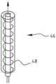
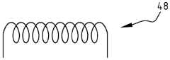
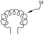
将示出根据本发明的加热器元件的几个实施方式。加热器42(图2A)包括作为导体的电阻加热材料44a和多孔陶瓷层44b。加热器46(图2B)被缠绕为螺线管48(图2C),其类似于如图1中所示的加热器28。在可选的配置中,加热器50被配置为例如环形线圈(图2D)或扁绕线圈51(图2E)或扁平螺旋线52(图2F)。Several embodiments of heater elements according to the present invention will be shown. The heater 42 (FIG. 2A) includes a
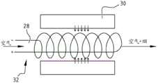
在系统2的所示实施方式中,缓冲物30被设置在空气路径28和加热器32(也见图2G)周围。在可选的实施方式中,液体储器54被设置在加热器56(图2H)的螺线管内部。In the illustrated embodiment of
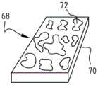
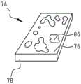
另外的可选配置包括被缠绕为环形线圈结构(其中液体穿过环形线圈结构的内部且空气流穿行在环形结构周围)的加热器58(图2I)。另一可选的配置包括被形成为扁绕线圈的加热器60(图2J)。此外,加热器62(图2K)可包括作为在覆盖的多孔陶瓷层66上的导体的电阻加热材料64的路径层,或可选地,加热器68可包括导体层70,其中,其上设置有覆盖的多孔陶瓷元件或斑72(图2L)。可选地,加热器74包括导体层76和陶瓷层78(图2M)和可选地包括额外的陶瓷斑80(图2N)。另一实施方式包括具有螺旋配置缠绕的导体84的多孔陶瓷层82(图2O)。A further optional configuration includes heater 58 (FIG. 2I) wound as a toroidal coil structure with liquid passing through the interior of the toroidal coil structure and air flow passing around the toroid structure. Another alternative configuration includes
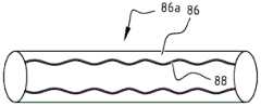
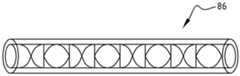
其它实施方式包括具有被覆盖有陶瓷层88的静态混合形式86a的导体管86(图2P和2Q)。作为另一可选形式,导体90是具有陶瓷层92的管(图2R)。管90a可以在内部填充有液体并且在外面具有空气流(图2S),或管90b在内部具有空气流并且在外部具有液体缓冲物(图2T)。可选地,陶瓷层设置在管90的内部和外部。此外,管90可包括具有电阻加热材料和陶瓷材料的多个较小的管或线94(图2U)。另一可选的配置(图2V)涉及覆盖有多孔陶瓷材料98的电阻加热金属泡沫或海绵96。Other embodiments include a
加热器32的所公开的实施方式提供可应用于系统2的根据发明的加热器的例子。The disclosed embodiment of
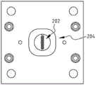
优选地使用等离子体电解氧化来制造根据本发明的加热器元件。作为例子,仅为了说明性原因,下面将公开关于根据本发明的加热器元件的一些可能的配置的一些制造方法。The heater element according to the invention is preferably manufactured using plasma electrolytic oxidation. As an example, and for illustrative reasons only, some methods of manufacture are disclosed below with respect to some possible configurations of heater elements according to the present invention.
在加热器元件的第一实施方式中,执行直接连接到阳极的钛线的等离子体电解氧化。In a first embodiment of the heater element, plasma electrolytic oxidation of the titanium wire directly connected to the anode is performed.
对于等离子体电解氧化,使用了等离子体电解室102(图3A)。工件104连接到阳极106。工件104夹/固定在两个螺钉或夹具108之间,两个螺钉或夹具108连接到电源的接地端/地线(阳极104)。在所示实施方式中,阴极110包括不锈钢蜂窝电极112,其在使用中被放置在工件104之上的近距离处。电解液114在电极112和阳极106之间流动,并连同所产生的氧气和氢气一起有效地向上流动穿过蜂窝电极112。电解液流出物116连同氢气和氧气一起然后被冷却并可选地返回到室102。在所示实施方式中,电解液114的温度从进入等离子体电解氧化室102的大约11℃增加到离开室102的25℃,并接着使用热交换器(未示出)来冷却。For plasma electrolytic oxidation, a plasma electrolysis chamber 102 (FIG. 3A) was used. The
在所示室102中,两个电源(Munk PSP系列)串联连接:一个是350伏特和40安培,而第二个是400伏特和7安培,导致750伏特和7安培的最大值,因而产生的最大功率是5.25kW。电源可直接连接到阳极106和阴极110,导致等离子体的直流(DC)操作。可选地添加的开关电路提供使用DC脉冲操作等离子体的选项。脉冲的频率可设置在DC和1kHz之间,且不同的波形(块、正弦或三角形)可被选择。优选地在脉冲电流模式中以大约1000Hz的频率(接通-关断)、优选地以设置在固定值的电流执行等离子体电解氧化,且作为多孔氧化物层的生长的结果,电压在时间上增加。在1和7安培之间的电流可用于产生陶瓷层。In the
为了产生根据本发明的加热器元件,在室102中,钛线202(图3B)被作为工件104放置在连接到不锈钢阳极的钛板204的顶部上。可选地,阳极直接连接到线202。电解液包括8g/l NaSiO3*5H2O和15g/l(NaPO3)6。使用由具有0.5mm的直径和60cm的长度的第1级钛制成的钛线。线被卷成圈并连接到阳极。高于500伏特的电势施加在阳极和阴极之间,导致在钛线的表面上的微电弧放电。在线的表面上,金属钛在添加有来自电解液的硅酸盐和磷酸盐的情况下被氧化成氧化钛。金属层转换成包含氧化钛、磷酸盐和硅酸盐的多孔陶瓷层。这导致根据本发明的加热器元件302(图5)。To create a heater element according to the present invention, in
电流增加电路402(图6A)包括电池404、变压器(trafo)406、加热器元件408和(超级)电容器410。电路402中的其它部件包括二极管412、电阻414、响应于吸气的开关416、晶体管418。将理解的是,电路402中的部件可以被用其它部件来代替和/或额外的部件可被应用。例如,可选的电路420(图6B)包括电池422、加热器元件424、电容器426、开关428、电阻器430和二极管432。The current augmentation circuit 402 ( FIG. 6A ) includes a
当开始吸气时,电容器410、426将额外的电流供应到加热器元件408、424以加速加热器元件408、424的温度增加并紧接着开始雾化和/或汽化。优选地,加热器元件由在室温下的展示相对低的电阻和在增加的温度下展示较高电阻的钛材料制成,从而实现对激活信号的快速响应时间。When inhalation begins, the
在当前优选的实施方式中,加热器元件的导体由NiCr(并且优选地由钛)制成。与NiCr相比,钛(图7)的电阻随着温度更快地增加。与定义在特定温度下的所测量的电阻的线性关系的钛的线性关系(y=0.0104x+1.5567)相比,这用NiCr的线性关系(y=0.0011x+2.164)示出。In a currently preferred embodiment, the conductors of the heater element are made of NiCr (and preferably titanium). Compared to NiCr, the resistance of titanium (Figure 7) increases more rapidly with temperature. This is shown with the linear relationship for NiCr (y=0.0011x+2.164) compared to the linear relationship for titanium (y=0.0104x+1.5567) which defines the linear relationship of the measured resistance at a specific temperature.
在电子香烟502(图8)的另一实施方式中,通过连接器504从超级电容器506对加热器32提供能量。经由外部连接器508对电容器506充电。电容器506可被(半)直接和/或间接地充电。可结合具有香烟存储隔间512和带有电池516的电池隔间514的香烟盒510来执行这样的间接充电。在充电状态中,充电连接器518接触连接器508,且超级电容器506被充电。在所示实施方式中,电池516通过连接器520是可再充电的。In another embodiment of electronic cigarette 502 ( FIG. 8 ),
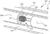
在根据本发明的前述优选实施方式中,电子香烟包括两个主要部分,第一部分具有带有空气流开关的电池和用于电子香烟的正确操作的电子控制设备,且第二部分具有能够包含电子液体的盒、加热元件和用于将电子液体运输到加热元件上的部分。盒602(图9-10)包括在所示实施方式中由不锈钢制成的金属管604,其具有位于距离管的起始A大约2.75mm处的大约0.25mm直径的八个孔606,其在使用中最接近电子香烟的接口管。在所示实施方式中,管604在长度上是大约29.1mm,其具有大约4mm的外径和大约0.3mm的壁厚。优选地由氧化锆制成的陶瓷管608在离开口大约2.5mm的位置处被设置在金属管604内部,陶瓷管608具有大约22mm的长度、大约3.4mm的外径和大约0.35mm的壁厚。In the aforementioned preferred embodiment according to the invention, the electronic cigarette comprises two main parts, the first part has the battery with the air flow switch and the electronic control device for the correct operation of the electronic cigarette, and the second part has the electronic cigarette capable of containing Cartridge for liquid, heating element and part for transporting e-liquid onto the heating element. The cassette 602 (FIGS. 9-10) includes a
陶瓷覆盖的钛加热元件610被放置在具有孔606的金属管604中。加热元件610优选地由被覆盖有陶瓷层并被缠绕为螺线管的钛线(第1级)制成。具有陶瓷层的钛线的直径是大约0.25mm,在加热元件中使用的线的总长度是大约90mm,其具有大约10个紧密间隔开的具有大约2.2mm的直径的绕组612,且加热元件610的总长度是大约1.4mm。加热元件610被放置在金属管604内部,使得第一绕组位于陶瓷管608中,防止加热元件610接触金属管604。Ceramic covered
具有孔606的金属管604在侧面A上被压成具有连接器(未示出)以及电绝缘器618的螺帽并在另一侧上被压成端帽(未示出)。金属壳体614(优选地由不锈钢制成的管)在螺帽和端帽之间延伸,其中管具有大约3.8mm的长度、大约9.2mm的直径和大约0.2mm的壁厚。在外部金属管614和具有孔606的内部金属管604之间的空间、室或隔间616可填充有电子液体。例如,电子液体包括大约60%的蔬菜甘油、大约30%的丙二醇以及大约10%含有尼古丁、调味品和水。尼古丁、调味品和水之间的比率可被调节到优选的数量。The
盒602的螺帽连接到电子香烟的电池,从而将电池的正极和负极连接到加热元件610的正和负连接器。这使电流能够穿过钛线从正极流到负极以通过焦耳加热来增加钛线的温度。电流由用户所激活的流开关控制。在使用中,空气流经具有孔606的金属管604,且电子液体被运输朝向加热元件610。通过增加加热元件610的温度,电子液体在空气流中蒸发且蒸发的电子液体被运输到用户。The screw cap of the
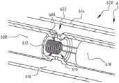
在可选的实施方式中,盒620(图10)设置有类似的部件,其中例外的是,孔606被设置在凹槽622中。In an alternative embodiment, cartridge 620 ( FIG. 10 ) is provided with similar components, with the exception that holes 606 are provided in
将理解的是,在另外的实施方式中,可组合盒602、620的部件。可在电子香烟2、502及它的其它实施方式中使用盒602、620和可选的实施方式。It will be appreciated that in further embodiments, the components of the
雾化器组件702(图11)包括壳体704。在端706处壳体704被设置有优选地被压制于壳体704中的端环(end ring)708以及密封件733。端盖710被压制于环708中。壳体704包括缓冲物或贮存器712和金属管714。流体路径716延伸通过管714。贮存器712并定位成围绕管714的外表面718。在所示的实施方式中,管714的内表面720设置有陶瓷层722。管714还包括加热器元件724。管714中的开口726实现流体从贮存器712向加热器元件724的运输。在所示出的实施方式中,管714具有直径为约0.2mm的八个开口726。要理解的是,根据本发明也可以设想其他的尺寸和形状。在端部728,壳体704被设置有连接器730。具有开口731的连接器730包括密封件732和螺纹734。连接器730的边缘或止动部736用于定位管714。此外,止动部736防止流体从贮存器712的泄露。在所示出的实施方式中,连接器730由铜材料制造成。可选地,连接器730包括具有螺纹734的(隔离)连接器部件738。组件702还包括具有开口741的环740。橡胶环742将连接器730与金属销744隔离。加热器元件724的第一支腿746连接到销744。加热器元件724的第二支腿748连接到连接器730和/或其环740。Nebulizer assembly 702 ( FIG. 11 ) includes
要理解的是,根据本发明也可以设想支腿和/或其他组件的其他配置,包括将不同的元件组合在单个部件中和/或将一个部件分离成若干子部件。It is to be understood that other configurations of legs and/or other components are also contemplated in accordance with the present invention, including combining different elements in a single component and/or separating one component into several sub-components.
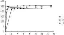
完成三个实验:1)在15分钟期间为0.5安培,2)在15分钟期间为1安培,以及3)在15分钟期间为2安培。在等离子体电解氧化之前和之后测量线的质量和直径。线被放置在水中5分钟,且质量被测量为在线上吸收的水的量的指示。可在图4中看到三个不同的电流设置的随时间的变化的电压,且在表1中呈现在氧化之前和之后的某些另外的材料信息。Three experiments were done: 1) 0.5 amps during 15 minutes, 2) 1 amp during 15 minutes, and 3) 2 amps during 15 minutes. Wire mass and diameter were measured before and after plasma electrolytic oxidation. The wire was placed in water for 5 minutes and the mass was measured as an indication of the amount of water absorbed on the wire. Voltage versus time for three different current settings can be seen in Figure 4, and some additional material information before and after oxidation is presented in Table 1.
表1:材料信息Table 1: Material Information

在不同的工艺条件(包括在一小时的处理时间期间以5安培(线1)和1安培(线2))下制造陶瓷线。结果在表2中示出。Ceramic wires were fabricated under different process conditions including 5 amps (wire 1) and 1 amp (wire 2) during a one hour processing time. The results are shown in Table 2.
表2:两个陶瓷钛线的陶瓷层的厚度、孔隙率和吸收Table 2: Thickness, porosity and absorption of ceramic layers of two ceramic titanium wires
线1:在等离子体电解氧化(PEO)之前Line 1: Before Plasma Electrolytic Oxidation (PEO)
L=0.5m、D=0.500mm、R=1.2Ω、R计算=2.44Ω/m、吸收(水)=4μlL=0.5m, D=0.500mm, R=1.2Ω, Rcalculation =2.44Ω/m, absorption (water)=4μl
线1:在PEO之后(在60分钟期间为5A)Line 1: After PEO (5A during 60 minutes)
L=0.5m、D=0.610mm、R=1.3-1.4Ω、吸收(水)=21μl、孔隙率=44%L=0.5m, D=0.610mm, R=1.3-1.4Ω, absorption (water)=21μl, porosity=44%
线2:在PEO之前:Line 2: Before PEO:
L=0.5m、D=0.500mm、V=9.8e-8m3、m=4.2992e-4kg、ρ=4379kg/m3L=0.5m, D=0.500mm, V=9.8e-8m3 , m=4.2992e-4kg, ρ=4379kg/m3
线2:在PEO之后(在60分钟期间为1A)Line 2: After PEO (1A during 60 minutes)
L=0.5m、D=0.5610mm、V=1.236e-8m3、m=4.512e-4kg、ρ=3650kg/m3、m氧化层=2.13e-5kg、V氧化层=2.56e-8m3、M没有孔隙率的估计=4.452e-5kg、孔隙率=50%,所计算的吸收=12.8μlL=0.5m, D=0.5610mm, V=1.236e-8m3 , m=4.512e-4kg, ρ=3650kg/m3 , moxide layer =2.13e-5kg, Voxide layer =2.56e-8m3 , Mestimated without porosity = 4.452e-5kg, porosity = 50%, calculated absorption = 12.8 μl
将理解的是,对于可选的线,其它条件将适用。例如,对于具有0.1mm的直径的线,R计算=61Ω/m。具有6.5cm的长度的这样的线将给出4Ω的电阻。在100μm的氧化物厚度的情况下,吸收1.3μl的量。150μm给出3.1μl以及200μm给出5.4μl。It will be understood that for optional lines, other conditions will apply. For example, for a wire with a diameter of 0.1 mm, Ris calculated = 61 Ω/m. Such a wire with a length of 6.5cm would give a resistance of 4Ω. In the case of an oxide thickness of 100 μm, an amount of 1.3 μl is absorbed. 150 μm gives 3.1 μl and 200 μm gives 5.4 μl.
实验示出根据本发明的系统的加热器元件的制造可能性。另外的实验已经被进行以产生加热器的其它配置。在一个这样的另一实验中,金属箔(优选地铝箔)优选地在早些时候描述的等离子体电解室中用作起始材料,其上提供有多孔金属(铝)氧化物层。表3示出在9分钟期间使用在5安培的恒定电流进行的等离子体电解氧化的所测量的值。13μm厚度的铝箔被氧化,其中产生13μm的氧化铝厚度,且表4示出过程的再现性。这两个表都示出对于5A的恒定电流、进入等离子体氧化室中(Tin)和从等离子体氧化室出来(Teff)的电解液的电压、电流、温度。The experiments show the manufacturing possibilities of the heater element of the system according to the invention. Additional experiments have been conducted to generate other configurations of heaters. In one such further experiment, a metal foil, preferably an aluminium foil, is preferably used as the starting material in the plasma electrolysis chamber described earlier, on which a porous metal (aluminum) oxide layer is provided. Table 3 shows the measured values for plasma electrolytic oxidation using a constant current at 5 amps during 9 minutes. A 13 μm thick aluminum foil was oxidized, which resulted in an alumina thickness of 13 μm, and Table 4 shows the reproducibility of the process. Both tables show the voltage, current, temperature of the electrolyte into the plasma oxidation chamber (Tin) and out of the plasma oxidation chamber (Teff) for a constant current of 5A.
表3table 3


表4Table 4

表5示出在2A的恒定电流下的铝箔的等离子体电解氧化的电压和电流。结果是13μm的厚氧化铝层。Table 5 shows the voltage and current for plasma electrolytic oxidation of aluminum foil at a constant current of 2A. The result is a thick aluminum oxide layer of 13 μm.
表5:使用2A的恒定电流的等离子体电解氧化的电压和电流。Table 5: Voltage and current for plasma electrolytic oxidation using a constant current of 2A.

表6示出使用5安培的1kHz的脉冲恒定电流的铝箔的等离子体电解氧化的电压和电流。Table 6 shows the voltage and current for plasma electrolytic oxidation of aluminum foil using a 5 amp pulsed constant current of 1 kHz.
表6:1kHz的脉冲恒定电流的电压和电流。Table 6: Voltage and current of pulsed constant current at 1 kHz.

在另一实验中,等离子体电解氧化用于提供在钛箔上的>70μm的多孔的、柔性的和弹性的陶瓷层。等离子体电解氧化使被已知为陶瓷(TiO2)的钛氧化物层生长。使用8g/lNa2SiO3*5H2O(五水偏硅酸钠)和15g/l(NaPO3)6(六偏磷酸钠)的电解液。电解液被泵送到反应室内以充当电解液和充当冷却剂。使用来自第2级钛的具有124μm的厚度的钛箔。在制造过程中,电压随着时间的变化而增加。这个增加表示增加的电阻,并且可以可能由氧化钛(TiOx)层的生长来解释。较厚的TiOx层充当像在金属和电解液之间的绝缘层。可在表7中看到在时间上的因而产生的电压发展。In another experiment, plasma electrolytic oxidation was used to provide >70 μm porous, flexible and elastic ceramic layers on titanium foils. Plasma electrolytic oxidation grows layers of titanium oxide known as ceramics (TiO2 ). An electrolyte of 8 g/l Na2 SiO3 * 5H2 O (sodium metasilicate pentahydrate) and 15 g/l (NaPO 3 ) 6 (sodium hexametaphosphate) was used. Electrolyte is pumped into the reaction chamber to act as electrolyte and as coolant. A titanium foil from
表7:对于使用等离子体电解氧化的在钛箔上的陶瓷层的产生的随着时间的变化的电压和电流Table 7: Voltage and current as a function of time for the generation of ceramic layers on titanium foils using plasma electrolytic oxidation

产生的箔结构可以被进一步处理(涉及电化学加工)。例如,可利用第2级钛的溶解以制成完美正方形通道。在使用电化学加工(ECM)的情况下,第2级钛以非常受控的方式局部地溶解,直到达到陶瓷层。完成的结果必须是具有正方形边缘的轮廓分明的通道且在陶瓷层的顶部上没有残渣。对具有被放置在用作阳极的钛板的顶部上的产品的反形状的阴极使用ECM过程。电势被置于阴极和阳极之间,使阳极溶解。The resulting foil structure can be further processed (involving electrochemical machining). For example, the dissolution of
电解液浓度是5M NaNO3。电流密度可以范围在20-150A/cm2。以>60A/cm2的电流密度实现最好的结果。以脉冲模式操作电流,其中电流接通和断开的时间可变化。以16-80的接通/断开比和从0.05直到10ms的脉冲接通及从1ms直到160ms的脉冲断开实现最好的结果。这个额外的处理步骤也可应用于加热器的其它配置。The electrolyte concentration was 5M NaNO3 . The current density can range from 20-150 A/cm2 . The best results were achieved with current densities >60A/cm2 . The current is operated in a pulsed mode, where the time at which the current is turned on and off can be varied. The best results were achieved with an on/off ratio of 16-80 and pulsed on from 0.05 up to 10ms and pulsed off from 1ms up to 160ms. This additional processing step can also be applied to other configurations of heaters.
在当前优选的实施方式中,加热器元件由钛线或较不优选地由NiCr线制成。图7示出对于这两种材料的与温度有关的电加热器元件的电阻。如早些时候提到的,钛的使用对加热器元件是有益的。In a presently preferred embodiment, the heater element is made of titanium wire or, less preferably, NiCr wire. Figure 7 shows the temperature-dependent electrical heater element resistance for these two materials. As mentioned earlier, the use of titanium is beneficial for heater elements.
上述实验示出制造加热器元件的不同配置并在例如电子香烟中实现这样的配置的可能性。本发明决不限于以上描述的其优选的实施方式。所寻求的权利由所附权利要求定义,在所附权利要求的范围之内,可以设想很多修改。The above experiments show the possibility of making different configurations of heater elements and implementing such configurations in e.g. electronic cigarettes. The present invention is by no means limited to its preferred embodiments described above. The rights sought are defined by the appended claims, within the scope of which many modifications are contemplated.
Claims (31)
Translated fromChineseApplications Claiming Priority (15)
| Application Number | Priority Date | Filing Date | Title |
|---|---|---|---|
| NL2014078 | 2014-12-31 | ||
| NL2014078 | 2014-12-31 | ||
| US201562102862P | 2015-01-13 | 2015-01-13 | |
| US62/102,862 | 2015-01-13 | ||
| NL2014176 | 2015-01-22 | ||
| NL2014176 | 2015-01-22 | ||
| NL2014461 | 2015-03-16 | ||
| NL2014461ANL2014461B1 (en) | 2014-12-31 | 2015-03-16 | Personal electronic delivery system and method for delivering a delivery fluid. |
| DE202015006397.7 | 2015-09-11 | ||
| DE202015006397.7UDE202015006397U1 (en) | 2014-12-31 | 2015-09-11 | Personal electronic delivery system |
| NL2015766 | 2015-11-10 | ||
| NL2015766 | 2015-11-10 | ||
| DE202015008791.4UDE202015008791U1 (en) | 2014-12-31 | 2015-12-23 | Personal electronic delivery system |
| DE202015008791.4 | 2015-12-23 | ||
| PCT/NL2015/050920WO2016108694A1 (en) | 2014-12-31 | 2015-12-30 | Personal electronic delivery system, atomizer assembly, use thereof and corresponding production method |
Publications (2)
| Publication Number | Publication Date |
|---|---|
| CN107846972A CN107846972A (en) | 2018-03-27 |
| CN107846972Btrue CN107846972B (en) | 2020-09-15 |
Family
ID=55524423
Family Applications (1)
| Application Number | Title | Priority Date | Filing Date |
|---|---|---|---|
| CN201580077238.7AActiveCN107846972B (en) | 2014-12-31 | 2015-12-30 | Personal electronic delivery system, atomizer assembly, use thereof and corresponding production method |
Country Status (4)
| Country | Link |
|---|---|
| US (1) | US10285445B2 (en) |
| EP (1) | EP3240445B1 (en) |
| CN (1) | CN107846972B (en) |
| MX (1) | MX379619B (en) |
Families Citing this family (36)
| Publication number | Priority date | Publication date | Assignee | Title |
|---|---|---|---|---|
| ES2720264T3 (en) | 2013-12-11 | 2019-07-19 | Jt Int Sa | Heating system and procedure for heating an inhaler device |
| TWI660685B (en) | 2014-05-21 | 2019-06-01 | 瑞士商菲利浦莫里斯製品股份有限公司 | Electrothermal aerosol generating system and cylinder used in the system |
| NL2014079B1 (en)* | 2014-12-31 | 2016-10-07 | Metalmembranes Com B V | Heater element, device provided therewith and method for manufacturing such element. |
| US10039324B2 (en)* | 2015-08-14 | 2018-08-07 | Tuanfang Liu | Electronic cigarette |
| NL2016546B1 (en)* | 2016-04-04 | 2017-10-10 | Sluis Cigar Machinery Bv | Electronic cigarette, and method of cleaning an electronic cigarette. |
| US10617151B2 (en)* | 2016-07-21 | 2020-04-14 | Rai Strategic Holdings, Inc. | Aerosol delivery device with a liquid transport element comprising a porous monolith and related method |
| EP3496793A1 (en)* | 2016-08-12 | 2019-06-19 | Intrepid Brands, LLC | Wickless cartomizer |
| US11903099B2 (en)* | 2016-08-12 | 2024-02-13 | Altria Client Services Llc | Vaporizer of an electronic vaping device and method of forming a vaporizer |
| US9993027B1 (en) | 2016-12-06 | 2018-06-12 | Funai Electric Co., Ltd. | Heater element for a vaporization device |
| US10834967B2 (en)* | 2016-12-27 | 2020-11-17 | Gofire, Inc. | System and method for managing concentrate usage of a user |
| EP3494811B1 (en)* | 2017-12-07 | 2021-03-17 | Fontem Holdings 1 B.V. | Electronic smoking device with a heating element having a modified surface |
| GB201802590D0 (en) | 2018-02-16 | 2018-04-04 | Nicoventures Trading Ltd | Aerosol provision article |
| GB201802591D0 (en) | 2018-02-16 | 2018-04-04 | Nicoventures Trading Ltd | Aerosol provision article |
| GB201805510D0 (en)* | 2018-04-04 | 2018-05-16 | Nicoventures Trading Ltd | Vapour provision systems |
| KR102274250B1 (en)* | 2018-04-09 | 2021-07-07 | 주식회사 아모센스 | heater for electronic cigarette device |
| JP7544603B2 (en)* | 2018-06-28 | 2024-09-03 | フィリップ・モーリス・プロダクツ・ソシエテ・アノニム | Cartridge for an aerosol generating system containing a nicotine source including a liquid nicotine formulation |
| EP3838034B1 (en)* | 2018-08-13 | 2023-08-09 | Japan Tobacco Inc. | Flavor generation system, method, and program |
| US20200323269A1 (en)* | 2018-08-17 | 2020-10-15 | Shenzhen Relx Technology Co., Ltd. | Vaporization device and method thereof |
| US11265974B2 (en)* | 2018-08-27 | 2022-03-01 | Rai Strategic Holdings, Inc. | Aerosol delivery device with integrated thermal conductor |
| CN209284320U (en)* | 2018-10-08 | 2019-08-23 | 深圳麦克韦尔股份有限公司 | Electronic cigarette and its atomizer and heat generating component |
| CN109674092A (en)* | 2019-01-23 | 2019-04-26 | 深圳麦克韦尔股份有限公司 | Heating wire and electronic atomization device |
| WO2020200773A1 (en)* | 2019-04-04 | 2020-10-08 | Ventus Medical Limited | A heater assembly |
| CN110292212B (en)* | 2019-07-08 | 2024-03-29 | 广东金莱特智能科技有限公司 | Electronic cigarette, air flow switch support thereof, air flow switch assembly and power supply device |
| EP4025087A4 (en)* | 2019-09-05 | 2023-10-11 | Hexo Operations Inc. | Vaporization device with liquid management |
| WO2021122801A1 (en)* | 2019-12-18 | 2021-06-24 | Jt International Sa | Aerosol generation device power system |
| CA3162544A1 (en) | 2019-12-23 | 2021-07-01 | Pax Labs, Inc. | Vaporizer cartridge |
| US20210401052A1 (en)* | 2020-06-24 | 2021-12-30 | Vuber Technologies, Llc | Vaporization device using frustal porous vaporization media |
| US11839239B2 (en) | 2020-08-12 | 2023-12-12 | DES Products Ltd. | Adjustable airflow cartridge for electronic vaporizer |
| WO2022037290A1 (en)* | 2020-08-19 | 2022-02-24 | Shenzhen Innokin Technology Co., Ltd | Heating apparatus, non-combusted heating device, and method for manufacturing the same |
| EP4233150B1 (en)* | 2020-10-26 | 2024-12-04 | JT International SA | Aerosol generation device power system |
| CN115428987A (en)* | 2021-06-04 | 2022-12-06 | 深圳市合元科技有限公司 | Aerosol generating device, heater for aerosol generating device and manufacturing method |
| USD1028336S1 (en) | 2021-06-22 | 2024-05-21 | Pax Labs, Inc. | Vaporizer cartridge |
| CN116268599A (en)* | 2021-12-20 | 2023-06-23 | 深圳麦克韦尔科技有限公司 | Atomizers and Atomizers |
| CN218008193U (en)* | 2021-12-31 | 2022-12-13 | 江门摩尔科技有限公司 | Electronic atomization device |
| EP4234126A1 (en)* | 2022-02-23 | 2023-08-30 | ETH Zurich | Metallic foams and methods for producing them |
| EP4360481A1 (en)* | 2022-10-25 | 2024-05-01 | EQOY International Group AG | A handheld device for vaporizing liquid to be inhaled by a user |
Citations (6)
| Publication number | Priority date | Publication date | Assignee | Title |
|---|---|---|---|---|
| CN1196660A (en)* | 1996-06-17 | 1998-10-21 | 日本烟业产业株式会社 | Flavor producing article |
| CN201238609Y (en)* | 2008-07-21 | 2009-05-20 | 北京格林世界科技发展有限公司 | Electronic atomizer for electronic cigarette |
| EP2404515A1 (en)* | 2009-02-11 | 2012-01-11 | Lik Hon | Improved atomizing electronic cigarette |
| CN103720047A (en)* | 2013-12-13 | 2014-04-16 | 浙江中烟工业有限责任公司 | Non-combustion smoking device on basis of graphite heating |
| CN103859604A (en)* | 2014-01-23 | 2014-06-18 | 深圳市康尔科技有限公司 | Heating component and atomizing structure of electronic cigarette |
| EP2807935A1 (en)* | 2012-01-25 | 2014-12-03 | Maas, Bernard Karel | Electronic simulation cigarette and atomizer thereof |
Family Cites Families (7)
| Publication number | Priority date | Publication date | Assignee | Title |
|---|---|---|---|---|
| US5530225A (en) | 1991-03-11 | 1996-06-25 | Philip Morris Incorporated | Interdigitated cylindrical heater for use in an electrical smoking article |
| US5498855A (en) | 1992-09-11 | 1996-03-12 | Philip Morris Incorporated | Electrically powered ceramic composite heater |
| UA112883C2 (en) | 2011-12-08 | 2016-11-10 | Філіп Морріс Продактс С.А. | DEVICE FOR THE FORMATION OF AEROSOL WITH A CAPILLARY BORDER LAYER |
| US8881737B2 (en)* | 2012-09-04 | 2014-11-11 | R.J. Reynolds Tobacco Company | Electronic smoking article comprising one or more microheaters |
| GB2515992A (en) | 2013-03-22 | 2015-01-14 | British American Tobacco Co | Heating smokeable material |
| CN103960782B (en)* | 2013-09-29 | 2016-09-21 | 深圳麦克韦尔股份有限公司 | Electronic cigarette |
| WO2016108694A1 (en) | 2014-12-31 | 2016-07-07 | UTVG Global IP B.V. | Personal electronic delivery system, atomizer assembly, use thereof and corresponding production method |
- 2015
- 2015-12-30CNCN201580077238.7Apatent/CN107846972B/enactiveActive
- 2015-12-30MXMX2017008761Apatent/MX379619B/enunknown
- 2015-12-30USUS15/541,321patent/US10285445B2/ennot_activeExpired - Fee Related
- 2015-12-30EPEP15841120.7Apatent/EP3240445B1/enactiveActive
Patent Citations (6)
| Publication number | Priority date | Publication date | Assignee | Title |
|---|---|---|---|---|
| CN1196660A (en)* | 1996-06-17 | 1998-10-21 | 日本烟业产业株式会社 | Flavor producing article |
| CN201238609Y (en)* | 2008-07-21 | 2009-05-20 | 北京格林世界科技发展有限公司 | Electronic atomizer for electronic cigarette |
| EP2404515A1 (en)* | 2009-02-11 | 2012-01-11 | Lik Hon | Improved atomizing electronic cigarette |
| EP2807935A1 (en)* | 2012-01-25 | 2014-12-03 | Maas, Bernard Karel | Electronic simulation cigarette and atomizer thereof |
| CN103720047A (en)* | 2013-12-13 | 2014-04-16 | 浙江中烟工业有限责任公司 | Non-combustion smoking device on basis of graphite heating |
| CN103859604A (en)* | 2014-01-23 | 2014-06-18 | 深圳市康尔科技有限公司 | Heating component and atomizing structure of electronic cigarette |
Non-Patent Citations (1)
| Title |
|---|
| 多孔陶瓷膜制备技术研究进展;范益群 等;《化工学报》;20130131;第64卷(第1期);全文* |
Also Published As
| Publication number | Publication date |
|---|---|
| EP3240445B1 (en) | 2019-07-03 |
| MX379619B (en) | 2025-03-11 |
| US10285445B2 (en) | 2019-05-14 |
| US20170347714A1 (en) | 2017-12-07 |
| EP3240445A1 (en) | 2017-11-08 |
| CN107846972A (en) | 2018-03-27 |
| MX2017008761A (en) | 2018-03-23 |
Similar Documents
| Publication | Publication Date | Title |
|---|---|---|
| CN107846972B (en) | Personal electronic delivery system, atomizer assembly, use thereof and corresponding production method | |
| WO2016108694A1 (en) | Personal electronic delivery system, atomizer assembly, use thereof and corresponding production method | |
| CN205492620U (en) | A individual electron conveying system for being directed at conveyance fluid is carried | |
| WO2016118005A1 (en) | Electronic delivery unit and cartridge, an e-cigarette comprising the unit and cartridge, and method for delivering a delivery fluid | |
| WO2017082728A1 (en) | Cartridge for a personal electronic delivery system, such system, use and method there for | |
| US20180007741A1 (en) | Heater element, device provided therewith and method for manufacturing such element | |
| JP7323132B2 (en) | Electronic aerosol delivery system and vaporizer for electronic aerosol delivery system | |
| CN107801375B (en) | Heater assembly for aerosol-generating system | |
| CN102883766B (en) | Planar evaporator | |
| CN107708452B (en) | Electronic aerosol supply system | |
| JP7470260B2 (en) | Atomizer core and manufacturing method thereof | |
| CN113891659B (en) | Aerosol generating device and system with conductivity sensor | |
| CN119837310A (en) | Cartridge for an aerosol-generating system | |
| CN114451586A (en) | Atomizer core with nano metal coating layer | |
| CN112423611A (en) | Improved aerosol-generating system comprising individually activatable heating elements | |
| JP2022544744A (en) | Aerosol generator and method of generating mixed aerosol | |
| EP3247234B1 (en) | Electronic delivery unit and cartridge, an e-cigarette comprising the unit and cartridge, and method for delivering a delivery fluid | |
| CN114190608A (en) | Resistance heater for aerosol-generating device and aerosol-generating device | |
| NL2014461B1 (en) | Personal electronic delivery system and method for delivering a delivery fluid. | |
| NL2014460B1 (en) | Personal electronic delivery unit and cartridge, an e-cigarette comprising the unit and cartridge, and method for delivering a delivery fluid. | |
| CN217089633U (en) | Atomizing core and electronic atomization device | |
| EP4444120A1 (en) | Hybrid aerosol-generating system with modular consumable | |
| EP4266922B1 (en) | Cartridge for use in an aerosol-generating system | |
| CN117120388A (en) | Conductive coated porous sintered body with uniform layer thickness |
Legal Events
| Date | Code | Title | Description |
|---|---|---|---|
| PB01 | Publication | ||
| PB01 | Publication | ||
| SE01 | Entry into force of request for substantive examination | ||
| SE01 | Entry into force of request for substantive examination | ||
| GR01 | Patent grant | ||
| GR01 | Patent grant |