CN107810404B - Methods, carrier assemblies and systems for imaging samples for biological or chemical analysis - Google Patents
Methods, carrier assemblies and systems for imaging samples for biological or chemical analysisDownload PDFInfo
- Publication number
- CN107810404B CN107810404BCN201680024922.3ACN201680024922ACN107810404BCN 107810404 BCN107810404 BCN 107810404BCN 201680024922 ACN201680024922 ACN 201680024922ACN 107810404 BCN107810404 BCN 107810404B
- Authority
- CN
- China
- Prior art keywords
- substrate
- carrier assembly
- imaging
- sample
- optical
- Prior art date
- Legal status (The legal status is an assumption and is not a legal conclusion. Google has not performed a legal analysis and makes no representation as to the accuracy of the status listed.)
- Active
Links
Images


Classifications
- B—PERFORMING OPERATIONS; TRANSPORTING
- B01—PHYSICAL OR CHEMICAL PROCESSES OR APPARATUS IN GENERAL
- B01L—CHEMICAL OR PHYSICAL LABORATORY APPARATUS FOR GENERAL USE
- B01L9/00—Supporting devices; Holding devices
- B01L9/52—Supports specially adapted for flat sample carriers, e.g. for plates, slides, chips
- B01L9/527—Supports specially adapted for flat sample carriers, e.g. for plates, slides, chips for microfluidic devices, e.g. used for lab-on-a-chip
- B—PERFORMING OPERATIONS; TRANSPORTING
- B01—PHYSICAL OR CHEMICAL PROCESSES OR APPARATUS IN GENERAL
- B01L—CHEMICAL OR PHYSICAL LABORATORY APPARATUS FOR GENERAL USE
- B01L3/00—Containers or dishes for laboratory use, e.g. laboratory glassware; Droppers
- B01L3/50—Containers for the purpose of retaining a material to be analysed, e.g. test tubes
- B01L3/502—Containers for the purpose of retaining a material to be analysed, e.g. test tubes with fluid transport, e.g. in multi-compartment structures
- B01L3/5027—Containers for the purpose of retaining a material to be analysed, e.g. test tubes with fluid transport, e.g. in multi-compartment structures by integrated microfluidic structures, i.e. dimensions of channels and chambers are such that surface tension forces are important, e.g. lab-on-a-chip
- B—PERFORMING OPERATIONS; TRANSPORTING
- B01—PHYSICAL OR CHEMICAL PROCESSES OR APPARATUS IN GENERAL
- B01L—CHEMICAL OR PHYSICAL LABORATORY APPARATUS FOR GENERAL USE
- B01L7/00—Heating or cooling apparatus; Heat insulating devices
- B01L7/52—Heating or cooling apparatus; Heat insulating devices with provision for submitting samples to a predetermined sequence of different temperatures, e.g. for treating nucleic acid samples
- B—PERFORMING OPERATIONS; TRANSPORTING
- B01—PHYSICAL OR CHEMICAL PROCESSES OR APPARATUS IN GENERAL
- B01L—CHEMICAL OR PHYSICAL LABORATORY APPARATUS FOR GENERAL USE
- B01L9/00—Supporting devices; Holding devices
- B01L9/52—Supports specially adapted for flat sample carriers, e.g. for plates, slides, chips
- C—CHEMISTRY; METALLURGY
- C12—BIOCHEMISTRY; BEER; SPIRITS; WINE; VINEGAR; MICROBIOLOGY; ENZYMOLOGY; MUTATION OR GENETIC ENGINEERING
- C12Q—MEASURING OR TESTING PROCESSES INVOLVING ENZYMES, NUCLEIC ACIDS OR MICROORGANISMS; COMPOSITIONS OR TEST PAPERS THEREFOR; PROCESSES OF PREPARING SUCH COMPOSITIONS; CONDITION-RESPONSIVE CONTROL IN MICROBIOLOGICAL OR ENZYMOLOGICAL PROCESSES
- C12Q1/00—Measuring or testing processes involving enzymes, nucleic acids or microorganisms; Compositions therefor; Processes of preparing such compositions
- C12Q1/68—Measuring or testing processes involving enzymes, nucleic acids or microorganisms; Compositions therefor; Processes of preparing such compositions involving nucleic acids
- C12Q1/6813—Hybridisation assays
- C12Q1/6834—Enzymatic or biochemical coupling of nucleic acids to a solid phase
- C12Q1/6837—Enzymatic or biochemical coupling of nucleic acids to a solid phase using probe arrays or probe chips
- C—CHEMISTRY; METALLURGY
- C12—BIOCHEMISTRY; BEER; SPIRITS; WINE; VINEGAR; MICROBIOLOGY; ENZYMOLOGY; MUTATION OR GENETIC ENGINEERING
- C12Q—MEASURING OR TESTING PROCESSES INVOLVING ENZYMES, NUCLEIC ACIDS OR MICROORGANISMS; COMPOSITIONS OR TEST PAPERS THEREFOR; PROCESSES OF PREPARING SUCH COMPOSITIONS; CONDITION-RESPONSIVE CONTROL IN MICROBIOLOGICAL OR ENZYMOLOGICAL PROCESSES
- C12Q1/00—Measuring or testing processes involving enzymes, nucleic acids or microorganisms; Compositions therefor; Processes of preparing such compositions
- C12Q1/68—Measuring or testing processes involving enzymes, nucleic acids or microorganisms; Compositions therefor; Processes of preparing such compositions involving nucleic acids
- C12Q1/6869—Methods for sequencing
- G—PHYSICS
- G01—MEASURING; TESTING
- G01N—INVESTIGATING OR ANALYSING MATERIALS BY DETERMINING THEIR CHEMICAL OR PHYSICAL PROPERTIES
- G01N21/00—Investigating or analysing materials by the use of optical means, i.e. using sub-millimetre waves, infrared, visible or ultraviolet light
- G01N21/01—Arrangements or apparatus for facilitating the optical investigation
- G01N21/13—Moving of cuvettes or solid samples to or from the investigating station
- G—PHYSICS
- G01—MEASURING; TESTING
- G01N—INVESTIGATING OR ANALYSING MATERIALS BY DETERMINING THEIR CHEMICAL OR PHYSICAL PROPERTIES
- G01N21/00—Investigating or analysing materials by the use of optical means, i.e. using sub-millimetre waves, infrared, visible or ultraviolet light
- G01N21/17—Systems in which incident light is modified in accordance with the properties of the material investigated
- G01N21/25—Colour; Spectral properties, i.e. comparison of effect of material on the light at two or more different wavelengths or wavelength bands
- G01N21/251—Colorimeters; Construction thereof
- G01N21/253—Colorimeters; Construction thereof for batch operation, i.e. multisample apparatus
- G—PHYSICS
- G01—MEASURING; TESTING
- G01N—INVESTIGATING OR ANALYSING MATERIALS BY DETERMINING THEIR CHEMICAL OR PHYSICAL PROPERTIES
- G01N21/00—Investigating or analysing materials by the use of optical means, i.e. using sub-millimetre waves, infrared, visible or ultraviolet light
- G01N21/62—Systems in which the material investigated is excited whereby it emits light or causes a change in wavelength of the incident light
- G01N21/63—Systems in which the material investigated is excited whereby it emits light or causes a change in wavelength of the incident light optically excited
- G01N21/64—Fluorescence; Phosphorescence
- G01N21/645—Specially adapted constructive features of fluorimeters
- G01N21/6452—Individual samples arranged in a regular 2D-array, e.g. multiwell plates
- G—PHYSICS
- G01—MEASURING; TESTING
- G01N—INVESTIGATING OR ANALYSING MATERIALS BY DETERMINING THEIR CHEMICAL OR PHYSICAL PROPERTIES
- G01N35/00—Automatic analysis not limited to methods or materials provided for in any single one of groups G01N1/00 - G01N33/00; Handling materials therefor
- G01N35/02—Automatic analysis not limited to methods or materials provided for in any single one of groups G01N1/00 - G01N33/00; Handling materials therefor using a plurality of sample containers moved by a conveyor system past one or more treatment or analysis stations
- G01N35/04—Details of the conveyor system
- G—PHYSICS
- G01—MEASURING; TESTING
- G01N—INVESTIGATING OR ANALYSING MATERIALS BY DETERMINING THEIR CHEMICAL OR PHYSICAL PROPERTIES
- G01N35/00—Automatic analysis not limited to methods or materials provided for in any single one of groups G01N1/00 - G01N33/00; Handling materials therefor
- G01N35/10—Devices for transferring samples or any liquids to, in, or from, the analysis apparatus, e.g. suction devices, injection devices
- G01N35/1095—Devices for transferring samples or any liquids to, in, or from, the analysis apparatus, e.g. suction devices, injection devices for supplying the samples to flow-through analysers
- G—PHYSICS
- G02—OPTICS
- G02B—OPTICAL ELEMENTS, SYSTEMS OR APPARATUS
- G02B21/00—Microscopes
- G02B21/34—Microscope slides, e.g. mounting specimens on microscope slides
- B—PERFORMING OPERATIONS; TRANSPORTING
- B01—PHYSICAL OR CHEMICAL PROCESSES OR APPARATUS IN GENERAL
- B01L—CHEMICAL OR PHYSICAL LABORATORY APPARATUS FOR GENERAL USE
- B01L2300/00—Additional constructional details
- B01L2300/06—Auxiliary integrated devices, integrated components
- B01L2300/0627—Sensor or part of a sensor is integrated
- B01L2300/0654—Lenses; Optical fibres
- B—PERFORMING OPERATIONS; TRANSPORTING
- B01—PHYSICAL OR CHEMICAL PROCESSES OR APPARATUS IN GENERAL
- B01L—CHEMICAL OR PHYSICAL LABORATORY APPARATUS FOR GENERAL USE
- B01L2300/00—Additional constructional details
- B01L2300/08—Geometry, shape and general structure
- B01L2300/0809—Geometry, shape and general structure rectangular shaped
- B01L2300/0816—Cards, e.g. flat sample carriers usually with flow in two horizontal directions
- B—PERFORMING OPERATIONS; TRANSPORTING
- B01—PHYSICAL OR CHEMICAL PROCESSES OR APPARATUS IN GENERAL
- B01L—CHEMICAL OR PHYSICAL LABORATORY APPARATUS FOR GENERAL USE
- B01L2300/00—Additional constructional details
- B01L2300/08—Geometry, shape and general structure
- B01L2300/0809—Geometry, shape and general structure rectangular shaped
- B01L2300/0822—Slides
- B—PERFORMING OPERATIONS; TRANSPORTING
- B01—PHYSICAL OR CHEMICAL PROCESSES OR APPARATUS IN GENERAL
- B01L—CHEMICAL OR PHYSICAL LABORATORY APPARATUS FOR GENERAL USE
- B01L2300/00—Additional constructional details
- B01L2300/08—Geometry, shape and general structure
- B01L2300/0861—Configuration of multiple channels and/or chambers in a single devices
- B01L2300/0877—Flow chambers
- G—PHYSICS
- G01—MEASURING; TESTING
- G01N—INVESTIGATING OR ANALYSING MATERIALS BY DETERMINING THEIR CHEMICAL OR PHYSICAL PROPERTIES
- G01N35/00—Automatic analysis not limited to methods or materials provided for in any single one of groups G01N1/00 - G01N33/00; Handling materials therefor
- G01N2035/00346—Heating or cooling arrangements
- G01N2035/00356—Holding samples at elevated temperature (incubation)
- G—PHYSICS
- G01—MEASURING; TESTING
- G01N—INVESTIGATING OR ANALYSING MATERIALS BY DETERMINING THEIR CHEMICAL OR PHYSICAL PROPERTIES
- G01N35/00—Automatic analysis not limited to methods or materials provided for in any single one of groups G01N1/00 - G01N33/00; Handling materials therefor
- G01N35/00584—Control arrangements for automatic analysers
- G01N35/00722—Communications; Identification
- G01N35/00732—Identification of carriers, materials or components in automatic analysers
- G01N2035/00742—Type of codes
- G01N2035/00752—Type of codes bar codes
- G—PHYSICS
- G01—MEASURING; TESTING
- G01N—INVESTIGATING OR ANALYSING MATERIALS BY DETERMINING THEIR CHEMICAL OR PHYSICAL PROPERTIES
- G01N35/00—Automatic analysis not limited to methods or materials provided for in any single one of groups G01N1/00 - G01N33/00; Handling materials therefor
- G01N35/00584—Control arrangements for automatic analysers
- G01N35/00722—Communications; Identification
- G01N2035/00891—Displaying information to the operator
- G01N2035/0091—GUI [graphical user interfaces]
- G—PHYSICS
- G01—MEASURING; TESTING
- G01N—INVESTIGATING OR ANALYSING MATERIALS BY DETERMINING THEIR CHEMICAL OR PHYSICAL PROPERTIES
- G01N2201/00—Features of devices classified in G01N21/00
- G01N2201/02—Mechanical
- G01N2201/025—Mechanical control of operations
Landscapes
- Chemical & Material Sciences (AREA)
- Health & Medical Sciences (AREA)
- Life Sciences & Earth Sciences (AREA)
- Physics & Mathematics (AREA)
- Analytical Chemistry (AREA)
- General Health & Medical Sciences (AREA)
- Biochemistry (AREA)
- Immunology (AREA)
- General Physics & Mathematics (AREA)
- Pathology (AREA)
- Organic Chemistry (AREA)
- Proteomics, Peptides & Aminoacids (AREA)
- Zoology (AREA)
- Engineering & Computer Science (AREA)
- Wood Science & Technology (AREA)
- Clinical Laboratory Science (AREA)
- Chemical Kinetics & Catalysis (AREA)
- Molecular Biology (AREA)
- Microbiology (AREA)
- Biotechnology (AREA)
- Biophysics (AREA)
- Bioinformatics & Cheminformatics (AREA)
- General Engineering & Computer Science (AREA)
- Genetics & Genomics (AREA)
- Dispersion Chemistry (AREA)
- Optics & Photonics (AREA)
- Spectroscopy & Molecular Physics (AREA)
- Nuclear Medicine, Radiotherapy & Molecular Imaging (AREA)
- Hematology (AREA)
- Investigating, Analyzing Materials By Fluorescence Or Luminescence (AREA)
- Apparatus Associated With Microorganisms And Enzymes (AREA)
- Automatic Analysis And Handling Materials Therefor (AREA)
- Optical Measuring Cells (AREA)
- Measuring Or Testing Involving Enzymes Or Micro-Organisms (AREA)
Abstract
Translated fromChineseDescription
Translated fromChinese相关申请的交叉引用CROSS-REFERENCE TO RELATED APPLICATIONS
本申请要求于2015年3月24日提交的美国临时专利申请第62/137,600号的利益,其通过引用以其整体并入本文。This application claims the benefit of US Provisional Patent Application No. 62/137,600, filed March 24, 2015, which is incorporated herein by reference in its entirety.
发明背景Background of the Invention
本发明的实施方式大体上涉及生物或化学分析,且更特别地涉及用于检测来自样品的光信号以用于生物或化学分析的方法、载体组件和系统。Embodiments of the present invention relate generally to biological or chemical analysis, and more particularly to methods, carrier assemblies and systems for detecting optical signals from a sample for biological or chemical analysis.
用于生物或化学研究的各种测定方案涉及进行大量受控反应。在一些情况下,受控反应在支撑表面上进行。然后可以观察和分析指定的反应,以帮助识别指定反应中所涉及的化学物质的性质或特性。例如,在一些方案中,包括可识别标记(例如荧光标记)的化学组成部分可以在受控条件下选择性地结合到另一化学组成部分。可以通过用辐射激发标记并检测来自标记的光发射来观察这些化学反应。Various assay protocols for biological or chemical research involve performing a large number of controlled reactions. In some cases, the controlled reaction takes place on the support surface. The specified reaction can then be observed and analyzed to help identify the properties or properties of the chemicals involved in the specified reaction. For example, in some schemes, a chemical moiety that includes an identifiable label (eg, a fluorescent label) can selectively bind to another chemical moiety under controlled conditions. These chemical reactions can be observed by exciting the label with radiation and detecting the light emission from the label.
这些方案的示例包括DNA测序和基于多重阵列的测定。在一个边合成边测序(SBS)方案中,克隆扩增子的簇通过桥式PCR在流动池的通道的表面上形成。在生成克隆扩增子的簇之后,扩增子可以被“线性化”以制造单链DNA(sstDNA)。试剂的预定序列可以流入流动池内以完成测序周期。每个测序周期将sstDNA延长具有独特荧光标记的单个核苷酸(例如A、T、G、C)。每个核苷酸都具有允许在一个周期中仅出现单碱基掺入的可逆终止子。在将核苷酸添加到sstDNA簇后,获取在四个通道中的图像(即,针对每个荧光标记有一个通道)。在成像后,荧光标记和终止子从sstDNA化学地分开,且生长的DNA链为另一周期作准备。可以重复试剂输送和光学检测的几个周期以确定克隆扩增子的核酸的序列。Examples of these protocols include DNA sequencing and multiplex array-based assays. In a sequencing-by-synthesis (SBS) protocol, clusters of cloned amplicons are formed by bridge PCR on the surface of a channel of a flow cell. After generating clusters of cloned amplicons, the amplicons can be "linearized" to make single-stranded DNA (sstDNA). A predetermined sequence of reagents can flow into the flow cell to complete the sequencing cycle. Each sequencing cycle extends sstDNA by a single nucleotide with a unique fluorescent label (eg, A, T, G, C). Each nucleotide has a reversible terminator that allows only single base incorporation in a cycle. After adding nucleotides to the sstDNA clusters, images were acquired in four channels (ie, one channel for each fluorescent label). After imaging, the fluorescent label and terminator are chemically separated from the sstDNA, and the growing DNA strand is ready for another cycle. Several cycles of reagent delivery and optical detection can be repeated to determine the sequence of the nucleic acid of the cloned amplicon.
在一些基于多重阵列的测定方案中,将不同探针分子的群体固定到基底表面。可以基于每个探针在基底表面上的地址来区分探针。例如,探针分子的每个群体可以具有在基底表面上的已知位置(例如,网格上的坐标)。探针分子在受控条件下暴露于目标分析物,使得由于在目标分析物和探针之间的特定相互作用,可检测的变化在一个或更多个地址处出现。例如,可以基于荧光标记到探针的地址的聚集来识别与特定探针结合的荧光标记的目标分析物。阵列上的地址可以由测定系统确定,以识别哪些群体与分析物反应。通过知道与分析物反应的探针分子的化学结构,可以确定分析物的性质。在其他多重测定中,指定的反应在可以被扫描和分析的单独可识别的微粒的表面上进行。In some multiplex array-based assay protocols, populations of different probe molecules are immobilized to the substrate surface. The probes can be distinguished based on the address of each probe on the substrate surface. For example, each population of probe molecules can have a known location on the substrate surface (eg, coordinates on a grid). The probe molecule is exposed to the target analyte under controlled conditions such that a detectable change occurs at one or more addresses due to specific interactions between the target analyte and the probe. For example, fluorescently labeled target analytes bound to specific probes can be identified based on the aggregation of fluorescent labels to the addresses of the probes. The addresses on the array can be determined by the assay system to identify which populations react with the analyte. By knowing the chemical structure of the probe molecule that reacts with the analyte, the properties of the analyte can be determined. In other multiplex assays, specified reactions are performed on the surface of individually identifiable particles that can be scanned and analyzed.
不同的测定方案(诸如上面描述的那些)可以包括特定特征或涉及特定步骤,其在其他测定方案中不发生。例如,不同的测定方案可以使用不同类型的试剂或具有独特修饰性试剂、具有不同发射光谱的标记、用于支持样品的不同类型的光学基底(例如,流动池、开放面基底、微阵列、井(well)、微粒)、具有不同激发光谱的不同光源、不同的光学部件(例如物镜)、热条件和软件。此外,由于检测发生在几微米或更小的分辨率下,因此设备通常在高精度水平下操作。作为结果,现今存在的平台通常涉及执行仅仅一种类型的测定方案。Different assay protocols, such as those described above, may include specific features or involve specific steps that do not occur in other assay protocols. For example, different assay protocols may use different types of reagents or reagents with unique modifications, labels with different emission spectra, different types of optical substrates (eg, flow cells, open surface substrates, microarrays, wells) to support the sample (well), microparticles), different light sources with different excitation spectra, different optics (eg objective), thermal conditions and software. Furthermore, since detection occurs at a resolution of a few microns or less, devices typically operate at a high level of precision. As a result, the platforms that exist today typically involve performing only one type of assay protocol.
因此,存在对于能够进行多于一种类型的测定方案的测定系统和相应的部件的需要。Accordingly, there is a need for an assay system and corresponding components capable of performing more than one type of assay protocol.
发明简述Brief description of the invention
在实施方式中,提供了一种方法,其包括将第一载体组件定位在系统台上。第一载体组件包括支撑框架,其具有限定支撑框架的窗口的内框架边缘。第一载体组件包括位于窗口内并被内框架边缘包围的可移除的第一基底。第一基底在其上具有位于光学系统的成像区内的样品。该方法还包括根据第一成像方案使用光学系统检测来自第一基底的样品的光信号。该方法还包括在系统台上用第二载体组件代替第一载体组件。第二载体组件具有可移除的第二基底。第二基底在其上具有位于光学系统的成像区内的样品,其中第一和第二基底是不同类型的基底。该方法还包括根据与第一成像方案不同的第二成像方案使用光学系统检测来自第二基底的样品的光信号。可选地,第一成像方案和/或第二成像方案是自动化的。In an embodiment, a method is provided that includes positioning a first carrier assembly on a system stage. The first carrier assembly includes a support frame having an inner frame edge that defines a window of the support frame. The first carrier assembly includes a removable first substrate located within the window and surrounded by an edge of the inner frame. The first substrate has thereon the sample within the imaging region of the optical system. The method also includes detecting an optical signal from the sample of the first substrate using the optical system according to the first imaging scheme. The method also includes replacing the first carrier assembly with a second carrier assembly on the system stage. The second carrier assembly has a removable second base. The second substrate has thereon the sample within the imaging region of the optical system, wherein the first and second substrates are different types of substrates. The method also includes detecting, using an optical system, an optical signal from the sample of the second substrate according to a second imaging scheme different from the first imaging scheme. Optionally, the first imaging protocol and/or the second imaging protocol is automated.
根据实施方式,提供了一种方法,其包括将第一载体组件定位在系统台上。载体组件包括支撑框架,其具有限定支撑框架的窗口的内框架边缘。第一载体组件包括位于窗口内并被内框架边缘包围的第一基底。第一基底在其上具有位于光学系统的成像区内的样品。该方法包括使用光学系统检测来自第一基底的样品的光信号。该方法还包括用系统台上的第二载体组件代替系统台上的第一载体组件。第二载体组件包括支撑框架和由支撑框架保持的接装板。第二载体组件具有由接装板保持的第二基底,第二基底在其上具有样品。第二基底的样品位于光学系统的成像区内。该方法还包括使用光学系统检测来自第二基底的样品的光信号。According to an embodiment, a method is provided that includes positioning a first carrier assembly on a system table. The carrier assembly includes a support frame having an inner frame edge that defines a window of the support frame. The first carrier assembly includes a first substrate positioned within the window and surrounded by an edge of the inner frame. The first substrate has thereon the sample within the imaging region of the optical system. The method includes detecting an optical signal from a sample of the first substrate using an optical system. The method also includes replacing the first carrier assembly on the system table with the second carrier assembly on the system table. The second carrier assembly includes a support frame and an adapter plate held by the support frame. The second carrier assembly has a second substrate held by a tipping plate, the second substrate having the sample thereon. The sample of the second substrate is located within the imaging region of the optical system. The method also includes detecting an optical signal from the sample of the second substrate using the optical system.
根据实施方式,提供了一种载体组件,其包括具有限定支撑框架的窗口的内框架边缘的支撑框架和耦合到支撑框架并且位于窗口内的接装板。接装板包括板主体,该板主体具有内板边缘,其限定用于接纳尺寸小于窗口的基底的接收部(pocket)。内板边缘还限定向接收部敞开的保持凹部。载体组件还包括位于保持凹部内的可移动基准块。基准块在缩回位置和接合位置之间可移动。基准块被配置为当基准块在接合位置上时接合基底,并且将基底压靠在接装板的相对表面上以将基底保持在接收部内。According to an embodiment, a carrier assembly is provided that includes a support frame having an inner frame edge defining a window of the support frame and an adapter plate coupled to the support frame and positioned within the window. The adapter plate includes a plate body having an inner plate edge that defines a pocket for receiving a substrate having dimensions smaller than the window. The inner panel edge also defines a retaining recess that is open to the receiving portion. The carrier assembly also includes a movable fiducial block located within the retaining recess. The datum block is movable between a retracted position and an engaged position. The datum block is configured to engage the substrate when the datum block is in the engaged position, and to press the substrate against opposing surfaces of the adapter plate to retain the substrate within the receptacle.
根据实施方式,提供了一种载体组件,其包括支撑框架,其具有限定支撑框架的窗口的内框架边缘。载体组件还包括耦合到支撑框架并且位于窗口内的接装板。内框架边缘限定位于接装板上方的基底接纳凹部。基底接纳凹部被配置成接纳第一平面基底。接装板包括具有内板边缘的板主体,该内板边缘限定用于接纳尺寸比第一平面基底小的第二平面基底的接收部。接收部至少部分地存在于基底接纳凹部的下方。According to an embodiment, a carrier assembly is provided that includes a support frame having an inner frame edge defining a window of the support frame. The carrier assembly also includes an adapter plate coupled to the support frame and positioned within the window. The inner frame edge defines a base receiving recess above the adapter plate. The substrate receiving recess is configured to receive the first planar substrate. The adapter plate includes a plate body having an inner plate edge that defines a receiving portion for receiving a second planar base that is smaller in size than the first planar base. The receiving portion is present at least partially below the base receiving recess.
根据实施方式,提供了一种测定系统,其包括具有平行于XY平面而延伸的基面和耦合到基面的多个基准的系统台。基准包括沿垂直于XY平面的Z轴远离基面延伸的突出部。测定系统还包括具有物镜的光学系统。物镜配置成沿着XY平面相对于系统台移动。测定系统还包括流体控制系统,该流体控制系统被配置成当流动池被安装到系统台上时控制一种或更多种流体通过流动池的流动。测定系统还包括系统控制器,其被配置为控制流体控制系统和光学系统以分别用第一和第二样品进行不同的第一和第二测定方案。在第一测定方案期间,系统控制器命令流体控制系统引导一种或更多种流体通过系统台上的流动池,并命令光学系统检测来自流动池上的第一样品的光信号。在第二测定方案期间,系统控制器命令光学系统检测来自在系统台上的开放面基底上的第二样品的光信号,而不使流动流体通过第二样品。According to an embodiment, an assay system is provided that includes a system stage having a base plane extending parallel to the XY plane and a plurality of fiducials coupled to the base plane. The fiducial includes a protrusion extending away from the base plane along a Z axis perpendicular to the XY plane. The assay system also includes an optical system having an objective lens. The objective lens is configured to move relative to the system stage along the XY plane. The assay system also includes a fluid control system configured to control the flow of one or more fluids through the flow cell when the flow cell is mounted on the system stage. The assay system also includes a system controller configured to control the fluid control system and the optical system to perform different first and second assay protocols with the first and second samples, respectively. During the first assay protocol, the system controller commands the fluid control system to direct one or more fluids through the flow cell on the system stage and the optical system to detect the optical signal from the first sample on the flow cell. During the second assay protocol, the system controller instructs the optical system to detect the optical signal from the second sample on the open-faced substrate on the system stage without passing the flowing fluid through the second sample.
在实施方式中,提供了一种包括捕获特征的微阵列的重叠部分的一系列图像的方法。特征中的每个具有固定于其的指定探针分子。微阵列具有附着于其的目标分析物。该方法还包括分析图像中的与相应特征相关联的光强度,以确定图像的数据表示。数据表示具有基于微阵列的相应特征的数据特征的相应的子阵列。数据特征中的每个具有相对于其他数据特征的对应位置和基于一个或更多个光强度的信号值。该方法还包括基于相邻图像的数据表示的数据特征的信号值的比较来组合相邻图像的数据表示,从而生成微阵列的数据表示。该方法还包括分析微阵列的数据表示以确定样品的性质或特性。In an embodiment, a method is provided that includes a series of images capturing overlapping portions of a microarray of features. Each of the features has a designated probe molecule immobilized thereon. Microarrays have target analytes attached to them. The method also includes analyzing the light intensity associated with the corresponding feature in the image to determine a data representation of the image. The data represent respective sub-arrays having data features based on respective features of the microarray. Each of the data features has a corresponding position relative to the other data features and a signal value based on one or more light intensities. The method also includes combining the data representations of the adjacent images based on a comparison of signal values of data features of the data representations of the adjacent images to generate a data representation of the microarray. The method also includes analyzing the data representation of the microarray to determine a property or characteristic of the sample.
附图简述Brief Description of Drawings
图1是根据一个实施方式形成的用于执行生物或化学测定的测定系统的框图。1 is a block diagram of an assay system for performing biological or chemical assays, formed in accordance with one embodiment.
图2是示出根据一个实施方式的对样品成像的透视图。2 is a perspective view illustrating imaging of a sample according to one embodiment.
图3是在图2中的图示的侧横截面图。FIG. 3 is a side cross-sectional view of the illustration in FIG. 2 .
图4示出可用于不同成像会话(imaging session)的各种光学配置。Figure 4 shows various optical configurations that can be used for different imaging sessions.
图5示出用于测微荧光计的光学布局。Figure 5 shows the optical layout for the microfluorometer.
图6示出相对于具有两个通道的流动池的四个测微荧光计的布置。Figure 6 shows the arrangement of four microfluorometers relative to a flow cell with two channels.
图7是根据实施方式的系统台的一部分的透视图。7 is a perspective view of a portion of a system table according to an embodiment.
图8是根据实施方式形成的载体组件的透视图。8 is a perspective view of a carrier assembly formed in accordance with an embodiment.
图9是图8的载体组件的平面图,该载体组件具有位于其上的基底。9 is a plan view of the carrier assembly of FIG. 8 having a base thereon.
图10是图8的载体组件的平面图,该载体组件具有位于其上的另一基底。10 is a plan view of the carrier assembly of FIG. 8 having another substrate thereon.
图11是载体组件的一部分的放大视图,其更详细地示出保持机构。Figure 11 is an enlarged view of a portion of the carrier assembly showing the retention mechanism in greater detail.
图12是根据实施方式形成的载体组件的透视图。12 is a perspective view of a carrier assembly formed in accordance with an embodiment.
图13是图12的位于系统台上的载体组件的平面图。FIG. 13 is a plan view of the carrier assembly of FIG. 12 on the system table.
图14A是图12的载体组件的横截面。FIG. 14A is a cross-section of the carrier assembly of FIG. 12 .
图14B示出并排的流动池和开放面基底。Figure 14B shows the flow cell and open face substrate side by side.
图15示出相对于图10的基底的光学系统的成像区。FIG. 15 shows the imaging area of the optical system relative to the substrate of FIG. 10 .
图16示出相对于图9的基底的光学系统的成像区。FIG. 16 shows the imaging area of the optical system relative to the substrate of FIG. 9 .
图17是示出根据实施方式的方法的流程图。FIG. 17 is a flowchart illustrating a method according to an embodiment.
图18是根据一个实施方式的微阵列的图像。Figure 18 is an image of a microarray according to one embodiment.
图19是图18的图像的放大视图,其示出相对于微阵列定位的特征定位器。Figure 19 is an enlarged view of the image of Figure 18 showing feature locators positioned relative to the microarray.
图20示出根据实施方式的一系列重叠的数据表示。Figure 20 shows a series of overlapping data representations according to an embodiment.
图21根据实施方式示出在数据表示已经经历了拼接操作之后的图20的一系列重叠的数据表示。Figure 21 illustrates the series of overlapping data representations of Figure 20 after the data representations have undergone a stitching operation, according to an embodiment.
图22是示出根据实施方式的方法的流程图。22 is a flowchart illustrating a method according to an embodiment.
本发明的详细描述DETAILED DESCRIPTION OF THE INVENTION
本文描述的实施方式包括用于检测由样品提供的光信号的各种方法和系统。光信号可以是响应于由激发光而生成的光发射或由没有激发的标记(例如,样品中的放射性或化学发光成分)而生成的光发射。特定实施方式包括可在执行多于一种类型的测定方案时使用的系统或系统部件。例如,实施方式可用于执行或便于执行其中sstDNA在流动池中被测序并成像的测序方案以及其中微阵列被成像用于各种应用的微阵列方案。Embodiments described herein include various methods and systems for detecting optical signals provided by a sample. The light signal may be in response to light emission generated by excitation light or light emission generated by a label that is not excited (eg, a radioactive or chemiluminescent component in the sample). Certain embodiments include systems or system components that can be used in performing more than one type of assay protocol. For example, embodiments may be used to perform or facilitate performing sequencing protocols in which sstDNA is sequenced and imaged in a flow cell and microarray protocols in which microarrays are imaged for various applications.
系统的组件可以包括位于系统台上的载体组件。载体组件可以能够保持具有在其上的样品的不同的基底。在特定实施方式中,载体组件是可重新配置的,使得一个或更多个部件可以被添加或移除。在第一配置中,载体组件可以被配置为在测序方案期间保持第一基底,诸如流动池,在该测序方案中流体被引导通过流动池。当流动池位于系统台上时,流体流经流动通道的内表面。流体将试剂输送到内表面上的样品。然后,光学系统可以检测来自内表面的光信号。在第二配置中,载体组件可以被配置为保持具有位于第二基底的外表面上的样品的第二基底,诸如开放面基底。第二基底可以包括例如布置在第二基底的外表面上的阵列中的探针。与流动池不同,第二基底可以不具有越过外表面的流体流动,同时第二基底位于系统台上。因此,载体组件可以被配置为对于不同的测定方案在同一系统台上保持不同的基底。尽管上面描述了两个特定的配置,但是载体组件可以能够具有与上面所述的配置不同的配置和/或多于两种配置。Components of the system may include carrier components located on the system table. The carrier assembly may be capable of holding different substrates with samples thereon. In certain embodiments, the carrier assembly is reconfigurable such that one or more components can be added or removed. In a first configuration, the carrier assembly can be configured to hold a first substrate, such as a flow cell, during a sequencing protocol in which fluid is directed through the flow cell. When the flow cell is on the system stage, fluid flows over the inner surface of the flow channel. The fluid transports the reagent to the sample on the inner surface. The optical system can then detect the light signal from the inner surface. In a second configuration, the carrier assembly may be configured to hold a second substrate, such as an open-faced substrate, having a sample on an outer surface of the second substrate. The second substrate may include, for example, probes arranged in an array on an outer surface of the second substrate. Unlike a flow cell, the second substrate may not have fluid flow across the outer surface while the second substrate is on the system stage. Thus, the carrier assembly can be configured to hold different substrates on the same system stage for different assay protocols. Although two specific configurations are described above, the carrier assembly may be capable of different and/or more than two configurations than those described above.
本文描述的主题的一个或更多个方面可以类似于在美国专利号8,951,781、8,748,789、7,769,548和8,481,903中和在美国专利公布号2013/0260372中描述的主题,其中的每个专利通过引用以其整体并入本文。One or more aspects of the subject matter described herein may be similar to the subject matter described in US Patent Nos. 8,951,781, 8,748,789, 7,769,548, and 8,481,903 and in US Patent Publication No. 2013/0260372, each of which is hereby incorporated by reference in its entirety Incorporated herein.
如本文所使用的,术语“光信号”包括能够被检测的电磁能。该术语包括来自标记的生物或化学物质的光发射,且还包括由光学基底折射或反射的透射光。例如,样品可以包括编码的微粒,其将入射光转换成识别微粒(或固定在微粒上的物质)的光信号。所转换的光信号可以形成表示被照射的微粒的代码的可检测图案。光信号还可以包括被引导到样品上以激发标记或被样品反射/折射的入射光。As used herein, the term "optical signal" includes electromagnetic energy that can be detected. The term includes light emission from the labeled biological or chemical species, and also includes transmitted light refracted or reflected by the optical substrate. For example, a sample may include encoded microparticles that convert incident light into optical signals that identify the microparticles (or substances immobilized on the microparticles). The converted optical signal can form a detectable pattern representing the code of the irradiated particle. The optical signal may also include incident light directed onto the sample to excite the label or reflected/refracted by the sample.
光信号(包括入射到样品上的激发辐射和由样品提供的光发射)可以具有一个或更多个光谱图案。例如,可以在成像会话中激发多于一种类型的标记。在这种情况下,不同类型的标记可以被公共激发光源激发,或者可以由同时提供入射光的不同激发光源激发。每种类型的标记可以发射具有不同于其他标记的光谱图案的光谱图案的光信号。例如,光谱图案可以具有不同的发射光谱。光发射可被过滤以单独地检测来自其它发射光谱的光信号。如本文所使用的,当关于发射光谱使用术语“不同”时,只要一个发射光谱的至少一部分不完全与另一个发射光谱重叠,发射光谱可以具有至少部分地重叠的波长范围。不同的发射光谱可以具有不重叠的其他特性,诸如发射各向异性或荧光寿命。当光发射被过滤时,发射光谱的波长范围可能变窄。The optical signal (including excitation radiation incident on the sample and optical emission provided by the sample) may have one or more spectral patterns. For example, more than one type of marker can be excited in an imaging session. In this case, the different types of labels can be excited by a common excitation light source, or can be excited by different excitation light sources that simultaneously provide incident light. Each type of marker can emit an optical signal having a spectral pattern that is different from that of the other markers. For example, the spectral patterns can have different emission spectra. The light emission can be filtered to detect light signals from other emission spectra separately. As used herein, when the term "different" is used with respect to emission spectra, emission spectra may have at least partially overlapping wavelength ranges as long as at least a portion of one emission spectrum does not completely overlap another emission spectrum. Different emission spectra may have other properties that do not overlap, such as emission anisotropy or fluorescence lifetime. When the light emission is filtered, the wavelength range of the emission spectrum may be narrowed.
在一些实施方式中,光信号被引导通过具有多个光学部件的光学列。光信号被引导到检测器(例如,图像传感器)。在特定实施方式中,光学列的光学部件可以是选择性地可移动的。如本文所使用的,当术语“选择性”与“移动”和类似术语结合使用时,该短语意味着可以以期望的方式改变光学部件的位置。例如,可以改变光学部件的位置和定向中的至少一个。短语“选择性地移动”包括从光路中去除光学部件,调整光学部件在光路中的定向(例如旋转光学部件),或移动光学部件使得该定向不变,但是光学部件的位置确实改变。在特定实施方式中,光学部件在成像会话之间选择性地移动。然而,在其他实施方式中,可以在成像会话期间选择性地移动光学部件。In some embodiments, the optical signal is directed through an optical column having a plurality of optical components. The light signal is directed to a detector (eg, an image sensor). In certain embodiments, the optical components of the optical train may be selectively movable. As used herein, when the term "selective" is used in conjunction with "moving" and similar terms, the phrase means that the position of an optical component can be changed in a desired manner. For example, at least one of the position and orientation of the optical components can be changed. The phrase "selectively move" includes removing the optic from the optical path, adjusting the orientation of the optic in the optical path (eg, rotating the optic), or moving the optic such that the orientation does not change, but the position of the optic does change. In certain embodiments, optics are selectively moved between imaging sessions. However, in other embodiments, the optics may be selectively moved during an imaging session.
不同的元件和部件可以可移除地耦合。如本文所使用的,当两个或更多个元件或部件“可移除地耦合”(或“可移除地接合”)时,元件易于分离而不破坏所耦合的部件。当元件可以彼此分离而没有在分离部件时花费的大量时间或过多的努力时,元件容易分离。例如,在一些实施方式中,载体组件的接装板可以在载体组件的寿命期间多次可移除地耦合到支撑框架。当可移除地耦合时,接装板和支撑框架可以以合适的方式一起操作以保持基底。在特定实施方式中,元件通过机器或系统自动地可移除地耦合。此外,在一些实施方式中,可移除地耦合的元件直接连接到彼此,使得在所耦合的元件之间形成一些接触。在其它实施方式中,可移除地耦合的元件具有便于可移除地耦合的中间元件。例如,接装板可以直接附接到垫圈或中间层,其直接附接到支撑框架。因此,接装板和支撑框架不一定彼此接触。用于可移除地耦合部件的示例性模式包括但不限于由摩擦接合(例如干涉配合、搭扣配合)、磁性、真空、电荷、柔和粘合、机械夹紧等间接的相互作用。Various elements and components may be removably coupled. As used herein, when two or more elements or components are "removably coupled" (or "removably engaged"), the elements are easily separated without destroying the coupled components. Elements are easily separated when they can be separated from each other without significant time or undue effort in separating the components. For example, in some embodiments, the adapter plate of the carrier assembly may be removably coupled to the support frame multiple times during the life of the carrier assembly. When removably coupled, the adapter plate and support frame may operate together in a suitable manner to retain the substrate. In certain embodiments, the elements are automatically removably coupled by a machine or system. Furthermore, in some embodiments, the removably coupled elements are directly connected to each other such that some contact is formed between the coupled elements. In other embodiments, the removably coupled elements have intermediate elements that facilitate the removably coupling. For example, the adapter plate may be attached directly to the gasket or intermediate layer, which is attached directly to the support frame. Therefore, the adapter plate and the support frame do not necessarily touch each other. Exemplary modes for removably coupling components include, but are not limited to, interactions that are indirect by frictional engagement (eg, interference fit, snap fit), magnetism, vacuum, electrical charge, soft bonding, mechanical clamping, and the like.
在其他实施方式中,不同的元件和部件可能不容易分离。例如,支撑框架和接装板可以是同一单一主体的不同部分。支撑框架和接装板可以通过公共模具注射成型和成形。在一些实施方式中,支撑框架和接装板可以是分立部件,其固定到彼此使得部件不容易分离。例如,支撑框架和接装板的一个或更多个部分可以熔合在一起。如本文所使用的,短语“[元件A]耦合到[元件B]”可以包括元件A和B是可移除地耦合到彼此、固定到彼此或同一单一结构的部分的分立元件。In other embodiments, the various elements and components may not be readily separable. For example, the support frame and the adapter plate can be different parts of the same unitary body. The support frame and adapter plate can be injection moulded and shaped by a common mould. In some embodiments, the support frame and adapter plate may be discrete components that are secured to each other such that the components cannot be easily separated. For example, one or more portions of the support frame and adapter plate may be fused together. As used herein, the phrase "[element A] is coupled to [element B]" may include that elements A and B are discrete elements that are removably coupled to each other, fixed to each other, or part of the same unitary structure.
成像会话包括其中样品的至少一部分被成像的时间段。一个样品可能经历或受到多个成像会话。例如,一个样品可以受到两个不同的成像会话,其中每个成像会话尝试检测来自一个或更多个不同标记的光信号。作为具体示例,沿着核酸样品的至少一部分的第一扫描可以检测与核苷酸A和C相关联的标记,以及沿着样品的至少一部分的第二扫描可以检测与核苷酸G和T相关联的标记。An imaging session includes a time period in which at least a portion of the sample is imaged. A sample may undergo or be subjected to multiple imaging sessions. For example, a sample can be subjected to two different imaging sessions, where each imaging session attempts to detect light signals from one or more different labels. As a specific example, a first scan along at least a portion of a nucleic acid sample can detect labels associated with nucleotides A and C, and a second scan along at least a portion of the sample can detect labels associated with nucleotides G and T Linked mark.
在成像会话期间,通过光学系统观察由样品提供的光信号。可以与本文所述的实施方式一起使用各种类型的成像。例如,实施方式可以被配置为执行落射荧光成像(epi-fluorescent imaging)和全内反射荧光(TIRF)成像中的至少一个。在特定实施方式中,样品成像器是扫描时间延迟积分(TDI)系统。此外,成像会话可以包括“行扫描”一个或更多个样品,使得在整个样品上扫描光的线性聚焦区。例如在美国专利号7,329,860和国际公布号WO 2009/137435中描述行扫描的一些方法,所述专利的完整主题通过引用以其整体并入本文。成像会话还可以包括在样品上移动在光栅图案中的光的点聚焦区。可选地,样品的一个或更多个区可以以“分布照射(step and shoot)”方式一次被照射。在其他实施方式中,成像会话可以包括检测在没有照明的情况下生成的光发射,并且完全基于在样品内的标记的发射特性(例如,样品中的放射性或化学发光成分)。During the imaging session, the optical signal provided by the sample is observed through the optical system. Various types of imaging can be used with the embodiments described herein. For example, embodiments may be configured to perform at least one of epi-fluorescent imaging and total internal reflection fluorescence (TIRF) imaging. In certain embodiments, the sample imager is a scanning time delay integration (TDI) system. Additionally, an imaging session may include "line scanning" one or more samples such that a linear focal region of light is scanned across the sample. Some methods of line scanning are described, for example, in US Patent No. 7,329,860 and International Publication No. WO 2009/137435, the entire subject matter of which is incorporated herein by reference in its entirety. The imaging session can also include moving a spot focus region of the light in the grating pattern on the sample. Alternatively, one or more regions of the sample may be irradiated at a time in a "step and shoot" fashion. In other embodiments, an imaging session may include detection of light emissions generated without illumination and based solely on the emission characteristics of labels within the sample (eg, radioactive or chemiluminescent components in the sample).
可以能够执行本文所述的一种或更多种测定方案的系统包括由Illumina有限公司开发的系统,诸如MiSeq、HiSeq 2500、HiSeq X Ten、NeoPrep、HiScan、NextSeq和iScan系统。能够执行本文所述的一种或更多种测定方案的系统在美国专利号8,951,781、8,748,789、7,769,548和8,481,903中和在美国专利公布号2013/0260372中被描述,其中每个专利通过引用以其整体并入本文。Systems that may be capable of performing one or more of the assay protocols described herein include systems developed by Illumina, Inc., such as the MiSeq, HiSeq 2500, HiSeq X Ten, NeoPrep, HiScan, NextSeq, and iScan systems. Systems capable of performing one or more of the assay protocols described herein are described in US Patent Nos. 8,951,781, 8,748,789, 7,769,548, and 8,481,903 and in US Patent Publication No. 2013/0260372, each of which is hereby incorporated by reference in its entirety Incorporated herein.
如本文所使用的,术语“样品”包括经历成像会话的各种感兴趣物质,其中观察到来自样品的光信号。在特定实施方式中,样品可以包括感兴趣的生物或化学物质。如本文所使用的,术语“生物或化学物质”可以包括适合于用本文所述的光学系统成像或检查的各种生物或化学物质。例如,生物或化学物质包括生物分子,诸如核苷、核酸、多核苷酸、寡核苷酸、蛋白质、酶、多肽、抗体、抗原、配体、受体、多糖、碳水化合物、多磷酸盐、纳米孔、细胞器、脂质层、细胞、组织、有机体和生物活性化学成分,诸如上述种类的类似物或模拟物。其他化学物质包括可用于识别的标记,其示例包括荧光标记和下面更详细阐述的其他标记。As used herein, the term "sample" includes various substances of interest that undergo an imaging session in which light signals from the sample are observed. In certain embodiments, the sample may include biological or chemical substances of interest. As used herein, the term "biological or chemical substance" can include various biological or chemical substances suitable for imaging or inspection with the optical systems described herein. For example, biological or chemical substances include biomolecules such as nucleosides, nucleic acids, polynucleotides, oligonucleotides, proteins, enzymes, polypeptides, antibodies, antigens, ligands, receptors, polysaccharides, carbohydrates, polyphosphates, Nanopores, organelles, lipid layers, cells, tissues, organisms, and bioactive chemical components, such as analogs or mimetics of the above classes. Other chemicals include labels that can be used for identification, examples of which include fluorescent labels and others described in more detail below.
不同类型的样品可以以不同的方式耦合到影响入射光的不同类型的光学基底或支撑结构。在特定实施方式中,要检测的样品可以附着到基底或支撑结构的一个或更多个表面。例如,开放面基底(诸如一些微阵列和芯片)具有固定在开放面基底的外表面的生物或化学物质。因此,当从上方收集光信号时,待检测的光信号从外表面通过空气并且可能通过具有不同折射率的液体被投影。然而,流动池或毛细管流动光学基底可以包括一个或更多个流动通道。在流动池中,流动通道可以通过流动池的顶层和底层与周围环境分离。因此,待检测的光信号从支撑结构内投影并且可以通过具有不同折射率的多层材料传输。例如,当从流动通道的内底表面检测光信号时并且当从流动通道上方检测光信号时,期望被检测的光信号可以通过具有折射率的流体、通过具有不同的折射率的流动池的一个或更多个层并且通过具有不同的折射率的周围环境来传播。在一些实施方式中,从开放面基底传播的光信号可能与从流动通道的表面传播的光信号不同地被影响。在这种情况下,本文描述的实施方式可以便于调整或修改将光信号从样品引导到检测器组件的光学列。然而,在其他实施方式中,不对不同的样品调整光学列。例如,相同的光学列可以检测来自流动池的光信号和来自开放面基底的光信号。实施方式可以如在美国专利号8,481,903中所述的调整或修改光学列,该专利通过引用以其整体并入本文。Different types of samples can be coupled in different ways to different types of optical substrates or support structures that affect incident light. In certain embodiments, the sample to be detected may be attached to one or more surfaces of the substrate or support structure. For example, open-faced substrates, such as some microarrays and chips, have biological or chemical species immobilized on the outer surface of the open-faced substrate. Thus, when the optical signal is collected from above, the optical signal to be detected is projected from the outer surface through air and possibly through liquids with different refractive indices. However, a flow cell or capillary flow optics substrate may include one or more flow channels. In a flow cell, flow channels can be separated from the surrounding environment by the top and bottom layers of the flow cell. Thus, the optical signal to be detected is projected from within the support structure and can be transmitted through multilayer materials with different refractive indices. For example, when the optical signal is detected from the inner bottom surface of the flow channel and when the optical signal is detected from above the flow channel, the optical signal desired to be detected may pass through a fluid having an index of refraction, through one of a flow cell having a different index of refraction or more layers and propagate through the surrounding environment with different refractive indices. In some embodiments, the optical signal propagating from the open-faced substrate may be affected differently than the optical signal propagating from the surface of the flow channel. In this case, the embodiments described herein may facilitate adjustment or modification of the optical train that directs the optical signal from the sample to the detector assembly. However, in other embodiments, the optical columns are not adjusted for different samples. For example, the same optical train can detect light signals from a flow cell and light signals from an open-faced substrate. Embodiments may adjust or modify the optical column as described in US Pat. No. 8,481,903, which is incorporated herein by reference in its entirety.
光学基底或支撑结构包括具有其中例如核酸被测序的流动通道的流动池。在其他实施方式中,光学基底可以包括一个或更多个载玻片、开放面基底、平面芯片(诸如在微阵列中使用的那些)或微粒。在其中光学基底包括支撑生物或化学物质的多个微粒的情况下,微粒可以由另一种光学基底(诸如载玻片、凹坑阵列或沟槽板)保持。在特定实施方式中,光学基底包括与在2003年9月12日提交的标题为“Diffraction Grating Based OpticalIdentification Element”的待决的美国专利申请序列号10/661,234中所描述的那些相似或相同的基于衍射光栅的编码光学识别元件,该专利申请通过引用以其整体并入本文,在下文中被更多地讨论。用于保持光学识别元件的珠单元或板可以与如在2003年9月12日提交的标题为“Method and Apparatus for Aligning Microbeads in Order toInterrogate the Same”的待决的美国专利申请序列号10/661,836和2007年1月16日发布的标题为“Hybrid Random Bead/Chip Based Microarray”的美国专利号7,164,533以及2004年9月13日提交的标题为“Improved Method and Apparatus for AligningMicrobeads in Order to Interrogate the Same”的美国专利申请序列号60/609,583、于2004年9月17日提交的标题为“Method and Apparatus for Aligning Microbeads inOrder to Interrogate the Same”的序列号60/610,910中描述的元件相似或相同,其中每个专利通过引用以其整体并入本文。Optical substrates or support structures include flow cells having flow channels in which, for example, nucleic acids are sequenced. In other embodiments, the optical substrate may comprise one or more glass slides, open-face substrates, planar chips (such as those used in microarrays), or microparticles. In cases where the optical substrate includes a plurality of microparticles supporting biological or chemical substances, the microparticles may be held by another optical substrate such as a glass slide, array of wells, or grooved plate. In certain embodiments, the optical substrate comprises a substrate similar or identical to those described in copending US Patent Application Serial No. 10/661,234, filed September 12, 2003, entitled "Diffraction Grating Based Optical Identification Element" Coded Optical Identification Elements of Diffraction Gratings, which patent application is hereby incorporated by reference in its entirety, is discussed more below. A bead unit or plate for holding an optical identification element can be used as described in co-pending US Patent Application Serial No. 10/661,836, filed September 12, 2003, entitled "Method and Apparatus for Aligning Microbeads in Order to Interrogate the Same" and U.S. Patent No. 7,164,533, issued January 16, 2007, entitled "Hybrid Random Bead/Chip Based Microarray," and filed September 13, 2004, entitled "Improved Method and Apparatus for Aligning Microbeads in Order to Interrogate the Same" Elements described in U.S. Patent Application Serial No. 60/609,583, filed September 17, 2004, and entitled "Method and Apparatus for Aligning Microbeads in Order to Interrogate the Same", are similar or identical, wherein each Each patent is incorporated herein by reference in its entirety.
本文所述的光学系统也可用于扫描包括微阵列的样品。微阵列可以包括附接到一个或更多个基底的不同探针分子的群体,使得不同的探针分子可以根据相对位置彼此被区分开。阵列可以包括不同的探针分子或探针分子的群体,每个探针分子位于基底上不同的可寻址位置上。可选地,微阵列可以包括单独的光学基底,诸如珠,每个光学基底支承不同的探针分子或探针分子的群体,其可以根据光学基底在基底所附着的表面上的位置或根据基底在液体中的位置来被识别出。其中单独的基底位于表面上的示例性阵列没有限制地包括可从Inc.(加利福尼亚州的圣地牙哥)获得的BeadChip阵列或包括井中的珠的其他阵列,诸如在美国专利号6,266,459、6,355,431、6,770,441、6,859,570和7,622,294以及PCT公布号WO 00/63437中描述的那些,每个专利特此通过引用被并入。在表面上具有颗粒的其它阵列包括在US 2005/0227252、WO 05/033681和WO 04/024328中阐述的阵列,每个专利特此通过引用被并入。The optical systems described herein can also be used to scan samples including microarrays. A microarray can include a population of different probe molecules attached to one or more substrates such that the different probe molecules can be distinguished from each other based on relative positions. The array can include different probe molecules or populations of probe molecules, each probe molecule located at a different addressable location on the substrate. Alternatively, the microarray may comprise separate optical substrates, such as beads, each optical substrate supporting a different probe molecule or population of probe molecules, which may depend on the location of the optical substrate on the surface to which the substrate is attached or depending on the substrate. position in the liquid to be identified. Exemplary arrays in which individual substrates are located on the surface include, without limitation, BeadChip arrays available from Inc. (San Diego, CA) or other arrays including beads in wells, such as in US Pat. Nos. 6,266,459, 6,355,431, 6,770,441 , 6,859,570 and 7,622,294 and those described in PCT Publication No. WO 00/63437, each of which is hereby incorporated by reference. Other arrays having particles on the surface include the arrays set forth in US 2005/0227252, WO 05/033681 and WO 04/024328, each of which is hereby incorporated by reference.
可以使用在本领域已知的各种微阵列中的任何一种,包括例如本文所阐述的那些。典型的微阵列包含有时被称为特征的反应部位,每个反应部位具有探针的群体。在每个反应部位处的探针群体通常是同质的,具有单一种类的探针,但在一些实施方式中,群体可以每个是异质的。阵列的反应部位或特征通常是分立的,用彼此之间的间隔分开。探针部位的尺寸和/或在反应部位之间的间距可改变,使得阵列可以是高密度、中等密度或较低密度的。高密度阵列的特征在于具有分开小于约15μm的反应部位。中等密度阵列具有分开约15至30μm的反应部位,而低密度阵列具有分开大于30μm的反应部位。在本发明中有用的阵列可具有分开小于100μm、50μm、10μm、5μm、1μm或0.5μm的部位。本发明的实施方式的装置或方法可用于以足以区分在上述密度或密度范围下的部位的分辨率下对阵列成像。Any of a variety of microarrays known in the art can be used, including, for example, those set forth herein. A typical microarray contains reaction sites sometimes called features, each reaction site having a population of probes. The population of probes at each reaction site is typically homogeneous, with a single species of probe, but in some embodiments, the populations may each be heterogeneous. The reactive sites or features of the array are typically discrete, separated by spaces between them. The size of the probe sites and/or the spacing between the reaction sites can be varied so that the array can be high density, medium density or lower density. High density arrays are characterized by having reaction sites separated by less than about 15 μm. Medium density arrays have reaction sites separated by about 15 to 30 μm, while low density arrays have reaction sites separated by more than 30 μm. Arrays useful in the present invention may have sites separated by less than 100 μm, 50 μm, 10 μm, 5 μm, 1 μm, or 0.5 μm. The devices or methods of embodiments of the present invention can be used to image arrays at a resolution sufficient to distinguish sites at the aforementioned densities or density ranges.
可被使用的市场上可买到的微阵列的另外的示例包括例如
本文阐述的系统和方法可用于检测在与微阵列接触的样品中的特定目标分子的存在。这可以例如基于所标记的目标分析物与微阵列的特定探针的结合或由于特定探针的目标相关改性以合并、移除或改变在探针位置处的标记来确定。可以使用几种测定中的任何一种来使用微阵列识别或表征目标,如例如在美国专利申请公布号2003/0108867、2003/0108900、2003/0170684、2003/0207295或2005/0181394中所述的,其中每个专利特此通过引用被并入。The systems and methods described herein can be used to detect the presence of specific target molecules in a sample in contact with a microarray. This can be determined, for example, based on the binding of the labeled target analyte to specific probes of the microarray or due to target-related modification of specific probes to incorporate, remove or change the labels at the probe positions. Targets can be identified or characterized using microarrays using any of several assays, as described, for example, in US Patent Application Publication Nos. 2003/0108867, 2003/0108900, 2003/0170684, 2003/0207295, or 2005/0181394 , each of which is hereby incorporated by reference.
此外,本文描述的光学系统可以被构造为包括如2007年3月30日提交的标题为“System and Devices for Sequence by Synthesis Analysis”的PCT申请PCT/US07/07991中描述的各种部件和组件,和/或包括如2008年9月26日提交的标题为“FluorescenceExcitation and Detection System and Method”的国际公布号WO 2009/042862中描述的各种部件和组件,这两个专利的完整主题内容都通过引用以其整体并入本文。在特定实施方式中,光学系统可以包括如在美国专利号7,329,860号和WO 2009/137435中描述的各种部件和组件,所述专利的完整主题内容通过引用以其整体并入本文。光学系统还可以包括如在2009年12月15日提交的美国专利申请序列号12/638,770中描述的各种部件和组件,该专利的完整主题内容通过引用以其整体并入本文。Additionally, the optical systems described herein can be constructed to include various components and assemblies as described in PCT application PCT/US07/07991, filed March 30, 2007, entitled "System and Devices for Sequence by Synthesis Analysis," and/or include various parts and assemblies as described in International Publication No. WO 2009/042862, filed September 26, 2008, entitled "FluorescenceExcitation and Detection System and Method", the full subject matter of both patents This reference is incorporated herein in its entirety. In certain embodiments, the optical system may include various components and assemblies as described in US Patent No. 7,329,860 and WO 2009/137435, the entire subject matter of which is incorporated herein by reference in its entirety. The optical system may also include various components and assemblies as described in US Patent Application Serial No. 12/638,770, filed on December 15, 2009, the entire subject matter of which is incorporated herein by reference in its entirety.
在特定实施方式中,本文所述的方法和光学系统可用于对核酸进行测序。例如,边合成边测序(SBS)方案是特别可适用的。在SBS中,使用多个荧光标记的修饰性核苷酸来对存在于光学基底的表面上的扩增DNA(可能数百万个簇)的密集簇进行测序(例如,至少部分地限定流动池中的通道的表面)。流动池可以包含用于测序的核酸样品,其中流动池被放置在合适的流动池支持架内。用于测序的样品可以采用彼此分离的单个核酸分子的形式,以便成为以簇其他特征或附着于核酸的一个或更多个分子的珠的形式的核酸分子的单独可分解的扩增群体。可以制备核酸,使得它们包括与未知目标序列相邻的寡核苷酸引物。为了发起第一个SBS测序周期,一个或更多个不同地标记的核苷酸和DNA聚合酶等可以通过流体流动子系统(未示出)流入/流过流动池。可以一次添加单一类型的核苷酸,或者可以特别设计在测序过程中使用的核苷酸以拥有可逆终止性质,从而允许测序反应的每个周期在几种类型的所标记的核苷酸(例如,A、C、T、G)存在时同时出现。核苷酸可以包括可检测的标记部分,诸如荧光团。在四个核苷酸混合在一起的情况下,聚合酶能够选择要掺入的正确的碱基,并且每个序列通过单个碱基延长。通过使洗液流过流动池可以洗去未掺入的核苷酸。一个或更多个激光可激发核酸并诱导荧光。从核酸发射的荧光基于掺入的碱基的荧光团,并且不同的荧光团可以发射不同波长的发射光。可以向流动池添加解封试剂以从所延伸和检测到的DNA链中除去可逆终止子组。然后可以通过使洗液流过流动池来洗去解封试剂。然后流动池以如上阐述的所标记的核苷酸的引入开始为测序的另一周期作准备。可以重复流体和检测步骤几次以完成测序运行。示例性测序方法在例如Bentley等人的(Nature 456:53-59(2008))WO 04/018497、美国专利号7,057,026、WO 91/06678、WO 07/123,744、美国专利号7,329,492、美国专利号7,211,414、美国专利号7,315,019、美国专利号7,405,281和US2008/0108082中被描述,其中每个专利通过引用被并入本文。In certain embodiments, the methods and optical systems described herein can be used to sequence nucleic acids. For example, sequencing by synthesis (SBS) protocols are particularly applicable. In SBS, multiple fluorescently labeled modified nucleotides are used to sequence dense clusters of amplified DNA (possibly millions of clusters) present on the surface of an optical substrate (eg, at least partially defining a flow cell the surface of the channel). The flow cell may contain nucleic acid samples for sequencing, wherein the flow cell is placed in a suitable flow cell holder. A sample for sequencing may take the form of individual nucleic acid molecules separated from each other so as to be a separately decomposable amplified population of nucleic acid molecules in the form of clusters of other features or beads attached to one or more molecules of nucleic acid. Nucleic acids can be prepared such that they include oligonucleotide primers adjacent to unknown target sequences. To initiate the first SBS sequencing cycle, one or more differently labeled nucleotides and DNA polymerases, etc. may flow into/through the flow cell via a fluid flow subsystem (not shown). A single type of nucleotides can be added at a time, or the nucleotides used in the sequencing process can be specially designed to possess reversible termination properties, allowing each cycle of the sequencing reaction to run between several types of labeled nucleotides (e.g. , A, C, T, G) appear at the same time. Nucleotides can include detectable label moieties, such as fluorophores. With the four nucleotides mixed together, the polymerase is able to select the correct base to incorporate, and each sequence is extended by a single base. Unincorporated nucleotides can be washed away by passing the wash solution through the flow cell. One or more lasers can excite nucleic acids and induce fluorescence. The fluorescence emitted from nucleic acids is based on the fluorophore of the incorporated base, and different fluorophores can emit different wavelengths of emitted light. Deblocking reagents can be added to the flow cell to remove sets of reversible terminators from the extended and detected DNA strands. The deblocking reagent can then be washed away by flowing the wash solution through the flow cell. The flow cell then begins to prepare for another cycle of sequencing with the introduction of labeled nucleotides as set forth above. The fluidic and detection steps can be repeated several times to complete a sequencing run. Exemplary sequencing methods are described, for example, in Bentley et al. (Nature 456:53-59 (2008)) WO 04/018497, US Patent No. 7,057,026, WO 91/06678, WO 07/123,744, US Patent No. 7,329,492, US Patent No. 7,211,414 , US Patent No. 7,315,019, US Patent No. 7,405,281, and US 2008/0108082, each of which is incorporated herein by reference.
在一些实施方式中,核酸可以在测序之前或期间被附着到表面并被扩增。例如,可以使用桥式扩增来进行扩增。有用的桥式扩增方法例如在美国专利号5,641,658、美国专利公布号2002/0055100、美国专利号7,115,400、美国专利公布号2004/0096853、美国专利公布号2004/0002090、美国专利公布号2007/0128624和美国专利公布号2008/0009420中被描述。用于在表面上扩增核酸的另一种有用的方法是滚环扩增(RCA),例如,如在Lizardi等人的Nat.Genet.19:225-232(1998)和US 2007/0099208 A1中描述的,其中每个通过引用被并入本文。也可以使用珠上的乳剂PCR,例如,如在Dressman等人的Proc.Natl.Acad.Sci.USA100:8817-8822(2003)中所述的,该文献通过引用被并入本文。In some embodiments, nucleic acids can be attached to a surface and amplified prior to or during sequencing. For example, bridge amplification can be used for amplification. Useful bridge amplification methods are described, for example, in US Patent No. 5,641,658, US Patent Publication No. 2002/0055100, US Patent No. 7,115,400, US Patent Publication No. 2004/0096853, US Patent Publication No. 2004/0002090, US Patent Publication No. 2007/0128624 and described in US Patent Publication No. 2008/0009420. Another useful method for amplifying nucleic acids on surfaces is rolling circle amplification (RCA), eg, as in Lizardi et al., Nat. Genet. 19:225-232 (1998) and US 2007/0099208 A1 described in , each of which is incorporated herein by reference. Emulsion PCR on beads can also be used, eg, as described in Dressman et al., Proc. Natl. Acad. Sci. USA 100:8817-8822 (2003), which is incorporated herein by reference.
适用于本文所阐述的方法和系统的其他测序技术是焦磷酸测序、纳米孔测序和通过绑扎的测序。特别有用的示例性焦磷酸测序技术和例子在美国专利号6,210,891、美国专利号6,258,568、美国专利号6,274,320和Ronaghi的Genome Research 11:3-11(2001)中被描述,其中每一个通过引用被并入本文。在Deamer等人的Acc.Chem.Res.35:817-825(2002)、Li等人的Nat.Mater.2:611-615(2003)、Soni等人的Clin Chem.53:1996-2001(2007)、Healy等人的Nanomed.2:459-481(2007)和Cockroft等人的J.am.Chem.Soc.130:818-820以及美国专利号7,001,792中描述了也是有用的示例性纳米孔技术和例子,这些文献通过引用被并入本文。特别地,这些方法利用试剂输送的重复步骤。本文阐述的仪器或方法可以配置有储存器、阀、流体管线和其它流体部件连同用于那些部件的控制系统,以便根据期望的方案引入试剂并检测信号,诸如在上面引用的参考文献中阐述的那些。可在这些系统(诸如具有通过由乳剂PCR生成的珠的基底、具有零模式波导的基底、具有集成CMOS检测器的基底、在脂双层中具有生物纳米孔的基底、具有合成纳米孔的固态基底和在本领域中已知的其它基底中使用各种样品中的任何一种。在上文引用的参考文献中并进一步在US2005/0042648、US 2005/0079510、US 2005/0130173和WO 05/010145中各种测序技术的上下文中描述了这样的例子,其中每个参考文献通过引用被并入本文。Other sequencing technologies suitable for use with the methods and systems described herein are pyrosequencing, nanopore sequencing, and sequencing by ligation. Particularly useful exemplary pyrosequencing techniques and examples are described in U.S. Patent No. 6,210,891, U.S. Patent No. 6,258,568, U.S. Patent No. 6,274,320, and Ronaghi's Genome Research 11:3-11 (2001), each of which is incorporated by reference into this article. In Deamer et al. Acc. Chem. Res. 35:817-825 (2002), Li et al. Nat. Mater. 2:611-615 (2003), Soni et al. Clin Chem. 53:1996-2001 ( 2007), Healy et al. Nanomed. 2:459-481 (2007) and Cockroft et al. J.am.Chem.Soc. 130:818-820 and US Pat. No. 7,001,792 Exemplary nanopores that are also useful are described techniques and examples, which are incorporated herein by reference. In particular, these methods utilize repeated steps of reagent delivery. The apparatus or methods set forth herein may be configured with reservoirs, valves, fluid lines and other fluid components along with control systems for those components to introduce reagents and detect signals according to a desired protocol, such as set forth in the references cited above Those ones. It can be used in these systems such as substrates with beads generated by emulsion PCR, substrates with zero-mode waveguides, substrates with integrated CMOS detectors, substrates with biological nanopores in lipid bilayers, solid state with synthetic nanopores Any of a variety of samples were used in the substrates and other substrates known in the art. In the references cited above and further in US 2005/0042648, US 2005/0079510, US 2005/0130173 and WO 05/ Such examples are described in the context of various sequencing techniques in 010145, each of which is incorporated herein by reference.
可以根据各种实施方式检测的示例性标记例如当存在于支撑结构上或内时包括但不限于发色团、发光体、荧光团、光学编码纳米粒子、用衍射光栅编码的粒子、电化学发光标记(诸如Ru(bpy).sup.32+)、或可以基于光学特性被检测的部分。可能有用的荧光团包括例如荧光镧系配合物,包括铕和铽、荧光素、罗丹明、四甲基罗丹明、曙红,赤藓红、香豆素、甲基香豆素、芘、孔雀石绿(Malacite green)、Cy3、Cy5、芪、荧光黄、Cascade BlueTM、德克萨斯红、Alexa染料、藻红蛋白、氟硼吡咯(bodipy)和在本领域中已知的其它物质,诸如Haugland的Molecular Probes Handbook(Eugene,Oreg.)第6版中所述的那些、TheSynthegen catalog(德克萨斯州休斯顿)、Lakowicz的Principles of FluorescenceSpectroscopy(第二版)、Plenum Press New York(1999)或WO 98/59066中所述的那些,这些文献每个通过引用被并入本文。在一些实施方式中,一对标记可以被第一激发波长激发,而另一对标记可以被第二激发波长激发。Exemplary labels that can be detected according to various embodiments include, but are not limited to, chromophores, luminophores, fluorophores, optically encoded nanoparticles, particles encoded with diffraction gratings, electrochemiluminescence, for example, when present on or within a support structure. Labels (such as Ru(bpy).sup.32+), or moieties that can be detected based on optical properties. Potentially useful fluorophores include, for example, fluorescent lanthanide complexes including europium and terbium, fluorescein, rhodamine, tetramethylrhodamine, eosin, erythrosine, coumarin, methylcoumarin, pyrene, peacock Malacite green, Cy3, Cy5, stilbene, fluorescent yellow, Cascade Blue™ , Texas Red, Alexa dyes, phycoerythrin, bodipy and others known in the art, Such as those described in Haugland's Molecular Probes Handbook (Eugene, Oreg.) 6th ed., The Synthegen catalog (Houston, TX), Lakowicz's Principles of Fluorescence Spectroscopy (2nd ed.), Plenum Press New York (1999) or those described in WO 98/59066, each of which is incorporated herein by reference. In some embodiments, one pair of labels can be excited by a first excitation wavelength, while the other pair of labels can be excited by a second excitation wavelength.
虽然关于包括由光学基底支撑的生物或化学物质的样品的检测例示了实施方式,但是将理解,可以通过本文所述的实施方式对其它样品成像。其他示例性样品包括但不限于生物标本(诸如细胞或组织)、电子芯片(诸如在计算机处理器中使用的那些)等。一些应用的示例包括显微镜、卫星扫描仪、高分辨率复印技术、荧光图像采集、核酸的分析和测序、DNA测序、边合成边测序、微阵列的成像、全息编码微粒的成像等。Although embodiments are illustrated with respect to the detection of samples comprising biological or chemical substances supported by an optical substrate, it will be appreciated that other samples may be imaged by the embodiments described herein. Other exemplary samples include, but are not limited to, biological specimens (such as cells or tissues), electronic chips (such as those used in computer processors), and the like. Examples of some applications include microscopy, satellite scanners, high resolution photocopying techniques, fluorescence image acquisition, analysis and sequencing of nucleic acids, DNA sequencing, sequencing by synthesis, imaging of microarrays, imaging of holographically encoded particles, and the like.
图1是根据一个实施方式形成的用于生物或化学分析的测定系统100的框图。测定系统100可以是可以类似于台式设备或桌上型计算机的工作台。例如,用于进行期望反应的大部分系统和部件可以在测定系统100的公共壳体115内。在一些实施方式中,测定系统100包括距测定系统100远程地定位的一个或更多个部件、组件或系统。此外,测定系统100可以包括彼此相互作用以执行用于生物或化学分析的一种或更多种预定方法或测定方案的各种部件、组件和系统(或子系统)。在一些实施方式中,可以在方案开始之后以自动化方式执行方案而没有用户交互。1 is a block diagram of an
例如,测定系统100包括系统控制器102,该系统控制器102可与测定系统100的各种部件、组件和子系统通信。如所示,测定系统100具有光学系统104、激发源组件106、检测器组件108和插接站或系统110,其支撑具有基底的一个或更多个载体组件112,基底具有在其上的样品。在一些实施方式中,光学系统104包括激发源组件106和/或检测器组件108。在一些实施方式中,光学系统104被配置为将来自激发源组件106的入射光引导到样品上。激发源组件106可以包括被配置为激发与样品相关联的标记的一个或更多个激发光源。激发源组件106还可以被配置为提供被样品反射和/或折射的入射光。如图所示,样品可以提供包括光发射116和/或透射光118的光信号。对接系统110和光学系统104可以相对于彼此移动。在特定实施方式中,对接系统110包括系统台130和使系统台130相对于光学系统104移动的马达组件132。在其他实施方式中,马达组件132可以可操作地耦合到光学系统104,并且除了对接系统110以外或对对接系统110可选地还可以移动光学系统104。光学系统104可以是或包括具有多个光学部件的光学列。For example, the
光学系统104还可以被配置为将光发射116和/或透射光118引导到检测器组件108。检测器组件108可包括一个或更多个图像传感器。图像传感器仅作为示例可以是CMOS成像器、CCD照相机或光电二极管。光学系统104可以包括光学调整系统(或子系统)120。光学调整系统120被配置为选择性地移动光学系统104的一个或更多个光学部件。例如,光学调整系统120可以选择性地移动位于样品的上游或下游的路径补偿器122和/或光学设备124。部件也可以在两个或更多个光学列之间被共享。例如,一个或更多个部件可以可选地定位成与不同的光路(例如来自不同样品的发射)接触。
还示出,测定系统100可以包括流体控制系统134以控制遍及测定系统100的流体网络135(由实线指示)的流体的流动。流体控制系统134可以在例如测序方案期间将试剂输送到样品。测定系统100还可以包括被配置为保持可由测定系统100使用的流体的流体储存系统136和调节流体温度的温度控制系统138。温度控制系统138还可以通常使用例如散热器和鼓风机来调节测定系统100的温度。示例性的温度控制系统在通过引用被并入本文的美国序列号12/565,606中被描述。Also shown, the
在一些实施方式中,流体网络135包括将流体控制系统134和流体储存系统136操作地耦合到系统台130和测定系统100的其它部件的一个或更多个脐带缆(未示出)。载体组件112可以包括流动池,其配置成在测定方案期间使溶液通过其流动。可以通过脐带缆来输送溶液。例如,脐带缆可以流体地耦合到流动池和多端口泵,其又流体地耦合到流体储存系统136中的各种流体(例如,试剂、缓冲剂等)。泵可以接收用于将不同的溶液输送到流动池的指令。脐带缆可以包括一条或更多条流体线路以及还有传送指令的一条或更多条通信线路(例如电气的或光学的)。In some embodiments,
还示出,测定系统100可以包括与用户交互的用户界面140。例如,用户界面140可以包括显示或请求来自用户的信息的显示器142和接收用户输入的用户输入设备144。在一些实施方式中,显示器142和用户输入设备144是同一设备(例如触摸屏)。如将在下面更详细地讨论的,测定系统100可与各种部件进行通信以执行期望反应。测定系统100还可以被配置为分析检测数据以向用户提供期望的信息。Also shown, the
流体控制系统134被配置为引导和调节通过流体网络135的一种或更多种流体的流动。流体网络135可以与基底和流体储存系统136中的至少一个流体连通。例如,选择的流体可以从流体储存系统136抽出并以受控的方式被引导到具有基底的载体组件112,或者流体可以从基底抽出并被引导朝向例如在流体储存系统136中的废物储器。尽管未示出,但流体控制系统134可以包括检测在流体网络内的流体的流速或压力的流量传感器。传感器可以与系统控制器102通信。
温度控制系统138被配置为调节在流体网络135、流体储存系统136和/或基底的不同区处的流体的温度。例如,温度控制系统138可以包括与基底(或载体组件112)相连接并控制沿着样品流动的流体的温度的热循环器(未示出)。温度控制系统138还可以调节样品或测定系统100的固体元件或部件或样品的温度。尽管未示出,但温度控制系统138可以包括传感器以检测流体或其它部件的温度。传感器可以与系统控制器102通信。The
流体储存系统136与样品流体连通,并且可以存储用于在其中进行期望反应的各种反应成分或反应物。流体储存系统136可以存储用于洗涤或清洁流体网络135或样品并且还用于稀释反应物的流体。例如,流体储存系统136可以包括存储试剂、酶、其它生物分子、缓冲溶液、水性和非极性溶液等的各种储器。此外,流体储存系统136还可以包括用于接收废物的废物储器。The
对接系统110被配置为例如以机械、电气和流体方式中的至少一个接合一个或更多个载体组件112。对接系统110可以将载体组件112保持在期望定向上以便于流体流过载体组件112流动和/或样品的成像。对接系统可以配置为将流体输送到一个样品,而不是另一个样品。该系统可以配置为将不同的流体输送到不同的样品。可选地或另外,流体可以以不同的时间顺序、量、流速或持续时间输送到不同的样品。在一些实施方式中,对接系统110包括载体传感器113。载体传感器113可以通过例如扫描载体组件112的基底上的条形码或通过检测来自识别样品的类型的RFID标签的RF信号来确定样品的类型。The
系统控制器102可以包括任何基于处理器或基于微处理器的系统,包括使用微控制器的系统、精简指令集计算机(RISC)、专用集成电路(ASIC)、现场可编程门阵列(FPGA)、逻辑电路和能够执行本文所述的功能的任何其他电路或处理器。这些功能可以在商业上合理的时间段内被执行。上述示例仅是示例性的,且因此不一定旨在以任何方式限制术语系统控制器的定义和/或含义。在示例性实施方式中,系统控制器102执行存储在一个或更多个储存元件、存储器或模块中的指令集,以便进行以下中的之少一个:获得检测数据和分析检测数据。储存元件可以是以测定系统100内的信息源或物理存储元件的形式。实施方式包括非暂时计算机可读介质,其包括用于执行或实行本文所阐述的一个或更多个过程的指令集。非暂时计算机可读介质可以包括所有计算机可读介质,除了暂时传播信号本身以外。非暂时计算机可读介质可以通常包括任何有形计算机可读介质,包括例如永久存储器(诸如磁盘和/或光盘、ROM和PROM)以及易失性存储器(诸如RAM)。计算机可读介质可以存储用于由一个或更多个处理器执行的指令。
指令集可以包括指示测定系统100执行特定操作(诸如本文描述的各种实施方式的方法和过程)的各种命令。指令集可以是以软件程序的形式。如本文所使用的,术语“软件”和“固件”是可互换的,并且包括存储在存储器(包括RAM存储器、ROM存储器、EPROM存储器、EEPROM存储器和非易失性RAM(NVRAM)存储器)中用于由计算机执行的任何计算机程序。上述存储器类型仅是示例性的,且因此关于可用于计算机程序的储存的存储器的类型不是限制性的。The set of instructions may include various commands that instruct the
测定系统的部件可以包括或表示硬件电路或电路系统,其包括一个或更多个处理器(诸如一个或更多个计算机微处理器)和/或与一个或更多个处理器(诸如一个或更多个计算机微处理器)连接。本文描述的方法和测定系统的操作可以是足够复杂的,使得操作不能在商业上合理的时间段内在心智上由普通人或本领域中的普通技术人员执行。A component of an assay system may include or represent a hardware circuit or circuit system that includes one or more processors (such as one or more computer microprocessors) and/or is associated with one or more processors (such as one or more more computer microprocessors) connections. The operation of the methods and assay systems described herein can be sufficiently complex that the operation cannot be performed mentally by an ordinary person or one of ordinary skill in the art in a commercially reasonable time period.
软件可以是以各种形式,诸如系统软件或应用软件。此外,软件可以是以单独程序的集合的形式或者在较大程序内的程序模块或程序模块的一部分的形式。软件还可以包括以面向对象编程的形式的模块化编程。在获得检测数据之后,检测数据可以由测定系统100自动处理,响应于用户输入被处理,或者响应于另一处理机器做出的请求(例如,通过通信链路的远程请求)而被处理。The software may be in various forms, such as system software or application software. Furthermore, software may be in the form of a collection of separate programs or in the form of a program module or a portion of a program module within a larger program. The software may also include modular programming in the form of object-oriented programming. After the detection data is obtained, the detection data may be automatically processed by the
系统控制器102可以经由通信链路(由虚线指示)连接到测定系统100的其他部件或子系统。系统控制器102还可以通信地连接到非现场系统或服务器。通信链路可以是硬连线或无线的。系统控制器102可以从用户界面140接收用户输入或命令。用户输入设备144可以包括键盘、鼠标、触摸屏面板和/或语音识别系统等。可选地或另外,用户输入设备144也可以是显示器142。
在一些实施方式中,测定系统100可以具有可互换或可交换的设备(例如即插即用)。例如,对接系统110或系统台130可以容易用不同的对接系统110或系统台130替换或代替。这可能在不同类型的样品需要被使用时发生。在一些实施方式中,样品容易从系统台130被交换。此外,流体储存系统136可以是容易从流体网络分离并由另一个容器替换的容器。这可在容器中的流体耗尽、过期或不同的容器被需要时发生,因为测定系统100的用户希望运行不同的测定方案。此外,系统控制器102可以具有可交换设备(例如,如果用户希望使用测定系统100来执行不同的测定方案)。In some embodiments,
图1还示出了系统控制器102的框图。在一个实施方式中,系统控制器102包括可以彼此通信的一个或更多个处理器或模块。系统控制器102在概念上被示为模块的集合,但是可以利用专用硬件板、DSP、处理器等的任何组合来实现。可选地,系统控制器102可以利用具有单个处理器或多个处理器的现成的PC来实现,其中功能操作分布在处理器之间。作为另一选择,可以利用混合配置来实现下面描述的模块,其中利用专用硬件执行某些模块化功能,同时利用现成的PC等来执行剩余的模块化功能。模块还可以被实现为在处理单元内的软件模块。FIG. 1 also shows a block diagram of the
系统控制器102可以包括与系统控制模块150通信的多个模块151-158。系统控制模块150可以与用户界面140进行通信。尽管模块151-158被示为与系统控制模块150直接通信,但是模块151-158也可以与彼此、用户界面140或其他系统直接通信。此外,模块151-158可以通过其他模块与系统控制模块150通信。
多个模块151-158包括与子系统通信的系统模块151-153。流体控制模块151可与流体控制系统134通信,以控制流体网络135的阀和流量传感器,用于控制通过流体网络135的一种或更多种流体的流动。流体储存模块152可以在流体低时或者在必须更换废物储器时通知用户。流体储存模块152还可以与温度控制模块153通信,使得流体可以在期望的温度下被存储。The plurality of modules 151-158 include system modules 151-153 that communicate with the subsystems. The
多个模块151-158还可以包括与光学调整系统120进行通信的光学调整(或校正)模块154以及确定与样品相关的识别信息的识别模块155。例如,载体组件112可以在成像会话之前或在被放置到系统台130上之前被扫描以识别样品的类型。光学调节模块154可以与能够选择性地移动诸如传送设备或可旋转光学设备的光学部件的各种设备通信。多个模块151-158还可以包括检测数据分析模块158,其接收并分析来自检测器组件108的检测数据(例如图像数据)。经处理的检测数据可以被存储用于后续分析,或者可以被发送到用户界面140以向用户显示期望的信息。此外,可以存在与样品通信的样品模块(例如,接收关于样品温度或样品中的流体的流速的信号)。The plurality of modules 151-158 may also include an optical adjustment (or correction)
方案模块156和157与系统控制模块150进行通信,以在进行预定的测试方案时控制子系统的操作。方案模块156和157可以包括用于指示测定系统100根据预定方案执行特定操作的指令集。方案模块156和157包括边合成边测序(SBS)模块156,其可以被配置为发出用于执行边合成边测序过程的各种命令。在一些实施方式中,SBS模块156还可以处理检测数据。方案模块157可以被配置为扫描微阵列或执行其他测定方案。The
作为一个示例,SBS模块156可以被配置为发出用于边合成边测序过程的命令。例如,SBS模块156可以发出执行桥式PCR的命令,其中克隆扩增子的簇在流动池的通道(或通路)内的局部区域上形成。在通过桥式PCR生成扩增子之后,SBS模块156可以提供使扩增子线性化或变性以制造sstDNA并添加测序引物的指令,使得测序引物可以杂交到位于感兴趣区的侧面的通用序列。每个测序周期通过单个碱基延长sstDNA,并由改性的DNA聚合酶和四种类型的核苷酸的混合物实现,该核苷酸的输送可以由SBS模块156指示。不同类型的核苷酸具有独特的荧光标记,并且每个核苷酸具有可逆终止子,其允许只有单碱基掺入在每个周期中出现。在将单个碱基添加到sstDNA之后,SBS模块156可以指示洗涤步骤通过使洗液流过流动池而去除非掺入的核苷酸。SBS模块156还可以指示激发源组件和检测器组件执行图像会话以检测在四个通道中的每个通道中的荧光(即,针对每个荧光标记有一个)。在成像之后,SBS模块156可以指示解封试剂的输送以从sstDNA化学地裂解荧光标记和终止子。SBS模块156可以指示洗涤步骤去除解封试剂和解封反应的产物。结果可产生另一个类似的测序周期。在这样的测序方案中,SBS模块156可以指示流体控制系统134引导试剂和酶溶液通过样品的流动。As one example, the
在一些实施方式中,SBS模块156还可以被配置为发出用于执行焦磷酸测序方案的步骤的各种命令。在这种情况下,样品可以包括数百万个井,其中每个井具有单个捕获珠,其在其上具有克隆地扩增的sstDNA。每个井还可以包括例如可以携带固定化酶(例如,ATP硫酸化酶和萤光素酶)的其他较小的珠,或便于将捕获珠保持在井中。SBS模块156可以被配置为向流体控制模块151发出命令以运行携带单一类型的核苷酸的流体的连续周期(例如,第一周期:A;第二周期:G;第三周期:C;第四周期:T;第五周期:A;第六周期:G;第七周期:C;第八周期:T;等等)。当核苷酸被掺入到DNA中时,焦磷酸盐被释放,从而引起链式反应,其中生成了一束光。可以由检测器组件的样品检测器检测到这束光。检测数据可以传递到系统控制模块150、检测数据分析模块158和/或SBS模块156以用于处理。检测数据可以被存储以用于稍后的分析,或者可以由系统控制器102分析,并且图像可以被发送到用户界面140。In some embodiments, the
方案模块157可以被配置为发送用于在微阵列中扫描未知分析物的指令。在执行成像会话之前或之后,方案模块157可以指示光学调整系统120在光路内移动光学部件、将光学部件移动到光路内或从光路移出光学部件。例如,方案模块157可以请求将路径补偿器122插入光路内或从光路中移除。方案模块157还可以请求重新定位另一个光学部件。可以响应于从方案模块157或系统控制器的任何其他适当的模块发送的指令而移动、调整或以其它方式操纵本文中阐述的各种可移动或可调整的光学部件中的任一个。一旦根据需要建立了光学部件的共同布置,方案模块157就可以指示激发源组件将入射光提供到样品以及指示检测器组件检测由样品提供的光信号。
在一些实施方式中,用户可以通过用户界面140提供用户输入,以选择由测定系统100运行的测定方案。在其他实施方式中,测定系统100可以自动检测已经插入到对接系统110中的样品的类型,并且与用户确认要运行的测定方案。例如,载体传感器113可以通过扫描或检测来自基底或载体组件的信号来识别载体组件中的样品的类型。可选地,测定系统100可以提供可以用确定类型的样品运行的有限数量的测定方案。用户可以选择期望的测定方案,且然后测定系统100可以基于预编程的指令来执行所选择的测定方案。In some embodiments, a user may provide user input through
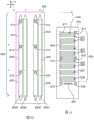
图2和图3是分别示出根据一个实施方式的对样品202成像的透视图和侧横截面视图的图示。在所示实施方式中,样品202包括被表示为流动池的光学基底204。然而,在可选实施方式中,样品202可以包括如上所述的微阵列。如所示,光学基底204可以包括第一板或层206和第二板或层208,具有在第一层206和第二层208之间延伸的内部容积或通道210。内部通道210可以被配置成允许试剂通过其的流动。第一层206和第二层208可以由各种基底材料形成。基底材料可以对入射光的波长和从样品提供的光信号实质上是透明的。例如,基底材料可以对由样品中的一个或更多个标记发射的光信号实质上是透明的,或者可以对被样品反射或折射的光信号实质上是透明的。第一层206和第二层208可以在其相应的内表面216和218上分别具有生物组分212和214。2 and 3 are diagrams showing perspective and side cross-sectional views, respectively, of imaging a
在各种实施方式中,样品202可以沿着线性聚焦区222(也被称为辐射线)被激发光或辐射220照射。然而,在其他实施方式中,聚焦区可以具有其他配置(例如点、椭圆形)。聚焦区222可以通过物镜224由来自一个或更多个激发光源的激发辐射220形成。激发光源可以生成被处理和成形以在样品202上提供聚焦区222的光束。聚焦的光束可以包括具有激发生物组分212和214的相关联的荧光团的不同发射光谱的光信号。当被激发时,荧光团发射可能具有不同发射光谱的光信号。在一些实施方式中,光学系统可以首先将激发辐射220引导到光学基底204的内表面216以照射生物组分212。此外,光学基底204和物镜224可以以相对于彼此的相对方式移动,使得样品202在如箭头226所指示的方向上平移。因此,聚焦区222可沿着内表面216逐渐照射生物组分。当聚焦区222沿内表面216平移时,聚焦的光束可以连续地扫描区228,从而扫描光学基底204的整个内表面216。在扫描内表面216之后,物镜224和样品202可以相对于彼此移动,并且相同的过程可以重复以扫描光学基底204的内表面218。In various embodiments, the
在特定实施方式中,装置或方法可以以至少约0.01mm2/秒的速率检测表面上的特征。根据特定应用,还可以使用更快的速率,包括例如在被扫描或以其他方式检测的区域上至少约0.02mm2/秒、0.05mm2/秒、0.1mm2/秒、1mm2/秒、1.5mm2/秒、5mm2/秒、10mm2/秒、50mm2/秒、100mm2/秒或更快的速率。例如,如果需要,为了降低噪音,检测速率可以具有约0.05mm2/秒、0.1mm2/秒、1mm2/秒、1.5mm2/秒、5mm2/秒、10mm2/秒、50mm2/秒或100mm2/秒的上限。In certain embodiments, a device or method can detect features on a surface at a rate of at least about 0.01 mm2 /sec. Depending on the particular application, faster rates may also be used, including, for example, at least about 0.02 mm2 /sec, 0.05 mm2 /sec, 0.1 mm2 /sec, 1 mm2 /sec, 1.5mm2 /sec, 5mm2 /sec, 10mm2 /sec, 50mm2 /sec, 100mm2 /sec or faster rate. For example, if desired, in order to reduce noise, the detection rate can be of about 0.05mm2 /sec, 0.1mm2 /sec, 1mm2 /sec, 1.5mm2 /sec, 5mm2 /sec, 10mm2 /sec, 50mm2 /sec seconds or an upper limit of 100mm2 /sec.
在一些实施方式中,生物材料可以固定在光学基底204的多个表面上。例如,图3示出了具有分别附着到内表面216和218的生物组分212和214的光学基底204。在所示实施方式中,附着层230可以在两个内表面216和218上形成。附着层230可便于将生物组分212和214固定在其上。如所示,可以使用第一激发辐射232来照射在光学基底204的内表面216上的生物组分212。来自被照射的生物组分212的光发射234可以通过层206返回。同时或顺序地,可以使用第二激发辐射236来照射在光学基底204的内表面218上的生物组分214。光发射238可以从所照射的生物组分214通过通道210和层206返回。In some embodiments, biomaterials can be immobilized on multiple surfaces of the
在特定实施方式中,当通过具有高数值孔径(NA)值的物镜对样品成像时,可以使用路径补偿器。示例性的高NA范围包括至少约0.6的NA值。例如,NA值可以为至少约0.65、0.7、0.75、0.8、0.85、0.9、0.95或更高。本领域中的技术人员将认识到,根据透镜在其中工作的介质的折射率,NA可以更高,包括例如对于空气高达1.0、对于纯水为1.33或对于其他介质(诸如油)更高。补偿器也可以在具有比上面列出的示例更低的NA值的物镜中得到使用。通常,物镜的NA值是角度的宽度的度量,物镜可以对该角度接收光。对于给定的固定放大率,NA值越高,可由物镜收集的光就越多。作为结果,当使用具有较高NA值的物镜时,可以更容易地区分多个物体,因为较高的特征密度也许是可能的。In certain embodiments, a path compensator may be used when imaging a sample through an objective with a high numerical aperture (NA) value. Exemplary high NA ranges include NA values of at least about 0.6. For example, the NA value can be at least about 0.65, 0.7, 0.75, 0.8, 0.85, 0.9, 0.95 or higher. Those skilled in the art will recognize that the NA can be higher depending on the refractive index of the medium in which the lens operates, including, for example, up to 1.0 for air, 1.33 for pure water, or higher for other media such as oil. Compensators can also be used in objectives with lower NA values than the examples listed above. In general, the NA value of an objective is a measure of the width of the angle at which the objective can receive light. For a given fixed magnification, the higher the NA value, the more light can be collected by the objective. As a result, multiple objects can be more easily distinguished when using objectives with higher NA values, since higher feature densities may be possible.
图4示出了可以在不同成像会话期间使用的光学系统250的不同光学配置281-283。光学系统250包括具有聚光端294的物镜256。还示出,载体组件260定位成靠近物镜256的聚光端294。载体组件260可以包括第一基底252A或第二基底252B。在示例性实施方式中,第一基底252A是流动池,而第二基底252B是开放面基底。如将在下面更详细描述的,本文描述的实施方式包括可调整或可修改的光学系统和组件。例如,可以针对不同的成像会话改变影响由样品提供的光信号的光学部件的共同布置。改变光学部件的共同布置引起来自样品的光信号的传播的变化或在检测到的光信号的光谱中的变化。可以通过移除或重新定位一个或更多个光学部件来修改共同布置。此外,可以通过沿光路交换滤波器来修改共同布置,使得不同的光信号被检测器组件检测。Figure 4 shows different optical configurations 281-283 of the
如所示,工件距离WD可以存在于样品252A和物镜256的聚光端294之间。在一些实施方式中,工作距离WD小于约5000微米。在特定实施方式中,工作距离WD小于约2000微米,且更特别地小于约1000微米。As shown, the workpiece distance WD may exist between the
在图4中,载体组件260包括用于支撑第一和第二基底252A和252B的同一支撑框架262。当支撑第二基底252B时,载体组件260还可以包括接装板(未示出)。在示例性实施方式中,第一基底252A包括具有至少部分地由第一和第二材料层限定的流动通道的流动池。光信号从流动通道内的标记通过一个或更多个层和可能的流体传播到流动池的外表面。然后光信号从外表面传播到物镜。然而,第二基底252B可以是开放面基底,使得标记位于开放面基底的相应外表面附近并从其提供光信号。在一些情况下,由于第一和第二基底252A、252B的结构,从第一和第二基底252A、252B的标记发射的光信号在到达物镜256之前将不同地被影响。因此,本文描述的实施方式可以改变光学系统的共同布置,使得可以适当地检测光信号。In Figure 4, the
图4中所示的不同光学配置281-283表示路径补偿器293和295可如何被选择性地移动以提供不同的共同布置的特定示例。路径补偿器293和295调整由样品提供的光信号的光路。在各种实施方式中,可以选择性地移动光学部件,使得路径补偿器295可以位于第二基底252B和物镜256之间,和/或路径补偿器293可以位于相对于物镜256的焦外位置上。The different optical configurations 281-283 shown in Figure 4 represent specific examples of how the path compensators 293 and 295 can be selectively moved to provide different co-arrangements.
如所示,光学配置281包括物镜256,而没有位于焦外位置上或在物镜256与第一基底252A之间的任何光学部件(例如路径补偿器)。作为示例,光学配置281可以在成像会话间被使用,其中期望对流动池中的流动通道的底表面成像,如图4所示。当对流道的底表面成像时,输入光信号通过流动池的顶层并然后通过在顶层和底层之间限定的空腔传输。在对流动通道的底表面成像之后,测定系统可以移动以对样品的其它表面(例如流动通道的顶表面或流动池的外表面或另一个样品)成像。在这种情况下,光信号不再通过顶层和空腔传输。更具体地,如果测定系统随后对流动通道的顶表面或不同样品的外表面成像,则调整光路或聚焦区以补偿减少的层可能是合乎需要的。As shown,
因此,光学配置282包括相对于物镜256位于焦外位置处的路径补偿器293。路径补偿器293可以由传送设备选择性地移动到焦外位置,诸如与在US 2009/0272914或美国专利号8,481,903中描述的传送设备相似的传送设备,这两个专利每个通过引用被并入本文。可以在成像会话期间使用光学配置282,其中期望的是对在流动池中的流动通道的顶表面成像。Accordingly,
光学配置283包括位于物镜256的聚光端294与在成像位置处的第二基底252B之间的路径补偿器295。在成像位置上,路径补偿器295和聚光端294可以彼此间隔开固定距离。然而,路径补偿器295和第二基底252B可以间隔开可调整的距离。更具体地,第二基底252B和物镜256可以在成像会话期间朝向彼此移动或远离彼此移动。
路径补偿器295可以通过传送设备选择性地移动到成像位置。在成像会话期间,路径补偿器295可以具有相对于物镜256的固定位置。在一些实施方式中,路径补偿器295通过一个或更多个中间部件可操作地耦合到物镜256。在可选实施方式中,路径补偿器295直接附接到物镜256的聚光端294。光学配置283可以用于扫描例如微阵列的外表面。The path compensator 295 can be selectively moved to the imaging position by the transfer device. The path compensator 295 may have a fixed position relative to the
图5为了演示对于至少一些光学部件的功能布置的目的而示出示例性测微荧光计的分解图。显示了两个激发源,包括绿色LED(LEDG)和红色LED(LEDR)。来自每个激发源的激发光分别通过绿色LED聚光透镜L6和红色LED聚光透镜L7。LED折叠镜M1将绿色激发辐射反射到组合器二向色镜F5,其通过激发滤波器F2、然后通过激光二极管分束器F3、然后通过激发场挡块FS、然后通过激发投影透镜组L2到激发/发射二向色镜F4,其通过静止物镜组L3和平移物镜组L4将绿色激发辐射反射到流动池FC的表面。红色激发辐射从红色LED聚光透镜L7传递到组合器二向色镜F5,其后红色激发辐射遵循与绿色激发辐射到流动池FC的表面的相同的路径。如图所示,通过使平移物镜组L4上下移动(即沿Z维度)来启动聚焦。来自流动池FC表面的发射通过平移物镜组L4且然后通过静止物镜组L3传递回到激发/发射二向色镜F4,其将到发射辐射传递到发射投影透镜组L1直到发射滤波器,且然后到CMOS图像传感器S1。激光二极管LD也经由激光二极管耦合透镜组L5被引导到激光二极管分束器F3,该激光二极管分束器F3通过激发场挡块FS、激发投影透镜组L2、激发/发射二向色镜F4、静止物镜组L3和平移物镜组L4将激光二极管辐射反射到流动池FC。5 shows an exploded view of an exemplary microfluorometer for the purpose of demonstrating the functional arrangement for at least some optical components. Two excitation sources are shown, including a green LED (LEDG) and a red LED (LEDR). The excitation light from each excitation source passes through the green LED condenser lens L6 and the red LED condenser lens L7, respectively. LED fold mirror M1 reflects green excitation radiation to combiner dichroic mirror F5, which passes through excitation filter F2, then through laser diode beam splitter F3, then through excitation field stop FS, and then through excitation projection lens set L2 to Excitation/emission dichroic mirror F4, which reflects green excitation radiation to the surface of flow cell FC through stationary objective group L3 and translating objective group L4. The red excitation radiation passes from the red LED condenser lens L7 to the combiner dichroic mirror F5, after which the red excitation radiation follows the same path as the green excitation radiation to the surface of the flow cell FC. Focusing is initiated by moving the translating objective group L4 up and down (ie, along the Z dimension) as shown. Emission from the surface of flow cell FC passes back to excitation/emission dichroic mirror F4 through translating objective set L4 and then through stationary objective set L3, which passes the incoming emission radiation to emitting projection lens set L1 up to the emission filter, and then to the CMOS image sensor S1. The laser diode LD is also directed via the laser diode coupling lens group L5 to the laser diode beam splitter F3, which passes through the excitation field stop FS, the excitation projection lens group L2, the excitation/emission dichroic mirror F4, The stationary objective group L3 and the translating objective group L4 reflect the laser diode radiation to the flow cell FC.
如图5的示例性实施方式所证明的,测微荧光计中的每一个可以包括分束器和检测器,其中分束器被定位成将激发辐射从激发辐射源引导到物镜并且将发射辐射从物镜引导到检测器。每个测微荧光计可以可选地包括诸如LED的激发辐射源。在这种情况下,每个测微荧光计可以包括专用辐射源,使得读取头包括几个辐射源,每个辐射源分离到单独的测微荧光计内。在一些实施方式中,两个或更多个测微荧光计可以接收来自公共辐射源的激发辐射。因此,两个或更多个测微荧光计可共享辐射源。在示例性配置中,单个辐射源可以将辐射引导到分束器,该分束器被定位成将激发辐射分离成两个或更多个光束并且将光束引导到两个或更多个相应的测微荧光计。此外或可选地,激发辐射可以经由一个或更多个光纤从辐射源被引导到一个、两个或更多个测微荧光计。As demonstrated by the exemplary embodiment of FIG. 5, each of the microfluorometers may include a beam splitter and a detector, wherein the beam splitter is positioned to direct excitation radiation from the excitation radiation source to the objective and emit radiation Guide from the objective lens to the detector. Each microfluorometer may optionally include an excitation radiation source such as an LED. In this case, each microfluorometer may include a dedicated radiation source, such that the readhead includes several radiation sources, each separated into a separate microfluorometer. In some embodiments, two or more microfluorometers may receive excitation radiation from a common radiation source. Thus, two or more microfluorometers can share the radiation source. In an exemplary configuration, a single radiation source may direct radiation to a beam splitter positioned to split excitation radiation into two or more beams and direct the beams to two or more corresponding beams Microfluorometer. Additionally or alternatively, excitation radiation may be directed from the radiation source to one, two or more microfluorometers via one or more optical fibers.
将理解,附图中所示的特定部件是示例性的,并且可以用具有类似功能的部件替换。例如,可以使用各种辐射源中的任一种来代替LED。特别有用的辐射源是弧光灯、激光器、半导体光源(SLS)或激光二极管。LED可以从例如Luminus(马萨诸塞州的比尔里卡)购买。类似地,各种检测器是有用的,包括但不限于电荷耦合器件(CCD)传感器、光电倍增管(PMT)、或互补金属氧化物半导体(CMOS)传感器。一个特别有用的检测器是从AptinaImaging(加利福尼亚州的圣何塞)可得到的5兆像素CMOS传感器(MT9P031)。It will be understood that certain components shown in the figures are exemplary and may be replaced with components having similar functions. For example, any of a variety of radiation sources may be used in place of LEDs. Particularly useful radiation sources are arc lamps, lasers, semiconductor light sources (SLS) or laser diodes. LEDs can be purchased, for example, from Luminus (Billerica, MA). Similarly, various detectors are useful, including but not limited to charge coupled device (CCD) sensors, photomultiplier tubes (PMT), or complementary metal oxide semiconductor (CMOS) sensors. A particularly useful detector is a 5 megapixel CMOS sensor (MT9P031) available from Aptina Imaging (San Jose, CA).
图5提供了包括两个激发源的测微荧光计的示例性实施方式。该配置对于检测分别在不同波长处激发的至少两个荧光团是有用的。如果需要,测微荧光计可以被配置成包括多于两个激发源。例如,测微荧光计可以包括至少2个、3个、4个或更多个不同的激发源(即,从彼此产生不同波长的源)。可选地或另外,分束器和光学滤波器可以用于扩大从单个辐射源可获得的激发波长的范围。对于其中几种测微荧光计共享来自一个或更多个辐射源的激发的实施方式,可以使用多个辐射源的类似使用和/或分离激发光束的光学滤波。如在本文其他地方进一步详细阐述的,多个激发波长的可用性对于利用几种不同荧光团标记的测序应用特别有用。Figure 5 provides an exemplary embodiment of a microfluorometer including two excitation sources. This configuration is useful for detecting at least two fluorophores that are excited at different wavelengths, respectively. If desired, the microfluorometer can be configured to include more than two excitation sources. For example, a microfluorometer can include at least 2, 3, 4, or more different excitation sources (ie, sources that generate different wavelengths from each other). Alternatively or additionally, beam splitters and optical filters can be used to expand the range of excitation wavelengths obtainable from a single radiation source. For embodiments in which several microfluorometers share excitation from one or more radiation sources, similar use of multiple radiation sources and/or optical filtering to separate excitation beams may be used. The availability of multiple excitation wavelengths is particularly useful for sequencing applications that utilize several different fluorophore labels, as elaborated further elsewhere herein.
图6示出了在单个读取头或承载器300中的四个测微荧光计的示例性布置。四个测微荧光计相对于流动池306的第一和第二通道302和304布置在交错布局中。在所示的布置中,测微荧光计中的两个(对应于检测器310A和310C)被配置成对第一通道302的分离区成像,而其它两个测微荧光计(对应于检测器310B和310D)被配置成对第二通道304的分离区域成像。如所示,测微荧光计(对应于检测器310A和310C)在x维度上相对于测微荧光计(对应于检测器310B和310D)交错,使得两对测微荧光计可以分别检测相邻的第一和第二通道302和304。测微荧光计每个具有正交的发射和激发路径,辐射源312位于读取头的与流动池306相对的同一侧上。检测器310A和310C中的两个位于读取头的第一侧上,而其它两个检测器310B和310D位于相对侧上,这两侧都与激发源所位于的那侧正交。在图6所示的示例性实施方式中,四个辐射源与单个大型散热器314热接触。与使用对于每个辐射源的单独散热器的许多配置相比,单个大型散热器提供更大程度的散热。然而,如果需要,单独辐射源可以热耦合到单独散热器。图6所示的测微荧光计的布置的优点是紧凑的读取头的提供。对于其中在每个测微荧光计中的激发源和检测器的相对位置被互换的实施方式,可以得出类似的优点,FIG. 6 shows an exemplary arrangement of four microfluorometers in a single readhead or
图6所示的读取头300被定位成在y维度上扫描。y维度与流动池306的长度平行,使得读取头300在扫描操作中的移动将导致沿着流动池306的长度的区域的成像。检测器310A-310D位于读取头300的相对侧上,并且在流动池306的相对侧上,流动池的侧面沿扫描方向延伸。读取头300相对于流动池306和扫描方向的定向仅是示例性的,并且其他定向可以被使用。The
测微荧光计或具有几个测微荧光计的读取头可以位于流动池上方(相对于重力的箭头),如对本文所阐述的几个实施方式所例示的。然而,也可能在流动池下方定位测微荧光计或读取头。因此,相对于所使用的激发和发射辐射的波长,流动池在顶侧、底侧或两侧上可以是透明的。实际上,在一些实施方式中,将测微荧光计定位在流动池的两侧上或者将读取头定位在流动池的两侧上可能是合乎需要的。相对于重力的其它定向也是可能的,包括例如在流动池和测微荧光计(或读取头)之间的并排定向。A microfluorometer or a readhead with several microfluorometers can be positioned above the flow cell (arrows relative to gravity), as exemplified for several embodiments set forth herein. However, it is also possible to position the microfluorometer or readhead below the flow cell. Thus, the flow cell can be transparent on the top side, bottom side or both sides with respect to the wavelengths of excitation and emission radiation used. Indeed, in some embodiments, it may be desirable to position the microfluorometer on both sides of the flow cell, or position the readheads on both sides of the flow cell. Other orientations with respect to gravity are also possible, including, for example, a side-by-side orientation between the flow cell and the microfluorometer (or readhead).
测微荧光计或读取头可被配置为从流动池的单侧检测流动池的两个相对的内表面。例如,测微荧光计或读取头可以使用被插入和移除的光学补偿器来检测流动池的可选表面。用于检测流动池的相对内表面的示例性方法和装置(诸如光学补偿器的使用)在通过引用被全部并入本文的美国专利号8,039,817中被描述。补偿器是可选的,例如取决于装置的NA和/或光学分辨率。The microfluorometer or readhead can be configured to detect two opposing inner surfaces of the flow cell from a single side of the flow cell. For example, a microfluorometer or readhead can use an optical compensator that is inserted and removed to detect select surfaces of the flow cell. Exemplary methods and apparatus for detecting opposing inner surfaces of a flow cell, such as the use of optical compensators, are described in US Pat. No. 8,039,817, which is incorporated herein by reference in its entirety. The compensator is optional, eg depending on the NA and/or optical resolution of the device.
图7是被配置成接纳载体组件(诸如载体组件400和500(分别为图8和图12))的系统台320的一部分的透视图。系统台320包括具有基面322和沿基面322定位的多个基准324-326的台主体或平台321。基准324-326相对于基面322具有固定位置。在图7中,台主体321是块形的,但是应当理解,可以使用各种形状。基面322成形为与基底和/或载体组件相连接。例如,基面322的至少一部分可以是平面的,用于与流动池相连接。在一些实施方式中,基面322配置成朝着或远离载体组件的基底传递热能。更具体地,基面322可以热耦合到热循环仪。作为示例,当流动池被载体组件保持并位于基面322上时,基面322可以朝着流动池传导热或者从流动池吸收热。在所示实施方式中,与载体组件相连接的基面322是平面的。然而,在其它实施方式中,基面322可以是非平面的。例如,基面322可以成形为补充载体组件的形状。7 is a perspective view of a portion of system table 320 configured to receive carrier assemblies, such as
基准324-326被配置为提供接合基底的固定参考点或表面,用于将基底保持在相对于光学系统或更特别地物镜的固定位置上。在所示的实施方式中,基准324-326是从基面322延伸的圆柱形突出部(例如柱),但是在可选实施方式中基准324-326可以具有其他形状。基准324-326相对于彼此和基面322的位置可以基于载体组件的设计、基底(例如流动池)的形状和/或接装板的形状。The fiducials 324-326 are configured to provide fixed reference points or surfaces to engage the substrate for holding the substrate in a fixed position relative to the optical system or, more particularly, the objective lens. In the embodiment shown, the fiducials 324-326 are cylindrical protrusions (eg, posts) extending from the
还示出,系统台320(或对接系统)可以包括被配置成接合载体组件和/或基底的对准机构330。在所示实施方式中,对准机构330包括可移动臂332,该可移动臂配置成围绕轴333旋转。可移动臂332可操作地连接到被配置成驱动可移动臂332的马达334。基准324-326和可移动臂332通常在其间限定基面322的载体接纳区域336。载体接纳区域336被配置成使载体组件位于其上。当载体组件位于载体接纳区域336上时,马达334可以朝着载体组件驱动可移动臂332。可移动臂332可以接合载体组件并将载体组件推向基准324-326。Also shown, the system stage 320 (or docking system) may include an
在所示实施方式中,可移动臂332被旋转。然而,在其他实施方式中,可移动臂332可以以其他方式移动。例如,可移动臂332可以以线性方式移动。在一些实施方式中,使可移动臂332移动以接合载体组件的单个冲程可以包括在多个方向上的运动。例如,可移动臂332可以最初在第一线性方向上移动,且然后在第二线性方向上移动或在另一方向上旋转。在其它实施方式中,可使用多于一个对准机构。此外,还可以使用可选方法来将载体组件保持在指定位置上。例如,气动泵可以使用气体(例如环境空气)来以指定的方式推动或拉动载体组件。In the embodiment shown, the
图7中还示出,系统台320可以包括多个歧管口340。歧管口340被配置为与基底的端口(诸如流动池的端口)对准。可以通过歧管口340提供或抽出流体。Also shown in FIG. 7 , the
图8是根据一个实施方式的载体组件400的透视图。载体组件400配置成在其中来自基底的光信号被检测的成像操作期间保持样品。载体组件400可以与诸如图1的测定系统100的测定系统一起使用,并且位于诸如系统台320(图7)的系统台上。载体组件400包括支撑框架402。支撑框架402包括具有第一和第二主体侧408、410的框架主体404。第一主体侧408被配置为面向诸如物镜256的光学系统的物镜。第二主体侧410被配置为与诸如系统台320(图7)的系统台相连接。FIG. 8 is a perspective view of a
支撑框架402可以限定样品区406。在一些实施方式中,样品区406包括接装板420。在其他实施方式中,样品区406包括完全在第一和第二主体侧408、410之间延伸的打开的窗口或一个或更多个通孔。在一些实施方式中,样品区406是完全通过框架主体404延伸的窗口,使得窗口通过主体侧408、410中的任一个可进入。接装板420可以位于窗口内并且耦合到支撑框架402。接装板420可以阻挡窗口的全部或大部分。在一些实施方式中,接装板420和支撑框架402形成一个连续结构。在其他实施方式中,接装板420可移除地耦合到支撑框架402。在可选实施方式中,接装板420不是载体组件400的一部分。例如,在SBS方案期间,载体组件400可以仅包括具有位于样品区406内的流动池的支撑框架402。在微阵列成像方案期间,载体组件400可以包括接装板420和诸如珠芯片的开放面基底。The
框架主体404还包括内框架边缘412和外框架边缘414。在一些实施方式中,内框架边缘412可以限定样品区406。外框架边缘414限定框架主体404的周边,并且被配置为接合对接系统(未示出)的对准特征。对准特征可以包括例如对准机构,诸如对准机构330(图7)。框架主体404具有在第一和第二主体侧408、410之间测量的厚度416。支撑框架402被配置为位于系统台上,并且允许物镜在成像操作期间沿着指定路径在支撑框架402旁边移动。如本文所使用的,当物镜和/或系统台被移动时,物镜可以“移动”,使得期望被成像的物体相对于物镜移动。在所示实施方式中,厚度416实质上是均匀的,使得框架主体404实质上是平面的。在其他实施方式中,框架主体404可以包括非平面特征。非平面特征可以位于物镜的指定路径的外部。The
也在图8示出,接装板420具有板主体421。接装板420位于样品区406内。在所示实施方式中,接装板420覆盖样品区406的全部,除了接装板420的通路或通孔422以及孔464、465、466之外。在一些实施方式中,接装板420的至少一部分可以在第二主体侧410旁边延伸或接合第二主体侧410。板主体421包括内板边缘424。内板边缘424限定接装板420的接收部426。板主体421还可以包括在接收部426内的基底或芯片平台428。芯片平台428具有平台表面430,其被配置为具有位于其上的基底。板主体421还包括凹部432。在所示实施方式中,凹部432围绕平台428的大部分。Also shown in FIG. 8 , the
图8中还示出,载体组件400可包括保持机构418。保持机构418可以耦合到接装板420和/或框架主体404。保持机构418配置成接合位于接收部426内的基底,以将基底保持在接收部426中的固定位置。保持机构418包括可移动基准块440。在示例性实施方式中,基准块440是弹簧承载的,使得基准块440可以被偏转或移动到压缩状态,且然后被释放以接合在接收部426内的基底(未示出),并将基底保持在接收部426内。Also shown in FIG. 8 ,
图9是具有位于接装板420的接收部426内的基底434的载体组件400的平面图。基底434由保持机构418保持。更具体地,保持机构418的基准块440施加将基底边缘438压靠在内板边缘424上的保持力436。在与XY平面平行的方向上施加保持力436。因此,基底434相对于接装板420保持在固定位置上。在其他实施方式中,可以至少部分地在垂直于XY平面的方向上施加保持力436,使得基底434被压靠在接装板420上。例如,基底434可被压靠在平台表面430上(图8)。FIG. 9 is a plan view of the
在一些实施方式中,接装板420可以相对于框架主体404沿XY平面可移动。例如,接装板420可以包括被配置为面向内框架边缘412的外板边缘442。在一些情况下,外板边缘442可以表示接装板420的最外边缘。然而,在其他情况下,外板边缘442不是接装板420的最外边缘。例如,板主体421的一部分可以在框架主体404下方(如图9所示)和在主体侧410旁边(图8)延伸。如图9所示,外板边缘442和内框架边缘412可以分开公差间隙444和公差间隙446。公差间隙444具有沿X轴测量的距离,而公差间隙446是沿着Y轴测量的距离。In some embodiments, the
然而在其他实施方式中,接装板420可以具有相对于框架主体404的固定位置。在特定实施方式中,接装板420和框架主体404可以被模制在公共模具内,使得框架主体404和接装板420是单一材料块的一部分。可选地,框架主体404和接装板420可以是在相对于彼此的固定位置上固定到每个的分立部件。In other embodiments, however, the
在图9中还示出,通路422位于基底边缘438周围。通路422至少部分地限定在接装板420的边缘和基底边缘438的一部分之间。通路422被依尺寸制造和成形以允许个体的指头(例如,手指)的一部分插入其中并且接合基底边缘438以用于加载或移除基底434。接装板420的通路422被定位成使得个体在抓住基底434时可以将基底434定位在接收部426内。例如,通路422A可以接纳食指或拇指的尖端,并且当基底434位于接收部426内时,通道422B可以接纳拇指或食指的尖端。在定位操作期间,保持机构418可以被启动、被压缩以将基准块440远离接收部426移动。当基底434位于接收部426内或者在基底434位于接收部426中之后,基准块440可以被释放,使得基准块440可以朝着基底434移回并接合基底边缘438。如所示,基底434是在其上具有微阵列448的开放面基底。在其他实施方式中也可以使用其它类型的基底434。Also shown in FIG. 9 , the
图10是具有位于样品区406内的基底450的载体组件400的平面图。基底450可以是具有一个或更多个流动通道的流动池。例如,在所示实施方式中,流动池450具有在流动池450的流动池主体460内形成的四个流动通道452。每个流动通道452具有在第一端口454和第二端口456之间延伸的成像段458。第一和第二端口454、456是流动池主体460中的开口或孔。在所示实施方式中,第一端口454是入口,而第二端口456是出口。然而,在其他实施方式中,第一端口454可以是出口,而第二端口456可以是入口。还示出,流动通道452是线性的,并且流动通道452的成像段458彼此平行地延伸。然而,在其他实施方式中,流动通道452可以沿着非线性路径延伸和/或可以相对于彼此在非平行方向上延伸。FIG. 10 is a plan view of
在所示实施方式中,接装板420从样品区406移除。框架主体404或可选的接装板(未示出)可以包括延伸到样品区406中并为流动池450提供搁置表面的元件(未示出),使得框架主体404防止流动池450通过样品区406。流动池主体460包括外主体边缘462。外主体边缘462配置成与框架主体404的内框架边缘412的至少一部分接合。在一些实施方式中,流动池450可以相对于内框架边缘412被依尺寸制造并成形,使得流动池450可以在样品区406内沿着XY平面可移动。In the illustrated embodiment, the
参考图9和图10,框架主体404包括孔464、465、466。在样品区406包括窗口的一些实施方式中,孔464-466向窗口敞开。孔464-466被依尺寸制造并成形为接纳系统台(未示出)的相应的基准474、475、476。孔464-466通过第二主体侧410接纳相应的基准474-476。基准474-476可以与基准324-326(图7)相似或相同。基准476被配置成停止接装板420或者可选地流动池沿着Y轴的运动。基准474、475被配置为停止接装板420或者可选地流动池沿X轴的运动。孔464-466被依尺寸制造成大于相应的基准474-476,以允许框架主体404在定位操作期间沿基面滑动。因此,基准474-476被配置成在指定位置对准流动池450,或者可选地在指定位置对准接装板420以及因此对准基底434。在指定位置上,流动池450可以定位成用于成像并用于使流动通道452与系统台(未示出)的歧管口对准。流动池450的第一和第二端口454、456中的每一个可以与相应的歧管口对准。在指定位置上,基底434不流体地耦合到相应的歧管口中的任一个。在一些实施方式中,基底434和/或接装板420可以密封歧管口。Referring to FIGS. 9 and 10 , the
为了将基底450定位在系统台上,基底450可以位于样品区406或窗口内。样品区406可以依尺寸被制造为大于基底450,以允许基底450沿着XY平面的一些移动。基底450可以接合框架主体404的一个或更多个表面,其防止基底450通过窗口406自由地移动。当载体组件400位于系统台上时,基准474-476可以前进通过相应的孔464-466。诸如对准机构330(图7)的对准机构可以被启动以沿着XY平面移动框架主体404。更具体地,可移动臂可以接合外框架边缘414并且提供使框架主体404沿着XY平面移动(例如移位)的对准力437。当框架主体404沿着XY平面移动时,基底450接合基准474-476,并且防止基底450沿着XY平面移动得更远。框架主体404可以相对于基底450移动,直到基底450接合内框架边缘412为止并防止框架主体404移动得更远。因此,基底450可以具有相对于物镜的指定位置以用于检测光信号。To position the
为了将基底434定位在系统台上,接装板420可以位于框架主体404的样品区406内。例如,接装板420可以耦合到第二主体侧410(图8),使得接装板420的一部分设置在窗口406内。在接装板420定位在样品区406内之前或者在接装板420定位在样品区406内之后,基底434可以被装入到接收部426中。例如,图11示出了载体组件400的一部分,其中基底434与基准块440接合并保持在接收部426内。基准块440位于至少部分地由内板边缘424限定的保持凹部480内。基准块440包括延伸到接收部426中的接合表面482,并被配置成与其中的基底434接合。基准块440被配置为相对于接收部426或接装板420移动,以允许基底434自由地定位在接收部426内。例如,可以按压基准块440,使得接合表面482位于板主体421内,而不位于接收部426内。当基底434被装入接收部426中时或者在基底434被装入接收部426之后,基准块440可以被释放以允许接合表面482接合基底边缘438。接合表面482可以被成形使得基准块440沿着Y轴推进基底434。基底434可以保持在基准块440和内板边缘424的一部分之间。在示例性实施方式中,保持机构418包括将基准块440保持在偏置位置上的弹簧。然而,可以使用可选的保持机构。In order to position the
返回到图9,当基底434位于接装板420内并由接装板420保持时,载体组件400可以被装到系统台上。当载体组件400位于系统台上时,基准474-476可以前进通过相应的孔464-466。如上所述,可以启动对准机构以沿着XY平面移动框架主体404。当框架主体404沿着XY平面移动时,接装板420接合基准474-476,其阻止接装板420沿着XY平面移动得更远。在一些实施方式中,框架主体404可以相对于接装板420移动,直到接装板420接合内框架边缘412为止并防止框架主体404移动得更远。因此,接装板420可以具有相对于物镜的固定位置,且因此基底434可以具有相对于物镜的指定位置以用于检测光信号。Returning to FIG. 9 , the
如本文所述,在可选实施方式中,接装板420可以相对于框架主体404具有固定位置。例如,接装板420可以可移除地固定到框架主体404,使得接装板420相对于框架主体404不移位或移动。可选地,框架主体404和接装板420可以是相同单一结构的一部分。As described herein, in alternative embodiments, the
图12是根据实施方式的载体组件500的透视图。载体组件500可以包括与载体组件400(图8)相似或相同的特征和元件。载体组件500可以与测定系统(诸如图1的测定系统100)一起使用。载体组件500包括支撑框架502。支撑框架502包括限定样品区506的框架主体504。框架主体504包括第一和第二主体侧508、510。在所示实施方式中,样品区506形成用于接纳基底的接收部或空间。还示出,框架主体504的内框架边缘512限定框架主体504的向样品区506敞开的孔564、565和566。孔564-566被依尺寸制造和成形以接纳用于在定位操作期间对准流动池的基准(未示出)。FIG. 12 is a perspective view of a
框架主体504包括内框架边缘512和还有外框架边缘514。内框架边缘512可以限定样品区506。外框架边缘514限定框架主体504的周边,并且被配置为接合光学系统的对准特征(未示出)。载体组件500包括具有板主体521的接装板520。在所示实施方式中,接装板520位于样品区506内。接装板520跨越整个样品区506,除了通路或通孔522和孔564-566之外。
在一些实施方式中,接装板520和支撑框架502是分立部件。在这样的实施方式中,接装板520的至少一部分可以在框架主体504的第二主体侧510旁边延伸或接合框架主体504的第二主体侧510。板主体521包括内板边缘524。内板边缘524限定接装板520的接收部526。板主体521还包括在接收部526内的基底或芯片平台528。芯片平台528包括平台表面530,其被配置为具有位于其上的基底534。板主体521还包括凹部532。In some embodiments, the
图12中还示出,接装板520包括耦合到板主体521的保持机构518。保持机构518配置成当基底534位于接收部526内时接合基底534以将基底534保持在相对于接装板520的固定位置上。保持机构518包括可操作地耦合到弹簧541的可移动基准块540。弹簧541配置成沿着Y轴推进基底534,以将基底534保持在基准块540和内板边缘524之间。在所示实施方式中,基准块540可以被拉离接收部526,以允许基底534定位在其中。Also shown in FIG. 12 , the
在一些实施方式中,当基底534位于接装板520上时并且当可以类似于基底450(图10)的流动池位于接装板520上时,接装板520可以耦合到框架主体504。例如,接装板520可以包括流体开口581、582、583和584。流体开口581、582位于接装板520的一端586处,并且流体开口583、584位于接装板520的相对端588处。流体开口583、584位于保持机构518的相对侧上。流体开口581-584允许歧管(或系统台)的歧管口(未示出)进入流动池。例如,喷嘴可以穿过流体开口581-584延伸并且接合流动池的端口。In some embodiments, the
图13是位于系统台550上的载体组件500的平面图。系统台550包括从系统台550的基面578突出的多个基准574-576。支撑框架502的第二主体侧510(图12)接合基面578。在成像操作期间,第一主体侧508面向物镜(未示出)。支撑框架502的孔564-566向第二主体侧510敞开并且从第二主体侧510朝着第一主体侧508延伸。在所示实施方式中,孔564-566完全延伸穿过支撑框架502。然而,在其他实施方式中,孔564-566可以是仅部分地延伸到支撑框架502中的凹部。孔564-566接纳相应的基准574-576。FIG. 13 is a plan view of
在一些实施方式中,接装板520相对于框架主体504可移动(例如可滑动)。在其他实施方式中,接装板520相对于框架主体504具有固定位置。当载体组件500位于系统台上时,流体开口还可以接纳歧管的喷嘴。如所示,接收部526位于中心,使得流体开口581、582和流体开口583、584位于接收部526的相对端上。然而,接收部426(图8)不位于中心。相反,接收部426定位成比另一侧更靠近一侧。接收部426比接收部526定位成更远离对应的基准。在图13中还示出,基准块576可以接合基准块540。在示例性实施方式中,基准块576可以便于将基准块540压入基底534内。基底534可以保持在基准块540和内板边缘524的一个或更多个部分之间。In some embodiments, the
图14A是载体组件500的一部分的横截面,其更详细地示出了样品区506和接收部526。如所示,接装板520耦合到支撑框架502并且位于样品区506内。内框架边缘512限定位于接装板520上方并且在接收部526上方的基底接纳凹部542(由虚线矩形框指示)。基底接纳凹部542被依尺寸制造和成形以接纳第一平面基底,诸如流动池450。内板边缘524限定接收部526。接收部526被依尺寸制造和成形以接纳基底534,该基底534也是平面的并且依尺寸被制造成小于第一平面基底。接收部526至少部分地存在于基底接纳凹部542的下方。在一些实施方式中,接收部526是下列情况中的至少之一:与和内框架边缘512相交的接纳平面546重合或位于接纳平面546下方。在所示实施方式中,接收部526位于接纳平面546的下方。接纳平面546平行于由X和Y轴形成的XY平面延伸。尽管接收部526位于接纳平面546的下方,但是应当理解,在成像操作期间,基底534的一部分可以位于基底接纳凹部542内。14A is a cross-section of a portion of
图14B示出了并排的流动池560和开放面基底570。流动池560具有限定在两个内部通道表面564、566之间的流动通道562。在所示实施方式中,开放面基底570包括特征572(诸如珠)的微阵列,其中每个特征具有指定的地址(在微阵列中的特征当中)和指定的化学物质(例如核酸)。表或数据库可以将每个地址与相应的化学物质相关联。特征572沿着基底表面574定位。Figure 14B shows
本文中阐述的载体组件被配置为保持不同类型的基底,诸如流动池560和开放面基底570,使得要成像的期望表面或区域位于光学系统的成像区580内。成像区580可以表示光学系统能够被聚焦于内的总体平坦的体积。总体平坦的体积可以具有X尺寸、Y尺寸和Z尺寸。X和Y尺寸可以是几毫米或更多。Z尺寸可以在1000微米以内或更小。更具体地,Z尺寸可以是900微米或更小、800微米或更小、700微米或更小、600微米或更小或500微米或更小。在特定实施方式中,Z尺寸可以是400微米或更小、300微米或更小或200微米或更小。在更特定的实施方式中,Z尺寸可以为90微米或更小、80微米或更小、70微米或更小或60微米或更小。在更特定的实施方式中,Z尺寸可以是50微米或更小、40微米或更小、30微米或更小、20微米或更小或10微米或更小。The carrier assemblies set forth herein are configured to hold different types of substrates, such as
在一些实施方式中,基底表面574和内部通道表面564、566中的至少一个能够由载体组件(未示出)定位在成像区580内。载体组件可以与本文所述的载体组件中的任一个相似或相同。因此,可以通过光学系统检查开放面基底570和流动池560中的每一个。如图14B所示,基底表面574和通道表面564是共面的。在其他实施方式中,基底表面574可以与通道表面566共面。在其他实施方式中,基底表面574可以不与任一通道表面共面。基底表面574可以沿着Z轴与对应的通道表面偏移指定的最大量ΔZ。最大量ΔZ可以是例如100微米或更小、90微米或更小、80微米或更小、70微米或更小、60微米或更小、50微米或更小、40微米或更小、30微米或更小、20微米或更小或10微米或更小。然而,在其他实施方式中,偏移的最大量ΔZ可以更大。在所示实施方式中,开放面基底570具有比流动池560的厚度更大的厚度。在其他实施方式中,流动池560的厚度可以大于开放面基底570的厚度。在其他实施方式中,厚度可以是实质上相等的。In some embodiments, at least one of the
图15和图16分别是在下文分别被称为流动池和开放面基底的基底450、434的平面图。流动池450包括沿着Y轴彼此平行地延伸的四个流动通道452A、452B、452C、452D。在可选的实施方式中,可使用更多或更少的流动通道。流动通道452A-452D被对准,使得每个流动通道沿着Y轴在实际上相同的轴向位置处开始和结束。开放面基底434包括微阵列448。微阵列448包括多个阵列区段621-628,其中每个区段包括多个特征条带或通路630。在所示实施方式中,微阵列448包括八(8)个阵列区段,其中每个区段具有五(5)个特征条带。然而,在其他实施方式中,可以使用更多或更少的阵列区段。在其他实施方式中,每个阵列区段可以包括更多或更少的特征条带。在所示实施方式中,阵列区段彼此分离。在其他实施方式中,微阵列448包括一个连续的阵列,而没有单独的阵列区段。15 and 16 are plan views of
图15和图16还分别示出了可以与成像区580类似或相同的成像区600、620。成像区600、620表示三维区,光信号可以分别从流动池450和开放面基底434通过光学系统从该三维区被检测。不同的测定方案可以被配置(例如被编程)以对相应的区成像。在一些实施方式中,成像区表示可由光学系统对相应基底扫描的体积的总和。在特定实施方式中,成像区600可完全与成像区620重叠。在其他实施方式中,成像区600、620可以包括非重叠部分。成像区600、620通常是具有小Z尺寸的平坦区。光学系统可以包括类似于读取头300(图6)的读取头或承载器(未示出)。光学系统可以包括除了别的以外还具有六个物镜(未示出)的六个测微荧光计(未示出)。每个物镜被配置成扫描相应的子区。Figures 15 and 16 also show
如本文所述,一个或更多个不同类型的基底可以保持在光学系统的同一成像区内。例如,具有在系统台上的第一类型的基底的第一载体组件可以用系统台上的第二载体组件替换。第二载体组件可以具有第二类型的基底。可以保持第一和第二载体组件的基底中的每一个,使得相应的样品位于同一成像区内。因此,尽管下文单独地描述成像区600、620,但是应当理解,成像区可以至少部分地彼此重叠。例如,沿着第二基底的样品(例如特征的微阵列)可以位于用于不同的第一基底(例如流动池)的同一成像区内。As described herein, one or more different types of substrates can remain within the same imaging region of the optical system. For example, a first carrier assembly having a substrate of the first type on the system table can be replaced with a second carrier assembly on the system table. The second carrier assembly may have a second type of substrate. Each of the substrates of the first and second carrier assemblies can be held such that the corresponding samples are located within the same imaging zone. Thus, although the
测微荧光计的每个物镜可以具有对应于可以在单个图像中由物镜成像或捕获的区域的视场(FOV)。图15和图16示出了六个FOV 611-616。光学系统被配置为相对于相应的基底移动物镜以获得多个图像。光学系统是傻瓜型光学系统,其中捕获几个不同的图像以覆盖整个成像区。在其他实施方式中,光学系统可以是线扫描或点扫描光学系统。在图15中,FOV611-616中的每个配置成沿第一流动通道的一部分且然后沿着第二流动通道的一部分移动。在成像操作之后,所有四个流动通道可以完全(或接近完全)被成像。在图16中,只有两个FOV 611、612沿微阵列移动以获得微阵列的多个图像。在一些实施方式中,不用于对基底成像的一个或更多个FOV可用于对识别基底的类型的识别码640(例如条形码)成像。Each objective of the microfluorometer can have a field of view (FOV) corresponding to the area that can be imaged or captured by the objective in a single image. Figures 15 and 16 show six FOVs 611-616. The optical system is configured to move the objective relative to the corresponding substrate to obtain a plurality of images. The optics are point-and-shoot optics where several different images are captured to cover the entire imaging area. In other embodiments, the optical system may be a line scan or point scan optical system. In Figure 15, each of the FOVs 611-616 is configured to move along a portion of the first flow channel and then along a portion of the second flow channel. After the imaging operation, all four flow channels can be fully (or nearly fully) imaged. In Figure 16, only two
作为示例,在第一成像操作期间,读取头可以沿着流动池450移动。当读取头相对于系统台移动时,物镜中的每个可以检测来自相应FOV的光信号。如图15所示,成像区600由六个分开的子区601-606形成。子区601-606中的每一个表示可以通过相应的FOV之一成像的成像区600的一部分。例如,读取头可以沿着Y轴移动。FOV 611-613可以获得流动通道452A的多个图像,并且FOV 614-616可以获得流动通道452C的多个图像。在一些实施方式中,读取头可以间歇地暂停,使得当图像被获得时,流动池450和读取头相对于彼此具有实质上固定的位置。在其他实施方式中,读取头可以不暂停,并且可以沿着流动池450连续移动。由于测微荧光计的数量和相应的FOV的位置,流动通道452A和452C的整个长度可以在读取头移动大约流动通道长度的1/3之后成像。从流动池发射的光信号可以由相应的图像传感器(例如CMOS成像器)检测。因此,可以并发地或同时对两个流动通道成像。As an example, the readhead may move along the
在一些实施方式中,FOV 611-616被设计尺寸,使得沿X轴的FOV的宽度小于相应流动通道的宽度。在这样的实施方式中,可以重复流动通道452A、452C的成像。例如,光学系统可以沿着X轴将FOV 611-616移动一增量,使得FOV保持在流动通道452A、452C内,但位于不同的X位置处。然后可以沿着Y轴再次移动FOV 611-616以对流动通道452A、452C的另一条带成像。沿着X轴递增地移动FOV并且沿着Y轴成像的过程可以重复多次,直到整个流动通道452A、452C被成像为止。在其他实施方式中,FOV 611-616足够大以捕获流动通道452A、452C的整个宽度,使得只有沿着Y轴移动FOV 611-616的一个阶段是必要的。In some embodiments, the FOVs 611-616 are dimensioned such that the width of the FOV along the X-axis is less than the width of the corresponding flow channel. In such embodiments, imaging of
然后可以沿着X轴移动读取头,使得FOV 611-613被定位成用于对流动通道452B成像,并且FOV 614-616被定位成用于对流动通道452D成像。读取头然后可以沿着Y轴移动。FOV 611-613可以获得流动通道452B的多个图像,且FOV 614-616可以获得流动通道452D的多个图像。在一些实施方式中,读取头可以暂时停顿,使得当图像被获得时,流动池450和读取头相对于彼此具有实质上固定的位置。由于测微荧光计的数量和相应的FOV的位置,流动通道452B和452D中的每个可以在读取头移动大约流动通道长度的1/3之后被成像。如上所讨论的,FOV可以沿X轴递增地移动,并且流动通道452B、452D可以再次被成像,直到流动通道的整个期望部分被成像为止。The readhead can then be moved along the X-axis such that FOVs 611-613 are positioned for
因此,在读取头检测来自流动池的光信号的第一成像方案期间,读取头被配置为沿Y轴移动指定的距离(例如大约流动通道的长度的1/3)和沿X轴移动短距离,以可选地将FOV重新定位在同一流动通道内,并然后将FOV定位在相邻的流动通道中。Thus, during the first imaging regime in which the readhead detects optical signals from the flow cell, the readhead is configured to move along the Y-axis a specified distance (eg, approximately 1/3 the length of the flow channel) and along the X-axis A short distance to optionally relocate the FOV within the same flow channel, and then relocate the FOV in an adjacent flow channel.
从流动池450获得的图像数据可以由测定系统的检测数据分析模块传输和/或处理。可选地,测定系统然后可以检测来自流动池的不同表面的光信号。例如,光信号可以在第一成像会话期间从流动通道的顶表面被检测并且在第二成像会话期间从底表面被检测。在一些实施方式中,可以在第一和第二成像会话之间修改光学系统(或光学列)。Image data obtained from
在第二成像操作期间,可以沿着开放面基底434扫描读取头。与第一成像操作不同,第二成像操作可以仅利用两个用于检测来自化学物质的光信号的测微荧光计。在所示实施方式中,仅利用与FOV 611相关联的测微荧光计和与FOV 612相关联的测微荧光计来对微阵列448成像。更具体地,可以对阵列区段621-624中的每个沿着特征条带630中的每个移动FOV 611,并且可以对阵列区段625-628中的每个沿着特征条带630中的每个移动FOV612。当一个特征条带630通过FOV 611被成像时,另一个特征条带630通过FOV 612被成像。因此,两个特征条带630可以并发地或同时被成像。During the second imaging operation, the readhead may be scanned along the open-
如由FOV 613-616的阴影所示的,与FOV 613-616相关联的测微荧光计不捕获微阵列448的图像。然而,在一些实施方式中,一个或更多个FOV可以捕获识别码640的图像(或多个图像)。例如,当FOV 611、612捕获微阵列448的图像时,FOV 613可以对识别码640成像。识别码640的图像可以由系统分析以识别微阵列的类型。在一些实施方式中,识别码640可以包括关于微阵列的信息。例如,识别码640可以识别微阵列内的特征的地址和身份。在其他实施方式中,识别码640可以用于通过使用例如数据库来确定微阵列内的特征的地址和身份。虽然图16示出了在一个特定位置处的识别码640,但是识别码640可以具有其他位置。例如,识别码640可以定位成沿着阵列区段628更靠近成像区620。可选地,识别码640可以定位成更靠近开放面基底434的底部边缘。As indicated by the shading of FOVs 613-616, the microfluorometers associated with FOVs 613-616 do not capture images of
从开放面基底434获得的图像数据可以由测定系统的检测数据分析模块传输和/或处理。在第一和第二成像操作中的任一个中,如下所述,图像数据可以被数字地拼接在一起。可选地,图像数据可以不被拼接在一起。例如,每个子区可以作为单独的图像被分析。Image data obtained from the open-
图17是示出根据实施方式的方法650的流程图。方法650可以至少部分地由诸如测定系统100(图1)的测定系统执行或实行。方法650包括在652处将第一载体组件定位在系统台上。系统台可以与系统台320相似或相同。载体组件可以包括支撑框架,其具有限定支撑框架的窗口的内框架边缘。第一载体组件可以包括位于窗口内并被内框架边缘包围的第一基底。第一基底在其上具有位于光学系统的成像区内的样品。FIG. 17 is a flowchart illustrating a
作为示例,第一基底可以是流动池。如果第一基底是流动池,则方法650还可以包括在654处使一种或更多种流体流动通过流动池的流动通道(或多个流动通道)。在654处流动可以根据预定顺序进行,其中例如通过流动通道提供第一液体,随后是第二液体,随后是第三液体,且随后是第四液体。液体可以被配置用于执行预定的测定方案,例如SBS测定方案。例如,第一液体可以是包括荧光标记的核苷酸的溶液,第二液体可以是洗液(例如缓冲溶液),第三液体可以是裂解溶液,以及第四液体可以是另一种洗液。As an example, the first substrate may be a flow cell. If the first substrate is a flow cell, the
在656处,可以使用光学系统检测来自第一基底的样品的光信号。在一些实施方式中,在656处检测可以包括用激发光或多个激发光照射第一基底。例如,第一基底上的样品可以包括当由预定波长的激发光激发时提供预定波长的光发射的荧光标记。对于第一基底是流动池的实施方式,在656处检测可以利用一种或更多种流体在654处的流动排序。例如,在SBS测定方案期间,将荧光标记的碱基顺序地添加到每个簇的核酸中。在每个掺入事件之后,样品可以被激发,并且光信号可以从样品被检测。At 656, an optical system can be used to detect the optical signal from the sample of the first substrate. In some embodiments, detecting at 656 can include illuminating the first substrate with the excitation light or excitation lights. For example, the sample on the first substrate may include a fluorescent label that provides light emission of a predetermined wavelength when excited by excitation light of a predetermined wavelength. For embodiments in which the first substrate is a flow cell, detection at 656 may utilize flow sequencing of one or more fluids at 654 . For example, during the SBS assay protocol, fluorescently labeled bases are sequentially added to the nucleic acids of each cluster. After each incorporation event, the sample can be excited and an optical signal can be detected from the sample.
光学系统可以根据第一成像方案使用一个或更多个测微荧光计来捕获每个流动通道的一系列图像。第一测定方案可以包括第一成像方案。第一测定方案可以作为指令集存储在一个或更多个模块(例如存储器)内。第一成像方案包括用于相对于光学系统移动第一基底并捕获成像区的指定部分的一系列步骤。例如,序列可以包括沿着流动通道的一个条带对一系列图像成像,以及随后沿着同一流动通道的相邻条带对一系列图像成像,如本文所述。序列还可以包括将FOV移动到另一流动通道并且重复用于该过程用于另一流动通道捕获图像。如上所述,光学系统可以包括具有多个测微荧光计的读取头。The optical system can use one or more microfluorometers to capture a series of images of each flow channel according to the first imaging scheme. The first assay protocol may include a first imaging protocol. The first assay protocol may be stored as a set of instructions within one or more modules (eg, memory). The first imaging protocol includes a series of steps for moving the first substrate relative to the optical system and capturing a designated portion of the imaging area. For example, a sequence may include imaging a series of images along one strip of a flow channel, followed by imaging a series of images along an adjacent strip of the same flow channel, as described herein. The sequence may also include moving the FOV to another flow channel and repeating the process for another flow channel to capture images. As mentioned above, the optical system may include a readhead with multiple microfluorometers.
方法650还可以包括在658处用在系统台上的第二载体组件替换在系统台上的第一载体组件。第二载体组件可以包括支撑框架和由支撑框架保持的接装板。第二载体组件可以具有由接装板保持的第二基底,第二基底具有在其上的样品。第二基底可以是例如开放面基底。第二基底的样品位于光学系统的成像区内。The
在658处,替换可以包括用全新的第二载体组件替换整个第一载体组件。然而,在一些实施方式中,在658处,替换包括改变第一载体组件的配置,使得接装板被添加到支撑框架。换句话说,第一和第二载体组件可以使用相同的支撑框架,但是第二载体组件可以包括耦合到支撑框架的接装板。还应当理解,在658处,替换可以包括移除系统台上的第一载体组件并在短时间段内(例如在几分钟内)在系统台上放置第二载体组件,但也可以包括移除系统台上的第一载体组件并且在延长的时间段(例如数天)之后在系统台上放置第二载体组件。At 658, the replacement may include replacing the entire first carrier assembly with an entirely new second carrier assembly. However, in some embodiments, at 658 the replacement includes changing the configuration of the first carrier assembly such that an adapter plate is added to the support frame. In other words, the first and second carrier assemblies may use the same support frame, but the second carrier assembly may include an adapter plate coupled to the support frame. It should also be understood that at 658, replacing may include removing the first carrier assembly on the system table and placing the second carrier assembly on the system table for a short period of time (eg, within a few minutes), but may also include removing A first carrier assembly on the system table and a second carrier assembly on the system table after an extended period of time (eg, days).
在660处,可以使用光学系统来检测来自第二基底的光信号。如上所述,在660处,检测可以包括激发样品的荧光标记以及检测来自其的光发射。在660处,检测可以包括根据第二测定(或成像)方案使用一个或更多个测微荧光计来捕获第二基底的一系列图像。第二测定方案与第一测定方案不同。第二测定方案可以作为指令集存储在一个或更多个模块(例如存储器)内。第二测定方案包括用于相对于光学系统移动第二基底并捕获成像区的指定部分的步骤序列。例如,该序列可以包括沿着微阵列的一个特征条带使一系列图像成像,以及随后沿着相邻特征条带使一系列图像成像,如本文所述。在检测到来自第二基底的光信号之后,第二载体组件可以在662处用第三载体组件替换。第三载体组件可以包括或可以不包括接装板,并且可以包括或可以不包括与第一载体组件的基底或第二载体组件的基底类似的基底。At 660, an optical system can be used to detect the optical signal from the second substrate. As described above, at 660, detecting can include exciting the fluorescent label of the sample and detecting light emission therefrom. At 660, detecting can include capturing a series of images of the second substrate using one or more microfluorometers according to a second assay (or imaging) protocol. The second assay protocol is different from the first assay protocol. The second assay may be stored as a set of instructions within one or more modules (eg, memory). The second assay protocol includes a sequence of steps for moving the second substrate relative to the optical system and capturing a designated portion of the imaging region. For example, the sequence can include imaging a series of images along one feature strip of the microarray, and then imaging a series of images along an adjacent feature strip, as described herein. After detecting the light signal from the second substrate, the second carrier assembly can be replaced at 662 with a third carrier assembly. The third carrier assembly may or may not include an adapter plate, and may or may not include a substrate similar to the base of the first carrier assembly or the base of the second carrier assembly.
因此,同一测定系统可以被配置为执行用于检测来自不同类型的基底的光信号的不同成像方案。不同的成像方案可以包括基底相对于物镜或多个物镜的不同移动。对于利用多于一个物镜或测微荧光计的实施方式,设想成像方案利用不同数量的可用的测微荧光计。例如,第一成像方案可以利用总共六个可用的测微荧光计中的六个测微荧光计。然而,第二成像方案可能仅利用可用的六个测微荧光计中的两个。Thus, the same assay system can be configured to perform different imaging protocols for detecting light signals from different types of substrates. Different imaging schemes may include different movements of the substrate relative to the objective or objectives. For embodiments utilizing more than one objective or microfluorometer, it is envisaged that the imaging scheme utilizes different numbers of available microfluorometers. For example, the first imaging protocol may utilize six microfluorometers out of a total of six available microfluorometers. However, the second imaging scheme may only utilize two of the six microfluorometers available.
在第一成像方案中,测定系统可以控制物镜和/或系统台以沿着基底表面(诸如流动池的通道表面)的一个轴(例如Y轴)对第一系列的并排分立图像成像。可选地,测定系统可以控制物镜和/或系统台以沿X轴移动物镜并且沿着基底表面的一个轴(例如Y轴)对第二系列的并排分立图像成像。第二系列可以与第一系列相邻,使得第一和第二系列的图像彼此相邻。在基底表面被成像之后,测定系统可以以类似的方式控制物镜和/或系统台以对分开的基底表面成像。在另一个基底表面之后,测定系统可以控制物镜和/或系统台以使试剂流过流动通道。然后可以重复成像方案。可以分析图像以确定样品的特性或性质。在特定实施方式中,可以在SB方案期间使用第一成像方案。如上所述,第一成像方案可以包括相对于彼此具有预定位置的仅仅一个物镜(或测微荧光计)或多个物镜。In a first imaging scheme, the assay system can control the objective and/or system stage to image a first series of side-by-side discrete images along one axis (eg, the Y-axis) of a substrate surface, such as a channel surface of a flow cell. Optionally, the assay system can control the objective and/or the system stage to move the objective along the X-axis and image a second series of side-by-side discrete images along one axis (eg, the Y-axis) of the substrate surface. The second series may be adjacent to the first series such that the images of the first and second series are adjacent to each other. After the substrate surface is imaged, the assay system can control the objective and/or system stage in a similar manner to image the separate substrate surface. After another substrate surface, the assay system can control the objective lens and/or the system stage to flow reagents through the flow channel. The imaging protocol can then be repeated. The images can be analyzed to determine the properties or properties of the sample. In certain embodiments, the first imaging protocol may be used during the SB protocol. As mentioned above, the first imaging scheme may comprise only one objective (or microfluorometer) or multiple objectives having predetermined positions relative to each other.
在第二成像方案中,测定系统可以控制物镜和/或系统台以对不同类型的基底成像。例如,不同类型的基底可以包括具有多个分立区段的微阵列。可选地,每个分立区段可以包括多个分立特征条带。在第二成像方案中,测定系统可以控制物镜和/或系统台,以沿基底表面的一个轴(例如X轴)对第一系列的并排分立图像成像。更具体地,第一系列的分立图像可以属于微阵列的第一特征条带。测定系统然后可以控制物镜和/或系统台以沿着Y轴将物镜移动到另一特征条带。可以沿X轴生成第二系列的并排分立图像。第二系列可以与第一系列相邻,但是第一和第二系列可能不彼此邻接。In a second imaging scheme, the assay system can control the objective lens and/or the system stage to image different types of substrates. For example, different types of substrates can include microarrays with multiple discrete segments. Optionally, each discrete section may include multiple discrete feature strips. In a second imaging scheme, the assay system can control the objective lens and/or the system stage to image the first series of side-by-side discrete images along one axis (eg, the X-axis) of the substrate surface. More specifically, the first series of discrete images may belong to the first characteristic strip of the microarray. The assay system can then control the objective and/or the system stage to move the objective to another feature band along the Y-axis. A second series of side-by-side discrete images can be generated along the X-axis. The second series may be adjacent to the first series, but the first and second series may not be adjacent to each other.
图18-21示出了拼接操作,其中从基底表面(例如具有微阵列的基底表面)的相邻区域捕获的图像可以组合或拼接在一起以提供基底表面的完整表示。完整表示可以是提供每个特征的位置(例如地址或绝对坐标)和信号值的数据表示。可选地,完整表示可以是包括拼接在一起的多个图像的组合图像。拼接操作可用于形成例如微阵列448(图9)的数据表示。然而,设想数据表示可以属于其他微阵列,诸如核酸簇的随机阵列或有序阵列。拼接操作是可以在商业上合理的时间段内由测定系统或另一计算系统执行的方法。拼接操作可以作为指令集存储在存储器内。拼接操作可以形成测定方案(诸如上述第二测定方案)的部分。18-21 illustrate a stitching operation in which images captured from adjacent regions of a substrate surface (eg, a substrate surface with a microarray) can be combined or stitched together to provide a complete representation of the substrate surface. The full representation may be a data representation that provides the location (eg address or absolute coordinates) and signal value of each feature. Alternatively, the complete representation may be a combined image comprising multiple images stitched together. Mosaic operations can be used to form data representations such as microarray 448 (FIG. 9). However, it is envisaged that the data representation may belong to other microarrays, such as random or ordered arrays of nucleic acid clusters. A splicing operation is a method that can be performed by an assay system or another computing system within a commercially reasonable period of time. The splice operations may be stored in memory as an instruction set. The splicing operation may form part of an assay protocol, such as the second assay protocol described above.
图18示出了根据一个实施方式的图像700。图像700可以示出例如微阵列的特征条带的一部分。图18还示出了图像700的放大部分702。图像700包括像素的密集阵列,其中每个像素表示或对应于来自微阵列的光强度。更具体地,微阵列的特征可以提供由相应的图像传感器检测的光发射。在特定实施方式中,特征是荧光标记的,使得当由激发光激发时,特征提供光发射。微阵列的特征可以具有指定的顺序,使得每个特征相对于微阵列的其他特征具有已知的地址。Figure 18 shows an
图19是示出微阵列的特征定位器704的图像700的放大视图。每个图像可以具有相对于在图像内捕获的基底表面的已知位置。每个图像也有已知的面积。图19还示出了单独像素706,其中每个像素是具有均匀光强度的正方形。在获得微阵列的图像之后,拼接操作可以包括识别图像内的特征的位置。在图19中,特征定位器704中的每个由圆圈表示。注意,特征定位器704不是图像700的一部分。此外,拼接操作不需要相对于图像定位特征定位器704。相反,特征定位器704中的每个表示在图像700内示出的微阵列内的对应特征的所识别或确定的位置。可以通过分析图像700来确定特征定位器704(或特征的位置)。更具体地,特征(例如珠)具有已知尺寸和形状以及在微阵列内相对于彼此的已知的顺序或布置。例如,在所示实施方式中,特征是布置在六边形阵列中的珠。利用已知的特征的布置和尺寸和形状,可以分析像素的光强度以确定特征定位器704或更特别地在图像700内的特征的位置。FIG. 19 is an enlarged view of an
拼接操作还可以包括确定对于微阵列中的特征的每一个的信号值。对于每个特征的信号值可以基于对应于相应特征的特征定位器704的像素的光强度。在所示实施方式中,特征中的每个可对应于多个像素。例如,特征定位器704'包围两个完整像素和其他像素的十一个部分。其他像素中的一些主要位于特征定位器704'内,而其它像素中的一些大部分不在特征定位器704'内。拼接操作可以例如通过将完整像素的光强度和其他像素的光强度的分数相加来确定信号值。分数可以基于在特征定位器704'内的相应像素的数量。换句话说,仅部分地在特征定位器内的像素可以被加权。虽然本文描述了确定信号值的一种方法,但是应当理解,存在用于确定基于与特定特征相关联的像素的光强度的信号值的多个其它公式。The tiling operation may also include determining a signal value for each of the features in the microarray. The signal value for each feature may be based on the light intensity of the pixel of the
由光学系统捕获的一系列图像可以包括微阵列的重叠部分。更具体地,测定方案可以被配置为捕获重叠的图像,以便能够在随后的分析中将重叠图像拼接在一起。特别地,可以使用在两个相邻图像内的重叠部分来将相邻的图像对准或拼接。在一些实施方式中,拼接操作包括将图像彼此拼接以生成包括整个微阵列或微阵列的一部分(诸如一个区段或一个特征条带)的较大图像。然而,在示例性实施方式(诸如关于图20和图21描述的实施方式)中,拼接操作拼接(即,组合)在图像内捕获的微阵列的部分的数据表示。将数据表示拼接一起可能比拼接微阵列的图像在计算上更不密集。The series of images captured by the optical system may include overlapping portions of the microarray. More specifically, the assay protocol can be configured to capture overlapping images so that the overlapping images can be stitched together in subsequent analysis. In particular, overlapping portions within two adjacent images may be used to align or stitch adjacent images. In some embodiments, the stitching operation includes stitching the images to each other to generate a larger image that includes the entire microarray or a portion of the microarray, such as a segment or a feature strip. However, in exemplary embodiments, such as those described with respect to FIGS. 20 and 21 , the stitching operation stitches (ie, combines) the data representations of the portions of the microarray captured within the image. Stitching together data representations may be less computationally intensive than stitching images of microarrays.
图20和图21示意性地展示相对于一系列数据表示的拼接操作。每个数据表示对应于由光学系统捕获的图像之一。拼接操作可以拼接(或组合)多个数据表示711-715。每个数据表示包括数据特征716的子阵列。每个数据特征716对应于微阵列的特征之一。在图16中,每个数据特征716具有相对于同一数据表示或子阵列内的其他数据特征716的位置。例如,每个位置可以由具有列号和行号的地址来表示。在其他实施方式中,每个地址可以是X、Y坐标。虽然未示出,但是每个数据特征716可以具有分配给其的信号值,其基于与微阵列的相应特征相关联的光强度。可以通过如上所述识别特征的位置和确定相应特征的信号值来生成数据表示711-715中的每一个。微阵列可以具有已知的模式或布置,使得数据特征716中的每个可以具有相对于其他数据特征的已知位置。Figures 20 and 21 schematically illustrate the stitching operation with respect to a series of data representations. Each data representation corresponds to one of the images captured by the optical system. The stitching operation may stitch (or combine) multiple data representations 711-715. Each data representation includes a subarray of data features 716 . Each data feature 716 corresponds to one of the features of the microarray. In Figure 16, each data feature 716 has a position relative to other data features 716 within the same data representation or subarray. For example, each location can be represented by an address with a column number and a row number. In other embodiments, each address may be an X, Y coordinate. Although not shown, each data feature 716 may have a signal value assigned to it based on the light intensity associated with the corresponding feature of the microarray. Each of the data representations 711-715 may be generated by identifying the location of the feature and determining the signal value of the corresponding feature as described above. The microarray can have a known pattern or arrangement such that each of the data features 716 can have a known location relative to the other data features.
如图20所示,数据表示711-715中的每一个可以包括对应于也由相邻数据表示的数据特征716表示的微阵列的特征的数据特征716。换句话说,由数据表示711-715表示的图像彼此重叠。由多于一个数据表示进行表示的数据特征716位于重叠部分720内。然而,由于测定系统的公差,在两个相邻图像之间的重叠的量是未知的。本文阐述的实施方式被配置为比较在相邻数据表示内的数据特征716的信号值,以识别数据特征716并将数据表示组合在一起。As shown in FIG. 20, each of the data representations 711-715 may include data features 716 that correspond to features of the microarray that are also represented by data features 716 of adjacent data representations. In other words, the images represented by the data representations 711-715 overlap each other. Data features 716 represented by more than one data representation are located within overlapping
在一些实施方式中,拼接操作可以包括将第一数据表示的一列或更多列的数据特征716与相邻第二数据表示的一列或更多列的数据特征716进行比较。更具体地,可以将第一数据表示的一列或更多列的数据特征716的信号值与第二数据表示的一列或更多列的数据特征716的信号值进行比较。可选地,在比较信号值之前,信号值可以被标准化。In some implementations, the stitching operation may include comparing data features 716 of one or more columns of the first data representation with data features 716 of one or more columns of adjacent second data representations. More specifically, the signal values of the data features 716 of one or more columns of the first data representation may be compared to the signal values of the one or more columns of the data features 716 of the second data representation. Optionally, the signal values may be normalized before comparing the signal values.
作为一个示例,数据表示711具有数据特征716的列721。列721是数据表示711的最右边的列。数据表示712具有数据特征716的列722A。列722A是数据表示712的最左边的列。实施方式可以使用列721的数据特征716的信号值和列722A的数据特征716的信号值来计算相关值。如果相关值满足指定的阈值,则列721、722A可以被指定为表示微阵列的相同特征的重叠列。如果相关值不满足指定的阈值,则拼接操作可以将列721与数据表示712的另一列进行比较。As an example,
在特定实施方式中,拼接操作可以将多于一列的数据表示711与多于一列的数据表示712进行比较。再次,可以确定相关值。如果相关值满足指定的阈值,则将多个列的数据表示711、712指定为表示微阵列的相同特征的重叠列。如果相关值不满足指定的阈值,则拼接操作可以比较数据表示711、712中的每个的更多列。指定的阈值可以是例如60%或更大。In particular embodiments, the stitching operation may compare more than one column of
可以对每对相邻数据表示重复比较操作。例如,在所示实施方式中,也在数据表示712和713之间、在数据表示713和714之间以及在数据表示714和715之间执行比较操作。因此,数据表示可以彼此拼接以形成微阵列(或微阵列的一部分,诸如一个特征条带)的完整表示。在图21中示出了从拼接的数据表示711-715形成的完整表示730。如所示,在两个数据表示之间的数据表示经历两个比较操作。位于微阵列末端处的数据表示仅经历一次比较操作。The comparison operation may be repeated for each pair of adjacent data representations. For example, in the illustrated embodiment, comparison operations are also performed between
当彼此拼接时,数据表示可以组合以提供微阵列(或微阵列的分立部分,诸如区段或特征条带)的完整表示。拼接操作可以包括将完整表示内的特征的数量与特征的预期数量(例如,在微阵列中的特征的已知数量)进行比较。如果在完整表示内的特征的数量等于微阵列中的预期特征的数量,则测定系统可以分析特征以确定样品的性质或特性。When stitched together, the data representations can be combined to provide a complete representation of the microarray (or discrete portions of the microarray, such as segments or feature strips). The stitching operation may include comparing the number of features within the complete representation to an expected number of features (eg, a known number of features in the microarray). If the number of features within the complete representation equals the number of expected features in the microarray, the assay system can analyze the features to determine the properties or characteristics of the sample.
完整表示可以包括对于每个特征的绝对坐标和对于每个特征的信号值。因此,拼接操作可以实现相对于位于不与第一图像相邻的图像中的另一特征的位置来确定在第一图像中的一个特征的位置。通过知道微阵列内的每个特征的位置,可以识别固定在特征处的化学物质,并且可以使用特征的信号值来确定样品的性质或特性。在特定实施方式中,微阵列可用于基因分型。The full representation may include absolute coordinates for each feature and signal values for each feature. Thus, the stitching operation may enable the location of a feature in the first image to be determined relative to the location of another feature in an image not adjacent to the first image. By knowing the location of each feature within the microarray, the chemical species immobilized at the feature can be identified, and the signal value of the feature can be used to determine the properties or characteristics of the sample. In certain embodiments, microarrays can be used for genotyping.
尽管图20和图21仅示出了五个重叠的数据表示,但是应当理解,实施方式可以分析更少或更多的数据表示。例如,在一些实施方式中,测定系统可以针对微阵列的每个特征条带捕获13个图像。可以通过拼接操作将13张图像拼接在一起。在一些实施方式中,在两个相邻数据表示之间的重叠部分内的列的数量可以是在每个数据表示内的大约1%的列到大约20%的列。例如,如果每个数据表示包括400列数据特征,则重叠部分可以包括4列至大约80列。在特定实施方式中,重叠部分内的列的数量可以是每个数据表示内的大约2%的列到大约15%的列。Although Figures 20 and 21 show only five overlapping data representations, it should be understood that embodiments may analyze fewer or more data representations. For example, in some embodiments, the assay system may capture 13 images for each characteristic band of the microarray. The 13 images can be stitched together by the stitching operation. In some implementations, the number of columns within the overlap between two adjacent data representations may be from about 1% of the columns to about 20% of the columns within each data representation. For example, if each data representation includes 400 columns of data features, the overlapping portion may include 4 to about 80 columns. In particular embodiments, the number of columns within the overlapping portion may be from about 2% of the columns to about 15% of the columns within each data representation.
如图22所示,提供了一种方法800,其包括在802处捕获特征的微阵列的重叠部分的一系列图像。特征的每个都具有固定于其的指定探针分子。微阵列具有附着于其的目标分析物。方法800还包括在804处分析图像中的与相应特征相关联的光强度并确定图像的数据表示。数据表示具有基于微阵列的相应特征的数据特征的相应的子阵列。数据特征的每个具有相对于其他数据特征的对应位置和基于一个或更多个光强度的信号值。方法800还包括在806处基于相邻图像的数据表示的数据特征的信号值的比较来组合相邻图像的数据表示,从而生成微阵列的数据表示。该方法还包括在808处分析微阵列的数据表示以确定样品的性质或特性。As shown in FIG. 22, a
在实施方式中,提供了一种方法,其包括将第一载体组件定位在系统台上。第一载体组件包括支撑框架,其具有限定支撑框架的窗口的内框架边缘。第一载体组件包括可移除的第一基底,其位于窗口内并被内框架边缘包围。第一基底在其上具有位于光学系统的成像区内的样品。该方法还包括根据第一成像方案使用光学系统来检测来自第一基底的样品的光信号。该方法还包括用系统台上的第二载体组件替换第一载体组件。第二载体组件具有可移除的第二基底。第二基底在其上具有位于光学系统的成像区内的样品,其中第一和第二基底是不同类型的基底。该方法还包括根据与第一成像方案不同的第二成像方案使用光学系统来检测来自第二基底的样品的光信号。可选地,第一成像方案和/或第二成像方案是自动化的。In an embodiment, a method is provided that includes positioning a first carrier assembly on a system stage. The first carrier assembly includes a support frame having an inner frame edge that defines a window of the support frame. The first carrier assembly includes a removable first substrate located within the window and surrounded by the inner frame edge. The first substrate has thereon the sample within the imaging region of the optical system. The method also includes using an optical system to detect optical signals from the sample of the first substrate according to the first imaging scheme. The method also includes replacing the first carrier assembly with a second carrier assembly on the system stage. The second carrier assembly has a removable second base. The second substrate has thereon the sample within the imaging region of the optical system, wherein the first and second substrates are different types of substrates. The method also includes using an optical system to detect optical signals from the sample of the second substrate according to a second imaging scheme different from the first imaging scheme. Optionally, the first imaging protocol and/or the second imaging protocol is automated.
在一个方面中,第一和第二载体组件中的每一个包括延伸到相应的载体组件中的孔。当相应的载体组件位于系统台上时,孔接纳系统台的对应基准。第二载体组件包括保持第二基底的接装板。基准在第一载体组件位于系统台上时接合第一基底,并在第二载体组件位于系统台上时接合接装板。In one aspect, each of the first and second carrier assemblies includes apertures extending into the respective carrier assembly. The holes receive corresponding fiducials of the system table when the corresponding carrier assembly is located on the system table. The second carrier assembly includes an adapter plate that holds the second substrate. The fiducial engages the first substrate when the first carrier assembly is on the system table, and engages the adapter plate when the second carrier assembly is on the system table.
在另一方面中,光学系统包括物镜,其中检测来自第一基底的光信号包括相对于彼此移动物镜和第一基底,并且其中检测来自第二基底的光信号包括相对于彼此移动物镜和第二基底。光学系统沿着第一成像区检测来自第一基底的光信号。光学系统沿着第二成像区检测来自第二基底的光信号。第一和第二成像区的大小不同,其中第一和第二成像方案包括分别相对于第一和第二基底沿着不同的路径自动移动物镜。In another aspect, the optical system includes an objective lens, wherein detecting the optical signal from the first substrate includes moving the objective lens and the first substrate relative to each other, and wherein detecting the optical signal from the second substrate includes moving the objective lens and the second substrate relative to each other base. The optical system detects the light signal from the first substrate along the first imaging area. The optical system detects the light signal from the second substrate along the second imaging area. The first and second imaging zones are of different sizes, wherein the first and second imaging protocols include automatically moving the objective along different paths relative to the first and second substrates, respectively.
在另一方面中,第二载体组件包括保持机构,其包括可移动基准块。该方法还包括按压基准块,将第二基底定位在第二载体组件上,以及释放基准块。基准块与第二基底接合以将第二基底保持在第二载体组件上,其中基准块不相对于第一载体组件保持第一基底。In another aspect, the second carrier assembly includes a retention mechanism that includes a movable fiducial block. The method also includes pressing the fiducial block, positioning the second substrate on the second carrier assembly, and releasing the fiducial block. The fiducial block engages the second substrate to retain the second substrate on the second carrier assembly, wherein the fiducial block does not retain the first substrate relative to the first carrier assembly.
在另一方面中,第一和第二基底分别具有不同的厚度和第一和第二基底表面,其中检测来自第一和第二基底的光信号分别包括检测来自第一和第二基底表面的光信号。第一和第二基底表面处于公共平面或偏移100微米或更小。In another aspect, the first and second substrates have different thicknesses and first and second substrate surfaces, respectively, wherein detecting light signals from the first and second substrates, respectively, includes detecting light signals from the first and second substrate surfaces, respectively light signal. The first and second substrate surfaces are in common plane or offset by 100 microns or less.
在另一方面中,第二基底包括特征的微阵列,以及检测来自第二基底的光信号包括捕获特征的微阵列的重叠部分的一系列图像。特征中的每个都具有固定于其的指定探针分子。微阵列具有附着于其的目标分析物。该方法还包括分析图像中的与相应特征相关联的光强度并确定图像的数据表示。数据表示具有基于微阵列的相应特征的数据特征的相应子阵列。数据特征中的每个具有相对于其他数据特征的对应位置和基于一个或更多个光强度的信号值。该方法还包括基于相邻图像的数据表示的数据特征的信号值的比较来组合相邻图像的数据表示,从而生成微阵列的数据表示。该方法还包括分析微阵列的数据表示以确定样品的性质或特性。In another aspect, the second substrate includes a microarray of features, and detecting light signals from the second substrate includes a series of images capturing overlapping portions of the microarray of features. Each of the features has a designated probe molecule immobilized to it. Microarrays have target analytes attached to them. The method also includes analyzing the light intensity associated with the corresponding feature in the image and determining a data representation of the image. The data represent respective sub-arrays having data features based on respective features of the microarray. Each of the data features has a corresponding position relative to the other data features and a signal value based on one or more light intensities. The method also includes combining the data representations of the adjacent images based on a comparison of signal values of data features of the data representations of the adjacent images to generate a data representation of the microarray. The method also includes analyzing the data representation of the microarray to determine a property or characteristic of the sample.
在另一方面中,第一基底是流动池。可选地,流动池包括在流动池的入口和出口之间延伸的流动通道。入口和出口流体地耦合到歧管以用于使液体流动通过流动通道。可选地,流动池包括在流动池的相应入口和出口之间延伸的多个流动通道。入口和出口流体地耦合到歧管以用于使液体流动通过流动通道。In another aspect, the first substrate is a flow cell. Optionally, the flow cell includes a flow channel extending between the inlet and the outlet of the flow cell. An inlet and an outlet are fluidly coupled to the manifold for flowing liquid through the flow channels. Optionally, the flow cell includes a plurality of flow channels extending between respective inlets and outlets of the flow cell. An inlet and an outlet are fluidly coupled to the manifold for flowing liquid through the flow channels.
在另一方面中,该方法还包括重复地使试剂流动通过流动池以进行边合成边测序(SBS)方案。In another aspect, the method further includes repeatedly flowing the reagents through the flow cell for a sequencing by synthesis (SBS) protocol.
在另一方面中,第一和第二成像方案包括沿着不同的路径相对于彼此移动物镜和/或系统台。In another aspect, the first and second imaging schemes include moving the objective and/or the system stage relative to each other along different paths.
另一方面中,第二基底是具有固定到开放面基底的外表面的生物或化学物质的开放面基底。可选地,开放面基底包括沿着外表面的微阵列。可选地,微阵列包括平行于彼此延伸的多个特征条带。特征条带中的每一个都有反应部位的阵列。In another aspect, the second substrate is an open-faced substrate having a biological or chemical species immobilized to an outer surface of the open-faced substrate. Optionally, the open-faced substrate includes a microarray along the outer surface. Optionally, the microarray includes a plurality of feature strips extending parallel to each other. Each of the characteristic strips has an array of reactive sites.
在另一方面中,第一和第二载体组件中的每一个包括延伸到相应的载体组件中的孔。当相应的载体组件位于系统台上时,孔接纳对应的基准。可选地,第一基底接合基准,而第二基底不接合基准。In another aspect, each of the first and second carrier assemblies includes an aperture extending into the respective carrier assembly. The holes receive corresponding fiducials when the corresponding carrier assemblies are located on the system table. Optionally, the first substrate engages the fiducial and the second substrate does not engage the fiducial.
在另一方面中,第一基底大于第二基底。In another aspect, the first substrate is larger than the second substrate.
在另一方面中,光学系统包括物镜。检测来自第一基底的光信号的步骤包括相对于彼此移动物镜和第一基底。检测来自第二基底的光信号的步骤包括相对于彼此移动物镜和第二基底。In another aspect, the optical system includes an objective lens. The step of detecting the light signal from the first substrate includes moving the objective lens and the first substrate relative to each other. The step of detecting the optical signal from the second substrate includes moving the objective lens and the second substrate relative to each other.
在另一方面中,光学系统沿着第一成像区检测来自第一基底的光信号。光学系统沿着第二成像区检测来自第二基底的光信号。第一和第二成像区的大小不同。In another aspect, the optical system detects light signals from the first substrate along the first imaging region. The optical system detects the light signal from the second substrate along the second imaging area. The sizes of the first and second imaging zones are different.
在另一方面中,第一和第二成像方案包括沿着不同路径分别相对于第一和第二基底自动移动物镜。In another aspect, the first and second imaging protocols include automatically moving the objective lens relative to the first and second substrates, respectively, along different paths.
在另一方面中,第一和第二载体组件以实质上相同的方式接合系统台。In another aspect, the first and second carrier assemblies engage the system table in substantially the same manner.
在实施方式中,提供了一种方法,其包括将第一载体组件定位在系统台上。第一载体组件包括支撑框架,其具有限定支撑框架的窗口的内框架边缘。第一载体组件包括位于窗口内并被内框架边缘包围的第一基底。第一基底在其上具有位于光学系统的成像区内的样品。该方法还包括使用光学系统检测来自第一基底的样品的光信号,并用系统台上的第二载体组件替换第一载体组件。第二载体组件包括支撑框架和耦合到支撑框架的接装板。第二载体组件具有由接装板保持的第二基底,其具有在其上的样品。第二基底的样品位于光学系统的成像区内。该方法还包括使用光学系统检测来自第二基底的样品的光信号。In an embodiment, a method is provided that includes positioning a first carrier assembly on a system stage. The first carrier assembly includes a support frame having an inner frame edge that defines a window of the support frame. The first carrier assembly includes a first substrate positioned within the window and surrounded by an edge of the inner frame. The first substrate has thereon the sample within the imaging region of the optical system. The method also includes detecting an optical signal from the sample of the first substrate using the optical system, and replacing the first carrier assembly with a second carrier assembly on the system stage. The second carrier assembly includes a support frame and an adapter plate coupled to the support frame. The second carrier assembly has a second substrate held by a tipping plate with the sample thereon. The sample of the second substrate is located within the imaging region of the optical system. The method also includes detecting an optical signal from the sample of the second substrate using the optical system.
在另一方面中,第一载体组件和第二载体组件中的每一个包括延伸到相应的载体组件中的孔,当相应的载体组件位于系统台上时,孔接纳系统台的对应基准,该基准在第一载体组件位于系统台上时接合第一基底且在第二载体组件位于系统台上时接合接装板。In another aspect, each of the first carrier assembly and the second carrier assembly includes a hole extending into the corresponding carrier assembly, the hole receiving a corresponding fiducial of the system table when the corresponding carrier assembly is located on the system table, the The fiducial engages the first substrate when the first carrier assembly is on the system table and engages the adapter plate when the second carrier assembly is on the system table.
在另一方面中,光学系统包括物镜,其中检测来自第一基底的光信号包括相对于彼此移动物镜和第一基底,其中检测来自第二基底的光信号包括相对于彼此移动物镜和第二基底,其中光学系统沿着第一成像区检测来自第一基底的光信号,光学系统沿着第二成像区检测来自第二基底的光信号,第一成像区和第二成像区的大小不同,其中第一成像方案和第二成像方案包括沿着不同路径分别相对于第一基底和第二基底自动移动物镜。In another aspect, the optical system includes an objective lens, wherein detecting the optical signal from the first substrate includes moving the objective lens and the first substrate relative to each other, wherein detecting the optical signal from the second substrate includes moving the objective lens and the second substrate relative to each other , wherein the optical system detects the light signal from the first substrate along the first imaging area, the optical system detects the light signal from the second substrate along the second imaging area, and the size of the first imaging area and the second imaging area are different, wherein The first imaging protocol and the second imaging protocol include automatically moving the objective lens relative to the first substrate and the second substrate, respectively, along different paths.
在另一方面中,第二载体组件包括保持机构,该保持机构包括可移动基准块,该方法还包括按压基准块,将第二基底定位在第二载体组件上,以及释放基准块,该基准块与第二基底接合以将第二基底保持在第二载体组件上,其中基准块不相对于第一载体组件保持第一基底。In another aspect, the second carrier assembly includes a retaining mechanism including a movable fiducial block, the method further includes pressing the fiducial block, positioning the second substrate on the second carrier assembly, and releasing the fiducial block, the fiducial The block engages the second substrate to retain the second substrate on the second carrier assembly, wherein the fiducial block does not retain the first substrate relative to the first carrier assembly.
在另一方面中,第一基底和第二基底具有不同的厚度并分别具有第一基底表面和第二基底表面,其中检测来自第一基底和第二基底的光信号包括分别检测来自第一基底表面和第二基底表面的光信号,第一基底表面和第二基底表面处于公共平面或偏移100微米或更小。第二基底包括特征的微阵列,以及检测来自第二基底的光信号包括捕获特征的微阵列的重叠部分的一系列图像,特征中的每一个都具有固定于其的指定探针分子,该微阵列具有附着于其的目标分析物;该方法还包括:分析图像中的与相应特征相关联的光强度并确定图像的数据表示,该数据表示具有基于微阵列的相应特征的数据特征的相应子阵列,数据特征中的每一个具有相对于其他数据特征的对应位置和基于光强度中的一个或更多个的信号值;以及基于相邻图像的数据表示的数据特征的信号值的比较来组合相邻图像的数据表示,从而生成微阵列的数据表示;分析微阵列的数据表示以确定样品的性质或特性。In another aspect, the first substrate and the second substrate have different thicknesses and have a first substrate surface and a second substrate surface, respectively, wherein detecting the light signal from the first substrate and the second substrate includes detecting the light signal from the first substrate, respectively The optical signal of the surface and the second substrate surface, the first substrate surface and the second substrate surface are in common plane or offset by 100 microns or less. The second substrate includes a microarray of features, and detecting light signals from the second substrate includes a series of images of overlapping portions of the microarray capturing the features, each of the features having a designated probe molecule immobilized thereon, the microarray The array has a target analyte attached thereto; the method further comprises: analyzing the light intensity associated with the corresponding feature in the image and determining a data representation of the image, the data representing the corresponding sub-features having the data feature based on the corresponding feature of the microarray an array, each of the data features having a corresponding position relative to the other data features and a signal value based on one or more of the light intensities; and combining based on a comparison of the signal values of the data features represented by the data of adjacent images Data representations of adjacent images, thereby generating a data representation of the microarray; and analyzing the data representation of the microarray to determine a property or characteristic of the sample.
在另一方面中,第一基底是流动池。可选地,流动池包括在流动池的入口和出口之间延伸的流动通道。入口和出口流体地耦合到歧管以用于使液体流动通过流动通道。可选地,流动池包括在流动池的相应入口和出口之间延伸的多个流动通道。入口和出口流体地耦合到歧管以用于使液体流动通过流动通道。可选地,流动通道通过成像区平行于彼此延伸。In another aspect, the first substrate is a flow cell. Optionally, the flow cell includes a flow channel extending between the inlet and the outlet of the flow cell. An inlet and an outlet are fluidly coupled to the manifold for flowing liquid through the flow channels. Optionally, the flow cell includes a plurality of flow channels extending between respective inlets and outlets of the flow cell. An inlet and an outlet are fluidly coupled to the manifold for flowing liquid through the flow channels. Optionally, the flow channels extend parallel to each other through the imaging zone.
在另一方面中,该方法包括使试剂重复地流动通过流动池以进行边合成边测序(SBS)方案。In another aspect, the method includes repeatedly flowing reagents through a flow cell for a sequencing by synthesis (SBS) protocol.
在另一方面中,第二基底是具有固定到开放面基底的外表面的生物或化学物质的开放面基底。可选地,开放面基底包括沿着外表面的微阵列。In another aspect, the second substrate is an open-faced substrate having a biological or chemical species immobilized to an outer surface of the open-faced substrate. Optionally, the open-faced substrate includes a microarray along the outer surface.
在另一方面中,第一基底大于第二基底。In another aspect, the first substrate is larger than the second substrate.
在另一方面中,第一载体组件的支撑框架和第二载体组件的支撑框架是相同的支撑框架。In another aspect, the support frame of the first carrier assembly and the support frame of the second carrier assembly are the same support frame.
在另一方面中,第一载体组件的支撑框架和第二载体组件的支撑框架是具有限定相同周边的相应外边缘的不同支撑框架。In another aspect, the support frame of the first carrier assembly and the support frame of the second carrier assembly are different support frames having respective outer edges defining the same perimeter.
在另一方面中,第一基底沿着平行于内框架边缘延伸的XY平面在窗口内可滑动,并且其中接装板沿着XY平面在窗口内可滑动。In another aspect, the first substrate is slidable within the window along an XY plane extending parallel to the edge of the inner frame, and wherein the tipping plate is slidable within the window along the XY plane.
在另一方面中,系统台包括多个基准。在定位和替换操作期间,基准接合第一基底并接合接装板。In another aspect, the system table includes a plurality of fiducials. During positioning and replacement operations, the fiducial engages the first substrate and engages the adapter plate.
在另一方面中,接装板包括限定接收部的内板边缘。第二基底布置在接收部内并与板边缘接合。In another aspect, the adapter plate includes an inner plate edge that defines a receiving portion. The second base is disposed within the receptacle and engages the panel edge.
在另一方面中,光学系统包括物镜。检测来自第一基底的光信号的步骤包括相对于彼此移动物镜和第一基底。检测来自第二基底的光信号的步骤包括相对于彼此移动物镜和第二基底。In another aspect, the optical system includes an objective lens. The step of detecting the light signal from the first substrate includes moving the objective lens and the first substrate relative to each other. The step of detecting the optical signal from the second substrate includes moving the objective lens and the second substrate relative to each other.
在另一方面中,光学系统沿着第一成像区检测来自第一基底的光信号。光学系统沿着第二成像区检测来自第二基底的光信号。第一和第二成像区的大小不同。In another aspect, the optical system detects light signals from the first substrate along the first imaging region. The optical system detects the light signal from the second substrate along the second imaging area. The sizes of the first and second imaging zones are different.
在另一方面中,第一和第二基底的样品位于窗口的不同区段内。In another aspect, the samples of the first and second substrates are located in different sections of the window.
在另一方面中,用第二载体组件替换第一载体组件的步骤包括从支撑框架移除第一基底并将第二基底定位于接装板内。In another aspect, the step of replacing the first carrier assembly with the second carrier assembly includes removing the first substrate from the support frame and positioning the second substrate within the adapter plate.
在另一方面中,第二载体组件包括保持机构,该保持机构包括设置在接收部的一部分内的可移动基准块。该方法包括按压基准块,将第二基底定位于接收部内,以及释放基准块。基准块与第二基底接合以将第二基底保持在接收部中。可选地,保持机构包括偏置弹簧,其提供用于将第二基底保持在接收部内的弹力。In another aspect, the second carrier assembly includes a retention mechanism including a movable reference block disposed within a portion of the receiving portion. The method includes pressing the fiducial block, positioning the second substrate within the receptacle, and releasing the fiducial block. The fiducial block engages the second substrate to retain the second substrate in the receptacle. Optionally, the retention mechanism includes a biasing spring that provides a spring force for retaining the second substrate within the receptacle.
在实施方式中,提供了一种载体组件,其包括支撑框架,其具有限定支撑框架的窗口的内框架边缘。载体组件还包括耦合到支撑框架并且位于窗口内的接装板。接装板包括板主体,该板主体具有限定用于接纳尺寸小于窗口的基底的接收部的内板边缘。内板边缘还限定向接收部敞开的保持凹部。载体组件还包括位于保持凹部内的可移动基准块。基准块在缩回位置和接合位置之间可移动。基准块被配置为当基准块在接合位置上时接合基底并且将基底压靠在接装板的相对表面上以将基底保持在接收部内。In an embodiment, a carrier assembly is provided that includes a support frame having an inner frame edge that defines a window of the support frame. The carrier assembly also includes an adapter plate coupled to the support frame and positioned within the window. The adapter plate includes a plate body having an inner plate edge defining a receptacle for receiving a base having dimensions smaller than the window. The inner panel edge also defines a retaining recess that is open to the receiving portion. The carrier assembly also includes a movable fiducial block located within the retaining recess. The datum block is movable between a retracted position and an engaged position. The fiducial block is configured to engage the substrate and press the substrate against opposing surfaces of the adapter plate to retain the substrate within the receptacle when the fiducial block is in the engaged position.
在一个方面中,接装板平行于XY平面延伸并面向沿着Z轴的方向。基准块提供沿着XY平面定向的保持力。In one aspect, the adapter plate extends parallel to the XY plane and faces a direction along the Z axis. The fiducial block provides a holding force oriented along the XY plane.
在另一方面中,接收部是下列情况中的至少一个:与和内框架边缘相交的接纳平面重合或位于接纳平面下方。In another aspect, the receiving portion is at least one of coincident with or below a receiving plane that intersects the edge of the inner frame.
在另一方面中,内框架边缘限定向窗口敞开的孔。孔被配置用于当载体组件位于系统台上时接纳基准。可选地,支撑框架包括第一和第二主体侧。第一主体侧配置成在成像操作期间面对物镜,并且第二主体侧配置成在成像操作期间将位于基面上。支撑框架的孔向第二主体侧敞开并从第二主体侧朝着第一主体侧延伸。In another aspect, the inner frame edge defines an aperture open to the window. The holes are configured to receive the fiducials when the carrier assembly is on the system table. Optionally, the support frame includes first and second body sides. The first body side is configured to face the objective lens during imaging operations, and the second body side is configured to lie on the base surface during imaging operations. The hole of the support frame is open to the second body side and extends from the second body side toward the first body side.
在另一方面中,接装板在窗口内沿XY平面可滑动。In another aspect, the adapter plate is slidable along the XY plane within the window.
在另一方面中,接装板包括向接收部敞开的开口。In another aspect, the adapter plate includes an opening open to the receiving portion.
在另一方面中,接收部被依尺寸制造和成形为接纳平面芯片或滑块。In another aspect, the receiving portion is sized and shaped to receive a planar chip or slider.
在实施方式中,提供了一种载体组件,其包括支撑框架,其具有限定支撑框架的窗口的内框架边缘。载体组件还包括耦合到支撑框架并且位于窗口内的接装板。内框架边缘限定位于接装板上方的基底接纳凹部。基底接纳凹部被配置成接纳第一平面基底。接装板包括具有内板边缘的板主体,该内板边缘限定用于接纳尺寸比第一平面基底小的第二平面基底的接收部。接收部至少部分地存在于基底接纳凹部的下方。In an embodiment, a carrier assembly is provided that includes a support frame having an inner frame edge that defines a window of the support frame. The carrier assembly also includes an adapter plate coupled to the support frame and positioned within the window. The inner frame edge defines a base receiving recess above the adapter plate. The substrate receiving recess is configured to receive the first planar substrate. The adapter plate includes a plate body having an inner plate edge that defines a receiving portion for receiving a second planar base that is smaller in size than the first planar base. The receiving portion is present at least partially below the base receiving recess.
在另一方面中,载体组件包括在缩回位置和接合位置之间可移动的基准块。基准块被配置为当基准块在接合位置上时接合基底并且将基底压靠在接装板的相对表面上以将基底保持在接收部内。In another aspect, the carrier assembly includes a reference block movable between a retracted position and an engaged position. The fiducial block is configured to engage the substrate and press the substrate against opposing surfaces of the adapter plate to retain the substrate within the receptacle when the fiducial block is in the engaged position.
可选地,接装板平行于XY平面延伸并面向沿着Z轴的方向。基准块提供沿着XY平面定向的保持力。Optionally, the adapter plate extends parallel to the XY plane and faces a direction along the Z axis. The fiducial block provides a holding force oriented along the XY plane.
在另一方面中,内框架边缘限定向窗口敞开的孔。孔被配置用于当载体组件位于系统台上时接纳基准。In another aspect, the inner frame edge defines an aperture open to the window. The holes are configured to receive the fiducials when the carrier assembly is on the system table.
可选地,支撑框架包括第一和第二主体侧。第一主体侧配置成在成像操作期间面对物镜,并且第二主体侧配置为在成像操作期间位于基面上。支撑框架的孔向第二主体侧敞开并从第二主体侧朝着第一主体侧延伸。Optionally, the support frame includes first and second body sides. The first body side is configured to face the objective lens during imaging operations, and the second body side is configured to lie on the base surface during imaging operations. The hole of the support frame is open to the second body side and extends from the second body side toward the first body side.
在另一方面中,接装板在窗口内沿XY平面可滑动。In another aspect, the adapter plate is slidable along the XY plane within the window.
在另一方面中,接收部被依尺寸制造和成形为接纳平面芯片或滑块。In another aspect, the receiving portion is sized and shaped to receive a planar chip or slider.
在另一方面中,接装板包括提供对基底接纳凹部的进入的流体开口。In another aspect, the adapter plate includes a fluid opening that provides access to the base receiving recess.
在另一方面中,流体开口中的至少一个位于接装板的第一端处,并且流体开口中的至少一个位于接装板的相对的第二端处。In another aspect, at least one of the fluid openings is located at a first end of the adapter plate and at least one of the fluid openings is located at an opposite second end of the adapter plate.
在一个方面中,提供了一种测定系统,其包括具有平行于XY平面延伸的基面和耦合到基面的多个基准的系统台。基准包括沿垂直于XY平面的Z轴远离基面延伸的突出部。测定系统还包括光学系统,其包括物镜。物镜配置成沿着XY平面相对于系统台移动。测定系统还包括流体控制系统,该流体控制系统配置成当流动池被安装到系统台上时控制一种或更多种流体通过流动池的流动。测定系统还包括系统控制器,其被配置为控制流体控制系统和光学系统以分别用第一和第二样品进行不同的第一和第二测定方案。在第一测定方案期间,系统控制器命令流体控制系统引导一种或更多种流体通过系统台上的流动池,并命令光学系统检测来自流动池上的第一样品的光信号。在第二测定方案期间,系统控制器命令光学系统检测来自在系统台上的开放面基底上的第二样品的光信号,而不使流体流动通过第二样品。In one aspect, an assay system is provided that includes a system stage having a base plane extending parallel to the XY plane and a plurality of fiducials coupled to the base plane. The fiducial includes a protrusion extending away from the base plane along a Z axis perpendicular to the XY plane. The assay system also includes an optical system that includes an objective lens. The objective lens is configured to move relative to the system stage along the XY plane. The assay system also includes a fluid control system configured to control the flow of one or more fluids through the flow cell when the flow cell is mounted on the system stage. The assay system also includes a system controller configured to control the fluid control system and the optical system to perform different first and second assay protocols with the first and second samples, respectively. During the first assay protocol, the system controller commands the fluid control system to direct one or more fluids through the flow cell on the system stage and the optical system to detect the optical signal from the first sample on the flow cell. During the second assay protocol, the system controller instructs the optical system to detect the optical signal from the second sample on the open-faced substrate on the system stage without flowing fluid through the second sample.
在一个方面中,第一测定方案是边合成边测序(SBS)方案,且第二测定方案包括对微阵列成像。In one aspect, the first assay protocol is a sequencing by synthesis (SBS) protocol, and the second assay protocol includes imaging the microarray.
在另一方面中,测定系统还包括载体传感器,其被配置为检测安装到系统台上的载体组件的类型。测定系统被配置为当载体组件和所选择的测定方案不匹配时发出通知。In another aspect, the assay system further includes a carrier sensor configured to detect a type of carrier assembly mounted on the system stage. The assay system is configured to notify when the carrier assembly and the selected assay protocol do not match.
在另一方面中,测定系统包括具有限定窗口的支撑框架的载体组件。支撑框架被配置为耦合到越过并覆盖窗口而延伸的接装板。In another aspect, an assay system includes a carrier assembly having a support frame defining a window. The support frame is configured to be coupled to an adapter plate extending over and over the window.
在实施方式中,提供了一种包括捕获特征的微阵列的重叠部分的一系列图像的方法。特征中的每个都具有固定于其的指定探针分子。微阵列具有附着于其的目标分析物。该方法还包括分析图像中的与相应特征相关联的光强度,以确定图像的数据表示。数据表示具有基于微阵列的相应特征的数据特征的相应子阵列。数据特征中的每个具有相对于其他数据特征的对应位置和基于一个或更多个光强度的信号值。该方法还包括基于相邻图像的数据表示的数据特征的信号值的比较来组合相邻图像的数据表示,从而生成微阵列的数据表示。该方法还包括分析微阵列的数据表示以确定样品的性质或特性。In an embodiment, a method is provided that includes capturing a series of images of overlapping portions of a microarray of features. Each of the features has a designated probe molecule immobilized to it. Microarrays have target analytes attached to them. The method also includes analyzing the light intensity associated with the corresponding feature in the image to determine a data representation of the image. The data represent respective sub-arrays having data features based on respective features of the microarray. Each of the data features has a corresponding position relative to the other data features and a signal value based on one or more light intensities. The method also includes combining the data representations of adjacent images based on a comparison of signal values of data features of the data representations of the adjacent images to generate a data representation of the microarray. The method also includes analyzing the data representation of the microarray to determine a property or characteristic of the sample.
在一个方面中,数据表示中的每个包括多列特征。比较包括将一个数据表示的列的信号值与相邻数据表示的列的信号值进行比较。该方法包括基于该比较来计算相关值。如果相关值满足指定的阈值,则这些列被指定为具有相同特征的重叠列。In one aspect, each of the data representations includes multiple columns of features. The comparison includes comparing the signal value of a column of data representations with the signal values of a column of adjacent data representations. The method includes calculating a correlation value based on the comparison. If the correlation value meets the specified threshold, the columns are designated as overlapping columns with the same characteristics.
在一些方面中,数据表示中的每个包括多列特征。比较包括将一个数据表示的多个列的信号值与相邻数据表示的多个列的信号值进行比较。可选地,该方法包括基于该比较来计算相关值。如果相关值满足指定的阈值,则这些列被指定为具有相同特征的重叠列。In some aspects, each of the data representations includes multiple columns of features. Comparing includes comparing signal values of multiple columns of one data representation with signal values of multiple columns of adjacent data representations. Optionally, the method includes calculating a correlation value based on the comparison. If the correlation value meets the specified threshold, the columns are designated as overlapping columns with the same characteristics.
在一些方面中,对于每对相邻图像重复组合操作,从而生成微阵列的数据表示。In some aspects, the combining operation is repeated for each pair of adjacent images, thereby generating a data representation of the microarray.
在一些方面中,在将微阵列的数据表示内的特征的数量与特征的预期数量进行比较之后,分析微阵列的数据表示。In some aspects, the data representation of the microarray is analyzed after comparing the number of features within the data representation of the microarray to the expected number of features.
在一些方面中,微阵列的特征具有已知尺寸和形状以及在微阵列内相对于彼此的已知的顺序或布置。In some aspects, the features of the microarray have a known size and shape and a known order or arrangement relative to each other within the microarray.
在一些方面中,特征中的每个对应于相应图像中的多个像素。In some aspects, each of the features corresponds to a plurality of pixels in the corresponding image.
将理解,以上的描述意图是例证性的并且不是限制性的。例如,上述实施方式(和/或其方面)可以彼此组合来使用。此外,为了适应特定情况或材料,可以对实施方式进行许多修改而不偏离本发明的范围。虽然本文所述的特定部件和过程旨在限定各种实施方式的参数,但是它们决不是限制性的并且是示例性实施方式。许多其他的实施方式对于在检查以上的描述后的本领域的技术人员将是明显的。本发明的范围应当因此参照所附的权利要求连同这样的权利要求有权享有的等价物的全部范围来确定。在所附权利要求中,术语“包括(including)”和“其中(in which)”用作相应术语“包括(comprising)”和“其中(wherein)”的简明英语等同形式。此外,在以下权利要求中,术语“第一”、“第二”和“第三”等仅用作标记,且并不意欲对其对象强加数字要求。此外,以下权利要求的限制不是以装置加功能的形式撰写的,并且不意欲根据35U.S.C.§112第六节被解释,除非并且直到这样的权利要求限制明确地使用的短语“用于……的装置(means for)”,其后面是没有进一步的结构的功能的陈述。It will be understood that the above description is intended to be illustrative and not restrictive. For example, the above-described embodiments (and/or aspects thereof) may be used in combination with each other. In addition, many modifications may be made to adapt a particular situation or material to the embodiments without departing from the scope of the invention. While the specific components and processes described herein are intended to define parameters of various implementations, they are in no way limiting and are exemplary implementations. Many other embodiments will be apparent to those skilled in the art upon reviewing the above description. The scope of the invention should therefore be determined with reference to the appended claims, along with the full scope of equivalents to which such claims are entitled. In the appended claims, the terms "including" and "in which" are used as plain English equivalents of the corresponding terms "comprising" and "wherein". Furthermore, in the following claims, the terms "first," "second," and "third," etc. are used merely as labels, and are not intended to impose numerical requirements on their objects. Furthermore, the limitations of the following claims are not written in a means-plus-function form and are not intended to be construed under 35 U.S.C. § 112 Section VI unless and until such claim limitations expressly use the phrase "for . . . means for" followed by a statement of function with no further structure.
Claims (43)
Priority Applications (2)
| Application Number | Priority Date | Filing Date | Title |
|---|---|---|---|
| CN202011181966.1ACN112326557B (en) | 2015-03-24 | 2016-03-22 | Methods, carrier assemblies and systems for imaging samples for biological or chemical analysis |
| CN202510037265.7ACN119779988A (en) | 2015-03-24 | 2016-03-22 | Methods, carrier assemblies and systems for imaging samples for biological or chemical analysis |
Applications Claiming Priority (3)
| Application Number | Priority Date | Filing Date | Title |
|---|---|---|---|
| US201562137600P | 2015-03-24 | 2015-03-24 | |
| US62/137,600 | 2015-03-24 | ||
| PCT/US2016/023565WO2016154193A1 (en) | 2015-03-24 | 2016-03-22 | Methods, carrier assemblies, and systems for imaging samples for biological or chemical analysis |
Related Child Applications (2)
| Application Number | Title | Priority Date | Filing Date |
|---|---|---|---|
| CN202011181966.1ADivisionCN112326557B (en) | 2015-03-24 | 2016-03-22 | Methods, carrier assemblies and systems for imaging samples for biological or chemical analysis |
| CN202510037265.7ADivisionCN119779988A (en) | 2015-03-24 | 2016-03-22 | Methods, carrier assemblies and systems for imaging samples for biological or chemical analysis |
Publications (2)
| Publication Number | Publication Date |
|---|---|
| CN107810404A CN107810404A (en) | 2018-03-16 |
| CN107810404Btrue CN107810404B (en) | 2020-11-10 |
Family
ID=56974925
Family Applications (3)
| Application Number | Title | Priority Date | Filing Date |
|---|---|---|---|
| CN201680024922.3AActiveCN107810404B (en) | 2015-03-24 | 2016-03-22 | Methods, carrier assemblies and systems for imaging samples for biological or chemical analysis |
| CN202011181966.1AActiveCN112326557B (en) | 2015-03-24 | 2016-03-22 | Methods, carrier assemblies and systems for imaging samples for biological or chemical analysis |
| CN202510037265.7APendingCN119779988A (en) | 2015-03-24 | 2016-03-22 | Methods, carrier assemblies and systems for imaging samples for biological or chemical analysis |
Family Applications After (2)
| Application Number | Title | Priority Date | Filing Date |
|---|---|---|---|
| CN202011181966.1AActiveCN112326557B (en) | 2015-03-24 | 2016-03-22 | Methods, carrier assemblies and systems for imaging samples for biological or chemical analysis |
| CN202510037265.7APendingCN119779988A (en) | 2015-03-24 | 2016-03-22 | Methods, carrier assemblies and systems for imaging samples for biological or chemical analysis |
Country Status (9)
| Country | Link |
|---|---|
| US (4) | US9976174B2 (en) |
| EP (2) | EP3274692B1 (en) |
| JP (2) | JP6567685B2 (en) |
| CN (3) | CN107810404B (en) |
| AU (2) | AU2016235288B2 (en) |
| CA (3) | CA3225867A1 (en) |
| DK (1) | DK3274692T3 (en) |
| TW (2) | TWI689719B (en) |
| WO (1) | WO2016154193A1 (en) |
Cited By (1)
| Publication number | Priority date | Publication date | Assignee | Title |
|---|---|---|---|---|
| WO2025144955A1 (en)* | 2023-12-27 | 2025-07-03 | Idexx Laboratories, Inc. | Microscopy assemblies |
Families Citing this family (42)
| Publication number | Priority date | Publication date | Assignee | Title |
|---|---|---|---|---|
| CA3020019C (en)* | 2016-04-08 | 2021-03-02 | Alentic Microscience Inc. | Sample processing for microscopy |
| CA3026292C (en)* | 2016-11-23 | 2022-05-24 | Illumina, Inc. | Flow cell assembly securement system and method |
| USD857229S1 (en)* | 2017-01-03 | 2019-08-20 | Illumina, Inc. | Flowcell cartridge |
| GB201704769D0 (en) | 2017-01-03 | 2017-05-10 | Illumina Inc | Flowcell cartridge with floating seal bracket |
| USD857228S1 (en)* | 2017-01-03 | 2019-08-20 | Illumina, Inc. | Full flowcell cartridge |
| GB201701689D0 (en) | 2017-02-01 | 2017-03-15 | Illumia Inc | System and method with fiducials of non-closed shapes |
| GB201701688D0 (en) | 2017-02-01 | 2017-03-15 | Illumia Inc | System and method with fiducials in non-recliner layouts |
| SG11201906442TA (en) | 2017-02-01 | 2019-08-27 | Illumina Inc | System and method with fiducials responding to multiple excitation frequencies |
| GB201701686D0 (en) | 2017-02-01 | 2017-03-15 | Illunina Inc | System & method with fiducials having offset layouts |
| GB201701691D0 (en)* | 2017-02-01 | 2017-03-15 | Illumina Inc | System and method with reflective fiducials |
| JP2021500531A (en)* | 2017-08-15 | 2021-01-07 | オムニオム インコーポレイテッドOmniome, Inc. | Scanning equipment and methods useful for detecting chemical and biological specimens |
| TWI738328B (en)* | 2017-09-28 | 2021-09-01 | 美商伊路米納有限公司 | Fluid dispenser assembly and method for dispensing fluid into a fluid cartridge |
| AU201816808S (en)* | 2018-05-22 | 2018-12-13 | Oxford Nanopore Tech Ltd | Analyses device |
| AU201816807S (en)* | 2018-05-22 | 2018-12-13 | Oxford Nanopore Tech Ltd | Analyses device |
| EP3850336A4 (en)* | 2018-09-14 | 2022-02-09 | Illumina, Inc. | FLOW CELLS AND ASSOCIATED METHODS |
| KR20200034564A (en)* | 2018-09-20 | 2020-03-31 | 주식회사 제우스 | Flow cell apparatus |
| CN117286021A (en)* | 2018-09-20 | 2023-12-26 | 塞弗德公司 | Sample processing system, apparatus and method using semiconductor detection chip |
| JP7280683B2 (en)* | 2018-10-25 | 2023-05-24 | 株式会社日立ハイテク | SAMPLE DISCRIMINATION SYSTEM, AUTOMATIC SAMPLE PROCESSING DEVICE USING THE SAME, AND SAMPLE DISCRIMINATION METHOD |
| US10704094B1 (en) | 2018-11-14 | 2020-07-07 | Element Biosciences, Inc. | Multipart reagents having increased avidity for polymerase binding |
| IL263106B2 (en)* | 2018-11-19 | 2023-02-01 | Nova Ltd | Integrated measurement system |
| RU2769537C1 (en)* | 2018-11-26 | 2022-04-01 | Иллумина, Инк. | Flow cell system and related method |
| EP3927467A4 (en)* | 2019-02-20 | 2022-12-14 | Pacific Biosciences of California, Inc. | Scanning apparatus and methods for detecting chemical and biological analytes |
| US11593649B2 (en) | 2019-05-16 | 2023-02-28 | Illumina, Inc. | Base calling using convolutions |
| US11423306B2 (en) | 2019-05-16 | 2022-08-23 | Illumina, Inc. | Systems and devices for characterization and performance analysis of pixel-based sequencing |
| AU2020276115A1 (en) | 2019-05-16 | 2021-01-07 | Illumina, Inc. | Systems and devices for characterization and performance analysis of pixel-based sequencing |
| CA3160797A1 (en) | 2019-11-13 | 2021-05-20 | Scanwell Health, Inc. | Diagnostic test kits for sample preparation and analysis |
| CN113646441B (en) | 2019-12-11 | 2024-08-13 | 因美纳有限公司 | Immobilization in flow-through cells |
| US11060138B1 (en) | 2020-01-17 | 2021-07-13 | Element Biosciences, Inc. | Nucleic acid sequencing systems |
| WO2021163702A1 (en)* | 2020-02-15 | 2021-08-19 | Heska Corporation | Sample cartridges |
| US20230304944A1 (en)* | 2020-09-08 | 2023-09-28 | Massachusetts Institute Of Technology | Automated Optical Measurement System To Determine Semiconductor Properties |
| WO2022060415A1 (en) | 2020-09-17 | 2022-03-24 | Scanwell Health, Inc. | Diagnostic test kits and methods of analyzing the same |
| CN115109694A (en)* | 2021-03-19 | 2022-09-27 | 深圳市真迈生物科技有限公司 | Sequencing system and bearing device |
| US11988596B2 (en) | 2020-10-23 | 2024-05-21 | Becton, Dickinson And Company | Systems and methods for imaging and image-based analysis of test devices |
| USD970033S1 (en)* | 2020-10-23 | 2022-11-15 | Becton, Dickinson And Company | Cartridge imaging background device |
| CN112432935B (en)* | 2020-11-05 | 2021-08-06 | 北京中科生仪科技有限公司 | Biological detection system based on switch control excitation light source |
| US11686690B2 (en)* | 2020-11-12 | 2023-06-27 | Kla Corporation | System and method for inspection and metrology of four sides of semiconductor devices |
| US12070744B2 (en) | 2021-04-22 | 2024-08-27 | Illumina, Inc. | Valve assemblies and related systems |
| CA3226482A1 (en)* | 2021-07-21 | 2023-01-26 | Element Biosciences, Inc. | Optical systems for nucleic acid sequencing and methods thereof |
| CN113546712B (en)* | 2021-08-18 | 2024-08-30 | 深圳太古语科技有限公司 | Flow cell carrier for gene sequencer |
| CN114965463B (en)* | 2022-04-22 | 2024-02-02 | 上海英医达医疗器械用品有限公司 | Microscope automatic detection system and method |
| WO2024129189A1 (en)* | 2022-12-12 | 2024-06-20 | The Johns Hopkins University | Normalization of retinal birefringence scanning signals |
| CN116818671B (en)* | 2023-08-31 | 2023-11-10 | 常州中冷环保技术有限公司 | Automatic detection equipment for filter cartridge |
Family Cites Families (125)
| Publication number | Priority date | Publication date | Assignee | Title |
|---|---|---|---|---|
| US5143854A (en) | 1989-06-07 | 1992-09-01 | Affymax Technologies N.V. | Large scale photolithographic solid phase synthesis of polypeptides and receptor binding screening thereof |
| US5744101A (en) | 1989-06-07 | 1998-04-28 | Affymax Technologies N.V. | Photolabile nucleoside protecting groups |
| WO1991006678A1 (en) | 1989-10-26 | 1991-05-16 | Sri International | Dna sequencing |
| US5252743A (en) | 1989-11-13 | 1993-10-12 | Affymax Technologies N.V. | Spatially-addressable immobilization of anti-ligands on surfaces |
| ATE148889T1 (en) | 1991-09-18 | 1997-02-15 | Affymax Tech Nv | METHOD FOR SYNTHESIS OF VARIOUS COLLECTIONS OF OLIGOMERS |
| ATE241426T1 (en) | 1991-11-22 | 2003-06-15 | Affymetrix Inc A Delaware Corp | METHOD FOR PRODUCING POLYMER ARRAYS |
| US5324633A (en) | 1991-11-22 | 1994-06-28 | Affymax Technologies N.V. | Method and apparatus for measuring binding affinity |
| US5491074A (en) | 1993-04-01 | 1996-02-13 | Affymax Technologies Nv | Association peptides |
| US5858659A (en) | 1995-11-29 | 1999-01-12 | Affymetrix, Inc. | Polymorphism detection |
| US6090555A (en) | 1997-12-11 | 2000-07-18 | Affymetrix, Inc. | Scanned image alignment systems and methods |
| US5578832A (en) | 1994-09-02 | 1996-11-26 | Affymetrix, Inc. | Method and apparatus for imaging a sample on a device |
| DE69503126T2 (en) | 1994-05-05 | 1998-11-12 | Beckman Instruments Inc | REPETITIVE OLIGONUCLEOTIDE MATRIX |
| US5571639A (en) | 1994-05-24 | 1996-11-05 | Affymax Technologies N.V. | Computer-aided engineering system for design of sequence arrays and lithographic masks |
| US5641658A (en) | 1994-08-03 | 1997-06-24 | Mosaic Technologies, Inc. | Method for performing amplification of nucleic acid with two primers bound to a single solid support |
| US5556752A (en) | 1994-10-24 | 1996-09-17 | Affymetrix, Inc. | Surface-bound, unimolecular, double-stranded DNA |
| US5795716A (en) | 1994-10-21 | 1998-08-18 | Chee; Mark S. | Computer-aided visualization and analysis system for sequence evaluation |
| US5599695A (en) | 1995-02-27 | 1997-02-04 | Affymetrix, Inc. | Printing molecular library arrays using deprotection agents solely in the vapor phase |
| US5624711A (en) | 1995-04-27 | 1997-04-29 | Affymax Technologies, N.V. | Derivatization of solid supports and methods for oligomer synthesis |
| US5545531A (en) | 1995-06-07 | 1996-08-13 | Affymax Technologies N.V. | Methods for making a device for concurrently processing multiple biological chip assays |
| US5968740A (en) | 1995-07-24 | 1999-10-19 | Affymetrix, Inc. | Method of Identifying a Base in a Nucleic Acid |
| WO1997010055A1 (en) | 1995-09-15 | 1997-03-20 | Beckman Instruments, Inc. | Vacuum manifold for laboratory processing of multiple liquid samples |
| US6022963A (en) | 1995-12-15 | 2000-02-08 | Affymetrix, Inc. | Synthesis of oligonucleotide arrays using photocleavable protecting groups |
| US5981956A (en) | 1996-05-16 | 1999-11-09 | Affymetrix, Inc. | Systems and methods for detection of labeled materials |
| GB9620209D0 (en) | 1996-09-27 | 1996-11-13 | Cemu Bioteknik Ab | Method of sequencing DNA |
| JP3364230B2 (en) | 1996-11-14 | 2003-01-08 | アフィメトリックス,インコーポレイテッド | Chemical amplification for the synthesis of patterned arrays |
| GB9626815D0 (en) | 1996-12-23 | 1997-02-12 | Cemu Bioteknik Ab | Method of sequencing DNA |
| US7622294B2 (en) | 1997-03-14 | 2009-11-24 | Trustees Of Tufts College | Methods for detecting target analytes and enzymatic reactions |
| US6327410B1 (en) | 1997-03-14 | 2001-12-04 | The Trustees Of Tufts College | Target analyte sensors utilizing Microspheres |
| US6023540A (en) | 1997-03-14 | 2000-02-08 | Trustees Of Tufts College | Fiber optic sensor with encoded microspheres |
| AU6846798A (en) | 1997-04-01 | 1998-10-22 | Glaxo Group Limited | Method of nucleic acid sequencing |
| EP0994960A1 (en) | 1997-06-25 | 2000-04-26 | Orchid Biocomputer, Inc. | Methods for the detection of multiple single nucleotide polymorphisms in a single reaction |
| ATE374815T1 (en) | 1997-07-07 | 2007-10-15 | Medical Res Council | METHOD OF INCREASE THE CONCENTRATION OF NUCLIC ACID MOLECULES |
| WO1999023254A1 (en) | 1997-10-31 | 1999-05-14 | Affymetrix, Inc. | Expression profiles in adult and fetal organs |
| US6428752B1 (en) | 1998-05-14 | 2002-08-06 | Affymetrix, Inc. | Cleaning deposit devices that form microarrays and the like |
| US6309831B1 (en) | 1998-02-06 | 2001-10-30 | Affymetrix, Inc. | Method of manufacturing biological chips |
| AR021833A1 (en) | 1998-09-30 | 2002-08-07 | Applied Research Systems | METHODS OF AMPLIFICATION AND SEQUENCING OF NUCLEIC ACID |
| US6355431B1 (en) | 1999-04-20 | 2002-03-12 | Illumina, Inc. | Detection of nucleic acid amplification reactions using bead arrays |
| ATE553219T1 (en) | 1999-04-20 | 2012-04-15 | Illumina Inc | DETECTION OF NUCLEIC ACID REACTIONS ON BEAD ARRAYS |
| US20030207295A1 (en) | 1999-04-20 | 2003-11-06 | Kevin Gunderson | Detection of nucleic acid reactions on bead arrays |
| US20030108867A1 (en) | 1999-04-20 | 2003-06-12 | Chee Mark S | Nucleic acid sequencing using microsphere arrays |
| US6518056B2 (en)* | 1999-04-27 | 2003-02-11 | Agilent Technologies Inc. | Apparatus, systems and method for assaying biological materials using an annular format |
| US6274320B1 (en) | 1999-09-16 | 2001-08-14 | Curagen Corporation | Method of sequencing a nucleic acid |
| US7244559B2 (en)* | 1999-09-16 | 2007-07-17 | 454 Life Sciences Corporation | Method of sequencing a nucleic acid |
| GB0001309D0 (en) | 2000-01-20 | 2000-03-08 | Nestle Sa | Valve arrangement |
| US7611869B2 (en) | 2000-02-07 | 2009-11-03 | Illumina, Inc. | Multiplexed methylation detection methods |
| US7582420B2 (en) | 2001-07-12 | 2009-09-01 | Illumina, Inc. | Multiplex nucleic acid reactions |
| US6770441B2 (en) | 2000-02-10 | 2004-08-03 | Illumina, Inc. | Array compositions and methods of making same |
| US7001792B2 (en) | 2000-04-24 | 2006-02-21 | Eagle Research & Development, Llc | Ultra-fast nucleic acid sequencing device and a method for making and using the same |
| US7006927B2 (en)* | 2000-06-06 | 2006-02-28 | Agilent Technologies, Inc. | Method and system for extracting data from surface array deposited features |
| DE10030985B4 (en) | 2000-06-30 | 2004-02-19 | Igus Spritzgussteile für die Industrie GmbH | Cable guide |
| CN100462433C (en) | 2000-07-07 | 2009-02-18 | 维西根生物技术公司 | real-time sequencing |
| JP2002156381A (en) | 2000-11-21 | 2002-05-31 | Fuji Photo Film Co Ltd | Sample carrier |
| WO2002044425A2 (en) | 2000-12-01 | 2002-06-06 | Visigen Biotechnologies, Inc. | Enzymatic nucleic acid synthesis: compositions and methods for altering monomer incorporation fidelity |
| AR031640A1 (en) | 2000-12-08 | 2003-09-24 | Applied Research Systems | ISOTHERMAL AMPLIFICATION OF NUCLEIC ACIDS IN A SOLID SUPPORT |
| WO2002081089A1 (en)* | 2001-03-16 | 2002-10-17 | Memorec Biotec Gmbh | Accommodating device for specimen slides |
| US6533238B2 (en) | 2001-07-11 | 2003-03-18 | Maytag Corporation | Versatile anti-tip bracket for an appliance |
| JP3565802B2 (en) | 2001-07-13 | 2004-09-15 | 三菱電機株式会社 | Vehicle window sensor |
| JP5031954B2 (en) | 2001-07-25 | 2012-09-26 | パナソニック株式会社 | Display device, display method, and recording medium recording display control program |
| JP2003160361A (en) | 2001-09-14 | 2003-06-03 | Wilson:Kk | Two-pack type water repellent for glass surface |
| JP2003089021A (en)* | 2002-05-28 | 2003-03-25 | Nissan Motor Co Ltd | A jig switching device for a vehicle carrier trolley |
| US7057026B2 (en) | 2001-12-04 | 2006-06-06 | Solexa Limited | Labelled nucleotides |
| EP1319361A1 (en) | 2001-12-17 | 2003-06-18 | Maico Diagnostic GmbH | Device for vision testing |
| TW561526B (en) | 2001-12-21 | 2003-11-11 | Aixtron Ag | Method for depositing III-V semiconductor layers on a non-III-V substrate |
| US20040002090A1 (en) | 2002-03-05 | 2004-01-01 | Pascal Mayer | Methods for detecting genome-wide sequence variations associated with a phenotype |
| DE10219121A1 (en) | 2002-04-29 | 2003-11-27 | Infineon Technologies Ag | Silicon particles as additives to improve charge carrier mobility in organic semiconductors |
| JP2004026108A (en) | 2002-06-28 | 2004-01-29 | Fuji Heavy Ind Ltd | Body mounting structure for gearshift operating device |
| JP2004047323A (en) | 2002-07-12 | 2004-02-12 | Sumitomo Wiring Syst Ltd | Connector for board |
| US7164533B2 (en) | 2003-01-22 | 2007-01-16 | Cyvera Corporation | Hybrid random bead/chip based microarray |
| US20050227252A1 (en) | 2002-08-20 | 2005-10-13 | Moon John A | Diffraction grating-based encoded articles for multiplexed experiments |
| AU2003265583C1 (en) | 2002-08-20 | 2009-05-21 | Cyvera Corporation | Diffraction grating-based optical identification element |
| ES2550513T3 (en) | 2002-08-23 | 2015-11-10 | Illumina Cambridge Limited | Modified nucleotides for polynucleotide sequencing |
| AU2003267192A1 (en) | 2002-09-12 | 2004-04-30 | Cyvera Corporation | Method and apparatus for aligning elongated microbeads in order to interrogate the same |
| DE602004026033D1 (en) | 2003-01-29 | 2010-04-29 | 454 Corp | SECONDARY SEQUENCING |
| EP2362022B1 (en) | 2003-04-08 | 2018-01-10 | Anadarko Petroleum Corporation | Method of removing a platform support post |
| JP4587702B2 (en) | 2003-05-12 | 2010-11-24 | オリンパス株式会社 | Imaging optical system and electronic apparatus using the same |
| US20050181394A1 (en) | 2003-06-20 | 2005-08-18 | Illumina, Inc. | Methods and compositions for whole genome amplification and genotyping |
| CA2531105C (en) | 2003-07-05 | 2015-03-17 | The Johns Hopkins University | Method and compositions for detection and enumeration of genetic variations |
| US7463579B2 (en) | 2003-07-11 | 2008-12-09 | Nortel Networks Limited | Routed split multilink trunking |
| WO2005033681A1 (en) | 2003-10-01 | 2005-04-14 | Cyvera Corporation | Optical reader for diffraction grating-based encoded optical identification elements |
| WO2005042146A2 (en)* | 2003-10-24 | 2005-05-12 | Aushon Biosystems, Inc. | Apparatus and method for dispensing fluid, semi-solid and solid samples |
| US7510681B2 (en)* | 2003-10-28 | 2009-03-31 | BIO MéRIEUX, INC. | Transport system for test sample carrier |
| WO2005093388A1 (en)* | 2004-03-26 | 2005-10-06 | Infectio Recherche Inc. | Removable microfluidic flow cell |
| US8916348B2 (en)* | 2004-05-06 | 2014-12-23 | Clondiag Gmbh | Method and device for the detection of molecular interactions |
| SE527158C2 (en) | 2004-05-14 | 2006-01-10 | Fred Sundstroem | Storage box for screws as well as the substance and process for making such storage boxes |
| US20050277122A1 (en)* | 2004-06-14 | 2005-12-15 | Fredrick Joseph P | Devices and methods for contacting fluid with a chemical array |
| KR100634505B1 (en)* | 2004-06-16 | 2006-10-16 | 삼성전자주식회사 | Microarray substrates and microarrays having patterned thin film layers, methods of making the microarray substrates and microarrays |
| US7394943B2 (en)* | 2004-06-30 | 2008-07-01 | Applera Corporation | Methods, software, and apparatus for focusing an optical system using computer image analysis |
| WO2006076053A1 (en) | 2004-09-13 | 2006-07-20 | Illumina, Inc. | Method an apparatus for aligning microbeads in order to interrogate the same |
| US7302146B2 (en) | 2004-09-17 | 2007-11-27 | Pacific Biosciences Of California, Inc. | Apparatus and method for analysis of molecules |
| JP4624083B2 (en)* | 2004-11-19 | 2011-02-02 | オリンパス株式会社 | Container holding mechanism |
| JP4429879B2 (en) | 2004-11-25 | 2010-03-10 | 太洋電機産業株式会社 | Soldering iron and soldering iron manufacturing method |
| EP2620510B2 (en) | 2005-06-15 | 2020-02-19 | Complete Genomics Inc. | Single molecule arrays for genetic and chemical analysis |
| JP4708888B2 (en) | 2005-07-12 | 2011-06-22 | キヤノン株式会社 | Image processing apparatus, image processing method, and computer program |
| US8066961B2 (en)* | 2005-07-20 | 2011-11-29 | Corning Incorporated | Kinematic wellplate mounting method |
| US7405281B2 (en) | 2005-09-29 | 2008-07-29 | Pacific Biosciences Of California, Inc. | Fluorescent nucleotide analogs and uses therefor |
| JP2007093443A (en)* | 2005-09-29 | 2007-04-12 | Fujifilm Corp | Plate position adjustment device, dispensing device, and biosensor |
| JP4354446B2 (en)* | 2005-10-13 | 2009-10-28 | 株式会社東海ヒット | Microscope stage and microscope observation unit |
| GB0522310D0 (en) | 2005-11-01 | 2005-12-07 | Solexa Ltd | Methods of preparing libraries of template polynucleotides |
| US7329860B2 (en)* | 2005-11-23 | 2008-02-12 | Illumina, Inc. | Confocal imaging methods and apparatus |
| WO2007107710A1 (en) | 2006-03-17 | 2007-09-27 | Solexa Limited | Isothermal methods for creating clonal single molecule arrays |
| EP3722409A1 (en) | 2006-03-31 | 2020-10-14 | Illumina, Inc. | Systems and devices for sequence by synthesis analysis |
| US8035650B2 (en) | 2006-07-25 | 2011-10-11 | Qualcomm Incorporated | Tiled cache for multiple software programs |
| JP4078565B2 (en) | 2006-09-08 | 2008-04-23 | 株式会社リッチェル | Tip holder |
| AU2007309504B2 (en) | 2006-10-23 | 2012-09-13 | Pacific Biosciences Of California, Inc. | Polymerase enzymes and reagents for enhanced nucleic acid sequencing |
| WO2008137808A1 (en) | 2007-05-02 | 2008-11-13 | Precision Medical Devices, Llc | Non-pneumatic tourniquet device |
| US7769548B2 (en)* | 2007-05-10 | 2010-08-03 | Illumina, Inc. | Microarray analytical data stitching system and method |
| US8161179B2 (en) | 2007-06-28 | 2012-04-17 | Apple Inc. | Generating low resolution user interfaces for transmission to mobile devices |
| US7636069B2 (en) | 2007-07-27 | 2009-12-22 | Lite On Technology Corp. | Broadband dipole antenna |
| US8436999B2 (en) | 2007-09-28 | 2013-05-07 | Illumina, Inc. | Fluorescence excitation and detection system and method |
| US20090139311A1 (en)* | 2007-10-05 | 2009-06-04 | Applied Biosystems Inc. | Biological Analysis Systems, Devices, and Methods |
| JP2009186454A (en) | 2008-01-10 | 2009-08-20 | Toto Ltd | Sensor unit used for specifically detecting tested substance by using photoelectric current and measuring instrument using same |
| US20120004140A1 (en)* | 2008-02-01 | 2012-01-05 | Complete Genomics, Inc. | Flow cells for biochemical analysis |
| US8039817B2 (en) | 2008-05-05 | 2011-10-18 | Illumina, Inc. | Compensator for multiple surface imaging |
| US20100015708A1 (en) | 2008-06-18 | 2010-01-21 | Mdrna, Inc. | Ribonucleic acids with non-standard bases and uses thereof |
| US20100087325A1 (en) | 2008-10-07 | 2010-04-08 | Illumina, Inc. | Biological sample temperature control system and method |
| WO2010054000A1 (en)* | 2008-11-04 | 2010-05-14 | Richard Joseph | Methods, flow cells and systems for single cell analysis |
| US20100157086A1 (en) | 2008-12-15 | 2010-06-24 | Illumina, Inc | Dynamic autofocus method and system for assay imager |
| SG169918A1 (en)* | 2009-10-02 | 2011-04-29 | Fluidigm Corp | Microfluidic devices with removable cover and methods of fabrication and application |
| US8481903B2 (en)* | 2010-03-06 | 2013-07-09 | Alexander Triener | Systems, methods, and apparatuses including a moveable optical component for detecting optical signals from a sample |
| GB201005359D0 (en) | 2010-03-30 | 2010-05-12 | Menai Medical Technologies Ltd | Sampling plate |
| US8951781B2 (en)* | 2011-01-10 | 2015-02-10 | Illumina, Inc. | Systems, methods, and apparatuses to image a sample for biological or chemical analysis |
| CN202401049U (en)* | 2011-01-10 | 2012-08-29 | 伊鲁米那股份有限公司 | Clamp plate and system for reagent storage and transfer |
| IN2014DN07992A (en)* | 2012-04-03 | 2015-05-01 | Illumina Inc | |
| WO2013151135A1 (en)* | 2012-04-04 | 2013-10-10 | 三菱レイヨン株式会社 | Microarray processing apparatus, well plate for microarray processing apparatus, microarray holder, and microarray cleaning method |
| JP2014228411A (en)* | 2013-05-23 | 2014-12-08 | 株式会社ニコン | Inspection package, inspection method thereof, screening method, and screening device |
- 2016
- 2016-03-22CNCN201680024922.3Apatent/CN107810404B/enactiveActive
- 2016-03-22CACA3225867Apatent/CA3225867A1/enactivePending
- 2016-03-22DKDK16716095.1Tpatent/DK3274692T3/enactive
- 2016-03-22WOPCT/US2016/023565patent/WO2016154193A1/ennot_activeCeased
- 2016-03-22EPEP16716095.1Apatent/EP3274692B1/enactiveActive
- 2016-03-22CNCN202011181966.1Apatent/CN112326557B/enactiveActive
- 2016-03-22CACA3077811Apatent/CA3077811C/enactiveActive
- 2016-03-22JPJP2017548195Apatent/JP6567685B2/enactiveActive
- 2016-03-22CNCN202510037265.7Apatent/CN119779988A/enactivePending
- 2016-03-22CACA2979850Apatent/CA2979850C/enactiveActive
- 2016-03-22AUAU2016235288Apatent/AU2016235288B2/enactiveActive
- 2016-03-22USUS15/077,182patent/US9976174B2/enactiveActive
- 2016-03-22EPEP22182676.1Apatent/EP4089398B1/enactiveActive
- 2016-03-24TWTW105109171Apatent/TWI689719B/enactive
- 2016-03-24TWTW109106970Apatent/TWI711814B/enactive
- 2018
- 2018-04-30USUS15/967,555patent/US10584374B2/enactiveActive
- 2019
- 2019-04-26AUAU2019202919Apatent/AU2019202919B2/enactiveActive
- 2019-07-31JPJP2019140529Apatent/JP6920380B2/enactiveActive
- 2020
- 2020-03-05USUS16/810,326patent/US11479808B2/enactiveActive
- 2022
- 2022-09-30USUS17/936,949patent/US20230044389A1/enactivePending
Cited By (1)
| Publication number | Priority date | Publication date | Assignee | Title |
|---|---|---|---|---|
| WO2025144955A1 (en)* | 2023-12-27 | 2025-07-03 | Idexx Laboratories, Inc. | Microscopy assemblies |
Also Published As
Similar Documents
| Publication | Publication Date | Title |
|---|---|---|
| CN107810404B (en) | Methods, carrier assemblies and systems for imaging samples for biological or chemical analysis | |
| US11938479B2 (en) | Systems, methods, and apparatuses to image a sample for biological or chemical analysis | |
| CN110220876B (en) | Method for imaging a sample for biological or chemical analysis | |
| HK40039727A (en) | Methods, carrier assemblies, and systems for imaging samples for biological or chemical analysis | |
| HK1247664B (en) | Methods, carrier assemblies, and systems for imaging samples for biological or chemical analysis | |
| HK40011607A (en) | Methods to image a sample for biological or chemical analysis | |
| HK40011607B (en) | Methods to image a sample for biological or chemical analysis | |
| HK1168898B (en) | Methods to image a sample for biological or chemical analysis | |
| HK1168898A (en) | Methods to image a sample for biological or chemical analysis |
Legal Events
| Date | Code | Title | Description |
|---|---|---|---|
| PB01 | Publication | ||
| PB01 | Publication | ||
| SE01 | Entry into force of request for substantive examination | ||
| SE01 | Entry into force of request for substantive examination | ||
| REG | Reference to a national code | Ref country code:HK Ref legal event code:DE Ref document number:1247664 Country of ref document:HK | |
| GR01 | Patent grant | ||
| GR01 | Patent grant |