CN107809707B - Electroacoustic component and mobile terminal - Google Patents
Electroacoustic component and mobile terminalDownload PDFInfo
- Publication number
- CN107809707B CN107809707BCN201711240638.2ACN201711240638ACN107809707BCN 107809707 BCN107809707 BCN 107809707BCN 201711240638 ACN201711240638 ACN 201711240638ACN 107809707 BCN107809707 BCN 107809707B
- Authority
- CN
- China
- Prior art keywords
- inner frame
- driving member
- magnet
- electro
- leakage hole
- Prior art date
- Legal status (The legal status is an assumption and is not a legal conclusion. Google has not performed a legal analysis and makes no representation as to the accuracy of the status listed.)
- Active
Links
Images


Classifications
- H—ELECTRICITY
- H04—ELECTRIC COMMUNICATION TECHNIQUE
- H04R—LOUDSPEAKERS, MICROPHONES, GRAMOPHONE PICK-UPS OR LIKE ACOUSTIC ELECTROMECHANICAL TRANSDUCERS; DEAF-AID SETS; PUBLIC ADDRESS SYSTEMS
- H04R9/00—Transducers of moving-coil, moving-strip, or moving-wire type
- H04R9/06—Loudspeakers
- H—ELECTRICITY
- H04—ELECTRIC COMMUNICATION TECHNIQUE
- H04R—LOUDSPEAKERS, MICROPHONES, GRAMOPHONE PICK-UPS OR LIKE ACOUSTIC ELECTROMECHANICAL TRANSDUCERS; DEAF-AID SETS; PUBLIC ADDRESS SYSTEMS
- H04R9/00—Transducers of moving-coil, moving-strip, or moving-wire type
- H04R9/02—Details
- H—ELECTRICITY
- H04—ELECTRIC COMMUNICATION TECHNIQUE
- H04R—LOUDSPEAKERS, MICROPHONES, GRAMOPHONE PICK-UPS OR LIKE ACOUSTIC ELECTROMECHANICAL TRANSDUCERS; DEAF-AID SETS; PUBLIC ADDRESS SYSTEMS
- H04R2400/00—Loudspeakers
- H04R2400/11—Aspects regarding the frame of loudspeaker transducers
Landscapes
- Physics & Mathematics (AREA)
- Engineering & Computer Science (AREA)
- Acoustics & Sound (AREA)
- Signal Processing (AREA)
- Telephone Set Structure (AREA)
Abstract
Description
Translated fromChinese技术领域technical field
本发明涉及电子设备技术领域,尤其是涉及一种电声组件及移动终端。The present invention relates to the technical field of electronic equipment, in particular to an electro-acoustic component and a mobile terminal.
背景技术Background technique
随着移动终端产品的应用越来越广泛,用户越来越青睐轻薄化的移动终端设计,电声组件作为移动终端不可缺少的一部分,电声组件的厚度要求也越来越高。目前动圈式的电声组件将泄漏孔都设计在电声组件的底部,电声组件包括相互连通的发声腔与后音腔,发声腔的厚度、后音腔的厚度及发声腔与后音腔的连接方式都直接影响着电声组件的厚度。With the wider application of mobile terminal products, users are more and more interested in the design of thin and light mobile terminals. As an indispensable part of mobile terminals, electro-acoustic components are required to have higher thickness. At present, the moving coil electro-acoustic components are designed with leakage holes at the bottom of the electro-acoustic component. The electro-acoustic component includes a sound cavity and a rear sound cavity that are connected to each other, the thickness of the sound cavity, the thickness of the rear sound cavity, and the sound cavity and the rear sound cavity. The connection method of the cavity directly affects the thickness of the electro-acoustic component.
现有技术中,电声组件具有独立的盒体结构以形成音腔,电声组件组装在设有驱动电路的电路板上,电路板的厚度增大了电声组件整体在厚度方向上占用的空间,导致电声组件的厚度尺寸大,不利于产品的轻薄化设计,影响用户体验。In the prior art, the electro-acoustic component has an independent box structure to form a sound cavity, and the electro-acoustic component is assembled on a circuit board provided with a driving circuit, and the thickness of the circuit board increases the overall occupation of the electro-acoustic component in the thickness direction. Space, resulting in large thickness and size of electro-acoustic components, which is not conducive to the thin and light design of the product and affects the user experience.
发明内容SUMMARY OF THE INVENTION
本发明要解决的技术问题是提供一种电声组件及移动终端,用以解决现有技术中电声组件的厚度尺寸大,影响用户体验的问题。The technical problem to be solved by the present invention is to provide an electro-acoustic component and a mobile terminal, which are used to solve the problem of the large thickness and size of the electro-acoustic component in the prior art, which affects user experience.
为解决上述技术问题,本发明提供一种电声组件,包括:In order to solve the above-mentioned technical problems, the present invention provides an electroacoustic assembly, comprising:
电路板,设有收容槽;a circuit board, with a receiving slot;
扬声器单体,所述扬声器单体收容于所述收容槽内,所述扬声器单体包括内框架和振膜,所述振膜的周缘固定连接于所述内框架上,所述内框架与所述振膜之间形成发声腔,所述发声腔用于发声;A speaker unit, the speaker unit is accommodated in the accommodating groove, the speaker unit includes an inner frame and a diaphragm, the periphery of the diaphragm is fixedly connected to the inner frame, and the inner frame is connected to the inner frame. A sounding cavity is formed between the diaphragms, and the sounding cavity is used for sounding;
盖板,盖合于所述收容槽的开口处,所述收容槽的内壁包括底壁与侧壁,所述盖板在所述底壁的垂直投影位于所述侧壁与所述内框架之间,所述盖板、所述内框架、所述底壁及所述侧壁之间形成后音腔,所述内框架设有泄漏孔连通所述发声腔与所述后音腔。A cover plate is closed at the opening of the receiving groove, the inner wall of the receiving groove includes a bottom wall and a side wall, and the vertical projection of the cover plate on the bottom wall is located between the side wall and the inner frame. Between the cover plate, the inner frame, the bottom wall and the side wall, a rear sound cavity is formed, and the inner frame is provided with a leakage hole to communicate the sound emission cavity and the rear sound cavity.
一种实施方式中,所述内框架固定于所述底壁上。In one embodiment, the inner frame is fixed on the bottom wall.
一种实施方式中,所述内框架包括背离所述底壁的第一表面,所述第一表面与所述盖板的顶面齐平。In one embodiment, the inner frame includes a first surface facing away from the bottom wall, the first surface being flush with the top surface of the cover plate.
一种实施方式中,所述扬声器单体还包括第一驱动件与第二驱动件,所述第一驱动件和所述第二驱动件收容于所述发声腔内,所述第一驱动件固定于所述底壁或所述内框架上,所述第二驱动件固定于所述振膜,所述第二驱动件用于相对所述第一驱动件振动,以带动所述振膜振动发声。In an embodiment, the speaker unit further includes a first driving member and a second driving member, the first driving member and the second driving member are accommodated in the sounding cavity, and the first driving member Fixed on the bottom wall or the inner frame, the second driving member is fixed on the diaphragm, and the second driving member is used to vibrate relative to the first driving member to drive the diaphragm to vibrate voice.
一种实施方式中,所述第一驱动件为磁体,所述第二驱动件为线圈,所述第一驱动件包括第一磁体与第二磁体,所述第一磁体固定于所述内框架上,所述第二磁体固定于所述底壁上,所述第二驱动件位于所述第一磁体与所述第二磁体之间,所述第二驱动件电连接至所述电路板,所述电路板设有驱动电路用于驱动所述第二驱动件振动。In one embodiment, the first driving member is a magnet, the second driving member is a coil, the first driving member includes a first magnet and a second magnet, and the first magnet is fixed to the inner frame the second magnet is fixed on the bottom wall, the second driving member is located between the first magnet and the second magnet, and the second driving member is electrically connected to the circuit board, The circuit board is provided with a driving circuit for driving the second driving member to vibrate.
一种实施方式中,所述第一磁体在所述内框架上的垂直投影与所述泄漏孔错开。In one embodiment, the vertical projection of the first magnet on the inner frame is staggered from the leakage hole.
一种实施方式中,所述泄漏孔包括第一泄漏孔与第二泄漏孔,所述第一泄漏孔位于所述第一磁体在所述内框架的垂直投影与所述振膜之间,所述第二泄漏孔位于所述第一磁体在所述内框架的垂直投影与所述底壁之间。In an embodiment, the leakage hole includes a first leakage hole and a second leakage hole, the first leakage hole is located between the vertical projection of the first magnet on the inner frame and the diaphragm, so The second leakage hole is located between the vertical projection of the first magnet on the inner frame and the bottom wall.
一种实施方式中,所述电声组件还包括吸声颗粒,所述吸声颗粒填充于所述后音腔内。In one embodiment, the electro-acoustic component further includes sound-absorbing particles, and the sound-absorbing particles are filled in the rear sound cavity.
一种实施方式中,所述电声组件还包括筛网,所述筛网设于所述后音腔内,所述筛网固定于所述内框架上,且所述筛网覆盖所述泄漏孔。In one embodiment, the electro-acoustic assembly further includes a screen, the screen is arranged in the rear sound cavity, the screen is fixed on the inner frame, and the screen covers the leakage hole.
本发明还提供一种移动终端,包括以上任意一项所述的电声组件。The present invention also provides a mobile terminal, comprising the electroacoustic component described in any one of the above.
本发明的有益效果如下:扬声器单体收容于电路板的收容槽内,减小了扬声器单体与电路板的整体厚度尺寸,电路板一方面设有驱动电路用于驱动扬声器单体发生,一方面自身作为形成后音腔结构的一部分,电路板省去了围成后音腔的底板等结构,减小了电声组件的整体厚度,且不影响电声组件发声的效果,有利于产品的轻薄化设计,优化用户体验。The beneficial effects of the present invention are as follows: the speaker unit is accommodated in the accommodating groove of the circuit board, which reduces the overall thickness of the speaker unit and the circuit board. In terms of itself, as a part of forming the rear sound cavity structure, the circuit board omits the structure of the bottom plate that encloses the rear sound cavity, reduces the overall thickness of the electro-acoustic components, and does not affect the sound effect of the electro-acoustic components, which is beneficial to the product quality. Thin and light design to optimize user experience.
附图说明Description of drawings
为了更清楚地说明本发明实施例或现有技术中的技术方案,下面将对实施例或现有技术描述中所需要使用的附图作简单地介绍,显而易见地,下面描述中的附图仅仅是本发明的一些实施例,对于本领域普通技术人员来讲,在不付出创造性劳动的前提下,还可以根据这些附图获得其他的明显变形方式。In order to explain the embodiments of the present invention or the technical solutions in the prior art more clearly, the following briefly introduces the accompanying drawings that need to be used in the description of the embodiments or the prior art. Obviously, the accompanying drawings in the following description are only These are some embodiments of the present invention. For those of ordinary skill in the art, other obvious deformation modes can also be obtained according to these drawings without creative efforts.
图1为本发明实施例一提供的电声组件的结构示意图。FIG. 1 is a schematic structural diagram of an electro-acoustic component provided in Embodiment 1 of the present invention.
图2为本发明实施例一提供的电声组件的扬声器单体的示意图。FIG. 2 is a schematic diagram of a speaker unit of the electro-acoustic component provided in Embodiment 1 of the present invention.
图3为本发明实施例一提供的电声组件的后音腔的示意图。FIG. 3 is a schematic diagram of a rear sound cavity of an electro-acoustic component provided in Embodiment 1 of the present invention.
图4为一种实施方式的电声组件的部分放大截面示意图。FIG. 4 is a partially enlarged cross-sectional schematic diagram of an electro-acoustic component according to an embodiment.
图5为本发明实施例二提供的电声组件的结构示意图。FIG. 5 is a schematic structural diagram of an electro-acoustic component provided in Embodiment 2 of the present invention.
图6为本发明实施例二提供的电声组件的扬声器单体的示意图。FIG. 6 is a schematic diagram of a speaker unit of the electro-acoustic component provided in the second embodiment of the present invention.
图7为本发明实施例二提供的电声组件的后音腔的示意图。FIG. 7 is a schematic diagram of a rear sound cavity of an electro-acoustic component provided in Embodiment 2 of the present invention.
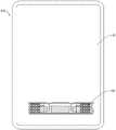
图8为本发明实施例提供的移动终端的结构示意图。FIG. 8 is a schematic structural diagram of a mobile terminal according to an embodiment of the present invention.
具体实施方式Detailed ways
下面将结合本发明实施例中的附图,对本发明实施例中的技术方案进行清楚、完整地描述,显然,所描述的实施例仅仅是本发明一部分实施例,而不是全部的实施例。基于本发明中的实施例,本领域普通技术人员在没有做出创造性劳动前提下所获得的所有其他实施例,都属于本发明保护的范围。The technical solutions in the embodiments of the present invention will be clearly and completely described below with reference to the accompanying drawings in the embodiments of the present invention. Obviously, the described embodiments are only a part of the embodiments of the present invention, but not all of the embodiments. Based on the embodiments of the present invention, all other embodiments obtained by those of ordinary skill in the art without creative efforts shall fall within the protection scope of the present invention.
请一并参阅图1、图2及图3,本发明实施例一提供的电声组件100包括电路板10和扬声器单体20。具体的,电路板10为印刷电路板(Printed Circuit Board,PCB),一种实施方式中,电路板10也可以为柔性电路板(Flexible Printed Circuit,FPC),电路板10上设有驱动电路,该驱动电路用于驱动扬声器单体20发声。一种实施方式中,当电声组件100应用于移动终端200中时,电路板10可以为移动终端200的主板。本实施例中,具体到图2,电路板10设有收容槽12,具体的,收容槽12为开设于电路板10表面的凹槽,一种实施方式中,收容槽12的深度与扬声器单体20的厚度相当,以使扬声器单体20可以收容于收容槽12中,当然,其他实施方式中,收容槽12的深度也可以小于扬声器单体20的厚度,以使扬声器单体20部分收容于收容槽12中。本实施例中,收容槽12包括底壁102和侧壁104,其中,底壁102为收容槽12槽底面,即收容槽12槽深最大的平面,侧壁104为连接底壁102与收容槽12开口的周面。Please refer to FIG. 1 , FIG. 2 and FIG. 3 together. The
具体到图2,扬声器单体20收容于收容槽12内,扬声器单体20包括内框架22和振膜24,振膜24的周缘固定连接于内框架22上,内框架22与振膜24之间形成发声腔1000,发声腔1000用于发声。一种实施方式中,内框架22固定于底壁102上。具体的,内框架22通过焊接等方式固定于底壁102上,内框架22具有一定的强度,内框架22可以是塑胶件,也可以是金属件。内框架22在底壁102的垂直投影环绕形成一个封闭的图形,也可以理解为,内框架22环绕形成中空的筒体,筒体的一端固定连接电路板10(底壁102),另一端固定连接振膜24,换言之,筒体(内框架22)的两端开口分别被电路板10和振膜24封上,从而在筒体中空的内部形成发声腔1000。本实施例中,扬声器单体20还包括驱动件,驱动件收容于发声腔1000内,电路板10上的驱动电路可以控制驱动件运动,从而致使振膜24振动,即发出声音,振膜24振动引起振膜24周围的空气振动,从而使声音向外传播。进一步的,根据电路板10的驱动电路改变振膜24振动的频率、振幅等因素,使扬声器单体20发出不同的声音。2 , the
结合图1和图3,电声组件100还包括盖板32,盖板32盖合于收容槽12的开口处,收容槽12的内壁包括底壁102与侧壁104,盖板32在底壁102的垂直投影位于侧壁104与内框架22之间,盖板32、内框架22、底壁102及侧壁104之间形成后音腔2000,内框架22设有泄漏孔40连通发声腔1000与后音腔2000。具体到图3,内框架22与侧壁104之间存在间隙,盖板32盖合在收容槽12的开口处,并将内框架22与侧壁104之间的间隙遮挡,换言之,盖板32、内框架22、底壁102、侧壁104依次相连,从而围绕形成后音腔2000。一种实施方式中,盖板32为环形,以与侧壁104和内框架22之间的环形间隙对应。本实施例中,振膜24抵顶于盖板32的内环,侧壁104至内框架22的距离大于底壁102至盖板32的距离,从而使后音腔2000形成于扬声器单体20的侧边,减小电声组件100的厚度尺寸,利于移动终端200的轻薄化设计。1 and 3, the
请参阅图1,本实施例中,扬声器单体20用于振动发出声波,从而形成声音,扬声器单体20的振动引起发声腔1000内的空气或气体的振动,扬声器单体20置于收容槽12中,扬声器单体20与侧壁104之间形成后音腔2000,后音腔2000内填充吸声颗粒74,泄漏孔40使得后音腔2000与扬声器单体20内部的发声腔1000连通,筛网50设于后音腔2000内,以阻止吸声颗粒74进入泄漏孔40,筛网50在扬声器单体20上的垂直投影覆盖泄漏孔40,筛网50的尺寸大于泄漏孔40的尺寸。泄漏孔40连通发声腔1000与后音腔2000,扬声器单体20工作时,发声腔1000内的气体被振动而压缩或拉伸;压缩气体时,气体通过泄漏孔40从发声腔1000进入后音腔2000,并引起后音腔2000内的吸声颗粒74振动,吸声颗粒74之间的摩擦消耗声波的能量,改变气体的振动效果,改变声波的特性;拉伸气体时,气体通过泄漏孔40从后音腔2000进入发声腔1000,并影响振膜24向外传播的声波的特性,从而优化电声组件100发出的声音的音质效果。Referring to FIG. 1 , in this embodiment, the
扬声器单体20收容于电路板10的收容槽12内,减小了扬声器单体20与电路板10的整体厚度尺寸,电路板10一方面设有驱动电路用于驱动扬声器单体20发生,一方面自身作为形成后音腔2000结构的一部分,电路板10省去了围成后音腔2000的底板等结构,减小了电声组件100的整体厚度,且不影响电声组件100发声的效果,有利于产品的轻薄化设计,优化用户体验。The
请参阅图1,本实施例中,内框架22包括背离底壁102的第一表面221,第一表面221与盖板32的顶面齐平。具体的,第一表面221为内框架22在扬声器单体20的厚度方向上的顶面。扬声器单体20全部收容于收容槽12中,扬声器单体20的厚度与电路板10的厚度融合,由于电路板10的厚度小于电路板10与扬声器的厚度之和,大大降低了电声组件100的厚度尺寸。Referring to FIG. 1 , in this embodiment, the
请参阅图1和图2,驱动件包括第一驱动件262与第二驱动件264,第一驱动件262固定于底壁102或内框架22上,第二驱动件264固定于振膜24,第二驱动件264用于相对第一驱动件262振动,以带动振膜24振动发声。具体的,第一驱动件262与第二驱动将在电路板10上的驱动电路的驱动下相对运动,第一驱动件262通过焊接或紧固件连接等方式固定于底壁102或内框架22上,第二驱动件264通过焊接或紧固件连接等方式固定连接振膜24,第一驱动件262相对第二驱动件264运动时,振膜24相对电路板10及内框架22振动,即振膜24发声。电路板10与内框架22固定连接,电路板10自身形成扬声器单体20的一部分,不仅用于电性驱动,还节省了扬声器单体20的结构整体厚度。Please refer to FIG. 1 and FIG. 2 , the driving member includes a
请参阅图2,本实施例中,第一驱动件262为磁体,第二驱动件264为线圈,第一驱动件262包括第一磁体262a与第二磁体262b,第一磁体262a固定于内框架22上,第二磁体262b固定于底壁102上,第二驱动件264位于第一磁体262a与第二磁体262b之间,第二驱动件264电连接至电路板10,电路板10设有驱动电路用于驱动第二驱动件264振动。具体的,第一磁体262a和第二磁体262b为永磁体,第一磁体262a与第二磁体262b之间形成稳定的、磁场方向不变的磁场,线圈位于第一磁体262a与第二磁体262b之间形成的磁场中,当电路板10的驱动电路向线圈输出变化的电流信号时,线圈内变化的电流使线圈在磁场中收到力的作用,从而使线圈带动振膜24一同振动。本实施例中,第一磁体262a固定于内框架22上,第二磁体262b位于第一磁体262a的内侧,第一磁体262a和第二磁体262b之间存在间距,以放置线圈。一种实施方式中,第一磁体262a和第二磁体262b也可以为电磁体,即第一磁体262a和第二磁体262b的磁力大小根据流经第一磁体262a和第二磁体262b的电流大小二变化,从而通过改变第一磁体262a与第二磁体262b的磁场方向及大小使线圈或振膜24相对第一驱动件262振动。Referring to FIG. 2, in this embodiment, the first driving
请参阅图1和图2,一种实施方式中,振膜24在周缘和几何中心之间设有褶皱72。褶皱72沿振膜24的周向延伸。褶皱72减小振膜24的张力,从而使得振膜24在靠近几何中心的区域更容易产生形变振动。褶皱72固定连接第二驱动件264,方便第二驱动件264带动振膜24产生形变。振膜24的材质可以是纸质、纤维材质、金属材质、羊毛材质、蚕丝材质等。Referring to FIGS. 1 and 2 , in one embodiment, the
请参阅图1和图3,本实施例中,第一磁体262a在内框架22上的垂直投影与泄漏孔40错开。一种实施方式中,泄漏孔40可以是圆孔,也可以是方形孔等。泄漏孔40开设于内框架22上,换言之,连通泄漏孔40前后的空间不占用电声组件100厚度尺寸,且仍然能够使发声腔1000与后音腔2000连通,第一磁体262a固定在内框架22上且与泄漏孔40错开,不遮挡气体的流动路径,有利于产品的轻薄化设计,提高用户体验。Referring to FIGS. 1 and 3 , in this embodiment, the vertical projection of the
请参阅图1,本实施例中,电声组件100还包括吸声颗粒74,吸声颗粒74填充于后音腔2000内。电声组件100还包括筛网50,筛网50设于后音腔2000内,筛网50固定于内框架22上,且筛网50覆盖泄漏孔40。一种实施方式中,筛网50为纱布。内框架22包括面对后音腔2000的外壁面220,纱布可以是遮盖泄漏孔40在外壁面220的开口。通过筛网50遮盖泄漏孔40,避免吸声颗粒74进入发声腔1000,避免影响扬声器单体20发声。筛网50遮盖泄漏孔40,使得吸声颗粒74可以完全填充于后音腔2000内,而不需要先对吸声颗粒74进行封装后再放置于后音腔2000内,既提升了电声组件100的音质,又减少了电声组件100的生产成本。Referring to FIG. 1 , in this embodiment, the electro-
请参阅图4,一种实施方式中,泄漏孔40内设有支承杆400,筛网50贴合支承杆400,支承杆400用于加固筛网50与外壁面220的连接。具体的,支承杆400辅助撑平筛网50,支承杆400与吸声颗粒74分别位于筛网50的相对的两侧,吸声颗粒74由于自身重力或产品摇晃产生对筛网50的挤压力,若挤压力过大会导致筛网50从外壁面220脱落,支承杆400从筛网50背离吸声颗粒74的一侧向筛网50提供支撑力,避免筛网50形变而脱落,降低了产品的维护周期,降低了产品的维护成本。一种实施方式中,支承杆400的数量为两个,且交叉设置。Referring to FIG. 4 , in one embodiment, the
扬声器单体20收容于电路板10的收容槽12内,减小了扬声器单体20与电路板10的整体厚度尺寸,电路板10一方面设有驱动电路用于驱动扬声器单体20发生,一方面自身作为形成后音腔2000结构的一部分,电路板10省去了围成后音腔2000的底板等结构,减小了电声组件100的整体厚度,且不影响电声组件100发声的效果,有利于产品的轻薄化设计,优化用户体验。The
请一并参阅图5、图6及图7,本发明实施例二提供的电声组件100与实施例一的区别在于,泄漏孔40包括第一泄漏孔42与第二泄漏孔44,第一泄漏孔42位于第一磁体262a在内框架22的垂直投影与振膜24之间,第二泄漏孔44位于第一磁体262a在内框架22的垂直投影与底壁102之间。两个泄漏孔40可以增大发声腔1000与后音腔2000之间的气体交换速率,从而提升音质效果,进一步的,第一泄漏孔42与第二泄漏孔44的配合使用可以从发声腔1000的不同位置连通发声腔1000与后音腔2000,相较于仅从一个位置连通发声腔1000与后音腔2000,更有利于发声腔1000与后音腔2000的气体交换。Please refer to FIG. 5 , FIG. 6 and FIG. 7 together. The difference between the
具体到图7,第一磁体262a包括面对振膜24的第一侧壁2622,第一泄漏孔42的内壁与第一侧壁2622平齐,从而最大化第一泄漏孔42的尺寸,第一泄漏孔42位于振膜24与第一磁体262a在内框架22的垂直投影之间,在不影响内框架22的强度的前提下,增大第一泄漏孔42的尺寸有利于增大单位时间气体进出后音腔2000与发声腔1000的量,即气体进出后音腔2000与发声腔1000的速率,从而加强后音腔2000对电声组件100的音质提升效果。7, the
请继续参阅图7,本实施例中,第一磁体262a还包括面对底壁102的第二侧壁2624,第二泄漏孔44的内壁与第二侧壁2624平齐,从而最大化第二泄漏孔44的尺寸,第二泄漏孔44位于第一磁体262a与底壁102之间,在不影响内框架22的强度的前提下,增大第二泄漏孔44的尺寸有利于增大单位时间气体进出后音腔2000与发声腔1000的量,即气体进出后音腔2000与发声腔1000的速率,从而加强后音腔2000对电声组件100的音质提升效果。Please continue to refer to FIG. 7. In this embodiment, the
进一步的,第二泄漏孔44的内壁与底壁102平齐,从而最大化第二泄漏孔44的尺寸,第二泄漏孔44位于第一驱动件262与底壁102之间,在不影响内框架22的强度的前提下,增大第二泄漏孔44的尺寸有利于增大单位时间气体进出后音腔2000与发声腔1000的量,即气体进出后音腔2000与发声腔1000的速率,从而加强后音腔2000对电声组件100的音质提升效果。Further, the inner wall of the
扬声器单体20收容于电路板10的收容槽12内,减小了扬声器单体20与电路板10的整体厚度尺寸,电路板10一方面设有驱动电路用于驱动扬声器单体20发生,一方面自身作为形成后音腔2000结构的一部分,电路板10省去了围成后音腔2000的底板等结构,减小了电声组件100的整体厚度,且不影响电声组件100发声的效果,有利于产品的轻薄化设计,优化用户体验。The
请参阅图8,本发明实施例还提供一种移动终端200,包括本发明实施例提供的电声组件100。具体的,移动终端200还包括壳体92,电声组件100固定于壳体92的底端。可以理解的是,移动终端200可以是手机、平板电脑、笔记本电脑等。Referring to FIG. 8 , an embodiment of the present invention further provides a
扬声器单体20收容于电路板10的收容槽12内,减小了扬声器单体20与电路板10的整体厚度尺寸,电路板10一方面设有驱动电路用于驱动扬声器单体20发生,一方面自身作为形成后音腔2000结构的一部分,电路板10省去了围成后音腔2000的底板等结构,减小了电声组件100的整体厚度,且不影响电声组件100发声的效果,有利于产品的轻薄化设计,优化用户体验。The
以上所揭露的仅为本发明几种较佳实施例而已,当然不能以此来限定本发明之权利范围,本领域普通技术人员可以理解实现上述实施例的全部或部分流程,并依本发明权利要求所作的等同变化,仍属于发明所涵盖的范围。The above disclosures are only a few preferred embodiments of the present invention, which of course cannot limit the scope of the rights of the present invention. Those of ordinary skill in the art can understand that all or part of the procedures for implementing the above-mentioned embodiments can be realized according to the rights of the present invention. The equivalent changes required to be made still belong to the scope covered by the invention.
Claims (8)
Translated fromChinesePriority Applications (1)
| Application Number | Priority Date | Filing Date | Title |
|---|---|---|---|
| CN201711240638.2ACN107809707B (en) | 2017-11-30 | 2017-11-30 | Electroacoustic component and mobile terminal |
Applications Claiming Priority (1)
| Application Number | Priority Date | Filing Date | Title |
|---|---|---|---|
| CN201711240638.2ACN107809707B (en) | 2017-11-30 | 2017-11-30 | Electroacoustic component and mobile terminal |
Publications (2)
| Publication Number | Publication Date |
|---|---|
| CN107809707A CN107809707A (en) | 2018-03-16 |
| CN107809707Btrue CN107809707B (en) | 2020-03-03 |
Family
ID=61590871
Family Applications (1)
| Application Number | Title | Priority Date | Filing Date |
|---|---|---|---|
| CN201711240638.2AActiveCN107809707B (en) | 2017-11-30 | 2017-11-30 | Electroacoustic component and mobile terminal |
Country Status (1)
| Country | Link |
|---|---|
| CN (1) | CN107809707B (en) |
Families Citing this family (4)
| Publication number | Priority date | Publication date | Assignee | Title |
|---|---|---|---|---|
| CN110958507B (en) | 2019-11-22 | 2021-05-28 | 歌尔股份有限公司 | Speaker module and electronic equipment |
| CN112788166B (en)* | 2021-01-06 | 2022-12-27 | Oppo广东移动通信有限公司 | Electronic device |
| CN115515059B (en)* | 2021-06-22 | 2025-03-21 | 海能达通信股份有限公司 | Speaker modules and electronic devices |
| CN113992774B (en)* | 2021-11-18 | 2024-04-02 | Oppo广东移动通信有限公司 | Mobile Terminal |
Citations (5)
| Publication number | Priority date | Publication date | Assignee | Title |
|---|---|---|---|---|
| CN201966990U (en)* | 2010-12-13 | 2011-09-07 | 瑞声光电科技(常州)有限公司 | Encapsulating structure for loudspeaker |
| CN203251422U (en)* | 2013-04-15 | 2013-10-23 | 瑞声科技(南京)有限公司 | Portable electroacoustic device |
| CN106412776A (en)* | 2016-11-04 | 2017-02-15 | 惠州Tcl移动通信有限公司 | Mobile terminal and loudspeaker assembly |
| CN106851504A (en)* | 2017-03-14 | 2017-06-13 | 广东欧珀移动通信有限公司 | Electroacoustic component, electroacoustic device and mobile terminal |
| CN206559633U (en)* | 2017-03-14 | 2017-10-13 | 广东欧珀移动通信有限公司 | Electroacoustic component, electroacoustic device and mobile terminal |
- 2017
- 2017-11-30CNCN201711240638.2Apatent/CN107809707B/enactiveActive
Patent Citations (5)
| Publication number | Priority date | Publication date | Assignee | Title |
|---|---|---|---|---|
| CN201966990U (en)* | 2010-12-13 | 2011-09-07 | 瑞声光电科技(常州)有限公司 | Encapsulating structure for loudspeaker |
| CN203251422U (en)* | 2013-04-15 | 2013-10-23 | 瑞声科技(南京)有限公司 | Portable electroacoustic device |
| CN106412776A (en)* | 2016-11-04 | 2017-02-15 | 惠州Tcl移动通信有限公司 | Mobile terminal and loudspeaker assembly |
| CN106851504A (en)* | 2017-03-14 | 2017-06-13 | 广东欧珀移动通信有限公司 | Electroacoustic component, electroacoustic device and mobile terminal |
| CN206559633U (en)* | 2017-03-14 | 2017-10-13 | 广东欧珀移动通信有限公司 | Electroacoustic component, electroacoustic device and mobile terminal |
Also Published As
| Publication number | Publication date |
|---|---|
| CN107809707A (en) | 2018-03-16 |
Similar Documents
| Publication | Publication Date | Title |
|---|---|---|
| CN108882089B (en) | Receiver and mobile terminal | |
| CN107809707B (en) | Electroacoustic component and mobile terminal | |
| TWI689209B (en) | Speaker, loudspeaking device and mobile terminal | |
| CN106851504A (en) | Electroacoustic component, electroacoustic device and mobile terminal | |
| CN107948891A (en) | Electroacoustic component, electroacoustic device and mobile terminal | |
| CN106303858A (en) | A kind of speaker and terminal unit | |
| CN205320275U (en) | Two -way miniature speaker | |
| WO2023160191A9 (en) | Loudspeaker module and electronic device | |
| CN107592598B (en) | Electroacoustic components, electroacoustic devices and mobile terminals | |
| CN101444109A (en) | Loudspeaker with reduced rocking tendency | |
| CN120282077A (en) | Sound producing device and electronic equipment | |
| CN205040024U (en) | Two -way miniature speaker | |
| CN111601221A (en) | High-pitch sound production device | |
| CN105657621B (en) | A kind of loudspeaker assembly and mobile terminal | |
| CN214381362U (en) | sound device | |
| CN111711897B (en) | A sound device module | |
| CN206559633U (en) | Electroacoustic component, electroacoustic device and mobile terminal | |
| TW201929559A (en) | Speaker and electronic device using same | |
| CN107809708B (en) | Electroacoustic components, electroacoustic devices and mobile terminals | |
| CN108012226A (en) | Electroacoustic component and mobile terminal | |
| CN214675665U (en) | Helmholtz brake chamber horn | |
| TW202316868A (en) | Speaker | |
| KR102167410B1 (en) | Hybrid actuator and multimedia apparatus having the same | |
| CN107454525A (en) | Electroacoustic component, electroacoustic device and mobile terminal | |
| CN107426656B (en) | Electroacoustic component, electroacoustic device and mobile terminal |
Legal Events
| Date | Code | Title | Description |
|---|---|---|---|
| PB01 | Publication | ||
| PB01 | Publication | ||
| SE01 | Entry into force of request for substantive examination | ||
| SE01 | Entry into force of request for substantive examination | ||
| CB02 | Change of applicant information | ||
| CB02 | Change of applicant information | Address after:Changan town in Guangdong province Dongguan 523860 usha Beach Road No. 18 Applicant after:GUANGDONG OPPO MOBILE TELECOMMUNICATIONS CORP., Ltd. Address before:523860 No. 18 Wusha Haibin Road, Chang'an Town, Dongguan City, Guangdong Province Applicant before:GUANGDONG OPPO MOBILE TELECOMMUNICATIONS CORP., Ltd. | |
| GR01 | Patent grant | ||
| GR01 | Patent grant |